Embed Size (px)
Citation preview

920786-03 Rev. - 09/15
IMPORTANT NOTICEUse TM Series meters with water and other chemicals compatible with wetted compo-nents. Do not use to meter fuel or incompat-ible chemicals. This TM Series meter features a computer for local electronic display plus a pulse output cable delivering raw pulses from the meter electronics to provide a digital signal to customer interfacing equipment. The computer display measures in gallons or litres. Refer to the Calibration Section for details.
These meters are not legal for trade applications.
TM Series meters are very sensitive to electric noise if operated within 1 to 2 inches of some electric motors or other sources of electronic noise.
TM Series Electronic Water MetersOwner's Manual
SAVE THESE INSTRUCTIONS
INSTALLATION
ConnectionsInstall your meter in-line either horizontally or vertically or at the end of the hose adjacent to the nozzle. Installation to metal connections is not recommended. Install as follows:
1. Plan to install turbine with a minimum straight pipe length as follows:
• Upstream from the turbine, allow a mini-mum straight pipe length of 10 times the internal diameter of the turbine.
• Downstream from the turbine, allow a minimum straight pipe length of 5 times the internal diameter of the turbine.
2. For Spigot (Pipe) End use only primer and solvents approved for PVC gluing.
For NPT Fittings wrap all connections with 3 to 4 wraps of thread tape (optional to use pipe thread sealant). Make sure the tape does not intrude into the flow path.
3. Attach meter with arrow pointed in the direc-tion of fluid flow.
4. For NPT Fittings - Hand tighten the meter at the housing ends. Do not use a wrench or similar tool to tighten. This can damage the housing.
TM Meter with Computer Display & Pulse Output

2 920786-03 Rev. -
Compatibility of this product’s material and the process fluid and/or environment should be considered prior to putting into service.
WARNING
Product should never be operated outside its published specifications for temperature or pressure. See specifications for your model.
WARNING
Make sure flow and pressure have been eliminated from process pipe prior to installing or removing product.
WARNING
Always use appropriate thread sealant when connecting product to process piping.
WARNING
To protect against leakage, seal all pipe threads with an appropriate sealing com-pound. Make sure the sealing compound does not intrude into the flow path.
CAUTION
NOTE: If connecting to new male pipe threads, burrs and curls can adversely affect accuracy. Correct the problem prior to turbine installation.
Installation near high electromagnetic fields and high current fields is not recommended and may result in inaccurate readings.
CAUTION
Output PulseThe output pulse trough the cable is a raw pulse. For each rotation of the turbine rotor, a specific number of pulses are transmitted via the attached cable. Pulse amounts can vary depending on pipe/meter size, flowrate, fluid type, etc. See table below for reference information.
Meter Size Typ. Pulses per GallonTM050 2,400TM075 1,100TM100 570TM150 213TM200 100
A Calibration Report with specific calibration information for this TM Series meter is also included for your reference.
The pulse cable White wire is signal and the Black wire is common (GND).
NOTE: Some interface devices may not have an internal pull-up resistor. Use a minimum 820 ohms resistor if necessary (See Figure 1).
Figure 1
CUSTOMERINTERFACEEQUIPMENT
5-30 VDC
- PULSE
BLACK - COMMON GND
INPUT
V+PULL-UPRESISTOR
WHITE
FIG. 1
3920786-03 Rev. -
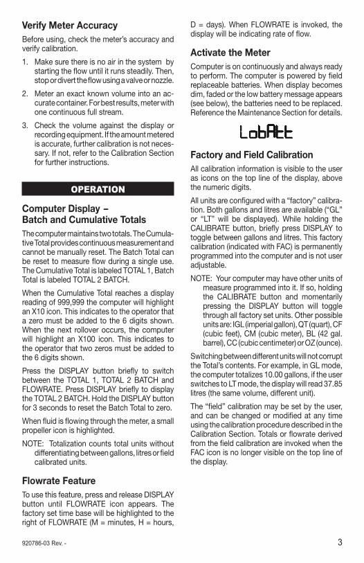
Verify Meter AccuracyBefore using, check the meter’s accuracy and verify calibration.
1. Make sure there is no air in the system by starting the flow until it runs steadily. Then, stop or divert the flow using a valve or nozzle.
2. Meter an exact known volume into an ac-curate container. For best results, meter with one continuous full stream.
3. Check the volume against the display or recording equipment. If the amount metered is accurate, further calibration is not neces-sary. If not, refer to the Calibration Section for further instructions.
OPERATION
Computer Display – Batch and Cumulative TotalsThe computer maintains two totals. The Cumula-tive Total provides continuous measurement and cannot be manually reset. The Batch Total can be reset to measure flow during a single use. The Cumulative Total is labeled TOTAL 1, Batch Total is labeled TOTAL 2 BATCH.
When the Cumulative Total reaches a display reading of 999,999 the computer will highlight an X10 icon. This indicates to the operator that a zero must be added to the 6 digits shown. When the next rollover occurs, the computer will highlight an X100 icon. This indicates to the operator that two zeros must be added to the 6 digits shown.
Press the DISPLAY button briefly to switch between the TOTAL 1, TOTAL 2 BATCH and FLOWRATE. Press DISPLAY briefly to display the TOTAL 2 BATCH. Hold the DISPLAY button for 3 seconds to reset the Batch Total to zero.
When fluid is flowing through the meter, a small propeller icon is highlighted.
NOTE: Totalization counts total units without differentiating between gallons, litres or field calibrated units.
Flowrate FeatureTo use this feature, press and release DISPLAY button until FLOWRATE icon appears. The factory set time base will be highlighted to the right of FLOWRATE (M = minutes, H = hours,
D = days). When FLOWRATE is invoked, the display will be indicating rate of flow.
Activate the MeterComputer is on continuously and always ready to perform. The computer is powered by field replaceable batteries. When display becomes dim, faded or the low battery message appears (see below), the batteries need to be replaced. Reference the Maintenance Section for details.
Factory and Field CalibrationAll calibration information is visible to the user as icons on the top line of the display, above the numeric digits.
All units are configured with a “factory” calibra-tion. Both gallons and litres are available (“GL” or “LT” will be displayed). While holding the CALIBRATE button, briefly press DISPLAY to toggle between gallons and litres. This factory calibration (indicated with FAC) is permanently programmed into the computer and is not user adjustable.
NOTE: Your computer may have other units of measure programmed into it. If so, holding the CALIBRATE button and momentarily pressing the DISPLAY button will toggle through all factory set units. Other possible units are: IGL (imperial gallon), QT (quart), CF (cubic feet), CM (cubic meter), BL (42 gal. barrel), CC (cubic centimeter) or OZ (ounce).
Switching between different units will not corrupt the Total’s contents. For example, in GL mode, the computer totalizes 10.00 gallons, if the user switches to LT mode, the display will read 37.85 litres (the same volume, different unit).
The “field” calibration may be set by the user, and can be changed or modified at any time using the calibration procedure described in the Calibration Section. Totals or flowrate derived from the field calibration are invoked when the FAC icon is no longer visible on the top line of the display.

4 920786-03 Rev. -
CALIBRATION
Verify Accuracy Before Beginning Field CalibrationFor the most accurate results, dispense at a flowrate which best simulates your actual oper-ating conditions. Avoid “dribbling” more fluid or repeatedly starting and stopping the flow. This can result in less accurate calibrations.
Make sure you meet the meter’s minimum flowrate requirements:
TM Series Meters
½ inch meter 1 GPM (3.8 LPM) ¾ inch meter 2 GPM (7.5 LPM) 1 inch meter 5 GPM (18.8 LPM) 1 ½ inch meter 10 GPM (37.5 LPM) 2 inch meter 20 GPM (75 LPM)
The use of a uniformly dependable, accurate calibration container is recommended for the most accurate results. Due to high flowrate, it is strongly recommended that calibration be completed with a combination of volume and weight using fine resolution scales.
For best results, the meter should be installed and purged of air before field calibration.
Field Calibration with Computer DisplayField Calibration and Factory Calibration are defined in the Operation Section. Factory calibration settings are programmed into each computer during manufacturing, using water at 70° F (21° C). Readings using the Factory Calibration (FAC) may not be accurate in some situations, for example, under extreme tem-perature conditions, non-standard plumbing configurations or with fluids other than water.
Field Calibration Procedures (Correction Factor Method)1. To calibrate, press and hold the CALIBRATE
and DISPLAY buttons for about 3 seconds until you see FLdCAL. Release both buttons and you will see CF - 00.0. You are now in the field calibration mode and values from -99.9% to +99.9% can be entered.
2. The +/– position appears either as an “under-score” character for plus, or as a “hyphen” character for minus. The DISPLAY button selects the position and the CALIBRATE
button toggles this character.
3. The DISPLAY button can then be pushed to select the numeric positions. Press the CALIBRATE button to scroll from 0 to 9. Enter the percentage of change you want the display to correct. When satisfied with the value, press both CALIBRATE and DIS-PLAY buttons simultaneously. CALEnd will be displayed and unit will go back to normal operation, less the FAC (factory calibration) icon.
4. All enabled units-of-measure remain visible and selectable – the entered correction will be applied to all enabled units.
5. To return to factory calibration (FAC), press and hold both CALIBRATE and DISPLAY buttons for about 3 seconds until FAcCAL is displayed. Then release buttons. Unit should return to normal operation and FAC icon is visible.
MAINTENANCEProper handling and care will extend the life and service of the meter.
Turbine RotorThe meter is virtually maintenance-free. How-ever, it is important the rotor moves freely. Keep the meter clean and free of contaminants.
If the rotor does not turn freely, apply a pene-trating lubricant on the rotor, shaft and bearings. Remove any debris or deposits from the rotor using a soft brush or small probe. Be careful not to damage the turbine rotor or supports.
Blowing compressed air through the tur-bine assembly could damage the rotor.
CAUTION
CAUTIONDo not allow liquids to dry inside the turbine.
CAUTIONHandle the rotor carefully. Small scratches or nicks can affect accuracy.
5920786-03 Rev. -
Battery ReplacementThe computer display is powered by two 3-volt lithium batteries which may be replaced while the meter is installed. When batteries are removed or lose power, the batch and cumula tive totals and the field and factory calibrations are re tained.
(Battery) – Avoid mechanical or electrical abuse. Batteries may explode or cause burns, if disassembled, crushed or exposed to fire or temperatures in excess of 212°F (100°C). Do not short circuit or install with incorrect polarity. DO NOT INCINERATE.
WARNING
Batteries should ONLY be replaced with P/N 113520-1 Kit (Includes two each P/N 902004-2 Batteries). Do not mix old with new. Do not use other brands or technologies.
CAUTION
Open battery cells should be disposed of in accordance with local regulations. Lithium batteries are best disposed of as a non-hazardous waste when fully or mostly discharged. EPA does not list or exempt Lithium as a hazardous waste. If waste lithium batteries are still fully charged or only partially discharged, they can be considered a reactive hazardous waste because of unconsumed lithium remaining in the battery. Such batteries may qualify as “Universal Waste” in many jurisdictions within the U.S. and thus can be shipped for disposal or recycling in accordance with Universal Waste requirements.
If the display becomes dim, blank or the low battery message appears (see below), replace the batteries as follows:
1. Remove the four Phillips-head screws from the face of the meter and lift the faceplate from the turbine.
2. Remove the old batteries and clean any corrosion from the terminals.
3. Install new batteries. Make sure the positive post is in the correct position.
4. When the batteries are replaced, the face-plate will power ON. Check the display to ensure normal functions have resumed before assembling again.
5. Reseat batteries, if necessary, and posi-tion the faceplate on the turbine housing. To avoid moisture damage, make sure the seal is fully seated. Tighten the four screws on the faceplate.

6 920786-03 Rev. -
SPECIFICATIONS
Inlet and Outlet:Spigot (Pipe) End Models:TM050-LP ½ inch Schd. 80, Spigot (Pipe)TM075-LP ¾ inch Schd. 80, Spigot (Pipe)TM100-LP 1 inch Schd. 80, Spigot (Pipe)TM150-LP 1 ½ inch Schd. 80, Spigot (Pipe)TM200-LP 2 inch Schd. 80, Spigot (Pipe)NPT Models:TM050-N-LP ½ inch NPTTM075-N-LP ¾ inch NPTTM100-N-LP 1 inch NPTTM150-N-LP 1 ½ inch NPTTM200-N-LP 2 inch NPT
Design Type: Turbine
Wetted Components:Housing: PVCJournal Bearings: CeramicShaft: Tungsten CarbideRotor and Supports: PVDFRetaining Washer: Stainless Steel
Max. Working Pressure: 225 PSIG @ 73° F
U.S. MeasurementUnit of Measure: Gallon
Flow Range:½ inch 1 - 10 GPM¾ inch 2 - 20 GPM1 inch 5 - 50 GPM1 ½ inch 10 - 100 GPM2 inch 20 - 200 GPM
Accuracy with Computer: ± 3.0% of read-ing (Accuracy can be improved with field calibration)
Operating Temperature: +32° to +140° F (Do not allow fluid to freeze inside meter.)
Storage Temperature: –40° to +158° F
Product Weight: Spigot (Pipe) NPT ½ in. .38 lbs. .55 lbs.
¾ in. .43 lbs. .67 lbs. 1 in. .49 lbs. .84 lbs. 1 ½ in. .66 lbs. 1.38 lbs. 2 in. .78 lbs. 1.78 lbs.
Dimensions - Inches (W x H x L):** Without Fitting With NPT Fitting ½" 2.1 x 2.5 x 4.3 2.1 x 2.7 x 6.0 ¾" 2.1 x 2.7 x 4.4 2.1 x 2.9 x 6.1 1" 2.1 x 2.9 x 4.5 2.1 x 3.1 x 6.5 1 ½" 2.1 x 3.6 x 5.4 2.3 x 3.8 x 7.6 2" 2.4 x 4.1 x 5.5 3.5 x 4.4 x 7.9
Cable Length: 5 FT.
7920786-03 Rev. -
PARTSThe following replacement parts and acces-sories are available for the TM Series meters:
Part No. Description113520-1 Battery Replacement Kit116000-1 Calibration Container, Large (5 gallon)125508-03 ½ inch, Turbine Assy Kit125508-04 ½ inch NPT, PVC Turbine Assy Kit125510-03 ¾ inch, Turbine Assy Kit125510-04 ¾ inch NPT, PVC Turbine Assy Kit125512-03 1 inch, Turbine Assy Kit125512-04 1 inch NPT, PVC Turbine Assy Kit125514-03 1 ½ inch, Turbine Assy Kit125514-04 1 ½ inch NPT, PVC Turbine Assy Kit125516-03 2 inch, Turbine Assy Kit125516-04 2 inch NPT, PVC Turbine Assy Kit901002-52 Seal
Computer Kits:125509-04 ½ inch, Computer Assy Kit w/Pulse125511-04 ¾ inch, Computer Assy Kit w/Pulse125513-04 1 inch, Computer Assy Kit w/Pulse125515-04 1 ½ inch, Computer Assy Kit w/Pulse125517-04 2 inch, Computer Assy Kit w/Pulse
SERVICEFor warranty consideration, contact your local
distributor. If you need further assistance, contact the GPI Customer Service Department at:
1-888-996-3837
You will need to:
• Provide information from the decal on your meter.
• Receive a Return Authorization number.
• Flush any fluid from the meter before shipping to the factory.
If possible leave customer installed fittings or ample length of bare pipe for reinstallation.
CAUTIONDo not return the meter without specific authority from the GPI Customer Service Department. Due to strict regulations governing transportation, handling, and disposal of hazardous or flammable liquids, GPI will not accept meters for rework unless they are completely free of liquid residue.
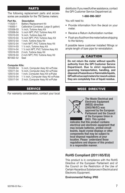
WEEE DIRECTIVE
RoHS Compliant (2011/65/EU)This product is in compliance with the RoHS Directive of the European Parliament and of the Council on the Restriction of the Use of Certain Hazardous Substances in Electrical and Electronic Equipment.
Environmental Rating: IP65
8 920786-03 Rev. -
Declaration of ConformityManufacturer's Name: Great Plains Industries, Inc.Manufacturer's Address: 5252 East 36th Street North
Wichita, KS USA 67220-3205
Declares, that the product: Product Name: TM Series Water Meter Model Numbers: TM050-LP TM150-LP TM50-N-LP TM150-N-LP TM075-LP TM200-LP TM075-N-LP TM200-N-LP TM100-LP TM100-N-LP
Conforms to the following Standards: EMC: EN 61000-6-2 (2005) EN 61000-6-3 (2007)
Supplementary Information:
- "The products comply with the requirements of the EMC Directive 2004/108/EC and RoHS 2 Directive 2011/65/EU". This product has insufficient internal volume size or pressure ratings to meet a pressure directive.
- This product is not recommended for custody transfer or application where levying by consumption takes place.
I the undersigned, hereby declare that the equipment specified above conforms to the above Directive(s) and Standard(s).
Signature: Full Name: Victor Lukic Position: President Great Plains Industries, Inc. Place: Wichita, KS USA May 2015

9920786-03 Rev. -

10 920786-03 Rev. -

11920786-03 Rev. -

09/15 920786-03 Rev. -
Limited Warranty PolicyGreat Plains Industries, Inc. 5252 E. 36th Street North, Wichita, KS USA 67220-3205, hereby provides a limited warranty against defects in material and workmanship on all products manufactured by Great Plains Industries, Inc. This product includes a 2 year warranty from date of purchase as evidenced by the original sales receipt. A 30 month warranty from product date of manufacture will apply in cases where the original sales receipt is not available. Reference product labeling for the warranty expiration date based on 30 months from date of manufacture. Manufacturer’s sole obligation under the foregoing warranties will be limited to either, at Manufacturer’s option, replacing or repairing defective Goods (subject to limitations hereinafter provided) or refunding the purchase price for such Goods theretofore paid by the Buyer, and Buyer’s exclusive remedy for breach of any such warranties will be enforcement of such obligations of Manufacturer. The warranty shall extend to the purchaser of this product and to any person to whom such product is transferred during the warranty period.
This warranty shall not apply if:
A. the product has been altered or modified outside the warrantor’s duly appointed representative;
B. the product has been subjected to neglect, misuse, abuse or damage or has been installed or operated other than in accordance with the manufacturer’s operating instructions.
To make a claim against this warranty, contact the GPI Customer Service Department at 316-686-7361 or 800-835-0113. Or by mail at:
Great Plains Industries, Inc.5252 E. 36th St. North
Wichita, KS, USA 67220-3205
GPI will step you through a product troubleshooting process to determine appropriate corrective actions.
GREAT PLAINS INDUSTRIES, INC., EXCLUDES LIABILITY UNDER THIS WARRANTY FOR DIRECT, INDIRECT, INCIDENTAL AND CONSEQUENTIAL DAMAGES INCURRED IN THE USE OR LOSS OF USE OF THE PRODUCT WARRANTED HEREUNDER.
The company herewith expressly disclaims any warranty of merchantability or fitness for any particular purpose other than for which it was designed.
This warranty gives you specific rights and you may also have other rights which vary from U.S. state to U.S. state.
Note: In compliance with MAGNUSON MOSS CONSUMER WARRANTY ACT – Part 702 (governs the resale availability of the warranty terms).
© 2015 GREAT PLAINS INDUSTRIES, INC. All Rights Reserved. and FLOMEC are registered trademarks of Great Plains Industries, Inc.