Embed Size (px)
Citation preview
0
-/--- - u- $I OAK RIDGE N ~ I O ~ ' LABO~~TORY -:# -- operated by
UNION CARBIDE CORPORATION NUCLEAR DIVISION
for the U.S. A T O M I C ENERGY C O M M I S S I O N
ORNL- TM- L167
COPY NO. - 28 DATE - %rch 10, 1967
J. A. Russell, Jr. D. J. Knowles
&ci l i ty radiation and contamination alarm systems were irkstalled i n the Chemical Technology Alpha LEbbomtory, Building 3508, t o continuously and auto- mtztically monitor neutron mdiatfon (by three neutron rate-burst detectors) and a i r contaIination (%y Pi= constant alpha afr. monitors) i n the entire fac i l - i ty . These instruments and other components in the nehork provide health plrysics monitoring information, sound local s l a m when abnormal eanditims occur, and indicate the abmrm&l conditions on a central panel board.
Operating personnel are f i r s t given warning when a "high level" is detected by a cov~stant alpha air mcaaitor. The neutron detectars operate "rate" 0s "buret" alarms when the alarm levels are exceeded.
6 'Q The building evacuation systiem operatea automatically when Cwo or more
constant alpha air monitors detect a "high level" of air conb~~~ ina t ion ox when &o or more neu-kron monitoss detect a neutron burst o r a l'hhigh-xate" level.
I(O'TlEE This document- contains information of a prelimrnary nature and was prepared primarily far internal use at the Oek Ridge Norlonol Loborofory. It is subject to revision or correction and therefore does net represent a final report.
DISCLAIMER
This report was prepared as an account of work sponsored by an agency of the United States Government. Neither the United States Government nor any agency Thereof, nor any of their employees, makes any warranty, express or implied, or assumes any legal liability or responsibility for the accuracy, completeness, or usefulness of any information, apparatus, product, or process disclosed, or represents that its use would not infringe privately owned rights. Reference herein to any specific commercial product, process, or service by trade name, trademark, manufacturer, or otherwise does not necessarily constitute or imply its endorsement, recommendation, or favoring by the United States Government or any agency thereof. The views and opinions of authors expressed herein do not necessarily state or reflect those of the United States Government or any agency thereof.

DISCLAIMER
Portions of this document may be illegible in electronic image products. Images are produced from the best available original document.
This nport wor prmpmmed as on account of G B v e r n m .garcod wmk. Naither th, Unitad States,
nsr tha Comrlssi&, nor m y pmrson ectlng on khdf of the ~ i s s i a n i
A. k k W atvy m s d y or r~g~vamMdium, axprecsud or impiimd, with r a w to th. occumcy,
ccnrpiotanrrs, n vwfulni.ss of h i n f i m ~ i a a c&ai.md i n this mpart, er thm the use of m y infeanotian, opparotus, mathod, or p t w s s d i m l ~ l k d +n this wort moy mot i d t l y r r
privately awnad rigktsj a
b Assunus m y l iahi l i t i rs wtth rmspacf te the ur. of, a far dawoges rmrulting from the u u ot:
m y iafarmajlan, oppwufur, method, ar procmso d l ru laud in this roparf.
As used i n the above, "psrson odih on b k l f of thm bnrmissiont* inc ldas any employee 01
ecnrraetrit ot the Gmmtission, or mmpley- 04 such ronttactot, to thm m a w fkat such emplopmo
or contrustor of t k CMmnissiow, or empleyoe of d rantroctor pmpmrs, dlsamminutas, or
prcvidas ocw$s la, m y L ~ f w m ~ i a w pwmmt to hi* r m p l o m n t or c-ot uitt~ thb Clvmmlsrten,
a hi8 rmgleyrmnt wleh such cawecte.

THIS PAGE
WAS INTENTIONALLY
LEFTBLANK
Page < .
. . . . . . . . . . . . . . . . . . . . . . . . . . . . . 1.' Abstract L
. . . . . . . . . . . . . . . . . . . . . . . . . . . . . 2. Introduction 4
3. Description . . . . . . . . . . . . . . . . . . . . . . . . . . 4 . . . . . . . . . . . . . . . . . . . . . . . . . . . 3.1 System 4
. . . . . . . . . . . . . . . . . . . . . 3.2.1 Panel Board '(
. . . I . . . . . . . . . . . 3.2.2 Constant Alpha A i r Monitors 7
. 3.2.3 Neutron Rate and Burst Detector . . . . ' . . . . . . ' . 10
. . . . . . . . . . . . . . . . . . . 3.2.4 IndicatorModule 11
. . . . . . . . . . . . . . . . . 3.2.5 Coincidence Module 12 .
. . . . . . . . . . . . . . . . . . . . . 3i2.6 Buzzer Module 1 3
. . . . . . . . . . . . . . 3.2.7 Evacuation Alarm &vices 1 3
. . . . . . . . . . . . . . . . . . . . . 3.2.8 Power Supplies 14
. . . . . . . . . . . . . . . . . . . . . . . 3.3 Drawings . ' 16
4. Checkout and Operating Procedures f o r Fac i l i t y Radiation and . . . . . . . . . . . . . . . . . . . contamination ~ larm system 16
nlrr.P.ISED FOR AKNOUNC-4
IA RUCLEbF. SSCIPBCE 4EJTUZTS
I
T M s report was Prepared a s an account of Government sponsored work. ~ ~ ~ t h ~ ~ the united , States, nor the Commission, nor nny person acting on behalf of the comrnlsslon: I
A. M*es any warranty or representation, expressed o r Implled. ~ t h respect to the t mcY, com~letenesa. or usefulness of the InformnUon con,,,[ned in t h t ~ rPprt. or mat the use
of UY Inrnrmarlon, appnmtue, mcthd . u r process dlsclosed in this report may not tnsringe / privately owned r l ~ h t s : o r
8. Assumes liabflltles Wth respect to the uae of, or for damages r e s u l t l n ~ f r ~ g ) I IIRP of nny Infvnmotlon, nPwratua. ~rrrrllud. or proceas dlsclosed in thls report.
As used In the above. "person acUng on behalf of the Commlsslon" Includes any em- ployee o r contractor of the Commlsslon, o r employee of such contractor, to the extent UIst
I such employee or cont racbr of the Commlsslon, o r employee of such contractor prepares, , dlssernlnates, or provldes access to. any Informntlon pursuant to Me employment o r contract , wlth the Comrnlsslon, or hls employment wlth such contractor.
i
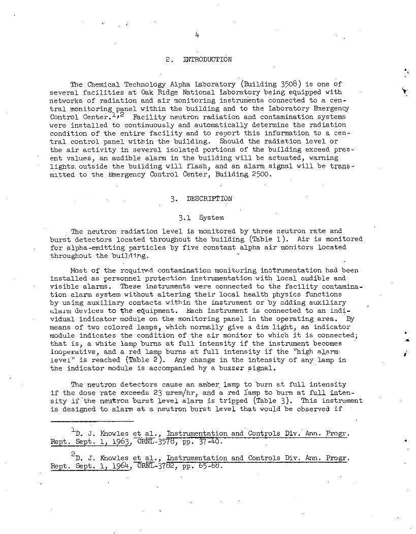
The Chemical Technology Alpha Laboratory (Building 3508) i s one of severa l f a c i l i t i e s a t Oak Ridge National Laboratory being equipped with networks of rad ia t ion and a i r monitoring instruments connected t o a cen- t r a l monitoring panel wi thin the bui lding and t o the Laboratory Emergency Control c en t e i . l r 2 F a c i l i t y neutron rad ia t ion and contamination systems were i n s t a l l e d t o continuously and automatically determine t h e rad ia t ion condit ion of t h e e n t i r e f a c i l i t y and t o repor t t h i s information t o a cen- t r a l con t ro l panel wi thin t he bui lding. Should the rad ia t ion l e v e l o r t h e a i r a c t i v i t y i n severa l i so la ted port ions of the bui lding exceed pres- en t values, an audible alarm i n the bu i ld ing w i l l be actuated, warning l i g h t s , outs ide t h e bu i ld ing w i l l f l a sh , and an alarm s igna l w i l l be trans- mltted t o t he hhergency Cbntrol Center, Building 2500.
3.1 System
The neutron rad ia t ion l e v e l i s monitored by th ree neutron r a t e and (
b u r s t dktectors located throughout t he bui lding a able 1 ) . A i r i s monitored . f o r alpha-emitt ing p a r t i c l e s by f i v e constant alpha a i r monitors located
throughout the buiJ,din g . %
Most of the rcqu.ired, contamination 111oni'l;oring instrumentation had been i n s t a l l e d a s personnel protect ion ins tnmenta t ion with l o c a l audible and v i s i b l e alarms. These instruments were connected t o t he f a c i l i t y contamina- t i o n alarm system without a l t e r i n g t h e i r l o c a l hea l th physics functions by using aux i l i a ry contacts within t he instrument o r by adding aux i l i a ry ala~.m dev-lces t o the equipment. kbch instrument i s connected t o an ind i - v idual ind ica tor module on t h e monitoring panel i n the operating area . By means of two colored lamps, which normally give a dim l i g h t , an ind ica tor module ind ica tes the condit ion of the a i r monitor t o which it i s connected; t h a t i s , a white lamp burns a t f u l l i n t ens i t y i f t h e instrument becomes inopera-Live, and a red lamp burns a t f u l l i n t ens i t y i f t h e "high alarm. leve l" i s reached (Table 2 ) . Any change i n the i n t ens i t y of any lamp i n t h e ind ica tor module i s accompanied by 8, buzzer s igna l .
The neutron de tec tors cause an amber lamp t o b u m a,% full. i n t ens i t y if the dose ra te exceeds 23 mrem/hr, and a red Tamp t o burn a t f u l l in ten- s i t y it' 'the neutron b u r s t l e v e l alarm i s t r ipped a able 3) . This instrument i s designed t o alarm a t a neutron b u r s t l e v e l t h a t would be observed i f
ID. J. Knowles e t ,-...-,. a 1 -.-., J ~ n s t r u m e r k a t i ~ n a n d Controls Div . Ann. Pmgr . Rept. Sept. 1, 1963, ORNL-3578, pp. 37-40.
2 ~ . J. Knowles e t - a1 -* Instrumentation and Controls Div. Ann. Pmgr. Rept. Sept. 1, 1964, Om-3782, pp. 65-68.
a c r i t i c a l i t y occurred a t a d is tance of 200 f t . For these instruments the re i s no indicat ion when an instrument becomes inoperative. Any change
/ . in the i n t ens i t y of any lamp, t h a t i s , from dim t o b r i , gh t , i s announced by a -buzzer module.
The high-level alarm outputs of t he ind ica tor module f o r t he constant alpha a i r monitors a r e connected so t h a t the evacuation alarms operate when any two constant alpha a i r monitors a r e i n the "high l eve l " alarm condit ion. The alarm outputs of the neutron bu r s t - r a t e detectors a r e connected so t h a t evacuation alarms sound whenever two o r more instruments a r e i n e i t h e r a bu r s t o r high-rate alarm condition. No inoperative alarm s igna l i s a v a i l - able on the neutron monitor.
I
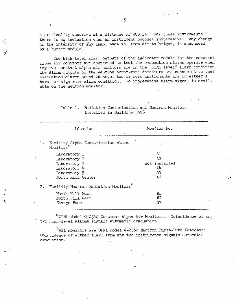
Table' 1. Radiation Contamination and Neutron Monitors Ins ta l l ed i n Building 3508
, . Locat ion Monitor No.
1. Fac i l i t y Alpha Contamination Alarm ~ o n i t o r s "
Laboratory 1 Laboratory 2 Laboratory 3 Laboratory 4 Iaboratory 5 North H a l l Center
2. F a c i l i t y Neutron Radiation Monitors b
North H a l l East North Ha11 W e ~ t Change Room
A 1 A 2
not i n s t a l l e d A4 . A5 ~6
"ORNL Model Q-2340 Constant Alpha A i r Monitors. Coincidence of any two high-level alarms s ignals automatic evacuation.
b ~ l l monitors a r e ORNL model Q-2562 Neutron Burst-Rate Detectors. Coincidence of e i t h e r alarm from any two instruments s igna l s automatic evacuation,
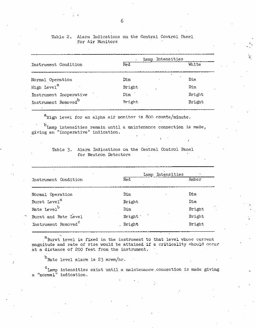
Table 2. Alarm l i ~ d i c a t i o i ~ s on. t he Ceiitral Control Panel f o r A i r Monitors
Tamp In t ens i t i e s Instrument Condition Red White
Normal Operation D i m D i m
High Levela Bright , D im
Instrument Inoperative . D i m Bright b Instrument Removed Bright, Bright
a High l e v e l f o r an alpha a i r monitor is 800 counts/minute. a
'Lamp i n t e n s i t i e s remain u n t i l a maintenance Connection i s made, giving an "inoperative indicat ion.
I ' I
Table 3. Alarm Indications on t he Central Control Panel f o r Neutron Detectors
Instrument Condition Iamp In t ens i t i e s - . ...
Red Amber
N o m l Operation D i m D i m
Burst Levela
Rate Levelb
Bright
D i m
D i m
Bright
Burst and Rate .&vel Bright ' ' Bright C l5strument Removed . - Bright Bright
' \ a
. Burst l e v e l i s f ixed i n the instrument t o t h a t Level whose cr.ur~-en'l; magnitude and r a t e of r i s e would be a t t a ined i f a c r i t i c a l i t y should, occur a t a dis tance of 200 f ee t ' f r om. the instrument. .
b ~ t e l e v e l alarm i s 23 mremlhr.
.C Iamp I n t e n s i t i e s e x i s t u n t i l a riain-bermice ,connection i s made giving a "normal " indicat ion.
I
3.2 Components
3 .2 .1 Panel Board
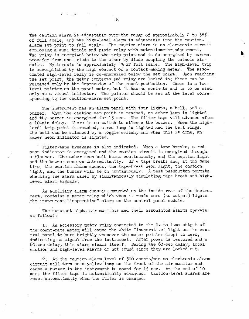
The cen t r a l panel board (Fig. 1 ) i n the o f f i c e a rea contains t he following equipment: two 12-module racks, one cen t r a l control chassis , and t he dc supply f o r the f a c i l i t y neutron rad ia t ion and contamination alarm system. Three modules used t o monitor the condition of t h e off-gas system a r e located i n the lower rack. An abnormal vacuum condition i s indicated by a buzzer and a b r igh t l i g h t on one of these modules. Since these u n i t s a r e not a pa r t of the contamination and neutron alarm system, they operate ne i ther the evacuation alarms nor the alarm s igna l t o t he Emergency Control Center. The f a c i l i t y rad ia t ion and contamination alarm iilodule racks contain one ind ica t ing mod.i.13.e f o r each instrument, coin- cidence -modules f o r each instrument group, a buzzer module, and a manual evacuation module.
The racks and modules a r e made of anodized aluminum. The modules have anodized Metalphoto f ron t panels. A Metalphoto t e x t s t r i p i s pro- vided a t the top of each rack f o r instrument i den t i f i c a t i on . The cen t r a l control chass is contains manual switches, t imers, rela;y s , and ~noiiitoring equipment which a r e pa r t s of t he system but not located i n modules.
3.2.2 Constant Alpha A i r Monitors
The alpha a i r monitors i n s t a l l e d i n the bui lding a r e ORNL model Q-2340 instruments (Fig. 2 ) .
This instrument consis ts of an a sp i r a t i ng system, a paper-tape f i l t e r , a s c i n t i l l a t i o n detector , a l i n e a r count-rate meter, a recorder, and v i s - i b l e and audible alarms. A i r i s drawn through the f i l t e r a t 3 cfm (con- t r o l l e d manually) by a Roots blower. A sample of dust i n the a i r i s col lected on t he paper-tape f i l t e r . The sample tape i s automatically advanced once every 24 hours and a f t e r a caution l e v e l alarm. The tape may be advanced manually a t any time by the operator. The detector , which counts t he sample a s it i s being col lected, i s a s i lve r -ac t iva ted zinc su l f i de s c i n t i l l a t o r having an e f f ec t i ve detector diameter of 1-718 i n . The detector window (nominal thickness of 1 mg/cm2) i s l i g h t - t i g h t .
The count-rate meter i s a l i n e a r duty-cycle t p e , u t i l i z i n g a s ing le range and having a high-voltage supply a s an i n t eg ra l p a r t . The normal range i s 0 t o 1000 counts/min, by t ranges of 0 t o 250, 0 t o 2500, 0 t o 5000, and 0 t o 10,000 counts/min a t f u l l sca le may be obtained by re luca l - ing two jumper wires under t h e chass is . The input voltage s e n s i t i v i t y of t he r a t c meter i s 200 mv. The ove ra l l accuracy oY the rate meter, irlclud- ing the e f f e c t of long-term d r i f t , is within 5%. The corona-regulated high-voltage supply i s nominally 900 v with 2150-v adjustment. The maximum - load curren? i s 20 va.
The r a t e meter has adjustable high-level and caution alarms and puts out a 1-ma fu l l - s ca l e s igna l t o dr ive an i n t eg ra l l y mounted Rustrak recorder.
The caut ion alarm ri.s a.d jus table over t h e rangc of approxiuwtely 2 t o 58% of f u l l scale , and t h e high-level alarm i s adjus table from t h e caution- alarm s e t point t o f u l l s ca l e . The caution alarm i s an e lec t ron ic c i r c u i t employing a dual t r i o d e and p l a t e re lay with potentiometer adjustment. The r e l a y i s energized below the t r i p point and i s de-energized by current b t r a n s f e r from one t r i o d e t o t he o ther by diode coupling the cathode c i r - c u i t s . Hysteresis i s approximately 4% of f u l l sca le . The high-level t r i p i s accomplished by t h e high contact on a contact-making meter. The asso'- c i a t ed high- level r e l a y is de-energized below t h e s e t point . Upon reaching t h e s e t point , t h e meter contacts and r e l ay a r e locked i n ; - t h e s e can be re leased only by t he depression of t he r e s e t pushbutton. There i s a low- l e v e l po in te r on t he panel meter, bu t it has no contacts and i s t o be used only a s a v i sua l ind ica tor . The po in te r should be s e t a t the l e v e l corre- sponding to, t he caution-alarm s e t point .
The instrument has an alarm pane1,with four l i g h t s , a b e l l , and a buzzer. When t h e caution s e t point i s reached,, an amber lamp i s li.ghtmed aiid t he buzzer i s energized f o r 1 5 sec. Thc f i l t e r tape w i l l advance a f t e r a 10-min delay. There i s no switch t o s i l ence t he buzzer. When the high- l e v e l t r i p point i s reached, a red lamp i s l igh ted and the b e l l r ings . The b e l l can be s i lenced by a toggle switch, and when t h i s is done, an amber neon ind ica tor i s l igh ted .
F i l t e r - t ape breakage i s a l so indicated. When a tape breaks, a red I neon ind ica tor is energized and t he caution c i r c u i t i s energi-zed, through
a f l a s h e r . The amber neon bulb bums continuously, and the ca-ution l i g h t and t he buzzer come. on in te rmi t ten t ly . If FI. tape breaks and, a t the same time, t h e caution alarm sounds, t he ta.pe-hr~a.k nmn light, tho caution l i g h t , and t he buzzer w i l l be on c ~ n t ~ i n u o u s l y . A t e s t pushbutton permits checking t he alarm panel by simultaneously simulating tape break and high- l e v e l a l a ~ ~ l i s igna l s .
An aux t l i a ry alarm chass is , mounted on t he ins ide r e a r of t h e i n s t ru - ment, contains a meter r e l a y which when it reads zero (no output) l i g h t s . the instrument "inoperative" alarm on t h e cen t r a l panei module.
The constant alpha a i r mon.it#ors and t h e i r associated alarms opemte as Pullows:
1. An accessory meter r e l ay connected t o t he 0- t o l-ma output of t h e count-rate meteq w i l l cause t he white "inoperative" l i g h t on t he cen- t r a l panel t o burn b r i g h t l y whenever t h e meter po in te r drops t o zero, i nd i ca t i ng no c igna l t'rom t h e instruuier~'t. After power i s res tored and a 60-sec delay, t h i s alarm c l ea r s i t s e l f . During the 60-sec delay, l o c a l caut ion and high-level alarms do not sound s ince they a r e locked ou t .
2 . ' A-t -lie caution alarm l e v e l of 500 counts/min an e lec t ron ic alarm c i r c u i t w i l l t u rn on a yellow'lamp on t h e f ron t of the a i r monitor and cause a buzzer i n t h e instrument t o sound f o r 15 sec. A t the end of 10 min, t he f i l t e r tape i s automatically advanced. Caution-level alarms a r e r e s e t automatically when t he f i l t e r i s changed.
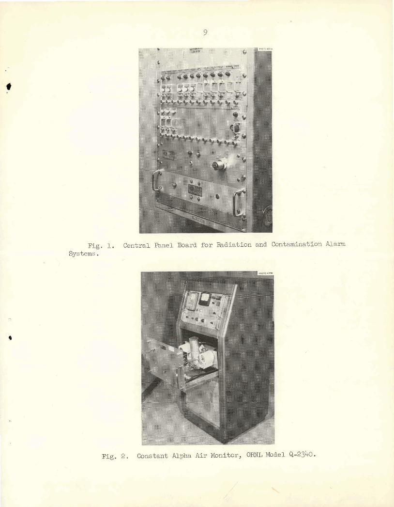
Fig. 1. Central Panel Board f o r Radiation and Contamination Alamn Systems .
Fig. 2. Constant Alpha A i r Monitor, 6RNL Model &-2340.
3. A t the high alarm level (800 comts/min) the panel metcr relay on the instrument causes the red lamp on the instrument and the red "Hi k v e l " lamp on the central panel t o burn brightly. The be l l on the con- s tant alpha a i r monitor sounds. These alarms are reset by advancing the f i l t e r tape and by pressing the manual reset button on the monitor.
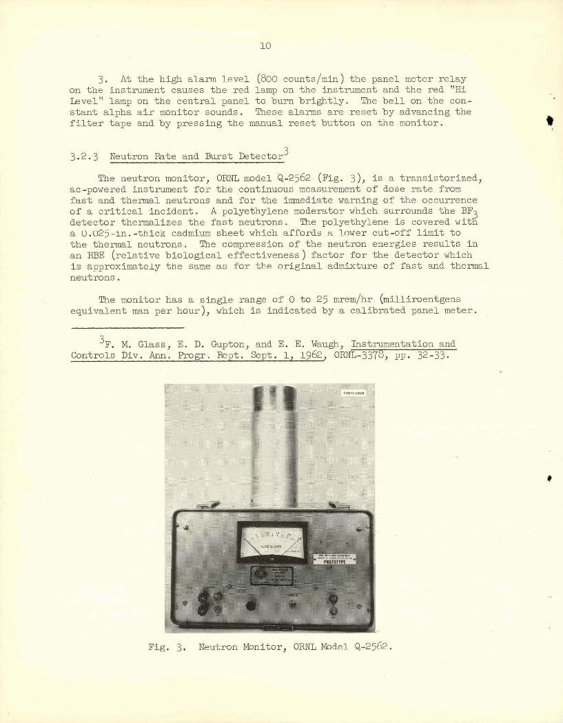
3.2.3 Neutron Rate and Burst Detector 3
The neutron monitor, ORNL model Q-2562 (Fig. 3), i s a transistorized, ac-powered instrument fo r the continuous measurement of dose ra te from fa s t and thermal neutrons and for the immediate warning of the occurrence of a c r i t i c a l incident. A polyethylene moderator which surrounds the BF
a U.U25-in.-thick cadmium sheet which affords a Lower cut-off l i m i t t o I! detector thermalizes the f a s t neutrons. The polyethylene i s covered, w i t
the t h e m 1 neutrons. The compression of the neutron energies results i n an RBE (relative biological effectiveness) factor for the detector which i s approxfmately the same as for the original admixture of f a s t and thermal neutrons.
The monitor has a single range of 0 to 25 mrem/hr (milliroentgens equivalent man per hour), which is indicated by a calibrated panel meter.
3 ~ . M. Glass, E. D. Gupton, and E. E. Waugh, Instrumentation and Controls Div. Ann. BOP. ~ e p t . S p t . 1, 1962, ORNL-3378, PP* 32-33
& - . Neutron Monitor, ORNL Model Q-2562.
bm
A high-level alarm with manual rese t can be adjusted t o alarm a t any value within 0-24 mrem/hr. The output from the monitor can be fed t o a s t r i p chart recorder t o record the dose ra te . Aburs t alarm operates independently of the dose-rate circui t ry, which would be paralyzed by a f a s t excursion i n neutron l eve l before it could indicate an alarm condition. The response of the burs t detector is suf f ic ien t ly f a s t t o provide an alarm output when neutron bursts of only 20-psec duration originate from c r i t i c a l i nc i - dents up t o 200 f t from the detector. There i s no indication of burst alarin a t the instrument.
When the burst alarm i s tripped, a red lamp bums br ight ly on the indicator module a t the central alarm panel; when the dose-rate alarm l eve l i s exceeded, an amber lamp bums br ight ly on the indicator module a t the central alarm panel.
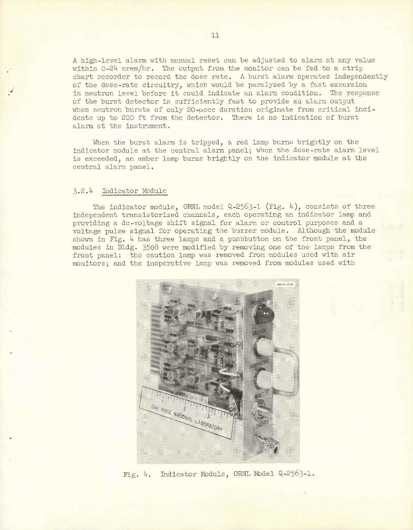
3.2.4 Indicator lbdule
The indicator module, ORNL model: Q-2563-1 ( ~ i ~ . 4), consists of three independent t ransis tor ized channels, each operating an indicator lamp and providing a dc-voltage s h i f t signal f o r alarm o r control purposes and a voltage pulse s ignal f o r operating the buzzer module. Although the module shown i n Fig. 4 has three lamps and a pushbutton on the f ront panel, the modules i n Bldg. 3588 were modified by removing one of the lamps from the f ront panel: the caution lamp was removed from modules used with a i r monitors; and the inoperative lamp was removed from modules used with
Fig. 4. Indicator Mdvlle, O W BSel &-2563-1.
*
neutron burst-rate detectors, and the face plate was replaced with vne bearing the legends '%urstl' qnd "dose." Each module i s 35.8 mm wide, 120 mm high, and 125.8 mm deep. All connections are made on printed s t r i p conhections a t the r ea r edge of the plug-in module.
When the instrument connected t o an indicator module i s operating normally, a l l lamps on that module are dim able 2) . When the module receives a s ignal t h a t the instrument i s operating abnormally o r tha t the high-level alarm values have been exceeded, the lamps bum at f u l l inten- s i ty : white for inoperative instrument, amber fo r a neutron "dose" level alarm, and red f o r neutron high ra t e o r "burst" alarm. Also, a signal generated by the module causes the buzzer t o sound. The white lamp indi- cation w i l l remain u n t i l the condition causing the alarm is cleared, a t which time the l a m p w i l l return t o the dim condition. The red and amber l i g h t s w i l l remain br ight u n t i l they are manually rese t by a pushbutton on the indicator module. If the indicator module is rese t when the alarm o r abnormal condition s t i l l exis ts , the lamps w i l l momentarily become dim when the rese t button i s depressed, and then w i l l become bright and the buzzer w i l l sound again when the rese t button i s released.
All model Q-2563 indicator modules have ident ical c i r cu i t s and can be interchanged o r replaced without a l te ra t ion . Some of the uni t s have been modified a s previously described by omitting parts o r changing panels. These un i t s a re designated by use of different suff ix numbers o r suf f ix l e t t e r s .
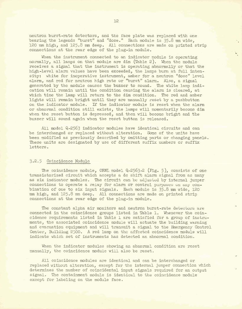
3.2.5 Coincidence Module
The coincidence module, ORNL model Q-2563-2 ( ~ i g . 5 ), consists of one t ransis tor ized c i r c u i t which accepts a dc s h i f t alarm signal from as many as six indicator modules. The c i r cu l t can be ttdjusled by internal jumper connections t o operate a re lay f o r alarm o r control pul-poses un arly C ~ I I I -
bination of one t o six input signals. &ch module is 35.8 mm wide, 120 mm high, and 125.8 mm deep. All connections are made on printed s t r i p connections a t the r ea r edge of the plug-in module.
The constant alpha a i r monitors and neutron burst-rate deLecLirrs aye connected i n the coincidence groups l i s t e d i n Table 1. Whenever the coin- cidence requirements l i s t e d i n Table 1 are sa t i s f i ed fo r a group of instru- ments, the associated coincidence module w i l l actuate the building waxnieg and evacuation equipment and w i l l transmit a s ignal t o the Ehergency Control CenLer, Bulldiug 2500. A red lamp on the affected coinoidenae module w i l l indicate which s e t of instruments has detected an abnormal condition'.
When the indicator modules showing an abnorrnal condition are rese t manually, the coincidence module w i l l a l so be reset .
All coincidence modules are ident ica l and can be interchanged o r replaced without a l te ra t ion , except for the internal jumper connection which determines the number of coincidental input signals required f o r an output signal. The containment module i s ident ical t o the coincidence module except f o r labeling on the module face.
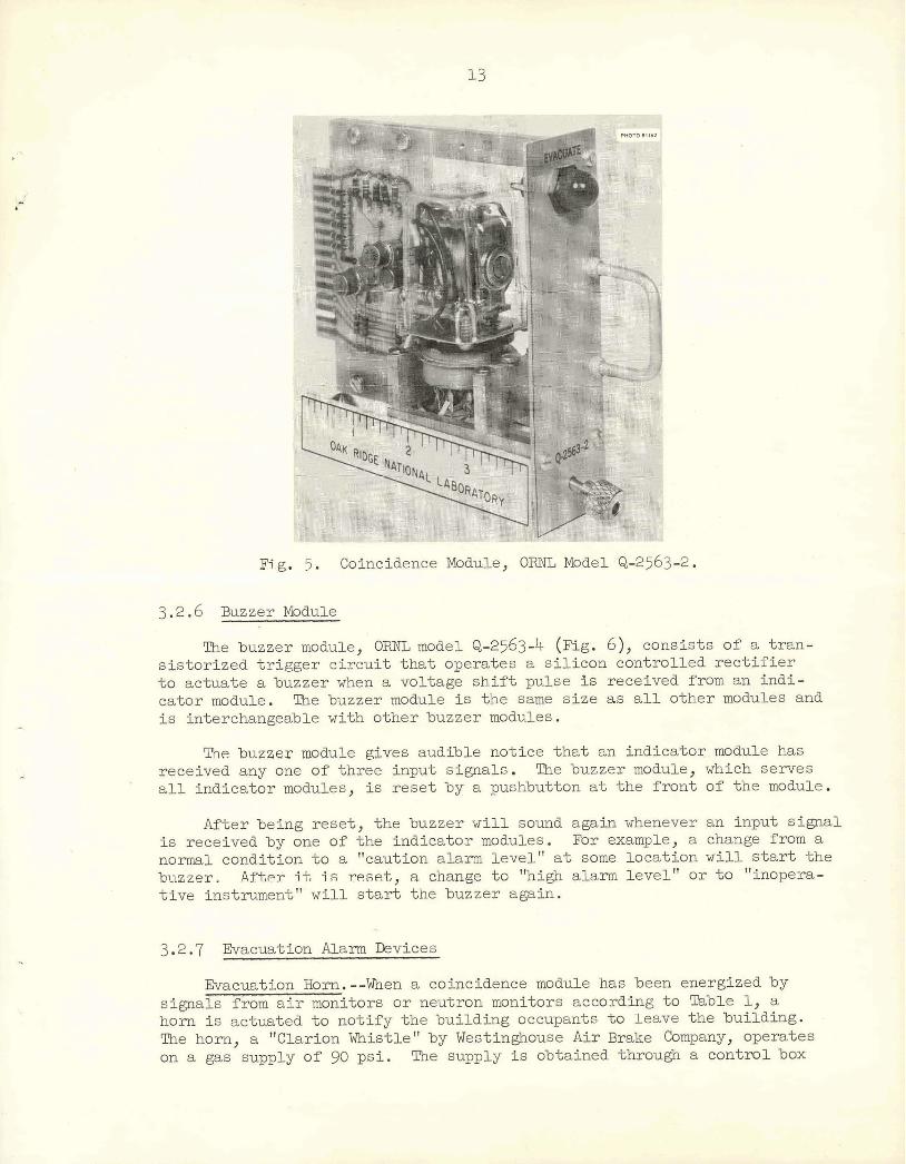
Buzzer Module
Tbe buzzes module, O m mo&eel Q-25.63-4 (EL@. $1, mwistFs d a t s n - ~Sstiorbzled tr9gger c i r e u i t %kt togam&@s 8 stlieom cm"%rcYLLed rediffrter .E;o acfjuate a b~;tzzex vhet?. a .uaL%age B~I% pulge 25 rect%"~~ed f W @ . ~ ~ W h - w t o r module. %e bu~zer m o u e is %be a ~ m size as all otbermo&3&1 and i s inhachang&~le w i t h ~Lhziei Wzze3 aodules ..
- I~ZZGX ~Q@U$Q &ves audible not$ ~ . e %bat indrtcaWx, m&1& W s xeceived any on$ of % W e @?'put sipals, ~ U Z L B ~ w&nle,, which Beme@
0 a l l %ndicatozr meduL&, i~ e,Se.fi by a pshbutbn at %he $&ant OF %be wdulie, *
After bebg rese*, %be lms~ex will sou- ~ga3.11 whenever ippu% ~iQgwB i s reca5ve.d by one of tPLE $n&icaLar m & a l @ B . &IF 8~a3mp2s, a ohang: fmB s n o m l cbm&it%on $0 a "o&~%&~rr, ~bkWia &ewI1' a% ~;@rne l w c & t 5 ~ > ~ 1 f % l l EJ&z% lfjbe b~~z 'asr a .&%er 3% -l Ft $a$nf, a cbmge "hi& a';Lflr@ ~ e & & " BF %o '"2~0pera- 'tlue inslmpxit" ' w t l l a m tibe bm~W a&Zn.
3.2.7 Evacuation Alarm Devices
Evacuation Horn.--When a coincidence module has been energized by * . signals f r o m a i r monitors o r neutron monitors according t o Table 1, a horn i s actuated t o not i fy the building occupants t o leave the building. The horn, a "Clarion Whistle" by Westinghouse A i r Brake Company, operates on a gas supply of 90 ps i . The supply i s obtained through a control box
which contains a pressure regulating valve, pressure switches which moni- t o r tank and regulated pressures, and a solenoid valve that i s opened by an e lec t r i ca l signal from the coincidence module. Two standard high pres- sure gas bott les f i l l e d with oil-pumped nitrogen to a pressure of approxi- mately 1800 ps i are connected t o a manifold through isolating valves t o the control box. Normally, the valves are s e t so tha t one tank i s supplying the system, and the second tank i s valved off as a standby supply. The valve arrangement pexmits replacement of an exhausted tank with a f i l l ed tank without disturbing the operational status of the horn alarm assembly. The horn i s operated by a voltage applied momentarily t o the solenoid '
valve i n the control box; the valve w i l l remain open un t i l it i s closed manually by pressing the mushroom head of the valve stem inward. The horn w i l l sound for about 4 min on one f i l l e d gas bott le .
The noxmal gas pressures for proper operation of the horn are not l ess than 1000 psig tank pressure and 80 t o 120 psig l ine pressure t o the solenoid valve. Abnormal pressures are indicated by a red lamp (labeled "horn trouble") on the central control panel board. lfne dim lamp indi- cates nomnal pressures, and a bright lamp indicates abnormal pressures. Inspectior of the gages w i l l indicate whether the tank pressure or the l ine pressure is abnormal.
Beacon Lights.--Four Federal Sign and Signal Corp., model 27S, 110-v beacons with magenta colored lens are installed on the corners of the building t o wa& personnel outside tha t the building has been evacuated. These beacons a re actuated by a signal from a.coincidence module, and they are automatically stopped when the coincidence module has returned t o a nuzmal conditf on.
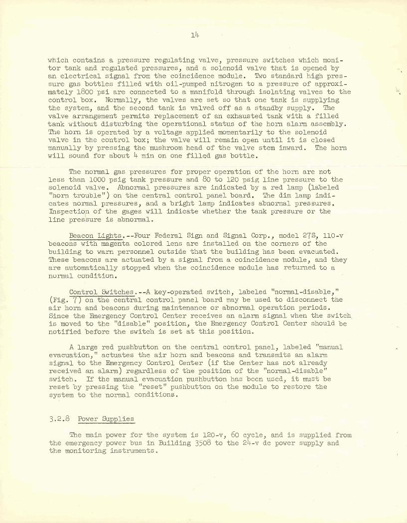
Control Switches. --A key-operated switch, labeled "noxmal-disable," (Fig. 7 ) on the central control panel board may be used t o disconnect the
" -
a i r horn and beacons during maintenance or abnormal operation periods. Since the Eknergency Control Center receives an alamn signal when the switch. is moved t o the "disable" position, the Emergency Control Center should be notified before the switch i s se t a t th i s position.
A large red pushbutton on the central control panel, labeled "manual evacuation," actuates the a i r horn and beacons and transmits an alarm signal t o the Eknergency Control Center ( i f the Center has not already received an alarm) regardless of the position of the "normal-disable" switch. If the manual evacuation pushbutton has been used, it mustbe reset by pressing the "reset" pushbutton on the module t o restore the system t o the noxmal conditions.
3.2.8 Power mpplies
The main power for the system is 120-v, 60 cycle, and i s supplied from the emergency power bus i n Building 3508 to the 24-v dc power supply and the monitoring instruments.
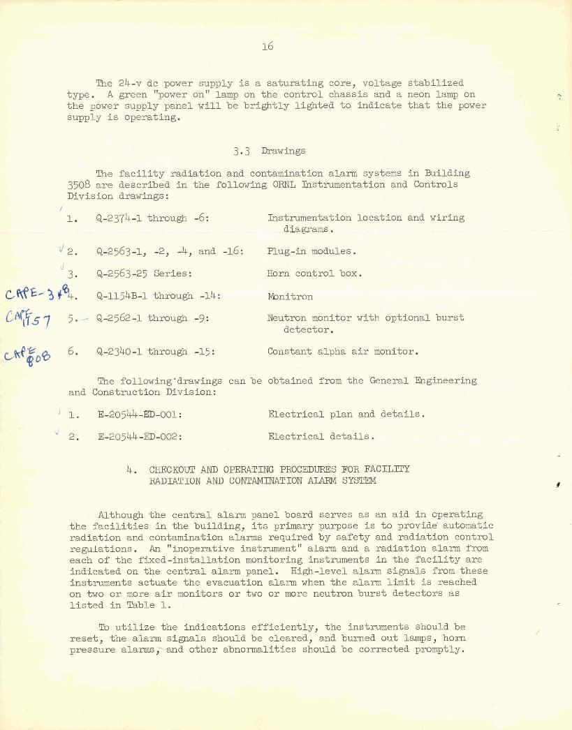
The 24-v dc power supply i s a saturat ing core, voltage s tabi l ized type. A green "power on" lamp on the control chassis and a neon lamp on the power supply panel w i l l be br ight ly l ighted t o indicate tha t the power supply i s operating.
3.3 Drawings
The f a c i l i t y radiat ion and contamination alarm systems i n Building 3508 a re described i n the following ORNL Wstrumentation and Controls Division drawings:
f 1. Q-2374-1 through -6: Instrumentat ion locat ion and wiring
diatgrms.
4 2. Q-2563-1, -2, -4, and -16: mug-in modules.
2 3. &-2563 -25 Series : Horn control box.
M E . Q-1154~-1 through -14 : Monitron
&go0 6. Q-2340-1 through -15:
Neutron monitor with optional burs t detector. -
.-7 Constant alpha a i r monitor.
The following'drawings can be obtained from the General Engineering and Construct ion Division :
Electr ical plan and de ta i l s .
Electr ical de ta i l s .
4. CHECKOUT AND OPERATING PROCEDURES FOR FACILITY RADIATION AND CONTAMINATION ALARM SYSTEM
Although the cent ra l alarm panel board serves as an aid i n operating the f a c i l i t i e s i n the building, i t s primary purpose i s t o providg automatic radiat ion and contamination alarms required by safety and radiation control regulations. A n "inoperative instrument1' alarm and a radiation alarm from each of the f ixed-instal la t ion monitoring instruments i n the f a c i l i t y a re indicated on the cent ra l alarm panel. High-level alarm signals from these instruments actuate the evacuation alarm when the alarm l i m i t is reached on two o r more a i r monitors ox two o r more neutron burs t detectors a s l i s t e d i n Table 1. .
To u t i l i z e the indications ef f ic ient ly , the instruments should be rese t , the alarm signals should be cleared, and burned out lamps, horn pressure alarms,"--and other abnormalities should be corrected promptly.
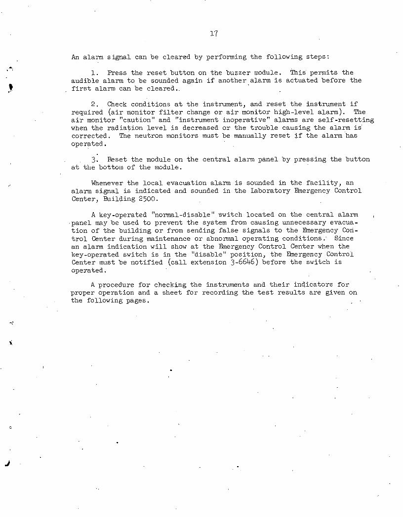
An alarm s igna l can be cleared by performing the following s teps:
1. Press t he r e se t button on the buzzer module. This permits the audible alarm t o be sounded again i f another alarm i s actuated before t he
- f i r s t alarm can be cleared ..
2. Check conditions a t t he instrument, and r e se t t he instrument i f required ( a i r monitor f i l t e r change o r a i r monitor high-level alarm). The a i r monitor "caution" and "instrument inoperative" alarms a r e s e l f - r e se t t i ng when the radia t ion l e v e l i s decreased o r t he t rouble causing t h e alarm is . corrected. The neutron monitors must be manually r e se t i f t he alarm'has operated.
3. Reset the module on t he cen t r a l alarm panel by press ing t he button at the bottom of the uiodule.
Whenever the l o c a l evacuation alarm i s sounded i n t he f a c i l i t y , an alarm s igna l i s indicated and sounded i n the Laboratory Emergency Control Center, Building 2500.
A key-operated "normal-disable" 'switch located on the cen t r a l alarm .panel may be used t o prevent the system from causing unnecessary evacua- t i o n of t he bui lding o r from sending f a l s e s igna l s t o t he Elnergency Con- t r o l Center during maintenance o r abnormal operating conditions .' Since an alarm indicat ion w i l l show a t the Emergency Control Center when the key-operated switch i s i n the "disable" posi t ion, the Emergency Control Center must be no t i f i ed ( c a l l extension 3-6646) before t h e switch i s operated.
A procedure f o r checking the instruments and t h e i r indicators f o r proper operation and a sheet f o r recording t he t e s t r e s u l t s a r e given on the following pages.
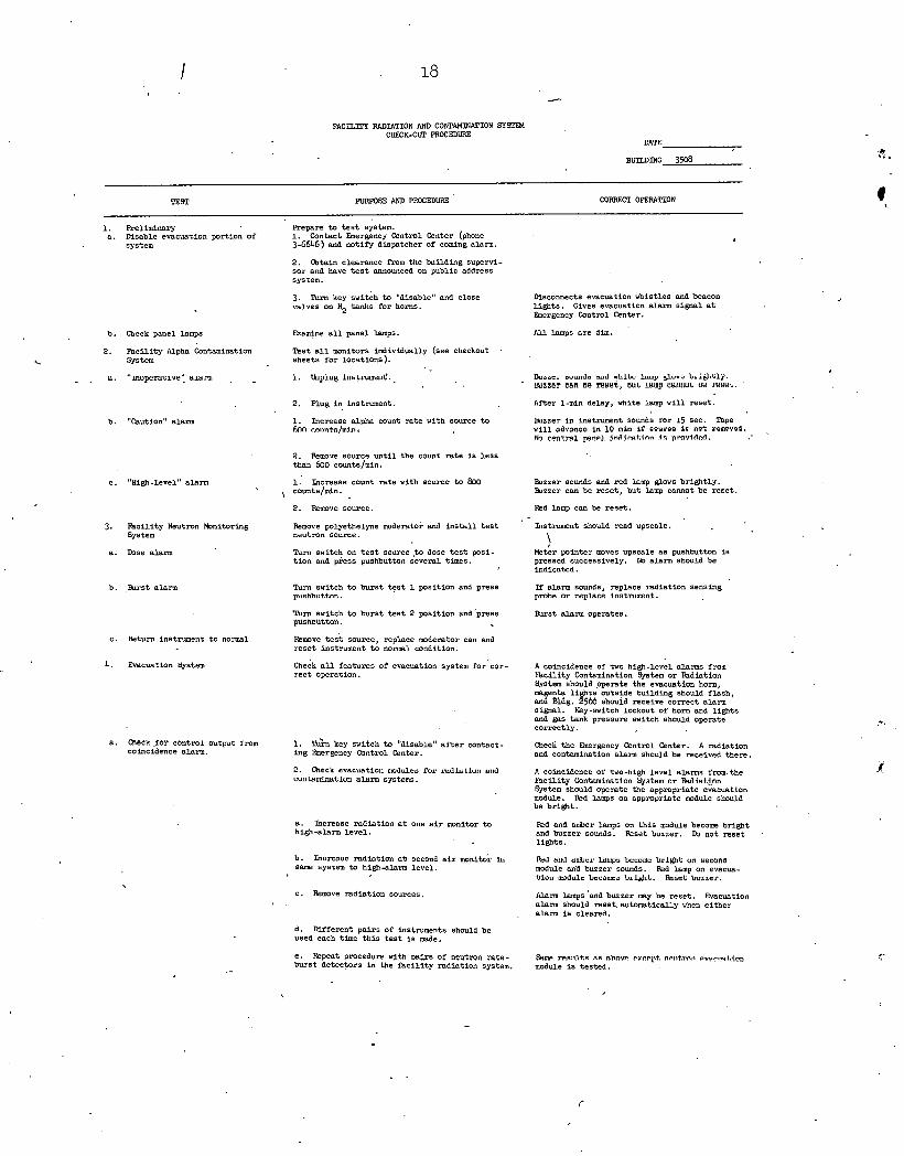
FACILlTl RADIATION AND C O ~ A T I O N SYSPPI CHWK-Om PROCEDURE
UAYE
BUILDING 3508
TEST PURFOSE AND mMCEDURE CORRFCI OPERPlTION
1. Reliminary Repare t o t e s t system. a . Msable evacuation portion of 1. Contact Emergency Control Center (phone
system 3-6646.) and not ify dispatcher of coming alarm.
2. Obtain clearance from the building supervi- sor and have t e s t announced on public address system.
3. %rn key switch t o "disable" and close D i s c o ~ e c t s evacuation nbist les and beacon valves on N2 tanks for horns. l ights . Gives evacuation alarm signal a t
Emergency Control Center.
b . Check panel lamps mamine a l l panel Lamps. A l l lamps a re dim.
2. Faci l i ty Alpha Contamination Test a l l m n i t o r s individually (see checkout System sheets fo r locations ).
DULL=, IUUII~. ( Y I ~ ILILI: lYu,p &mi) L~id.lilj. mzzer can ae wrter, UUL u u p cluuiu~ ue I W ~ L .
2. mug in i n s t m e n t . ~ f t e ~ delay, white lamp wi l l reset .
b . "Caution" alarm 1. Increase alpha count r a t e with source t o lhzzer in instrument sounds mr 15 6ec. mpe hnn r.n1bn6a/min wi l l advanoo in 10 min if couroo i c not romrvod.
W cont.t+rl p n ~ 1 . jnrlimtion i n pmvirled.
2. Remove source u n t i l the count r a t e i s l e s s than 600 counts/min.
c. "High-Level" alarm 1. Increase count rate with source t o 800 &zzer sounds and red lamp glows bright ly. ' , counts/uSn. k z z e r can be reset , but Lamp CaMOt be reset .
2. Remove source. Red lamp can be reset .
3. Faci l i ty Neutron tbnitoring System
a . m s e alarm
Remove polyethelyne d e r a t o r and i n s t a l l t e s t neutron source.
Instrument should read upscale.
Meter pointer mves upscale a s pushbutton i s pressed successively. M alarm should be indicated .
Tum switch on t e s t source.to dose t e s t posi- t i on and piess pushbutton several times.
If alarm sounds, replace ladlat ion sensing pmhn nr mplncn instnlmnnt.
b. . h s t alarm Tum switch t o burst t e s t 1 position and press p~mhhnttnn.
'nun switch pusnnuttan.
burst t e s t 2 position and press &st alarm operates.
c . Xeturn instrument t o normal Remve t e s t source, replace moderator can and rese t instrument t o normal condition.
4. Evacuation System heck a l l features of evacuation system for 'cor- r ec t operation.
A coincidence of two high-level alanns fmm l b c i l i t y Contaminntion System o r k d i a t i o n S.-tem should ppemte the evacuation horn, magenta li t s outside building should f lash, and Bldg. $66 sbouid receive correct alarm signal. Key-switch lockout of horn and l ights and gas tank pressure switch should operate correctly.
1. I& key switch t o "disable" a f t e r contact- ing Ebergency Control Center.
a . QLeCK .for conrml output from coincidence alarm.
Check the Eaergency Control Center. A radiation and contamination a l a m should be received there.
C. Obeck evacuation uMlulrs for iwllallutl u0 CuuLhUILIuLlun nurm systems.
A coincidence Of two-high Level alarms from.the k8ci l i ty bntRmi.mtlnn System nr hrliat.$,nn System should operate the appropriate evacuation module. Red lamps on appropriate mdule should be bright .
a . Increase radiation a t one a i r monitor t o high-alarm leve l .
Red and amber lamps on t h i s module become bright and buzzer sounds. Reset buzzer. b not reset ,
l i gh t s .
h. Incrcnac mdint ion n.b 3econd a i r monitui. i t ,
same system t o high-alarm level . &d cud anbar lawpa b r m m brlght un second module ana buzzer sounds. Red lamp on evacua- lrloxr d u l s Lecirue~ L i l d ~ L . %set Luleer.
C. Remve radiation sources. Alarm lamps 'and buzzer my he reset . Evacuation alarm should reset automatically when e i the r alarm i s cleared.
d. Mfferent pa i r s of instruments should be used each time t h i s t e s t i s mde.
e. Repeat procedure wsth w i r s of neutmn ra te - burst detectors in the f a c i l i t y radiation system.
h n m s l l l t . ~ nfi ahnve except. n ~ r ~ t m n rvemet. i~h module I s tested.
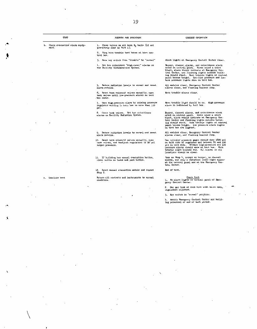
PURPOSE AND PRCCEDURE CORRECT OrnTION
b. check evacuation alarm equip- 1. Close valves on a l l horn N2 tanks ( i f not ment . previously done in Part 1) .
2. Plug born trouble t e s t boxes a t horn con- t r o l box.
3. M v e key switch from "disable" t o "normal" Alam l igh t s a t Rnergency Contml Center clear.
4. Set two coincident "high-level" alarms on the Faci l i ty Contamination System.
Buzzer, channel alarms, and coincidence a l a m noted on central panel. Horns sound a short b l a s t , alann should indicate a t Rnergency Con- tml Center, and flashing l igh t s outside bulld- ing should s t a r t . Horn tmuble l igh t s a t central panel become bright. Iow-line pressure and low- tank pressure l igh t s show on t e s t box.
5. Reduce radiation levels t o normal and rese t alarm modules.
All modules clear , Eaergency Contml Center alarms clear , and flashing beacons stop.
6 . Reset horn solenoid valves manually; open tank valves u n t i l low-pressure alarms on t e s t
. box clear .
Horn tmuble alarms clear .
7. Test high-pressure alarm by rais ing pressure regvlatur a e t l l u g i r r Irofcr box t o more than 110 psi .
Horn trouble l igh t should be on. High-pressure alarm i s indionted by t e s t box.
9. C l ~ s e tank v ~ l v e a . St %wn coincidence alarms on Faci l i ty Fadlation System.
Buzzer, channel alarms, and coincidence a l a m noted on central panel. Horns sound a short blast , alarm should indicate a t b r g e n c y Con- t m l Center and flashing l igh t s outside build- ing should s t a r t . Horn tmuble l ights a t central panel become bright . leu pressure alarm l ights on t e s t box are lighted.
A l l modules clear , Ehergency Control Center alarms clear , and flashing beacons stop.
9. Reduce radiation levels t o normal and rese t alarm modules.
Gas cylinder pressure gages should show l&W ps i on tank s ide of regulator and between 80 and 100 ps i on horn s ide. Neither high-pressure nor low pressure a l a m should show on t e s t box. Horn trouble l i g h t becomes dim. A l l alarms in a l l locations should be clear .
10. Reset horn solenoid valves manually, open tank valves, and readjust regulators t o 90 ps i output pressure.
%me a s Step 4, except no buzzer, no channel alarms, and only a radiation (red) l i g h t appear a t the central panel and a t the b r g e n c y Con- t r o l Center.
11. If building has manual evacuation button, close valves on tanks and push buttpn.
12. Reset manual evacuation module and repeat Step 6.
End of t e s t .
c . Conclude t e s t Check List 1. No a l a m l i g h t s o n 1 panel of Eher- gency Control Center.
Retum a l l controls and instruments t o normal condition.
2. One pas tank a t each horn with valve open, ' - regulators adjusted.
3. Key switch in "normal" p0s;tion.
4. Notify Ehergency Contml Center and build- ing personnel of end of t e s t period.
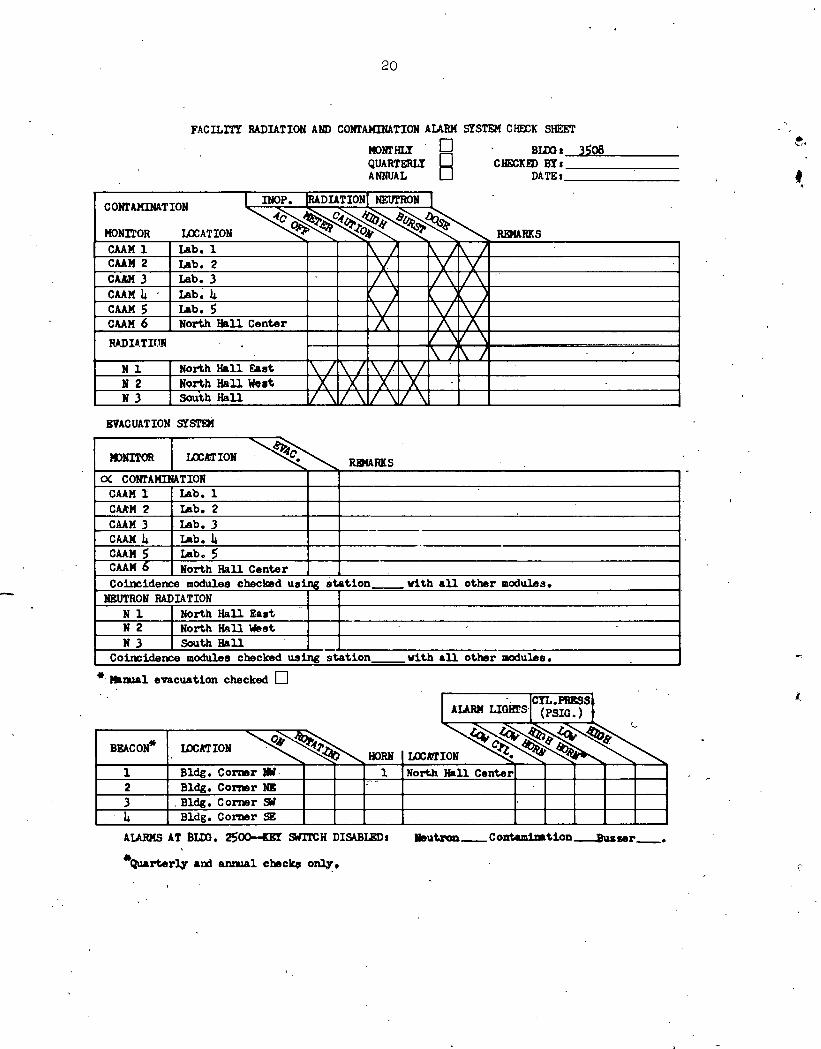
F A C I L I T Y RAI)IATION AND COHTAXIMTION A I A W SYSTEM CHECK SlEXT
mmm Bmt 3508 Q U A R T W W 0 C W K m B Y t ANNUAL DATE r
EVACUATION SYm
*. )Slwl evacuation checked
& Wrtmrly and anma1 chsc4 only,
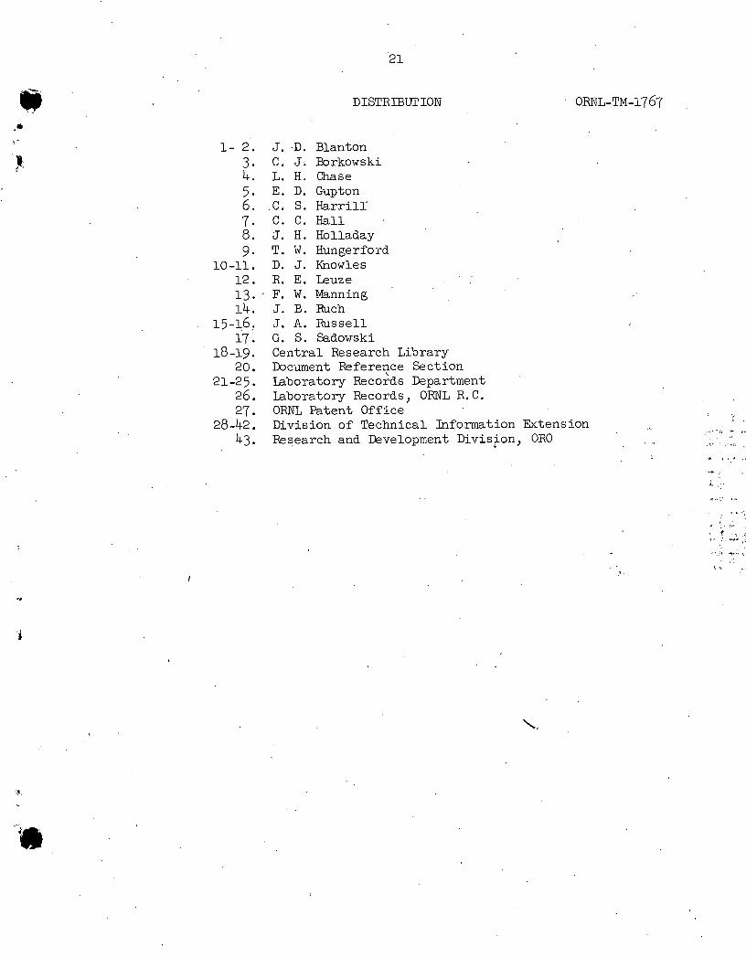
DISTRIBUTION
J. D. Blanton C. J. Porkowski L. H. Chase E. D. Gupton C . S. Harri l l ' C . C. H a l l J. H. Holladay T. W. Hungerford D. J. Knowles R. E. Leuze F. W. Manning J. E. Ruch J. A. Russell G. S. Sadowski Central Research Library Document Refe reye Section Laboratory Records Department Laboratory Records, ORNL R. C. ORNL Patent Off i c e Division of Technical Information Extension Research and Development Division, OR0
. . . . ,
t * _ , I I...
. f ' , . r . :. r",