Embed Size (px)
Citation preview
TM 5-698-6
TECHNICAL MANUAL
RELIABILITY DATA COLLECTION MANUAL FOR COMMAND,
CONTROL, COMMUNICATIONS, COMPUTER, INTELLIGENCE,
SURVEILLANCE AND RECONNAISSANCE (C4ISR)
FACILITIES
APPROVED FOR PUBLIC RELEASE: DISTRIBUTION UNLIMITED
HEADQUARTERS, DEPARTMENT OF THE ARMY 27 OCTOBER 2006
TM 5-698-6
REPRODUCTION AUTHORIZATION/RESTRICTIONS
This manual has been prepared by or for the Government and, except to the extent indicated below, is public property and not subject to copyright. Reprint or republication of this manual should include a credit substantially as follows: "Department of the Army, TM 5-698-6, Reliability Data Collection Manual for Command, Control, Communications, Computer, Intelligence, Sur-veillance, and Reconnaissance (C4ISR) Facilities, 27 October 2006."
TM 5-698-6
i
Technical Manual HEADQUARTERS No. 5-698-6 DEPARTMENT OF THE ARMY Washington, DC, 27 October 2006
APPROVED FOR PUBLIC RELEASE: DISTRIBUTION IS UNLIMITED
RELIABILITY DATA COLLECTION MANUAL FOR COMMAND, CONTROL, COMMUNICATIONS, COMPUTER, INTELLIGENCE, SURVEILLANCE, AND RECONNAISSANCE (C4ISR) FACILITIES
CONTENTS Paragraph Page CHAPTER 1. INTRODUCTION Purpose....................................................................................................... 1-1 1-1 Scope.......................................................................................................... 1-2 1-1 References.................................................................................................. 1-3 1-1 CHAPTER 2. BACKGROUND Requirements ............................................................................................. 2-1 2-1 Availability goal......................................................................................... 2-2 2-1 CHAPTER 3. RELIABILITY AND AVAILABILITY Reliability................................................................................................... 3-1 3-1 Availability ................................................................................................ 3-2 3-1 CHAPTER 4. DATA COLLECTION Required information ................................................................................. 4-1 4-1 Site identification data ............................................................................... 4-2 4-1 Site one line drawings ................................................................................ 4-3 4-1 Name plate information ............................................................................. 4-4 4-1 Critical equipment designation and sparing............................................... 4-5 4-2 Maintenance data ....................................................................................... 4-6 4-2 CHAPTER 5. DATA COLLECTION LISTINGS Description................................................................................................. 5-1 5-1 Categories and listing titles ........................................................................ 5-2 5-1 CHAPTER 6. POWER RELIABILITY ENHANCEMENT PROGRAM (PREP) ITEM
IDENTIFICATION CROSS REFERENCE GUIDE Purpose....................................................................................................... 6-1 6-1 Classification.............................................................................................. 6-1 6-1 APPENDIX A REFERENCES..................................................................................... A-1
TM 5-698-6
ii
Paragraph Page CONTENTS APPENDIX B DATA COLLECTION LISTINGS....................................................... B-1 APPENDIX C PREP ITEM IDENTIFICATION CROSS REFERENCE GUIDE ....... C-1 GLOSSARY .................................................................................................................... G-1
LIST OF TABLES
Number Title Page 5-1 Control equipment...................................................................................... 5-1 5-2 Electrical power generation and distribution equipment............................ 5-2 5-2 Heating, ventilating and air conditioning (HVAC) Equipment ................. 5-3
TM 5-698-6
1-1
CHAPTER 1 INTRODUCTION
1-1. Purpose This document provides guidance to facilities engineers responsible for site utility systems at command, control, communications, computers, intelligence, surveillance, and reconnaissance (C4ISR) facilities. This manual describes a level of data collection activities which should be performed on control, power generation and distribution, and heating, ventilating and air conditioning (HVAC) equipment for the preparation of reliability studies for operational readiness. 1-2. Scope The information in this document will describe the required information necessary to determine the reli-ability and availability of a component. Explanations and descriptions of the different metrics are also covered as well as the preferred methods. Data collection listings are also provided for various pieces of equipment to aid the data collection process. Gathering the correct information is the most vital aspect of determining accurate availability and reliability values of components. 1-3. References Appendix A contains a complete list of references used in this manual.
TM 5-698-6
2-1
CHAPTER 2 BACKGROUND
2-1. Requirements Requirements are set forth in TM 5-691, Utility Systems Design Requirements for Command, Control, Communications, Computer, Intelligence, Surveillance, and Reconnaissance (C4ISR) Facilities, for the design of optimally reliable, self contained C4ISR utility systems and for the design of conventional power and other utility services. These utility services should be capable of supplying services continu-ally to the C4ISR installation during all natural or man-made disruptions in commercial services. Poten-tial disruptions include physical attacks, biological, chemical, and radiological warfare; as well as high and low altitude nuclear blasts. 2-2. Availability goal TM 5-691 requires that each C4ISR utility system subsystem have a reliability/availability goal of 0.999999 when calculated using standard reliability techniques. Under certain assumptions this implies that each subsystem downtime will not exceed 32 seconds per year. This goal is of course contingent upon the determination of the using agency that a greater frequency of mission downtime is acceptable and therefore this goal would not apply to certain installations. Also the total reliability/availability of an installation would be dependant on the number of subsystems on site.
TM 5-698-6
3-1
CHAPTER 3 RELIABILITY and AVAILABILITY
3-1. Reliability Reliability determines the probability that a system will fail under specified use and environmental condi-tions. It is quantified by using time to failure metrics such as failure rate and mean time between failures (MTBF). Equation 1 is commonly used to calculate reliability.
Reliability (for time interval t), R(t) = e−λt (Equation 1) a. Failure rate describes the number of failures that have occurred during a specified time interval and MTBF describes the average time a unit will operate before failing. Both are calculated with the unit in the manufacturer’s specified environment. Both of these quantities are statistical metrics that are depend-ant on the failure distribution of the unit. Most manufacturers provide MTBF or failure rate for their products. b. There exists several metrics by which commercial utilities measure reliability. These metrics all measure the average availability of power to the distribution system and the utility's customer. Although these metrics are used for evaluating a utility’s system, they are not used for basic reliability modeling of non-utility systems and components. Utility metrics are customized specifically for utilities. The more common of these metrics are: (1) System average interruption frequency index (SAIFI) (2) System average interruption duration index (SAIDI) (3) Customer average interruption duration index (CAIDI) (4) Average service availability index (ASAI) 3-2. Availability Reliability and availability are often confused as being the same metric. They are related but are not the same quantity. Availability is the ability of a product or service to be ready for use when the customer wants to use it. There are several definitions of availability. Commonly used availability equations are:
Inherent availability, (Ai) = MTBF/(MTBF+MTTR) (Equation 2) Operational availability, (Ao) = MTBM/(MTBM+MDT) (Equation 3)
Where: MTBF is mean time between failures MTTR is mean time to repair MTBM is mean time between maintenance MDT is mean down time a. Inherent availability is the instantaneous probability that a component will be up. Inherent availabil-ity considers only downtime for repair due to failures. Preventative maintenance and logistics time are not included.
TM 5-698-6
3-2
b. Operational availability is the instantaneous probability that a component will be up but differs from inherent availability in that it includes all downtime. Included is downtime for both corrective mainte-nance and preventative maintenance, including any logistics delay time
TM 5-698-6
4-1
CHAPTER 4 DATA COLLECTION
4-1. Required information Five categories of information contain the necessary data for reliability modeling: Site Identification, Site One Line Drawings, Name Plate Information, Critical Equipment Designation and Sparing, and Mainte-nance Data. When combined, this information gives the analyst all the necessary data to populate a reli-ability model. Data collection for the C4ISR site is not intended to be done in a single setting nor in a single month. This is an ongoing activity that should be completed in as timely a manner as possible without impacting the readiness of the facility. Once completed, updates to the information are only nec-essary as maintenance is performed on the equipment. 4-2. Site identification data Site identification data provides basic information about the equipment and the particular C4ISR site. Site identification data consists of: a. Date of the Survey – Establishes the site configuration baseline date. b. Facility Name/ID number/Location – Identifies the facility c. Equipment Facility Name/ID – Identifies the equipment with a site specific ID number, name or lo-cation. d. In Service Date – Provides the date the equipment was installed which gives the analyst a starting point to calculate time to failure metrics. e. Parent System – Allows the equipment to be assigned to the proper site subsystem. 4-3. Site one line drawings One line drawings are used to develop the reliability block diagrams and can indicate reliability borders for the electrical distribution, pneumatic, or plumbing systems. The one line also indicates critical and redundant equipment, systems, and circuits. These drawing may also provide length of wires and pipe which are needed for the reliability models. 4-4. Nameplate information Nameplate information identifies the equipment and its specifications which allow the analyst to obtain time to failure data from the equipment manufacturer or to utilize commercial, industrial, or military fail-ure databases such as the Institute of Electronic and Electrical Engineers (IEEE) Std 493™ IEEE Recom-mended Practice for the Design of Reliable Industrial and Commercial Power Systems (Gold Book) or the US Department of the Army’s TM 5-698-5, Survey of Reliability and Availability Information for Power Distribution, Power Generation, and HVAC Components for Commercial, Industrial, and Utility Installations. Name Plate Data consists of: a Equipment Manufacturer b Equipment Model
TM 5-698-6
4-2
c Equipment Type d Equipment Ratings 4-5. Critical equipment designation and sparing Critical equipment designation and sparing data identifies equipment that is critical to the mission of the particular C4ISR site. Critical equipment must be highly reliable; generally more reliable than is practical in a single piece of equipment. This equipment generally has an automatically switched spare or a quickly replaceable spare on site. Critical equipment designation and sparing data consists of: a. Critical Equipment Designation – Identifies mission critical equipment. b. Redundant Equipment – Identifies the presence or lack of redundant equipment for critical equip-ment. c. Spares – Identifies on site critical equipment spares. 4-6. Maintenance data Maintenance data provides the reliability analyst with time to failure data as well as insight into the level of periodic maintenance performed on a piece of equipment. Time to failure data provides data for calcu-lation of time to failure metrics while periodic maintenance data allows a validation of manufacturer sup-plied failure data. This data contains both scheduled and unscheduled maintenance actions. Scheduled maintenance lists periodic maintenance while unscheduled maintenance lists equipment failures and re-pairs. Maintenance data typically exists in hand written log books or computerized maintenance records.
TM 5-698-6
5-1
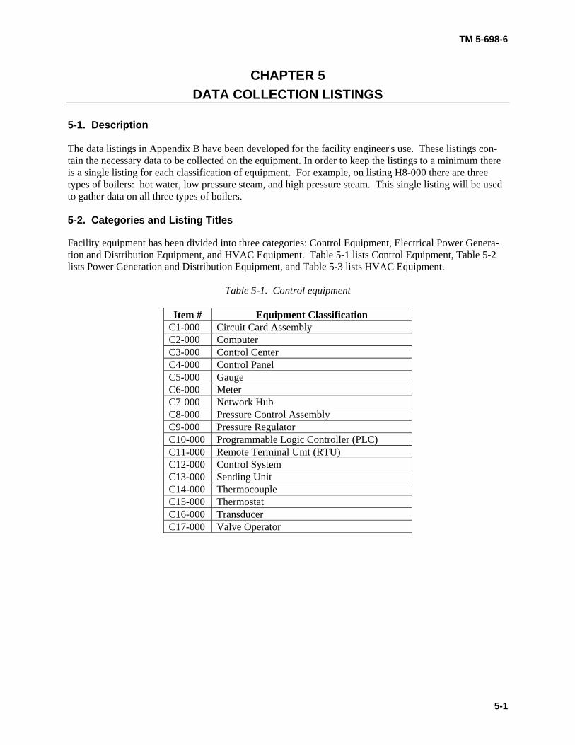
CHAPTER 5 DATA COLLECTION LISTINGS
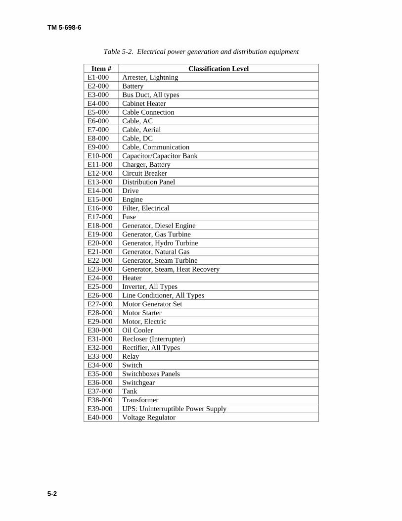
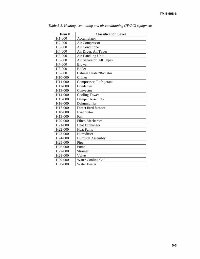
5-1. Description The data listings in Appendix B have been developed for the facility engineer's use. These listings con-tain the necessary data to be collected on the equipment. In order to keep the listings to a minimum there is a single listing for each classification of equipment. For example, on listing H8-000 there are three types of boilers: hot water, low pressure steam, and high pressure steam. This single listing will be used to gather data on all three types of boilers. 5-2. Categories and Listing Titles Facility equipment has been divided into three categories: Control Equipment, Electrical Power Genera-tion and Distribution Equipment, and HVAC Equipment. Table 5-1 lists Control Equipment, Table 5-2 lists Power Generation and Distribution Equipment, and Table 5-3 lists HVAC Equipment.
Table 5-1. Control equipment
Item # Equipment Classification C1-000 Circuit Card Assembly C2-000 Computer C3-000 Control Center C4-000 Control Panel C5-000 Gauge C6-000 Meter C7-000 Network Hub C8-000 Pressure Control Assembly C9-000 Pressure Regulator C10-000 Programmable Logic Controller (PLC) C11-000 Remote Terminal Unit (RTU) C12-000 Control System C13-000 Sending Unit C14-000 Thermocouple C15-000 Thermostat C16-000 Transducer C17-000 Valve Operator
TM 5-698-6
5-2
Table 5-2. Electrical power generation and distribution equipment
Item # Classification Level E1-000 Arrester, Lightning E2-000 Battery E3-000 Bus Duct, All types E4-000 Cabinet Heater E5-000 Cable Connection E6-000 Cable, AC E7-000 Cable, Aerial E8-000 Cable, DC E9-000 Cable, Communication E10-000 Capacitor/Capacitor Bank E11-000 Charger, Battery E12-000 Circuit Breaker E13-000 Distribution Panel E14-000 Drive E15-000 Engine E16-000 Filter, Electrical E17-000 Fuse E18-000 Generator, Diesel Engine E19-000 Generator, Gas Turbine E20-000 Generator, Hydro Turbine E21-000 Generator, Natural Gas E22-000 Generator, Steam Turbine E23-000 Generator, Steam, Heat Recovery E24-000 Heater E25-000 Inverter, All Types E26-000 Line Conditioner, All Types E27-000 Motor Generator Set E28-000 Motor Starter E29-000 Motor, Electric E30-000 Oil Cooler E31-000 Recloser (Interrupter) E32-000 Rectifier, All Types E33-000 Relay E34-000 Switch E35-000 Switchboxes Panels E36-000 Switchgear E37-000 Tank E38-000 Transformer E39-000 UPS: Uninterruptible Power Supply E40-000 Voltage Regulator
TM 5-698-6
5-3
Table 5-3. Heating, ventilating and air conditioning (HVAC) equipment
Item # Classification Level H1-000 Accumulator H2-000 Air Compressor H3-000 Air Conditioner H4-000 Air Dryer, All Types H5-000 Air Handling Unit H6-000 Air Separator, All Types H7-000 Blower H8-000 Boiler H9-000 Cabinet Heater/Radiator H10-000 Chiller H11-000 Compressor, Refrigerant H12-000 Condenser H13-000 Convector H14-000 Cooling Tower H15-000 Damper Assembly H16-000 Dehumidifier H17-000 Direct fired furnace H18-000 Evaporator H19-000 Fan H20-000 Filter, Mechanical H21-000 Heat Exchanger H22-000 Heat Pump H23-000 Humidifier H24-000 Humistat Assembly H25-000 Pipe H26-000 Pump H27-000 Strainer H28-000 Valve H29-000 Water Cooling Coil H30-000 Water Heater
TM 5-698-6
6-1
CHAPTER 6 POWER RELIABILITY ENHANCEMENT PROGRAM (PREP) ITEM
IDENTIFICATION CROSS REFERENCE GUIDE 6-1. Purpose The PREP Item Cross Reference Guide in appendix C is supplied to help cross reference the new item numbers currently being used to the previous component identification of kind numbers. a. This alteration was needed because the prior component identification numbering system made it difficult to categorize similar components under a like classification in a hierarchical structure. The de-sign of the prior component identification numbering system made it impossible to add a new component, which was similar to other components other than in size or capacity, to a like group of numbers. b. The previous component identification system also made it difficult to roll up like classes into a more generic classification of a component. This can be explained better by providing an example of ca-bles in different classifications based on size and application. Three different types of cable: (1) AC cable, above ground, 0-600volts, in conduit, item #E6-111 (2) AC cable, above ground, 0-600volts, in trays, item #E6-112 (3) AC cable, above ground, 0-600volts, no conduit, item #E6-113 c. All three of these classes can have their own failure rates, availability numbers ...etc. But if the ana-lyst did not have either of these specific classifications known to him, a generic failure rate could be ob-tained by "rolling up" one level to AC cable, above ground, 0-600 volts, item #E6-110 using the next level of "Item #'s" for AC cable. This "rolling up" process can keep going up one more level getting more and more generic all the way up to AC Cable, item #E6-000. 6-2. Classifications All new assigned PREP identifications have a letter classifications provided that breaks out the Power Generation, Distribution and Electrical component by adding the prefix "E" to the item number. It also separates the HVAC components with the prefix "H" and the Controls and Monitoring components with the prefix "C". This can make sorting through the entire list of components a lot less cumbersome. a. Although the prefixes provide a big advantage to cataloging the components, there were some com-ponents that could possibly fall within two different categories (i.e., Power Generation and HVAC). Some of these components are listed below at the "highest level" along with their Item Number.
1. Cabinet Heater #E4-000 2. Engine #E15-000 3. Heater #E24-000 4. Oil Cooler #E30-000 5. Tank #E37-000
TM 5-698-6
6-2
b. These items could have been categorized in HVAC as well, but do to their association with power generation components (i.e., Engine, Diesel) it was decided to categorize them with the prefix "E". Therefore, it may be necessary to look in both categories.
TM 5-698-6
A-1
APPENDIX A
REFERENCES
Required Publications Government Publications: US Army Corps of Engineers (USACE)
TM 5-691, Utility Systems Design Requirements for Command, Control, Communications, Computer, Intelligence, Surveillance, and Reconnaissance (C4ISR) Facilities, 15 December 2000. (cited in paragraphs 2-1 and 2-2). TM 5-698-5, Survey of Reliability and Availability Information for Power Distribution, Power Gen-eration, and HVAC Components for Commercial, Industrial, and Utility Installations. (cited in para-graph 4-4).
Non-Government Publications: Institute of Electronic and Electrical Engineers (IEEE) Std 493™ IEEE Recommended Practice for the Design of Reliable Industrial and Commercial Power Systems (Gold Book). (cited in paragraph 4-4)
Related Publications Government Publications:
MIL-STD-3007B, Standard Practice for Unified Facilities Criteria and Unified Facilities Guide Specifications
Air Force Civil Engineering Support Agency (AFCESA)
AFH32-1282V2.pdf, Field Guide for Inspection, Evaluation, and Maintenance Criteria for Elec-trical Transformers
AFH 32-1282V1.pdf, Field Guide for Inspection, Evaluation and Maintenance Criteria for Elec-trical Substations and Switchgear
AFI 32-1062, Electrical Power Plants and Generators AFI 32-1063, Electrical Power Systems
US Army Corps of Engineers (USACE)
ARMY TM 5-683 NAVY NAVFAC MO-116 AIR FORCE AFJMAN 32-1083, Facilities Engineering Electrical Interior Facilities.
TM 5-698-6
A-2
ARMY TM 5-684 NAVY NAVFAC MO-200 AIR FORCE AFJMAN 32-1082, Facilities Engineering Electrical Exterior Facilities TM 5-688, Foreign Voltages and Frequencies Guide TM 5-692-1, Maintenance of Mechanical and Electrical Equipment at Command, Control, Com-puters, Communications, Intelligence, Surveillance, and Reconnaissance (C4ISR) Facilities, Recom-mended Maintenance Practices. TM 5-692-2, Maintenance of Mechanical and Electrical Equipment at Command, Control, Com-puters, Communications, Intelligence, Surveillance, and Reconnaissance (C4ISR) Facilities, System Design Features. TM 5-693, Uninterruptible Power Supply System Selection, Installation, and Maintenance for Com-mand, Control, Communications, Computers, Intelligence, Surveillance, and Reconnaissance (C4ISR) Facilities.
ARMY TM 5-811-1 AIR FORCE AFJMAN 32-1080, Electrical Power Supply and Distribution
Non-Government Publications:
Arthur D. Little, "Reliability and Distributed Generation", White Paper
Carnegie Mellon Electricity Industry Center (CEIC), "Electricity under Stress: Robustness and Eco-nomics of Distributed Generation" EPRI Corp., "Reliability of Electric Utility Distribution Systems: EPRI White Paper" IEEE "Calculating Electrical Risk and Reliability", Paper No. PCIC 94-3, John Propst, Senior Mem-ber, IEEE, Shell Development Company, Houston, TX 77251-1380 IEEE "Power Quality Monitoring for High Reliability Systems", Ross Ignall – Dranetz BMI, Mark McGranaghan, Electrotek Concepts, Mark Figor – DHL John Propst, Equilon Enterprises, LLC, "Operating Manual for Calculating Electrical Risk and Reli-ability Using the 2000-2 PCIC Reliability Model" North American Reliability Council, "NERC Reliability Standards Process Manual" North American Reliability Council, "The NERC Functional Model - Functions and Relationships for Interconnected Systems Operation and Planning"
SAS Institute, "New Methods for Modeling Reliability Using Degradation Data"
TM 5-698-6
B-1
APPENDIX B
DATA COLLECTION LISTINGS
CATEGORY C: Control Equipment C1-000. Circuit Card Assembly The following is a listing of the information to collect to aid in the development of reliability metrics for a Circuit Card Assembly:
Today’s Date Facility Name/ID Equipment Facility ID/Name Manufacturer Model Serial Number In Service Date Parent system Is this device critical? Is there a spare on site for this device? If so, How Many? What is the approximate time to replace this device? Is there a redundant device available? Are records kept on maintenance and replacement? Are they written or computerized? What periodic maintenance is performed and at what interval? Has this device or any components been replaced due to failure?
TM 5-698-6
B-2
C2-000. Computer The following is a listing of the information to collect to aid in the development of reliability metrics for a Computer:
Today’s Date Facility Name/ID Equipment Facility ID/Name Manufacturer Model Serial Number In Service Date Parent system Type: PC Workstation or Control System Server Is this device critical? Is there a spare on site for this device? If so, How Many? What is the approximate time to replace this device? Is there a redundant device available? Are records kept on maintenance and replacement? Are they written or computerized? What periodic maintenance is performed and at what interval? Has this device or any components been replaced due to failure?
TM 5-698-6
B-3
C3-000. Control Center, Motor The following is a listing of the information to collect to aid in the development of reliability metrics for a Motor Control Center:
Today’s Date Facility Name/ID Equipment Facility ID/Name Manufacturer Model Serial Number In Service Date Parent system Type: motor center / load center Ratings:
Voltage Current
Is this device critical? Is there a spare on site for this device? If so, How Many? What is the approximate time to replace this device? Is there a redundant device available? Are records kept on maintenance and replacement? Are they written or computerized? What periodic maintenance is performed and at what interval? Has this device or any components been replaced due to failure?
TM 5-698-6
B-4
C4-000. Control Panel The following is a listing of the information to collect to aid in the development of reliability metrics for a Control Panel:
Today’s Date Facility Name/ID Equipment Facility ID/Name Manufacturer Model Serial Number In Service Date Parent system Use: Generator, HVAC/Chillers/AHUs, Switchgear Is this control panel for critical equipment? Is there a spare on site for this device? If so, How Many? What is the approximate time to replace this device? Is there a redundant Control Panel available? Are records kept on maintenance and replacement? Are they written or computerized? What periodic maintenance is performed and at what interval? Has this device or any components been replaced due to failure?
TM 5-698-6
B-5
C5-000. Gauge The following is a listing of the information to collect to aid in the development of reliability metrics for a Gauge:
Today’s Date Facility Name/ID Equipment Facility ID/Name Manufacturer Model In Service Date Parent system Type: Fuel (Diesel, Gasoline, or Heating Oil?), Vacuum, Pressure (Hydraulic or Pneumatic?) Does this Gauge monitor a critical device? Is there a spare on site for this device? If so, How Many? What is the approximate time to replace this device? Is there a redundant Gauge available? Are records kept on maintenance and replacement? Are they written or computerized? What periodic maintenance is performed and at what interval? Has this device been replaced due to failure?
TM 5-698-6
B-6
C6-000. Meter The following is a listing of the information to collect to aid in the development of reliability metrics for a Meter:
Today’s Date Facility Name/ID Equipment Facility ID/Name Manufacturer Model Serial Number In Service Date Parent system Type: Electric, Fuel, or Water
Digital or Analog Does this Meter monitor a critical device? Is there a spare on site for this device? If so, How Many? What is the approximate time to replace this device? Is there a redundant Meter available? Are records kept on maintenance and replacement? Are they written or computerized? What periodic maintenance or calibration is performed and at what interval? Has this device been replaced due to failure?
TM 5-698-6
B-7
C7-000. Network Hub The following is a listing of the information to collect to aid in the development of reliability metrics for a Network Hub:
Today’s Date Facility Name/ID Equipment Facility ID/Name Manufacturer Model Serial Number In Service Date Parent system Type: Ethernet or Fiber Optic Is this device critical? Is there a spare on site for this device? If so, How Many? What is the approximate time to replace this device? Is there a redundant device available? Are records kept on maintenance and replacement? Are they written or computerized? What periodic maintenance is performed and at what interval? Has this device or any components been replaced due to failure?
TM 5-698-6
B-8
C8-000. Pressure Control Assembly The following is a listing of the information to collect to aid in the development of reliability metrics for a Pressure Control Assembly:
Today’s Date Facility Name/ID Equipment Facility ID/Name Manufacturer Model Serial Number In Service Date Parent system Ratings:
Maximum Pressure (psi) Accumulator Capacity (gal) Is this Pressure Control critical equipment? Is there a spare on site for this device? If so, How Many? What is the approximate time to replace this device? Is there a redundant Pressure Control available? Are records kept on maintenance and replacement? Are they written or computerized? What periodic maintenance is performed and at what interval? Has this device or any components been replaced due to failure?
TM 5-698-6
B-9
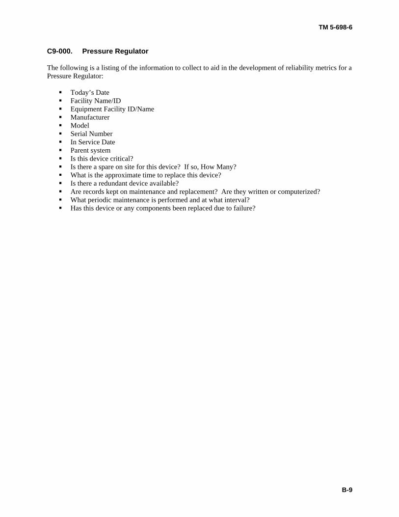
C9-000. Pressure Regulator The following is a listing of the information to collect to aid in the development of reliability metrics for a Pressure Regulator:
Today’s Date Facility Name/ID Equipment Facility ID/Name Manufacturer Model Serial Number In Service Date Parent system Is this device critical? Is there a spare on site for this device? If so, How Many? What is the approximate time to replace this device? Is there a redundant device available? Are records kept on maintenance and replacement? Are they written or computerized? What periodic maintenance is performed and at what interval? Has this device or any components been replaced due to failure?
TM 5-698-6
B-10
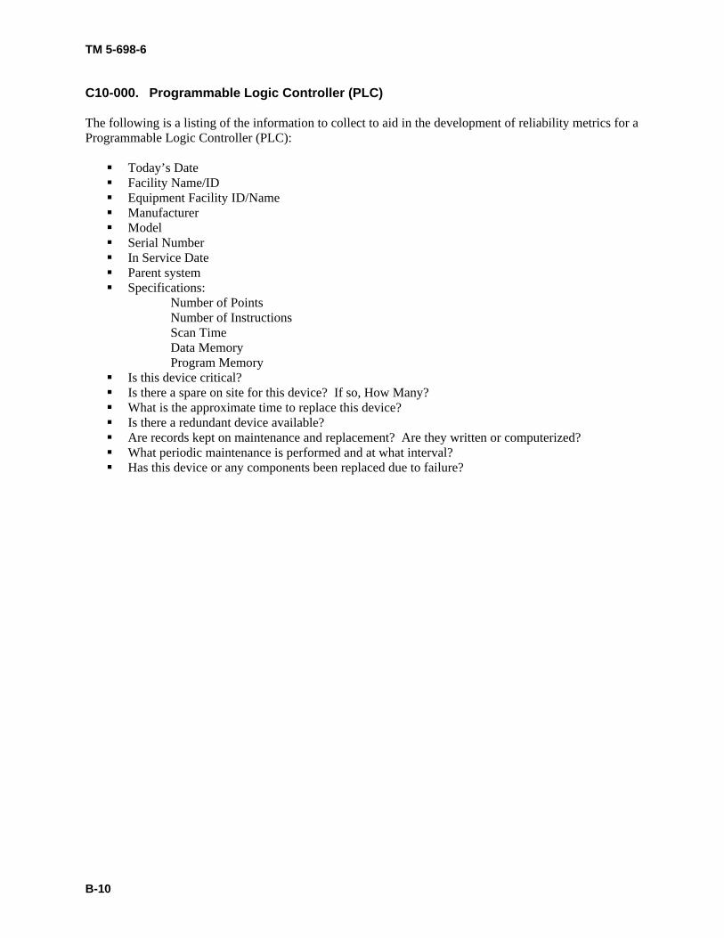
C10-000. Programmable Logic Controller (PLC) The following is a listing of the information to collect to aid in the development of reliability metrics for a Programmable Logic Controller (PLC):
Today’s Date Facility Name/ID Equipment Facility ID/Name Manufacturer Model Serial Number In Service Date Parent system Specifications:
Number of Points Number of Instructions Scan Time Data Memory Program Memory
Is this device critical? Is there a spare on site for this device? If so, How Many? What is the approximate time to replace this device? Is there a redundant device available? Are records kept on maintenance and replacement? Are they written or computerized? What periodic maintenance is performed and at what interval? Has this device or any components been replaced due to failure?
TM 5-698-6
B-11
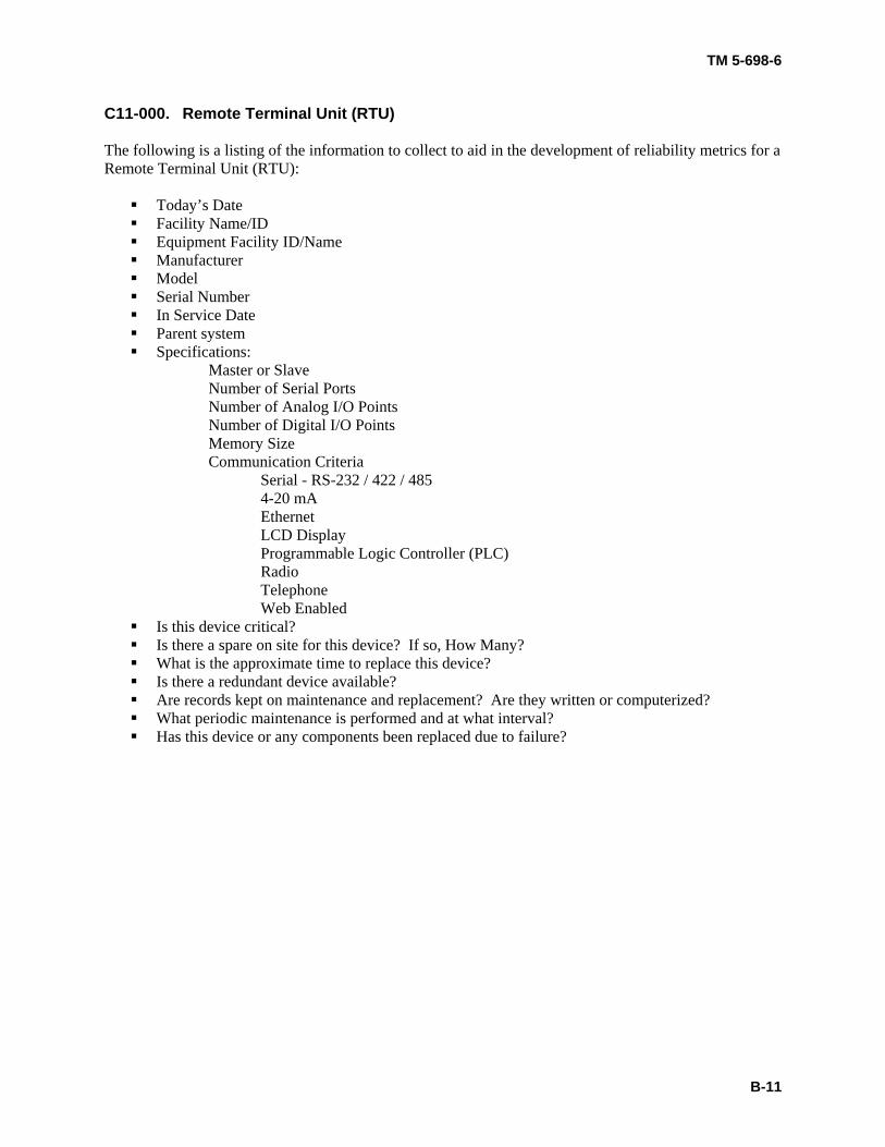
C11-000. Remote Terminal Unit (RTU) The following is a listing of the information to collect to aid in the development of reliability metrics for a Remote Terminal Unit (RTU):
Today’s Date Facility Name/ID Equipment Facility ID/Name Manufacturer Model Serial Number In Service Date Parent system Specifications:
Master or Slave Number of Serial Ports Number of Analog I/O Points Number of Digital I/O Points Memory Size Communication Criteria Serial - RS-232 / 422 / 485 4-20 mA Ethernet LCD Display Programmable Logic Controller (PLC) Radio
Telephone Web Enabled
Is this device critical? Is there a spare on site for this device? If so, How Many? What is the approximate time to replace this device? Is there a redundant device available? Are records kept on maintenance and replacement? Are they written or computerized? What periodic maintenance is performed and at what interval? Has this device or any components been replaced due to failure?
TM 5-698-6
B-12
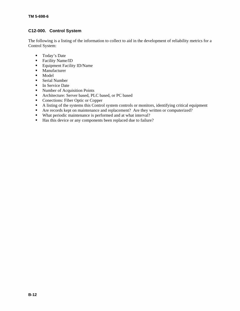
C12-000. Control System The following is a listing of the information to collect to aid in the development of reliability metrics for a Control System:
Today’s Date Facility Name/ID Equipment Facility ID/Name Manufacturer Model Serial Number In Service Date Number of Acquisition Points Architecture: Server based, PLC based, or PC based Conections: Fiber Optic or Copper A listing of the systems this Control system controls or monitors, identifying critical equipment Are records kept on maintenance and replacement? Are they written or computerized? What periodic maintenance is performed and at what interval? Has this device or any components been replaced due to failure?
TM 5-698-6
B-13
C13-000. Sending Unit The following is a listing of the information to collect to aid in the development of reliability metrics for a Sending Unit:
Today’s Date Facility Name/ID Equipment Facility ID/Name Manufacturer Model Serial Number In Service Date Parent system Use: Air Velocity, Pressure, or Temperature Is this device critical? Is there a spare on site for this device? If so, How Many? What is the approximate time to replace this device? Is there a redundant device available? Are records kept on maintenance and replacement? Are they written or computerized? What periodic maintenance is performed and at what interval? Has this device or any components been replaced due to failure?
TM 5-698-6
B-14
C14-000. Thermocouple The following is a listing of the information to collect to aid in the development of reliability metrics for a Thermocouple:
Today’s Date Facility Name/ID Equipment Facility ID/Name Manufacturer Model Serial Number In Service Date Parent system Is this device critical? Is there a spare on site for this device? If so, How Many? What is the approximate time to replace this device? Is there a redundant device available? Are records kept on maintenance and replacement? Are they written or computerized? What periodic maintenance is performed and at what interval? Has this device or any components been replaced due to failure?
TM 5-698-6
B-15
C15-000. Thermostat The following is a listing of the information to collect to aid in the development of reliability metrics for a Thermostat:
Today’s Date Facility Name/ID Equipment Facility ID/Name Manufacturer Model Serial Number In Service Date Parent system Type: Electronic, Millivolt, 24Vac Use: Heating or Heating & Cooling Is there a battery backup? Does this Thermostat control critical equipment? Is there a spare on site for this device? If so, How Many? What is the approximate time to replace this device? Is there a redundant Thermostat available? Are records kept on maintenance and replacement? Are they written or computerized? What periodic maintenance is performed and at what interval? Has this device or any components been replaced due to failure?
TM 5-698-6
B-16
C16-000. Transducer The following is a listing of the information to collect to aid in the development of reliability metrics for a Transducer:
Today’s Date Facility Name/ID Equipment Facility ID/Name Manufacturer Model Serial Number In Service Date Parent system Type: Flow, Temperature, Pressure, or Vacuum Ratings:
Maximum Operating Temperature (oC or oF) Maximum Operating Pressure (psi) Maximum Operating Vacuum (mmHg) Maximum Operating Flow (GPM) Operating Voltage AC (VAC) DC (VDC) Output Voltage AC (VAC) DC (VDC) Does this Transducer control critical equipment? Is there a spare on site for this device? If so, How Many? What is the approximate time to replace this device? Is there a redundant Transducer available? Are records kept on maintenance and replacement? Are they written or computerized? What periodic maintenance is performed and at what interval? Has this device or any components been replaced due to failure?

TM 5-698-6
B-17
C17-000. Valve Operator The following is a listing of the information to collect to aid in the development of reliability metrics for a Valve Operator:
Today’s Date Facility Name/ID Equipment Facility ID/Name Manufacturer Model Serial Number In Service Date Parent system Type: Electric, Hydraulic, or Pneumatic Is this device critical? Is there a spare on site for this device? If so, How Many? What is the approximate time to replace this device? Is there a redundant device available? Are records kept on maintenance and replacement? Are they written or computerized? What periodic maintenance is performed and at what interval? Has this device or any components been replaced due to failure?
TM 5-698-6
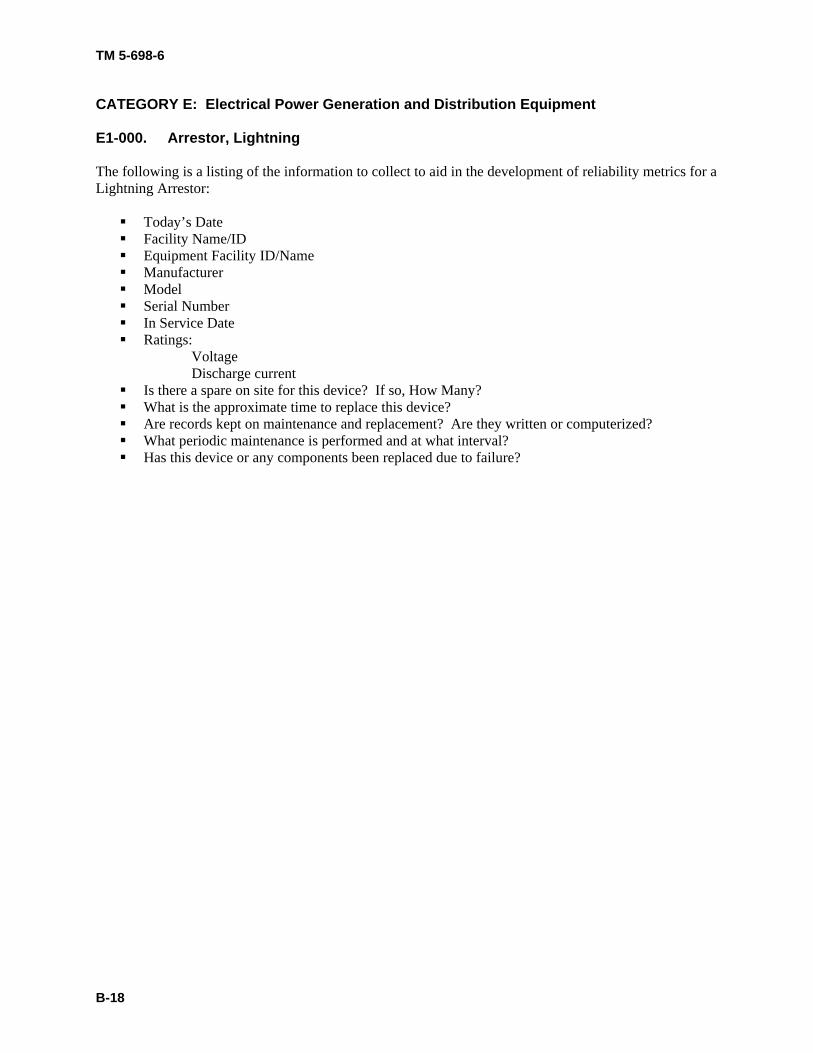
B-18
CATEGORY E: Electrical Power Generation and Distribution Equipment E1-000. Arrestor, Lightning The following is a listing of the information to collect to aid in the development of reliability metrics for a Lightning Arrestor:
Today’s Date Facility Name/ID Equipment Facility ID/Name Manufacturer Model Serial Number In Service Date Ratings:
Voltage Discharge current
Is there a spare on site for this device? If so, How Many? What is the approximate time to replace this device? Are records kept on maintenance and replacement? Are they written or computerized? What periodic maintenance is performed and at what interval? Has this device or any components been replaced due to failure?
TM 5-698-6
B-19
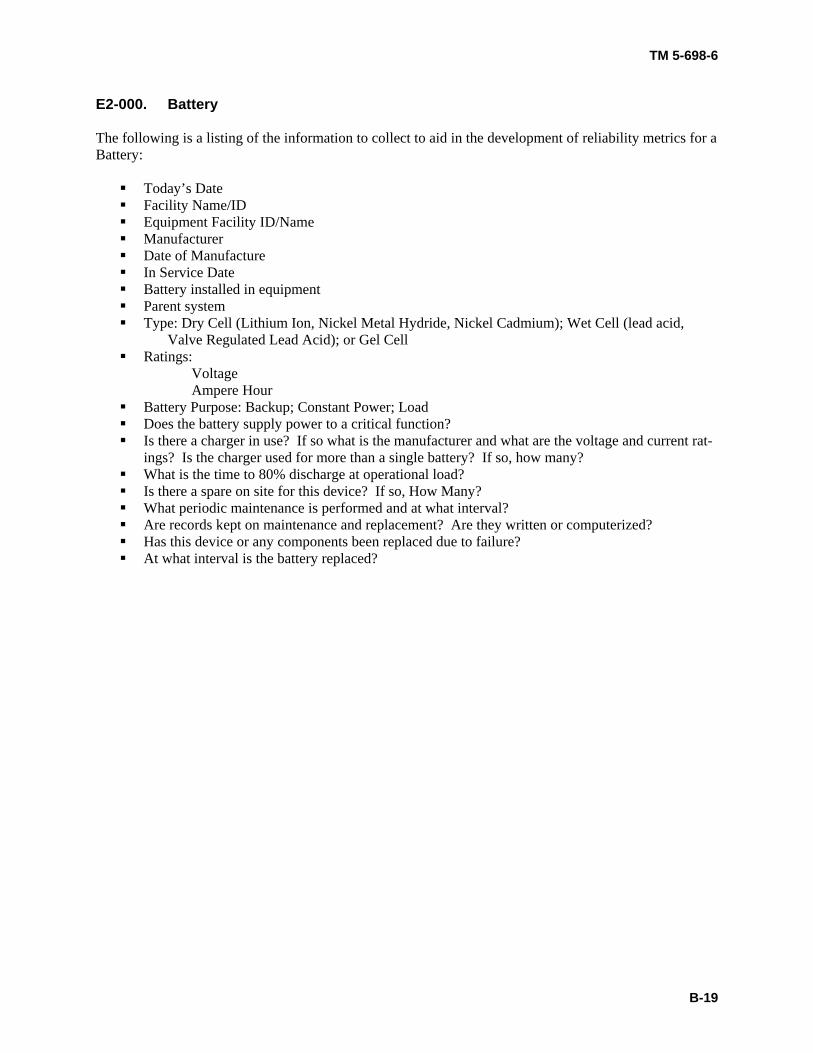
E2-000. Battery The following is a listing of the information to collect to aid in the development of reliability metrics for a Battery:
Today’s Date Facility Name/ID Equipment Facility ID/Name Manufacturer Date of Manufacture In Service Date Battery installed in equipment Parent system Type: Dry Cell (Lithium Ion, Nickel Metal Hydride, Nickel Cadmium); Wet Cell (lead acid,
Valve Regulated Lead Acid); or Gel Cell Ratings:
Voltage Ampere Hour
Battery Purpose: Backup; Constant Power; Load Does the battery supply power to a critical function? Is there a charger in use? If so what is the manufacturer and what are the voltage and current rat-
ings? Is the charger used for more than a single battery? If so, how many? What is the time to 80% discharge at operational load? Is there a spare on site for this device? If so, How Many? What periodic maintenance is performed and at what interval? Are records kept on maintenance and replacement? Are they written or computerized? Has this device or any components been replaced due to failure? At what interval is the battery replaced?
TM 5-698-6
B-20
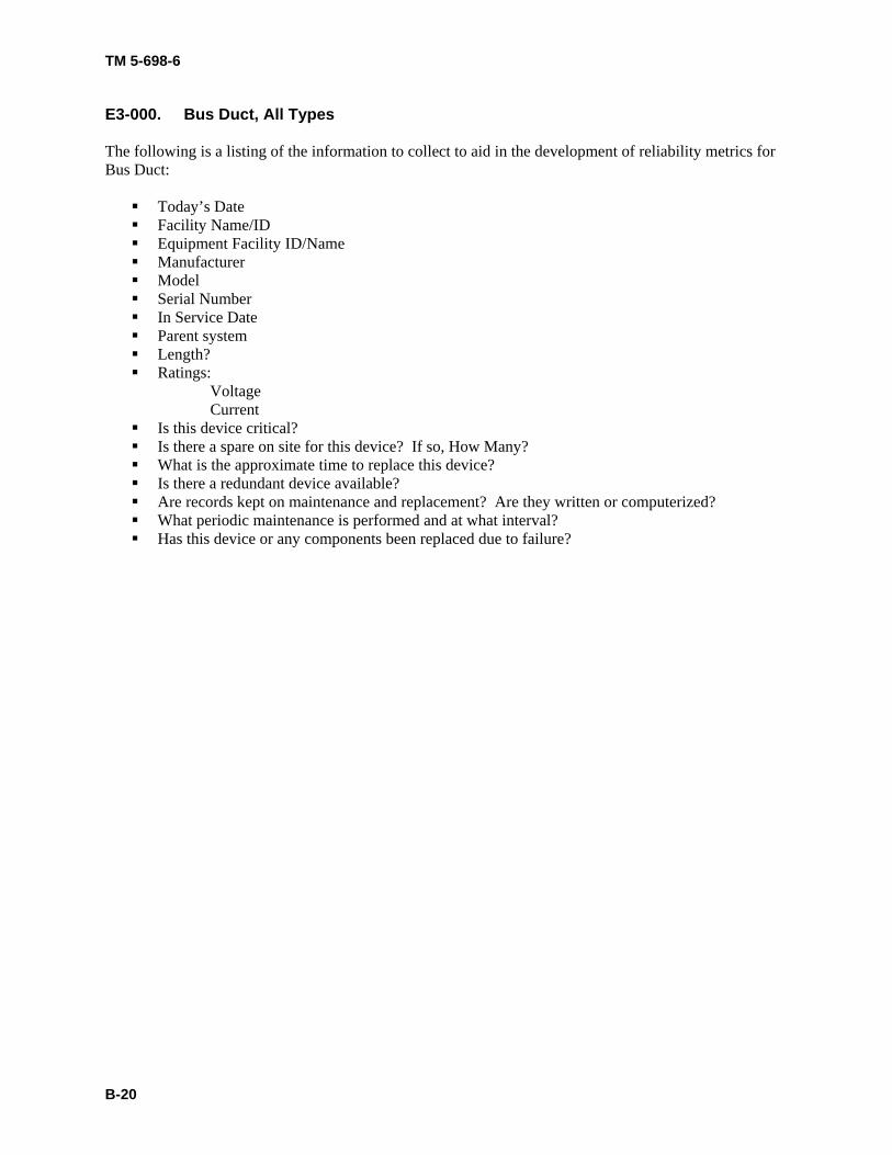
E3-000. Bus Duct, All Types The following is a listing of the information to collect to aid in the development of reliability metrics for Bus Duct:
Today’s Date Facility Name/ID Equipment Facility ID/Name Manufacturer Model Serial Number In Service Date Parent system Length? Ratings:
Voltage Current
Is this device critical? Is there a spare on site for this device? If so, How Many? What is the approximate time to replace this device? Is there a redundant device available? Are records kept on maintenance and replacement? Are they written or computerized? What periodic maintenance is performed and at what interval? Has this device or any components been replaced due to failure?
TM 5-698-6
B-21
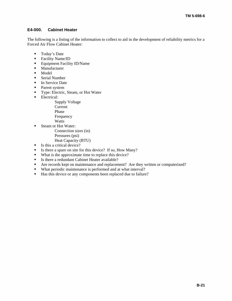
E4-000. Cabinet Heater The following is a listing of the information to collect to aid in the development of reliability metrics for a Forced Air Flow Cabinet Heater:
Today’s Date Facility Name/ID Equipment Facility ID/Name Manufacturer Model Serial Number In Service Date Parent system Type: Electric, Steam, or Hot Water Electrical:
Supply Voltage Current Phase Frequency Watts Steam or Hot Water:
Connection sizes (in) Pressures (psi) Heat Capacity (BTU) Is this a critical device? Is there a spare on site for this device? If so, How Many? What is the approximate time to replace this device? Is there a redundant Cabinet Heater available? Are records kept on maintenance and replacement? Are they written or computerized? What periodic maintenance is performed and at what interval? Has this device or any components been replaced due to failure?
TM 5-698-6
B-22
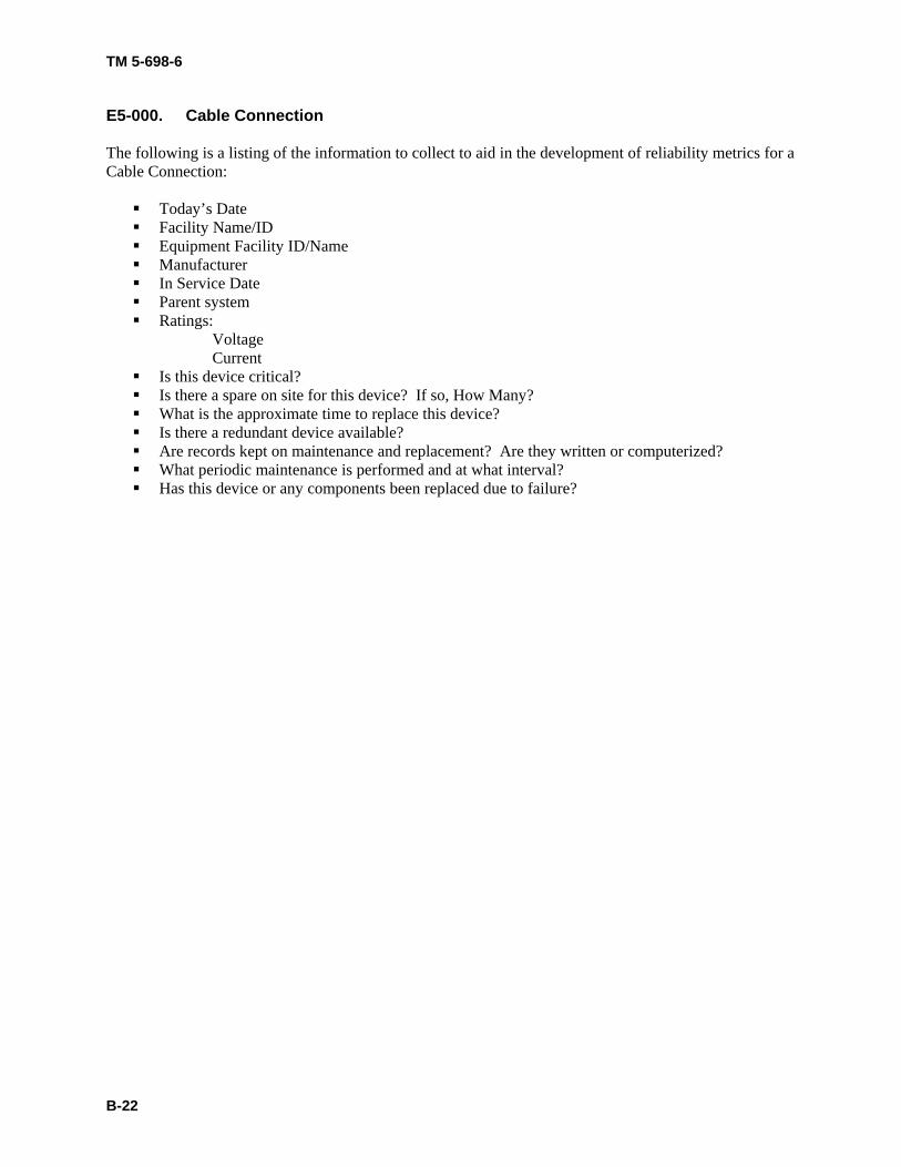
E5-000. Cable Connection The following is a listing of the information to collect to aid in the development of reliability metrics for a Cable Connection:
Today’s Date Facility Name/ID Equipment Facility ID/Name Manufacturer In Service Date Parent system Ratings:
Voltage Current
Is this device critical? Is there a spare on site for this device? If so, How Many? What is the approximate time to replace this device? Is there a redundant device available? Are records kept on maintenance and replacement? Are they written or computerized? What periodic maintenance is performed and at what interval? Has this device or any components been replaced due to failure?
TM 5-698-6
B-23
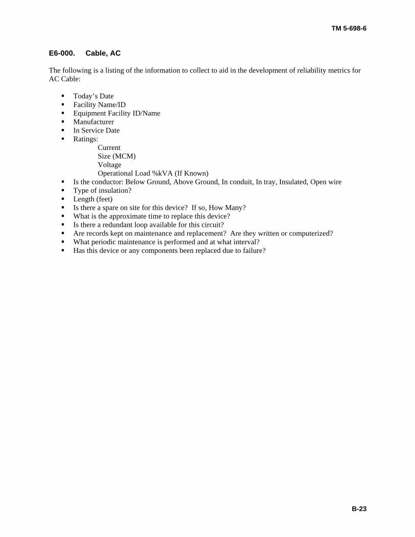
E6-000. Cable, AC The following is a listing of the information to collect to aid in the development of reliability metrics for AC Cable:
Today’s Date Facility Name/ID Equipment Facility ID/Name Manufacturer In Service Date Ratings:
Current Size (MCM) Voltage Operational Load %kVA (If Known)
Is the conductor: Below Ground, Above Ground, In conduit, In tray, Insulated, Open wire Type of insulation? Length (feet) Is there a spare on site for this device? If so, How Many? What is the approximate time to replace this device? Is there a redundant loop available for this circuit? Are records kept on maintenance and replacement? Are they written or computerized? What periodic maintenance is performed and at what interval? Has this device or any components been replaced due to failure?
TM 5-698-6
B-24
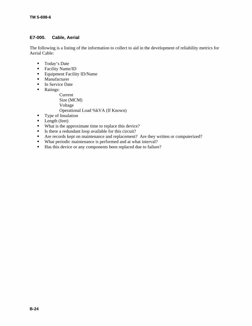
E7-000. Cable, Aerial The following is a listing of the information to collect to aid in the development of reliability metrics for Aerial Cable:
Today’s Date Facility Name/ID Equipment Facility ID/Name Manufacturer In Service Date Ratings:
Current Size (MCM) Voltage Operational Load %kVA (If Known)
Type of Insulation Length (feet) What is the approximate time to replace this device? Is there a redundant loop available for this circuit? Are records kept on maintenance and replacement? Are they written or computerized? What periodic maintenance is performed and at what interval? Has this device or any components been replaced due to failure?
TM 5-698-6
B-25
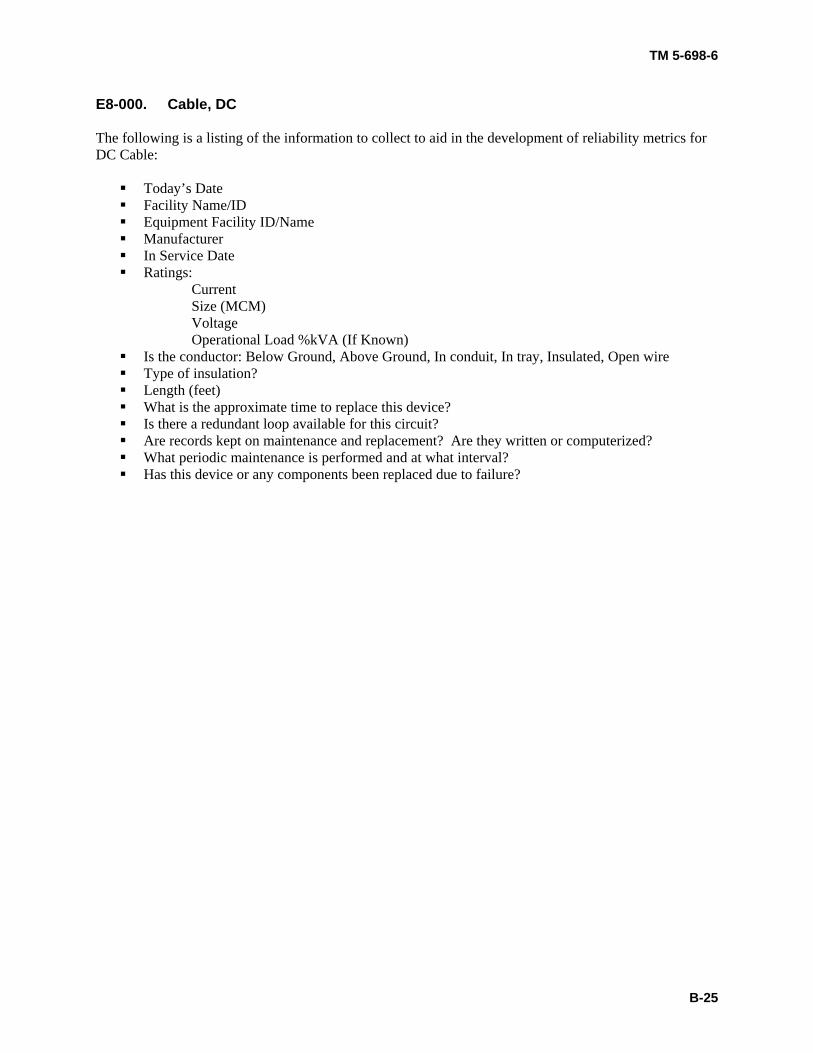
E8-000. Cable, DC The following is a listing of the information to collect to aid in the development of reliability metrics for DC Cable:
Today’s Date Facility Name/ID Equipment Facility ID/Name Manufacturer In Service Date Ratings:
Current Size (MCM) Voltage Operational Load %kVA (If Known)
Is the conductor: Below Ground, Above Ground, In conduit, In tray, Insulated, Open wire Type of insulation? Length (feet) What is the approximate time to replace this device? Is there a redundant loop available for this circuit? Are records kept on maintenance and replacement? Are they written or computerized? What periodic maintenance is performed and at what interval? Has this device or any components been replaced due to failure?
TM 5-698-6
B-26
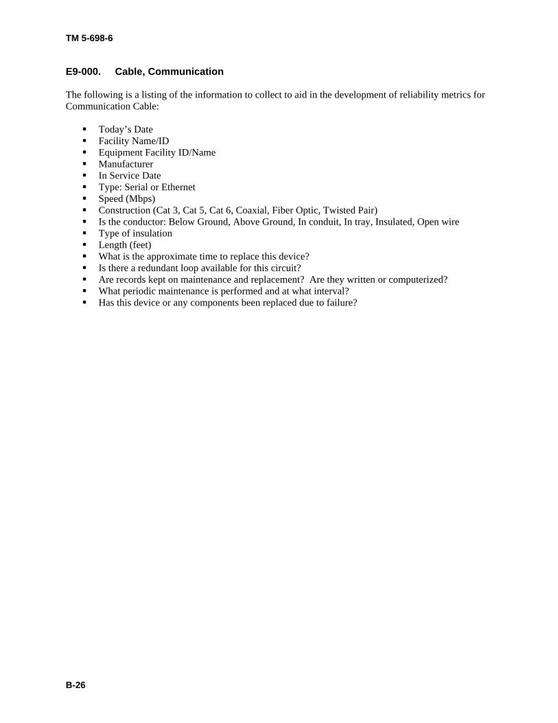
E9-000. Cable, Communication The following is a listing of the information to collect to aid in the development of reliability metrics for Communication Cable:
Today’s Date Facility Name/ID Equipment Facility ID/Name Manufacturer In Service Date Type: Serial or Ethernet Speed (Mbps) Construction (Cat 3, Cat 5, Cat 6, Coaxial, Fiber Optic, Twisted Pair) Is the conductor: Below Ground, Above Ground, In conduit, In tray, Insulated, Open wire Type of insulation Length (feet) What is the approximate time to replace this device? Is there a redundant loop available for this circuit? Are records kept on maintenance and replacement? Are they written or computerized? What periodic maintenance is performed and at what interval? Has this device or any components been replaced due to failure?
TM 5-698-6
B-27
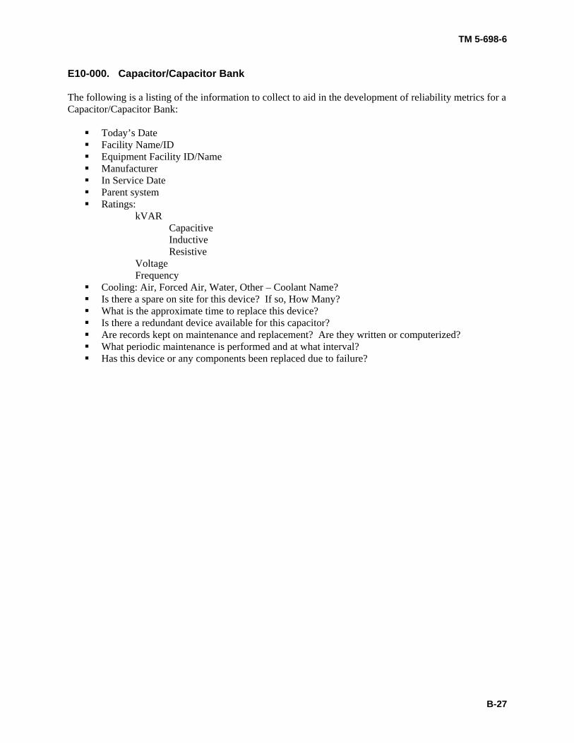
E10-000. Capacitor/Capacitor Bank
The following is a listing of the information to collect to aid in the development of reliability metrics for a Capacitor/Capacitor Bank:
Today’s Date Facility Name/ID Equipment Facility ID/Name Manufacturer In Service Date Parent system Ratings:
kVAR Capacitive Inductive Resistive Voltage Frequency
Cooling: Air, Forced Air, Water, Other – Coolant Name? Is there a spare on site for this device? If so, How Many? What is the approximate time to replace this device? Is there a redundant device available for this capacitor? Are records kept on maintenance and replacement? Are they written or computerized? What periodic maintenance is performed and at what interval? Has this device or any components been replaced due to failure?
TM 5-698-6
B-28
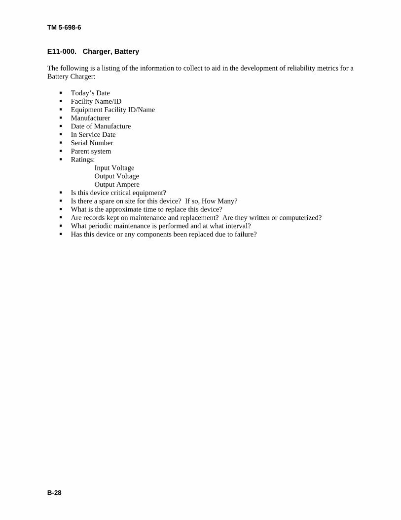
E11-000. Charger, Battery The following is a listing of the information to collect to aid in the development of reliability metrics for a Battery Charger:
Today’s Date Facility Name/ID Equipment Facility ID/Name Manufacturer Date of Manufacture In Service Date Serial Number Parent system Ratings:
Input Voltage Output Voltage Output Ampere
Is this device critical equipment? Is there a spare on site for this device? If so, How Many? What is the approximate time to replace this device? Are records kept on maintenance and replacement? Are they written or computerized? What periodic maintenance is performed and at what interval? Has this device or any components been replaced due to failure?

TM 5-698-6
B-29
E12-000. Circuit Breaker The following is a listing of the information to collect to aid in the development of reliability metrics for a Circuit Breaker:
Today’s Date Facility Name/ID Equipment Facility ID/Name Manufacturer In Service Date Parent system Type: Fixed, Metal Clad, Molded Case, Oil filled, SF6 Filled, Vacuum Is this circuit breaker normally open or normally closed? Ratings:
Voltage Current Number of Poles Interrupting Capacity Frame Size
Is there a spare on site for this device? If so, How Many? What is the approximate time to replace this device? Is there a redundant circuit? Is critical equipment protected by this circuit breaker? Are records kept on maintenance and replacement? Are they written or computerized? What periodic maintenance is performed and at what interval? Has this device been replaced?
TM 5-698-6
B-30
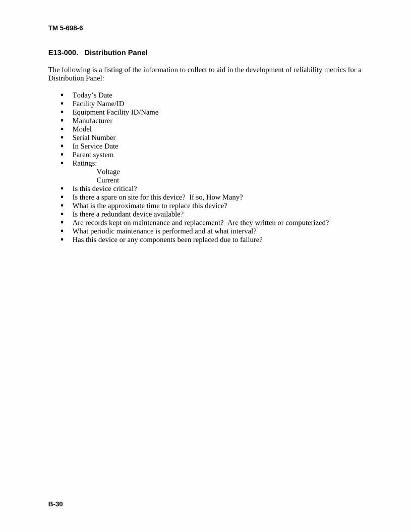
E13-000. Distribution Panel The following is a listing of the information to collect to aid in the development of reliability metrics for a Distribution Panel:
Today’s Date Facility Name/ID Equipment Facility ID/Name Manufacturer Model Serial Number In Service Date Parent system Ratings:
Voltage Current
Is this device critical? Is there a spare on site for this device? If so, How Many? What is the approximate time to replace this device? Is there a redundant device available? Are records kept on maintenance and replacement? Are they written or computerized? What periodic maintenance is performed and at what interval? Has this device or any components been replaced due to failure?
TM 5-698-6
B-31
E14-000. Drive The following is a listing of the information to collect to aid in the development of reliability metrics for a Drive:
Today’s Date Facility Name/ID Equipment Facility ID/Name Manufacturer Model Serial Number In Service Date Parent system Type: adjustable speed or variable frequency Is this device critical? Is there a spare on site for this device? If so, How Many? What is the approximate time to replace this device? Is there a redundant device available? Are records kept on maintenance and replacement? Are they written or computerized? What periodic maintenance is performed and at what interval? Has this device or any components been replaced due to failure?
TM 5-698-6
B-32
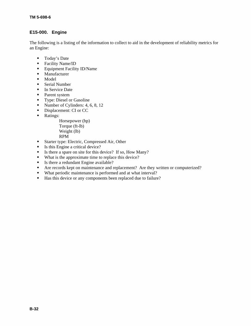
E15-000. Engine The following is a listing of the information to collect to aid in the development of reliability metrics for an Engine:
Today’s Date Facility Name/ID Equipment Facility ID/Name Manufacturer Model Serial Number In Service Date Parent system Type: Diesel or Gasoline Number of Cylinders: 4, 6, 8, 12 Displacement: CI or CC Ratings:
Horsepower (hp) Torque (ft-lb) Weight (lb) RPM Starter type: Electric, Compressed Air, Other Is this Engine a critical device? Is there a spare on site for this device? If so, How Many? What is the approximate time to replace this device? Is there a redundant Engine available? Are records kept on maintenance and replacement? Are they written or computerized? What periodic maintenance is performed and at what interval? Has this device or any components been replaced due to failure?

TM 5-698-6
B-33
E16-000. Filter, Electrical The following is a listing of the information to collect to aid in the development of reliability metrics for an Electrical Filter:
Today’s Date Facility Name/ID Equipment Facility ID/Name Manufacturer Model Serial Number In Service Date Parent system Use: Tempest, HEMP Ratings:
Voltage Current Is this Filter connected to critical equipment? Is there a spare on site for this device? If so, How Many? What is the approximate time to replace this device? Is there a redundant Filter available? Are records kept on maintenance and replacement? Are they written or computerized? What periodic maintenance is performed and at what interval? Has this device or any components been replaced due to failure?
TM 5-698-6
B-34
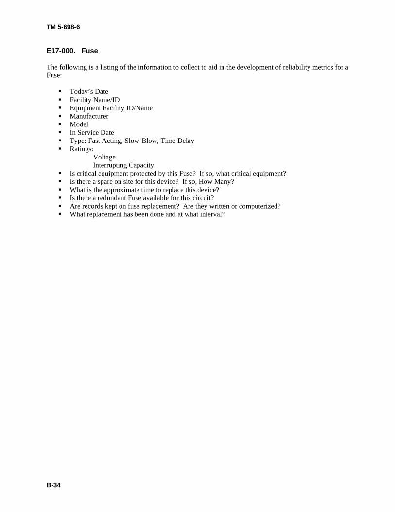
E17-000. Fuse The following is a listing of the information to collect to aid in the development of reliability metrics for a Fuse:
Today’s Date Facility Name/ID Equipment Facility ID/Name Manufacturer Model In Service Date Type: Fast Acting, Slow-Blow, Time Delay Ratings:
Voltage Interrupting Capacity
Is critical equipment protected by this Fuse? If so, what critical equipment? Is there a spare on site for this device? If so, How Many? What is the approximate time to replace this device? Is there a redundant Fuse available for this circuit? Are records kept on fuse replacement? Are they written or computerized? What replacement has been done and at what interval?
TM 5-698-6
B-35
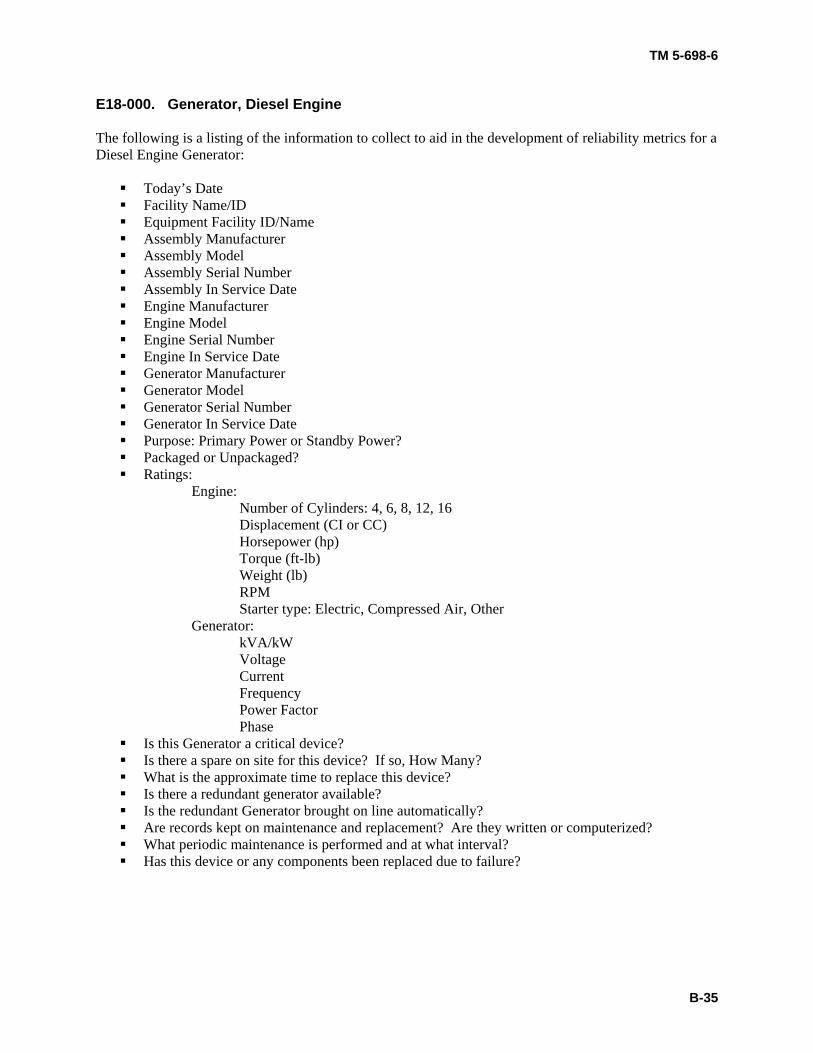
E18-000. Generator, Diesel Engine The following is a listing of the information to collect to aid in the development of reliability metrics for a Diesel Engine Generator:
Today’s Date Facility Name/ID Equipment Facility ID/Name Assembly Manufacturer Assembly Model Assembly Serial Number Assembly In Service Date Engine Manufacturer Engine Model Engine Serial Number Engine In Service Date Generator Manufacturer Generator Model Generator Serial Number Generator In Service Date Purpose: Primary Power or Standby Power? Packaged or Unpackaged? Ratings:
Engine: Number of Cylinders: 4, 6, 8, 12, 16
Displacement (CI or CC) Horsepower (hp) Torque (ft-lb) Weight (lb) RPM Starter type: Electric, Compressed Air, Other Generator:
kVA/kW Voltage Current Frequency Power Factor Phase
Is this Generator a critical device? Is there a spare on site for this device? If so, How Many? What is the approximate time to replace this device? Is there a redundant generator available? Is the redundant Generator brought on line automatically? Are records kept on maintenance and replacement? Are they written or computerized? What periodic maintenance is performed and at what interval? Has this device or any components been replaced due to failure?
TM 5-698-6
B-36
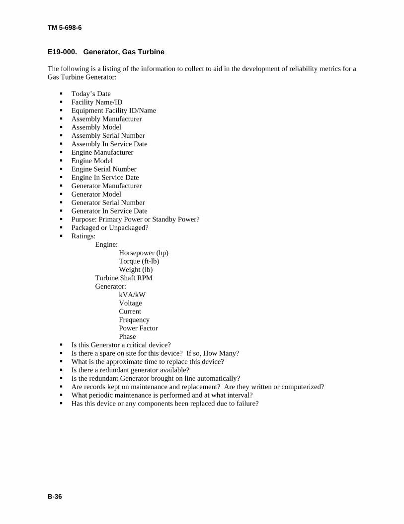
E19-000. Generator, Gas Turbine The following is a listing of the information to collect to aid in the development of reliability metrics for a Gas Turbine Generator:
Today’s Date Facility Name/ID Equipment Facility ID/Name Assembly Manufacturer Assembly Model Assembly Serial Number Assembly In Service Date Engine Manufacturer Engine Model Engine Serial Number Engine In Service Date Generator Manufacturer Generator Model Generator Serial Number Generator In Service Date Purpose: Primary Power or Standby Power? Packaged or Unpackaged? Ratings:
Engine: Horsepower (hp) Torque (ft-lb) Weight (lb) Turbine Shaft RPM Generator:
kVA/kW Voltage Current Frequency Power Factor Phase
Is this Generator a critical device? Is there a spare on site for this device? If so, How Many? What is the approximate time to replace this device? Is there a redundant generator available? Is the redundant Generator brought on line automatically? Are records kept on maintenance and replacement? Are they written or computerized? What periodic maintenance is performed and at what interval? Has this device or any components been replaced due to failure?
TM 5-698-6
B-37
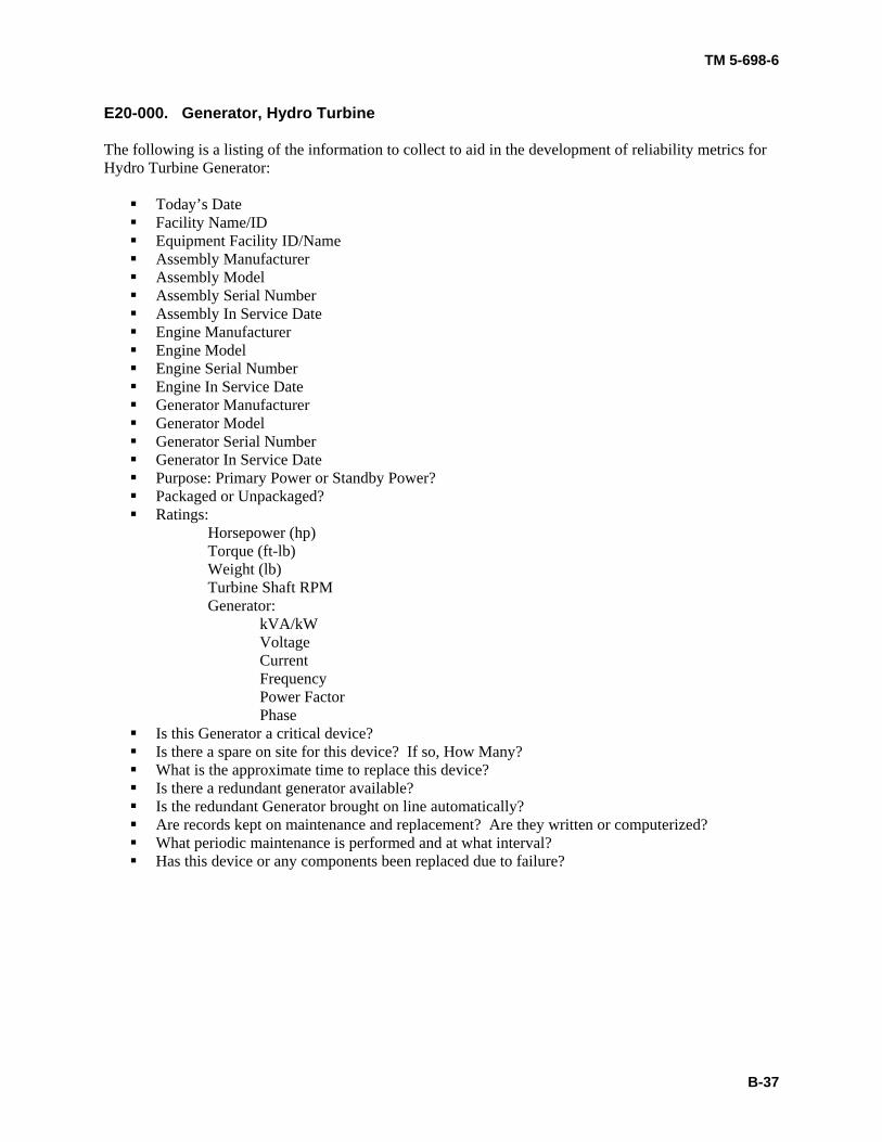
E20-000. Generator, Hydro Turbine The following is a listing of the information to collect to aid in the development of reliability metrics for Hydro Turbine Generator:
Today’s Date Facility Name/ID Equipment Facility ID/Name Assembly Manufacturer Assembly Model Assembly Serial Number Assembly In Service Date Engine Manufacturer Engine Model Engine Serial Number Engine In Service Date Generator Manufacturer Generator Model Generator Serial Number Generator In Service Date Purpose: Primary Power or Standby Power? Packaged or Unpackaged? Ratings:
Horsepower (hp) Torque (ft-lb) Weight (lb) Turbine Shaft RPM Generator:
kVA/kW Voltage Current Frequency Power Factor Phase
Is this Generator a critical device? Is there a spare on site for this device? If so, How Many? What is the approximate time to replace this device? Is there a redundant generator available? Is the redundant Generator brought on line automatically? Are records kept on maintenance and replacement? Are they written or computerized? What periodic maintenance is performed and at what interval? Has this device or any components been replaced due to failure?
TM 5-698-6
B-38
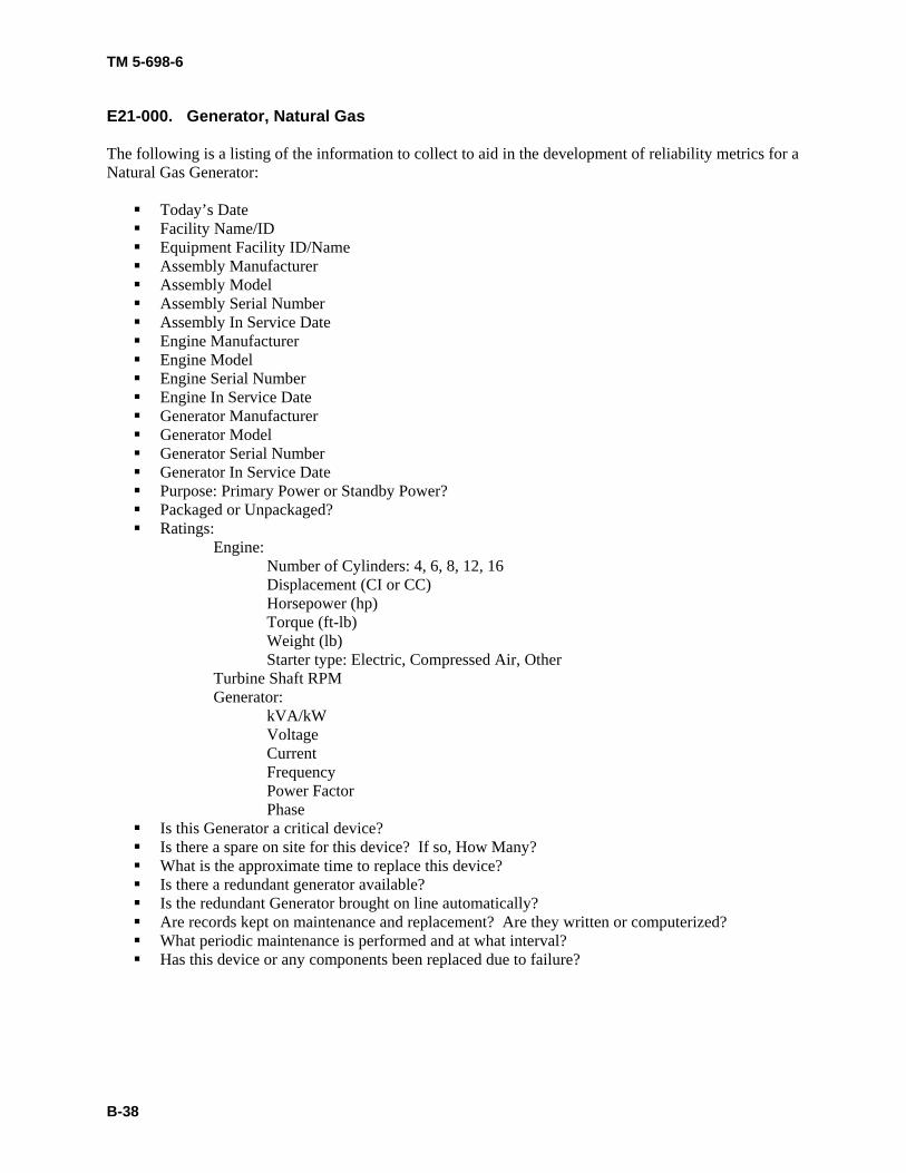
E21-000. Generator, Natural Gas The following is a listing of the information to collect to aid in the development of reliability metrics for a Natural Gas Generator:
Today’s Date Facility Name/ID Equipment Facility ID/Name Assembly Manufacturer Assembly Model Assembly Serial Number Assembly In Service Date Engine Manufacturer Engine Model Engine Serial Number Engine In Service Date Generator Manufacturer Generator Model Generator Serial Number Generator In Service Date Purpose: Primary Power or Standby Power? Packaged or Unpackaged? Ratings:
Engine: Number of Cylinders: 4, 6, 8, 12, 16
Displacement (CI or CC) Horsepower (hp) Torque (ft-lb) Weight (lb) Starter type: Electric, Compressed Air, Other Turbine Shaft RPM Generator:
kVA/kW Voltage Current Frequency Power Factor Phase
Is this Generator a critical device? Is there a spare on site for this device? If so, How Many? What is the approximate time to replace this device? Is there a redundant generator available? Is the redundant Generator brought on line automatically? Are records kept on maintenance and replacement? Are they written or computerized? What periodic maintenance is performed and at what interval? Has this device or any components been replaced due to failure?
TM 5-698-6
B-39
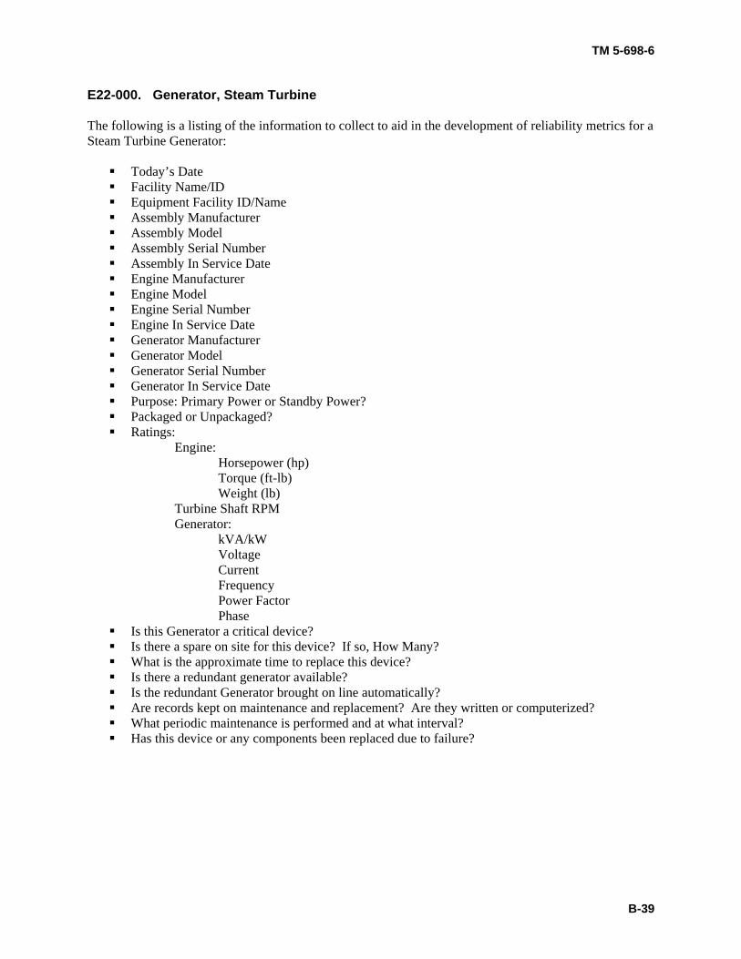
E22-000. Generator, Steam Turbine The following is a listing of the information to collect to aid in the development of reliability metrics for a Steam Turbine Generator:
Today’s Date Facility Name/ID Equipment Facility ID/Name Assembly Manufacturer Assembly Model Assembly Serial Number Assembly In Service Date Engine Manufacturer Engine Model Engine Serial Number Engine In Service Date Generator Manufacturer Generator Model Generator Serial Number Generator In Service Date Purpose: Primary Power or Standby Power? Packaged or Unpackaged? Ratings:
Engine: Horsepower (hp) Torque (ft-lb) Weight (lb) Turbine Shaft RPM Generator:
kVA/kW Voltage Current Frequency Power Factor Phase
Is this Generator a critical device? Is there a spare on site for this device? If so, How Many? What is the approximate time to replace this device? Is there a redundant generator available? Is the redundant Generator brought on line automatically? Are records kept on maintenance and replacement? Are they written or computerized? What periodic maintenance is performed and at what interval? Has this device or any components been replaced due to failure?
TM 5-698-6
B-40
E23-000. Generator, Steam, Heat Recovery The following is a listing of the information to collect to aid in the development of reliability metrics for a Heat Recovery Steam Generator:
Today’s Date Facility Name/ID Equipment Facility ID/Name Assembly Manufacturer Assembly Model Assembly Serial Number Assembly In Service Date Engine Manufacturer Engine Model Engine Serial Number Engine In Service Date Generator Manufacturer Generator Model Generator Serial Number Generator In Service Date Purpose: Primary Power or Standby Power? Ratings:
Horsepower (hp) Torque (ft-lb) Weight (lb) Turbine Shaft RPM Generator:
kVA/kW Voltage Current Frequency Power Factor Phase
Is this Generator a critical device? Is there a spare on site for this device? If so, How Many? What is the approximate time to replace this device? Is there a redundant generator available? Is the redundant Generator brought on line automatically? Are records kept on maintenance and replacement? Are they written or computerized? What periodic maintenance is performed and at what interval? Has this device or any components been replaced due to failure?
TM 5-698-6
B-41
E24-000. Heater The following is a listing of the information to collect to aid in the development of reliability metrics for a Heater:
Today’s Date Facility Name/ID Equipment Facility ID/Name Manufacturer Model Serial Number In Service Date Parent system Type: lube oil, fuel oil, or jacket water Rating:
Voltage Current
Is this device critical? Is there a spare on site for this device? If so, How Many? What is the approximate time to replace this device? Is there a redundant device available? Are records kept on maintenance and replacement? Are they written or computerized? What periodic maintenance is performed and at what interval? Has this device or any components been replaced due to failure?
TM 5-698-6
B-42
E25-000. Inverter, All Types The following is a listing of the information to collect to aid in the development of reliability metrics for an Inverter:
Today’s Date Facility Name/ID Equipment Facility ID/Name Manufacturer Model Serial Number In Service Date Parent system Purpose: Primary Power or Standby Power Ratings:
Input Voltage Input Current Output Voltage Output Current kW Output Frequency Waveform Output Overload Protection Output Power Factor Pulse Rating Response Time Battery Protection Levels
Does this Inverter supply a critical device? Is there a spare on site for this device? If so, How Many? What is the approximate time to replace this device? Is there a redundant Inverter available? Are records kept on maintenance and replacement? Are they written or computerized? What periodic maintenance is performed and at what interval? Has this device or any components been replaced due to failure?
TM 5-698-6
B-43
E26-000. Line Conditioner, All Types The following is a listing of the information to collect to aid in the development of reliability metrics for a Line Conditioner:
Today’s Date Facility Name/ID Equipment Facility ID/Name Manufacturer Model Serial Number In Service Date Parent system Ratings:
Voltage Current Power (kW) kVA
Is this device critical? Is there a spare on site for this device? If so, How Many? What is the approximate time to replace this device? Is there a redundant device available? Are records kept on maintenance and replacement? Are they written or computerized? What periodic maintenance is performed and at what interval? Has this device or any components been replaced due to failure?
TM 5-698-6
B-44
E27-000. Motor Generator Set The following is a listing of the information to collect to aid in the development of reliability metrics for a Motor Generator Set:
Today’s Date Facility Name/ID Equipment Facility ID/Name Manufacturer Model Serial Number In Service Date Parent system Ratings:
Input Voltage Input Current Input Frequency Input Phase Output Voltage Output Current Output Frequency Output Phase
Is this device critical? Is there a spare on site for this device? If so, How Many? What is the approximate time to replace this device? Is there a redundant device available? Are records kept on maintenance and replacement? Are they written or computerized? What periodic maintenance is performed and at what interval? Has this device or any components been replaced due to failure?
TM 5-698-6
B-45
E28-000. Motor Starter The following is a listing of the information to collect to aid in the development of reliability metrics for a Motor Starter:
Today’s Date Facility Name/ID Equipment Facility ID/Name Manufacturer Model Serial Number In Service Date Parent system Ratings:
Voltage Current
Is this device critical? Is there a spare on site for this device? If so, How Many? What is the approximate time to replace this device? Is there a redundant device available? Are records kept on maintenance and replacement? Are they written or computerized? What periodic maintenance is performed and at what interval? Has this device or any components been replaced due to failure?
TM 5-698-6
B-46
E29-000. Motor, Electric The following is a listing of the information to collect to aid in the development of reliability metrics for an Electric Motor:
Today’s Date Facility Name/ID Equipment Facility ID/Name Manufacturer Model Serial Number In Service Date Parent system Ratings:
Horsepower Torque (ft-lbs) Speed (RPM) Voltage Phase Current (Amps) Motor NEMA Frame Is this Motor critical equipment? Is there a spare on site for this device? If so, How Many? What is the approximate time to replace this device? Is there a redundant Motor available? Are records kept on maintenance and replacement? Are they written or computerized? What periodic maintenance is performed and at what interval? Has this device or any components been replaced due to failure?
TM 5-698-6
B-47
E30-000. Oil Cooler The following is a listing of the information to collect to aid in the development of reliability metrics for an Oil Cooler:
Today’s Date Facility Name/ID Equipment Facility ID/Name Manufacturer Model Serial Number In Service Date Parent system Is this device critical? Is there a spare on site for this device? If so, How Many? What is the approximate time to replace this device? Is there a redundant device available? Are records kept on maintenance and replacement? Are they written or computerized? What periodic maintenance is performed and at what interval? Has this device or any components been replaced due to failure?
TM 5-698-6
B-48
E31-000. Recloser (Interrupter) The following is a listing of the information to collect to aid in the development of reliability metrics for a Recloser (Interrupter):
Today’s Date Facility Name/ID Equipment Facility ID/Name Manufacturer Model Serial Number In Service Date Parent system Type: Electronic or Hydraulic Ratings:
Voltage Current Number of Operations before Lockout
Is this device critical? Is there a spare on site for this device? If so, How Many? What is the approximate time to replace this device? Is there a redundant device available? Are records kept on maintenance and replacement? Are they written or computerized? What periodic maintenance is performed and at what interval? Has this device or any components been replaced due to failure?
TM 5-698-6
B-49
E32-000. Rectifier, All Types The following is a listing of the information to collect to aid in the development of reliability metrics for a Rectifier:
Today’s Date Facility Name/ID Equipment Facility ID/Name Manufacturer Model In Service Date Parent system Ratings:
Input Voltage Input Current Output Voltage Output Current
Peak voltage Average forward current Peak surge current Peak forward current Temperature range
Does this Rectifier supply a critical device? Is there a spare on site for this device? If so, How Many? What is the approximate time to replace this device? Is there a redundant Rectifier available? Is the redundant rectifier automatically switched in line? Are records kept on maintenance and replacement? Are they written or computerized? What periodic maintenance is performed and at what interval? Has this device or any components been replaced due to failure?
TM 5-698-6
B-50
E33-000. Relay The following is a listing of the information to collect to aid in the development of reliability metrics for a Relay:
Today’s Date Facility Name/ID Equipment Facility ID/Name Manufacturer Model In Service Date Parent system Class: General Purpose, Latching, Impulse, Stepping
Sequence or Differential Type: Armature, Hybrid, Solid State, Time Delay, Differential Voltage, Drawout, Overcurrent Contact type: Normally Open, Normally Closed
Complex: Number of Poles Ratings:
Contacts: Voltage, Current Coil: Voltage, Resistance Frequency (Hz)
Use: Low Level (low current switching, milliamp)
Intermediate Level (up to 10 Amps) Protective Relay
Special Purpose Does this Relay control a critical device? If so what? Is there a spare on site for this device? If so, How Many? What is the approximate time to replace this device? Is there a redundant Relay available? Are records kept on maintenance and replacement? Are they written or computerized? What periodic maintenance is performed and at what interval? Has this device or any components been replaced due to failure?
TM 5-698-6
B-51
E34-000. Switch The following is a listing of the information to collect to aid in the development of reliability metrics for a Switch:
Today’s Date Facility Name/ID Equipment Facility ID/Name Manufacturer Model Serial Number In Service Date Parent system Type: AC, DC, Automatic Transfer, Manual Transfer, Disconnect – Enclosed, Disconnect –
fused, On/Off Breaker Type (non-knife), Float, Oil Filled, Pressure, Vibration, Static, IGBT Technology
Ratings: Voltage Current
Is this device critical? Is there a spare on site for this device? If so, How Many? What is the approximate time to replace this device? Is there a redundant device available? Are records kept on maintenance and replacement? Are they written or computerized? What periodic maintenance is performed and at what interval? Has this device or any components been replaced due to failure?
TM 5-698-6
B-52
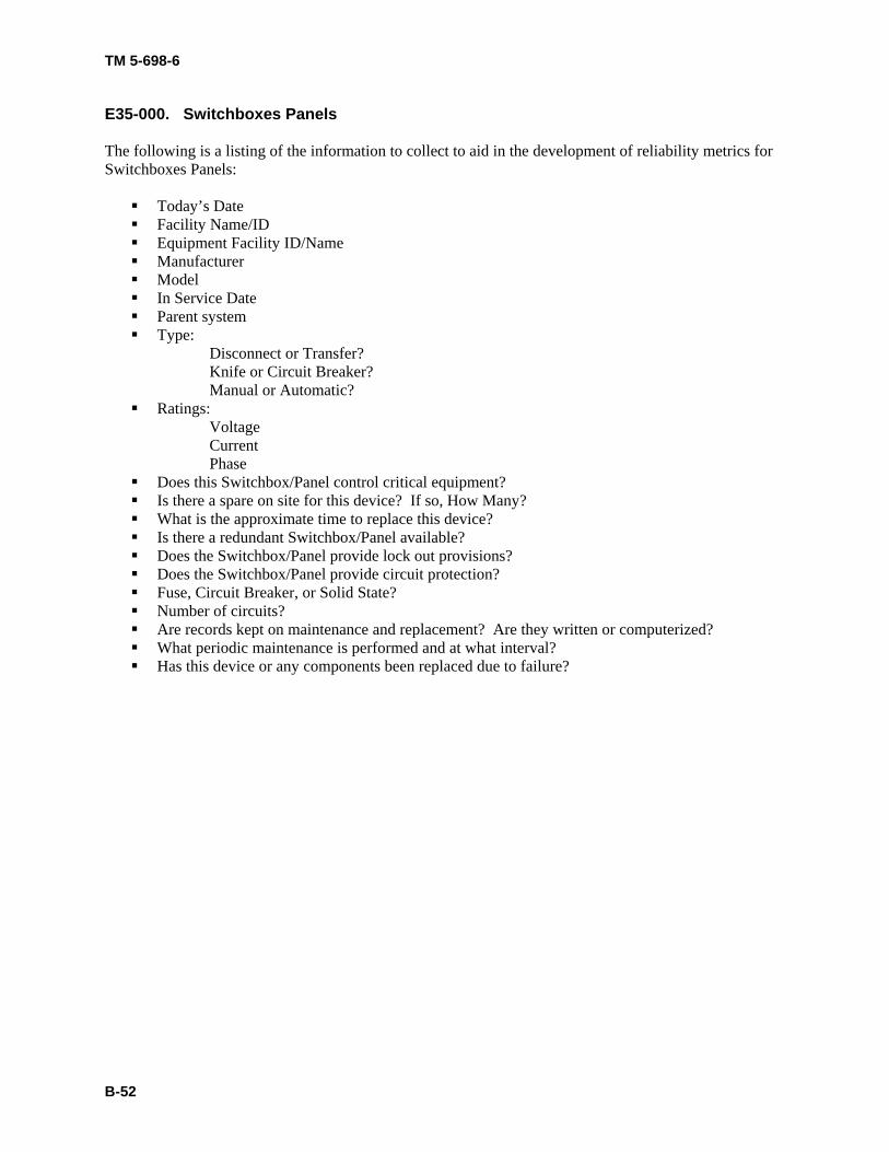
E35-000. Switchboxes Panels The following is a listing of the information to collect to aid in the development of reliability metrics for Switchboxes Panels:
Today’s Date Facility Name/ID Equipment Facility ID/Name Manufacturer Model In Service Date Parent system Type:
Disconnect or Transfer? Knife or Circuit Breaker? Manual or Automatic?
Ratings: Voltage Current Phase
Does this Switchbox/Panel control critical equipment? Is there a spare on site for this device? If so, How Many? What is the approximate time to replace this device? Is there a redundant Switchbox/Panel available? Does the Switchbox/Panel provide lock out provisions? Does the Switchbox/Panel provide circuit protection? Fuse, Circuit Breaker, or Solid State? Number of circuits? Are records kept on maintenance and replacement? Are they written or computerized? What periodic maintenance is performed and at what interval? Has this device or any components been replaced due to failure?

TM 5-698-6
B-53
E36-000. Switchgear The following is a listing of the information to collect to aid in the development of reliability metrics for Switchgear:
Today’s Date Facility Name/ID Equipment Facility ID/Name Manufacturer Model Serial Number In Service Date Parent system Type: Bare bus or insulated bus Number of Cabinets Ratings:
Voltage Current
Is this device critical? Is there a spare on site for this device? If so, How Many? What is the approximate time to replace this device? Is there a redundant device available? Are records kept on maintenance and replacement? Are they written or computerized? What periodic maintenance is performed and at what interval? Has this device or any components been replaced due to failure?
TM 5-698-6
B-54
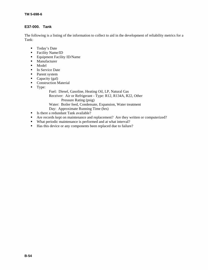
E37-000. Tank The following is a listing of the information to collect to aid in the development of reliability metrics for a Tank:
Today’s Date Facility Name/ID Equipment Facility ID/Name Manufacturer Model In Service Date Parent system Capacity (gal) Construction Material Type:
Fuel: Diesel, Gasoline, Heating Oil, LP, Natural Gas Receiver: Air or Refrigerant - Type: R12, R134A, R22, Other Pressure Rating (psig) Water: Boiler feed, Condensate, Expansion, Water treatment Day: Approximate Running Time (hrs)
Is there a redundant Tank available? Are records kept on maintenance and replacement? Are they written or computerized? What periodic maintenance is performed and at what interval? Has this device or any components been replaced due to failure?
TM 5-698-6
B-55
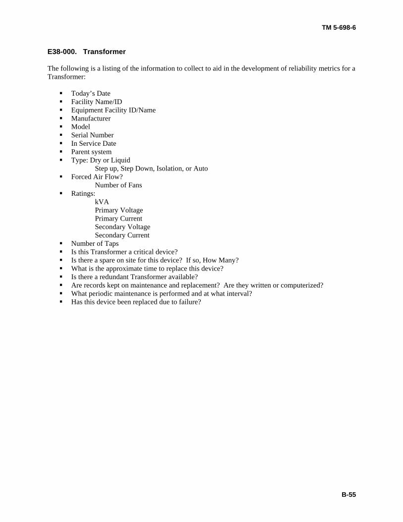
E38-000. Transformer The following is a listing of the information to collect to aid in the development of reliability metrics for a Transformer:
Today’s Date Facility Name/ID Equipment Facility ID/Name Manufacturer Model Serial Number In Service Date Parent system Type: Dry or Liquid
Step up, Step Down, Isolation, or Auto Forced Air Flow?
Number of Fans Ratings:
kVA Primary Voltage Primary Current Secondary Voltage Secondary Current
Number of Taps Is this Transformer a critical device? Is there a spare on site for this device? If so, How Many? What is the approximate time to replace this device? Is there a redundant Transformer available? Are records kept on maintenance and replacement? Are they written or computerized? What periodic maintenance is performed and at what interval? Has this device been replaced due to failure?
TM 5-698-6
B-56
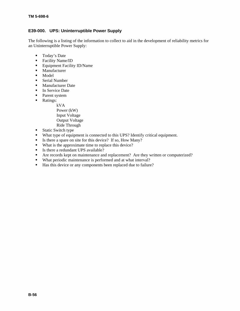
E39-000. UPS: Uninterruptible Power Supply The following is a listing of the information to collect to aid in the development of reliability metrics for an Uninterruptible Power Supply:
Today’s Date Facility Name/ID Equipment Facility ID/Name Manufacturer Model Serial Number Manufacturer Date In Service Date Parent system Ratings:
kVA Power (kW) Input Voltage Output Voltage Ride Through
Static Switch type What type of equipment is connected to this UPS? Identify critical equipment. Is there a spare on site for this device? If so, How Many? What is the approximate time to replace this device? Is there a redundant UPS available? Are records kept on maintenance and replacement? Are they written or computerized? What periodic maintenance is performed and at what interval? Has this device or any components been replaced due to failure?
TM 5-698-6
B-57
E40-000. Voltage Regulator The following is a listing of the information to collect to aid in the development of reliability metrics for a Voltage Regulator:
Today’s Date Facility Name/ID Equipment Facility ID/Name Manufacturer Model In Service Date Parent system Ratings:
Input Voltage Input Current Output Voltage Output Current
Does this Voltage Regulator control critical equipment? Is there a spare on site for this device? If so, How Many? What is the approximate time to replace this device? Is there a redundant Voltage Regulator available? Are records kept on maintenance and replacement? Are they written or computerized? What periodic maintenance is performed and at what interval? Has this device or any components been replaced due to failure?
TM 5-698-6
B-58
CATEGORY H: HVAC Equipment H1-000. Accumulator The following is a listing of the information to collect to aid in the development of reliability metrics for a Accumulator:
Today’s Date Facility Name/ID Equipment Facility ID/Name Manufacturer Model Serial Number In Service Date Parent system Capacity (gal or liter) Is the Accumulator pressurized? If so, what is the maximum pressure (psi)? Is this accumulator critical equipment? Is there a spare on site for this device? If so, How Many? What is the approximate time to replace this device? Is there a redundant Accumulator available? Are records kept on maintenance and replacement? Are they written or computerized? What periodic maintenance is performed and at what interval? Has this device or any components been replaced due to failure?
TM 5-698-6
B-59
H2-000. Air Compressor The following is a listing of the information to collect to aid in the development of reliability metrics for an Air Compressor:
Today’s Date Facility Name/ID Equipment Facility ID/Name Manufacturer Model Serial Number In Service Date Parent system Type: Electric or Fuel Ratings:
Pressure (psig) Is this device critical? Is there a spare on site for this device? If so, How Many? What is the approximate time to replace this device? Is there a redundant device available? Are records kept on maintenance and replacement? Are they written or computerized? What periodic maintenance is performed and at what interval? Has this device or any components been replaced due to failure?
TM 5-698-6
B-60
H3-000. Air Conditioner The following is a listing of the information to collect to aid in the development of reliability metrics for an Air Conditioner:
Today’s Date Facility Name/ID Equipment Facility ID/Name Manufacturer Model Serial Number In Service Date Parent system Compressor Type: (Reciprocating or Screw) Refrigerant Type: R-12, R-134A, R-22, Other Ratings:
Cooling Capacity (BTU/hr) Voltage
Is this device critical? Is there a spare on site for this device? If so, How Many? What is the approximate time to replace this device? Is there a redundant device available? Are records kept on maintenance and replacement? Are they written or computerized? What periodic maintenance is performed and at what interval? Has this device or any components been replaced due to failure?
TM 5-698-6
B-61
H4-000. Air Dryer, All Types The following is a listing of the information to collect to aid in the development of reliability metrics for an Air Dryer:
Today’s Date Facility Name/ID Equipment Facility ID/Name Manufacturer Model Serial Number In Service Date Parent System Location Types:
Refrigerant Desiccant Membrane In-line
Maximum Pressure Pipe Size Is this Air Dryer critical equipment? Is there a spare on site for this device? If so, How Many? What is the approximate time to replace this device? Is there a redundant Air Dryer available? Are records kept on maintenance and replacement? Are they written or computerized? What periodic maintenance is performed and at what interval? Has this device or any components been replaced due to failure?
TM 5-698-6
B-62
H5-000. Air Handling Unit The following is a listing of the information to collect to aid in the development of reliability metrics for a Air Handling Unit:
Today’s Date Facility Name/ID Equipment Facility ID/Name Manufacturer Model Serial Number In Service Date Nominal cooling capacity (tons) Nominal heating capacity (BTU) Nominal air volume (CFM) Supply Power:
Voltage Phase Frequency Humidity Control: None, Pan, Spray Is there an air filter? Evaporator Type Coil:
Face Area Rows/fins Operating charge (kg) Chilled water or Refrigerant: R12, R134A, R22 Fan:
Diameter (in) Air volume (CFM) Motor HP Motor RPM Is this Air Handling Unit critical equipment? Is there a spare on site for this device? If so, How Many? What is the approximate time to replace this device? Is there a redundant Air Handling Unit available? Are records kept on maintenance and replacement? Are they written or computerized? What periodic maintenance is performed and at what interval? Has this device or any components been replaced due to failure?
TM 5-698-6
B-63
H6-000. Air Separator, All Types The following is a listing of the information to collect to aid in the development of reliability metrics for an Air Separator:
Today’s Date Facility Name/ID Equipment Facility ID/Name Manufacturer Model Serial Number In Service Date Parent system Types:
Screener - Drum / Rotary Sifter Screener - Rectangular Deck Screener - Round Deck Air Classifier / Cyclone Magnetic Separator Trommel / Sorter Water / Hydraulic Classifier
Is this device critical? Is there a spare on site for this device? If so, How Many? What is the approximate time to replace this device? Is there a redundant device available? Are records kept on maintenance and replacement? Are they written or computerized? What periodic maintenance is performed and at what interval? Has this device or any components been replaced due to failure?
TM 5-698-6
B-64
H7-000. Blower The following is a listing of the information to collect to aid in the development of reliability metrics for a Blower:
Today’s Date Facility Name/ID Equipment Facility ID/Name Manufacturer Model Serial Number In Service Date Parent system Ratings:
Capacity (CFM) Maximum RPM Voltage Current
Is this Blower critical equipment? Is there a spare on site for this device? If so, How Many? What is the approximate time to replace this device? Is there a redundant Blower available? Are records kept on maintenance and replacement? Are they written or computerized? What periodic maintenance is performed and at what interval? Has this device or any components been replaced due to failure?
TM 5-698-6
B-65
H8-000. Boiler The following is a listing of the information to collect to aid in the development of reliability metrics for a Boiler:
Today’s Date Facility Name/ID Equipment Facility ID/Name Manufacturer Model Serial Number In Service Date Type: Hot Water, Low Pressure Steam, or High Pressure Steam Fuel: Natural Gas, LP Gas, Oil, Diesel, Other Ratings:
Heating Size (BTU) Capacity (gal) Pressure (psi) Efficiency (%)
Pilot light or Electronic Igniter Does the system contain zones? If so, how many? Does the system contain a pump? If so, how many? Zone valve:
Manufacturer Model Pump:
Manufacturer Model Expansion Tank:
Manufacturer Model Does the system contain a pressure safety valve? Is this a critical HVAC system? Is there a spare on site for this device? If so, How Many? What is the approximate time to replace this device? Is there a redundant Boiler available? Are records kept on maintenance and replacement? Are they written or computerized? What periodic maintenance is performed and at what interval? Has this device or any components been replaced due to failure?
TM 5-698-6
B-66
H9-000. Cabinet Heater/Radiator The following is a listing of the information to collect to aid in the development of reliability metrics for a Cabinet Heater/Radiator:
Today’s Date Facility Name/ID Equipment Facility ID/Name Manufacturer Model Serial Number In Service Date Parent system Type: Electric, Steam, or Hot Water Electrical:
Supply Voltage Current Phase Frequency Watts Steam or Hot Water:
Connection sizes (in) Pressures (psi) Heat Capacity (BTU) Is this a critical HVAC system? Is there a spare on site for this device? If so, How Many? What is the approximate time to replace this device? Is there a redundant Cabinet Heater available? Are records kept on maintenance and replacement? Are they written or computerized? What periodic maintenance is performed and at what interval? Has this device or any components been replaced due to failure?
TM 5-698-6
B-67
H10-000. Chiller The following is a listing of the information to collect to aid in the development of reliability metrics for a Chiller:
Today’s Date Facility Name/ID Equipment Facility ID/Name Manufacturer Model Serial Number In Service Date Capacity (Tons, kW, Kcal/hr) Number of compressors Compressor motor:
Manufacturer Model Horsepower Voltage Motor frame number
Water flow rate (gpm or Lps) Refrigerant Type: R12, R134a, R22, Other Refrigerant charge (kg) Type: Absorption, Centrifugal, Reciprocating, Rotary, Screw Is this a critical HVAC system? Is there a spare on site for this device? If so, How Many? What is the approximate time to replace this device? Is there a redundant Chiller available? Are records kept on maintenance and replacement? Are they written or computerized? What periodic maintenance is performed and at what interval? Has this device or any components been replaced due to failure?
TM 5-698-6
B-68
H11-000. Compressor, Refrigerant The following is a listing of the information to collect to aid in the development of reliability metrics for a Refrigerant Compressor:
Today’s Date Facility Name/ID Equipment Facility ID/Name Manufacturer Model Serial Number In Service Date Parent system Type: Electric, Gasoline, or Diesel
Reciprocating, centrifugal, screw Ratings:
Motor/Engine Horsepower Motor Voltage Motor Current (Amps) Motor Phase Motor Speed (RPM) CFM output Maximum Rated Pressure (psi) Receiver Capacity (gal) Refrigerant volume (cc, L, pt, or qt) Refrigerant Type: R12, R134a, R22, Other Is this Compressor critical equipment? Is there a spare on site for this device? If so, How Many? What is the approximate time to replace this device? Is there a redundant Compressor available? Are records kept on maintenance and replacement? Are they written or computerized? What periodic maintenance is performed and at what interval? Has this device or any components been replaced due to failure?
TM 5-698-6
B-69
H12-000. Condenser The following is a listing of the information to collect to aid in the development of reliability metrics for a Condenser:
Today’s Date Facility Name/ID Equipment Facility ID/Name Manufacturer Model Serial Number In Service Date Parent system Type: Double Tube, Propeller type fans with coils, or Shell and Tube (refrigerant/water or wa-
ter/water) Ratings:
Capacity (kW) Fan Diameter (in) Fan Motor Horsepower Fan Motor Speed (RPM) Fan Motor Voltage Fan Motor Phase Fan Motor Current (Amps) Flow Rate (CFM) Refrigerant Volume (cc, L, pt, or qt) Refrigerant Type: R12, R134a, R22, Other Is this Condenser critical equipment? Is there a spare on site for this device? If so, How Many? What is the approximate time to replace this device? Is there a redundant Condenser available? Are records kept on maintenance and replacement? Are they written or computerized? What periodic maintenance is performed and at what interval? Has this device or any components been replaced due to failure?
TM 5-698-6
B-70
H13-000. Convector The following is a listing of the information to collect to aid in the development of reliability metrics for a Convector:
Today’s Date Facility Name/ID Equipment Facility ID/Name Manufacturer Model Serial Number In Service Date Parent system Type: Electric, Steam, or Hot Water Ratings:
Heat output (BTU or kW) Voltage Phase Current (Amps) Pressure, maximum (psi) Is this Convector critical equipment? Is there a spare on site for this device? If so, How Many? What is the approximate time to replace this device? Is there a redundant Convector available? Are records kept on maintenance and replacement? Are they written or computerized? What periodic maintenance is performed and at what interval? Has this device been replaced due to failure?
TM 5-698-6
B-71
H14-000. Cooling Tower The following is a listing of the information to collect to aid in the development of reliability metrics for a Cooling Tower:
Today’s Date Facility Name/ID Equipment Facility ID/Name Manufacturer Model Serial Number In Service Date Type: Atmospheric or Evaporative Number of Fans Number of Cells Ratings:
Flow Rate (gpm) Capacity
Are records kept on maintenance and replacement? Are they written or computerized? What periodic maintenance is performed and at what interval? Has this device or any components been replaced due to failure?
TM 5-698-6
B-72
H15-000. Damper Assembly The following is a listing of the information to collect to aid in the development of reliability metrics for a Damper Assembly:
Today’s Date Facility Name/ID Equipment Facility ID/Name Manufacturer Model Serial Number In Service Date Parent system Type: Electric or Pneumatic Ratings:
Temperature Range (oC or oF) Duct Size (ft2) Voltage Phase Current Motor NEMA Frame Pressure, Operating (in Hg) Pressure, Maximum (in Hg) Operational Load %kVA (If Known) Is this Damper critical equipment? Is there a spare on site for this device? If so, How Many? What is the approximate time to replace this device? Is there a redundant Damper available? Are records kept on maintenance and replacement? Are they written or computerized? What periodic maintenance is performed and at what interval? Has this device been replaced due to failure?
TM 5-698-6
B-73
H16-000. Dehumidifier The following is a listing of the information to collect to aid in the development of reliability metrics for a Dehumidifier:
Today’s Date Facility Name/ID Equipment Facility ID/Name Manufacturer Model Serial Number In Service Date Parent system Ratings:
Dehumidification rate Capacity
Is this device critical? Is there a spare on site for this device? If so, How Many? What is the approximate time to replace this device? Is there a redundant device available? Are records kept on maintenance and replacement? Are they written or computerized? What periodic maintenance is performed and at what interval? Has this device or any components been replaced due to failure?
TM 5-698-6
B-74
H17-000. Direct Fired Furnace The following is a listing of the information to collect to aid in the development of reliability metrics for a Direct Fired Furnace:
Today’s Date Facility Name/ID Equipment Facility ID/Name Manufacturer Model Serial Number In Service Date Fuel: Natural Gas, LP Gas, Oil, Other Ratings:
Heat Output (BTU/hr) Voltage Phase Current Motor NEMA Frame Is this Direct Fired Furnace critical equipment? Is there a spare on site for this device? If so, How Many? What is the approximate time to replace this device? Is there a redundant Direct Fired Furnace available? Are records kept on maintenance and replacement? Are they written or computerized? What periodic maintenance is performed and at what interval? Has this device or any components been replaced due to failure?
TM 5-698-6
B-75
H18-000. Evaporator The following is a listing of the information to collect to aid in the development of reliability metrics for a Evaporator:
Today’s Date Facility Name/ID Equipment Facility ID/Name Manufacturer Model Serial Number In Service Date Parent system Type: Air or Liquid Design: Coil or Shell and Tube Ratings:
Heat Transfer Rate (BTU/hr) Voltage Phase Current (Amps) Motor NEMA Frame Liquid type Liquid Capacity Refrigerant type: R12, R134a, R22, water, Other Is this Evaporator unit critical equipment? Is there a spare on site for this device? If so, How Many? What is the approximate time to replace this device? Is there a redundant Evaporator available? Are records kept on maintenance and replacement? Are they written or computerized? What periodic maintenance is performed and at what interval? Has this device or any components been replaced due to failure?
TM 5-698-6
B-76
H19-000. Fan The following is a listing of the information to collect to aid in the development of reliability metrics for a Fan:
Today’s Date Facility Name/ID Equipment Facility ID/Name Manufacturer Model Serial Number In Service Date Parent system Type: Centrifugal, Propeller/disc, Tube-axial, or Vane-axial Ratings:
Size (in) Output (CFM) Number of Blades Motor Horsepower Motor Speed Voltage Phase Current Motor NEMA Frame Is this Fan critical equipment? Is there a spare on site for this device? If so, How Many? What is the approximate time to replace this device? Is there a redundant Fan available? Are records kept on maintenance and replacement? Are they written or computerized? What periodic maintenance is performed and at what interval? Has this device or any components been replaced due to failure?
TM 5-698-6
B-77
H20-000. Filter, Mechanical The following is a listing of the information to collect to aid in the development of reliability metrics for a Mechanical Filter:
Today’s Date Facility Name/ID Equipment Facility ID/Name Manufacturer Model Serial Number In Service Date Parent system Use: Air, Lube oil, Fuel oil, or Gasoline Ratings:
Inlet Size (ID ,in2 or ft2) Outlet Size (ID ,in2 or ft2) Inlet Pressure, Max (psi) Outlet Pressure, Max (psi) Flow Rate (gpm or CFM) Temperature, Maximum (oC or oF) Filter Element Is this Filter connected to critical equipment? Is there a spare on site for this device? If so, How Many? What is the approximate time to replace this device? Is there a redundant Filter available? Are records kept on maintenance and replacement? Are they written or computerized? What periodic maintenance is performed and at what interval? Has this device or any components been replaced due to failure?
TM 5-698-6
B-78
H21-000. Heat Exchanger The following is a listing of the information to collect to aid in the development of reliability metrics for a Heat Exchanger:
Today’s Date Facility Name/ID Equipment Facility ID/Name Manufacturer Model Serial Number In Service Date Parent System Type: Steam, Water to Water, Lube Oil, Radiator (Small Tube) Ratings:
Heat Transfer Rate (BTU/hr) Efficiency (%) Is this Heat Exchanger critical equipment? Is there a spare on site for this device? If so, How Many? What is the approximate time to replace this device? Is there a redundant Heat Exchanger available? Are records kept on maintenance and replacement? Are they written or computerized? What periodic maintenance is performed and at what interval? Has this device or any components been replaced due to failure?
TM 5-698-6
B-79
H22-000. Heat Pump The following is a listing of the information to collect to aid in the development of reliability metrics for a Heat Pump:
Today’s Date Facility Name/ID Equipment Facility ID/Name Manufacturer Model Serial Number In Service Date Parent system Ratings:
Capacity (Tons) Output (BTU/hr) Voltage Current
Compressor Type: Reciprocating or screw Refrigerant Type: R12, R-134a, R-22, Other Is this device critical? Is there a spare on site for this device? If so, How Many? What is the approximate time to replace this device? Is there a redundant device available? Are records kept on maintenance and replacement? Are they written or computerized? What periodic maintenance is performed and at what interval? Has this device or any components been replaced due to failure?
TM 5-698-6
B-80
H23-000. Humidifier The following is a listing of the information to collect to aid in the development of reliability metrics for a Humidifier:
Today’s Date Facility Name/ID Equipment Facility ID/Name Manufacturer Model Serial Number In Service Date Parent system Capacity Type: Liquid to Steam or Steam to Steam Is this device critical? Is there a spare on site for this device? If so, How Many? What is the approximate time to replace this device? Is there a redundant device available? Are records kept on maintenance and replacement? Are they written or computerized? What periodic maintenance is performed and at what interval? Has this device or any components been replaced due to failure?
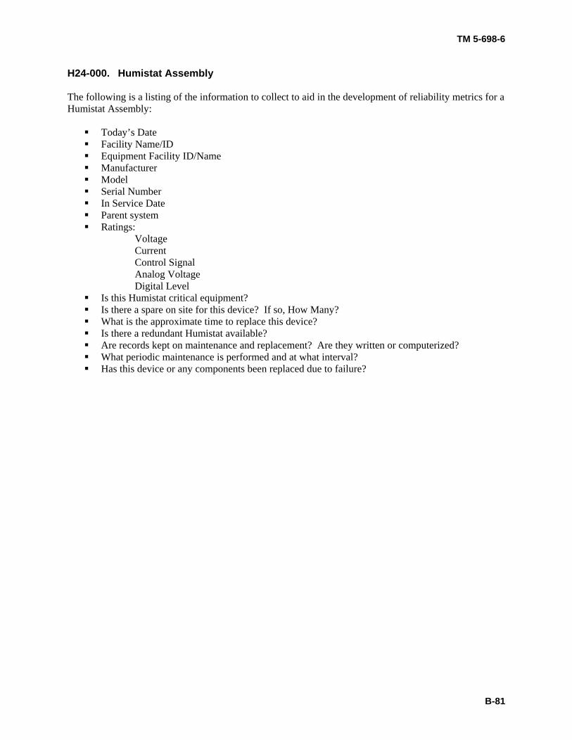
TM 5-698-6
B-81
H24-000. Humistat Assembly The following is a listing of the information to collect to aid in the development of reliability metrics for a Humistat Assembly:
Today’s Date Facility Name/ID Equipment Facility ID/Name Manufacturer Model Serial Number In Service Date Parent system Ratings:
Voltage Current Control Signal Analog Voltage Digital Level Is this Humistat critical equipment? Is there a spare on site for this device? If so, How Many? What is the approximate time to replace this device? Is there a redundant Humistat available? Are records kept on maintenance and replacement? Are they written or computerized? What periodic maintenance is performed and at what interval? Has this device or any components been replaced due to failure?
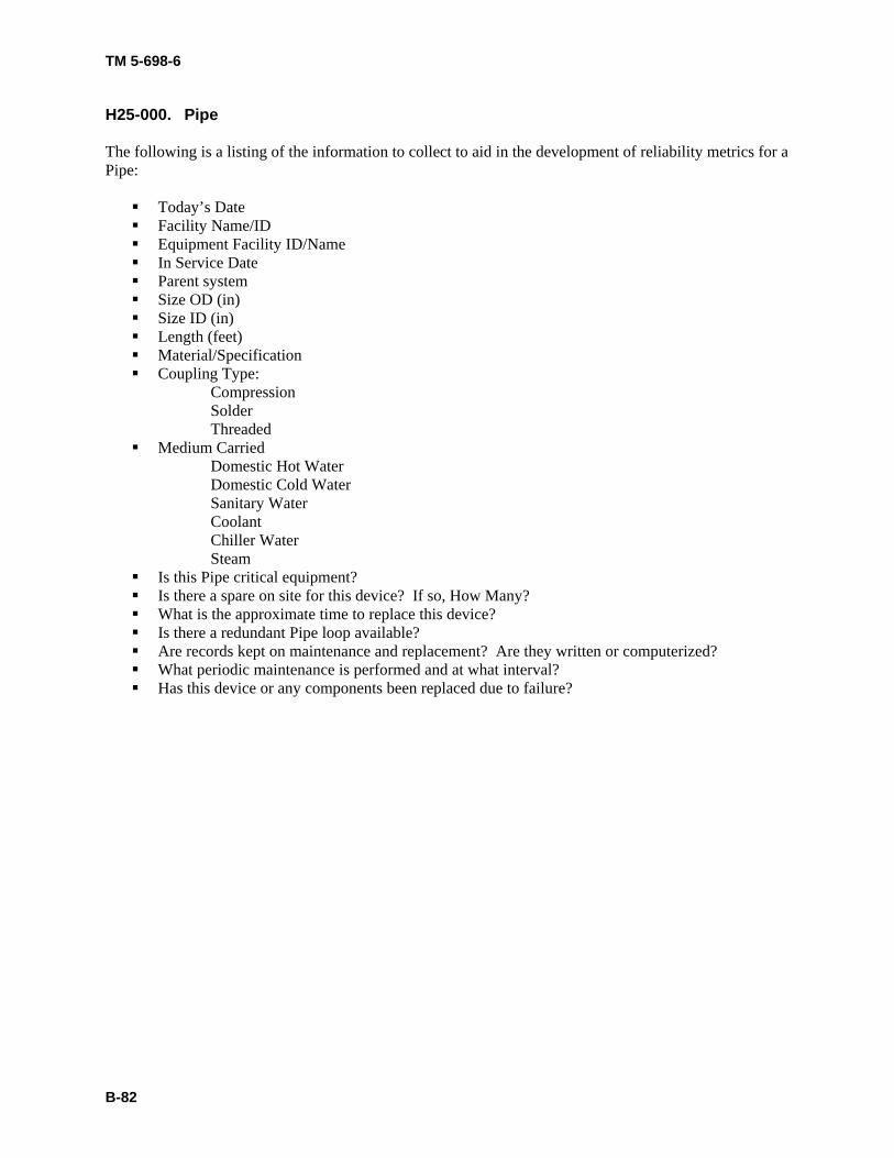
TM 5-698-6
B-82
H25-000. Pipe The following is a listing of the information to collect to aid in the development of reliability metrics for a Pipe:
Today’s Date Facility Name/ID Equipment Facility ID/Name In Service Date Parent system Size OD (in) Size ID (in) Length (feet) Material/Specification Coupling Type:
Compression Solder Threaded
Medium Carried Domestic Hot Water Domestic Cold Water Sanitary Water Coolant Chiller Water Steam
Is this Pipe critical equipment? Is there a spare on site for this device? If so, How Many? What is the approximate time to replace this device? Is there a redundant Pipe loop available? Are records kept on maintenance and replacement? Are they written or computerized? What periodic maintenance is performed and at what interval? Has this device or any components been replaced due to failure?
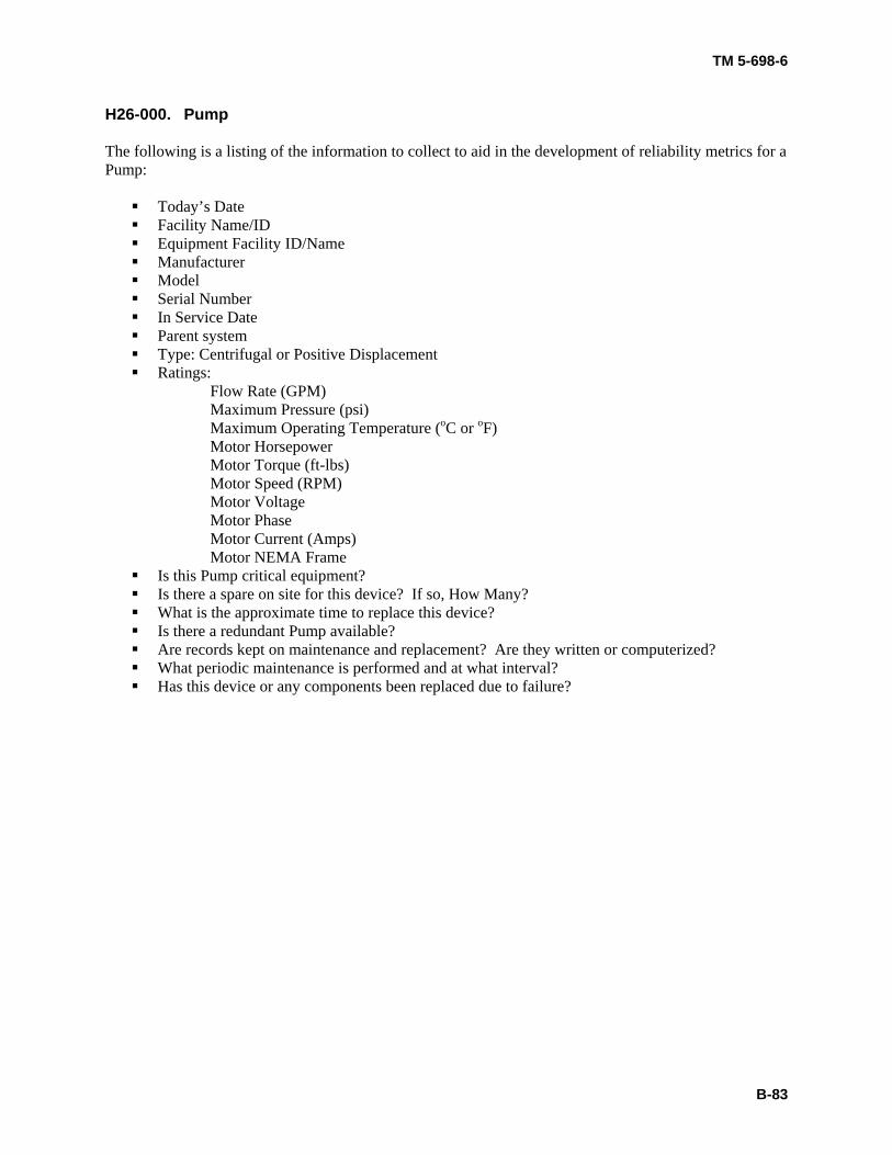
TM 5-698-6
B-83
H26-000. Pump The following is a listing of the information to collect to aid in the development of reliability metrics for a Pump:
Today’s Date Facility Name/ID Equipment Facility ID/Name Manufacturer Model Serial Number In Service Date Parent system Type: Centrifugal or Positive Displacement Ratings:
Flow Rate (GPM) Maximum Pressure (psi) Maximum Operating Temperature (oC or oF) Motor Horsepower Motor Torque (ft-lbs) Motor Speed (RPM) Motor Voltage Motor Phase Motor Current (Amps) Motor NEMA Frame Is this Pump critical equipment? Is there a spare on site for this device? If so, How Many? What is the approximate time to replace this device? Is there a redundant Pump available? Are records kept on maintenance and replacement? Are they written or computerized? What periodic maintenance is performed and at what interval? Has this device or any components been replaced due to failure?
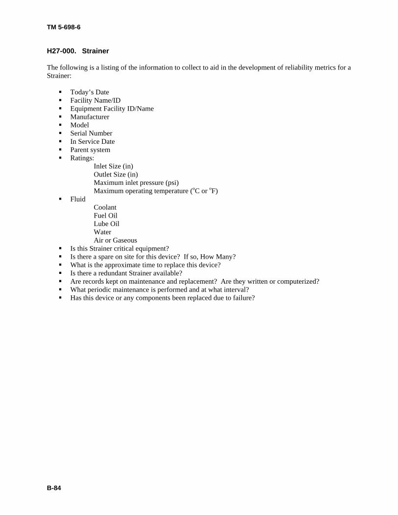
TM 5-698-6
B-84
H27-000. Strainer The following is a listing of the information to collect to aid in the development of reliability metrics for a Strainer:
Today’s Date Facility Name/ID Equipment Facility ID/Name Manufacturer Model Serial Number In Service Date Parent system Ratings:
Inlet Size (in) Outlet Size (in) Maximum inlet pressure (psi) Maximum operating temperature (oC or oF) Fluid
Coolant Fuel Oil Lube Oil Water Air or Gaseous
Is this Strainer critical equipment? Is there a spare on site for this device? If so, How Many? What is the approximate time to replace this device? Is there a redundant Strainer available? Are records kept on maintenance and replacement? Are they written or computerized? What periodic maintenance is performed and at what interval? Has this device or any components been replaced due to failure?
TM 5-698-6
B-85
H28-000. Valve The following is a listing of the information to collect to aid in the development of reliability metrics for a Valve:
Today’s Date Facility Name/ID Equipment Facility ID/Name Manufacturer Model Serial Number In Service Date Parent system Type: Diverting, Mixing Ball, Butterfly Check, Control, Expansion, Gate, Globe, Plug, Relief, or
Suction? Position: Normally Open or Normally Closed Control: Manual, Electrical, Pneumatic Construction Material Ratings:
Voltage Current Max Operating Temperature (oC or oF) Max Operating Pressure (psi) Size:
Inlet Size OD (in) Outlet Size OD (in) Is this Valve in a critical system? Is there a spare on site for this device? If so, How Many? What is the approximate time to replace this device? Is there a redundant Valve available in the system? Are records kept on maintenance and replacement? Are they written or computerized? What periodic maintenance is performed and at what interval? Has this device or any components been replaced due to failure?
TM 5-698-6
B-86
H29-000. Water Cooling Coil The following is a listing of the information to collect to aid in the development of reliability metrics for a Water Cooling Coil:
Today’s Date Facility Name/ID Equipment Facility ID/Name Manufacturer Model Serial Number In Service Date Parent system Is this device critical? Is there a spare on site for this device? If so, How Many? What is the approximate time to replace this device? Is there a redundant device available? Are records kept on maintenance and replacement? Are they written or computerized? What periodic maintenance is performed and at what interval? Has this device or any components been replaced due to failure?
TM 5-698-6
B-87
H30-000. Water Heater The following is a listing of the information to collect to aid in the development of reliability metrics for a Water Heater:
Today’s Date Facility Name/ID Equipment Facility ID/Name Manufacturer Model Serial Number In Service Date Parent system Type: Electric, Fuel, Gas Size Is this device critical? Is there a spare on site for this device? If so, How Many? What is the approximate time to replace this device? Is there a redundant device available? Are records kept on maintenance and replacement? Are they written or computerized? What periodic maintenance is performed and at what interval? Has this device or any components been replaced due to failure?
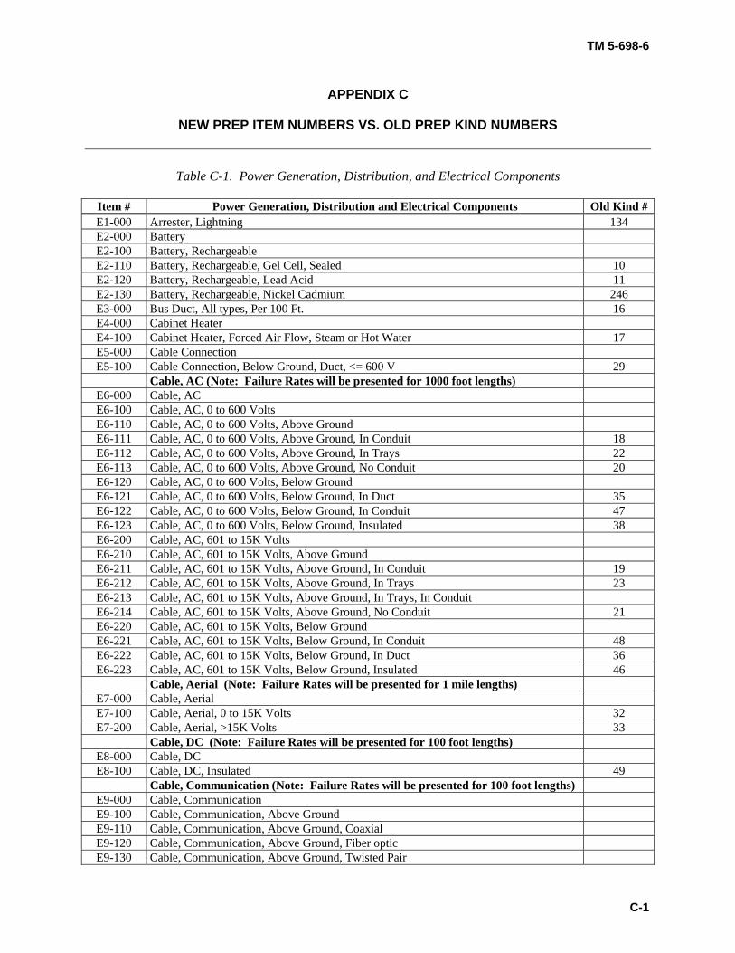
TM 5-698-6
C-1
APPENDIX C
NEW PREP ITEM NUMBERS VS. OLD PREP KIND NUMBERS
Table C-1. Power Generation, Distribution, and Electrical Components
Item # Power Generation, Distribution and Electrical Components Old Kind # E1-000 Arrester, Lightning 134 E2-000 Battery E2-100 Battery, Rechargeable E2-110 Battery, Rechargeable, Gel Cell, Sealed 10 E2-120 Battery, Rechargeable, Lead Acid 11 E2-130 Battery, Rechargeable, Nickel Cadmium 246 E3-000 Bus Duct, All types, Per 100 Ft. 16 E4-000 Cabinet Heater E4-100 Cabinet Heater, Forced Air Flow, Steam or Hot Water 17 E5-000 Cable Connection E5-100 Cable Connection, Below Ground, Duct, <= 600 V 29
Cable, AC (Note: Failure Rates will be presented for 1000 foot lengths) E6-000 Cable, AC E6-100 Cable, AC, 0 to 600 Volts E6-110 Cable, AC, 0 to 600 Volts, Above Ground E6-111 Cable, AC, 0 to 600 Volts, Above Ground, In Conduit 18 E6-112 Cable, AC, 0 to 600 Volts, Above Ground, In Trays 22 E6-113 Cable, AC, 0 to 600 Volts, Above Ground, No Conduit 20 E6-120 Cable, AC, 0 to 600 Volts, Below Ground E6-121 Cable, AC, 0 to 600 Volts, Below Ground, In Duct 35 E6-122 Cable, AC, 0 to 600 Volts, Below Ground, In Conduit 47 E6-123 Cable, AC, 0 to 600 Volts, Below Ground, Insulated 38 E6-200 Cable, AC, 601 to 15K Volts E6-210 Cable, AC, 601 to 15K Volts, Above Ground E6-211 Cable, AC, 601 to 15K Volts, Above Ground, In Conduit 19 E6-212 Cable, AC, 601 to 15K Volts, Above Ground, In Trays 23 E6-213 Cable, AC, 601 to 15K Volts, Above Ground, In Trays, In Conduit E6-214 Cable, AC, 601 to 15K Volts, Above Ground, No Conduit 21 E6-220 Cable, AC, 601 to 15K Volts, Below Ground E6-221 Cable, AC, 601 to 15K Volts, Below Ground, In Conduit 48 E6-222 Cable, AC, 601 to 15K Volts, Below Ground, In Duct 36 E6-223 Cable, AC, 601 to 15K Volts, Below Ground, Insulated 46
Cable, Aerial (Note: Failure Rates will be presented for 1 mile lengths) E7-000 Cable, Aerial E7-100 Cable, Aerial, 0 to 15K Volts 32 E7-200 Cable, Aerial, >15K Volts 33
Cable, DC (Note: Failure Rates will be presented for 100 foot lengths) E8-000 Cable, DC E8-100 Cable, DC, Insulated 49
Cable, Communication (Note: Failure Rates will be presented for 100 foot lengths) E9-000 Cable, Communication E9-100 Cable, Communication, Above Ground E9-110 Cable, Communication, Above Ground, Coaxial E9-120 Cable, Communication, Above Ground, Fiber optic E9-130 Cable, Communication, Above Ground, Twisted Pair
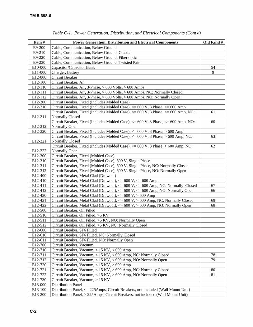
TM 5-698-6
C-2
Table C-1. Power Generation, Distribution, and Electrical Components (Cont'd)
Item # Power Generation, Distribution and Electrical Components Old Kind # E9-200 Cable, Communication, Below Ground E9-210 Cable, Communication, Below Ground, Coaxial E9-220 Cable, Communication, Below Ground, Fiber optic E9-230 Cable, Communication, Below Ground, Twisted Pair E10-000 Capacitor/Capacitor Bank 54 E11-000 Charger, Battery 9 E12-000 Circuit Breaker E12-100 Circuit Breaker, Air E12-110 Circuit Breaker, Air, 3-Phase, > 600 Volts, > 600 Amps E12-111 Circuit Breaker, Air, 3-Phase, > 600 Volts, > 600 Amps, NC: Normally Closed E12-112 Circuit Breaker, Air, 3-Phase, > 600 Volts, > 600 Amps, NO: Normally Open E12-200 Circuit Breaker, Fixed (Includes Molded Case) E12-210 Circuit Breaker, Fixed (Includes Molded Case), <= 600 V, 3 Phase, <= 600 Amp
E12-211 Circuit Breaker, Fixed (Includes Molded Case), <= 600 V, 3 Phase, <= 600 Amp, NC: Normally Closed
61
E12-212 Circuit Breaker, Fixed (Includes Molded Case), <= 600 V, 3 Phase, <= 600 Amp, NO: Normally Open
60
E12-220 Circuit Breaker, Fixed (Includes Molded Case), <= 600 V, 3 Phase, > 600 Amp
E12-221 Circuit Breaker, Fixed (Includes Molded Case), <= 600 V, 3 Phase, > 600 Amp, NC: Normally Closed
63
E12-222 Circuit Breaker, Fixed (Includes Molded Case), <= 600 V, 3 Phase, > 600 Amp, NO: Normally Open
62
E12-300 Circuit Breaker, Fixed (Molded Case) E12-310 Circuit Breaker, Fixed (Molded Case), 600 V, Single Phase E12-311 Circuit Breaker, Fixed (Molded Case), 600 V, Single Phase, NC: Normally Closed E12-312 Circuit Breaker, Fixed (Molded Case), 600 V, Single Phase, NO: Normally Open E12-400 Circuit Breaker, Metal Clad (Drawout) E12-410 Circuit Breaker, Metal Clad (Drawout), <= 600 V, <= 600 Amp E12-411 Circuit Breaker, Metal Clad (Drawout), <= 600 V, <= 600 Amp, NC: Normally Closed 67 E12-412 Circuit Breaker, Metal Clad (Drawout), <= 600 V, <= 600 Amp, NO: Normally Open 66 E12-420 Circuit Breaker, Metal Clad (Drawout), <= 600 V, > 600 Amp E12-421 Circuit Breaker, Metal Clad (Drawout), <= 600 V, > 600 Amp, NC: Normally Closed 69 E12-422 Circuit Breaker, Metal Clad (Drawout), <= 600 V, > 600 Amp, NO: Normally Open 68 E12-500 Circuit Breaker, Oil Filled E12-510 Circuit Breaker, Oil Filled, >5 KV E12-511 Circuit Breaker, Oil Filled, >5 KV, NO: Normally Open E12-512 Circuit Breaker, Oil Filled, >5 KV, NC: Normally Closed E12-600 Circuit Breaker, SF6 Filled E12-610 Circuit Breaker, SF6 Filled, NC: Normally Closed E12-611 Circuit Breaker, SF6 Filled, NO: Normally Open E12-700 Circuit Breaker, Vacuum E12-710 Circuit Breaker, Vacuum, < 15 KV, < 600 Amp E12-711 Circuit Breaker, Vacuum, < 15 KV, < 600 Amp, NC: Normally Closed 78 E12-712 Circuit Breaker, Vacuum, < 15 KV, < 600 Amp, NO: Normally Open 79 E12-720 Circuit Breaker, Vacuum, < 15 KV, > 600 Amp E12-721 Circuit Breaker, Vacuum, < 15 KV, > 600 Amp, NC: Normally Closed 80 E12-722 Circuit Breaker, Vacuum, < 15 KV, > 600 Amp, NO: Normally Open 81 E12-730 Circuit Breaker, Vacuum, > 15 KV E13-000 Distribution Panel E13-100 Distribution Panel, <= 225Amps, Circuit Breakers, not included (Wall Mount Unit) E13-200 Distribution Panel, > 225Amps, Circuit Breakers, not included (Wall Mount Unit)
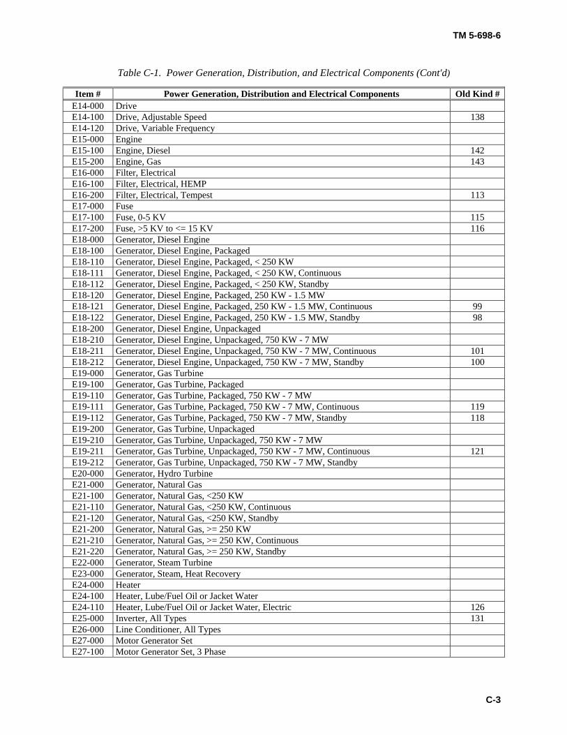
TM 5-698-6
C-3
Table C-1. Power Generation, Distribution, and Electrical Components (Cont'd)
Item # Power Generation, Distribution and Electrical Components Old Kind # E14-000 Drive E14-100 Drive, Adjustable Speed 138 E14-120 Drive, Variable Frequency E15-000 Engine E15-100 Engine, Diesel 142 E15-200 Engine, Gas 143 E16-000 Filter, Electrical E16-100 Filter, Electrical, HEMP E16-200 Filter, Electrical, Tempest 113 E17-000 Fuse E17-100 Fuse, 0-5 KV 115 E17-200 Fuse, >5 KV to <= 15 KV 116 E18-000 Generator, Diesel Engine E18-100 Generator, Diesel Engine, Packaged E18-110 Generator, Diesel Engine, Packaged, < 250 KW E18-111 Generator, Diesel Engine, Packaged, < 250 KW, Continuous E18-112 Generator, Diesel Engine, Packaged, < 250 KW, Standby E18-120 Generator, Diesel Engine, Packaged, 250 KW - 1.5 MW E18-121 Generator, Diesel Engine, Packaged, 250 KW - 1.5 MW, Continuous 99 E18-122 Generator, Diesel Engine, Packaged, 250 KW - 1.5 MW, Standby 98 E18-200 Generator, Diesel Engine, Unpackaged E18-210 Generator, Diesel Engine, Unpackaged, 750 KW - 7 MW E18-211 Generator, Diesel Engine, Unpackaged, 750 KW - 7 MW, Continuous 101 E18-212 Generator, Diesel Engine, Unpackaged, 750 KW - 7 MW, Standby 100 E19-000 Generator, Gas Turbine E19-100 Generator, Gas Turbine, Packaged E19-110 Generator, Gas Turbine, Packaged, 750 KW - 7 MW E19-111 Generator, Gas Turbine, Packaged, 750 KW - 7 MW, Continuous 119 E19-112 Generator, Gas Turbine, Packaged, 750 KW - 7 MW, Standby 118 E19-200 Generator, Gas Turbine, Unpackaged E19-210 Generator, Gas Turbine, Unpackaged, 750 KW - 7 MW E19-211 Generator, Gas Turbine, Unpackaged, 750 KW - 7 MW, Continuous 121 E19-212 Generator, Gas Turbine, Unpackaged, 750 KW - 7 MW, Standby E20-000 Generator, Hydro Turbine E21-000 Generator, Natural Gas E21-100 Generator, Natural Gas, <250 KW E21-110 Generator, Natural Gas, <250 KW, Continuous E21-120 Generator, Natural Gas, <250 KW, Standby E21-200 Generator, Natural Gas, >= 250 KW E21-210 Generator, Natural Gas, >= 250 KW, Continuous E21-220 Generator, Natural Gas, >= 250 KW, Standby E22-000 Generator, Steam Turbine E23-000 Generator, Steam, Heat Recovery E24-000 Heater E24-100 Heater, Lube/Fuel Oil or Jacket Water E24-110 Heater, Lube/Fuel Oil or Jacket Water, Electric 126 E25-000 Inverter, All Types 131 E26-000 Line Conditioner, All Types E27-000 Motor Generator Set E27-100 Motor Generator Set, 3 Phase
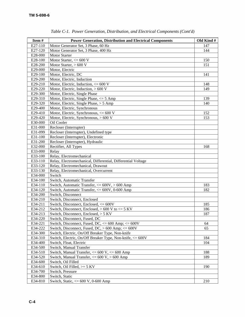
TM 5-698-6
C-4
Table C-1. Power Generation, Distribution, and Electrical Components (Cont'd)
Item # Power Generation, Distribution and Electrical Components Old Kind # E27-110 Motor Generator Set, 3 Phase, 60 Hz 147 E27-120 Motor Generator Set, 3 Phase, 400 Hz 144 E28-000 Motor Starter E28-100 Motor Starter, <= 600 V 150 E28-200 Motor Starter, > 600 V 151 E29-000 Motor, Electric E29-100 Motor, Electric, DC 141 E29-200 Motor, Electric, Induction E29-210 Motor, Electric, Induction, <= 600 V 148 E29-220 Motor, Electric, Induction, > 600 V 149 E29-300 Motor, Electric, Single Phase E29-310 Motor, Electric, Single Phase, <= 5 Amp 139 E29-320 Motor, Electric, Single Phase, > 5 Amp 140 E29-400 Motor, Electric, Synchronous E29-410 Motor, Electric, Synchronous, <= 600 V 152 E29-420 Motor, Electric, Synchronous, > 600 V 153 E30-000 Oil Cooler E31-000 Recloser (Interrupter) E31-099 Recloser (Interrupter), Undefined type E31-100 Recloser (Interrupter), Electronic E31-200 Recloser (Interrupter), Hydraulic E32-000 Rectifier, All Types 168 E33-000 Relay E33-100 Relay, Electromechanical E33-110 Relay, Electromechanical, Differential, Differential Voltage E33-120 Relay, Electromechanical, Drawout E33-130 Relay, Electromechanical, Overcurrent E34-000 Switch E34-100 Switch, Automatic Transfer E34-110 Switch, Automatic Transfer, <= 600V, > 600 Amp 183 E34-120 Switch, Automatic Transfer, <= 600V, 0-600 Amp 182 E34-200 Switch, Disconnect E34-210 Switch, Disconnect, Enclosed E34-211 Switch, Disconnect, Enclosed, <= 600V 185 E34-212 Switch, Disconnect, Enclosed, > 600 V to <= 5 KV 186 E34-213 Switch, Disconnect, Enclosed, > 5 KV 187 E34-220 Switch, Disconnect, Fused, DC E34-221 Switch, Disconnect, Fused, DC, <= 600 Amp; <= 600V 64 E34-222 Switch, Disconnect, Fused, DC, > 600 Amp; <= 600V 65 E34-300 Switch, Electric, On/Off Breaker Type, Non-knife E34-310 Switch, Electric, On/Off Breaker Type, Non-knife, <= 600V 184 E34-400 Switch, Float, Electric 104 E34-500 Switch, Manual Transfer E34-510 Switch, Manual Transfer, <= 600 V, <= 600 Amp 188 E34-520 Switch, Manual Transfer, <= 600 V, > 600 Amp 189 E34-600 Switch, Oil Filled E34-610 Switch, Oil Filled, >= 5 KV 190 E34-700 Switch, Pressure E34-800 Switch, Static E34-810 Switch, Static, <= 600 V, 0-600 Amp 210
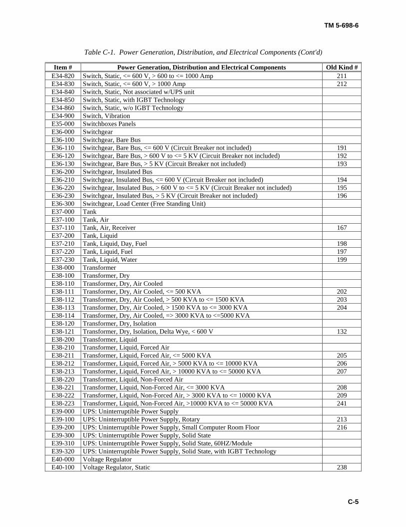
TM 5-698-6
C-5
Table C-1. Power Generation, Distribution, and Electrical Components (Cont'd)
Item # Power Generation, Distribution and Electrical Components Old Kind # E34-820 Switch, Static, <= 600 V, > 600 to <= 1000 Amp 211 E34-830 Switch, Static, <= 600 V, > 1000 Amp 212 E34-840 Switch, Static, Not associated w/UPS unit E34-850 Switch, Static, with IGBT Technology E34-860 Switch, Static, w/o IGBT Technology E34-900 Switch, Vibration E35-000 Switchboxes Panels E36-000 Switchgear E36-100 Switchgear, Bare Bus E36-110 Switchgear, Bare Bus, <= 600 V (Circuit Breaker not included) 191 E36-120 Switchgear, Bare Bus, > 600 V to <= 5 KV (Circuit Breaker not included) 192 E36-130 Switchgear, Bare Bus, > 5 KV (Circuit Breaker not included) 193 E36-200 Switchgear, Insulated Bus E36-210 Switchgear, Insulated Bus, <= 600 V (Circuit Breaker not included) 194 E36-220 Switchgear, Insulated Bus, > 600 V to <= 5 KV (Circuit Breaker not included) 195 E36-230 Switchgear, Insulated Bus, > 5 KV (Circuit Breaker not included) 196 E36-300 Switchgear, Load Center (Free Standing Unit) E37-000 Tank E37-100 Tank, Air E37-110 Tank, Air, Receiver 167 E37-200 Tank, Liquid E37-210 Tank, Liquid, Day, Fuel 198 E37-220 Tank, Liquid, Fuel 197 E37-230 Tank, Liquid, Water 199 E38-000 Transformer E38-100 Transformer, Dry E38-110 Transformer, Dry, Air Cooled E38-111 Transformer, Dry, Air Cooled, <= 500 KVA 202 E38-112 Transformer, Dry, Air Cooled, > 500 KVA to <= 1500 KVA 203 E38-113 Transformer, Dry, Air Cooled, > 1500 KVA to <= 3000 KVA 204 E38-114 Transformer, Dry, Air Cooled, => 3000 KVA to <=5000 KVA E38-120 Transformer, Dry, Isolation E38-121 Transformer, Dry, Isolation, Delta Wye, < 600 V 132 E38-200 Transformer, Liquid E38-210 Transformer, Liquid, Forced Air E38-211 Transformer, Liquid, Forced Air, <= 5000 KVA 205 E38-212 Transformer, Liquid, Forced Air, > 5000 KVA to <= 10000 KVA 206 E38-213 Transformer, Liquid, Forced Air, > 10000 KVA to <= 50000 KVA 207 E38-220 Transformer, Liquid, Non-Forced Air E38-221 Transformer, Liquid, Non-Forced Air, <= 3000 KVA 208 E38-222 Transformer, Liquid, Non-Forced Air, > 3000 KVA to <= 10000 KVA 209 E38-223 Transformer, Liquid, Non-Forced Air, >10000 KVA to <= 50000 KVA 241 E39-000 UPS: Uninterruptible Power Supply E39-100 UPS: Uninterruptible Power Supply, Rotary 213 E39-200 UPS: Uninterruptible Power Supply, Small Computer Room Floor 216 E39-300 UPS: Uninterruptible Power Supply, Solid State E39-310 UPS: Uninterruptible Power Supply, Solid State, 60HZ/Module E39-320 UPS: Uninterruptible Power Supply, Solid State, with IGBT Technology E40-000 Voltage Regulator E40-100 Voltage Regulator, Static 238
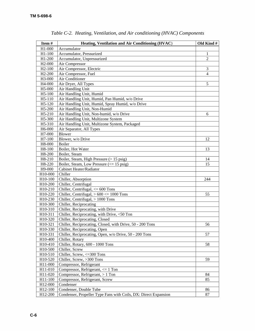
TM 5-698-6
C-6
Table C-2. Heating, Ventilation, and Air conditioning (HVAC) Components
Item # Heating, Ventilation and Air Conditioning (HVAC) Old Kind #H1-000 Accumulator H1-100 Accumulator, Pressurized 1 H1-200 Accumulator, Unpressurized 2 H2-000 Air Compressor H2-100 Air Compressor, Electric 3 H2-200 Air Compressor, Fuel 4 H3-000 Air Conditioner H4-000 Air Dryer, All Types 5 H5-000 Air Handling Unit H5-100 Air Handling Unit, Humid H5-110 Air Handling Unit, Humid, Pan Humid, w/o Drive H5-120 Air Handling Unit, Humid, Spray Humid, w/o Drive H5-200 Air Handling Unit, Non-Humid H5-210 Air Handling Unit, Non-humid, w/o Drive 6 H5-300 Air Handling Unit, Multizone System H5-310 Air Handling Unit, Multizone System, Packaged H6-000 Air Separator, All Types H7-000 Blower H7-100 Blower, w/o Drive 12 H8-000 Boiler H8-100 Boiler, Hot Water 13 H8-200 Boiler, Steam H8-210 Boiler, Steam, High Pressure (> 15 psig) 14 H8-220 Boiler, Steam, Low Pressure (<= 15 psig) 15 H9-000 Cabinet Heater/Radiator
H10-000 Chiller H10-100 Chiller, Absorption 244 H10-200 Chiller, Centrifugal H10-210 Chiller, Centrifugal, <= 600 Tons H10-220 Chiller, Centrifugal, > 600 <= 1000 Tons 55 H10-230 Chiller, Centrifugal, > 1000 Tons H10-300 Chiller, Reciprocating H10-310 Chiller, Reciprocating, with Drive H10-311 Chiller, Reciprocating, with Drive, <50 Ton H10-320 Chiller, Reciprocating, Closed H10-321 Chiller, Reciprocating, Closed, with Drive, 50 - 200 Tons 56 H10-330 Chiller, Reciprocating, Open H10-331 Chiller, Reciprocating, Open, w/o Drive, 50 - 200 Tons 57 H10-400 Chiller, Rotary H10-410 Chiller, Rotary, 600 - 1000 Tons 58 H10-500 Chiller, Screw H10-510 Chiller, Screw, <=300 Tons H10-520 Chiller, Screw, >300 Tons 59 H11-000 Compressor, Refrigerant H11-010 Compressor, Refrigerant, <= 1 Ton H11-020 Compressor, Refrigerant, > 1 Ton 84 H11-100 Compressor, Refrigerant, Screw 85 H12-000 Condenser H12-100 Condenser, Double Tube 86 H12-200 Condenser, Propeller Type Fans with Coils, DX: Direct Expansion 87
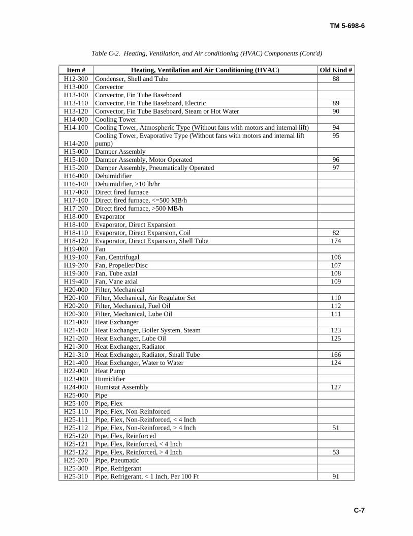
TM 5-698-6
C-7
Table C-2. Heating, Ventilation, and Air conditioning (HVAC) Components (Cont'd)
Item # Heating, Ventilation and Air Conditioning (HVAC) Old Kind #H12-300 Condenser, Shell and Tube 88 H13-000 Convector H13-100 Convector, Fin Tube Baseboard H13-110 Convector, Fin Tube Baseboard, Electric 89 H13-120 Convector, Fin Tube Baseboard, Steam or Hot Water 90 H14-000 Cooling Tower H14-100 Cooling Tower, Atmospheric Type (Without fans with motors and internal lift) 94
H14-200 Cooling Tower, Evaporative Type (Without fans with motors and internal lift pump)
95
H15-000 Damper Assembly H15-100 Damper Assembly, Motor Operated 96 H15-200 Damper Assembly, Pneumatically Operated 97 H16-000 Dehumidifier H16-100 Dehumidifier, >10 lb/hr H17-000 Direct fired furnace H17-100 Direct fired furnace, <=500 MB/h H17-200 Direct fired furnace, >500 MB/h H18-000 Evaporator H18-100 Evaporator, Direct Expansion H18-110 Evaporator, Direct Expansion, Coil 82 H18-120 Evaporator, Direct Expansion, Shell Tube 174 H19-000 Fan H19-100 Fan, Centrifugal 106 H19-200 Fan, Propeller/Disc 107 H19-300 Fan, Tube axial 108 H19-400 Fan, Vane axial 109 H20-000 Filter, Mechanical H20-100 Filter, Mechanical, Air Regulator Set 110 H20-200 Filter, Mechanical, Fuel Oil 112 H20-300 Filter, Mechanical, Lube Oil 111 H21-000 Heat Exchanger H21-100 Heat Exchanger, Boiler System, Steam 123 H21-200 Heat Exchanger, Lube Oil 125 H21-300 Heat Exchanger, Radiator H21-310 Heat Exchanger, Radiator, Small Tube 166 H21-400 Heat Exchanger, Water to Water 124 H22-000 Heat Pump H23-000 Humidifier H24-000 Humistat Assembly 127 H25-000 Pipe H25-100 Pipe, Flex H25-110 Pipe, Flex, Non-Reinforced H25-111 Pipe, Flex, Non-Reinforced, < 4 Inch H25-112 Pipe, Flex, Non-Reinforced, > 4 Inch 51 H25-120 Pipe, Flex, Reinforced H25-121 Pipe, Flex, Reinforced, < 4 Inch H25-122 Pipe, Flex, Reinforced, > 4 Inch 53 H25-200 Pipe, Pneumatic H25-300 Pipe, Refrigerant H25-310 Pipe, Refrigerant, < 1 Inch, Per 100 Ft 91
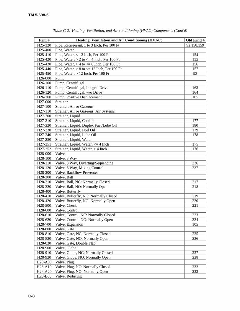
TM 5-698-6
C-8
Table C-2. Heating, Ventilation, and Air conditioning (HVAC) Components (Cont'd)
Item # Heating, Ventilation and Air Conditioning (HVAC) Old Kind #H25-320 Pipe, Refrigerant, 1 to 3 Inch, Per 100 Ft 92,158,159H25-400 Pipe, Water H25-410 Pipe, Water, <= 2 Inch, Per 100 Ft 154 H25-420 Pipe, Water, > 2 to <= 4 Inch, Per 100 Ft 155 H25-430 Pipe, Water, > 4 to <= 8 Inch, Per 100 Ft 156 H25-440 Pipe, Water, > 8 to <= 12 Inch, Per 100 Ft 157 H25-450 Pipe, Water, > 12 Inch, Per 100 Ft 93 H26-000 Pump H26-100 Pump, Centrifugal H26-110 Pump, Centrifugal, Integral Drive 163 H26-120 Pump, Centrifugal, w/o Drive 164 H26-200 Pump, Positive Displacement 165 H27-000 Strainer H27-100 Strainer, Air or Gaseous H27-110 Strainer, Air or Gaseous, Air Systems H27-200 Strainer, Liquid H27-210 Strainer, Liquid, Coolant 177 H27-220 Strainer, Liquid, Duplex Fuel/Lube Oil 180 H27-230 Strainer, Liquid, Fuel Oil 179 H27-240 Strainer, Liquid, Lube Oil 178 H27-250 Strainer, Liquid, Water H27-251 Strainer, Liquid, Water, <= 4 Inch 175 H27-252 Strainer, Liquid, Water, > 4 Inch 176 H28-000 Valve H28-100 Valve, 3 Way H28-110 Valve, 3 Way, Diverting/Sequencing 236 H28-120 Valve, 3 Way, Mixing Control 237 H28-200 Valve, Backflow Preventer H28-300 Valve, Ball H28-310 Valve, Ball, NC: Normally Closed 217 H28-320 Valve, Ball, NO: Normally Open 218 H28-400 Valve, Butterfly H28-410 Valve, Butterfly, NC: Normally Closed 219 H28-420 Valve, Butterfly, NO: Normally Open 220 H28-500 Valve, Check 221 H28-600 Valve, Control H28-610 Valve, Control, NC: Normally Closed 223 H28-620 Valve, Control, NO: Normally Open 224 H28-700 Valve, Expansion 105 H28-800 Valve, Gate H28-810 Valve, Gate, NC: Normally Closed 225 H28-820 Valve, Gate, NO: Normally Open 226 H28-830 Valve, Gate, Double Flap H28-900 Valve, Globe H28-910 Valve, Globe, NC: Normally Closed 227 H28-920 Valve, Globe, NO: Normally Open 228 H28-A00 Valve, Plug H28-A10 Valve, Plug, NC: Normally Closed 232 H28-A20 Valve, Plug, NO: Normally Open 233 H28-B00 Valve, Reducing
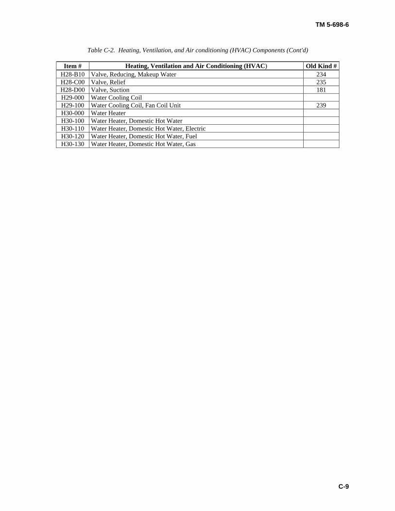
TM 5-698-6
C-9
Table C-2. Heating, Ventilation, and Air conditioning (HVAC) Components (Cont'd)
Item # Heating, Ventilation and Air Conditioning (HVAC) Old Kind #H28-B10 Valve, Reducing, Makeup Water 234 H28-C00 Valve, Relief 235 H28-D00 Valve, Suction 181 H29-000 Water Cooling Coil H29-100 Water Cooling Coil, Fan Coil Unit 239 H30-000 Water Heater H30-100 Water Heater, Domestic Hot Water H30-110 Water Heater, Domestic Hot Water, Electric H30-120 Water Heater, Domestic Hot Water, Fuel H30-130 Water Heater, Domestic Hot Water, Gas
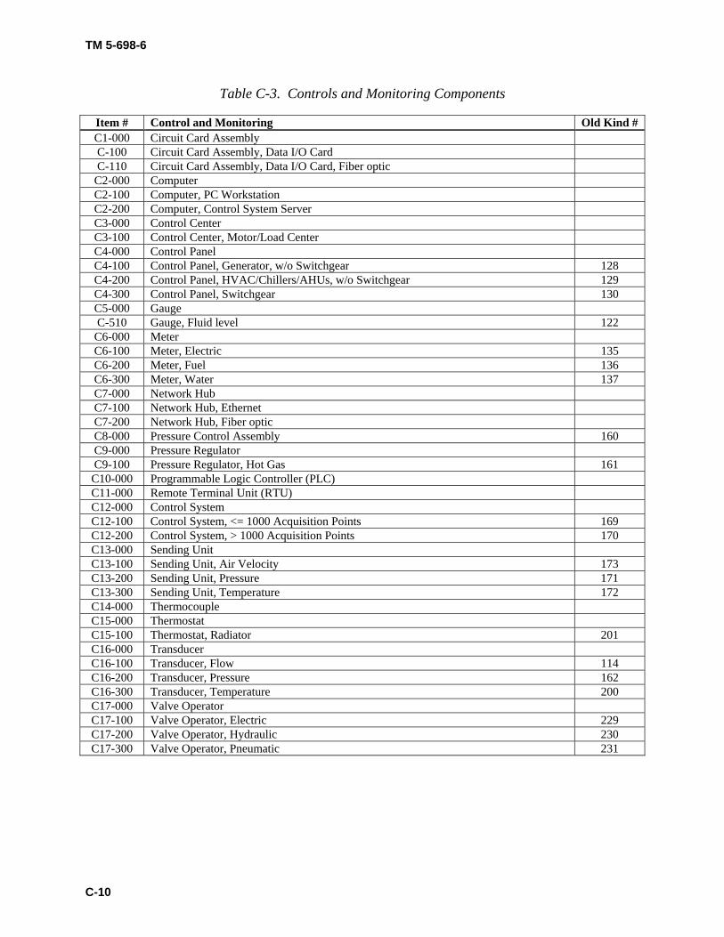
TM 5-698-6
C-10
Table C-3. Controls and Monitoring Components
Item # Control and Monitoring Old Kind # C1-000 Circuit Card Assembly C-100 Circuit Card Assembly, Data I/O Card C-110 Circuit Card Assembly, Data I/O Card, Fiber optic
C2-000 Computer C2-100 Computer, PC Workstation C2-200 Computer, Control System Server C3-000 Control Center C3-100 Control Center, Motor/Load Center C4-000 Control Panel C4-100 Control Panel, Generator, w/o Switchgear 128 C4-200 Control Panel, HVAC/Chillers/AHUs, w/o Switchgear 129 C4-300 Control Panel, Switchgear 130 C5-000 Gauge C-510 Gauge, Fluid level 122
C6-000 Meter C6-100 Meter, Electric 135 C6-200 Meter, Fuel 136 C6-300 Meter, Water 137 C7-000 Network Hub C7-100 Network Hub, Ethernet C7-200 Network Hub, Fiber optic C8-000 Pressure Control Assembly 160 C9-000 Pressure Regulator C9-100 Pressure Regulator, Hot Gas 161 C10-000 Programmable Logic Controller (PLC) C11-000 Remote Terminal Unit (RTU) C12-000 Control System C12-100 Control System, <= 1000 Acquisition Points 169 C12-200 Control System, > 1000 Acquisition Points 170 C13-000 Sending Unit C13-100 Sending Unit, Air Velocity 173 C13-200 Sending Unit, Pressure 171 C13-300 Sending Unit, Temperature 172 C14-000 Thermocouple C15-000 Thermostat C15-100 Thermostat, Radiator 201 C16-000 Transducer C16-100 Transducer, Flow 114 C16-200 Transducer, Pressure 162 C16-300 Transducer, Temperature 200 C17-000 Valve Operator C17-100 Valve Operator, Electric 229 C17-200 Valve Operator, Hydraulic 230 C17-300 Valve Operator, Pneumatic 231
TM 5-698-6
G-1
GLOSSARY
1. Glossary
-A-
AVAILABILITY, INHERENT (Ai). The instantaneous probability that a component will be up. Ai considers only downtime for repair due to failures. No logistics delay time, preventative maintenance, etc. is included.
AVAILABILITY, OPERATIONAL (Ao). Ao is the instantaneous probability that a component will be up but differs from inherent availability in that it includes ALL downtime. Included is downtime for both corrective maintenance and preventative maintenance, including any logistics delay time.
-C- COMPONENT. A piece of electrical or mechanical equipment viewed as an entity for the purpose of reliability evaluation CORRECTIVE MAINTENANCE (CM): All actions performed as a result of failure, to restore an item to a specified condition. Corrective maintenance can include any or all of the following steps: Lo-calization, Isolation, Disassembly, Interchange, Reassembly, Alignment and Checkout.
-D- DOWNTIME: That element of time during which an item is in an operational inventory but is not in condition to perform its required function.
-F- FAILURE (f). The termination of the ability of a component or system to perform a required function. FAILURE RATE (λ): The mean (arithmetic average, also known as the forced outage rate) number of failures of a component and/or system per unit exposure time. The most common unit in reliability analy-ses is hours (h).However, some industries use failures per year (f/y) which is denoted by the symbol (λy).
-L- LOGISTIC DELAY TIME: That element of downtime during which no maintenance is being accom-plished on the item because of either supply or administrative delay.
-M- MAINTENANCE: All actions necessary for retaining an item in or restoring it to a specified condition.
TM 5-698-6
G-2
MEAN DOWNTIME (MDT). The average downtime caused by preventative and corrective mainte-nance, including any logistics delay time. This is synonymous with mean time to restore system (MTTRS) as found in some publications. MEAN TIME BETWEEN FAILURES (MTBF). The mean exposure time between consecutive fail-ures of a component. MTBF is a require measurement used for calculating inherent availability. It can be estimated by dividing the exposure time by the number of failures in that period. MEAN TIME BETWEEN MAINTENANCE (MTBM). The average time between all maintenance events that cause downtime, both preventative and corrective maintenance, and also includes any associ-ated logistics delay time. MEAN TIME TO MAINTAIN (MTTM). The average downtime for preventative maintenance. This includes any logistics delay time. MEAN TIME TO REPAIR (MTTR). The mean time to replace or repair a failed component. Logistics delay time associated with the repair, such as parts acquisitions, crew mobilization, are not included. It can be estimated by dividing the summation of repair times by the number of repairs and, therefore, is practically the average repair time. The most common unit in reliability analyses is hours (h/f).
-P- PREVENTATIVE MAINTENANCE (PM): All actions performed in an attempt to retain an item in a specified condition. These actions may or may not result in downtime for the component, and may or may not be performed on a fixed interval.
-R- RELIABILITY (R(t)). The probability that a component can perform its intended function for a speci-fied time interval (t) under stated conditions. This calculation is based on the exponential distribution.
TM 5-698-6 The proponent agency of this publication is the Chief of Engineers, United States Army. Users are invited to send comments and suggested improvements on DA Form 2028 (Recommended Changes to Publications and Blank Forms) directly to HQUSACE, (ATTN: CEMP-OS-P), Washington, DC 20314-1000.
Distribution:
To be distributed in accordance with Initial Distribution Number (IDN) 344856, requirements for non-equipment TM 5-698-6.
By Order of the Secretary of the Army:
PETER J. SCHOOMAKER General, United States Army
Chief of Staff Official:
JOYCE E. MORROW Administrative Assistant to the
Secretary of the Army

PIN: 083640-000