Embed Size (px)
Citation preview
Prepared by
for the California High-Speed Rail Authority
California High-Speed Train Project
TECHNICAL MEMORANDUM
Turnouts and Yard Tracks TM 2.1.8
Prepared by: Signed document on file_________ 21 June 09 George Harris Date
Checked by: Signed document on file_________ 15 July 09
Thomas Carroll Date Approved by: Signed document on file_________ 17 July 09
Ken Jong, PE, Engineering Manager Date Released by: Signed document on file_________ 21 July 09
Anthony Daniels, Program Director Date
Revision Date Description 0 17 July 09 Initial Release, R0
Note: Signatures apply for the latest technical memorandum revision as noted above.
California High-Speed Train Project Turnouts and Yard Tracks, R0
CALIFORNIA HIGH-SPEED RAIL AUTHORITY
This document has been prepared by Parsons Brinckerhoff for the California High-Speed Rail Authority and for application to the California High-Speed Train Project. Any use of this document for purposes other than this Project, or the specific portion of the Project stated in the document, shall be at the sole risk of the user, and without liability to PB for any losses or injuries arising for such use.
California High-Speed Train Project Turnouts and Yard Tracks, R0
CALIFORNIA HIGH-SPEED RAIL AUTHORITY
Page ii
System Level Technical and Integration Reviews The purpose of the review is to ensure: - Technical consistency and appropriateness - Check for integration issues and conflicts System level reviews are required for all technical memoranda. Technical Leads for each subsystem are responsible for completing the reviews in a timely manner and identifying appropriate senior staff to perform the review. Exemption to the System Level technical and integration review by any Subsystem must be approved by the Engineering Manager. System Level Technical Reviews by Subsystem: Systems: _NOT REQUIRED______________ _________ Date Infrastructure: Signed document on file_________ 11 July 09 Thomas Carroll Date Operations: Signed document on file_________ 11 July 09 Paul Mosier Date Maintenance: Signed document on file_________ 11 July 09 Paul Mosier Date Rolling Stock: Signed document on file_________ 06 July 09 Frank Banko Date
Note: Signatures apply for the technical memorandum revision corresponding to revision number in header and as noted on cover.
California High-Speed Train Project Turnouts and Yard Tracks, R0
CALIFORNIA HIGH-SPEED RAIL AUTHORITY
Page iii
TABLE OF CONTENTS
ABSTRACT .................................................................................................................... 1
1.0 INTRODUCTION .................................................................................................. 2
1.1 PURPOSE OF TECHNICAL MEMORANDUM .................................................................. 2
1.2 STATEMENT OF TECHNICAL ISSUE ............................................................................ 2
1.3 CONCEPTS AND DEFINITIONS ................................................................................... 2 1.3.1 DEFINITION OF TERMS ...................................................................................................................... 2 1.3.2 UNITS .............................................................................................................................................. 3
2.0 DEFINITION OF TECHNICAL TOPIC .................................................................. 4
2.1 GENERAL ............................................................................................................... 4
2.2 LAWS AND CODES .................................................................................................. 4
2.3 DESIGN STANDARDS ............................................................................................... 4 2.3.1 DESIGN STANDARDS FOR CONSTRUCTION ......................................................................................... 5 2.3.2 MAINTENANCE STANDARDS .............................................................................................................. 5 2.3.3 SAFETY STANDARDS ........................................................................................................................ 5
3.0 ASSESSMENT / ANALYSIS ................................................................................ 6
3.1 YARD ACCESS TRACKS; YARD, STORAGE, AND OTHER LOW SPEED TRACKS ............. 6 3.1.1 TRACK ALIGNMENT DESIGN PARAMETERS – ACCESS AND MAIN LINE CONNECTING TRACKS ................ 6 3.1.2 TRACK ALIGNMENT DESIGN PARAMETERS – CONNECTING AND SWITCHING TRACKS ............................ 8 3.1.3 TRACK ALIGNMENT DESIGN PARAMETERS – SERVICING AND STORAGE TRACKS .................................. 9
3.2 TURNOUTS ........................................................................................................... 10 3.2.1 DIFFERENCES IN METHOD OF DESCRIPTION AND ANALYSIS .............................................................. 10 3.2.2 TURNOUT GEOMETRY ..................................................................................................................... 11 3.2.3 SELECTED YARD TURNOUTS ........................................................................................................... 11 3.2.4 SPACE BETWEEN TURNOUTS .......................................................................................................... 12 3.2.5 SPACE BESIDE TURNOUTS .............................................................................................................. 12
3.3 CROSSOVERS ....................................................................................................... 13 3.3.1 SINGLE CROSSOVERS .................................................................................................................... 13 3.3.2 DOUBLE CROSSOVERS (SCISSORS CROSSOVERS) .......................................................................... 14
3.4 TRACK LADDERS .................................................................................................. 14 3.4.1 SIMPLE LADDERS ........................................................................................................................... 14 3.4.2 DOUBLE ANGLE LADDERS ............................................................................................................... 15
4.0 SUMMARY AND RECOMMENDATIONS .......................................................... 18
5.0 SOURCE INFORMATION AND REFERENCES ................................................ 19
6.0 DESIGN MANUAL CRITERIA ........................................................................... 20
California High-Speed Train Project Turnouts and Yard Tracks, R0
CALIFORNIA HIGH-SPEED RAIL AUTHORITY
Page iv
6.1 YARD ACCESS TRACKS; YARD, STORAGE, AND OTHER LOW SPEED TRACKS ........... 20 6.1.1 TRACK ALIGNMENT DESIGN PARAMETERS – ACCESS AND MAIN LINE CONNECTING TRACKS .............. 20 6.1.2 TRACK ALIGNMENT DESIGN PARAMETERS – CONNECTING AND SWITCHING TRACKS .......................... 22 6.1.3 TRACK ALIGNMENT DESIGN PARAMETERS – SERVICING AND STORAGE TRACKS ................................ 23
6.2 TURNOUT GEOMETRY ............................................................................................ 24 6.2.1 SELECTED YARD TURNOUTS ........................................................................................................... 25 6.2.2 SPACE BETWEEN TURNOUTS .......................................................................................................... 25 6.2.3 SPACE BESIDE TURNOUTS .............................................................................................................. 26
6.3 CROSSOVERS ....................................................................................................... 26 6.3.1 SINGLE CROSSOVERS .................................................................................................................... 26 6.3.2 DOUBLE CROSSOVERS (SCISSORS CROSSOVERS) .......................................................................... 27
6.4 TRACK LADDERS .................................................................................................. 28 6.4.1 SIMPLE LADDERS ........................................................................................................................... 28 6.4.2 DOUBLE ANGLE LADDERS ............................................................................................................... 28
California High-Speed Train Project Turnouts and Yard Tracks, R0
CALIFORNIA HIGH-SPEED RAIL AUTHORITY
Page 1
ABSTRACT This technical memorandum presents guidance for the geometric design of turnouts, crossovers, yard lead and yard tracks with turnouts and return curves to be used in the basic design in order to achieve a safe and reliable operating railway that meet applicable regulatory requirements and achieve the operational and performance requirements for equipment traveling on California High-Speed Train (CHST) rail lines.
This technical memorandum develops and presents the specific geometric designs to be used in turnouts, crossovers and yard tracks.
This technical memorandum is not a specification for track materials or track construction but is the guideline for the development of those specifications.
This technical memorandum will not include analysis or discussion of the operation of turnouts.
This technical memorandum will not discuss the spacing, nature, and length of yard tracks for specific purposes. Such items are part of the operational requirements.
The information presented in this technical memorandum will be included in the CHSTP Design Manual.
California High-Speed Train Project Turnouts and Yard Tracks, R0
CALIFORNIA HIGH-SPEED RAIL AUTHORITY
Page 2
1.0 INTRODUCTION This Technical Memorandum presents the basis of design for low speed turnout geometry as it relates to yard tracks. The geometric design will be the same regardless of the track form on which it is constructed. It also presents preliminary information on development of other low speed track layouts that involve turnouts and crossovers. Components and track material will be discussed as relevant to geometric issues and no further.
This Technical Memorandum is not intended to be a specification for track materials or track construction. It is intended to be the basis for the development of the specification for those items. For general track information on such items as basic track materials, fastenings, and supports, reference the Technical Memorandum on Track.
Following review, specific guidance in this technical memorandum will be excerpted for inclusion in the CHSTP Design Manual.
1.1 PURPOSE OF TECHNICAL MEMORANDUM The purpose of this technical memorandum is to develop the yard turnout, crossover, and connection track geometries to be used in the CHSTP system.
1.2 STATEMENT OF TECHNICAL ISSUE The objective is to develop turnout geometries appropriate to the nature and speed of the trains to be operated.
1.3 CONCEPTS AND DEFINITIONS
1.3.1 Definition of Terms Technical terms and acronyms will use common American terminology. A number of common terms are different between American and European terminology. European term will be noted in the following definitions and as appropriate elsewhere, but otherwise will not normally be used.
Unless otherwise noted, definitions are either identical to or closely based on the definitions found in either The American Engineering and Maintenance of Way Association’s Manual for Railway Engineering (AREMA Manual) or The Dictionary of Railway Track Terms by Christopher F. Schulte, Simmons Boardman Publishing, 1990.
Parts of a turnout:
• Frog: Commonly called a Crossing in European terminology.
Fixed Frog: Term essentially synonymous with Frog. Sometimes used on railroad systems that also use spring frogs and swing nose frogs in order to clarify the type of frog used in a given situation.
Spring Frog: A frog without fillers between the frog point and one wing rail and with springs holding that wing rail up against the frog point. The other wing rail is fixed. Main track traffic travels on the fixed wing side of the frog. The wheels of diverging side traffic opens the sprung wing rail which is then forced closed by the spring after the wheel has passed. Spring frogs are either right handed or left handed. These devices are normally used only where the traffic on the side springing the wing rail is 20% or less of the total traffic over the frog. These devices are generally unknown outside North America.
Swing Nose Frog: A frog in a turnout with a movable frog point connected to a switch machine, which moves the point from side to side to provide routes for straight or diverging movements.
California High-Speed Train Project Turnouts and Yard Tracks, R0
CALIFORNIA HIGH-SPEED RAIL AUTHORITY
Page 3
Point of Frog: In American terminology, the point where the gauge lines are ½ inch apart, or the point located one-half the frog number in inches from the intersection of the gauge lines of the rails through the frog. In European terminology, the point of intersections of the gauge lines of the rails through the frog.
Heel of Frog: End of rails that are part of the frog assembly on the end away from the switch
Toe of Frog: End of rails that are part of the frog assembly on the end toward the switch.
• Lead: American definition: The distance from the actual point of switch to the ½ inch point of frog. European definition: The nearest European equivalent would be the distance from the theoretical beginning of the turnout curve at the switch end to the theoretical point of frog.
• Switch: The component of a Turnout consisting of switch rails and connecting parts providing a means for making a path over which to transfer rolling stock from one track to another.
Split Switch: Synonymous with Switch on modern railroads.
Secant Point Switch: A switch point in which the arc of the radius of the switch rail or the turnout itself crosses the gauge line of the stock rail. American standard switch rails are Secant Point Switches.
Tangent Point Switch: A switch point in which the arc of the radius of the switch rail or the turnout itself matches the gauge line of the stock rail. European and most other turnouts are designed to be Tangent Point Switches.
1.3.2 Units The California High-Speed Train Project is based on U.S. Customary Units consistent with guidelines prepared by the California Department of Transportation and defined by the National Institute of Standards and Technology (NIST). U.S. Customary Units are officially used in the United States, and are also known in the US as “English” or “Imperial” units. In order to avoid any confusion, all formal references to units of measure shall be made in terms of U.S. Customary Units. Guidance for units of measure terminology, values, and conversions can be found in the Caltrans Metric Program Transitional Plan, Appendice B U.S. Customary General Primer (http://www.dot.ca.gov/hq/oppd/metric/TransitionPlan/Appendice-B-US-Customary-General-Primer.pdf). Caltrans Metric Program Transitional Plan, Appendice B can also be found as an attachment to the CHSTP Mapping and Survey Technical Memorandum.
California High-Speed Train Project Turnouts and Yard Tracks, R0
CALIFORNIA HIGH-SPEED RAIL AUTHORITY
Page 4
2.0 DEFINITION OF TECHNICAL TOPIC 2.1 GENERAL
The general basis for standards shall be the AREMA Manual and Portfolio. Some reference and use will be made to European standards where appropriate.
2.2 LAWS AND CODES There is no one single law or code or design standard currently in existence that can be followed to produce a high-speed railroad appropriate to the intended purpose and use anticipated. Reference is frequently made to FRA Track Safety Standards. However, these are not design standard in the normal sense.
The Infrastructure TSI (cited below) also offers very limited guidance, primarily related to limitations on change in lateral acceleration, use of movable frogs, and flangeway and locking requirements.
In case of differing values or conflicts in the various requirements among the various design requirements and between any of them and the following design guidelines, the standard followed shall be that which results in the highest level of satisfaction of all requirements or that is deemed the most appropriate.
These various codes and standards include but are not necessarily limited to the following:
Certain requirements of the Federal Railroad Administration (FRA), among them:
• CFR Part 213, Track Safety Standards.
Other Design Guidelines:
• The Manual for Railway Engineering of the American Railway Engineering and Maintenance of Way Association (AREMA Manual), in particular the following chapters:
o Chapter 4: Rail o Chapter 5: Track
• The AREMA Portfolio of Trackwork Plans, commonly referenced as the AREMA Portfolio.
• California Public Utilities Commission (PUC) General Orders (GO), among them: GO 26: Clearances On Railroads And Street Railroads as to Side and Overhead
Structures, Parallel Tracks and Crossings GO 164: Rules and Regulations Governing State Safety Oversight of Rail Fixed
Guideway Systems
• Union Pacific Railroad: See www.uprr.com/aboutup/operations/specs/track/index.shtml for certain of their engineering standards. See www.uprr.com/reus/roadxing/cross_cal.shtml for the Manager of Industry and Public Projects for guidance to further information.
Headquarters address: 1400 Douglas Street Omaha, NE 68179-1001
• Peninsula Corridor Joint Powers Board (Caltrain): For engineering standards, go to http://www.caltrain.com/engineeringstandards.html
The latest version of the above standards shall be the one applicable.
2.3 DESIGN STANDARDS Three different standards are generally applied to railroad design and maintenance, which are summarized herein. This document applies to design standards for construction, which define the initial build condition. Maintenance standards are less rigorous and define the standards to which
California High-Speed Train Project Turnouts and Yard Tracks, R0
CALIFORNIA HIGH-SPEED RAIL AUTHORITY
Page 5
the track may be allowed to wear and deteriorate before maintenance effort need be applied. Safety standards are less rigorous still and define the standards below which the track is regarded as unable to perform its function at the design speed. Safety standards are subject to determination by the Federal Railroad Administration (FRA).
2.3.1 Design Standards for Construction These are the minimum standards of alignment deviation that shall appear in the construction specification. Meeting or exceeding these standards shall also be requirement for the track condition following any adjustments or maintenance work. Allowance for defective materials and components should be very low or nil.
2.3.2 Maintenance Standards These are the minimum standards to which the track may be allowed to deteriorate before maintenance work is required by policy. These standards will include both geometric deviations and component wear / deterioration / degradation considerations. The worst-case for these standards should be no more than half way toward the limits that are determined to be safety standards.
2.3.3 Safety Standards These are the minimum standards to which the track may be allowed to deteriorate before the speed must be reduced or traffic must be halted altogether. These standards will include both geometric deviations and component wear / deterioration / degradation considerations.
California High-Speed Train Project Turnouts and Yard Tracks, R0
CALIFORNIA HIGH-SPEED RAIL AUTHORITY
Page 6
3.0 ASSESSMENT / ANALYSIS 3.1 YARD ACCESS TRACKS; YARD, STORAGE, AND OTHER LOW SPEED TRACKS
The specific track arrangement for each yard will depend upon the purpose of the yard and tracks in the yard. Therefore the basic layout will be determined by operational requirements. The requirements developed in this Technical Memorandum are therefore limited to those of a general nature except for those relating to geometric constraints due to:
• Curvature related constraints due to vehicle characteristics
• Track length constraints due to train and individual vehicle length
• Profile and grade related issues
Other than the tracks connecting the yards to the revenue tracks, the track design parameters are speed-independent.
3.1.1 Track Alignment Design Parameters – Access and Main Line Connecting Tracks Main Line Connecting Tracks: Because suitable yard sites near the main routes and terminals are limited, there may be large distances between main line access points and yards. For the purpose of minimizing time into and out of yards, and minimizing the time required to clear revenue tracks, the tracks connecting main lines to yard shall be designed to higher speed standards than the yard itself. These tracks shall therefore be designed like a secondary main line railroad.
Since speed of trains on these tracks is likely to be highly variable, including the likelihood that trains may frequently be stopped on these tracks, superelevation shall be kept to low values to the greatest extent practical.
• Minimum Radius:
Desirable: 2,500 feet
Minimum: 900 feet
Exceptional: 500 feet
• Design Speed:
Desirable: 50 mph
Minimum: 35 mph
Exceptional: 25 mph
• Curve Radii shall be based on the allowed superelevation and unbalance for the selected speed based on the following limits for superelevation and unbalanced superelevation:
• Superelevation
Desirable: 2 inches or less
Maximum: 3 inches
Exceptional: 3 inches
• Unbalanced Superelevation
Desirable: 2 inches or less
Minimum: 3 inches
Exceptional: 3 inches
California High-Speed Train Project Turnouts and Yard Tracks, R0
CALIFORNIA HIGH-SPEED RAIL AUTHORITY
Page 7
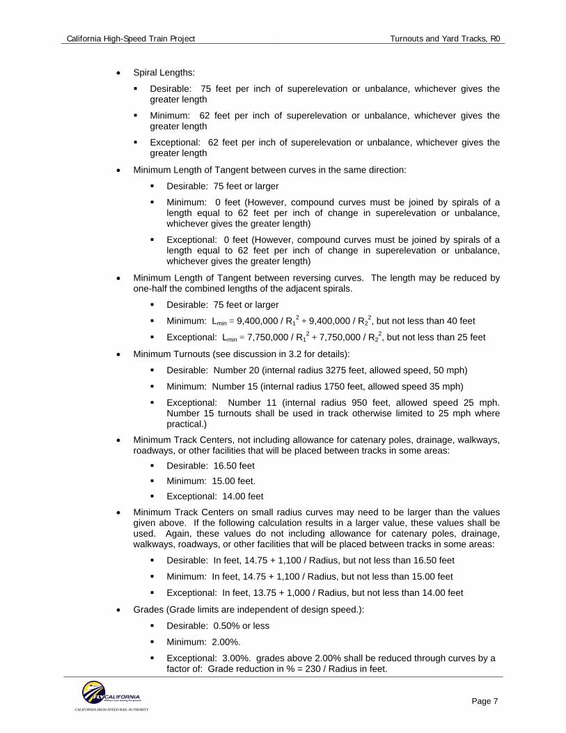
• Spiral Lengths:
Desirable: 75 feet per inch of superelevation or unbalance, whichever gives the greater length
Minimum: 62 feet per inch of superelevation or unbalance, whichever gives the greater length
Exceptional: 62 feet per inch of superelevation or unbalance, whichever gives the greater length
• Minimum Length of Tangent between curves in the same direction:
Desirable: 75 feet or larger
Minimum: 0 feet (However, compound curves must be joined by spirals of a length equal to 62 feet per inch of change in superelevation or unbalance, whichever gives the greater length)
Exceptional: 0 feet (However, compound curves must be joined by spirals of a length equal to 62 feet per inch of change in superelevation or unbalance, whichever gives the greater length)
• Minimum Length of Tangent between reversing curves. The length may be reduced by one-half the combined lengths of the adjacent spirals.
Desirable: 75 feet or larger
Minimum: Lmin = 9,400,000 / R12 + 9,400,000 / R2
2, but not less than 40 feet
Exceptional: Lmin = 7,750,000 / R12 + 7,750,000 / R2
2, but not less than 25 feet
• Minimum Turnouts (see discussion in 3.2 for details):
Desirable: Number 20 (internal radius 3275 feet, allowed speed, 50 mph)
Minimum: Number 15 (internal radius 1750 feet, allowed speed 35 mph)
Exceptional: Number 11 (internal radius 950 feet, allowed speed 25 mph. Number 15 turnouts shall be used in track otherwise limited to 25 mph where practical.)
• Minimum Track Centers, not including allowance for catenary poles, drainage, walkways, roadways, or other facilities that will be placed between tracks in some areas:
Desirable: 16.50 feet Minimum: 15.00 feet. Exceptional: 14.00 feet
• Minimum Track Centers on small radius curves may need to be larger than the values given above. If the following calculation results in a larger value, these values shall be used. Again, these values do not including allowance for catenary poles, drainage, walkways, roadways, or other facilities that will be placed between tracks in some areas:
Desirable: In feet, 14.75 + 1,100 / Radius, but not less than 16.50 feet
Minimum: In feet, 14.75 + 1,100 / Radius, but not less than 15.00 feet
Exceptional: In feet, 13.75 + 1,000 / Radius, but not less than 14.00 feet
• Grades (Grade limits are independent of design speed.):
Desirable: 0.50% or less
Minimum: 2.00%.
Exceptional: 3.00%. grades above 2.00% shall be reduced through curves by a factor of: Grade reduction in % = 230 / Radius in feet.
California High-Speed Train Project Turnouts and Yard Tracks, R0
CALIFORNIA HIGH-SPEED RAIL AUTHORITY
Page 8
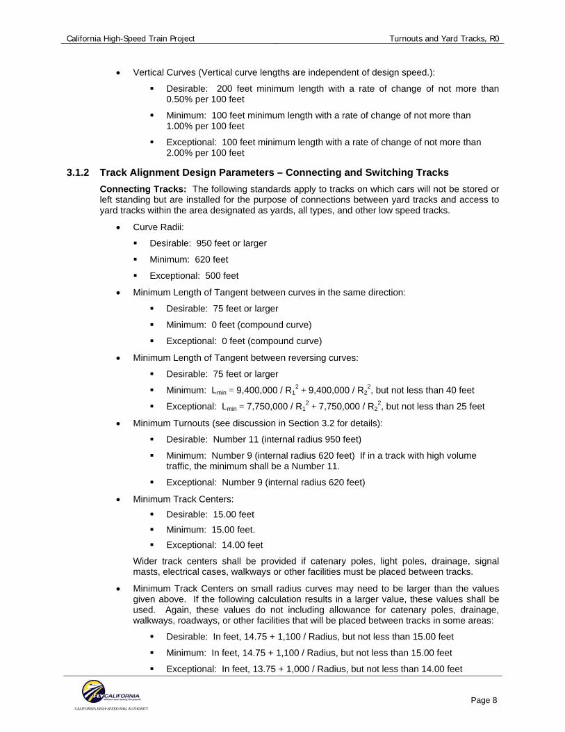
• Vertical Curves (Vertical curve lengths are independent of design speed.):
Desirable: 200 feet minimum length with a rate of change of not more than 0.50% per 100 feet
Minimum: 100 feet minimum length with a rate of change of not more than 1.00% per 100 feet
Exceptional: 100 feet minimum length with a rate of change of not more than 2.00% per 100 feet
3.1.2 Track Alignment Design Parameters – Connecting and Switching Tracks Connecting Tracks: The following standards apply to tracks on which cars will not be stored or left standing but are installed for the purpose of connections between yard tracks and access to yard tracks within the area designated as yards, all types, and other low speed tracks.
• Curve Radii:
Desirable: 950 feet or larger
Minimum: 620 feet
Exceptional: 500 feet
• Minimum Length of Tangent between curves in the same direction:
Desirable: 75 feet or larger
Minimum: 0 feet (compound curve)
Exceptional: 0 feet (compound curve)
• Minimum Length of Tangent between reversing curves:
Desirable: 75 feet or larger
Minimum: Lmin = 9,400,000 / R12 + 9,400,000 / R2
2, but not less than 40 feet
Exceptional: Lmin = 7,750,000 / R12 + 7,750,000 / R2
2, but not less than 25 feet
• Minimum Turnouts (see discussion in Section 3.2 for details):
Desirable: Number 11 (internal radius 950 feet)
Minimum: Number 9 (internal radius 620 feet) If in a track with high volume traffic, the minimum shall be a Number 11.
Exceptional: Number 9 (internal radius 620 feet)
• Minimum Track Centers: Desirable: 15.00 feet Minimum: 15.00 feet. Exceptional: 14.00 feet
Wider track centers shall be provided if catenary poles, light poles, drainage, signal masts, electrical cases, walkways or other facilities must be placed between tracks.
• Minimum Track Centers on small radius curves may need to be larger than the values given above. If the following calculation results in a larger value, these values shall be used. Again, these values do not including allowance for catenary poles, drainage, walkways, roadways, or other facilities that will be placed between tracks in some areas:
Desirable: In feet, 14.75 + 1,100 / Radius, but not less than 15.00 feet
Minimum: In feet, 14.75 + 1,100 / Radius, but not less than 15.00 feet
Exceptional: In feet, 13.75 + 1,000 / Radius, but not less than 14.00 feet
California High-Speed Train Project Turnouts and Yard Tracks, R0
CALIFORNIA HIGH-SPEED RAIL AUTHORITY
Page 9
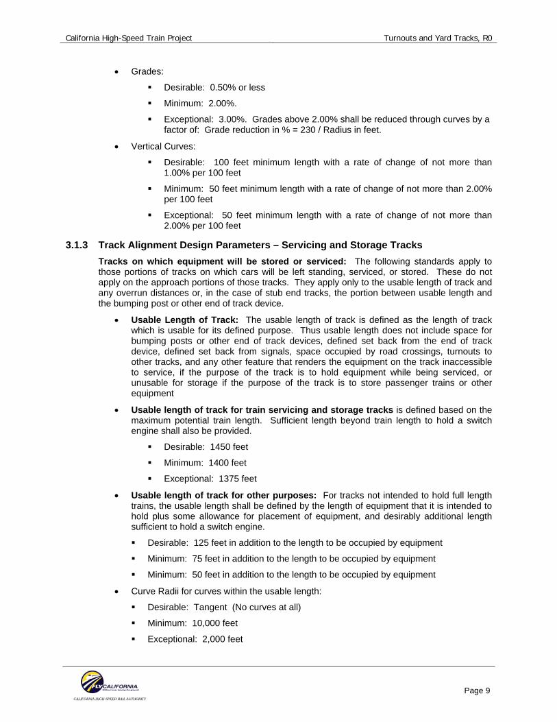
• Grades:
Desirable: 0.50% or less
Minimum: 2.00%.
Exceptional: 3.00%. Grades above 2.00% shall be reduced through curves by a factor of: Grade reduction in % = 230 / Radius in feet.
• Vertical Curves:
Desirable: 100 feet minimum length with a rate of change of not more than 1.00% per 100 feet
Minimum: 50 feet minimum length with a rate of change of not more than 2.00% per 100 feet
Exceptional: 50 feet minimum length with a rate of change of not more than 2.00% per 100 feet
3.1.3 Track Alignment Design Parameters – Servicing and Storage Tracks Tracks on which equipment will be stored or serviced: The following standards apply to those portions of tracks on which cars will be left standing, serviced, or stored. These do not apply on the approach portions of those tracks. They apply only to the usable length of track and any overrun distances or, in the case of stub end tracks, the portion between usable length and the bumping post or other end of track device.
• Usable Length of Track: The usable length of track is defined as the length of track which is usable for its defined purpose. Thus usable length does not include space for bumping posts or other end of track devices, defined set back from the end of track device, defined set back from signals, space occupied by road crossings, turnouts to other tracks, and any other feature that renders the equipment on the track inaccessible to service, if the purpose of the track is to hold equipment while being serviced, or unusable for storage if the purpose of the track is to store passenger trains or other equipment
• Usable length of track for train servicing and storage tracks is defined based on the maximum potential train length. Sufficient length beyond train length to hold a switch engine shall also be provided.
Desirable: 1450 feet
Minimum: 1400 feet
Exceptional: 1375 feet
• Usable length of track for other purposes: For tracks not intended to hold full length trains, the usable length shall be defined by the length of equipment that it is intended to hold plus some allowance for placement of equipment, and desirably additional length sufficient to hold a switch engine.
Desirable: 125 feet in addition to the length to be occupied by equipment
Minimum: 75 feet in addition to the length to be occupied by equipment
Minimum: 50 feet in addition to the length to be occupied by equipment
• Curve Radii for curves within the usable length:
Desirable: Tangent (No curves at all)
Minimum: 10,000 feet
Exceptional: 2,000 feet
California High-Speed Train Project Turnouts and Yard Tracks, R0
CALIFORNIA HIGH-SPEED RAIL AUTHORITY
Page 10
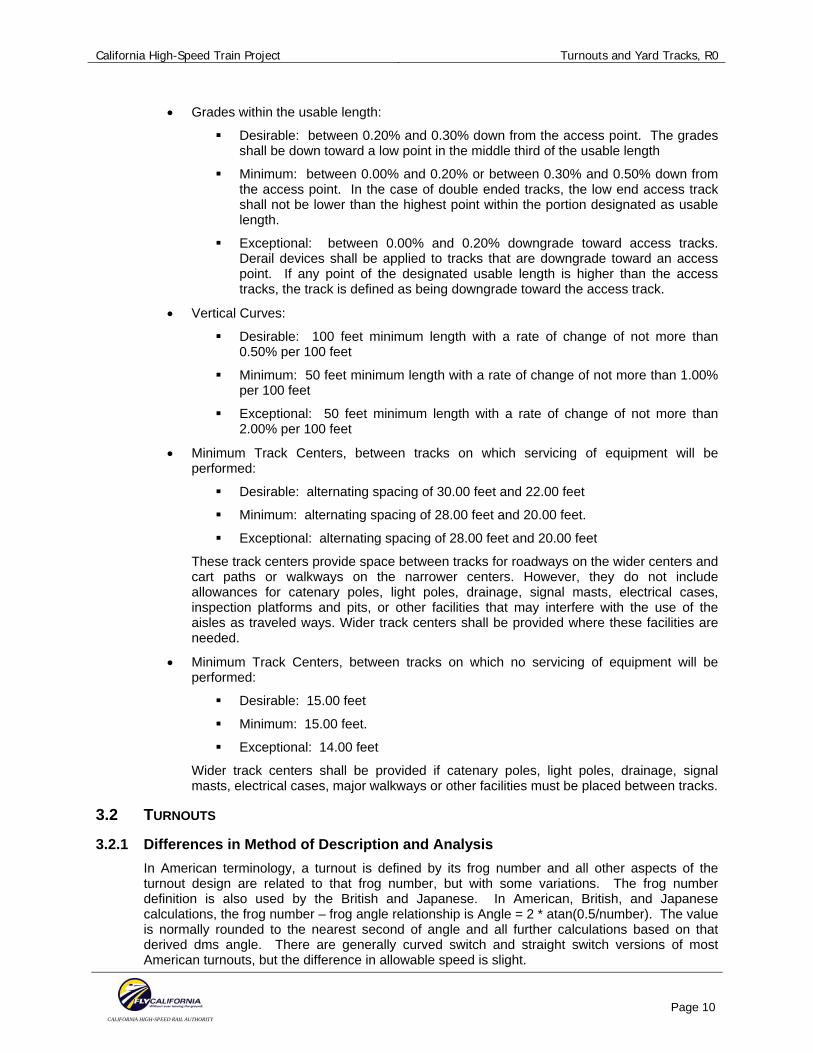
• Grades within the usable length:
Desirable: between 0.20% and 0.30% down from the access point. The grades shall be down toward a low point in the middle third of the usable length
Minimum: between 0.00% and 0.20% or between 0.30% and 0.50% down from the access point. In the case of double ended tracks, the low end access track shall not be lower than the highest point within the portion designated as usable length.
Exceptional: between 0.00% and 0.20% downgrade toward access tracks. Derail devices shall be applied to tracks that are downgrade toward an access point. If any point of the designated usable length is higher than the access tracks, the track is defined as being downgrade toward the access track.
• Vertical Curves:
Desirable: 100 feet minimum length with a rate of change of not more than 0.50% per 100 feet
Minimum: 50 feet minimum length with a rate of change of not more than 1.00% per 100 feet
Exceptional: 50 feet minimum length with a rate of change of not more than 2.00% per 100 feet
• Minimum Track Centers, between tracks on which servicing of equipment will be performed:
Desirable: alternating spacing of 30.00 feet and 22.00 feet
Minimum: alternating spacing of 28.00 feet and 20.00 feet.
Exceptional: alternating spacing of 28.00 feet and 20.00 feet
These track centers provide space between tracks for roadways on the wider centers and cart paths or walkways on the narrower centers. However, they do not include allowances for catenary poles, light poles, drainage, signal masts, electrical cases, inspection platforms and pits, or other facilities that may interfere with the use of the aisles as traveled ways. Wider track centers shall be provided where these facilities are needed.
• Minimum Track Centers, between tracks on which no servicing of equipment will be performed:
Desirable: 15.00 feet
Minimum: 15.00 feet.
Exceptional: 14.00 feet
Wider track centers shall be provided if catenary poles, light poles, drainage, signal masts, electrical cases, major walkways or other facilities must be placed between tracks.
3.2 TURNOUTS
3.2.1 Differences in Method of Description and Analysis In American terminology, a turnout is defined by its frog number and all other aspects of the turnout design are related to that frog number, but with some variations. The frog number definition is also used by the British and Japanese. In American, British, and Japanese calculations, the frog number – frog angle relationship is Angle = 2 * atan(0.5/number). The value is normally rounded to the nearest second of angle and all further calculations based on that derived dms angle. There are generally curved switch and straight switch versions of most American turnouts, but the difference in allowable speed is slight.
California High-Speed Train Project Turnouts and Yard Tracks, R0
CALIFORNIA HIGH-SPEED RAIL AUTHORITY
Page 11
In European calculations the radius is defined and all values calculated from that radius. The frog may be either straight or curved. Therefore quite frequently there will be two and sometimes more angles for a single defined radius, or multiple and significantly different radii for the same angle. In European calculations the frog number – frog angle relationship is Number = 1/tan(angle), and is normally written as the ratio 1:N. For curved frogs, the location at which this angle is measured and the “N” determined is not the point, but the angle between the ends of the rails on the heel end of the frog. Examples that may be seen in European turnout lists are such things as a 190-1:9 and a 300-1:9. In the 190-1:9, the curve radius is 190 meters and the curve ends short of the frog. The frog is straight with a 1:9 ratio, angle 6d 20m 25s. In the 300-1:9, the curve radius is 300 meters and carries completely through the frog. The 1:9 ratio is defined as being at the end of the heel of the frog. At the point (nose) of the frog, the angle is 5d 35m 59s, a No. 10.22 in American terminology. For the same 300 meter radius there is also a straight frog version, commonly at a ratio of 1:12, angle 4d 45m 49s, which is called a 300-1:12.
The beginning point of an American turnout is the actual point of switch. In European turnouts, the beginning point is defined as the theoretical beginning point of the curve through the turnout. The actual point of switch is cut back a short distance beyond that point.
The point of frog as defined in American turnouts is referred to as the ½ inch point of frog. It is not at the location where the gauge lines of the rails actually meet. It is defined variously as the point where the gauge lines are ½ inch apart or as one-half the distance in inches from the theoretical point of the frog. The point of frog as defined in European terminology and calculations is the theoretical point of intersection of the gauge lines of the rails.
3.2.2 Turnout Geometry For development of the specific turnout geometry, see Technical Memorandum 2.1.3, Turnouts and Station tracks.
The yard turnouts and other low and medium speed turnouts will use straight frogs having the same standard frog numbers as the current BNSF/UPRR standards so as to both reduce costs and simplify future maintenance and procurement of replacement parts. The standard AREMA style switch point geometry will not be used due to its high entry angle which could result in the possibility of point climb due to the nature of the suspension of most high-speed trainsets. Instead, the internal curve will be of a “tangent point” design so as to give a small switch point entry angle.
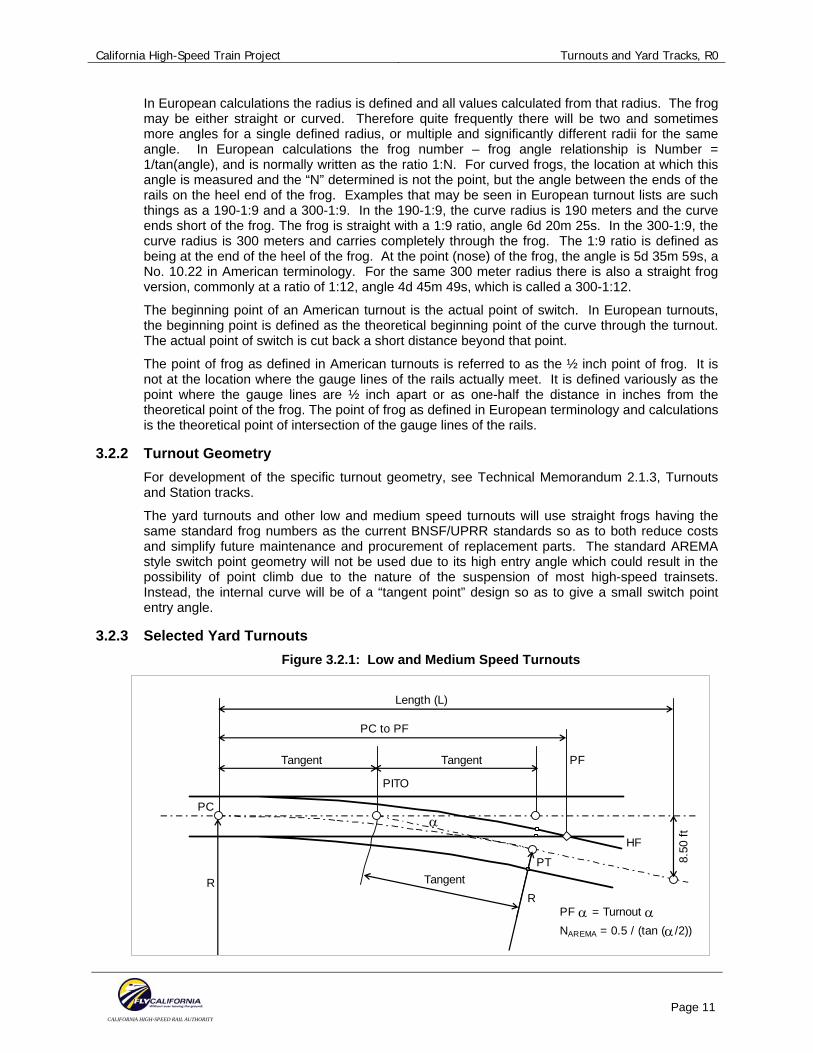
3.2.3 Selected Yard Turnouts Figure 3.2.1: Low and Medium Speed Turnouts
Length (L)
PC to PF
PC
HF
Tangent
PT
R
Tangent
Tangent
PF α = Turnout α NAREMA = 0.5 / (tan (α/2))
PF
PITO
α
R
8.50
ft
California High-Speed Train Project Turnouts and Yard Tracks, R0
CALIFORNIA HIGH-SPEED RAIL AUTHORITY
Page 12
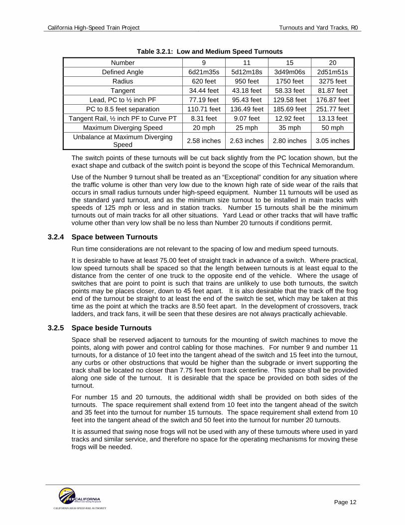
Table 3.2.1: Low and Medium Speed Turnouts Number 9 11 15 20
Defined Angle 6d21m35s 5d12m18s 3d49m06s 2d51m51s Radius 620 feet 950 feet 1750 feet 3275 feet Tangent 34.44 feet 43.18 feet 58.33 feet 81.87 feet
Lead, PC to ½ inch PF 77.19 feet 95.43 feet 129.58 feet 176.87 feet PC to 8.5 feet separation 110.71 feet 136.49 feet 185.69 feet 251.77 feet
Tangent Rail, ½ inch PF to Curve PT 8.31 feet 9.07 feet 12.92 feet 13.13 feet Maximum Diverging Speed 20 mph 25 mph 35 mph 50 mph
Unbalance at Maximum Diverging Speed 2.58 inches 2.63 inches 2.80 inches 3.05 inches
The switch points of these turnouts will be cut back slightly from the PC location shown, but the exact shape and cutback of the switch point is beyond the scope of this Technical Memorandum.
Use of the Number 9 turnout shall be treated as an “Exceptional” condition for any situation where the traffic volume is other than very low due to the known high rate of side wear of the rails that occurs in small radius turnouts under high-speed equipment. Number 11 turnouts will be used as the standard yard turnout, and as the minimum size turnout to be installed in main tracks with speeds of 125 mph or less and in station tracks. Number 15 turnouts shall be the minimum turnouts out of main tracks for all other situations. Yard Lead or other tracks that will have traffic volume other than very low shall be no less than Number 20 turnouts if conditions permit.
3.2.4 Space between Turnouts Run time considerations are not relevant to the spacing of low and medium speed turnouts.
It is desirable to have at least 75.00 feet of straight track in advance of a switch. Where practical, low speed turnouts shall be spaced so that the length between turnouts is at least equal to the distance from the center of one truck to the opposite end of the vehicle. Where the usage of switches that are point to point is such that trains are unlikely to use both turnouts, the switch points may be places closer, down to 45 feet apart. It is also desirable that the track off the frog end of the turnout be straight to at least the end of the switch tie set, which may be taken at this time as the point at which the tracks are 8.50 feet apart. In the development of crossovers, track ladders, and track fans, it will be seen that these desires are not always practically achievable.
3.2.5 Space beside Turnouts Space shall be reserved adjacent to turnouts for the mounting of switch machines to move the points, along with power and control cabling for those machines. For number 9 and number 11 turnouts, for a distance of 10 feet into the tangent ahead of the switch and 15 feet into the turnout, any curbs or other obstructions that would be higher than the subgrade or invert supporting the track shall be located no closer than 7.75 feet from track centerline. This space shall be provided along one side of the turnout. It is desirable that the space be provided on both sides of the turnout.
For number 15 and 20 turnouts, the additional width shall be provided on both sides of the turnouts. The space requirement shall extend from 10 feet into the tangent ahead of the switch and 35 feet into the turnout for number 15 turnouts. The space requirement shall extend from 10 feet into the tangent ahead of the switch and 50 feet into the turnout for number 20 turnouts.
It is assumed that swing nose frogs will not be used with any of these turnouts where used in yard tracks and similar service, and therefore no space for the operating mechanisms for moving these frogs will be needed.
California High-Speed Train Project Turnouts and Yard Tracks, R0
CALIFORNIA HIGH-SPEED RAIL AUTHORITY
Page 13
3.3 CROSSOVERS
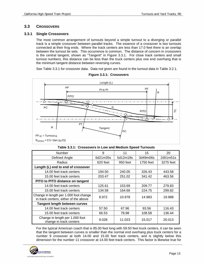
3.3.1 Single Crossovers The most common arrangement of turnouts beyond a simple turnout to a diverging or parallel track is a simple crossover between parallel tracks. The essence of a crossover is two turnouts connected at their frog ends. Where the track centers are less than 17.0 feet there is an overlap between the turnout tie sets. This occurrence is common. The distance of concern in crossovers is the central tangent, shown as “Tangent” in Figure 3.3.1. For close track centers and small turnout numbers, this distance can be less than the truck centers plus one end overhang that is the minimum tangent distance between reversing curves.
See Table 3.3.1 for crossover data. Data not given are found in the turnout data in Table 3.2.1.
Figure 3.3.1: Crossovers
Length (L)
PI to PI
PC
HF
PTR Tangent
PF α = Turnout α NAREMA = 0.5 / (tan (α/2))
PF
PITO
α
R
TC
PC
PITO
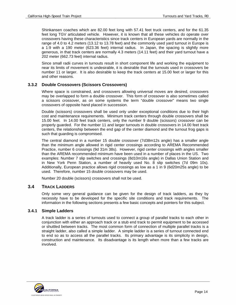
Table 3.3.1: Crossovers in Low and Medium Speed Turnouts
Number 9 11 15 20 Defined Angle 6d21m35s 5d12m18s 3d49m06s 2d51m51s
Radius 620 feet 950 feet 1750 feet 3275 feet Length (L) end to end of crossover
14.00 feet track centers 194.50 240.05 326.43 443.58 15.00 feet track centers 203.47 251.02 341.42 463.56
PITO to PITO distance on tangent 14.00 feet track centers 125.61 153.69 209.77 279.83 15.00 feet track centers 134.58 164.66 224.75 299.82
Change in length per 1.000 foot change in track centers, either of the above 8.972 10.978 14.983 19.988
Tangent length between curves 14.00 feet track centers 57.50 67.96 93.56 116.43 15.00 feet track centers 66.53 78.98 108.58 136.44
Change in length per 1.000 foot change in track centers 9.028 11.023 15.017 20.013
For the typical American coach that is 85.00 feet long with 59.50 feet truck centers, it can be seen that the tangent between curves is smaller than the normal end overhang plus truck centers for a number 9 crossover at both 14.00 and 15.00 feet track centers, and is slightly below this dimension for the number 11 crossover at 14.00 feet track centers. This factor is likewise true for
California High-Speed Train Project Turnouts and Yard Tracks, R0
CALIFORNIA HIGH-SPEED RAIL AUTHORITY
Page 14
Shinkansen coaches which are 82.00 feet long with 57.41 feet truck centers, and for the 61.35 feet long TGV articulated vehicle. However, it is known that all these vehicles do operate over crossovers having these characteristics since track centers in European yards are normally in the range of 4.0 to 4.2 meters (13.12 to 13.78 feet) and the commonly used yard turnout in Europe is a 1:9 with a 190 meter (623.36 feet) internal radius. In Japan, the spacing is slightly more generous, in that track centers are normally 4.3 meters (14.11 feet) and their yard turnout have a 202 meter (662.73 feet) internal radius.
Since small radii curves in turnouts result in short component life and working the equipment to near its limits of movement is undesirable, it is desirable that the turnouts used in crossovers be number 11 or larger. It is also desirable to keep the track centers at 15.00 feet or larger for this and other reasons.
3.3.2 Double Crossovers (Scissors Crossovers) Where space is constrained, and crossovers allowing universal moves are desired, crossovers may be overlapped to form a double crossover. This form of crossover is also sometimes called a scissors crossover, as on some systems the term “double crossover” means two single crossovers of opposite hand placed in succession.
Double (scissors) crossovers shall be used only under exceptional conditions due to their high cost and maintenance requirements. Minimum track centers through double crossovers shall be 15.00 feet. In 14.00 feet track centers, only the number 9 double (scissors) crossover can be properly guarded. For the number 11 and larger turnouts in double crossovers in 14.00 feet track centers, the relationship between the end gap of the center diamond and the turnout frog gaps is such that guarding is compromised.
The central diamond in a number 15 double crossover (7d38m12s angle) has a smaller angle than the minimum angle allowed in rigid center crossings according to AREMA Recommended Practice, number 6 crossings (9d 31m 38s). However, rigid center crossings with angles smaller than the AREMA recommended minimum have been used in a number of places in the US. Two examples: Number 7 slip switches and crossings (8d10m16s angle) in Dallas Union Station and in New York Penn Station, a number of heavily used No. 8 slip switches (7d 09m 10s). Additionally, European practice allows rigid crossings as low as a 1 in 9 (6d20m25s angle) to be used. Therefore, number 15 double crossovers may be used.
Number 20 double (scissors) crossovers shall not be used.
3.4 TRACK LADDERS Only some very general guidance can be given for the design of track ladders, as they by necessity have to be developed for the specific site conditions and track requirements. The information in the following sections presents a few basic concepts and pointers for this subject.
3.4.1 Simple Ladders A track ladder is a series of turnouts used to connect a group of parallel tracks to each other in conjunction with either an approach track or a stub end track to permit equipment to be accessed or shuttled between tracks. The most common form of connection of multiple parallel tracks is a straight ladder, also called a simple ladder. A simple ladder is a series of turnout connected end to end so as to access all the parallel tracks. Its primary advantage is its simplicity in design, construction and maintenance. Its disadvantage is its length when more than a few tracks are involved.
California High-Speed Train Project Turnouts and Yard Tracks, R0
CALIFORNIA HIGH-SPEED RAIL AUTHORITY
Page 15
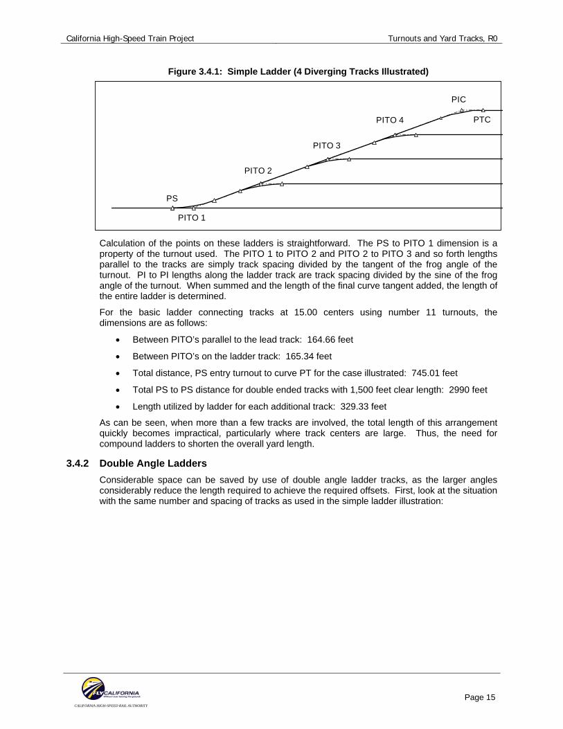
Figure 3.4.1: Simple Ladder (4 Diverging Tracks Illustrated)
PITO 1
PITO 2
PITO 3
PITO 4
PIC
PTC
PS
Calculation of the points on these ladders is straightforward. The PS to PITO 1 dimension is a property of the turnout used. The PITO 1 to PITO 2 and PITO 2 to PITO 3 and so forth lengths parallel to the tracks are simply track spacing divided by the tangent of the frog angle of the turnout. PI to PI lengths along the ladder track are track spacing divided by the sine of the frog angle of the turnout. When summed and the length of the final curve tangent added, the length of the entire ladder is determined.
For the basic ladder connecting tracks at 15.00 centers using number 11 turnouts, the dimensions are as follows:
• Between PITO’s parallel to the lead track: 164.66 feet
• Between PITO’s on the ladder track: 165.34 feet
• Total distance, PS entry turnout to curve PT for the case illustrated: 745.01 feet
• Total PS to PS distance for double ended tracks with 1,500 feet clear length: 2990 feet
• Length utilized by ladder for each additional track: 329.33 feet
As can be seen, when more than a few tracks are involved, the total length of this arrangement quickly becomes impractical, particularly where track centers are large. Thus, the need for compound ladders to shorten the overall yard length.
3.4.2 Double Angle Ladders Considerable space can be saved by use of double angle ladder tracks, as the larger angles considerably reduce the length required to achieve the required offsets. First, look at the situation with the same number and spacing of tracks as used in the simple ladder illustration:
California High-Speed Train Project Turnouts and Yard Tracks, R0
CALIFORNIA HIGH-SPEED RAIL AUTHORITY
Page 16
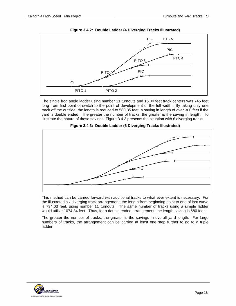
Figure 3.4.2: Double Ladder (4 Diverging Tracks Illustrated)
PIC PTC 5
PITO 4
PITO 3
PIC
PTC 4
PIC
PITO 2PITO 1
PS
The single frog angle ladder using number 11 turnouts and 15.00 feet track centers was 745 feet long from first point of switch to the point of development of the full width. By taking only one track off the outside, the length is reduced to 580.35 feet, a saving in length of over 300 feet if the yard is double ended. The greater the number of tracks, the greater is the saving in length. To illustrate the nature of these savings, Figure 3.4.3 presents the situation with 6 diverging tracks.
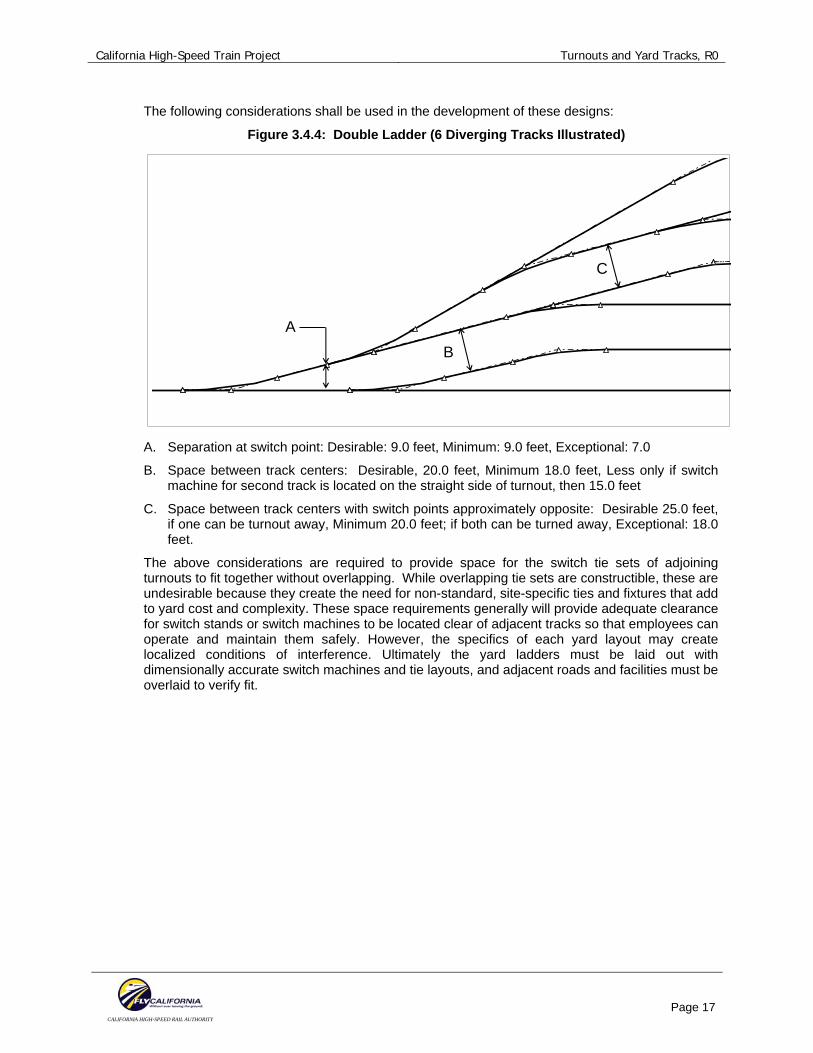
Figure 3.4.3: Double Ladder (6 Diverging Tracks Illustrated)
This method can be carried forward with additional tracks to what ever extent is necessary. For the illustrated six diverging track arrangement, the length from beginning point to end of last curve is 734.03 feet, using number 11 turnouts. The same number of tracks using a simple ladder would utilize 1074.34 feet. Thus, for a double ended arrangement, the length saving is 680 feet.
The greater the number of tracks, the greater is the savings in overall yard length. For large numbers of tracks, the arrangement can be carried at least one step further to go to a triple ladder.
California High-Speed Train Project Turnouts and Yard Tracks, R0
CALIFORNIA HIGH-SPEED RAIL AUTHORITY
Page 17
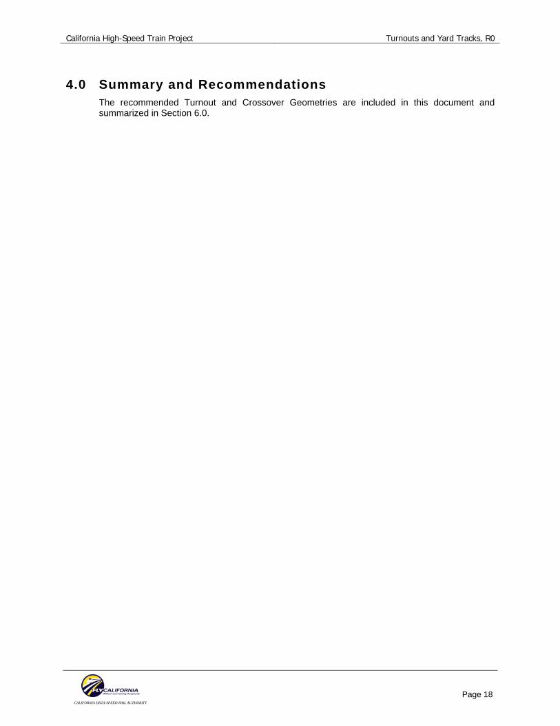
The following considerations shall be used in the development of these designs:
Figure 3.4.4: Double Ladder (6 Diverging Tracks Illustrated)
AB
C
A. Separation at switch point: Desirable: 9.0 feet, Minimum: 9.0 feet, Exceptional: 7.0
B. Space between track centers: Desirable, 20.0 feet, Minimum 18.0 feet, Less only if switch machine for second track is located on the straight side of turnout, then 15.0 feet
C. Space between track centers with switch points approximately opposite: Desirable 25.0 feet, if one can be turnout away, Minimum 20.0 feet; if both can be turned away, Exceptional: 18.0 feet.
The above considerations are required to provide space for the switch tie sets of adjoining turnouts to fit together without overlapping. While overlapping tie sets are constructible, these are undesirable because they create the need for non-standard, site-specific ties and fixtures that add to yard cost and complexity. These space requirements generally will provide adequate clearance for switch stands or switch machines to be located clear of adjacent tracks so that employees can operate and maintain them safely. However, the specifics of each yard layout may create localized conditions of interference. Ultimately the yard ladders must be laid out with dimensionally accurate switch machines and tie layouts, and adjacent roads and facilities must be overlaid to verify fit.
California High-Speed Train Project Turnouts and Yard Tracks, R0
CALIFORNIA HIGH-SPEED RAIL AUTHORITY
Page 18
4.0 Summary and Recommendations The recommended Turnout and Crossover Geometries are included in this document and summarized in Section 6.0.
California High-Speed Train Project Turnouts and Yard Tracks, R0
CALIFORNIA HIGH-SPEED RAIL AUTHORITY
Page 19
5.0 SOURCE INFORMATION AND REFERENCES 1. Manual for Railway Engineering of the American Railway Engineering and Maintenance of
Way Association (AREMA Manual) and the AREMA Portfolio of Trackwork Plans.
2. Track Standard Drawings: Union Pacific Railroad, 2005
California High-Speed Train Project Turnouts and Yard Tracks, R0
CALIFORNIA HIGH-SPEED RAIL AUTHORITY
Page 20
6.0 DESIGN MANUAL CRITERIA 6.1 YARD ACCESS TRACKS; YARD, STORAGE, AND OTHER LOW SPEED TRACKS
The specific track arrangement for each yard will depend upon the purpose of the yard and tracks in the yard. Therefore the basic layout will be determined by operational requirements. The requirements developed in this Technical Memorandum are therefore limited to those of a general nature except for those relating to geometric constraints due to
• Curvature related constraints due to vehicle characteristics
• Track length constraints due to train and individual vehicle length
• Profile and grade related issues
Other than the tracks connecting the yards to the revenue tracks, the design parameters for these tracks are speed-independent.
6.1.1 Track Alignment Design Parameters – Access and Main Line Connecting Tracks Main Line Connecting Tracks: Site constraints may lead to large distances between main line access points and yards. For the purpose of minimizing time into and out of yards, and minimizing the time required to clear revenue tracks, the tracks connecting main lines to yard shall be designed to higher speed standards than the yard itself. These tracks shall therefore be designed much like a secondary main line railroad.
Since speed of trains on these tracks is likely to be highly variable, including the likelihood that trains may frequently be stopped on these tracks, superelevation shall be kept to low values to the greatest extent practical.
• Minimum Radius:
Desirable: 2,500 feet
Minimum: 900 feet
Exceptional: 500 feet
• Design Speed:
Desirable: 50 mph
Minimum: 35 mph
Exceptional: 25 mph
• Curve Radii shall be based on the allowed superelevation and unbalance for the selected speed based on the following limits for superelevation and unbalanced superelevation:
• Superelevation
Desirable: 2 inches or less
Minimum: 3 inches
Exceptional: 3 inches
• Unbalanced Superelevation
Desirable: 2 inches or less
Minimum: 3 inches
Exceptional: 3 inches

California High-Speed Train Project Turnouts and Yard Tracks, R0
CALIFORNIA HIGH-SPEED RAIL AUTHORITY
Page 21
• Spiral Lengths:
Desirable: 75 feet per inch of superelevation or unbalance, whichever gives the greatest length
Minimum: 62 feet per inch of superelevation or unbalance, whichever gives the greatest length
Exceptional: 62 feet per inch of superelevation or unbalance, whichever gives the greatest length
• Minimum Length of Tangent between curves in the same direction:
Desirable: 75 feet or larger
Minimum: 0 feet (However, compound curves must be joined by spirals of a length equal to 62 feet per inch of change in superelevation or unbalance, whichever gives the greater length)
Exceptional: 0 feet (However, compound curves must be joined by spirals of a length equal to 62 feet per inch of change in superelevation or unbalance, whichever gives the greater length)
• Minimum Length of Tangent between reversing curves. The length may be reduced by one-half the combined lengths of the adjacent spirals.
Desirable: 75 feet or larger
Minimum: Lmin = 9,400,000 / R12 + 9,400,000 / R2
2, but not less than 40 feet
Exceptional: Lmin = 7,750,000 / R12 + 7,750,000 / R2
2, but not less than 25 feet
• Minimum Turnouts (see discussion in 6.2 for details):
Desirable: Number 20 (internal radius 3275 feet, allowed speed, 50 mph)
Minimum: Number 15 (internal radius 1750 feet, allowed speed 35 mph)
Exceptional: Number 11 (internal radius 950 feet, allowed speed 25 mph. Number 15 turnouts shall be used in track otherwise limited to 25 mph where practical.)
• Minimum Track Centers, not including allowance for catenary poles, drainage, walkways, roadways, or other facilities that will be placed between tracks in some areas:
Desirable: 16.50 feet Minimum: 15.00 feet. Exceptional: 14.00 feet
• Minimum Track Centers on small radius curves may need to be larger than the values given above. If the following calculation results in a larger value, these values shall be used. Again, these values do not including allowance for catenary poles, drainage, walkways, roadways, or other facilities that will be placed between tracks in some areas:
Desirable: In feet, 14.75 + 1,100 / Radius, but not less than 16.50 feet Minimum: In feet, 14.75 + 1,100 / Radius, but not less than 15.00 feet Exceptional: In feet, 13.75 + 1,000 / Radius, but not less than 14.00 feet
• Grades (Grade limits are independent of design speed.):
Desirable: 0.50% or less
Minimum: 2.00%.
Exceptional: 3.00%. grades above 2.00% shall be reduced through curves by a factor of: Grade reduction in % = 230 / Radius in feet.

California High-Speed Train Project Turnouts and Yard Tracks, R0
CALIFORNIA HIGH-SPEED RAIL AUTHORITY
Page 22
• Vertical Curves (Vertical curve lengths are independent of design speed.):
Desirable: 200 feet minimum length with a rate of change of not more than 0.50% per 100 feet
Minimum: 100 feet minimum length with a rate of change of not more than 1.00% per 100 feet
Exceptional: 100 feet minimum length with a rate of change of not more than 2.00% per 100 feet
6.1.2 Track Alignment Design Parameters – Connecting and Switching Tracks Connecting Tracks: The following standards apply to tracks on which cars will not be stored or left standing but are installed for the purpose of connections between yard tracks and access to yard tracks within the area designated as yards, all types, and other low speed tracks.
• Curve Radii:
Desirable: 950 feet or larger
Minimum: 620 feet
Exceptional: 500 feet
• Minimum Length of Tangent between curves in the same direction:
Desirable: 75 feet or larger
Minimum: 0 feet (compound curve)
Exceptional: 0 feet (compound curve)
• Minimum Length of Tangent between reversing curves:
Desirable: 75 feet or larger
Minimum: Lmin = 9,400,000 / R12 + 9,400,000 / R2
2, but not less than 40 feet
Exceptional: Lmin = 7,750,000 / R12 + 7,750,000 / R2
2, but not less than 25 feet
• Minimum Turnouts (see discussion in 6.2 for details):
Desirable: Number 11 (internal radius 950 feet)
Minimum: Number 9 (internal radius 620 feet). If in a track with high volume traffic, the minimum shall be a Number 11.
Exceptional: Number 9 (internal radius 620 feet)
• Minimum Track Centers: Desirable: 15.00 feet Minimum: 15.00 feet. Exceptional: 14.00 feet
Wider track centers shall be provided if catenary poles, light poles, drainage, signal masts, electrical cases, major walkways or other facilities must be placed between tracks.
• Minimum Track Centers on small radius curves may need to be larger than the values given above. If the following calculation results in a larger value, these values shall be used. Again, these values do not including allowance for catenary poles, drainage, walkways, roadways, or other facilities that will be placed between tracks in some areas:
Desirable: In feet, 14.75 + 1,100 / Radius, but not less than 15.00 feet
Minimum: In feet, 14.75 + 1,100 / Radius, but not less than 15.00 feet
Exceptional: In feet, 13.75 + 1,000 / Radius, but not less than 14.00 feet
California High-Speed Train Project Turnouts and Yard Tracks, R0
CALIFORNIA HIGH-SPEED RAIL AUTHORITY
Page 23
• Grades:
Desirable: 0.50% or less
Minimum: 2.00%.
Exceptional: 3.00%. Grades above 2.00% shall be reduced through curves by a factor of: Grade reduction in % = 230 / Radius in feet.
• Vertical Curves:
Desirable: 100 feet minimum length with a rate of change of not more than 1.00% per 100 feet
Minimum: 50 feet minimum length with a rate of change of not more than 2.00% per 100 feet
Exceptional: 50 feet minimum length with a rate of change of not more than 2.00% per 100 feet
6.1.3 Track Alignment Design Parameters – Servicing and Storage Tracks Tracks on which equipment will be stored or serviced: The following standards apply to those portions of tracks on which cars will be left standing, serviced, or stored. They do not apply on the approach portions of those tracks. These apply only to the usable length of track and any overrun distances or, in the case of stub end tracks the portion between usable length and the bumping post or other end of track device.
• Usable Length of Track: The usable length of track is defined as the length of track which is usable for its defined purpose. Thus usable length does not include space for bumping posts or other end of track devices, defined set back from the end of track device, defined set back from signals, space occupied by road crossings, turnouts to other tracks, and any other feature that render the equipment on the track inaccessible to service, if the purpose of the track is to hold equipment while being serviced, or unusable for storage if the purpose of the track is to store passenger trains or other equipment
• Usable length of track for train servicing and storage tracks is defined based on the maximum potential train length. Sufficient length beyond train length to hold a switch engine shall also be provided.
Desirable: 1450 feet
Minimum: 1400 feet
Exceptional: 1375 feet
• Usable length of track for other purposes: For tracks not intended to hold full length trains, the usable length shall be defined by the length of equipment that it is intended to hold plus some allowance for placement of equipment, and desirably additional length sufficient to hold a switch engine.
Desirable: 125 feet in addition to the length to be occupied by equipment
Minimum: 75 feet in addition to the length to be occupied by equipment
Minimum: 50 feet in addition to the length to be occupied by equipment
• Curve Radii for curves within the usable length:
Desirable: Tangent (No curves at all)
Minimum: 10,000 feet
Exceptional: 2,000 feet
California High-Speed Train Project Turnouts and Yard Tracks, R0
CALIFORNIA HIGH-SPEED RAIL AUTHORITY
Page 24
• Grades within the usable length:
Desirable: between 0.20% and 0.30% down from the access point. In the case of double ended tracks, the grades shall be down toward a low point in the middle third of the usable length
Minimum: between 0.00% and 0.20% or between 0.30% and 0.50% down from the access point. In the case of double ended tracks, the low end access track shall not be lower than the highest point within the portion designated as usable length.
Exceptional: between 0.00% and 0.20% downgrade toward access tracks. Derail devices shall be applied to tracks that are downgrade toward an access point. If any point of the designated usable length is higher than the access tracks, the track is defined as being downgrade toward the access track.
• Vertical Curves:
Desirable: 100 feet minimum length with a rate of change of not more than 0.50% per 100 feet
Minimum: 50 feet minimum length with a rate of change of not more than 1.00% per 100 feet
Exceptional: 50 feet minimum length with a rate of change of not more than 2.00% per 100 feet
• Minimum Track Centers, between tracks on which servicing of equipment will be performed:
Desirable: alternating spacing of 30.00 feet and 22.00 feet
Minimum: alternating spacing of 28.00 feet and 20.00 feet.
Exceptional: alternating spacing of 28.00 feet and 20.00 feet
These track centers provide space between tracks for roadways on the wider centers and cart paths or walkways on the narrower centers. However, they do not include allowances for catenary poles, light poles, drainage, signal masts, electrical cases, inspection platforms and pits, or other facilities that may interfere with the use of the aisles as traveled ways. Wider track centers shall be provided where these facilities are needed.
• Minimum Track Centers, between tracks on which no servicing of equipment will be performed:
Desirable: 15.00 feet
Minimum: 15.00 feet.
Exceptional: 14.00 feet
Wider track centers shall be provided if catenary poles, light poles, drainage, signal masts, electrical cases, major walkways or other facilities must be placed between tracks.
6.2 TURNOUT GEOMETRY The yard turnouts and other low and medium speed turnouts will use straight frogs having the same standard frog numbers as the current BNSF/UPRR standards so as to both reduce costs and simplify future maintenance and procurement of replacement parts.
There are certain differences between these turnouts and standard AREMA turnouts. What is not different is the definition of the point of frog. It remains the traditional ½ inch point of frog
The turnouts proposed for this project differ from standard AREMA turnouts in terms of the closure curve and switch geometry. The standard AREMA style switch point geometry is not
California High-Speed Train Project Turnouts and Yard Tracks, R0
CALIFORNIA HIGH-SPEED RAIL AUTHORITY
Page 25
used due to its high entry angle which could result in the possibility that the wheels could climb the switch point due to the nature of the suspension of most high-speed trainsets. Instead, the internal curve will be of a “tangent point” design so as to give a small switch point entry angle. As fabricated, the actual switch point will be cut back slightly from the true PC of the curve, but for geometric calculations this cut back may be ignored.
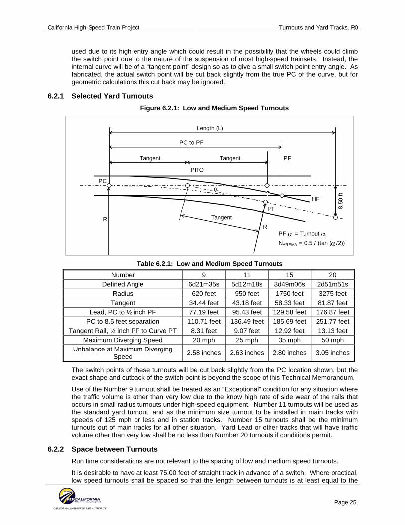
6.2.1 Selected Yard Turnouts Figure 6.2.1: Low and Medium Speed Turnouts
Length (L)
PC to PF
PC
HF
Tangent
PT
R
Tangent
Tangent
PF α = Turnout α NAREMA = 0.5 / (tan (α/2))
PF
PITO
α
R
8.50
ft
Table 6.2.1: Low and Medium Speed Turnouts
Number 9 11 15 20 Defined Angle 6d21m35s 5d12m18s 3d49m06s 2d51m51s
Radius 620 feet 950 feet 1750 feet 3275 feet Tangent 34.44 feet 43.18 feet 58.33 feet 81.87 feet
Lead, PC to ½ inch PF 77.19 feet 95.43 feet 129.58 feet 176.87 feet PC to 8.5 feet separation 110.71 feet 136.49 feet 185.69 feet 251.77 feet
Tangent Rail, ½ inch PF to Curve PT 8.31 feet 9.07 feet 12.92 feet 13.13 feet Maximum Diverging Speed 20 mph 25 mph 35 mph 50 mph
Unbalance at Maximum Diverging Speed 2.58 inches 2.63 inches 2.80 inches 3.05 inches
The switch points of these turnouts will be cut back slightly from the PC location shown, but the exact shape and cutback of the switch point is beyond the scope of this Technical Memorandum.
Use of the Number 9 turnout shall be treated as an “Exceptional” condition for any situation where the traffic volume is other than very low due to the know high rate of side wear of the rails that occurs in small radius turnouts under high-speed equipment. Number 11 turnouts will be used as the standard yard turnout, and as the minimum size turnout to be installed in main tracks with speeds of 125 mph or less and in station tracks. Number 15 turnouts shall be the minimum turnouts out of main tracks for all other situation. Yard Lead or other tracks that will have traffic volume other than very low shall be no less than Number 20 turnouts if conditions permit.
6.2.2 Space between Turnouts Run time considerations are not relevant to the spacing of low and medium speed turnouts.
It is desirable to have at least 75.00 feet of straight track in advance of a switch. Where practical, low speed turnouts shall be spaced so that the length between turnouts is at least equal to the
California High-Speed Train Project Turnouts and Yard Tracks, R0
CALIFORNIA HIGH-SPEED RAIL AUTHORITY
Page 26
distance from the center of one truck to the opposite end of the vehicle. Where the usage of switches that are point to point is such that trains are unlikely to use both turnouts, the switch points may be places closer, down to 45 feet apart. It is also desirable that the track off the frog end of the turnout be straight to at least the end of the switch tie set, which may be taken at this time as the point at which the tracks are 8.50 feet apart. In the development of crossovers, track ladders, and track fans, it will be seen that these desires are not always practically achievable.
6.2.3 Space beside Turnouts Space shall be reserved adjacent to turnouts for the mounting of switch machines to move the points, along with power and control cabling for those machines. For number 9 and number 11 turnouts, a distance of 10 feet into the tangent ahead of the switch and 15 feet into the turnout any curbs or other obstructions that would be higher than the subgrade or invert supporting the track shall be located no closer than 7.75 feet from track centerline. This space shall be provided along one side of the turnout. It is desirable that the space be provided on both sides of the turnout.
For number 15 and 20 turnouts, the additional width shall be provided on both sides of the turnouts. The space requirement shall extend from 10 feet into the tangent ahead of the switch and 35 feet into the turnout for number 15 turnouts. The space requirement shall extend from 10 feet into the tangent ahead of the switch and 50 feet into the turnout for number 20 turnouts.
It is assumed that swing nose frogs will not be used with any of these turnouts where used in yard tracks and similar service, and therefore no space for the operating mechanisms moving these frogs will be needed.
6.3 CROSSOVERS
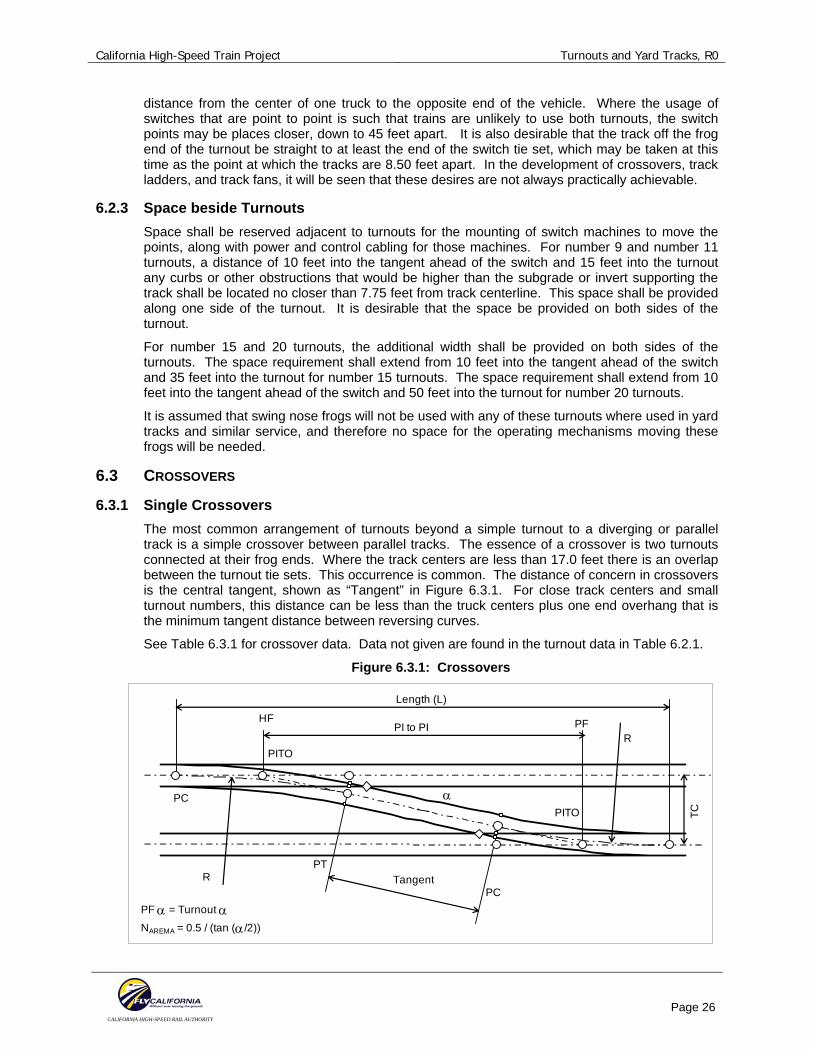
6.3.1 Single Crossovers The most common arrangement of turnouts beyond a simple turnout to a diverging or parallel track is a simple crossover between parallel tracks. The essence of a crossover is two turnouts connected at their frog ends. Where the track centers are less than 17.0 feet there is an overlap between the turnout tie sets. This occurrence is common. The distance of concern in crossovers is the central tangent, shown as “Tangent” in Figure 6.3.1. For close track centers and small turnout numbers, this distance can be less than the truck centers plus one end overhang that is the minimum tangent distance between reversing curves.
See Table 6.3.1 for crossover data. Data not given are found in the turnout data in Table 6.2.1.
Figure 6.3.1: Crossovers
Length (L)
PI to PI
PC
HF
PTR Tangent
PF α = Turnout α NAREMA = 0.5 / (tan (α/2))
PF
PITO
α
R
TC
PC
PITO
California High-Speed Train Project Turnouts and Yard Tracks, R0
CALIFORNIA HIGH-SPEED RAIL AUTHORITY
Page 27
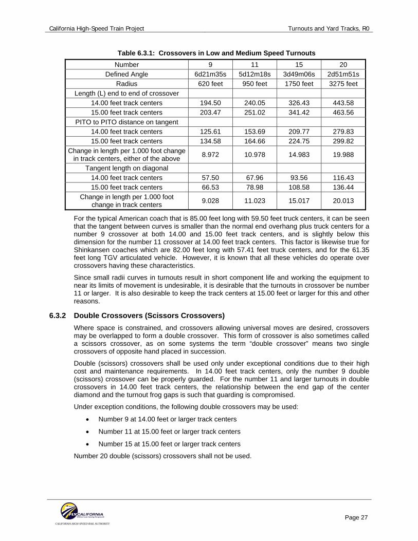
Table 6.3.1: Crossovers in Low and Medium Speed Turnouts Number 9 11 15 20
Defined Angle 6d21m35s 5d12m18s 3d49m06s 2d51m51s Radius 620 feet 950 feet 1750 feet 3275 feet
Length (L) end to end of crossover 14.00 feet track centers 194.50 240.05 326.43 443.58 15.00 feet track centers 203.47 251.02 341.42 463.56
PITO to PITO distance on tangent 14.00 feet track centers 125.61 153.69 209.77 279.83 15.00 feet track centers 134.58 164.66 224.75 299.82
Change in length per 1.000 foot change in track centers, either of the above 8.972 10.978 14.983 19.988
Tangent length on diagonal 14.00 feet track centers 57.50 67.96 93.56 116.43 15.00 feet track centers 66.53 78.98 108.58 136.44
Change in length per 1.000 foot change in track centers 9.028 11.023 15.017 20.013
For the typical American coach that is 85.00 feet long with 59.50 feet truck centers, it can be seen that the tangent between curves is smaller than the normal end overhang plus truck centers for a number 9 crossover at both 14.00 and 15.00 feet track centers, and is slightly below this dimension for the number 11 crossover at 14.00 feet track centers. This factor is likewise true for Shinkansen coaches which are 82.00 feet long with 57.41 feet truck centers, and for the 61.35 feet long TGV articulated vehicle. However, it is known that all these vehicles do operate over crossovers having these characteristics.
Since small radii curves in turnouts result in short component life and working the equipment to near its limits of movement is undesirable, it is desirable that the turnouts in crossover be number 11 or larger. It is also desirable to keep the track centers at 15.00 feet or larger for this and other reasons.
6.3.2 Double Crossovers (Scissors Crossovers) Where space is constrained, and crossovers allowing universal moves are desired, crossovers may be overlapped to form a double crossover. This form of crossover is also sometimes called a scissors crossover, as on some systems the term “double crossover” means two single crossovers of opposite hand placed in succession.
Double (scissors) crossovers shall be used only under exceptional conditions due to their high cost and maintenance requirements. In 14.00 feet track centers, only the number 9 double (scissors) crossover can be properly guarded. For the number 11 and larger turnouts in double crossovers in 14.00 feet track centers, the relationship between the end gap of the center diamond and the turnout frog gaps is such that guarding is compromised.
Under exception conditions, the following double crossovers may be used:
• Number 9 at 14.00 feet or larger track centers
• Number 11 at 15.00 feet or larger track centers
• Number 15 at 15.00 feet or larger track centers
Number 20 double (scissors) crossovers shall not be used.
California High-Speed Train Project Turnouts and Yard Tracks, R0
CALIFORNIA HIGH-SPEED RAIL AUTHORITY
Page 28
6.4 TRACK LADDERS
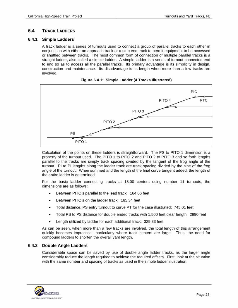
6.4.1 Simple Ladders A track ladder is a series of turnouts used to connect a group of parallel tracks to each other in conjunction with either an approach track or a stub end track to permit equipment to be accessed or shuttled between tracks. The most common form of connection of multiple parallel tracks is a straight ladder, also called a simple ladder. A simple ladder is a series of turnout connected end to end so as to access all the parallel tracks. Its primary advantage is its simplicity in design, construction and maintenance. Its disadvantage is its length when more than a few tracks are involved.
Figure 6.4.1: Simple Ladder (4 Tracks Illustrated)
PITO 1
PITO 2
PITO 3
PITO 4
PIC
PTC
PS
Calculation of the points on these ladders is straightforward. The PS to PITO 1 dimension is a property of the turnout used. The PITO 1 to PITO 2 and PITO 2 to PITO 3 and so forth lengths parallel to the tracks are simply track spacing divided by the tangent of the frog angle of the turnout. PI to PI lengths along the ladder track are track spacing divided by the sine of the frog angle of the turnout. When summed and the length of the final curve tangent added, the length of the entire ladder is determined.
For the basic ladder connecting tracks at 15.00 centers using number 11 turnouts, the dimensions are as follows:
• Between PITO’s parallel to the lead track: 164.66 feet
• Between PITO’s on the ladder track: 165.34 feet
• Total distance, PS entry turnout to curve PT for the case illustrated: 745.01 feet
• Total PS to PS distance for double ended tracks with 1,500 feet clear length: 2990 feet
• Length utilized by ladder for each additional track: 329.33 feet
As can be seen, when more than a few tracks are involved, the total length of this arrangement quickly becomes impractical, particularly where track centers are large. Thus, the need for compound ladders to shorten the overall yard length.
6.4.2 Double Angle Ladders Considerable space can be saved by use of double angle ladder tracks, as the larger angle considerably reduce the length required to achieve the required offsets. First, look at the situation with the same number and spacing of tracks as used in the simple ladder illustration:
California High-Speed Train Project Turnouts and Yard Tracks, R0
CALIFORNIA HIGH-SPEED RAIL AUTHORITY
Page 29
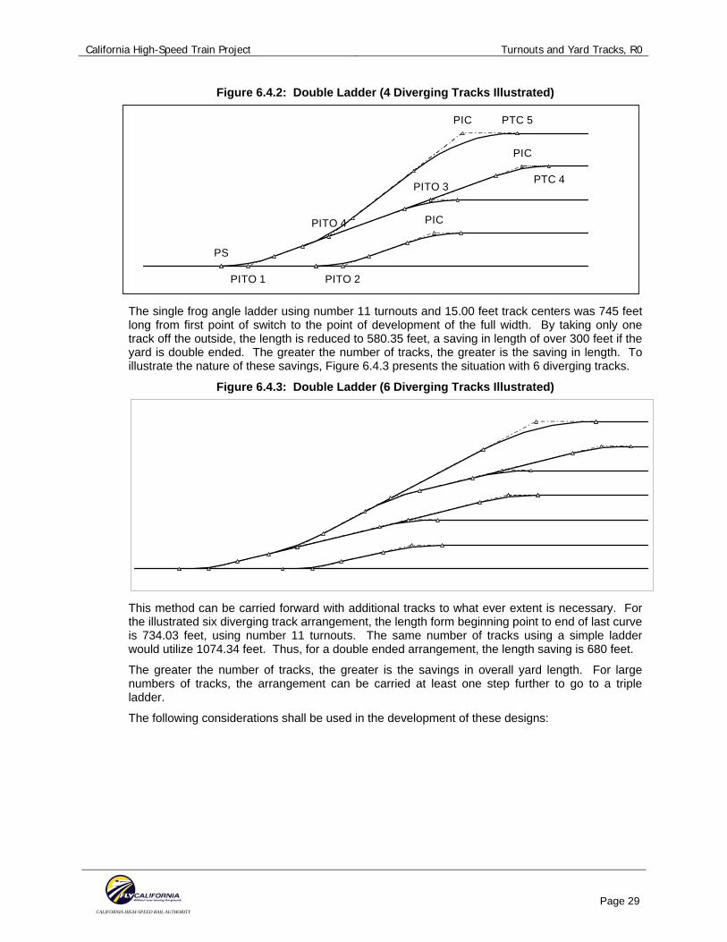
Figure 6.4.2: Double Ladder (4 Diverging Tracks Illustrated)
PIC PTC 5
PITO 4
PITO 3
PIC
PTC 4
PIC
PITO 2PITO 1
PS
The single frog angle ladder using number 11 turnouts and 15.00 feet track centers was 745 feet long from first point of switch to the point of development of the full width. By taking only one track off the outside, the length is reduced to 580.35 feet, a saving in length of over 300 feet if the yard is double ended. The greater the number of tracks, the greater is the saving in length. To illustrate the nature of these savings, Figure 6.4.3 presents the situation with 6 diverging tracks.
Figure 6.4.3: Double Ladder (6 Diverging Tracks Illustrated)
This method can be carried forward with additional tracks to what ever extent is necessary. For the illustrated six diverging track arrangement, the length form beginning point to end of last curve is 734.03 feet, using number 11 turnouts. The same number of tracks using a simple ladder would utilize 1074.34 feet. Thus, for a double ended arrangement, the length saving is 680 feet.
The greater the number of tracks, the greater is the savings in overall yard length. For large numbers of tracks, the arrangement can be carried at least one step further to go to a triple ladder.
The following considerations shall be used in the development of these designs:
California High-Speed Train Project Turnouts and Yard Tracks, R0
CALIFORNIA HIGH-SPEED RAIL AUTHORITY
Page 30
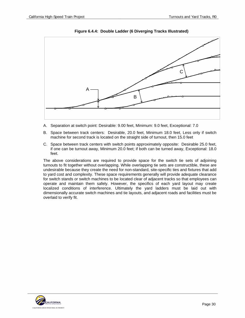
Figure 6.4.4: Double Ladder (6 Diverging Tracks Illustrated)
AB
C
A. Separation at switch point: Desirable: 9.00 feet, Minimum: 9.0 feet, Exceptional: 7.0
B. Space between track centers: Desirable, 20.0 feet, Minimum 18.0 feet, Less only if switch machine for second track is located on the straight side of turnout, then 15.0 feet
C. Space between track centers with switch points approximately opposite: Desirable 25.0 feet, if one can be turnout away, Minimum 20.0 feet; if both can be turned away, Exceptional: 18.0 feet.
The above considerations are required to provide space for the switch tie sets of adjoining turnouts to fit together without overlapping. While overlapping tie sets are constructible, these are undesirable because they create the need for non-standard, site-specific ties and fixtures that add to yard cost and complexity. These space requirements generally will provide adequate clearance for switch stands or switch machines to be located clear of adjacent tracks so that employees can operate and maintain them safely. However, the specifics of each yard layout may create localized conditions of interference. Ultimately the yard ladders must be laid out with dimensionally accurate switch machines and tie layouts, and adjacent roads and facilities must be overlaid to verify fit.