Embed Size (px)
Citation preview
8/7/2019 TM 10-3530-205-10 CLOTHING REPAIR SHOP
http://slidepdf.com/reader/full/tm-10-3530-205-10-clothing-repair-shop 1/455
TM 10-3530-205-14
PAGE
TABLE OF CONTENTS i
EQUIPMENT DESCRIPTION 1-3
OPERATING INSTRUCTIONS 2-1
PMCS - OPERATOR 2-19
LUBRICATION INSTRUCTIONS 3-1
MAINTENANCE INSTRUCTIONS -OPERATOR 3-1
TROUBLESHOOTING -
OPERATOR 3-9
MAINTENANCE INSTRUCTIONSORGANIZATIONAL 5-1
PMCS - ORGANIZATIONAL 5-4
TROUBLESHOOTING -ORGANIZATIONAL 5-23
MAINTENANCE INSTRUCTIONS -
DIRECT SUPPORT 6-1
MAINTENANCE INSTRUCTIONS -GENERAL SUPPORT 7-1
MAINTENANCE ALLOCATIONCHART B-1
EXPENDABLE/DURABLE SUPPLIESAND MATERIALS LIST E-1
SUBJECT INDEX I-1
HEADQUARTERS, DEPARTMENT OF THE ARMY15 APRIL 1985
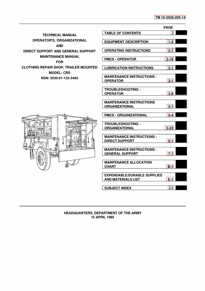
TECHNICAL MANUAL
OPERATOR'S, ORGANIZATIONAL
ANDDIRECT SUPPORT AND GENERAL SUPPORT
MAINTENANCE MANUAL
FOR
CLOTHING REPAIR SHOP, TRAILER MOUNTED
MODEL: CRS
NSN: 3530-01-133-3494

8/7/2019 TM 10-3530-205-10 CLOTHING REPAIR SHOP
http://slidepdf.com/reader/full/tm-10-3530-205-10-clothing-repair-shop 2/455
8/7/2019 TM 10-3530-205-10 CLOTHING REPAIR SHOP
http://slidepdf.com/reader/full/tm-10-3530-205-10-clothing-repair-shop 3/455
TM 10-3530-205-14
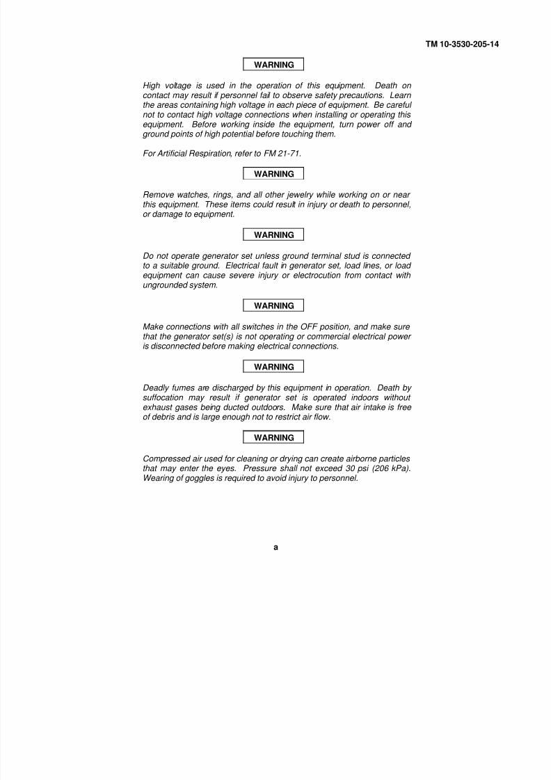
WARNING
High voltage is used in the operation of this equipment. Death on contact may result if personnel fail to observe safety precautions. Learn the areas containing high voltage in each piece of equipment. Be careful not to contact high voltage connections when installing or operating this
equipment. Before working inside the equipment, turn power off and ground points of high potential before touching them.
For Artificial Respiration, refer to FM 21-71.
WARNING
Remove watches, rings, and all other jewelry while working on or near this equipment. These items could result in injury or death to personnel,or damage to equipment.
WARNING
Do not operate generator set unless ground terminal stud is connected to a suitable ground. Electrical fault in generator set, load lines, or load equipment can cause severe injury or electrocution from contact with ungrounded system.
WARNING
Make connections with all switches in the OFF position, and make sure that the generator set(s) is not operating or commercial electrical power is disconnected before making electrical connections.
WARNING
Deadly fumes are discharged by this equipment in operation. Death by suffocation may result if generator set is operated indoors without exhaust gases being ducted outdoors. Make sure that air intake is free of debris and is large enough not to restrict air flow.
WARNING
Compressed air used for cleaning or drying can create airborne particles that may enter the eyes. Pressure shall not exceed 30 psi (206 kPa).Wearing of goggles is required to avoid injury to personnel.
a
8/7/2019 TM 10-3530-205-10 CLOTHING REPAIR SHOP
http://slidepdf.com/reader/full/tm-10-3530-205-10-clothing-repair-shop 4/455
8/7/2019 TM 10-3530-205-10 CLOTHING REPAIR SHOP
http://slidepdf.com/reader/full/tm-10-3530-205-10-clothing-repair-shop 5/455
TM 10-3530-205-14
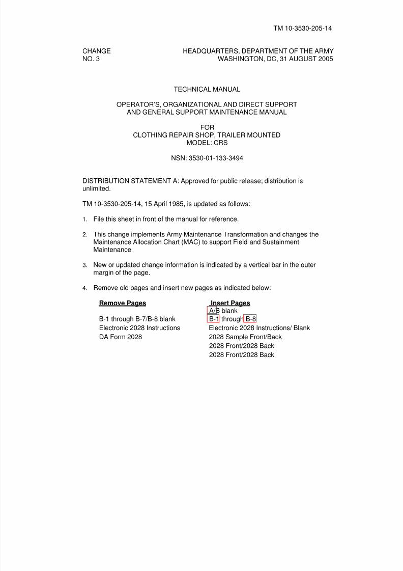
CHANGE HEADQUARTERS, DEPARTMENT OF THE ARMYNO. 3 WASHINGTON, DC, 31 AUGUST 2005
TECHNICAL MANUALOPERATOR’S, ORGANIZATIONAL AND DIRECT SUPPORT
AND GENERAL SUPPORT MAINTENANCE MANUAL
FORCLOTHING REPAIR SHOP, TRAILER MOUNTED
MODEL: CRS
NSN: 3530-01-133-3494
DISTRIBUTION STATEMENT A: Approved for public release; distribution isunlimited.
TM 10-3530-205-14, 15 April 1985, is updated as follows:
1. File this sheet in front of the manual for reference.
2. This change implements Army Maintenance Transformation and changes theMaintenance Allocation Chart (MAC) to support Field and SustainmentMaintenance.
3. New or updated change information is indicated by a vertical bar in the outermargin of the page.
4. Remove old pages and insert new pages as indicated below:
Remove Pages Insert PagesA/ B blank
B-1 through B-7/B-8 blank B-1 through B-8Electronic 2028 Instructions Electronic 2028 Instructions/ BlankDA Form 2028 2028 Sample Front/Back
2028 Front/2028 Back2028 Front/2028 Back
8/7/2019 TM 10-3530-205-10 CLOTHING REPAIR SHOP
http://slidepdf.com/reader/full/tm-10-3530-205-10-clothing-repair-shop 6/455
ARMY TM 10-3530-205-14C3
By Order of the Secretary of the Army:
PETER J. SCHOOMAKERGeneral, United States Army
Chief of Staff
Official:
SANDRA R. RILEY
Administrative Assistant to theSecretary of the Army0516417
Distribution: To be distributed in accordance with initial distribution number (IDN) 250319 requirements forTM 10-3530-205-14.
8/7/2019 TM 10-3530-205-10 CLOTHING REPAIR SHOP
http://slidepdf.com/reader/full/tm-10-3530-205-10-clothing-repair-shop 7/455
TM 10-3530-205-14CHANGE C 2
No. 2 HEADQUARTERSDEPARTMENT OF THE ARMY
WASHINGTON, D.C., 21 March 1988
Operator's, Organizationaland
Direct Support and General SupportMaintenance Manual
CLOTHING REPAIR SHOP, TRAILER MOUNTEDMODEL: CRS
NSN: 3530-01-133-3494
TM 10-3530-205-14, 15 April 1985, is changed as follows:
1. Remove and insert pages as indicated below. New or changed text material is indicated by a vertical bar inthe margin. An illustration change is indicated by a miniature pointing hand.
Remove pages Insert pages
C-9 and C-10 C-9 and C-10
2. Retain this sheet in front of manual for reference purposes.
By Order of the Secretary of the Army:
CARL E. VUONOGeneral, United States Army
Chief of Staff Official:
R. L. DILWORTHBrigadier General, United States Army
The Adjutant General
DISTRIBUTION:To be distributed in accordance with DA Form 12-25A, Operator's, Unit, Direct Support and General Support
Maintenance requirements for Clothing Repair Shop, Trailer Mounted, Model CRS.
}

8/7/2019 TM 10-3530-205-10 CLOTHING REPAIR SHOP
http://slidepdf.com/reader/full/tm-10-3530-205-10-clothing-repair-shop 8/455
8/7/2019 TM 10-3530-205-10 CLOTHING REPAIR SHOP
http://slidepdf.com/reader/full/tm-10-3530-205-10-clothing-repair-shop 9/455
TM 10-3530-205-14C 1
CHANGE HEADQUARTERSDEPARTMENT OF THE ARMY
NO. 1 WASHINGTON, D.C., 12 February 1986
Operator's, Organizational and Direct Support and General SupportMaintenance Manual for
CLOTHING REPAIR SHOP, TRAILER MOUNTEDMODEL: CRS, NSN: 3530-01-133-3494
TM 10-3530-205-14, 15 April 1985, is changed as follows:1. Remove and insert pages as indicated below. New or changed text material is indicated by a vertical bar in
the margin. An illustration change is indicated by a miniature pointing hand.
Remove pages Insert pages
i and ii i and iivii and viii vii and viii6-59 through 6-78 6-59 through 6-786-127 and 6-128 6-127 and 6-1286-129 and 6-130 6-1296-131 and 6-132 6-1326-153 and 6-154 6-153 and 6-1546-157 through 6-162 6-157 through 6-162B-5 through B-7/8 B-5 through B-7/8I-1 and I-2 I-1 and I-2I-5 and I-6 I-5 and I-6I-9 and I-10 I-9 and I-10I-13 and I-14 I-13 and I-14
2. Retain this sheet in front of manual for reference purposes.
By Order of the Secretary of the Army:
JOHN A. WICKHAM, JR.General, United States Army
Official: Chief of Staff
MILDRED E. HEDBERGBrigadier General, United States Army
The Adjutant General
DISTRIBUTION:To be distributed in accordance with DA Form 12-25A, Operator, Organizational and Direct Support and General
Support Maintenance Requirements for Clothing Repair Shop, Trailer Mounted, Model CRS.
}

8/7/2019 TM 10-3530-205-10 CLOTHING REPAIR SHOP
http://slidepdf.com/reader/full/tm-10-3530-205-10-clothing-repair-shop 10/455
8/7/2019 TM 10-3530-205-10 CLOTHING REPAIR SHOP
http://slidepdf.com/reader/full/tm-10-3530-205-10-clothing-repair-shop 11/455
TM 10-3530-205-14
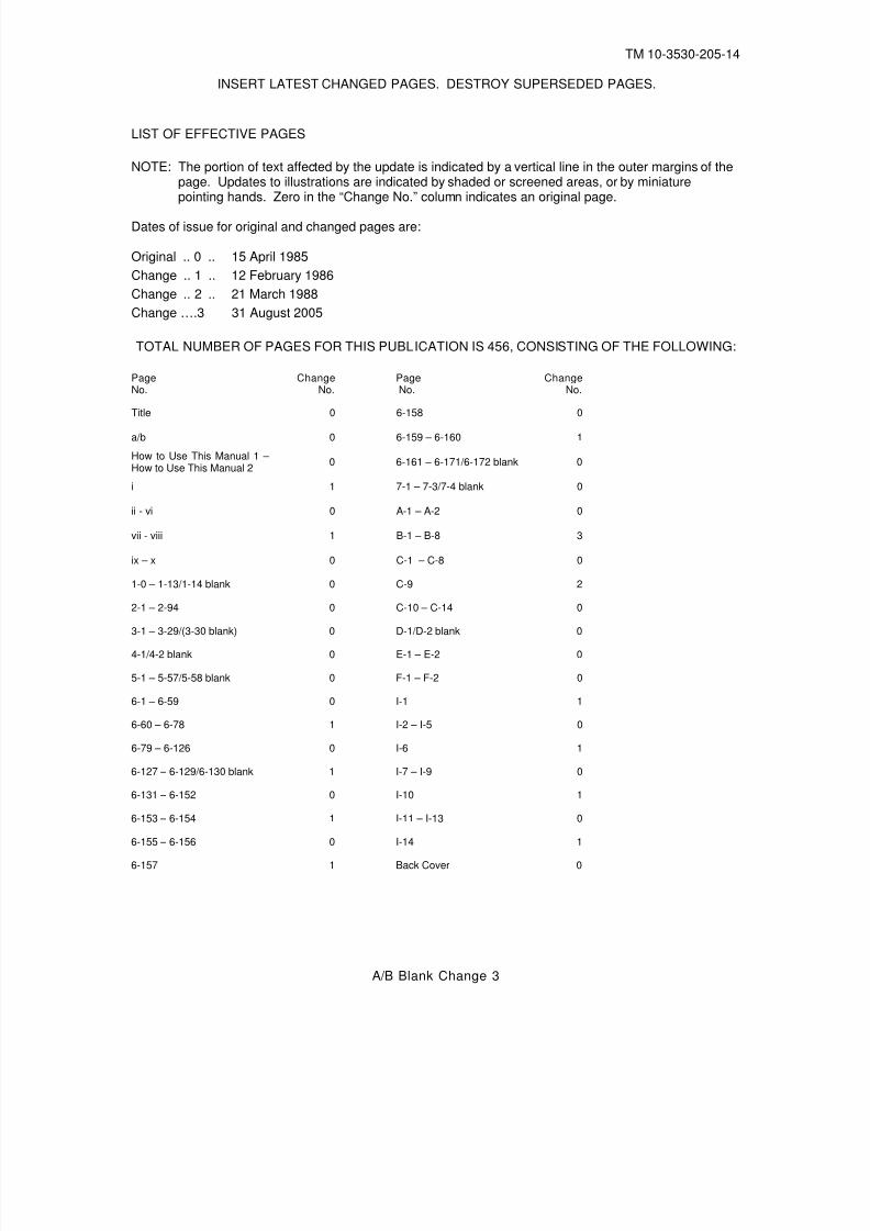
INSERT LATEST CHANGED PAGES. DESTROY SUPERSEDED PAGES.
A/B Blank Change 3
LIST OF EFFECTIVE PAGES
NOTE: The portion of text affected by the update is indicated by a vertical line in the outer margins of thepage. Updates to illustrations are indicated by shaded or screened areas, or by miniature
pointing hands. Zero in the “Change No.” column indicates an original page.
Dates of issue for original and changed pages are:
Original .. 0 .. 15 April 1985Change .. 1 .. 12 February 1986Change .. 2 .. 21 March 1988Change ….3 31 August 2005
TOTAL NUMBER OF PAGES FOR THIS PUBLICATION IS 456, CONSISTING OF THE FOLLOWING:
PageNo.
ChangeNo.
PageNo.
ChangeNo.
Title 0 6-158 0
a/b 0 6-159 – 6-160 1
How to Use This Manual 1 – How to Use This Manual 2 0 6-161 – 6-171/6-172 blank 0
i 1 7-1 – 7-3/7-4 blank 0
ii - vi 0 A-1 – A-2 0
vii - viii 1 B-1 – B-8 3
ix – x 0 C-1 – C-8 0
1-0 – 1-13/1-14 blank 0 C-9 2
2-1 – 2-94 0 C-10 – C-14 0
3-1 – 3-29/(3-30 blank) 0 D-1/D-2 blank 0
4-1/4-2 blank 0 E-1 – E-2 0
5-1 – 5-57/5-58 blank 0 F-1 – F-2 0
6-1 – 6-59 0 I-1 1
6-60 – 6-78 1 I-2 – I-5 0
6-79 – 6-126 0 I-6 1
6-127 – 6-129/6-130 blank 1 I-7 – I-9 0
6-131 – 6-152 0 I-10 1
6-153 – 6-154 1 I-11 – I-13 0
6-155 – 6-156 0 I-14 1
6-157 1 Back Cover 0

8/7/2019 TM 10-3530-205-10 CLOTHING REPAIR SHOP
http://slidepdf.com/reader/full/tm-10-3530-205-10-clothing-repair-shop 12/455
8/7/2019 TM 10-3530-205-10 CLOTHING REPAIR SHOP
http://slidepdf.com/reader/full/tm-10-3530-205-10-clothing-repair-shop 13/455
TM 10-3530-205-14
HOW TO USE THIS MANUAL
CONTENT
This manual is provided for your use in operating and maintaining the Clothing Repair Shop, Trailer-Mounted. You mustfamiliarize yourself with the entire maintenance procedures before beginning the maintenance task. Maintaining theclothing repair shop includes preventive maintenance checks and services, observation of trouble symptoms,troubleshooting procedures, and maintenance procedures to correct a malfunction.
MANUAL OVERVIEW
To help you become familiar with this new kind of manual as quickly as possible, spend some time looking through thepages. The manual has a new look that is different from the look of the manuals you've been using. You'll find that it's alot easier to use and you'll be able to find what you're looking for faster. In most cases, pictures have replaced words toshow you how to operate, inspect, service, replace or repair those items or components that are your responsibility tooperate or maintain. The following is a list and description of each chapter and appendix.
a. Chapter 1 - Introduction.Contains general information, purpose of equipment, equipment description, and technical principles of operationregarding the complete clothing repair shop.
b. Chapter 2 - Operating Instructions.Contains operating instructions, both under usual and unusual conditions, operation of auxiliary equipment, andpreventive maintenance checks and services (PMCS).
c. Chapter 3 - Operator Maintenance Instructions.Contains lubrication instructions, operator troubleshooting, and maintenance procedures.
d. Chapter 4 - Maintenance of Auxiliary Equipment.Contains references to technical manuals covering the auxiliary equipment.
e. Chapter 5 - Organizational Maintenance Instructions.Contains detailed maintenance procedures for the organizational maintenance technician. Also included are instructionsfor service upon receipt of equipment, and preventive maintenance checks services (PMCS).
f. Chapter 6 - Direct Support Maintenance Instructions.Contains the maintenance instructions for the clothing repair shop at the direct support maintenance level.
How to Use This Manual - 1
8/7/2019 TM 10-3530-205-10 CLOTHING REPAIR SHOP
http://slidepdf.com/reader/full/tm-10-3530-205-10-clothing-repair-shop 14/455
TM 10-3530-205-14
MANUAL OVERVIEW - Continued
g. Chapter 7 - General Support Maintenance Instructions.Contains the maintenance instructions for the clothing repair shop at the general support maintenance level.
h. Appendix A - References.Contains a listing of all forms and technical manuals referred to in this manual.
i. Appendix B - Maintenance Allocation Chart (MAC).Contains a listing of all maintenance significant items and their applicable maintenance functions assigned to eachmaintenance category.
j. Appendix C - Components of End Item and Basic Issue Items List.Contains listings for components of the end item, and basic issue items.
k. Appendix D - Additional Authorization List (AAL).Not Applicable.
I. Appendix E - Expendable/Durable Supplies and Materials List.Contains an alphabetized tabular listing of all consumable items used in the maintenance or repair of the clothing repairshop.
m. Appendix F - Illustrated List of Manufactured Items.Contains complete instructions for making items authorized to be manufactured or fabricated at organizationalmaintenance.
n. INDEX.Contains an alphabetical index by subject matter contained in this manual.
How to Use This Manual - 2
8/7/2019 TM 10-3530-205-10 CLOTHING REPAIR SHOP
http://slidepdf.com/reader/full/tm-10-3530-205-10-clothing-repair-shop 15/455
TM 10-3530-205-14
TECHNICAL MANUAL HEADQUARTERSDEPARTMENT OF THE ARMY
WASHINGTON, D.C. 15 April 1985
OPERATOR'S, ORGANIZATIONAL, DIRECT SUPPORT,AND GENERAL SUPPORT MAINTENANCE MANUAL
FORCLOTHING REPAIR SHOP, TRAILER MOUNTED
MODEL NO. CRSNSN: 3530-01-133-3494
REPORTING ERRORS AND RECOMMENDING IMPROVEMENTS
You can help improve this manual. If you find any mistake or if you know of a way to improve the procedures, please letus know. Mail your letter, DA Form 2028 (Recommended Changes to Publications and Blank Forms), or DA Form 2028-2 located in the back of this manual direct to: Commander, U.S. Army Troop Support Command, ATTN: AMSTR-MCTS,4300 Goodfellow Boulevard, St. Louis, MO 63120-1798. A reply will be furnished directly to you.
TABLE OF CONTENTSPage
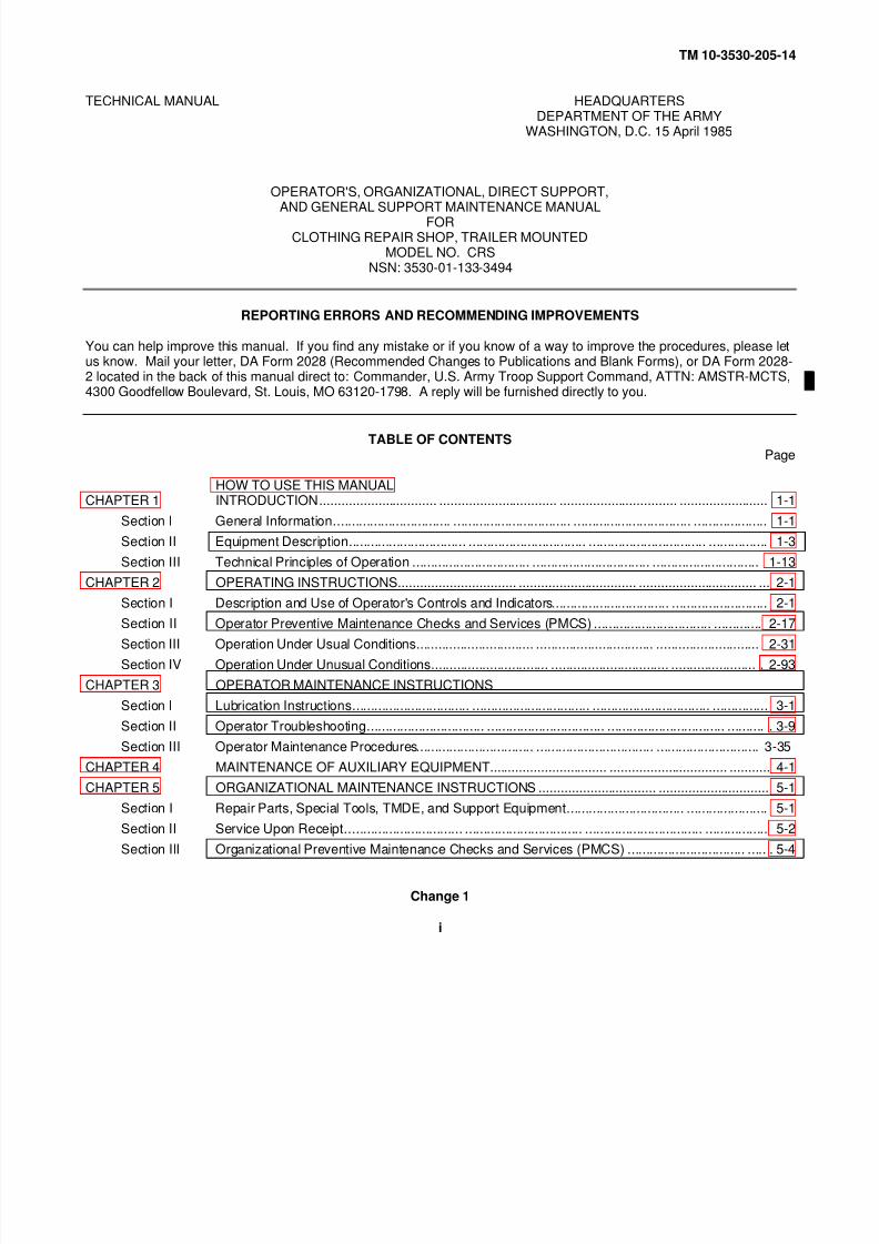
HOW TO USE THIS MANUALCHAPTER 1 INTRODUCTION................................ ................................ ................................ ........................ 1-1
Section I General Information................................ ................................ ................................ .................... 1-1Section II Equipment Description................................ ................................ ................................ ................ 1-3Section III Technical Principles of Operation ................................ ................................ ............................. 1-13
CHAPTER 2 OPERATING INSTRUCTIONS................................ ................................ ................................ ... 2-1
Section I Description and Use of Operator's Controls and Indicators................................ .......................... 2-1Section II Operator Preventive Maintenance Checks and Services (PMCS) ................................ ............. 2-17Section III Operation Under Usual Conditions................................ ................................ ............................ 2-31Section IV Operation Under Unusual Conditions................................ ................................ ....................... . 2-93
CHAPTER 3 OPERATOR MAINTENANCE INSTRUCTIONSSection I Lubrication Instructions................................ ................................ ................................ ............... 3-1Section II Operator Troubleshooting................................ ................................ ................................ .......... . 3-9Section III Operator Maintenance Procedures................................ ................................ ............................ 3-35
CHAPTER 4 MAINTENANCE OF AUXILIARY EQUIPMENT................................ ................................ ........... 4-1CHAPTER 5 ORGANIZATIONAL MAINTENANCE INSTRUCTIONS ................................ .............................. 5-1
Section I Repair Parts, Special Tools, TMDE, and Support Equipment................................ ...................... 5-1Section II Service Upon Receipt................................ ................................ ................................ ................. 5-2Section III Organizational Preventive Maintenance Checks and Services (PMCS) ................................ ..... . 5-4
Change 1
i
8/7/2019 TM 10-3530-205-10 CLOTHING REPAIR SHOP
http://slidepdf.com/reader/full/tm-10-3530-205-10-clothing-repair-shop 16/455
TM 10-3530-205-14
TABLE OF CONTENTS - ContinuedPage
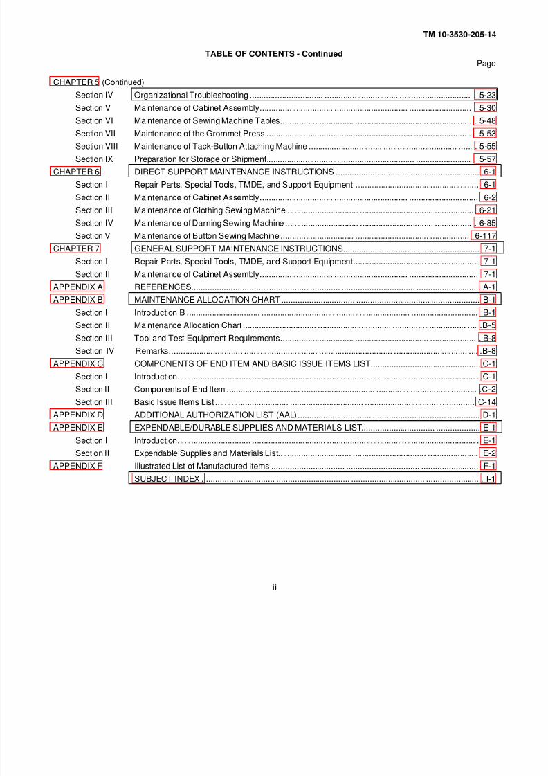
CHAPTER 5 (Continued)Section IV Organizational Troubleshooting ................................ ................................ ............................... . 5-23Section V Maintenance of Cabinet Assembly................................ ................................ ........................... . 5-30
Section VI Maintenance of Sewing Machine Tables................................ ................................ .................. . 5-48Section VII Maintenance of the Grommet Press................................ ................................ ......................... . 5-53Section VIII Maintenance of Tack-Button Attaching Machine ................................ ................................ ...... . 5-55Section IX Preparation for Storage or Shipment................................ ................................ ........................ . 5-57
CHAPTER 6 DIRECT SUPPORT MAINTENANCE INSTRUCTIONS ................................ .............................. 6-1Section I Repair Parts, Special Tools, TMDE, and Support Equipment ................................ ..................... 6-1Section II Maintenance of Cabinet Assembly................................ ................................ .............................. 6-2Section III Maintenance of Clothing Sewing Machine................................ ................................ ................. 6-21Section IV Maintenance of Darning Sewing Machine ................................ ................................ ................ . 6-85Section V Maintenance of Button Sewing Machine ................................ ................................ ................. 6-117
CHAPTER 7 GENERAL SUPPORT MAINTENANCE INSTRUCTIONS................................ ........................... 7-1Section I Repair Parts, Special Tools, TMDE, and Support Equipment................................ ...................... 7-1Section II Maintenance of Cabinet Assembly................................ ................................ .............................. 7-1
APPENDIX A REFERENCES................................ ................................ ................................ .......................... . A-1APPENDIX B MAINTENANCE ALLOCATION CHART ................................ ................................ ..................... B-1
Section I Introduction B ................................ ................................ ................................ ............................. B-1Section II Maintenance Allocation Chart ................................ ................................ ................................ .... .B-5Section III Tool and Test Equipment Requirements................................ ................................ .................... . B-8Section IV Remarks................................ ................................ ................................ ................................ .... .B-8
APPENDIX C COMPONENTS OF END ITEM AND BASIC ISSUE ITEMS LIST................................ ............... C-1
Section I Introduction................................ ................................ ................................ ................................ . C-1Section II Components of End Item ................................ ................................ ................................ ........... .C-2Section III Basic Issue Items List ................................ ................................ ................................ ............... C-14
APPENDIX D ADDITIONAL AUTHORIZATION LIST (AAL) ................................ ................................ .............. D-1APPENDIX E EXPENDABLE/DURABLE SUPPLIES AND MATERIALS LIST................................ ................... E-1
Section I Introduction................................ ................................ ................................ ................................ . E-1Section II Expendable Supplies and Materials List................................ ................................ ...................... E-2
APPENDIX F Illustrated List of Manufactured Items ................................ ................................ ......................... F-1SUBJECT INDEX .. .............................. ................................ ................................ ....................... . I-1
ii
8/7/2019 TM 10-3530-205-10 CLOTHING REPAIR SHOP
http://slidepdf.com/reader/full/tm-10-3530-205-10-clothing-repair-shop 17/455
TM 10-3530-205-14
LIST OF ILLUSTRATIONS
Figure Title PageNo. No.
1-1 Clothing Repair Shop, Trailer Mounted ................................ ................................ ...................... 1-01-2 Curb Side................................ ................................ ................................ ................................ .. .1-51-3 Street Side................................ ................................ ................................ ................................ .1-51-4 Rear View................................ ................................ ................................ ................................ . .1-61-5 Folding Stands................................ ................................ ................................ ........................... 1-61-6 Clothing Sewing Machine................................ ................................ ................................ ........... 1-71-7 Darning Sewing Machine ................................ ................................ ................................ ........... 1-71-8 Button Sewing Machine ................................ ................................ ................................ ............. 1-71-9 Grommet Press Machine ................................ ................................ ................................ ........... 1-81-10 Tack-Button Attaching Machine ................................ ................................ ................................ .1-81-11 Identification Plate, Clothing Repair Shop, Trailer Mounted (Mounted on front, street side) ........ 1-91-12 Instruction Plate, Lifting Instructions (Mounted on front, curb side) ................................ ............ 1-91-13 Instruction Plate - Box No. 1 Storage List................................ ................................ ................... 1-101-14 Instruction Plate - Box No. 2 Storage List................................ ................................ ................... 1-101-15 Instruction Plate - Box No. 3 Storage List................................ ................................ ................... 1-101-16 Instruction Plate - Box No. 4 Storage List................................ ................................ ................... 1-101-17 Identification Plate Fire Extinguisher Storage (Mounted on curb side, front) ............................... 1-112-1 Unhooking the Trailer................................ ................................ ................................ ................ . 2-332-2 Lowering the Rear Support Leg................................ ................................ ................................ . .2-342-3 Opening the Side Doors................................ ................................ ................................ ............ . 2-342-4 Opening the End Gates................................ ................................ ................................ ............. . 2-352-5 Generator Set, Removal ................................ ................................ ................................ ........... . 2-352-6 Table Top, Removal ................................ ................................ ................................ ................. . 2-372-7 Folding Stands, Removal................................ ................................ ................................ .......... . 2-372-8 Storage Boxes, Removal ................................ ................................ ................................ .......... . 2-382-9 Clothing Sewing Machine Table, Assembly................................ ................................ ............... . 2-382-10 Clothing Sewing Machine Table, Installation ................................ ................................ ............. . 2-402-11 Darning Sewing Machine Table, Assembly................................ ................................ ................ . 2-42
2-12 Darning Sewing Machine Table, Installation................................ ................................ .............. . 2-432-13 Button Sewing Machine Table, Assembly................................ ................................ .................. . 2-452-14 Button Sewing Machine Table, Installation................................ ................................ ................ . 2-452-15 Grommet Press, Set-Up................................ ................................ ................................ ............ . 2-462-16 Tack-Button Attaching Machine, Set-Up................................ ................................ .................... . 2-472-17 Schematic Diagram Showing Sewing Machines Connected to Generator Set ........................... . 2-482-18 Left-Twist Thread................................ ................................ ................................ ...................... . 2-502-19 Lowering Presser Foot................................ ................................ ................................ .............. . 2-512-20 Checking Needle Straightness................................ ................................ ................................ . ..2-522-21 Needle, Installation ................................ ................................ ................................ ................... . 2-522-22 Thread Cone, Installation................................ ................................ ................................ .......... . 2-532-23 Threading the Clothing Sewing Machine................................ ................................ ................... . 2-542-24 Slide Plate, Removal ................................ ................................ ................................ ................ . 2-55
2-25 Bobbin Case, Removal ................................ ................................ ................................ ............. . 2-552-26 Bobbin Winding ................................ ................................ ................................ ........................ . 2-56
iii
8/7/2019 TM 10-3530-205-10 CLOTHING REPAIR SHOP
http://slidepdf.com/reader/full/tm-10-3530-205-10-clothing-repair-shop 18/455
TM 10-3530-205-14
LIST OF ILLUSTRATIONS - Continued
Figure Title PageNo. No.
2-27 Proper Bobbin Winding................................ ................................ ................................ ............. . 2-572-28 Threading the Bobbin Case................................ ................................ ................................ ....... . 2-582-29 Slide Plate, Removal ................................ ................................ ................................ ................ . 2-582-30 Bobbin Case, Installation ................................ ................................ ................................ .......... . 2-592-31 Catching the Bobbin Thread................................ ................................ ................................ ...... . 2-592-32 Stitch Length, Adjustment ................................ ................................ ................................ ......... . 2-602-33 Checking Thread Tension................................ ................................ ................................ ........ .. 2-622-34 Bobbin Thread Tension, Adjustment ................................ ................................ ......................... . 2-632-35 Needle Thread Tension, Adjustment................................ ................................ ......................... . 2-632-36 Foot Presser, Adjustment................................ ................................ ................................ .......... . 2-642-37 Left Twist Thread................................ ................................ ................................ ...................... . 2-652-38 Thread Cone, Installation................................ ................................ ................................ .......... . 2-662-39 Threading the Sewing Machine ................................ ................................ ................................ .2-662-40 Bobbin Case, Removal ................................ ................................ ................................ ............. . 2-672-41 Bobbin Case, Installation ................................ ................................ ................................ .......... . 2-682-42 Darning Material ................................ ................................ ................................ ....................... . 2-702-43 Checking Thread Tensions................................ ................................ ................................ ........ . 2-712-44 Bobbin Thread Tension, Adjustment ................................ ................................ .......................... 2-712-45 Needle Thread Tension, Adjustment................................ ................................ ......................... . 2-722-46 Presser Foot, Adjustment................................ ................................ ................................ .......... . 2-722-47 Pressure Regulator, Thumbscrew................................ ................................ ............................. . 2-732-48 Left Twist Thread................................ ................................ ................................ ...................... . 2-742-49 Checking Needle Straightness................................ ................................ ................................ . ..2-752-50 Needle, Installation ................................ ................................ ................................ ................... . 2-752-51 Button Sewing Machine Threading................................ ................................ ............................ . 2-762-52 Thread Tension, Adjustment................................ ................................ ................................ ..... . 2-772-53 Button Clamp Opening, Adjustment ................................ ................................ .......................... . 2-782-54 Two-Hole/Four-Hole Button Selection................................ ................................ ....................... . 2-782-55 Chuck and Die, Installation ................................ ................................ ................................ ....... . 2-80
2-56 Snap Fastener, Installation................................ ................................ ................................ ........ . 2-812-57 Die, Installation................................ ................................ ................................ ......................... . 2-822-58 Tack Buttons................................ ................................ ................................ ............................. . 2-832-59 Tack-Button Attaching Machine, Removal ................................ ................................ ................ . 2-842-60 Grommet Press, Removal................................ ................................ ................................ ........ .. 2-852-61 Button Sewing Machine, Removal ................................ ................................ ............................ . 2-862-62 Button Sewing Machine Table, Disassembly................................ ................................ ............. . 2-862-63 Darning Sewing Machine, Removal ................................ ................................ .......................... . 2-872-64 Darning Sewing Machine Table, Disassembly................................ ................................ ........... . 2-892-65 Clothing Sewing Machine, Removal................................ ................................ .......................... . 2-902-66 Storage Boxes, Installation ................................ ................................ ................................ ....... . 2-912-67 Folding Stands, Installation................................ ................................ ................................ ....... . 2-912-68 Table Tops, Installation................................ ................................ ................................ ............. . 2-92
2-69 Generator Set, Installation ................................ ................................ ................................ ........ . 2-922-70 Lowering the Rear Support Leg................................ ................................ ................................ . .2-932-71 Pulley, Installation................................ ................................ ................................ ..................... . 2-94
iv
8/7/2019 TM 10-3530-205-10 CLOTHING REPAIR SHOP
http://slidepdf.com/reader/full/tm-10-3530-205-10-clothing-repair-shop 19/455
TM 10-3530-205-14
LIST OF ILLUSTRATIONS - Continued
Figure Title PageNo. No.
3-5 Typical Belt Adjustment ................................ ................................ ................................ ............. 3-365-1 Chair Holddown and Stand Container, Removal ................................ ................................ ....... . 5-315-2 Chair Holddown and Stand Container, Installation................................ ................................ ..... . 5-325-3 Lifting Loop Assembly, Removal ................................ ................................ ............................... . 5-335-4 Lifting Loop Assembly, Installation................................ ................................ ............................ . 5-345-5 Leg Latch, Repair................................ ................................ ................................ ...................... . 5-365-6 Leg Assembly, Replacement................................ ................................ ................................ .... .. 5-365-7 Top Stiffener, Replacement ................................ ................................ ................................ ...... . 5-375-8 Clothing Sewing Machine Tray, Removal................................ ................................ .................. . 5-385-9 Holddown Strap, Replacement................................ ................................ ................................ .. .5-395-10 Rubber Bumpers, Replacement ................................ ................................ ................................ .5-395-11 Felt Shock Absorber, Replacement................................ ................................ ........................... . 5-405-12 Handle, Replacement ................................ ................................ ................................ ............... . 5-405-13 Clothing Sewing Machine Tray, Installation................................ ................................ ............... . 5-415-14 Darning Sewing Machine Tray, Removal ................................ ................................ .................. . 5-425-15 Holddown Strap, Replacement................................ ................................ ................................ . ..5-435-16 Shock Absorber, Replacement................................ ................................ ................................ . ..5-445-17 Handle, Replacement ................................ ................................ ................................ ............... . 5-445-18 Darning Sewing Machine Tray, Installation................................ ................................ ................ . 5-455-19 Button Sewing Machine Tray, Removal ................................ ................................ .................... . 5-465-20 Holddown Straps, Replacement................................ ................................ ................................ .5-475-21 Shock Absorber, Replacement................................ ................................ ................................ . ..5-475-22 Button Sewing Machine Tray, Installation................................ ................................ .................. . 5-485-23 Knee Lifter Assembly, Removal ................................ ................................ ................................ .5-515-24 Knee Lifter Assembly, Installation ................................ ................................ ............................. . 5-526-1 Connecting the Chain Hoist................................ ................................ ................................ ....... . 6-36-2 Holddown Clamp, Unhooking................................ ................................ ................................ .... .6-36-3 Connecting the Hoist................................ ................................ ................................ ................. . 6-56-4 Holddown Clamp, Hook-Up................................ ................................ ................................ ....... . 6-5
6-5 Side Door, Removal................................ ................................ ................................ .................. . 6-76-6 Hinge, Replacement ................................ ................................ ................................ ................. . 6-76-7 Gasket, Replacement ................................ ................................ ................................ ............... . 6-86-8 Latch Assembly, Replacement................................ ................................ ................................ .. .6-96-9 Hasp, Replacement ................................ ................................ ................................ .................. . 6-96-10 Stay, Replacement ................................ ................................ ................................ ................... . 6-106-11 Side Door, Installation................................ ................................ ................................ ............... . 6-106-12 Rear Door, Removal ................................ ................................ ................................ ................. . 6-126-13 Side Door, Installation................................ ................................ ................................ ............... . 6-136-14 Holddown Clamp Assembly, Removal ................................ ................................ ....................... 6-146-15 Holddown Clamp Assembly, Installation................................ ................................ .................... . 6-156-16 Generator Track and Holddown Assembly, Removal ................................ ................................ .6-16
v
8/7/2019 TM 10-3530-205-10 CLOTHING REPAIR SHOP
http://slidepdf.com/reader/full/tm-10-3530-205-10-clothing-repair-shop 20/455
TM 10-3530-205-14
LIST OF ILLUSTRATIONS - Continued
Figure Title PageNo. No.
6-17 Generator Track and Holddown Assembly, Installation................................ ............................... 6-176-18 Four Receptacle Junction Box Schematic ................................ ................................ ................. . 6-206-19 Three Receptacle Junction Box Schematic ................................ ................................ ............... . 6-206-20 Male Connector Schematic ................................ ................................ ................................ ....... . 6-216-21 Needle Thread Guide, Removal................................ ................................ ................................ .6-226-22 Thread Guides, Removal ................................ ................................ ................................ .......... . 6-236-23 Needle Thread Guide, Disassembly................................ ................................ .......................... . 6-236-24 Needle Thread Guide, Assembly................................ ................................ ............................... . 6-256-25 Thread Guides, Installation ................................ ................................ ................................ ....... . 6-256-26 Needle Thread Guide, Installation................................ ................................ ............................. . 6-266-27 Face Plate, Removal ................................ ................................ ................................ ................ . 6-276-28 Thread Tension Adjuster, Removal................................ ................................ ........................... . 6-286-29 Face Plate, Disassembly................................ ................................ ................................ ........... . 6-286-30 Face Plate, Assembly ................................ ................................ ................................ ............... . 6-306-31 Thread Tension Adjuster, Installation ................................ ................................ ........................ . 6-306-32 Face Plate, Installation................................ ................................ ................................ .............. . 6-316-33 Top Cover, Removal................................ ................................ ................................ ................. . 6-336-34 Upper (Arm) Oil Reservoir, Removal ................................ ................................ ........................ . 6-336-35 Upper (Arm) Oil Lubricating System, Removal ................................ ................................ .......... . 6-346-36 Upper (Arm) Oil Lubricating System, Installation................................ ................................ ....... . 6-356-37 Upper (Arm) Oil Reservoir, Installation................................ ................................ ...................... . 6-366-38 Top Cover, Installation................................ ................................ ................................ .............. . 6-366-39 Pulley, Removal ................................ ................................ ................................ ....................... . 6-376-40 Pulley, Installation................................ ................................ ................................ ..................... . 6-386-41 Feed Regulator Control, Removal................................ ................................ ............................. . 6-406-42 Feed Regulator Control, Installation................................ ................................ ........................... 6-416-43 Lower (Bed) Lubricating Oil System, Removal ................................ ................................ .......... . 6-436-44 Lower (Bed) Lubricating Oil System, Installation ................................ ................................ ....... . 6-446-45 Slide and Throat Plates, Removal................................ ................................ ............................. . 6-45
6-46 Bobbin Case Positioning Bracket, Removal ................................ ................................ .............. . 6-466-47 Feed Rock Shaft, Removal ................................ ................................ ................................ ....... . 6-466-48 Feed Lifting Hook Shaft, Removal ................................ ................................ ............................ . 6-476-49 Feed Bar, Removal................................ ................................ ................................ ................... . 6-476-50 Slide Plate, Disassembly................................ ................................ ................................ ........... . 6-486-51 Slide Plate, Assembly ................................ ................................ ................................ ............... . 6-496-52 Feed Bar, Installation................................ ................................ ................................ ................ . 6-496-53 Feed Lifting Hook Shaft, Installation................................ ................................ .......................... . 6-506-54 Feed Rock Shaft, Installation ................................ ................................ ................................ .... .6-506-55 Bobbin Case Positioning Bracket, Installation................................ ................................ ............ . 6-516-56 Slide and Throat Cover, Installation ................................ ................................ ........................... 6-516-57 Bobbin Case Assembly, Removal................................ ................................ ............................. . 6-536-58 Bobbin Drive Gear, Removal ................................ ................................ ................................ .... .6-53
6-59 Bobbin Drive Shaft, Removal ................................ ................................ ................................ .... .6-546-60 Bobbin Drive Shaft and Gears, Installation................................ ................................ ................ . 6-556-61 Bobbin Case Assembly, Installation ................................ ................................ .......................... . 6-566-62 Bed and Arm, Disassembly................................ ................................ ................................ ...... .. 6-586-63 Bed and Arm, Assembly................................ ................................ ................................ ............ . 6-59
vi
8/7/2019 TM 10-3530-205-10 CLOTHING REPAIR SHOP
http://slidepdf.com/reader/full/tm-10-3530-205-10-clothing-repair-shop 21/455
TM 10-3530-205-14
LIST OF ILLUSTRATIONS - Continued
Figure Title PageNo. No.
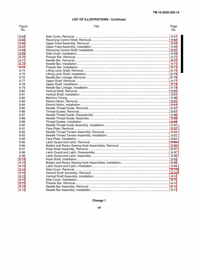
6-64 Side Cover, Removal................................ ................................ ................................ ................ . 6-616-65 Reversing Control Shaft, Removal ................................ ................................ ............................ . 6-626-66 Upper Feed Assembly, Removal................................ ................................ ............................... . 6-646-67 Upper Feed Assembly, Installation................................ ................................ ............................ . 6-656-68 Reversing Control Shaft, Installation ................................ ................................ ......................... . 6-676-69 Side Cover, Installation................................ ................................ ................................ ............. . 6-686-70 Presser Bar, Removal................................ ................................ ................................ ............... . 6-706-71 Needle Bar, Removal................................ ................................ ................................ ................ . 6-706-72 Needle Bar, Installation................................ ................................ ................................ ............. . 6-726-73 Presser Bar, Installation................................ ................................ ................................ ............ . 6-736-74 Lifting Lever Shaft, Removal ................................ ................................ ................................ .... .6-756-75 Lifting Lever Shaft, Installation................................ ................................ ................................ .. .6-756-76 Needle Bar Linkage, Removal ................................ ................................ ................................ .. .6-766-77 Upper Shaft, Removal ................................ ................................ ................................ .............. . 6-776-78 Upper Shaft, Installation................................ ................................ ................................ ............ . 6-786-79 Needle Bar Linkage, Installation................................ ................................ ................................ .6-786-80 Vertical Shaft, Removal ................................ ................................ ................................ ............ . 6-806-81 Vertical Shaft, Installation ................................ ................................ ................................ ......... . 6-816-82 Machine Timing ................................ ................................ ................................ ........................ . 6-826-83 Electric Motor, Removal................................ ................................ ................................ ............ . 6-836-84 Electric Motor, Installation................................ ................................ ................................ ......... . 6-846-85 Needle Thread Guide, Removal................................ ................................ ................................ .6-876-86 Thread Guides, Removal ................................ ................................ ................................ .......... . 6-876-87 Needle Thread Guide, Disassembly................................ ................................ .......................... . 6-886-88 Needle Thread Guide, Assembly................................ ................................ ............................... . 6-896-89 Thread Guides, Installation ................................ ................................ ................................ ....... . 6-896-90 Needle Thread Guide Assembly, Installation................................ ................................ ............. . 6-906-91 Face Plate, Removal ................................ ................................ ................................ ................ . 6-926-92 Needle Thread Tension Assembly, Removal................................ ................................ ............. . 6-92
6-93 Needle Thread Tension Assembly, Installation................................ ................................ .......... . 6-936-94 Face Plate, Installation................................ ................................ ................................ .............. . 6-946-95 Latch Guard and Latch, Removal................................ ................................ .............................. . 6-966-96 Bobbin and Rotary Sewing Hook Assemblies, Removal................................ ............................ . 6-966-97 Hook Shaft Assembly, Removal................................ ................................ ................................ .6-976-98 Latch Guard and Latch, Disassembly................................ ................................ ........................ . 6-976-99 Latch Guard and Latch, Assembly................................ ................................ ............................. . 6-986-100 Hook Shaft, Installation................................ ................................ ................................ ............. . 6-996-101 Bobbin and Rotary Sewing Hook Assemblies, Installation................................ .......................... 6-996-102 Latch Guard and Latch, Installation................................ ................................ ............................ 6-996-103 Side Cover, Removal................................ ................................ ................................ ................ . 6-1016-104 Vertical Shaft Assembly, Removal ................................ ................................ ............................. 6-1016-105 Vertical Shaft Assembly, Installation ................................ ................................ .......................... 6-103
6-106 Side Cover, Installation................................ ................................ ................................ ............. . 6-1036-107 Presser Bar, Removal................................ ................................ ................................ ............... . 6-1056-108 Needle Bar Assembly, Removal................................ ................................ ................................ .6-1056-109 Needle Bar Assembly, Installation................................ ................................ ............................. . 6-107
Change 1
vii
8/7/2019 TM 10-3530-205-10 CLOTHING REPAIR SHOP
http://slidepdf.com/reader/full/tm-10-3530-205-10-clothing-repair-shop 22/455
TM 10-3530-205-14
LIST OF ILLUSTRATIONS - Continued
Figure Title PageNo. No.
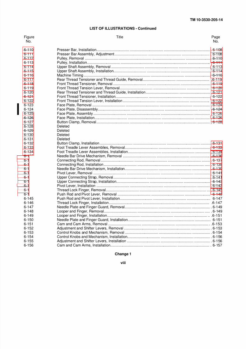
6-110 Presser Bar, Installation................................ ................................ ................................ ............ . 6-1086-111 Presser Bar Assembly, Adjustment ................................ ................................ ........................... . 6-1086-112 Pulley, Removal ................................ ................................ ................................ ........................ 6-1106-113 Pulley, Installation................................ ................................ ................................ ...................... 6-1116-114 Upper Shaft Assembly, Removal ................................ ................................ ............................... 6-1136-115 Upper Shaft Assembly, Installation................................ ................................ ............................. 6-1146-116 Machine Timing ................................ ................................ ................................ ......................... 6-1166-117 Rear Thread Tensioner and Thread Guide, Removal................................ ................................ .6-1196-118 Front Thread Tensioner, Removal ................................ ................................ ............................. 6-1196-119 Front Thread Tension Lever, Removal................................ ................................ ...................... . 6-1206-120 Rear Thread Tensioner and Thread Guide, Installation................................ .............................. 6-1216-121 Front Thread Tensioner, Installation................................ ................................ ........................... 6-1226-122 Front Thread Tension Lever, Installation................................ ................................ ................... . 6-1226-123 Face Plate, Removal ................................ ................................ ................................ ................ . 6-1246-124 Face Plate, Disassembly................................ ................................ ................................ ........... . 6-1246-125 Face Plate, Assembly ................................ ................................ ................................ ............... . 6-1266-126 Face Plate, Installation................................ ................................ ................................ .............. . 6-1266-127 Button Clamp, Removal ................................ ................................ ................................ ............ . 6-1286-128 Deleted6-129 Deleted6-130 Deleted6-131 Deleted6-132 Button Clamp, Installation................................ ................................ ................................ .......... 6-1316-133 Foot Treadle Lever Assemblies, Removal................................ ................................ ................. . 6-1336-134 Foot Treadle Lever Assemblies, Installation................................ ................................ .............. . 6-1346-135 Needle Bar Drive Mechanism, Removal ................................ ................................ ................... . 6-1366-136 Connecting Rod, Removal ................................ ................................ ................................ ........ . 6-1376-137 Connecting Rod, Installation ................................ ................................ ................................ ..... . 6-138
6-138 Needle Bar Drive Mechanism, Installation................................ ................................ ................. . 6-1396-139 Pivot Lever, Removal ................................ ................................ ................................ ............... . 6-1416-140 Upper Connecting Strap, Removal ................................ ................................ ............................. 6-1416-141 Upper Connecting Strap, Installation................................ ................................ .......................... 6-1436-142 Pivot Lever, Installation ................................ ................................ ................................ ............ . 6-1436-143 Thread Lock Finger, Removal................................ ................................ ................................ ... . 6-1456-144 Push Rod and Pivot Lever, Removal ................................ ................................ ......................... 6-1456-145 Push Rod and Pivot Lever, Installation................................ ................................ ....................... 6-1476-146 Thread Lock Finger, Installation................................ ................................ ................................ .6-1476-147 Needle Plate and Finger Guard, Removal................................ ................................ ................. . 6-1496-148 Looper and Finger, Removal................................ ................................ ................................ ..... . 6-1496-149 Looper and Finger, Installation................................ ................................ ................................ .. .6-1516-150 Needle Plate and Finger Guard, Installation................................ ................................ ............... 6-151
6-151 Cam and Cam Arms, Removal ................................ ................................ ................................ . .6-1536-152 Adjustment and Shifter Levers, Removal ................................ ................................ .................. . 6-1536-153 Control Knobs and Mechanism, Removal ................................ ................................ ................. . 6-1546-154 Control Knobs and Mechanism, Installation................................ ................................ ............... . 6-1566-155 Adjustment and Shifter Levers, Installation ................................ ................................ ............... . 6-1566-156 Cam and Cam Arms, Installation................................ ................................ ............................... . 6-157
Change 1
viii
8/7/2019 TM 10-3530-205-10 CLOTHING REPAIR SHOP
http://slidepdf.com/reader/full/tm-10-3530-205-10-clothing-repair-shop 23/455
TM 10-3530-205-14
LIST OF ILLUSTRATIONS - Continued
Figure Title PageNo. No.
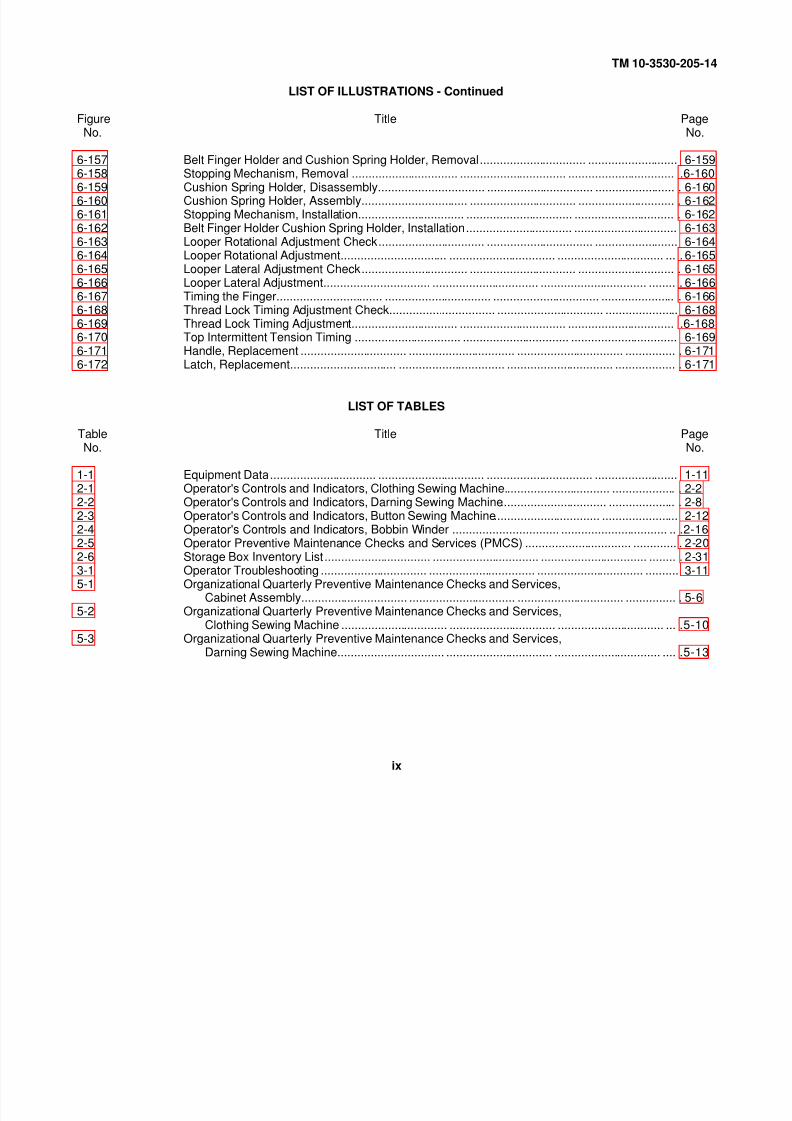
6-157 Belt Finger Holder and Cushion Spring Holder, Removal................................ ........................... 6-1596-158 Stopping Mechanism, Removal ................................ ................................ ................................ .6-1606-159 Cushion Spring Holder, Disassembly................................ ................................ ........................ . 6-1606-160 Cushion Spring Holder, Assembly................................ ................................ ............................. . 6-1626-161 Stopping Mechanism, Installation................................ ................................ .............................. . 6-1626-162 Belt Finger Holder Cushion Spring Holder, Installation................................ ............................... 6-1636-163 Looper Rotational Adjustment Check................................ ................................ ......................... 6-1646-164 Looper Rotational Adjustment................................ ................................ ................................ ... . 6-1656-165 Looper Lateral Adjustment Check................................ ................................ ............................. . 6-1656-166 Looper Lateral Adjustment................................ ................................ ................................ ........ . 6-1666-167 Timing the Finger................................ ................................ ................................ ...................... . 6-1666-168 Thread Lock Timing Adjustment Check................................ ................................ ...................... 6-1686-169 Thread Lock Timing Adjustment................................ ................................ ................................ .6-1686-170 Top Intermittent Tension Timing ................................ ................................ ................................ 6-1696-171 Handle, Replacement ................................ ................................ ................................ ............... . 6-1716-172 Latch, Replacement................................ ................................ ................................ .................. . 6-171
LIST OF TABLES
Table Title PageNo. No.
1-1 Equipment Data................................ ................................ ................................ ......................... 1-112-1 Operator's Controls and Indicators, Clothing Sewing Machine................................ ................... . 2-22-2 Operator's Controls and Indicators, Darning Sewing Machine................................ .................... . 2-82-3 Operator's Controls and Indicators, Button Sewing Machine................................ ....................... 2-122-4 Operator's Controls and Indicators, Bobbin Winder ................................ ................................ .. .2-162-5 Operator Preventive Maintenance Checks and Services (PMCS) ................................ ............. . 2-202-6 Storage Box Inventory List ................................ ................................ ................................ ........ . 2-313-1 Operator Troubleshooting ................................ ................................ ................................ .......... 3-115-1 Organizational Quarterly Preventive Maintenance Checks and Services,
Cabinet Assembly................................ ................................ ................................ ............... . 5-65-2 Organizational Quarterly Preventive Maintenance Checks and Services,
Clothing Sewing Machine ................................ ................................ ................................ ... .5-105-3 Organizational Quarterly Preventive Maintenance Checks and Services,
Darning Sewing Machine................................ ................................ ................................ .... .5-13
ix
8/7/2019 TM 10-3530-205-10 CLOTHING REPAIR SHOP
http://slidepdf.com/reader/full/tm-10-3530-205-10-clothing-repair-shop 24/455
TM 10-3530-205-14
LIST OF TABLES-Continued
Table Title PageNo. No.
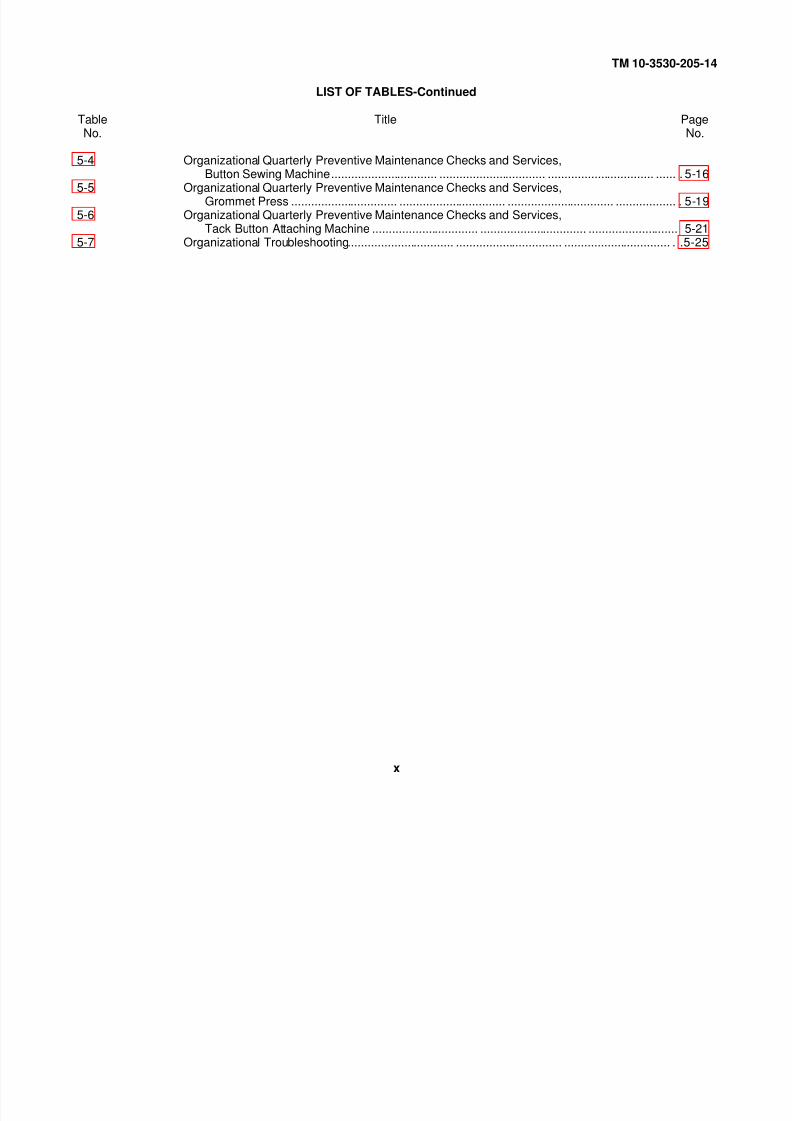
5-4 Organizational Quarterly Preventive Maintenance Checks and Services,Button Sewing Machine................................ ................................ ................................ ...... . 5-16
5-5 Organizational Quarterly Preventive Maintenance Checks and Services,Grommet Press ................................ ................................ ................................ .................. . 5-19
5-6 Organizational Quarterly Preventive Maintenance Checks and Services,Tack Button Attaching Machine ................................ ................................ ........................... 5-21
5-7 Organizational Troubleshooting................................ ................................ ................................ . .5-25
x
8/7/2019 TM 10-3530-205-10 CLOTHING REPAIR SHOP
http://slidepdf.com/reader/full/tm-10-3530-205-10-clothing-repair-shop 25/455
TM 10-3530-205-14
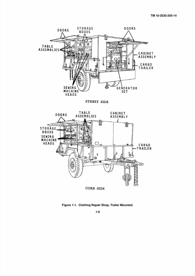
Figure 1-1. Clothing Repair Shop, Trailer Mounted.
1-0
8/7/2019 TM 10-3530-205-10 CLOTHING REPAIR SHOP
http://slidepdf.com/reader/full/tm-10-3530-205-10-clothing-repair-shop 26/455
TM 10-3530-205-14
CHAPTER 1
INTRODUCTION
Section I. GENERAL INFORMATION
Section II. EQUIPMENT DESCRIPTIONSection III. TECHNICAL PRINCIPLES OF OPERATION
SECTION I. GENERAL INFORMATION
Para. Para.Destruction of Army Materiel to Prevent Enemy Use.. ....1-3List of Abbreviations................................ ................... .... 1-6Maintenance Forms and Records............................... . ...1-2Nomenclature Cross-Reference List........................... .... 1-5
Preparation for Storage ................................ .............. ... 1-4Reporting of Equipment Improvement
Recommendations................................ ................ .... 1-7Scope................................ ................................ ........ .... 1-1
1-1. SCOPE.
a. Type of Manual. Operator's, Organizational, Direct Support, and General Support Maintenance Manual.
b. Model No. and Equipment Name. Model CRS clothing repair shop, trailer-mounted, transportable for fielduse.
c. Purpose of Equipment. The clothing repair shop is trailer-mounted ( fig. 1-1) and is complete with allequipment including auxiliary and support equipment necessary for the repair of clothing, and is designed for field usewhere it is normally set up in tents or temporary shelters.
d. Special Limitations on Equipment. Rated for 105 Vac to 120 Vac, 60 Hertz input power. Power may befurnished from a Government Furnished Equipment (GFE) generator set or from commercial power source.
1-2. MAINTENANCE FORMS AND RECORDS.
Department of the Army forms and procedures used for equipment will be those prescribed by DA PAM 738-750, TheArmy Maintenance Management System (TAMMS).
1-3. DESTRUCTION OF ARMY MATERIEL TO PREVENT ENEMY USE.
Command decision, in accordance with the tactical situation, will determine when destruction of the clothing repair shopwill be accomplished. For general destruction procedures for this equipment, refer to TM 750-244-3, Procedures forDestruction of Equipment to Prevent Enemy Use.
1-1
8/7/2019 TM 10-3530-205-10 CLOTHING REPAIR SHOP
http://slidepdf.com/reader/full/tm-10-3530-205-10-clothing-repair-shop 27/455
TM 10-3530-205-14
1-4. PREPARATION FOR STORAGE OR SHIPMENT.
Refer to Chapter 5 for preparation of the equipment for storage or shipment.
1-5. NOMENCLATURE CROSS-REFERENCE LIST.
This listing includes nomenclature cross-references used in this manual.
Common Name Official Nomenclature
Grommet Press Press, Grommet and Eyelet Attaching Machine
Tack-Button Attaching Machine Press, Grommet and Eyelet, Hand Operated
Clothing Sewing Machine Clothing Machine, Model C765
1-6. LIST OF ABBREVIATIONS.
AAL Additional Authorization mfg manufacturingList min minimum or minute
BII Basic Issue Items No. number(s)COEIL Components of End NSN National Stock Number
Item List P/N part numbercont continued para. paragraph(s)DA Department of the PMCS Preventive Maintenance
Army Checks &DS Direct Support ServicesEIRs Equipment Improvement qty Quantity
Recommendations RH right handES&ML Expendable Supplies TAMMS The Army MaintenanceF Direct Support Management SystemFM Field Manual TB Technical BulletinGS General Support TM Technical ManualHz Hertz TMDE Test Measurement andLH left hand Diagnostic EquipmentLO Lubrication Order U/M unit of measureMAC Maintenance Allocation Vac Volts alternating
Chart currentmax maximum wt weight
1-7. REPORTING EQUIPMENT IMPROVEMENT RECOMMENDATIONS (EIR's).
If your clothing repair shop needs improvement, let us know. Send us an EIR. You, the user, are the only one who cantell us what you don't like about your equipment. Let us know why you don't like the design. Put it on an SF 368 (QualityDeficiency Report). Mail it to us at: Commander, U.S. Army Troop Support. ATTN: AMSTR-QX, 4300 GoodfellowBlvd., St. Louis, MO 63120-1798. We'll send you a reply.
1-2
8/7/2019 TM 10-3530-205-10 CLOTHING REPAIR SHOP
http://slidepdf.com/reader/full/tm-10-3530-205-10-clothing-repair-shop 28/455
TM 10-3530-205-14
SECTION II. EQUIPMENT DESCRIPTION AND DATA
Para. Para.Equipment Characteristics,
Capabilities, andFeatures ................................ .............................. .. ..1-8
Equipment Data................................ ........................ ... 1-10Location and Description
of Major Components................................ ......... .... 1-9
1-8. EQUIPMENT CHARACTERISTICS, CAPABILITIES, AND FEATURES.
a. Self-contained unit including its operational support items.
b. Transportable on cargo trailer.
c. Clothing repair shop may be quickly dismounted from trailer.
d. Equipment housed in water proof cabinet.
e. Equipment may be powered by 120 Vac, 60 Hz, Government furnished auxiliary generator set or by 120 Vac,
60 Hz commercial power.
1-9. LOCATION AND DESCRIPTION OF MAJOR COMPONENTS.
a. General Description. The trailer-mounted clothing repair shop (figs. 1-2 through 1-5) is complete with allprimary and support equipment required for the repair of clothing. The clothing repair shop is transportable and isdesigned for field use where it is normally set up in a tent or temporary shelters. The clothing repair shop consists of thefollowing major components:
(1) Cabinet assembly and its support equipment.
(2) Six clothing sewing machines.
(3) One darning sewing machine.(4) One button sewing machine.
(5) One tack-button attaching machine.
(6) One grommet press machine.
(7) One fire extinguisher.
(8) One GFE generator set (if required by mission).
1-3
8/7/2019 TM 10-3530-205-10 CLOTHING REPAIR SHOP
http://slidepdf.com/reader/full/tm-10-3530-205-10-clothing-repair-shop 29/455
TM 10-3530-205-14
1-9. LOCATION AND DESCRIPTION OF MAJOR COMPONENTS - Continued.
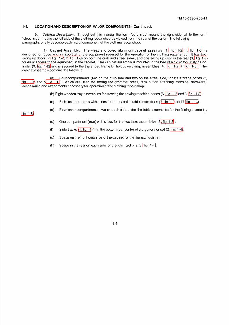
b. Detailed Description. Throughout this manual the term "curb side" means the right side, while the term"street side" means the left side of the clothing repair shop as viewed from the rear of the trailer. The followingparagraphs briefly describe each major component of the clothing repair shop.
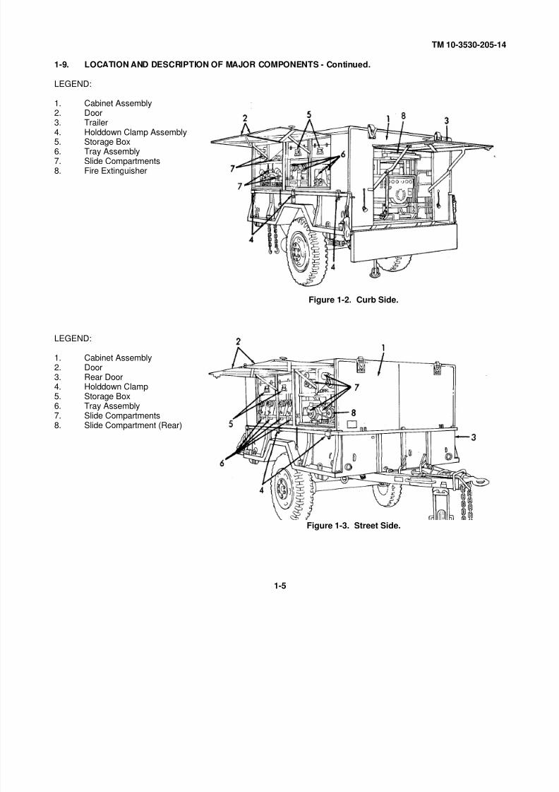
(1) Cabinet Assembly. The weather-proofed aluminum cabinet assembly (1, fig. 1-2; 1, fig. 1-3) isdesigned to house and transport all of the equipment required for the operation of the clothing repair shop. It has twoswing up doors (2, fig. 1-2 ; 2, fig. 1-3 ) on both the curb and street sides, and one swing up door in the rear (3, fig. 1-3)for easy access to the equipment in the cabinet. The cabinet assembly is mounted in the bed of a 1-1/2 ton utility cargotrailer (3, f ig. 1-2) and is secured to the trailer bed frame by holddown clamp assemblies (4, f ig. 1-2; 4, f ig. 1-3). Thecabinet assembly contains the following:
(a) Four compartments (two on the curb side and two on the street side) for the storage boxes (5,fig. 1-2 and 5 , fig. 1- 3), which are used for storing the grommet press, tack button attaching machine, hardware,accessories and attachments necessary for operation of the clothing repair shop.
(b) Eight wooden tray assemblies for stowing the sewing machine heads (6 , fig. 1-2 and 6, fig. 1-3) .
(c) Eight compartments with slides for the machine table assemblies ( 7, fig. 1-2 and 7, fig. 1-3) .
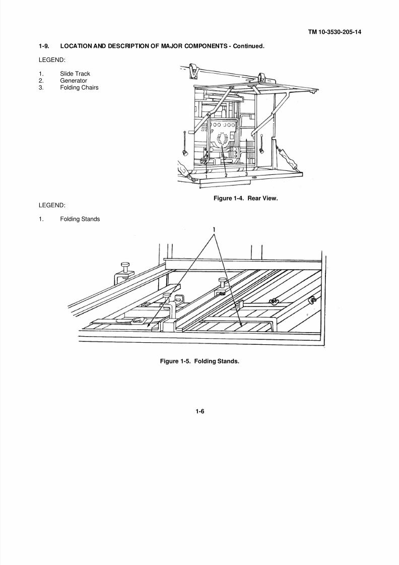
(d) Four lower compartments, two on each side under the table assemblies for the folding stands (1,fig. 1-5) .
(e) One compartment (rear) with slides for the two table assemblies (8 , fig. 1-3) .
(f) Slide tracks (1, fig. 1 -4) in the bottom rear center of the generator set (2, fig. 1-4) .
(g) Space on the front curb side of the cabinet for the fire extinguisher.
(h) Space in the rear on each side for the folding chairs (3, fig. 1-4) .
1-4
8/7/2019 TM 10-3530-205-10 CLOTHING REPAIR SHOP
http://slidepdf.com/reader/full/tm-10-3530-205-10-clothing-repair-shop 30/455
TM 10-3530-205-14
1-9. LOCATION AND DESCRIPTION OF MAJOR COMPONENTS - Continued.
LEGEND:
1. Cabinet Assembly2. Door3. Trailer4. Holddown Clamp Assembly5. Storage Box6. Tray Assembly7. Slide Compartments8. Fire Extinguisher
Figure 1-2. Curb Side.
LEGEND:
1. Cabinet Assembly2. Door3. Rear Door4. Holddown Clamp5. Storage Box6. Tray Assembly7. Slide Compartments8. Slide Compartment (Rear)
Figure 1-3. Street Side.
1-5
8/7/2019 TM 10-3530-205-10 CLOTHING REPAIR SHOP
http://slidepdf.com/reader/full/tm-10-3530-205-10-clothing-repair-shop 31/455
TM 10-3530-205-14
1-9. LOCATION AND DESCRIPTION OF MAJOR COMPONENTS - Continued.
LEGEND:
1. Slide Track2. Generator3. Folding Chairs
Figure 1-4. Rear View.LEGEND:
1. Folding Stands
Figure 1-5. Folding Stands.
1-6
8/7/2019 TM 10-3530-205-10 CLOTHING REPAIR SHOP
http://slidepdf.com/reader/full/tm-10-3530-205-10-clothing-repair-shop 32/455
TM 10-3530-205-14
1-9. LOCATION AND DESCRIPTION OF MAJOR COMPONENTS - Continued.
b. Detailed Description - Continued.
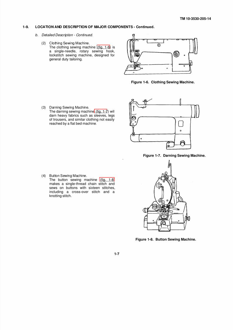
(2) Clothing Sewing Machine.The clothing sewing machine (fig. 1-6) isa single-needle, rotary sewing hook,lockstitch sewing machine, designed forgeneral duty tailoring.
(3) Darning Sewing Machine.The darning sewing machine (fig. 1-7 ) willdarn heavy fabrics such as sleeves, legsof trousers, and similar clothing not easilyreached by a flat bed machine.
(4) Button Sewing Machine.The button sewing machine (fig. 1-8)makes a single-thread chain stitch andsews on buttons with sixteen stitches,including a cross-over stitch and aknotting stitch.
Figure 1-8. Button Sewing Machine.
Figure 1-7. Darning Sewing Machine.
Figure 1-6. Clothing Sewing Machine.
1-7
8/7/2019 TM 10-3530-205-10 CLOTHING REPAIR SHOP
http://slidepdf.com/reader/full/tm-10-3530-205-10-clothing-repair-shop 33/455
TM 10-3530-205-14
1-9. LOCATION AND DESCRIPTION OF MAJOR COMPONENTS - Continued.
b. Detailed Description - Continued.
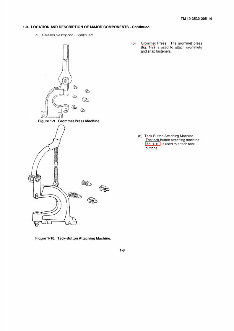
(5) Grommet Press. The grommet press(fig. 1-9) is used to attach grommetsand snap fasteners.
(6) Tack-Button Attaching Machine.The tack-button attaching machine(fig. 1-10) is used to attach tackbuttons.
Figure 1-10. Tack-Button Attaching Machine.
Figure 1-9. Grommet Press Machine.
1-8
8/7/2019 TM 10-3530-205-10 CLOTHING REPAIR SHOP
http://slidepdf.com/reader/full/tm-10-3530-205-10-clothing-repair-shop 34/455
TM 10-3530-205-14
1-10. E QUIPMENT DATA.
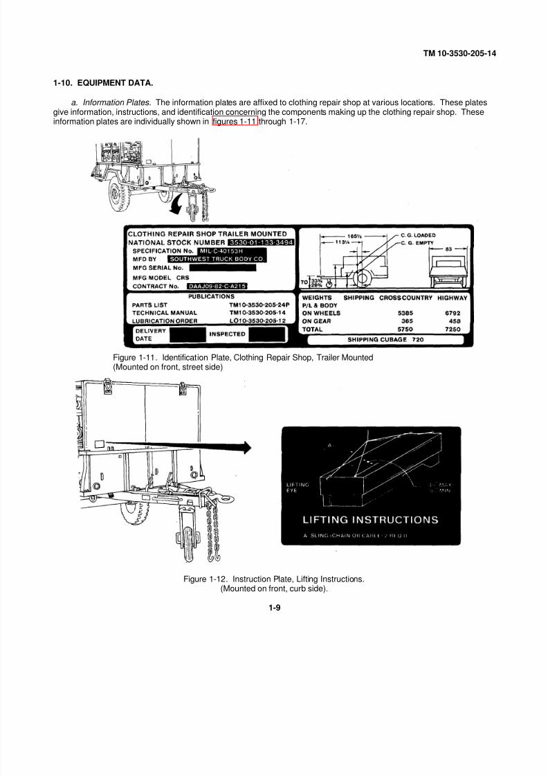
a. Information Plates. The information plates are affixed to clothing repair shop at various locations. These platesgive information, instructions, and identification concerning the components making up the clothing repair shop. These
information plates are individually shown in figures 1-11 through 1-17.
Figure 1-12 . Instruction Plate, Lifting Instructions.(Mounted on front, curb side).
1-9
Figure 1-11 . Identification Plate, Clothing Repair Shop, Trailer Mounted(Mounted on front, street side)
8/7/2019 TM 10-3530-205-10 CLOTHING REPAIR SHOP
http://slidepdf.com/reader/full/tm-10-3530-205-10-clothing-repair-shop 35/455
TM 10-3530-205-14
1-10. EQUIPMENT DATA - Continued.
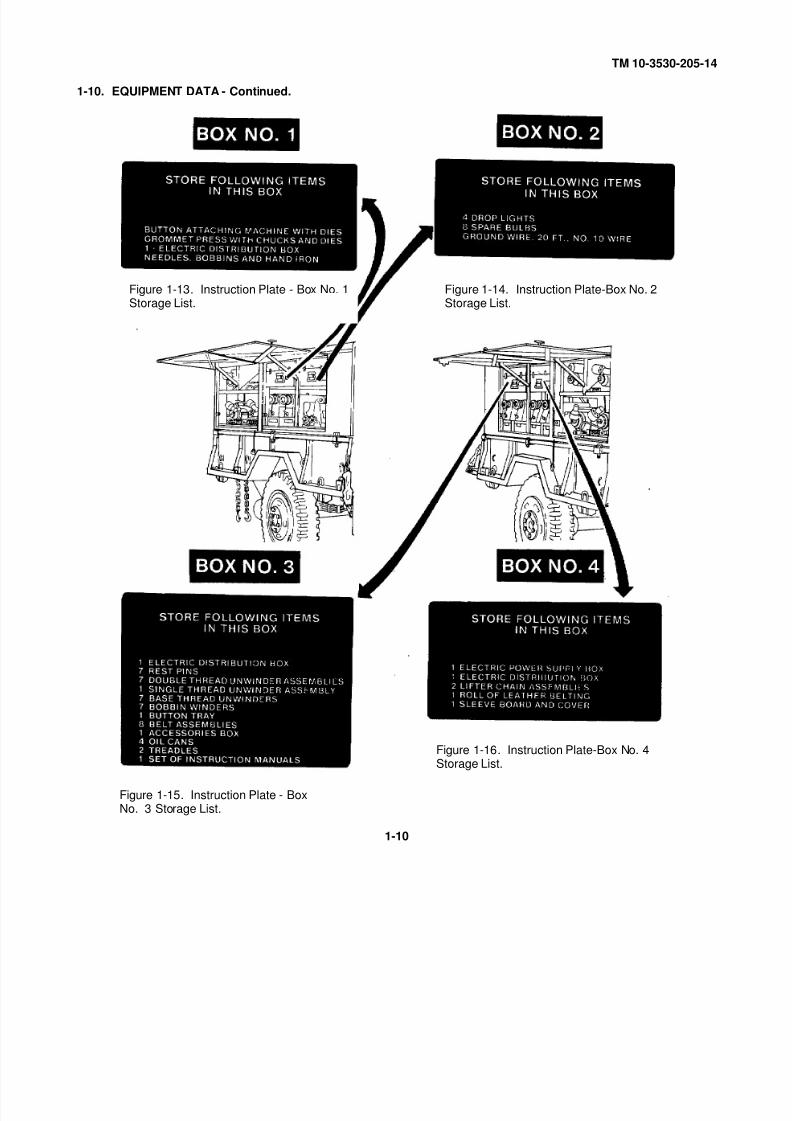
Figure 1-15 . Instruction Plate - BoxNo. 3 Storage List.
1-10
Figure 1-13 . Instruction Plate - Box No. 1Storage List.
Figure 1-14. Instruction Plate-Box No. 2Storage List.
Figure 1-16 . Instruction Plate-Box No. 4Storage List.
8/7/2019 TM 10-3530-205-10 CLOTHING REPAIR SHOP
http://slidepdf.com/reader/full/tm-10-3530-205-10-clothing-repair-shop 36/455
TM 10-3530-205-14
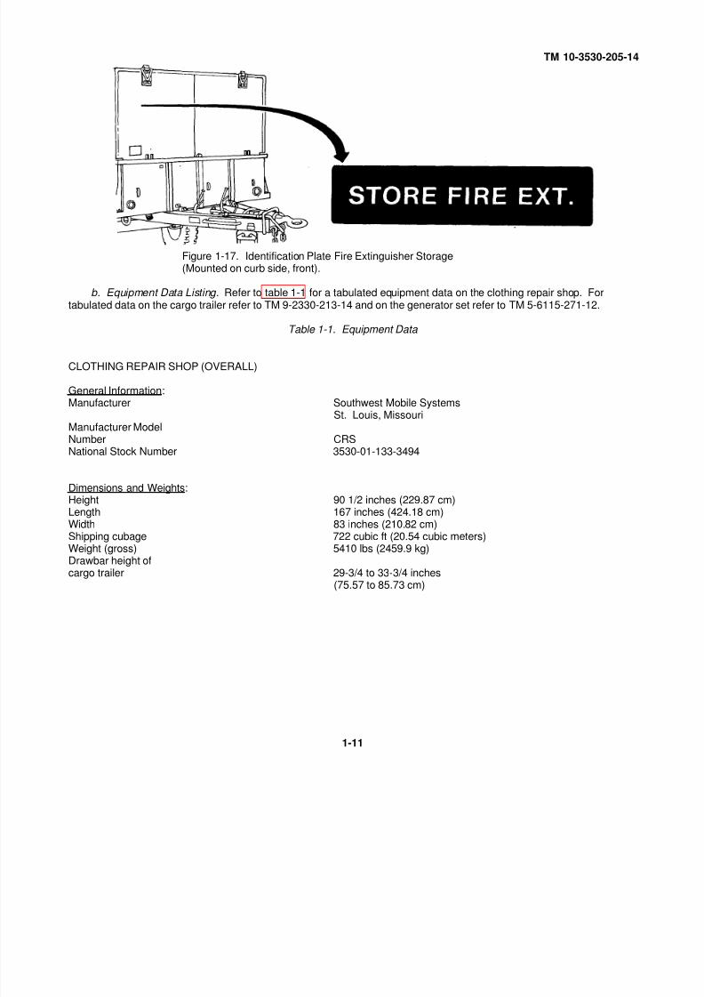
Figure 1-17. Identification Plate Fire Extinguisher Storage(Mounted on curb side, front).
b. Equipment Data Listing. Refer to table 1-1 for a tabulated equipment data on the clothing repair shop. Fortabulated data on the cargo trailer refer to TM 9-2330-213-14 and on the generator set refer to TM 5-6115-271-12.
Table 1-1. Equipment Data
CLOTHING REPAIR SHOP (OVERALL)
General Information:Manufacturer Southwest Mobile Systems
St. Louis, MissouriManufacturer ModelNumber CRSNational Stock Number 3530-01-133-3494
Dimensions and Weights:Height 90 1/2 inches (229.87 cm)Length 167 inches (424.18 cm)Width 83 inches (210.82 cm)Shipping cubage 722 cubic ft (20.54 cubic meters)Weight (gross) 5410 lbs (2459.9 kg)Drawbar height ofcargo trailer 29-3/4 to 33-3/4 inches
(75.57 to 85.73 cm)
1-11
8/7/2019 TM 10-3530-205-10 CLOTHING REPAIR SHOP
http://slidepdf.com/reader/full/tm-10-3530-205-10-clothing-repair-shop 37/455
TM 10-3530-205-14
1-10. EQUIPMENT DATA - Continued.
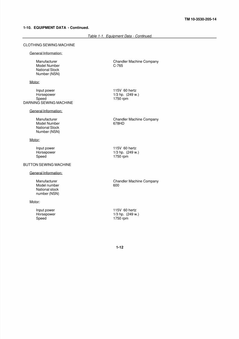
Table 1-1. Equipment Data - Continued.
CLOTHING SEWING MACHINE
General Information:Manufacturer Chandler Machine CompanyModel Number C-765National StockNumber (NSN)
Motor:
Input power 115V 60 hertzHorsepower 1/3 hp. (249 w.)Speed 1750 rpm
DARNING SEWING MACHINE
General Information:
Manufacturer Chandler Machine CompanyModel Number 678HDNational StockNumber (NSN)
Motor:
Input power 115V 60 hertzHorsepower 1/3 hp. (249 w.)Speed 1750 rpm
BUTTON SEWING MACHINE
General Information:
Manufacturer Chandler Machine CompanyModel number 600National stocknumber (NSN)
Motor:
Input power 115V 60 hertzHorsepower 1/3 hp. (249 w.)
Speed 1750 rpm
1-12
8/7/2019 TM 10-3530-205-10 CLOTHING REPAIR SHOP
http://slidepdf.com/reader/full/tm-10-3530-205-10-clothing-repair-shop 38/455
TM 10-3530-205-14
SECTION III. TECHNICAL PRINCIPLES OF OPERATION
Para. Para.Button Sewing Machine...................... ... 1-12 Grommet Press ................................ ............. .... 1-14Clothing Sewing Machine................... ... 1-11 Tack Button Attaching................................ ........Darning Machine................................ ... 1-13 Machine ................................ ........................ .... 1-15
1-11. C LOTHING SEWING MACHINE.
The clothing sewing machine is designed for stitching clothing, coats, suits, skirts, and shirts. Each time the arm shaftrotates, the rotary sewing hook catches the needle thread, loops it around the bobbin thread, and forms a lockstitch. Theclutch allows the operator to control the sewing speed.
1-12. B UTTON SEWING MACHINE.
The button sewing machine sews with needle thread only and has no bobbin. It is equipped with a vibrating needle barand clamp for sewing two and four hole flat buttons.
1-13. D ARNING MACHINE.
The darning machine uses a single-needle and rotary sewing hook to make a lockstitch. The presser foot goes up witheach stroke of the needle to allow the material to be moved freely in any direction while darning.
1-14. G ROMMET PRESS.
The grommet press is a small, hand-operated machine consisting of a metal frame that houses the plunger. The presscomes equipped with assorted sets of chucks and dies that are easily interchanged. The chucks are installed in theplunger and dies are installed in the lower portion. When the hand-lever is pushed down, the chuck presses upon thedie, molding the separate metal snap fastener parts into the finished fastener and attaching the fastener to the material.
1-15. T ACK-BUTTON ATTACHING MACHINE.
The tack-button attaching machine is a small, hand-operated machine consisting of a plunger housed in a metal frame.With a set of dies installed that match the tack-button, the handle is pushed down. The dies press upon the separatebutton parts into a finished tack button and attach the fastener to the material.
1-13 / 1-14 Blank
8/7/2019 TM 10-3530-205-10 CLOTHING REPAIR SHOP
http://slidepdf.com/reader/full/tm-10-3530-205-10-clothing-repair-shop 39/455
TM 10-3530-205-14
CHAPTER 2OPERATING INSTRUCTIONS
Section I. DESCRIPTION AND USE OF OPERATOR'S CONTROLS ANDINDICATORS
Section II. OPERATOR PREVENTIVE MAINTENANCE CHECKS ANDSERVICES (PMCS)Section III. OPERATION UNDER USUAL CONDITIONSSection IV. OPERATION UNDER UNUSUAL CONDITIONS
SECTION I. DESCRIPTION AND USE OF OPERATOR'SCONTROLS AND INDICATORS
Para. Para.Description and Use of General ................................ ........................ .... 2-1Controls and Indicators....................... ... 2-2
2-1. G ENERAL.This section describes, locates, and illustrates the controls and indicators for you. Enough information about the use ofthe various controls and indicators is given to help you get the best performance from the clothing repair shop sewingmachines. Unload and assemble the equipment in accordance with paragraph 2-9.
2-2. D ESCRIPTION AND USE OF CONTROLS AND INDICATORS.Tables 2-1 , 2-2, 2-3, and 2-4 describe the functional use and shows you the location of the controls and indicators on theclothing, darning, button sewing machines, and bobbin winder. These controls and indicators will allow you to get thebest performance from the machines if used properly. The "Key" number column in Tables 2-1 , 2-2, 2-3, and 2-4 tellsyou the number of the control or indicator you should look for in the illustration within a particular table. Refer to TM 5-6115-271-14 for information on the controls and indicators for the generator set and to TM 9-2330-213-14 for informationon the controls and indicators for the cargo trailer.
2-1
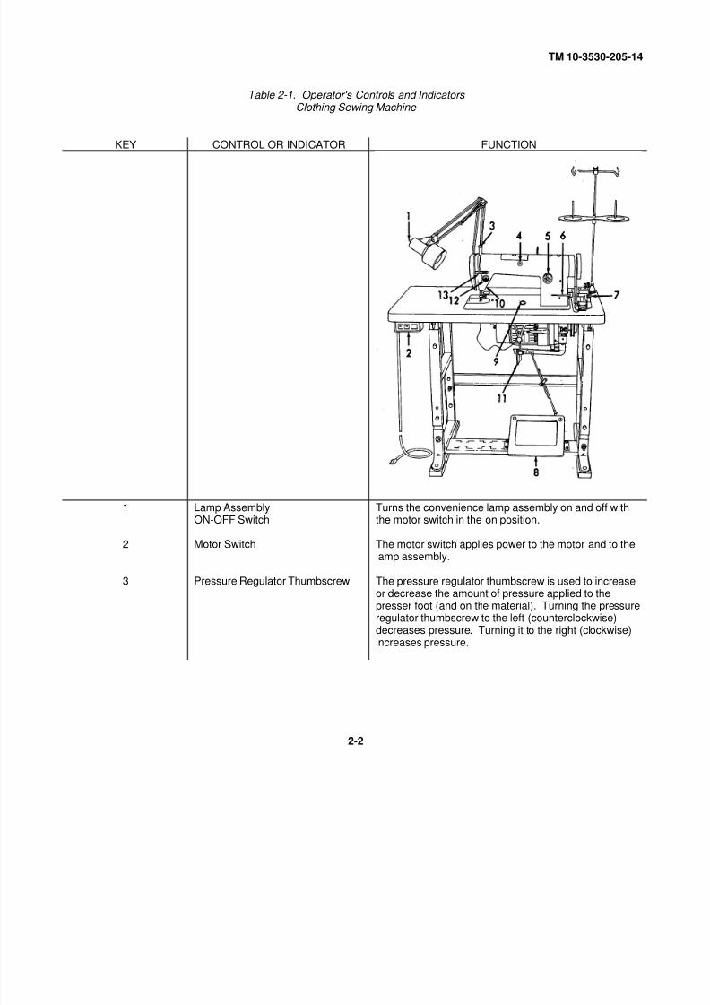
8/7/2019 TM 10-3530-205-10 CLOTHING REPAIR SHOP
http://slidepdf.com/reader/full/tm-10-3530-205-10-clothing-repair-shop 40/455
TM 10-3530-205-14
Table 2-1 . Operator's Controls and Indicators Clothing Sewing Machine
KEY CONTROL OR INDICATOR FUNCTION
1
2
3
Lamp AssemblyON-OFF Switch
Motor Switch
Pressure Regulator Thumbscrew
Turns the convenience lamp assembly on and off withthe motor switch in the on position.
The motor switch applies power to the motor and to thelamp assembly.
The pressure regulator thumbscrew is used to increaseor decrease the amount of pressure applied to thepresser foot (and on the material). Turning the pressureregulator thumbscrew to the left (counterclockwise)decreases pressure. Turning it to the right (clockwise)increases pressure.
2-2
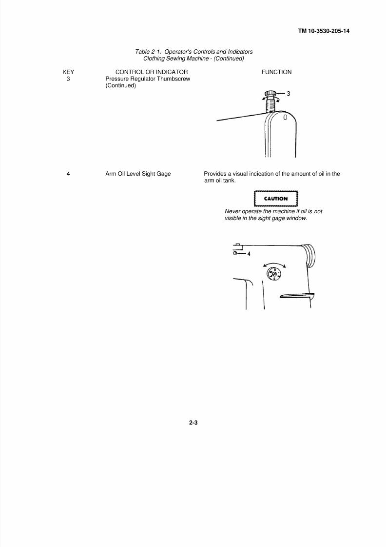
8/7/2019 TM 10-3530-205-10 CLOTHING REPAIR SHOP
http://slidepdf.com/reader/full/tm-10-3530-205-10-clothing-repair-shop 41/455
TM 10-3530-205-14
Table 2-1. Operator's Controls and Indicators Clothing Sewing Machine - (Continued)
KEY CONTROL OR INDICATOR FUNCTION3 Pressure Regulator Thumbscrew
(Continued)
4 Arm Oil Level Sight Gage Provides a visual indication of the amount of oil in thearm oil tank.
Never operate the machine if oil is not visible in the sight gage window.
2-3
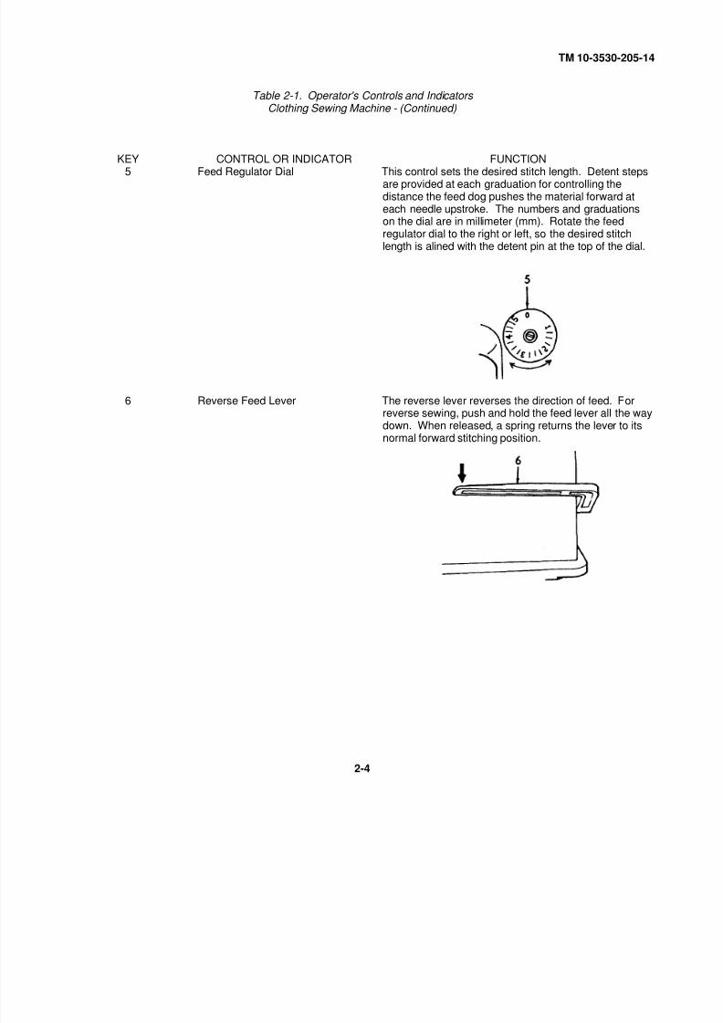
8/7/2019 TM 10-3530-205-10 CLOTHING REPAIR SHOP
http://slidepdf.com/reader/full/tm-10-3530-205-10-clothing-repair-shop 42/455
TM 10-3530-205-14
Table 2-1. Operator's Controls and Indicators Clothing Sewing Machine - (Continued)
KEY CONTROL OR INDICATOR FUNCTION5 Feed Regulator Dial This control sets the desired stitch length. Detent stepsare provided at each graduation for controlling thedistance the feed dog pushes the material forward ateach needle upstroke. The numbers and graduationson the dial are in millimeter (mm). Rotate the feedregulator dial to the right or left, so the desired stitchlength is alined with the detent pin at the top of the dial.
6 Reverse Feed Lever The reverse lever reverses the direction of feed. Forreverse sewing, push and hold the feed lever all the waydown. When released, a spring returns the lever to itsnormal forward stitching position.
2-4
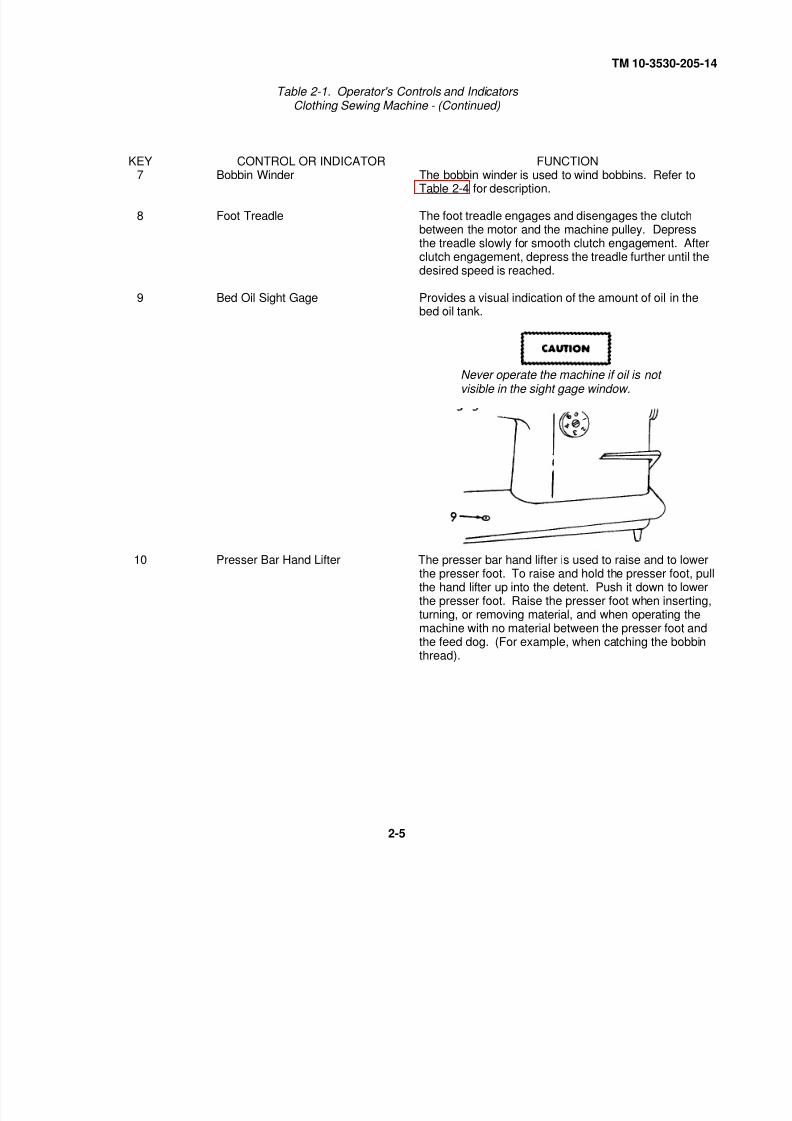
8/7/2019 TM 10-3530-205-10 CLOTHING REPAIR SHOP
http://slidepdf.com/reader/full/tm-10-3530-205-10-clothing-repair-shop 43/455
TM 10-3530-205-14
Table 2-1. Operator's Controls and Indicators Clothing Sewing Machine - (Continued)
KEY CONTROL OR INDICATOR FUNCTION
7
8
9
Bobbin Winder
Foot Treadle
Bed Oil Sight Gage
The bobbin winder is used to wind bobbins. Refer toTable 2-4 for description.
The foot treadle engages and disengages the clutchbetween the motor and the machine pulley. Depressthe treadle slowly for smooth clutch engagement. Afterclutch engagement, depress the treadle further until thedesired speed is reached.
Provides a visual indication of the amount of oil in thebed oil tank.
Never operate the machine if oil is not visible in the sight gage window.
10 Presser Bar Hand Lifter The presser bar hand lifter is used to raise and to lowerthe presser foot. To raise and hold the presser foot, pullthe hand lifter up into the detent. Push it down to lowerthe presser foot. Raise the presser foot when inserting,turning, or removing material, and when operating themachine with no material between the presser foot andthe feed dog. (For example, when catching the bobbinthread).
2-5
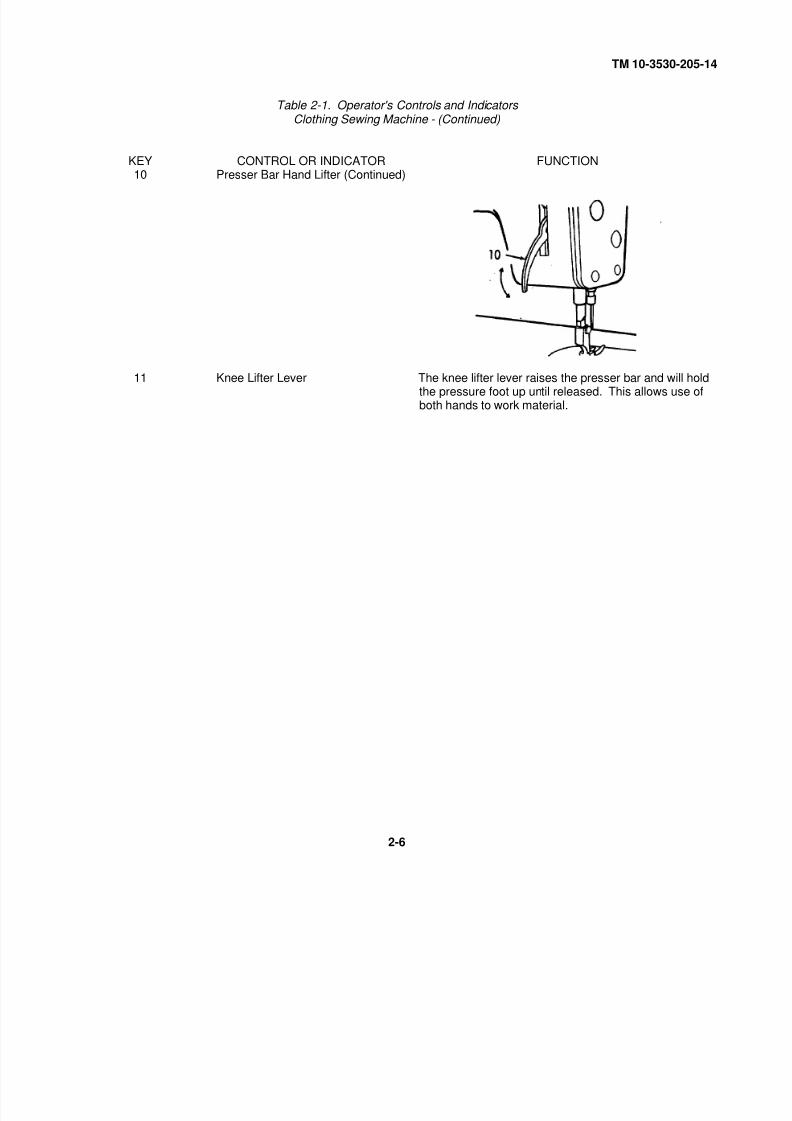
8/7/2019 TM 10-3530-205-10 CLOTHING REPAIR SHOP
http://slidepdf.com/reader/full/tm-10-3530-205-10-clothing-repair-shop 44/455
TM 10-3530-205-14
Table 2-1. Operator's Controls and Indicators Clothing Sewing Machine - (Continued)
KEY CONTROL OR INDICATOR FUNCTION
10 Presser Bar Hand Lifter (Continued)
11 Knee Lifter Lever The knee lifter lever raises the presser bar and will holdthe pressure foot up until released. This allows use ofboth hands to work material.
2-6
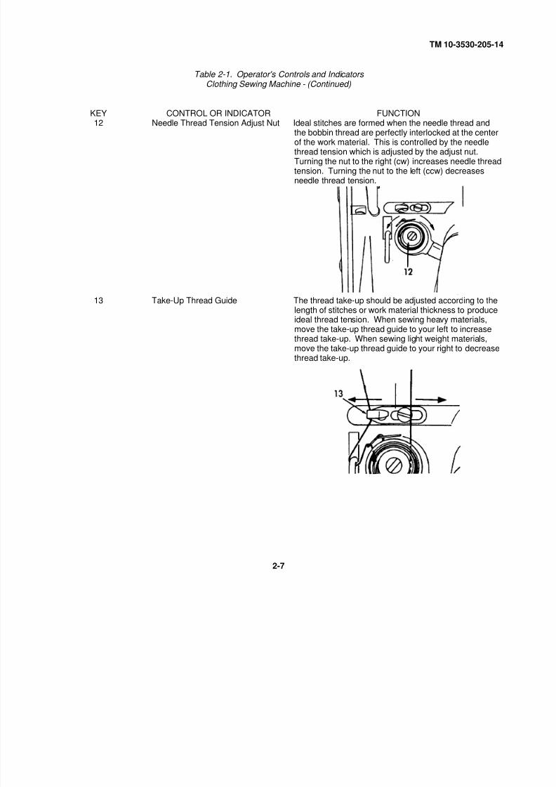
8/7/2019 TM 10-3530-205-10 CLOTHING REPAIR SHOP
http://slidepdf.com/reader/full/tm-10-3530-205-10-clothing-repair-shop 45/455
TM 10-3530-205-14
Table 2-1. Operator's Controls and Indicators Clothing Sewing Machine - (Continued)
KEY CONTROL OR INDICATOR FUNCTION
12 Needle Thread Tension Adjust Nut Ideal stitches are formed when the needle thread andthe bobbin thread are perfectly interlocked at the centerof the work material. This is controlled by the needlethread tension which is adjusted by the adjust nut.Turning the nut to the right (cw) increases needle threadtension. Turning the nut to the left (ccw) decreasesneedle thread tension.
13 Take-Up Thread Guide The thread take-up should be adjusted according to thelength of stitches or work material thickness to produceideal thread tension. When sewing heavy materials,move the take-up thread guide to your left to increasethread take-up. When sewing light weight materials,move the take-up thread guide to your right to decreasethread take-up.
2-7
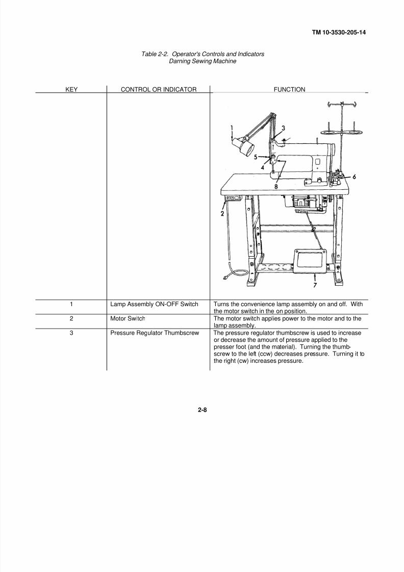
8/7/2019 TM 10-3530-205-10 CLOTHING REPAIR SHOP
http://slidepdf.com/reader/full/tm-10-3530-205-10-clothing-repair-shop 46/455
TM 10-3530-205-14
Table 2-2. Operator's Controls and Indicators Darning Sewing Machine
KEY CONTROL OR INDICATOR FUNCTION
1 Lamp Assembly ON-OFF Switch Turns the convenience lamp assembly on and off. Withthe motor switch in the on position.
2 Motor Switch The motor switch applies power to the motor and to thelamp assembly.
3 Pressure Regulator Thumbscrew The pressure regulator thumbscrew is used to increaseor decrease the amount of pressure applied to thepresser foot (and the material). Turning the thumb-screw to the left (ccw) decreases pressure. Turning it tothe right (cw) increases pressure.
2-8
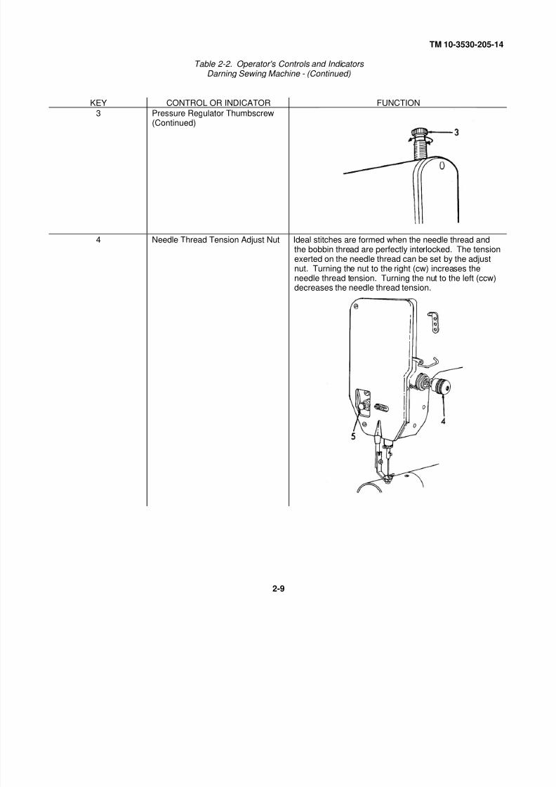
8/7/2019 TM 10-3530-205-10 CLOTHING REPAIR SHOP
http://slidepdf.com/reader/full/tm-10-3530-205-10-clothing-repair-shop 47/455
TM 10-3530-205-14
Table 2-2. Operator's Controls and Indicators Darning Sewing Machine - (Continued)
KEY CONTROL OR INDICATOR FUNCTION3 Pressure Regulator Thumbscrew
(Continued)
4 Needle Thread Tension Adjust Nut Ideal stitches are formed when the needle thread andthe bobbin thread are perfectly interlocked. The tensionexerted on the needle thread can be set by the adjustnut. Turning the nut to the right (cw) increases theneedle thread tension. Turning the nut to the left (ccw)decreases the needle thread tension.
2-9
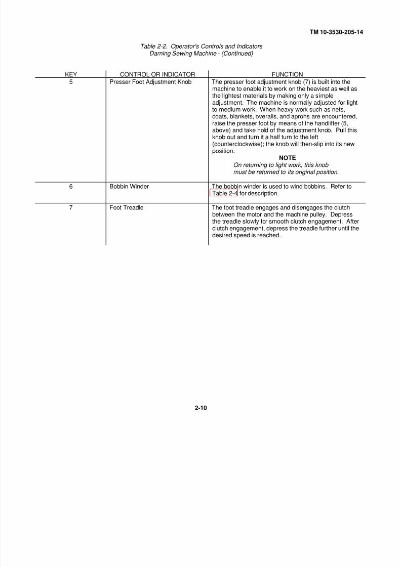
8/7/2019 TM 10-3530-205-10 CLOTHING REPAIR SHOP
http://slidepdf.com/reader/full/tm-10-3530-205-10-clothing-repair-shop 48/455
TM 10-3530-205-14
Table 2-2. Operator's Controls and Indicators Darning Sewing Machine - (Continued)
KEY CONTROL OR INDICATOR FUNCTION5 Presser Foot Adjustment Knob The presser foot adjustment knob (7) is built into the
machine to enable it to work on the heaviest as well asthe lightest materials by making only a simpleadjustment. The machine is normally adjusted for lightto medium work. When heavy work such as nets,coats, blankets, overalls, and aprons are encountered,raise the presser foot by means of the handlifter (5,above) and take hold of the adjustment knob. Pull thisknob out and turn it a half turn to the left(counterclockwise); the knob will then-slip into its newposition.
NOTEOn returning to light work, this knob must be returned to its original position.
6 Bobbin Winder The bobbin winder is used to wind bobbins. Refer toTable 2-4 for description.
7 Foot Treadle The foot treadle engages and disengages the clutchbetween the motor and the machine pulley. Depressthe treadle slowly for smooth clutch engagement. Afterclutch engagement, depress the treadle further until thedesired speed is reached.
2-10
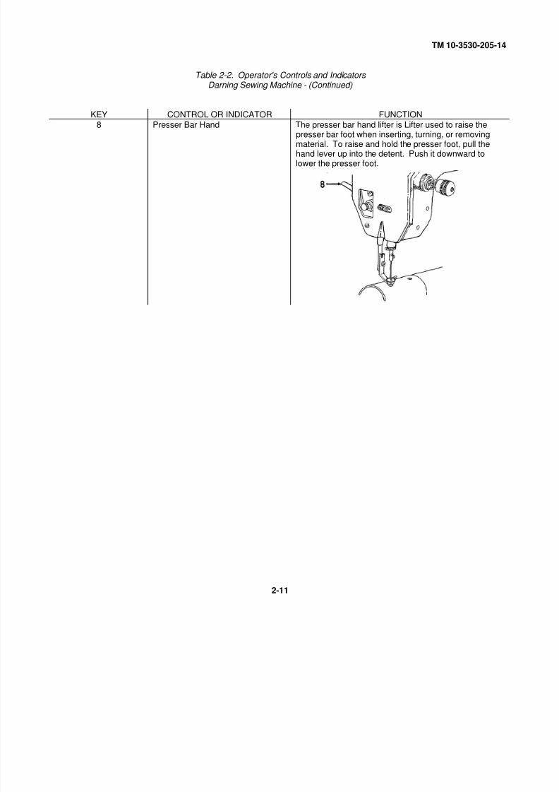
8/7/2019 TM 10-3530-205-10 CLOTHING REPAIR SHOP
http://slidepdf.com/reader/full/tm-10-3530-205-10-clothing-repair-shop 49/455
TM 10-3530-205-14
Table 2-2. Operator's Controls and Indicators Darning Sewing Machine - (Continued)
KEY CONTROL OR INDICATOR FUNCTION
8 Presser Bar Hand The presser bar hand lifter is Lifter used to raise thepresser bar foot when inserting, turning, or removingmaterial. To raise and hold the presser foot, pull thehand lever up into the detent. Push it downward tolower the presser foot.
2-11
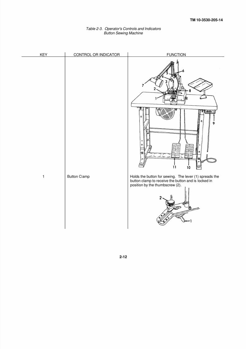
8/7/2019 TM 10-3530-205-10 CLOTHING REPAIR SHOP
http://slidepdf.com/reader/full/tm-10-3530-205-10-clothing-repair-shop 50/455
TM 10-3530-205-14
Table 2-3. Operator's Controls and Indicators Button Sewing Machine
KEY CONTROL OR INDICATOR FUNCTION
1 Button Clamp Holds the button for sewing. The lever (1) spreads thebutton clamp to receive the button and is locked inposition by the thumbscrew (2).
2-12
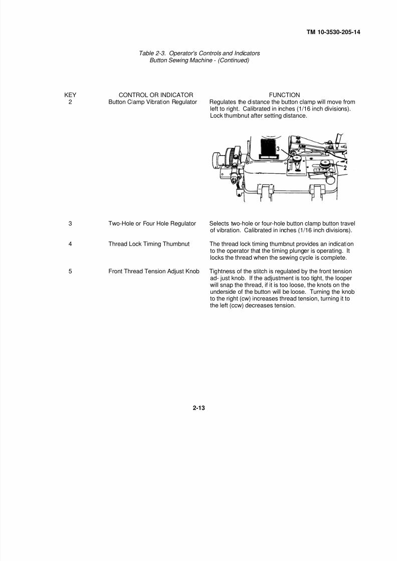
8/7/2019 TM 10-3530-205-10 CLOTHING REPAIR SHOP
http://slidepdf.com/reader/full/tm-10-3530-205-10-clothing-repair-shop 51/455
TM 10-3530-205-14
Table 2-3. Operator's Controls and Indicators Button Sewing Machine - (Continued)
KEY CONTROL OR INDICATOR FUNCTION2 Button Clamp Vibration Regulator Regulates the distance the button clamp will move from
left to right. Calibrated in inches (1/16 inch divisions).Lock thumbnut after setting distance.
3 Two-Hole or Four Hole Regulator Selects two-hole or four-hole button clamp button travelof vibration. Calibrated in inches (1/16 inch divisions).
4 Thread Lock Timing Thumbnut The thread lock timing thumbnut provides an indicationto the operator that the timing plunger is operating. Itlocks the thread when the sewing cycle is complete.
5 Front Thread Tension Adjust Knob Tightness of the stitch is regulated by the front tensionad- just knob. If the adjustment is too tight, the looperwill snap the thread, if it is too loose, the knots on theunderside of the button will be loose. Turning the knobto the right (cw) increases thread tension, turning it tothe left (ccw) decreases tension.
2-13
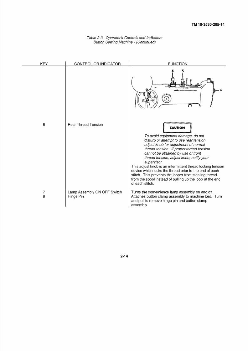
8/7/2019 TM 10-3530-205-10 CLOTHING REPAIR SHOP
http://slidepdf.com/reader/full/tm-10-3530-205-10-clothing-repair-shop 52/455
TM 10-3530-205-14
Table 2-3. Operator's Controls and Indicators Button Sewing Machine - (Continued)
KEY CONTROL OR INDICATOR FUNCTION
6 Rear Thread Tension
To avoid equipment damage, do not disturb or attempt to use rear tension adjust knob for adjustment of normal thread tension. If proper thread tension cannot be obtained by use of front thread tension, adjust knob, notify your supervisor.
This adjust knob is an intermittent thread locking tensiondevice which locks the thread prior to the end of eachstitch. This prevents the looper from stealing threadfrom the spool instead of pulling up the loop at the endof each stitch.
7 Lamp Assembly ON OFF Switch Turns the convenience lamp assembly on and off.8 Hinge Pin Attaches button clamp assembly to machine bed. Turn
and pull to remove hinge pin and button clampassembly.
2-14
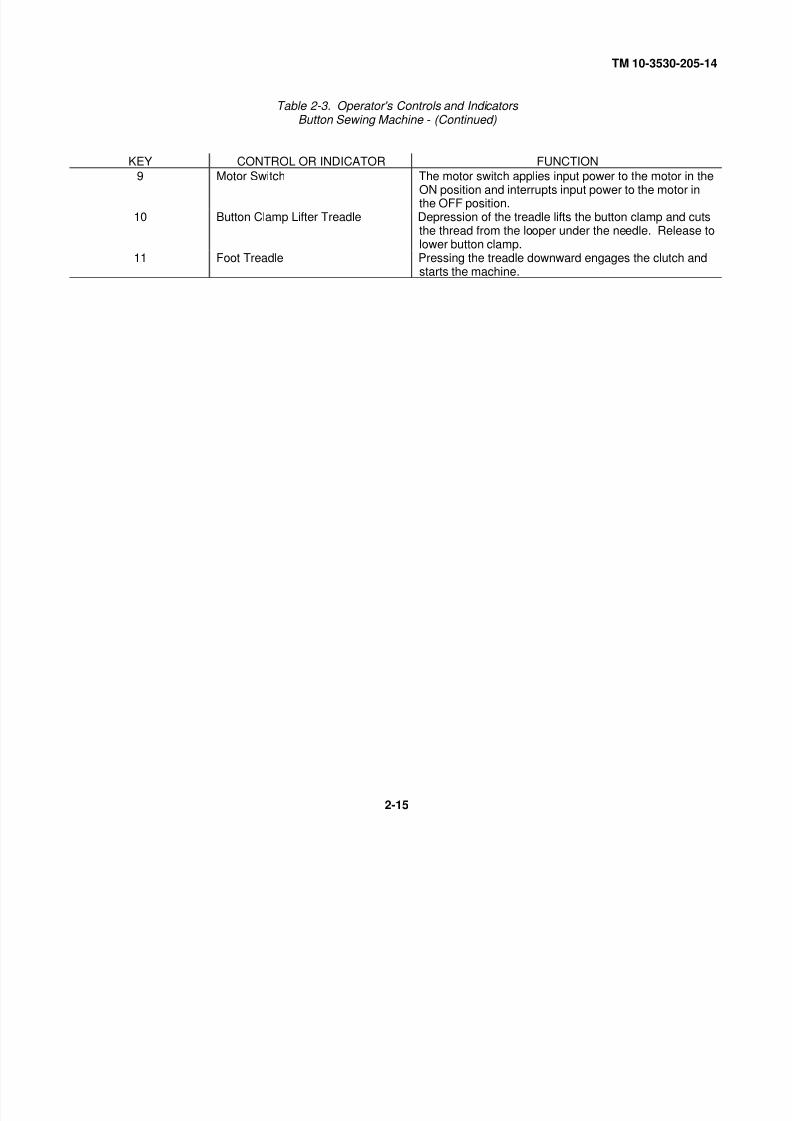
8/7/2019 TM 10-3530-205-10 CLOTHING REPAIR SHOP
http://slidepdf.com/reader/full/tm-10-3530-205-10-clothing-repair-shop 53/455
TM 10-3530-205-14
Table 2-3. Operator's Controls and Indicators Button Sewing Machine - (Continued)
KEY CONTROL OR INDICATOR FUNCTION
9 Motor Switch The motor switch applies input power to the motor in theON position and interrupts input power to the motor inthe OFF position.
10 Button Clamp Lifter Treadle Depression of the treadle lifts the button clamp and cutsthe thread from the looper under the needle. Release tolower button clamp.
11 Foot Treadle Pressing the treadle downward engages the clutch andstarts the machine.
2-15
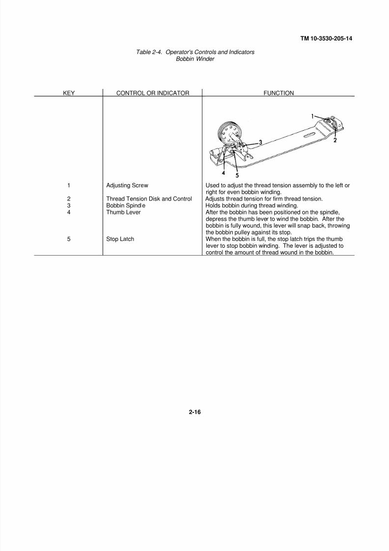
8/7/2019 TM 10-3530-205-10 CLOTHING REPAIR SHOP
http://slidepdf.com/reader/full/tm-10-3530-205-10-clothing-repair-shop 54/455
TM 10-3530-205-14
Table 2-4. Operator's Controls and Indicators Bobbin Winder
KEY CONTROL OR INDICATOR FUNCTION
1 Adjusting Screw Used to adjust the thread tension assembly to the left orright for even bobbin winding.
2 Thread Tension Disk and Control Adjusts thread tension for firm thread tension.3 Bobbin Spindle Holds bobbin during thread winding.4 Thumb Lever After the bobbin has been positioned on the spindle,
depress the thumb lever to wind the bobbin. After thebobbin is fully wound, this lever will snap back, throwingthe bobbin pulley against its stop.
5 Stop Latch When the bobbin is full, the stop latch trips the thumblever to stop bobbin winding. The lever is adjusted tocontrol the amount of thread wound in the bobbin.
2-16
8/7/2019 TM 10-3530-205-10 CLOTHING REPAIR SHOP
http://slidepdf.com/reader/full/tm-10-3530-205-10-clothing-repair-shop 55/455
TM 10-3530-205-14
SECTION II. OPERATOR PREVENTIVE MAINTENANCECHECKS AND SERVICES (PMCS)
Para. Para.
General................................ .............. ..... 2-3 Operator's PMCSProcedure................................ ........................ .... 2-4
2-3. G ENERAL.
a. Make sure that the equipment of the clothing repair shop is ready for operation at all times. It must beinspected systematically so defects may be discovered and corrected before they result in serious damage orfailure. The necessary preventive maintenance checks and services (PMCS) that are to be performed by theoperator are listed and described in table2-5.
b. Refer to TM 5-6115-271-14 for information on the preventive maintenance checks and services (PMCS) forthe generator set and to TM 9-2330- 213-14 for information on the preventive maintenance checks and services
(PMCS) for the cargo trailer.c. Do your Before (B) PREVENTIVE MAINTENANCE just before you operate. Pay attention to theWARNINGS and CAUTIONS.
d. Do your During (D) PREVENTIVE MAINTENANCE during operation. (During operation means to monitorthe clothing repair shop and its components while they are actually being used). Pay attention to theWARNINGS and CAUTIONS.
e. Do your After (A) PREVENTIVE MAINTENANCE right after operation. Pay attention to the WARNINGS andCAUTIONS.
f. If something doesn't work, troubleshoot it with the instructions in this manual and notify your supervisor.
g. Always do your PREVENTIVE MAINTENANCE in the same order so it gets to be a habit. Once you've hadsome practice, you'll spot anything wrong in a hurry.
h. If anything looks wrong and you can't fix it, write it on the DA Form 2404. If you find something seriouslywrong, report it to organizational maintenance RIGHT NOW.
i. If your equipment fails to operate, troubleshoot with proper equipment. Report any deficiencies using theproper forms. See DA PAM 738-750.
2-17
8/7/2019 TM 10-3530-205-10 CLOTHING REPAIR SHOP
http://slidepdf.com/reader/full/tm-10-3530-205-10-clothing-repair-shop 56/455
TM 10-3530-205-14
2-3. GENERAL - Continued.
j. When you do your PREVENTIVE MAINTENANCE, always take along the tools you'll need to make all thechecks. You'll always need a rag or two.
WARNING
Cleaning solvent, Federal Specification P-D-680, is both toxic and flammable. Keep off skin.Use only in a well-ventilated area and avoid prolonged breathing of vapors. Keep away from open flame.
(1) Keep it clean: Dirt, grease, oil, and debris only get in the way and may cover up a serious problem.Clean as you work and as needed. Use cleaning solven t (Appendix E , item 2) on all metal surfaces.Use soap and water when you clean cloth, rubber, or plastic material.
(2) Bolts, nuts, and screws: Check them all for obvious looseness, missing, bent, or broken condition.You can't try them all with a tool, of course, but look for chipped paint, bare metal, or rust around thebolt and nut heads. If you find one you think is loose, tighten it, or report it to organizationalmaintenance if you can't tighten it.
(3) Welds: Look for loose or chipped paint, rust, or gaps where parts are welded to together. If you find abad weld, report it to organizational maintenance.
(4) Electric wires and connectors: Look for cracked or broken insulators, bare wires, and loose or brokenconnectors. Tighten loose connectors and make sure the wires are in good shape.
2-4. O PERATOR PMCS PROCEDURES.a. Purpose. Your Preventive Maintenance Checks and Services table lists the inspections and care of yourequipment required to keep it in good operating condition.
b. Interval Column. The interval column tells you when to perform a certain check or service.
c. Procedure Column. The procedure column of your PMCS table tells you how to do the required checks andservices. Carefully follow these instructions. If you do not have the tools, or if the procedure tells you to, haveOrganizational Maintenance do the work.
2-18
8/7/2019 TM 10-3530-205-10 CLOTHING REPAIR SHOP
http://slidepdf.com/reader/full/tm-10-3530-205-10-clothing-repair-shop 57/455
TM 10-3530-205-14
2-4. OPERATOR PMCS PROCEDURES - Continued.
d. Reporting or Correcting Deficiencies. If your equipment does not perform as required, refer toChapter 3 under Troubleshooting for possible problems. Report any malfunctions or failures on theproper DA Form 2404, or refer to DA PAM 738-750.
e. Equipment is not ready/available if:. This column tells you when and why your equipment cannot beused.
NOTE
The terms ready/available and mission capable refer to the same status: Equipment is on hand and is able to perform its combat missions (See DA PAM 738-750).
2-19
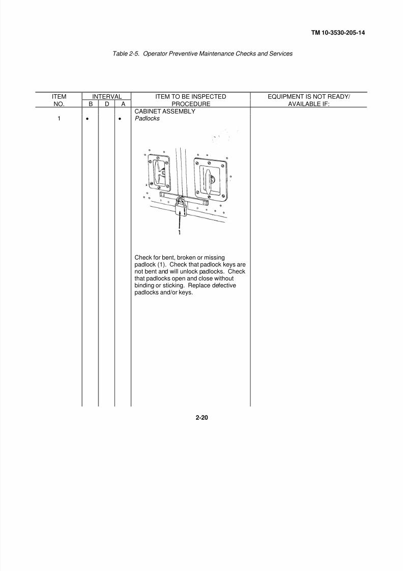
8/7/2019 TM 10-3530-205-10 CLOTHING REPAIR SHOP
http://slidepdf.com/reader/full/tm-10-3530-205-10-clothing-repair-shop 58/455
TM 10-3530-205-14
Table 2-5. Operator Preventive Maintenance Checks and Services
ITEM INTERVAL ITEM TO BE INSPECTED EQUIPMENT IS NOT READY/ NO. B D A PROCEDURE AVAILABLE IF:
CABINET ASSEMBLY1 • • Padlocks
Check for bent, broken or missingpadlock (1). Check that padlock keys arenot bent and will unlock padlocks. Checkthat padlocks open and close withoutbinding or sticking. Replace defectivepadlocks and/or keys.
2-20
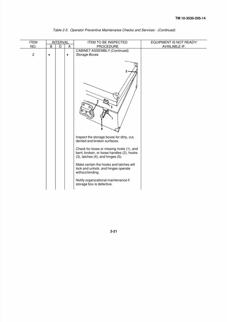
8/7/2019 TM 10-3530-205-10 CLOTHING REPAIR SHOP
http://slidepdf.com/reader/full/tm-10-3530-205-10-clothing-repair-shop 59/455
TM 10-3530-205-14
Table 2-5. Operator Preventive Maintenance Checks and Services - (Continued)
ITEM INTERVAL ITEM TO BE INSPECTED EQUIPMENT IS NOT READY/ NO. B D A PROCEDURE AVAILABLE IF:
CABINET ASSEMBLY (Continued)2 • • Storage Boxes
Inspect the storage boxes for dirty, cut,dented and broken surfaces.
Check for loose or missing rivets (1), andbent, broken, or loose handles (2), hooks(3), latches (4), and hinges (5).
Make certain the hooks and latches willlock and unlock, and hinges operatewithout binding.
Notify organizational maintenance ifstorage box is defective.
2-21
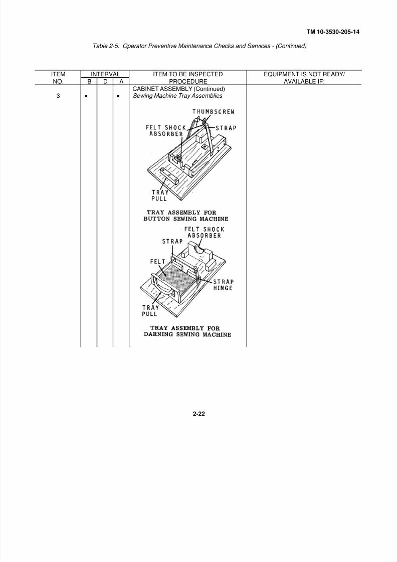
8/7/2019 TM 10-3530-205-10 CLOTHING REPAIR SHOP
http://slidepdf.com/reader/full/tm-10-3530-205-10-clothing-repair-shop 60/455
TM 10-3530-205-14
Table 2-5. Operator Preventive Maintenance Checks and Services - (Continued)
ITEM INTERVAL ITEM TO BE INSPECTED EQUIPMENT IS NOT READY/ NO. B D A PROCEDURE AVAILABLE IF:
CABINET ASSEMBLY (Continued)3 • • Sewing Machine Tray Assemblies
2-22
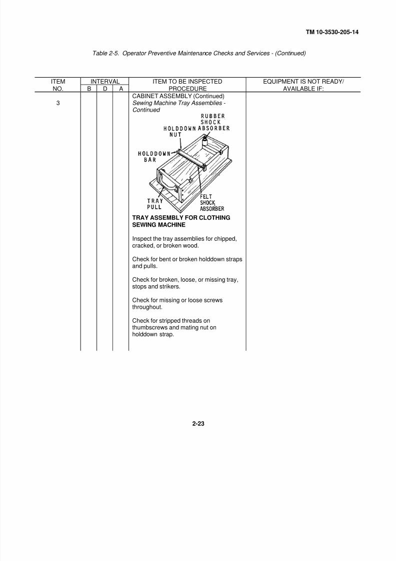
8/7/2019 TM 10-3530-205-10 CLOTHING REPAIR SHOP
http://slidepdf.com/reader/full/tm-10-3530-205-10-clothing-repair-shop 61/455
TM 10-3530-205-14
Table 2-5. Operator Preventive Maintenance Checks and Services - (Continued)
ITEM INTERVAL ITEM TO BE INSPECTED EQUIPMENT IS NOT READY/
NO. B D A PROCEDURE AVAILABLE IF:CABINET ASSEMBLY (Continued)3 Sewing Machine Tray Assemblies -
Continued
TRAY ASSEMBLY FOR CLOTHINGSEWING MACHINE
Inspect the tray assemblies for chipped,cracked, or broken wood.
Check for bent or broken holddown strapsand pulls.
Check for broken, loose, or missing tray,stops and strikers.
Check for missing or loose screwsthroughout.
Check for stripped threads onthumbscrews and mating nut onholddown strap.
2-23
8/7/2019 TM 10-3530-205-10 CLOTHING REPAIR SHOP
http://slidepdf.com/reader/full/tm-10-3530-205-10-clothing-repair-shop 62/455
TM 10-3530-205-14
Table 2-5. Operator Preventive Maintenance Checks and Services - (Continued)
ITEM INTERVAL ITEM TO BE INSPECTED EQUIPMENT IS NOT READY/
NO. B D A PROCEDURE AVAILABLE IF:CABINET ASSEMBLY (Continued)3 Sewing Machine Tray Assemblies -
Continued
Check for mechanical binding ofholddown strap hinges and check forloose or missing screws.
Check loose or torn felt shock absorbersand for worn or deteriorated bumpers.
Notify organizational maintenance of adefective tray assembly.
2-24
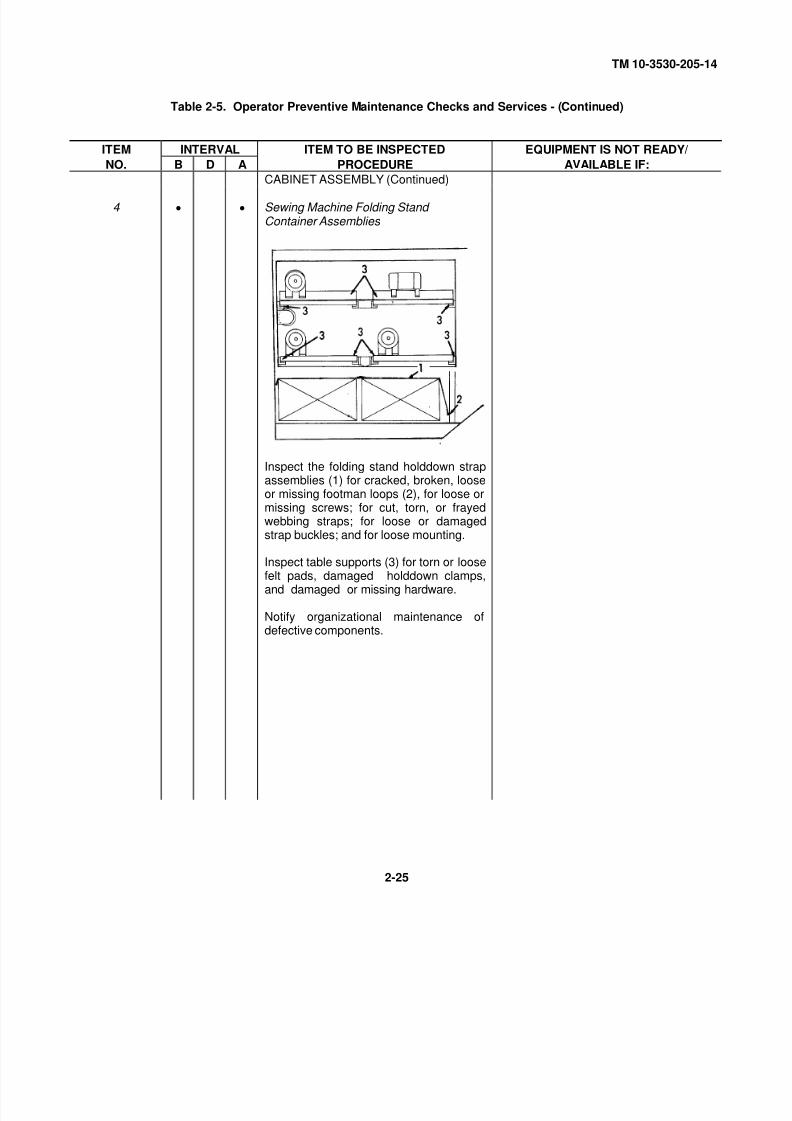
8/7/2019 TM 10-3530-205-10 CLOTHING REPAIR SHOP
http://slidepdf.com/reader/full/tm-10-3530-205-10-clothing-repair-shop 63/455
TM 10-3530-205-14
Table 2-5. Operator Preventive Maintenance Checks and Services - (Continued)
ITEM INTERVAL ITEM TO BE INSPECTED EQUIPMENT IS NOT READY/NO. B D A PROCEDURE AVAILABLE IF:
CABINET ASSEMBLY (Continued)
4 • • Sewing Machine Folding Stand Container Assemblies
Inspect the folding stand holddown strapassemblies (1) for cracked, broken, looseor missing footman loops (2), for loose ormissing screws; for cut, torn, or frayedwebbing straps; for loose or damagedstrap buckles; and for loose mounting.
Inspect table supports (3) for torn or loosefelt pads, damaged holddown clamps,and damaged or missing hardware.
Notify organizational maintenance ofdefective components.
2-25
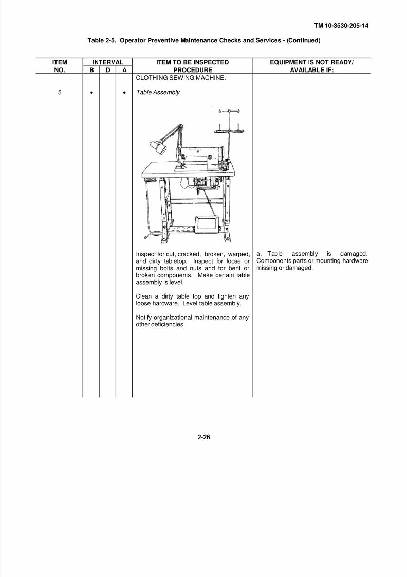
8/7/2019 TM 10-3530-205-10 CLOTHING REPAIR SHOP
http://slidepdf.com/reader/full/tm-10-3530-205-10-clothing-repair-shop 64/455
TM 10-3530-205-14
Table 2-5. Operator Preventive Maintenance Checks and Services - (Continued)
ITEM INTERVAL ITEM TO BE INSPECTED EQUIPMENT IS NOT READY/NO. B D A PROCEDURE AVAILABLE IF:
CLOTHING SEWING MACHINE.
5 • • Table Assembly
Inspect for cut, cracked, broken, warped,and dirty tabletop. Inspect for loose ormissing bolts and nuts and for bent orbroken components. Make certain tableassembly is level.
Clean a dirty table top and tighten anyloose hardware. Level table assembly.
Notify organizational maintenance of anyother deficiencies.
a. Table assembly is damaged.Components parts or mounting hardwaremissing or damaged.
2-26
8/7/2019 TM 10-3530-205-10 CLOTHING REPAIR SHOP
http://slidepdf.com/reader/full/tm-10-3530-205-10-clothing-repair-shop 65/455
TM 10-3530-205-14
Table 2-5. Operator Preventive Maintenance Checks and Services - (Continued)
ITEM INTERVAL ITEM TO BE INSPECTED EQUIPMENT IS NOT READY/NO. B D A PROCEDURE AVAILABLE IF:
CLOTHING SEWING MACHINE
(Continued).
6
7
•
• •
•
•
Knee Lifter
Inspect for loose mounting and for bent orbroken knee lifter. Make certain the lifterraises and lowers the presser foot.
Notify organizational maintenance of anydeficiencies.
Machine Service
a. Inspect the sewing machine for dirt,lint, and other debris.
b. Inspect for proper adjustments andoperation (para. 2-12) .
b. Sewing machine is out of adjustmentor fails to operate.
2-27
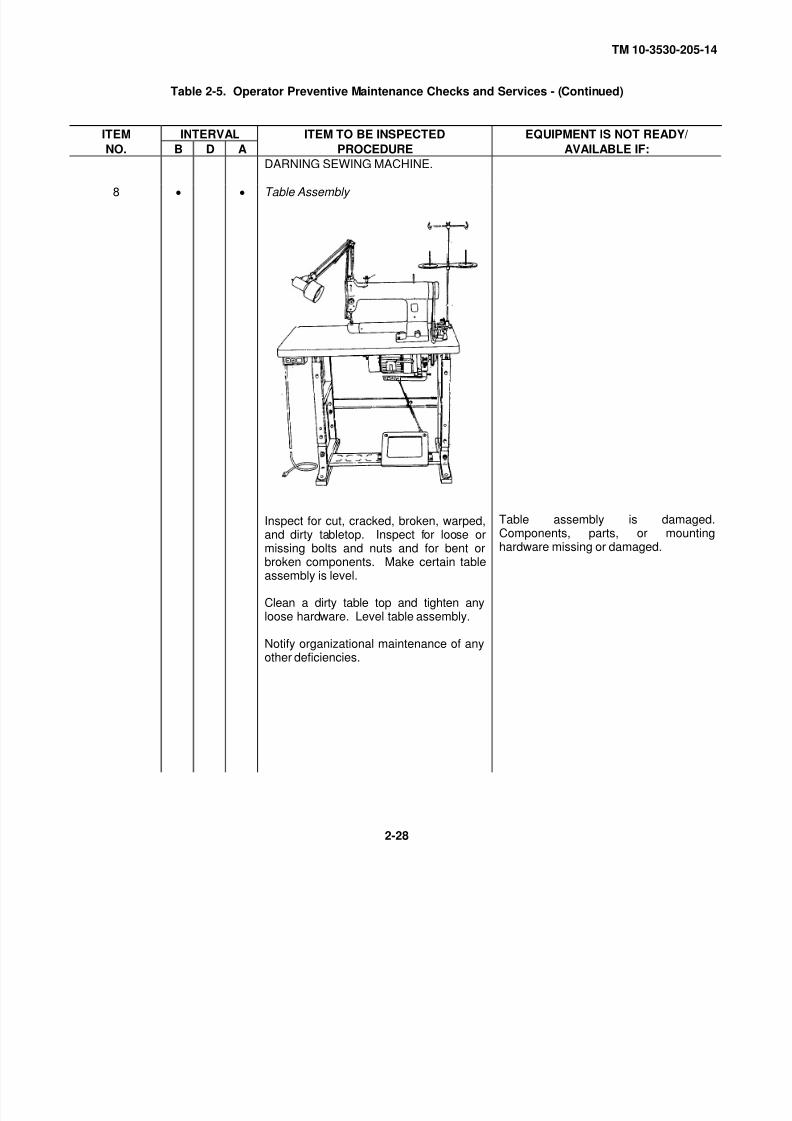
8/7/2019 TM 10-3530-205-10 CLOTHING REPAIR SHOP
http://slidepdf.com/reader/full/tm-10-3530-205-10-clothing-repair-shop 66/455
TM 10-3530-205-14
Table 2-5. Operator Preventive Maintenance Checks and Services - (Continued)
ITEM INTERVAL ITEM TO BE INSPECTED EQUIPMENT IS NOT READY/NO. B D A PROCEDURE AVAILABLE IF:
DARNING SEWING MACHINE.
8 • • Table Assembly
Inspect for cut, cracked, broken, warped,and dirty tabletop. Inspect for loose ormissing bolts and nuts and for bent orbroken components. Make certain tableassembly is level.
Clean a dirty table top and tighten anyloose hardware. Level table assembly.
Notify organizational maintenance of anyother deficiencies.
Table assembly is damaged.Components, parts, or mountinghardware missing or damaged.
2-28
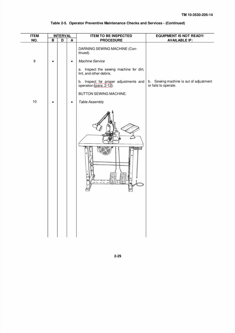
8/7/2019 TM 10-3530-205-10 CLOTHING REPAIR SHOP
http://slidepdf.com/reader/full/tm-10-3530-205-10-clothing-repair-shop 67/455
8/7/2019 TM 10-3530-205-10 CLOTHING REPAIR SHOP
http://slidepdf.com/reader/full/tm-10-3530-205-10-clothing-repair-shop 68/455
TM 10-3530-205-14
Table 2-5. Operator Preventive Maintenance Checks and Services - (Continued)
ITEM INTERVAL ITEM TO BE INSPECTED EQUIPMENT IS NOT READY/NO. B D A PROCEDURE AVAILABLE IF:
10
11 • •
BUTTON SEWING MACHINE (Con-tinued).
Table Assembly - Continued
Inspect for cut, cracked, broken, warped,and dirty tabletop. Inspect for loose ormissing bolts and nuts and for bent orbroken components. Make certain tableassembly is level.
Clean a dirty table top and tighten anyloose hardware. Level table assembly.
Notify organizational maintenance of anyother deficiencies.
Machine Service
a. Inspect the sewing machine for dirt,lint, and other debris.
b. Inspect for proper adjustments andoperation (para. 2-12) .
Table assembly is damaged.Components, parts, or mountinghardware missing or damaged.
b. Sewing machine is out of adjustmentor fails to operate.
2-30
8/7/2019 TM 10-3530-205-10 CLOTHING REPAIR SHOP
http://slidepdf.com/reader/full/tm-10-3530-205-10-clothing-repair-shop 69/455
TM 10-3530-205-14
SECTION III. OPERATION UNDER USUAL CONDITIONS
Para.Disconnecting Trailer from
Towing Vehicle ................................ ........ .... 2-8
General................................ .......................... .... 2-5Operating Instructions................................ .... ....2-10Operating Instructions for
Button Sewing Machine ........................... .... 2-14Operating Instructions for
Clothing Sewing Machine......................... .... 2-12Operating Instructions for
Darning Sewing Machine. ........................ .... 2-13Operating Instructions for
Grommet Machine ................................ . .....2-15
Para.Operating Instructions for
Tack Button Attaching
Machine ................................ ................. ..... 2-16Operation of AuxiliaryEquipment ................................ ............... .... 2-11
Preparation for Movement.............................. .. ..2-17Site Selection and Shelter
Requirements ................................ .......... .... 2-7Unloading, Assembly, and
Installation Instructions............................. ... .2-6Unloading and Setting Up
Equipment ................................ .............. .... 2-9
2-5. GENERAL.
The instructions in this section are for the guidance of operator/crew personnel in the successful operation of the trailermounted clothing repair shop.
2-6. UNLOADING, ASSEMBLY, AND INSTALLATION INSTRUCTIONS.
The following paragraphs give you general information concerning site selection and shelter requirements for the fieldedclothing repair shop. Specific instructions are given to assist you in the unloading, inspection, set up, and service of theclothing repair shop equipment before placing it into operation. Refer to Table 2-6 for an inventory of the itemscontained in each of the storage boxes.
Table 2-6. Storage Box Inventory List.
STORAGE BOX ITEM1 Electric Iron
Grommet Press with DiesTack Button Attaching Press with DiesDarning Sewing Machine NeedlesClothing Sewing Machine NeedlesButton Sewing Machine NeedlesDarning Sewing Machine BobbinsClothing Sewing Machine BobbinsThimblesClothing Sewing Machine Bobbin CaseBelt Hooks
2 Drop LightsSpare Lamp Bulbs for Sewing Table LightsGround WirePower Cable
2-31
8/7/2019 TM 10-3530-205-10 CLOTHING REPAIR SHOP
http://slidepdf.com/reader/full/tm-10-3530-205-10-clothing-repair-shop 70/455
TM 10-3530-205-14
Table 2-6. Storage Box Inventory List - Continued.
STORAGE BOX ITEM
3 Electric Power Distribution Box
Sewing Table Rest PinsDouble Thread Unwinder AssembliesSingle Thread Unwinder AssemblyThread Unwinder Base AssembliesBobbin WindersButton TrayDrive BeltsOil CansButton Machine TreadlesScissorsClothing PunchPliersScrewdriversAdjustable Cresent Wrench
4 Power Supply BoxElectric Distribution BoxButton Sewing Machine Lifter ChainsRoll of Leather BeltingIroning Board and Cover
2-7. SITE SELECTION AND SHELTER REQUIREMENTS.
The clothing repair shop is designed to function in the field where it is normally sheltered in a tent. Efficient operation ofthe equipment and comfort of the operator will depend largely on the site selected and how well the shelter isconstructed.
a. Site Selection. When making a selection for a site, keep the following requirements in mind.
(1) Select a site with a minimum of 42 x 26 ft (13 X 8 m) unobstructed area (the tent dimensions areapproximately 32 x 16 ft (10 X 5 m)).
(2) Select a dry, dust free, and level plot site that slopes on all sides for water drainage.
(3) Clear the site of sharp stones, roots, glass, and any other undesirable matter.
(4) Remove overhanging tree branches that could snag the tent.
2-32
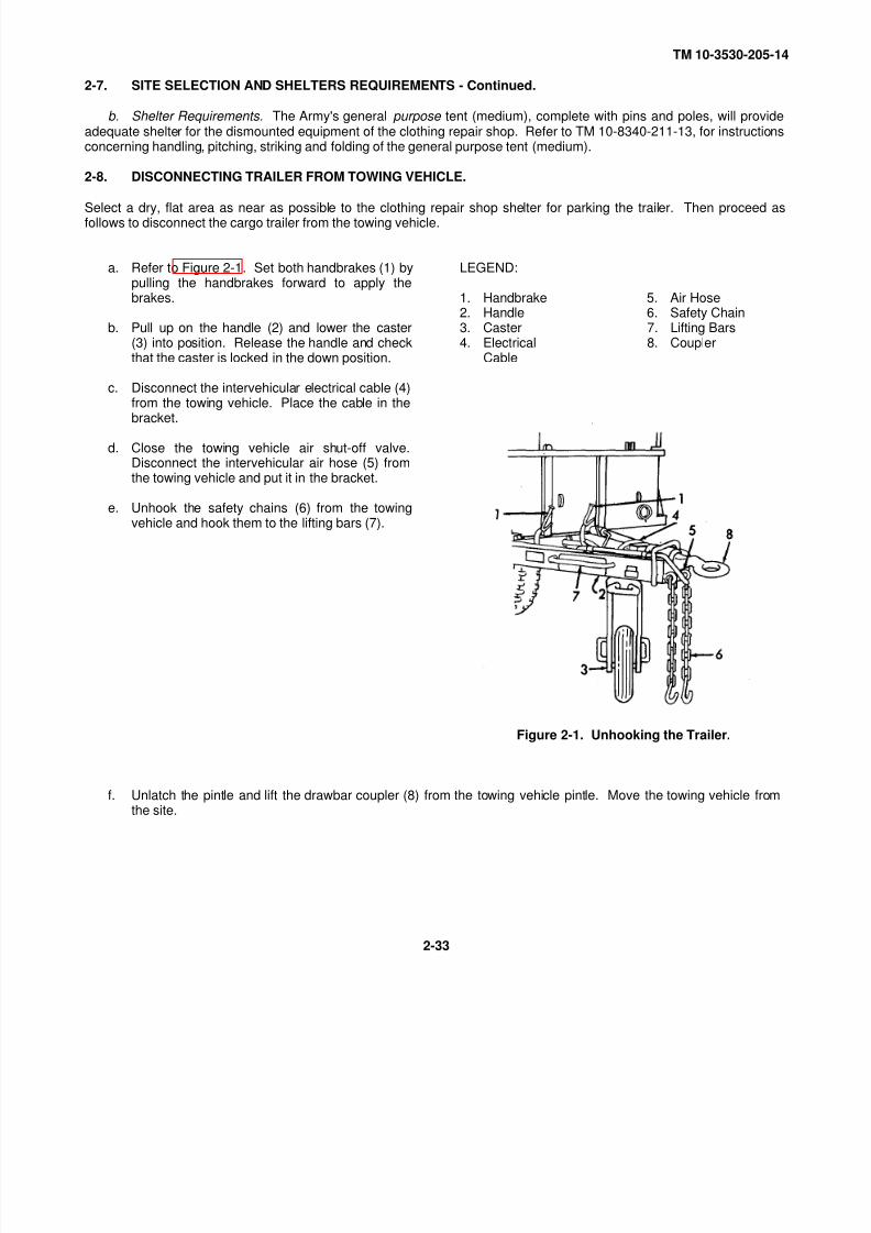
8/7/2019 TM 10-3530-205-10 CLOTHING REPAIR SHOP
http://slidepdf.com/reader/full/tm-10-3530-205-10-clothing-repair-shop 71/455
TM 10-3530-205-14
2-7. SITE SELECTION AND SHELTERS REQUIREMENTS - Continued.
b. Shelter Requirements. The Army's general purpose tent (medium), complete with pins and poles, will provideadequate shelter for the dismounted equipment of the clothing repair shop. Refer to TM 10-8340-211-13, for instructionsconcerning handling, pitching, striking and folding of the general purpose tent (medium).
2-8. DISCONNECTING TRAILER FROM TOWING VEHICLE.
Select a dry, flat area as near as possible to the clothing repair shop shelter for parking the trailer. Then proceed asfollows to disconnect the cargo trailer from the towing vehicle.
a. Refer t o Figure 2-1 . Set both handbrakes (1) bypulling the handbrakes forward to apply thebrakes.
b. Pull up on the handle (2) and lower the caster(3) into position. Release the handle and checkthat the caster is locked in the down position.
c. Disconnect the intervehicular electrical cable (4)from the towing vehicle. Place the cable in thebracket.
d. Close the towing vehicle air shut-off valve.Disconnect the intervehicular air hose (5) fromthe towing vehicle and put it in the bracket.
e. Unhook the safety chains (6) from the towingvehicle and hook them to the lifting bars (7).
LEGEND:
1. Handbrake 5. Air Hose2. Handle 6. Safety Chain3. Caster 7. Lifting Bars4. Electrical 8. Coupler
Cable
Figure 2-1. Unhooking the Trailer.
f. Unlatch the pintle and lift the drawbar coupler (8) from the towing vehicle pintle. Move the towing vehicle fromthe site.
2-33
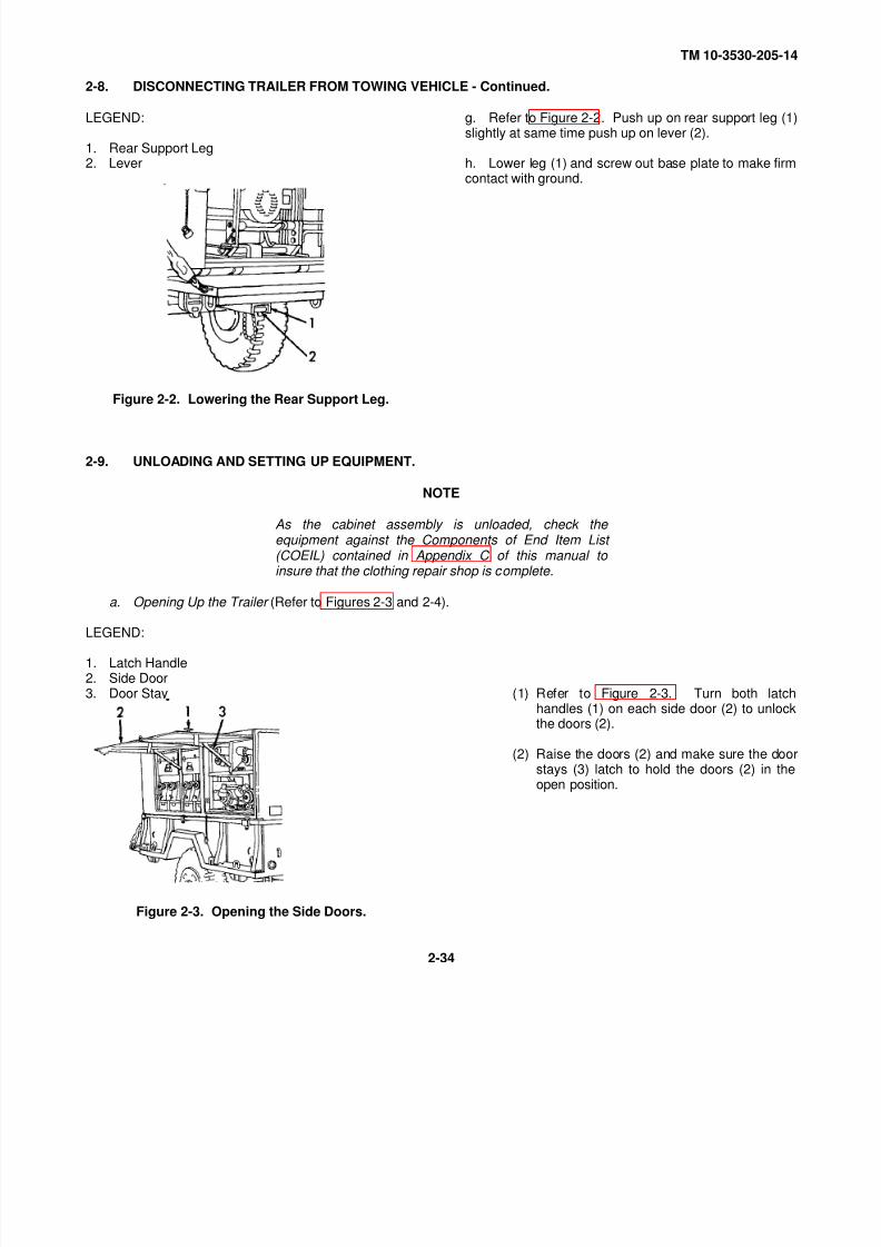
8/7/2019 TM 10-3530-205-10 CLOTHING REPAIR SHOP
http://slidepdf.com/reader/full/tm-10-3530-205-10-clothing-repair-shop 72/455
TM 10-3530-205-14
2-8. DISCONNECTING TRAILER FROM TOWING VEHICLE - Continued.
LEGEND:
1. Rear Support Leg2. Lever
Figure 2-2. Lowering the Rear Support Leg.
g. Refer t o Figure 2-2 . Push up on rear support leg (1)slightly at same time push up on lever (2).
h. Lower leg (1) and screw out base plate to make firmcontact with ground.
2-9. UNLOADING AND SETTING UP EQUIPMENT.
NOTE
As the cabinet assembly is unloaded, check the equipment against the Components of End Item List (COEIL) contained in Appendix C of this manual to insure that the clothing repair shop is complete.
a. Opening Up the Trailer (Refer to Figures 2-3 and 2-4).
LEGEND:
1. Latch Handle2. Side Door3. Door Stay
Figure 2-3. Opening the Side Doors.
(1) Refer to Figure 2-3. Turn both latchhandles (1) on each side door (2) to unlockthe doors (2).
(2) Raise the doors (2) and make sure the doorstays (3) latch to hold the doors (2) in theopen position.
2-34
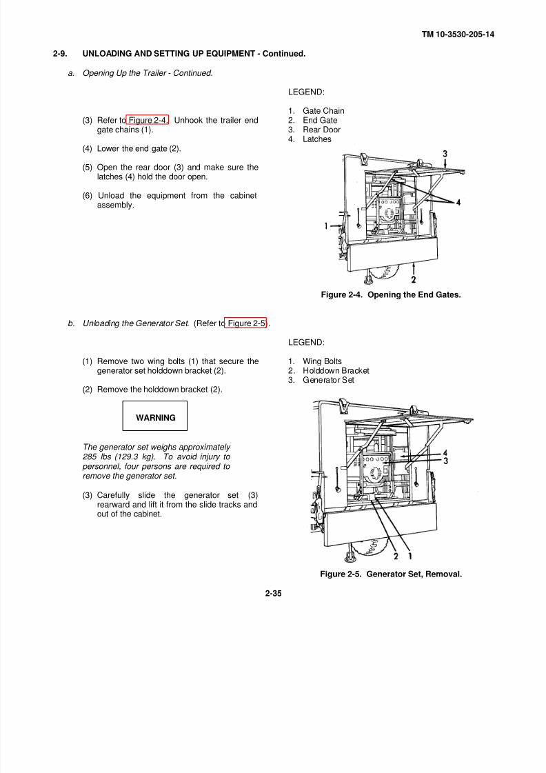
8/7/2019 TM 10-3530-205-10 CLOTHING REPAIR SHOP
http://slidepdf.com/reader/full/tm-10-3530-205-10-clothing-repair-shop 73/455
TM 10-3530-205-14
2-9. UNLOADING AND SETTING UP EQUIPMENT - Continued.
a. Opening Up the Trailer - Continued.
(3) Refer to Figure 2-4. Unhook the trailer endgate chains (1).
(4) Lower the end gate (2).
(5) Open the rear door (3) and make sure thelatches (4) hold the door open.
(6) Unload the equipment from the cabinetassembly.
LEGEND:
1. Gate Chain
2. End Gate3. Rear Door4. Latches
Figure 2-4. Opening the End Gates.
b. Unloading the Generator Set. (Refer to Figure 2-5) .
(1) Remove two wing bolts (1) that secure the
generator set holddown bracket (2).(2) Remove the holddown bracket (2).
WARNING
The generator set weighs approximately 285 lbs (129.3 kg). To avoid injury to personnel, four persons are required to remove the generator set.
(3) Carefully slide the generator set (3)rearward and lift it from the slide tracks andout of the cabinet.
LEGEND:
1. Wing Bolts
2. Holddown Bracket3. Generator Set
Figure 2-5. Generator Set, Removal.
2-35
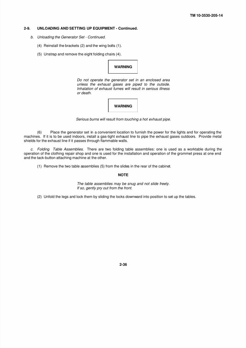
8/7/2019 TM 10-3530-205-10 CLOTHING REPAIR SHOP
http://slidepdf.com/reader/full/tm-10-3530-205-10-clothing-repair-shop 74/455
TM 10-3530-205-14
2-9. UNLOADING AND SETTING UP EQUIPMENT - Continued.
b. Unloading the Generator Set - Continued.
(4) Reinstall the brackets (2) and the wing bolts (1).
(5) Unstrap and remove the eight folding chairs (4).
WARNING
Do not operate the generator set in an enclosed area unless the exhaust gases are piped to the outside.Inhalation of exhaust fumes will result in serious illness or death.
WARNING
Serious burns will result from touching a hot exhaust pipe.
(6) Place the generator set in a convenient location to furnish the power for the lights and for operating themachines. If it is to be used indoors, install a gas-tight exhaust line to pipe the exhaust gases outdoors. Provide metalshields for the exhaust line if it passes through flammable walls.
c. Folding Table Assemblies. There are two folding table assemblies: one is used as a worktable during theoperation of the clothing repair shop and one is used for the installation and operation of the grommet press at one endand the tack-button attaching machine at the other.
(1) Remove the two table assemblies (5) from the slides in the rear of the cabinet.
NOTE
The table assemblies may be snug and not slide freely.If so, gently pry out from the front.
(2) Unfold the legs and lock them by sliding the locks downward into position to set up the tables.
2-36
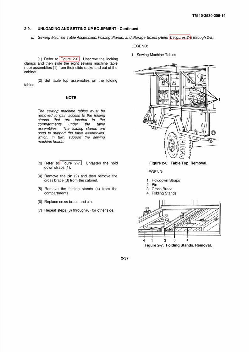
8/7/2019 TM 10-3530-205-10 CLOTHING REPAIR SHOP
http://slidepdf.com/reader/full/tm-10-3530-205-10-clothing-repair-shop 75/455
TM 10-3530-205-14
2-9. UNLOADING AND SETTING UP EQUIPMENT - Continued.
d. Sewing Machine Table Assemblies, Folding Stands, and Storage Boxes (Refer t o Figures 2- 6 through 2-8).
(1) Refer to Figure 2-6. Unscrew the lockingclamps and then slide the eight sewing machine table(top) assemblies (1) from their slide racks and out of thecabinet.
(2) Set table top assemblies on the foldingtables.
NOTE
The sewing machine tables must be removed to gain access to the folding stands that are located in the compartments under the table assemblies. The folding stands are used to support the table assemblies,which, in turn, support the sewing machine heads.
(3) Refer to Figure 2-7. Unfasten the holddown straps (1).
(4) Remove the pin (2) and then remove thecross brace (3) from the cabinet.
(5) Remove the folding stands (4) from thecompartments.
(6) Replace cross brace and pin.
(7) Repeat steps (3) through (6) for other side.
LEGEND:
1. Sewing Machine Tables
Figure 2-6. Table Top, Removal.
LEGEND:
1. Holddown Straps2. Pin3. Cross Brace4. Folding Stands
Figure 2-7. Folding Stands, Removal.
2-37
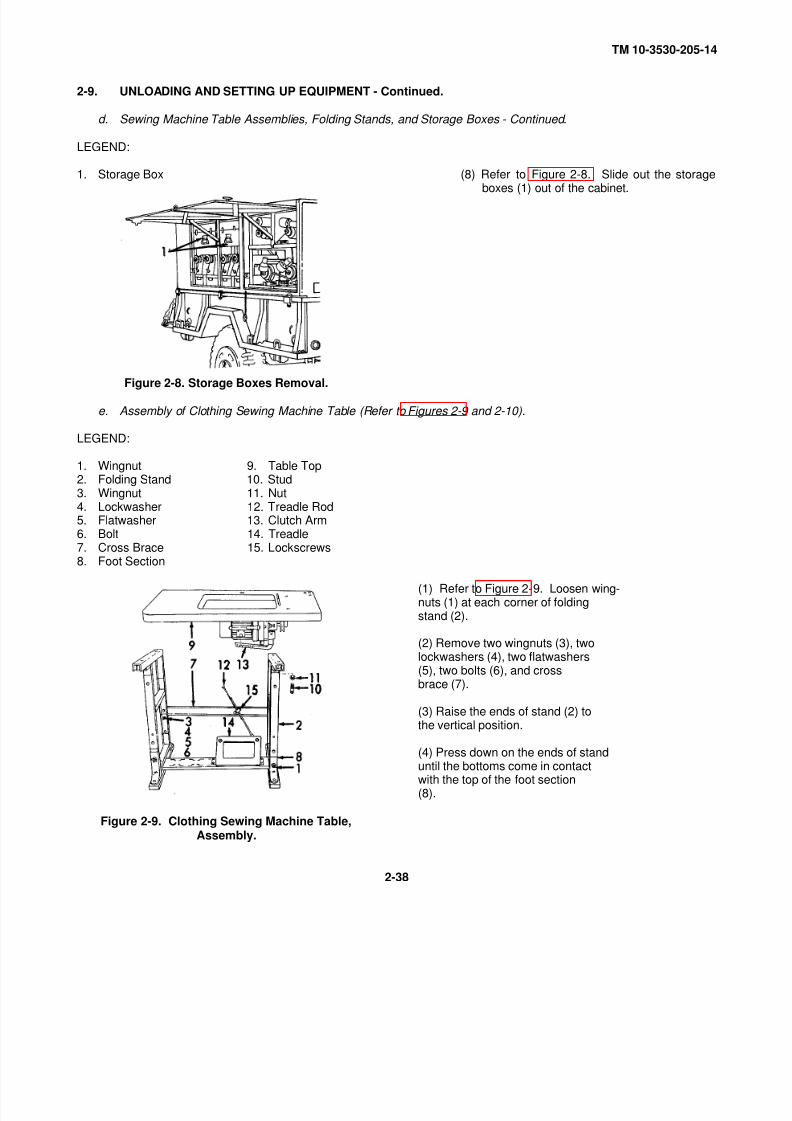
8/7/2019 TM 10-3530-205-10 CLOTHING REPAIR SHOP
http://slidepdf.com/reader/full/tm-10-3530-205-10-clothing-repair-shop 76/455
TM 10-3530-205-14
2-9. UNLOADING AND SETTING UP EQUIPMENT - Continued.
d. Sewing Machine Table Assemblies, Folding Stands, and Storage Boxes - Continued.
LEGEND:
1. Storage Box
Figure 2-8. Storage Boxes Removal.
(8) Refer to Figure 2-8. Slide out the storageboxes (1) out of the cabinet.
e. Assembly of Clothing Sewing Machine Table (Refer to Figures 2-9 and 2-10).
LEGEND:
1. Wingnut 9. Table Top2. Folding Stand 10. Stud3. Wingnut 11. Nut4. Lockwasher 12. Treadle Rod5. Flatwasher 13. Clutch Arm6. Bolt 14. Treadle7. Cross Brace 15. Lockscrews8. Foot Section
Figure 2-9. Clothing Sewing Machine Table,Assembly.
(1) Refer t o Figure 2- 9. Loosen wing-nuts (1) at each corner of foldingstand (2).
(2) Remove two wingnuts (3), twolockwashers (4), two flatwashers(5), two bolts (6), and crossbrace (7).
(3) Raise the ends of stand (2) tothe vertical position.
(4) Press down on the ends of standuntil the bottoms come in contactwith the top of the foot section(8).
2-38
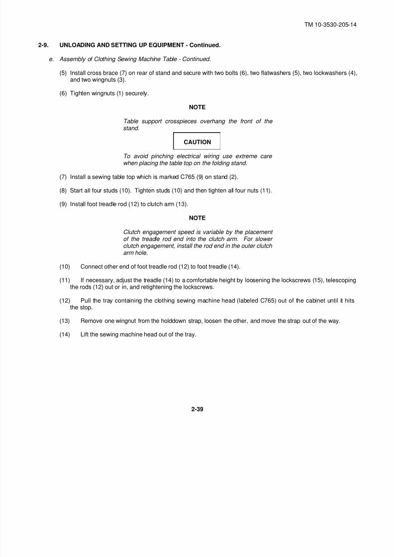
8/7/2019 TM 10-3530-205-10 CLOTHING REPAIR SHOP
http://slidepdf.com/reader/full/tm-10-3530-205-10-clothing-repair-shop 77/455
TM 10-3530-205-14
2-9. UNLOADING AND SETTING UP EQUIPMENT - Continued.
e. Assembly of Clothing Sewing Machine Table - Continued.
(5) Install cross brace (7) on rear of stand and secure with two bolts (6), two flatwashers (5), two lockwashers (4),and two wingnuts (3).
(6) Tighten wingnuts (1) securely.
NOTE
Table support crosspieces overhang the front of the stand.
CAUTION
To avoid pinching electrical wiring use extreme care when placing the table top on the folding stand.
(7) Install a sewing table top which is marked C765 (9) on stand (2).(8) Start all four studs (10). Tighten studs (10) and then tighten all four nuts (11).
(9) Install foot treadle rod (12) to clutch arm (13).
NOTE
Clutch engagement speed is variable by the placement of the treadle rod end into the clutch arm. For slower clutch engagement, install the rod end in the outer clutch arm hole.
(10) Connect other end of foot treadle rod (12) to foot treadle (14).(11) If necessary, adjust the treadle (14) to a comfortable height by loosening the lockscrews (15), telescoping
the rods (12) out or in, and retightening the lockscrews.
(12) Pull the tray containing the clothing sewing machine head (labeled C765) out of the cabinet until it hitsthe stop.
(13) Remove one wingnut from the holddown strap, loosen the other, and move the strap out of the way.
(14) Lift the sewing machine head out of the tray.
2-39
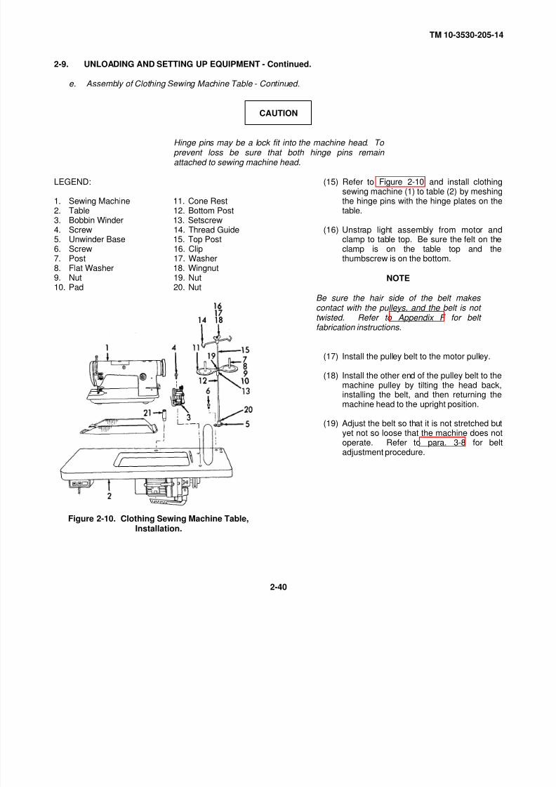
8/7/2019 TM 10-3530-205-10 CLOTHING REPAIR SHOP
http://slidepdf.com/reader/full/tm-10-3530-205-10-clothing-repair-shop 78/455
TM 10-3530-205-14
2-9. UNLOADING AND SETTING UP EQUIPMENT - Continued.
e. Assembly of Clothing Sewing Machine Table - Continued.
CAUTION
Hinge pins may be a lock fit into the machine head. To prevent loss be sure that both hinge pins remain attached to sewing machine head.
LEGEND:
1. Sewing Machine 11. Cone Rest2. Table 12. Bottom Post3. Bobbin Winder 13. Setscrew4. Screw 14. Thread Guide5. Unwinder Base 15. Top Post6. Screw 16. Clip7. Post 17. Washer8. Flat Washer 18. Wingnut9. Nut 19. Nut10. Pad 20. Nut
Figure 2-10. Clothing Sewing Machine Table,Installation.
(15) Refer to Figure 2-10 and install clothingsewing machine (1) to table (2) by meshingthe hinge pins with the hinge plates on thetable.
(16) Unstrap light assembly from motor andclamp to table top. Be sure the felt on theclamp is on the table top and thethumbscrew is on the bottom.
NOTE
Be sure the hair side of the belt makes contact with the pulleys, and the belt is not twisted. Refer to Appendix F for belt fabrication instructions.
(17) Install the pulley belt to the motor pulley.
(18) Install the other end of the pulley belt to themachine pulley by tilting the head back,installing the belt, and then returning themachine head to the upright position.
(19) Adjust the belt so that it is not stretched butyet not so loose that the machine does notoperate. Refer to para. 3-8 for beltadjustment procedure.
2-40
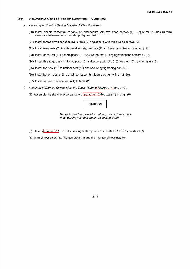
8/7/2019 TM 10-3530-205-10 CLOTHING REPAIR SHOP
http://slidepdf.com/reader/full/tm-10-3530-205-10-clothing-repair-shop 79/455
TM 10-3530-205-14
2-9. UNLOADING AND SETTING UP EQUIPMENT - Continued.
e. Assembly of Clothing Sewing Machine Table - Continued.
(20) Install bobbin winder (3) to table (2) and secure with two wood screws (4). Adjust for 1/8 inch (3 mm)clearance between bobbin winder pulley and belt.
(21) Install thread unwinder base (5) to table (2) and secure with three wood screws (6).(22) Install two posts (7), two flat washers (8), two nuts (9), and two pads (10) to cone rest (11).
(23) Install cone rest (11) bottom post (12). Secure the rest (11) by tightening the setscrew (13).
(24) Install thread guides (14) to top post (15) and secure with clip (16), washer (17), and wingnut (18).
(25) Install top post (15) to bottom post (12) and secure by tightening nut (19).
(26) Install bottom post (12) to unwinder base (5). Secure by tightening nut (20).
(27) Install sewing machine rest (21) to table (2).
f. Assembly of Darning Sewing Machine Table (Refer to Figures 2-11 and 2-12).
(1) Assemble the stand in accordance with paragraph 2-9 e, steps (1) through (6).
CAUTION
To avoid pinching electrical wiring, use extreme care when placing the table top on the folding stand.
(2) Refer to Figure 2-11 . Install a sewing table top which is labeled 678HD (1) on stand (2).
(3) Start all four studs (3). Tighten studs (3) and then tighten all four nuts (4).
2-41
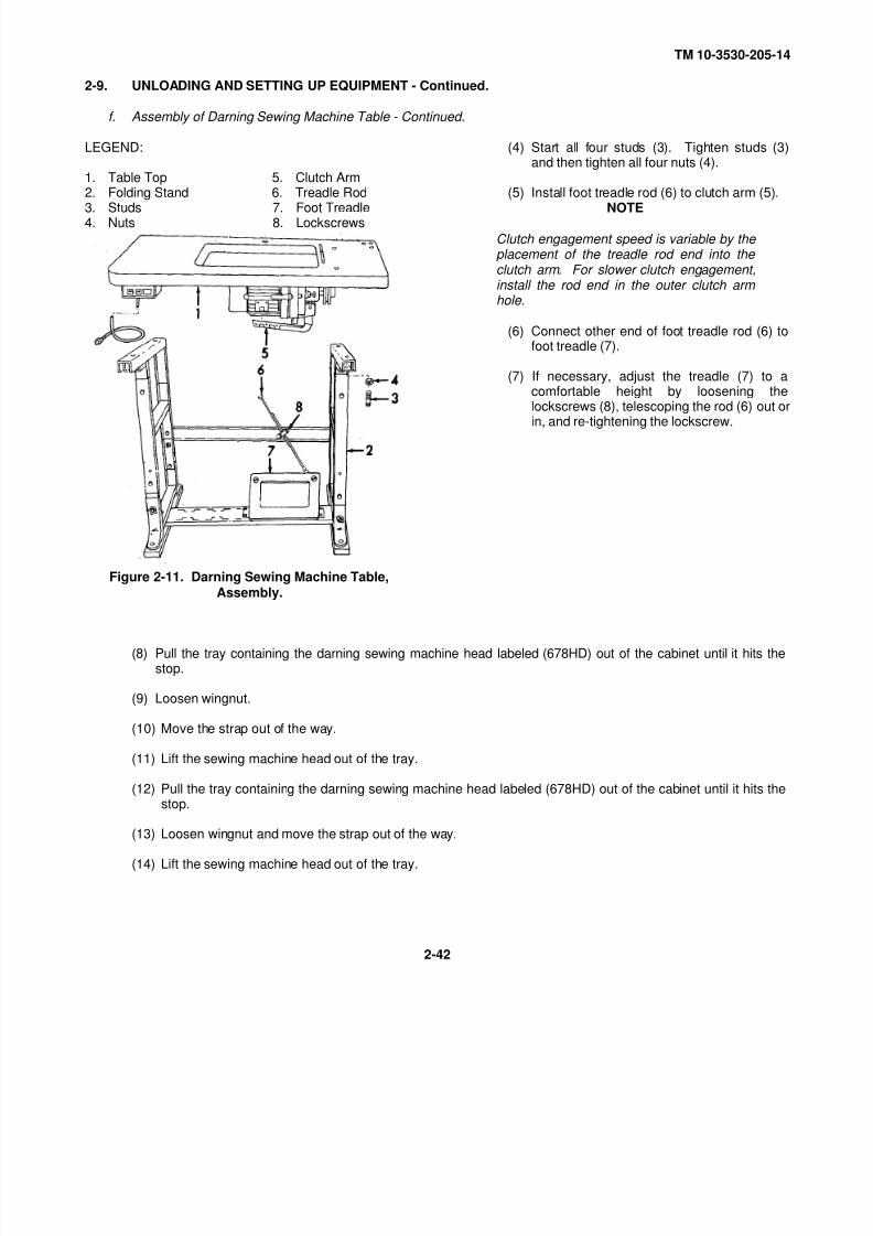
8/7/2019 TM 10-3530-205-10 CLOTHING REPAIR SHOP
http://slidepdf.com/reader/full/tm-10-3530-205-10-clothing-repair-shop 80/455
TM 10-3530-205-14
2-9. UNLOADING AND SETTING UP EQUIPMENT - Continued.
f. Assembly of Darning Sewing Machine Table - Continued.
LEGEND:
1. Table Top 5. Clutch Arm
2. Folding Stand 6. Treadle Rod3. Studs 7. Foot Treadle4. Nuts 8. Lockscrews
Figure 2-11. Darning Sewing Machine Table,
Assembly.
(4) Start all four studs (3). Tighten studs (3)and then tighten all four nuts (4).
(5) Install foot treadle rod (6) to clutch arm (5).NOTE
Clutch engagement speed is variable by the placement of the treadle rod end into the clutch arm. For slower clutch engagement,install the rod end in the outer clutch arm hole.
(6) Connect other end of foot treadle rod (6) tofoot treadle (7).
(7) If necessary, adjust the treadle (7) to acomfortable height by loosening thelockscrews (8), telescoping the rod (6) out orin, and re-tightening the lockscrew.
(8) Pull the tray containing the darning sewing machine head labeled (678HD) out of the cabinet until it hits thestop.
(9) Loosen wingnut.
(10) Move the strap out of the way.
(11) Lift the sewing machine head out of the tray.
(12) Pull the tray containing the darning sewing machine head labeled (678HD) out of the cabinet until it hits thestop.
(13) Loosen wingnut and move the strap out of the way.
(14) Lift the sewing machine head out of the tray.
2-42
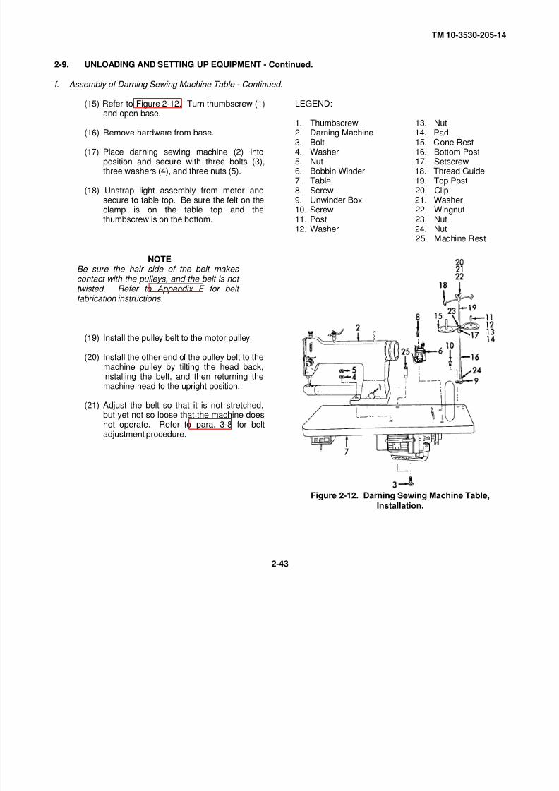
8/7/2019 TM 10-3530-205-10 CLOTHING REPAIR SHOP
http://slidepdf.com/reader/full/tm-10-3530-205-10-clothing-repair-shop 81/455
TM 10-3530-205-14
2-9. UNLOADING AND SETTING UP EQUIPMENT - Continued.
f. Assembly of Darning Sewing Machine Table - Continued.
(15) Refer to Figure 2-12. Turn thumbscrew (1)and open base.
(16) Remove hardware from base.
(17) Place darning sewing machine (2) intoposition and secure with three bolts (3),three washers (4), and three nuts (5).
(18) Unstrap light assembly from motor andsecure to table top. Be sure the felt on theclamp is on the table top and thethumbscrew is on the bottom.
NOTEBe sure the hair side of the belt makes contact with the pulleys, and the belt is not twisted. Refer to Appendix F for belt fabrication instructions.
(19) Install the pulley belt to the motor pulley.
(20) Install the other end of the pulley belt to themachine pulley by tilting the head back,installing the belt, and then returning themachine head to the upright position.
(21) Adjust the belt so that it is not stretched,but yet not so loose that the machine doesnot operate. Refer to para. 3-8 for beltadjustment procedure.
LEGEND:
1. Thumbscrew 13. Nut2. Darning Machine 14. Pad3. Bolt 15. Cone Rest4. Washer 16. Bottom Post5. Nut 17. Setscrew6. Bobbin Winder 18. Thread Guide7. Table 19. Top Post8. Screw 20. Clip9. Unwinder Box 21. Washer10. Screw 22. Wingnut11. Post 23. Nut12. Washer 24. Nut
25. Machine Rest
Figure 2-12. Darning Sewing Machine Table,Installation.
2-43
8/7/2019 TM 10-3530-205-10 CLOTHING REPAIR SHOP
http://slidepdf.com/reader/full/tm-10-3530-205-10-clothing-repair-shop 82/455
TM 10-3530-205-14
2-9. UNLOADING AND SETTING UP EQUIPMENT - Continued.
f. Assembly of Darning Sewing Machine Table - Continued.
(22) Install bobbin winder (6) to table (7) and secure with two wood screws(8). Adjust for 1/8 inch (3 mm)clearance between bobbin winder pulley and belt.
(23) Install thread unwinder base (9) to table (7) and secure with three wood screws (10).
(24) Install two posts (11), two flat washers (12), two nuts (13), and two pads (14) to cone rest (15).
(25) Install cone rest (15) bottom post (16). Secure the rest (15) by tightening the setscrew (17).
(26) Install thread guides (18) to top post (19) and secure with clip (20), washer (21), and wingnut (22).
(27) Install top post (19) to bottom post (16) and secure by tightening nut (23).
(28) Install bottom post (16) to unwinder base (9). Secure by tightening nut (24).
(29) Install sewing machine rest (25) to table (7).
g. Assembly of Button Sewing Machine Table (Refer to Figures 2-13 and 2-14).
(1) Assemble the stand in accordance with paragraph 2-9 e, steps (1) through (6).
CAUTION
To avoid pinching electrical wiring use extreme care when placing the table top on the folding stand.
(2) Refer to Figure 2-13 . Install a sewing table top which is labeled 600-10 (1) on stand (2).
(3) Start all four studs (3). Tighten studs (3) and then tighten all four nuts (4).
(4) Pull the tray containing the button sewing machine head labeled (600-10) out of the cabinet until it hits thestop.
2-44
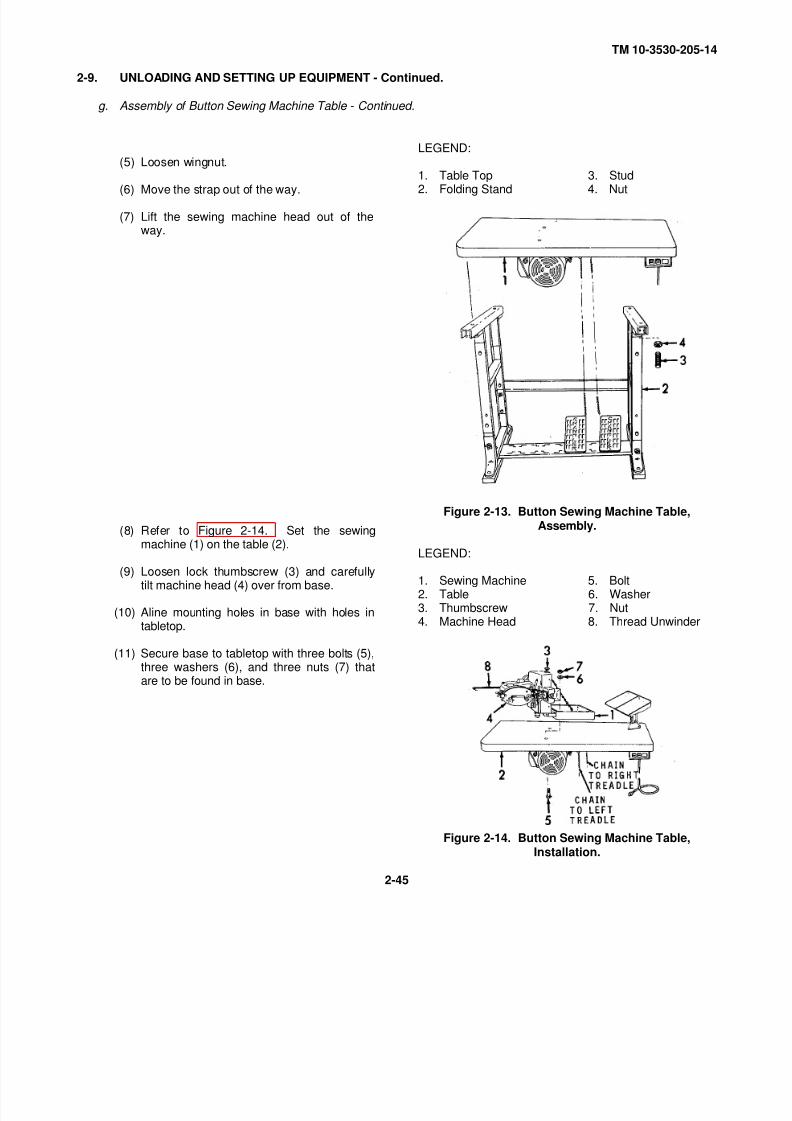
8/7/2019 TM 10-3530-205-10 CLOTHING REPAIR SHOP
http://slidepdf.com/reader/full/tm-10-3530-205-10-clothing-repair-shop 83/455
TM 10-3530-205-14
2-9. UNLOADING AND SETTING UP EQUIPMENT - Continued.
g. Assembly of Button Sewing Machine Table - Continued.
(5) Loosen wingnut.
(6) Move the strap out of the way.
(7) Lift the sewing machine head out of theway.
(8) Refer to Figure 2-14. Set the sewingmachine (1) on the table (2).
(9) Loosen lock thumbscrew (3) and carefullytilt machine head (4) over from base.
(10) Aline mounting holes in base with holes intabletop.
(11) Secure base to tabletop with three bolts (5),three washers (6), and three nuts (7) thatare to be found in base.
LEGEND:
1. Table Top 3. Stud2. Folding Stand 4. Nut
Figure 2-13. Button Sewing Machine Table,Assembly.
LEGEND:
1. Sewing Machine 5. Bolt2. Table 6. Washer3. Thumbscrew 7. Nut4. Machine Head 8. Thread Unwinder
Figure 2-14. Button Sewing Machine Table,Installation.
2-45
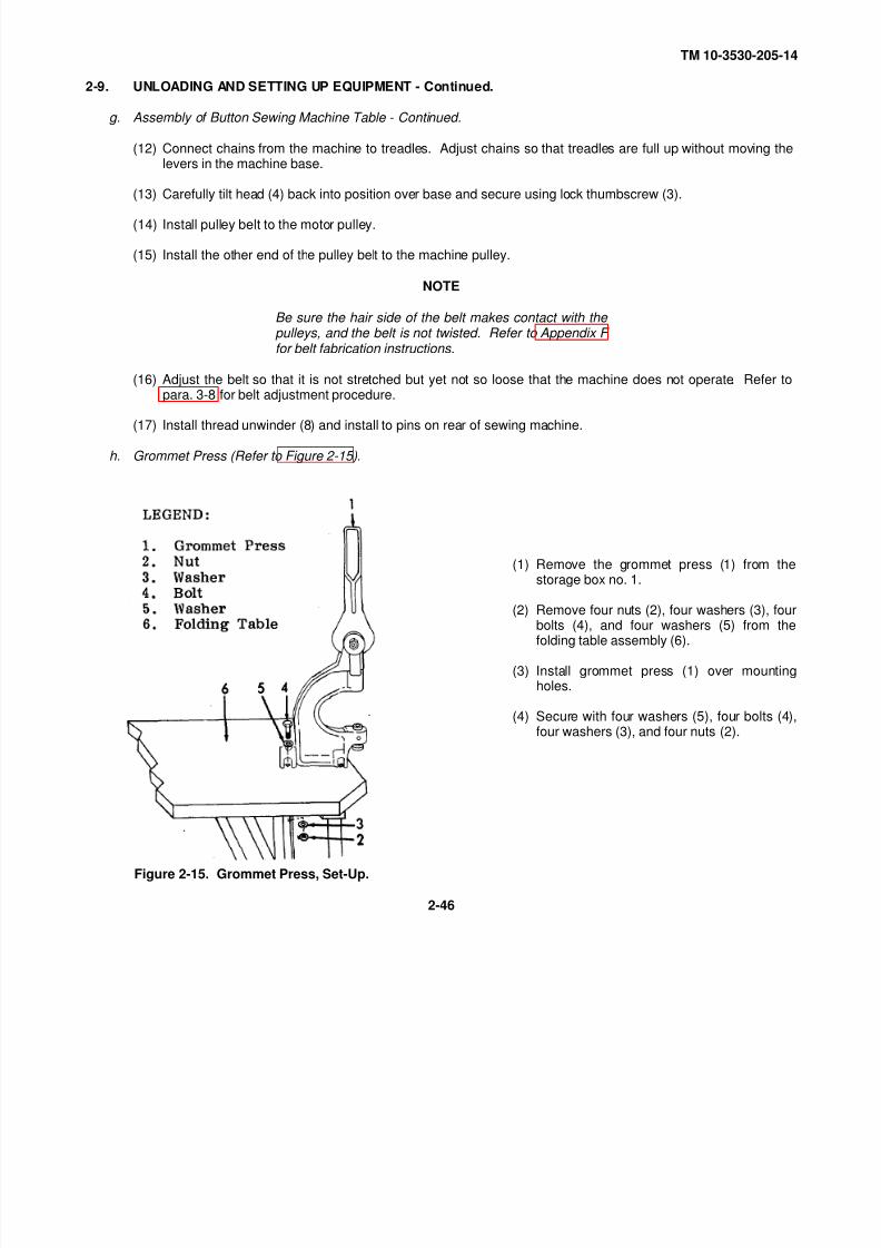
8/7/2019 TM 10-3530-205-10 CLOTHING REPAIR SHOP
http://slidepdf.com/reader/full/tm-10-3530-205-10-clothing-repair-shop 84/455
TM 10-3530-205-14
2-9. UNLOADING AND SETTING UP EQUIPMENT - Continued.
g. Assembly of Button Sewing Machine Table - Continued.
(12) Connect chains from the machine to treadles. Adjust chains so that treadles are full up without moving thelevers in the machine base.
(13) Carefully tilt head (4) back into position over base and secure using lock thumbscrew (3).(14) Install pulley belt to the motor pulley.
(15) Install the other end of the pulley belt to the machine pulley.
NOTE
Be sure the hair side of the belt makes contact with the pulleys, and the belt is not twisted. Refer to Appendix F for belt fabrication instructions.
(16) Adjust the belt so that it is not stretched but yet not so loose that the machine does not operate. Refer topara. 3-8 for belt adjustment procedure.
(17) Install thread unwinder (8) and install to pins on rear of sewing machine.
h. Grommet Press (Refer to Figure 2-15) .
Figure 2-15. Grommet Press, Set-Up.
(1) Remove the grommet press (1) from thestorage box no. 1.
(2) Remove four nuts (2), four washers (3), fourbolts (4), and four washers (5) from thefolding table assembly (6).
(3) Install grommet press (1) over mountingholes.
(4) Secure with four washers (5), four bolts (4),four washers (3), and four nuts (2).
2-46
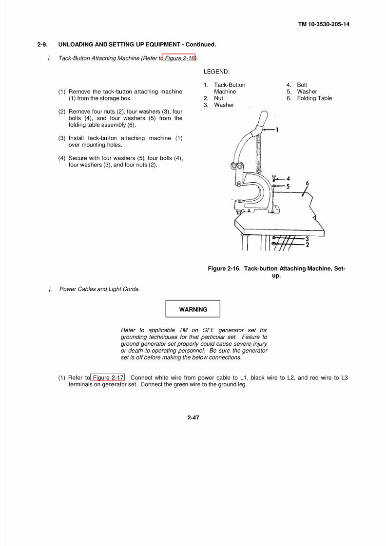
8/7/2019 TM 10-3530-205-10 CLOTHING REPAIR SHOP
http://slidepdf.com/reader/full/tm-10-3530-205-10-clothing-repair-shop 85/455
TM 10-3530-205-14
2-9. UNLOADING AND SETTING UP EQUIPMENT - Continued.
i. Tack-Button Attaching Machine (Refer to Figure 2-16) .
(1) Remove the tack-button attaching machine(1) from the storage box.
(2) Remove four nuts (2), four washers (3), fourbolts (4), and four washers (5) from thefolding table assembly (6).
(3) Install tack-button attaching machine (1)over mounting holes.
(4) Secure with four washers (5), four bolts (4),four washers (3), and four nuts (2).
LEGEND:
1. Tack-Button 4. BoltMachine 5. Washer2. Nut 6. Folding Table3. Washer
Figure 2-16 . Tack-button Attaching Machine, Set-up.
j. Power Cables and Light Cords.
WARNING
Refer to applicable TM on GFE generator set for grounding techniques for that particular set. Failure to ground generator set properly could cause severe injury
or death to operating personnel. Be sure the generator set is off before making the below connections.
(1) Refer to Figure 2-17. Connect white wire from power cable to L1, black wire to L2, and red wire to L3terminals on generator set. Connect the green wire to the ground leg.
2-47
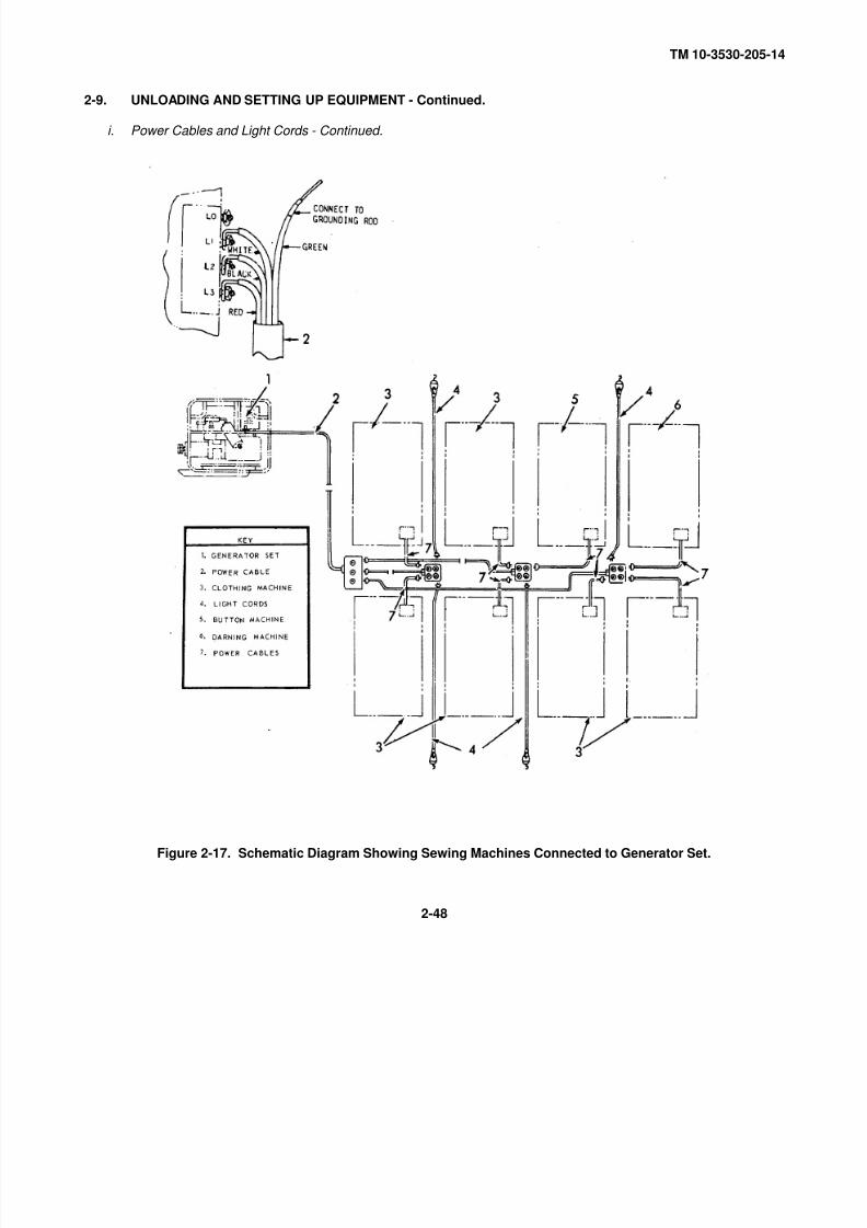
8/7/2019 TM 10-3530-205-10 CLOTHING REPAIR SHOP
http://slidepdf.com/reader/full/tm-10-3530-205-10-clothing-repair-shop 86/455
TM 10-3530-205-14
2-9. UNLOADING AND SETTING UP EQUIPMENT - Continued.
i. Power Cables and Light Cords - Continued.
Figure 2-17. Schematic Diagram Showing Sewing Machines Connected to Generator Set.
2-48
8/7/2019 TM 10-3530-205-10 CLOTHING REPAIR SHOP
http://slidepdf.com/reader/full/tm-10-3530-205-10-clothing-repair-shop 87/455
TM 10-3530-205-14
2-9. UNLOADING AND SETTING UP EQUIPMENT - Continued.
i. Power Cables and Light Cords - Continued.
NOTE
The receptacles on the three 2-duplex outlet power cables are marked with the letters M and L for proper load distribution. The sewing machines must be plugged in the receptacles marked with the letter M and the light cords must be plugged in the receptacles marked with the letter L.
(2) Connect the three 2-duplex outlet power cables to the 3-receptacle outlet power cable (connected to thegenerator set).
(3) Connect the four light cords to the 2-duplex outlet power cable receptacles marked with the letter L.
(4) Connect the sewing machine power cords to the 2-duplex outlet power cable receptacles marked with theletter M.
k. Fire Extinguisher. Open the fire extinguisher bracket and remove the fire extinguisher from the cabinet. Place itin a convenient location near the work area.
2-10. OPERATING INSTRUCTIONS.
The following paragraphs are presented to provide guidance and assist you in getting the best performance from theequipment. You, the operator, must know how to perform every operation of which the equipment is capable. Beforeoperating the equipment, read through the operating procedures that apply to the equipment you are to operate. This willgive you an overall "feel" for what is to be done.
2-11. OPERATION OF AUXILIARY EQUIPMENT.
Refer to TM 5-6115-271-14 to operate the generator set.
2-49
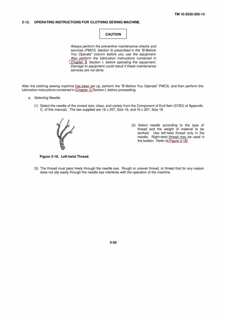
8/7/2019 TM 10-3530-205-10 CLOTHING REPAIR SHOP
http://slidepdf.com/reader/full/tm-10-3530-205-10-clothing-repair-shop 88/455
TM 10-3530-205-14
2-12. OPERATING INSTRUCTIONS FOR CLOTHING SEWING MACHINE.
CAUTION
Always perform the preventive maintenance checks and
services (PMCS, Section II) prescribed in the "B-Before You Operate" column before you use the equipment.Also perform the lubrication instructions contained in Chapter 3, Section I, before operating the equipment.Damage to equipment could result if these maintenance services are not done.
After the clothing sewing machine has been set up, perform the "B-Before You Operate" PMCS, and then perform thelubrication instructions contained in Chapter 3, Section I, before proceeding.
a. Selecting Needle.
(1) Select the needle of the correct size, class, and variety from the Component of End Item (COEI) of AppendixC, of this manual). The two supplied are 16 x 257, Size 16, and 16 x 257, Size 18.
Figure 2-18. Left-twist Thread.
(2) Select needle according to the type ofthread and the weight of material to beworked. Use left-twist thread only in theneedle. Right-twist thread may be used inthe bobbin. Refer to Figure 2-18.
(3) The thread must pass freely through the needle eye. Rough or uneven thread, or thread that for any reasondoes not slip easily through the needle eye interferes with the operation of the machine.
2-50
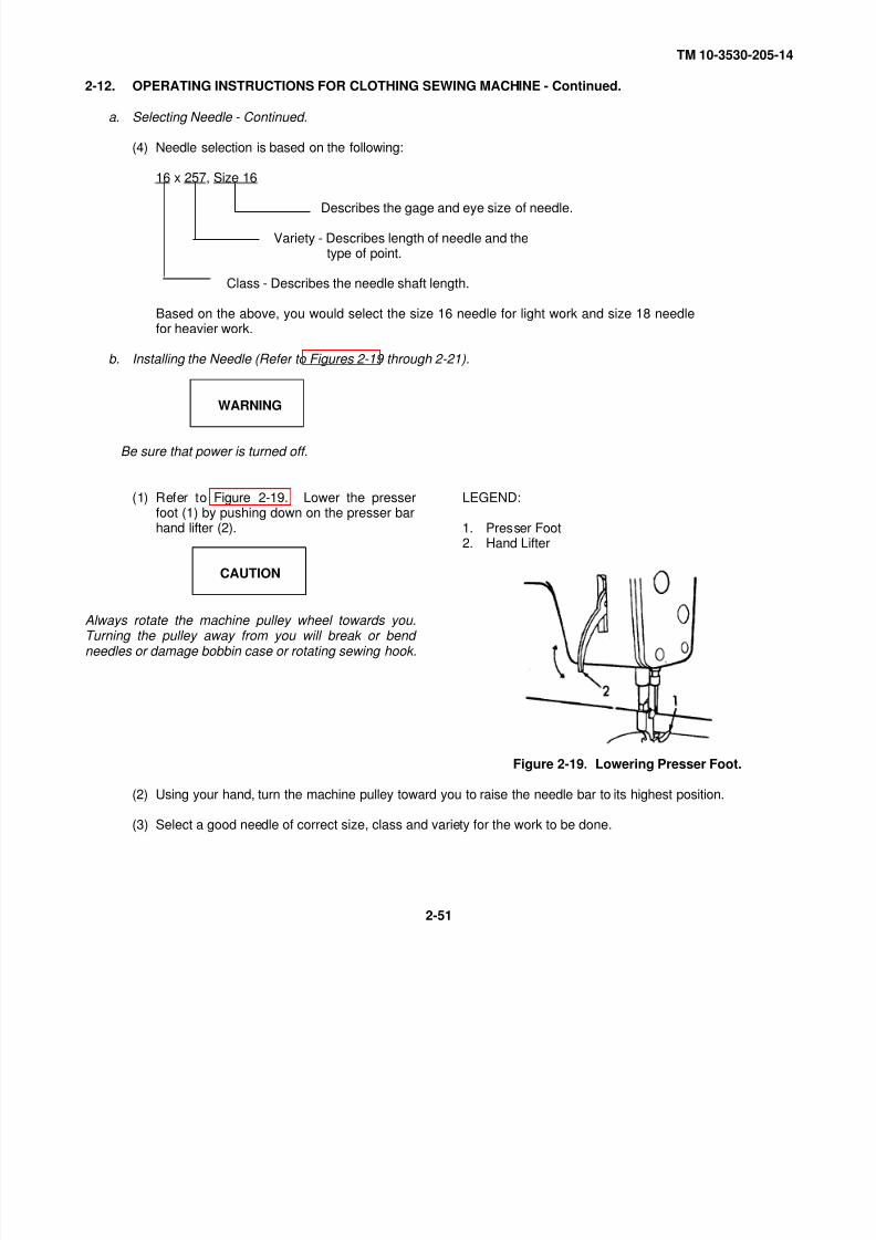
8/7/2019 TM 10-3530-205-10 CLOTHING REPAIR SHOP
http://slidepdf.com/reader/full/tm-10-3530-205-10-clothing-repair-shop 89/455
TM 10-3530-205-14
2-12. OPERATING INSTRUCTIONS FOR CLOTHING SEWING MACHINE - Continued.
a. Selecting Needle - Continued.
(4) Needle selection is based on the following:
16 x 257, Size 16
Describes the gage and eye size of needle.
Variety - Describes length of needle and thetype of point.
Class - Describes the needle shaft length.
Based on the above, you would select the size 16 needle for light work and size 18 needlefor heavier work.
b. Installing the Needle (Refer to Figures 2-19 through 2-21).
WARNING
Be sure that power is turned off.
(1) Refer to Figure 2-19. Lower the presserfoot (1) by pushing down on the presser barhand lifter (2).
CAUTION
Always rotate the machine pulley wheel towards you.Turning the pulley away from you will break or bend needles or damage bobbin case or rotating sewing hook.
LEGEND:
1. Presser Foot2. Hand Lifter
Figure 2-19. Lowering Presser Foot.
(2) Using your hand, turn the machine pulley toward you to raise the needle bar to its highest position.(3) Select a good needle of correct size, class and variety for the work to be done.
2-51
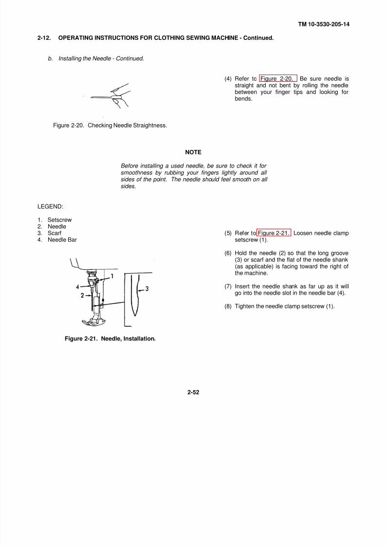
8/7/2019 TM 10-3530-205-10 CLOTHING REPAIR SHOP
http://slidepdf.com/reader/full/tm-10-3530-205-10-clothing-repair-shop 90/455
TM 10-3530-205-14
2-12. OPERATING INSTRUCTIONS FOR CLOTHING SEWING MACHINE - Continued.
b. Installing the Needle - Continued.
Figure 2-20. Checking Needle Straightness.
(4) Refer to Figure 2-20. Be sure needle is
straight and not bent by rolling the needlebetween your finger tips and looking forbends.
NOTE
Before installing a used needle, be sure to check it for smoothness by rubbing your fingers lightly around all sides of the point. The needle should feel smooth on all sides.
LEGEND:
1. Setscrew2. Needle3. Scarf4. Needle Bar
Figure 2-21. Needle, Installation.
(5) Refer to Figure 2-21. Loosen needle clampsetscrew (1).
(6) Hold the needle (2) so that the long groove(3) or scarf and the flat of the needle shank(as applicable) is facing toward the right ofthe machine.
(7) Insert the needle shank as far up as it willgo into the needle slot in the needle bar (4).
(8) Tighten the needle clamp setscrew (1).
2-52
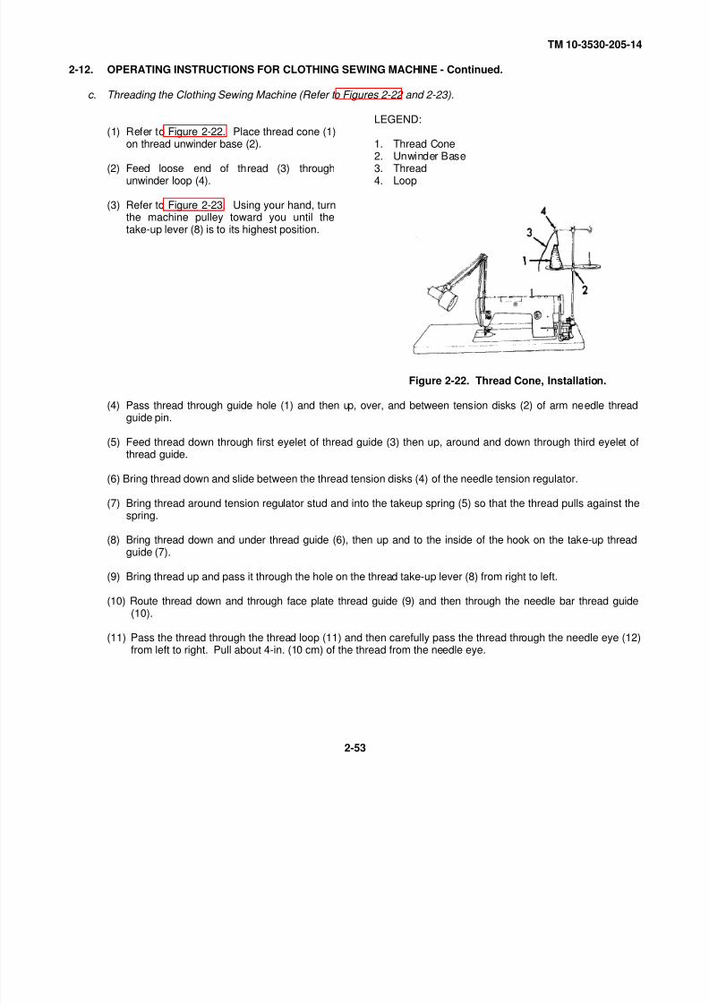
8/7/2019 TM 10-3530-205-10 CLOTHING REPAIR SHOP
http://slidepdf.com/reader/full/tm-10-3530-205-10-clothing-repair-shop 91/455
TM 10-3530-205-14
2-12. OPERATING INSTRUCTIONS FOR CLOTHING SEWING MACHINE - Continued.
c. Threading the Clothing Sewing Machine (Refer t o Figures 2-22 and 2-23).
(1) Refer to Figure 2-22. Place thread cone (1)on thread unwinder base (2).
(2) Feed loose end of thread (3) throughunwinder loop (4).
(3) Refer to Figure 2-23. Using your hand, turnthe machine pulley toward you until thetake-up lever (8) is to its highest position.
LEGEND:
1. Thread Cone
2. Unwinder Base3. Thread4. Loop
Figure 2-22. Thread Cone, Installation.
(4) Pass thread through guide hole (1) and then up, over, and between tension disks (2) of arm needle threadguide pin.
(5) Feed thread down through first eyelet of thread guide (3) then up, around and down through third eyelet ofthread guide.
(6) Bring thread down and slide between the thread tension disks (4) of the needle tension regulator.
(7) Bring thread around tension regulator stud and into the takeup spring (5) so that the thread pulls against thespring.
(8) Bring thread down and under thread guide (6), then up and to the inside of the hook on the take-up threadguide (7).
(9) Bring thread up and pass it through the hole on the thread take-up lever (8) from right to left.
(10) Route thread down and through face plate thread guide (9) and then through the needle bar thread guide(10).
(11) Pass the thread through the thread loop (11) and then carefully pass the thread through the needle eye (12)from left to right. Pull about 4-in. (10 cm) of the thread from the needle eye.
2-53
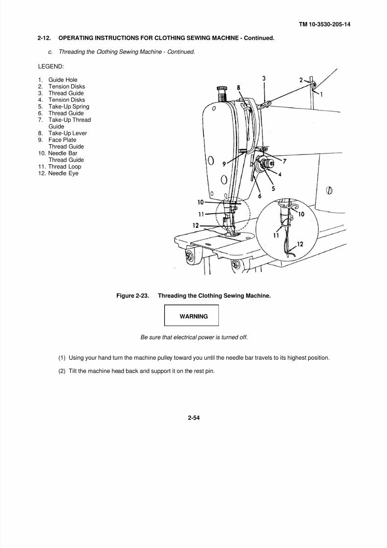
8/7/2019 TM 10-3530-205-10 CLOTHING REPAIR SHOP
http://slidepdf.com/reader/full/tm-10-3530-205-10-clothing-repair-shop 92/455
TM 10-3530-205-14
2-12. OPERATING INSTRUCTIONS FOR CLOTHING SEWING MACHINE - Continued.
c. Threading the Clothing Sewing Machine - Continued.
Figure 2-23. Threading the Clothing Sewing Machine.
WARNING
Be sure that electrical power is turned off.
(1) Using your hand turn the machine pulley toward you until the needle bar travels to its highest position.
(2) Tilt the machine head back and support it on the rest pin.
2-54
LEGEND:
1. Guide Hole
2. Tension Disks3. Thread Guide4. Tension Disks5. Take-Up Spring6. Thread Guide7. Take-Up Thread
Guide8. Take-Up Lever9. Face Plate
Thread Guide10. Needle Bar
Thread Guide11. Thread Loop12. Needle Eye
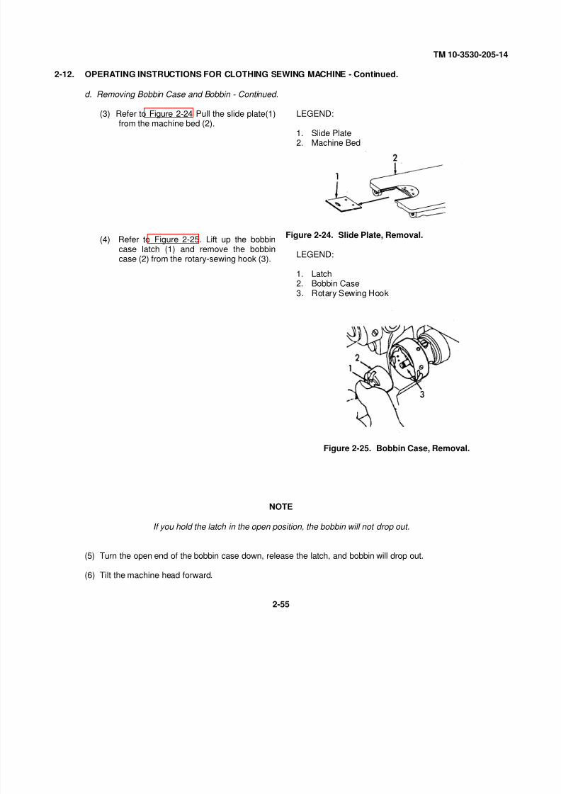
8/7/2019 TM 10-3530-205-10 CLOTHING REPAIR SHOP
http://slidepdf.com/reader/full/tm-10-3530-205-10-clothing-repair-shop 93/455
TM 10-3530-205-14
2-12. OPERATING INSTRUCTIONS FOR CLOTHING SEWING MACHINE - Continued.
d. Removing Bobbin Case and Bobbin - Continued.
(3) Refer to Figure 2-24 Pull the slide plate(1)
from the machine bed (2).
(4) Refer to Figure 2-25 . Lift up the bobbincase latch (1) and remove the bobbincase (2) from the rotary-sewing hook (3).
LEGEND:
1. Slide Plate2. Machine Bed
Figure 2-24. Slide Plate, Removal.
LEGEND:
1. Latch2. Bobbin Case3. Rotary Sewing Hook
Figure 2-25. Bobbin Case, Removal.
NOTE
If you hold the latch in the open position, the bobbin will not drop out.
(5) Turn the open end of the bobbin case down, release the latch, and bobbin will drop out.
(6) Tilt the machine head forward.
2-55
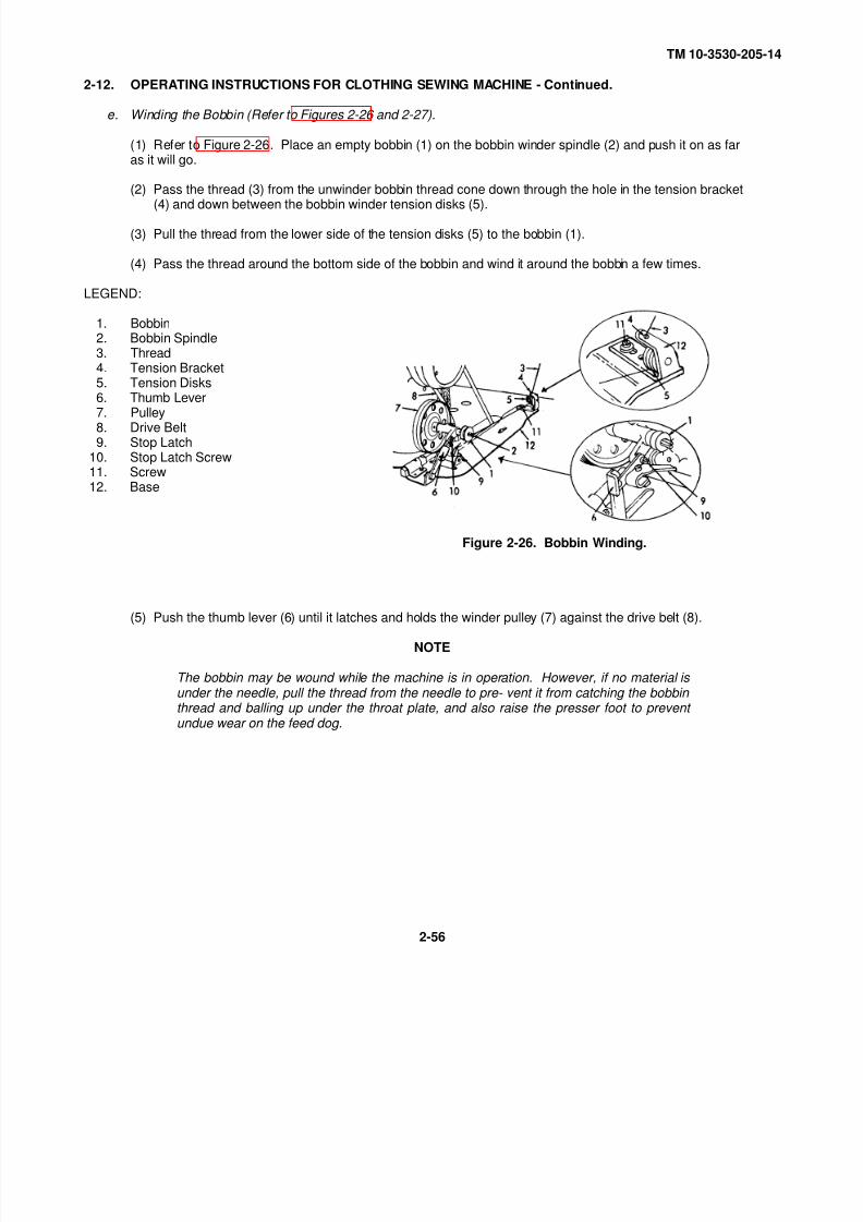
8/7/2019 TM 10-3530-205-10 CLOTHING REPAIR SHOP
http://slidepdf.com/reader/full/tm-10-3530-205-10-clothing-repair-shop 94/455
TM 10-3530-205-14
2-12. OPERATING INSTRUCTIONS FOR CLOTHING SEWING MACHINE - Continued.
e. Winding the Bobbin (Refer to Figures 2-26 and 2-27).
(1) Refer to Figure 2-26 . Place an empty bobbin (1) on the bobbin winder spindle (2) and push it on as faras it will go.
(2) Pass the thread (3) from the unwinder bobbin thread cone down through the hole in the tension bracket(4) and down between the bobbin winder tension disks (5).
(3) Pull the thread from the lower side of the tension disks (5) to the bobbin (1).
(4) Pass the thread around the bottom side of the bobbin and wind it around the bobbin a few times.
LEGEND:
1. Bobbin2. Bobbin Spindle3. Thread4. Tension Bracket5. Tension Disks6. Thumb Lever7. Pulley8. Drive Belt9. Stop Latch
10. Stop Latch Screw11. Screw12. Base
Figure 2-26. Bobbin Winding.
(5) Push the thumb lever (6) until it latches and holds the winder pulley (7) against the drive belt (8).
NOTE
The bobbin may be wound while the machine is in operation. However, if no material is under the needle, pull the thread from the needle to pre- vent it from catching the bobbin thread and balling up under the throat plate, and also raise the presser foot to prevent undue wear on the feed dog.
2-56
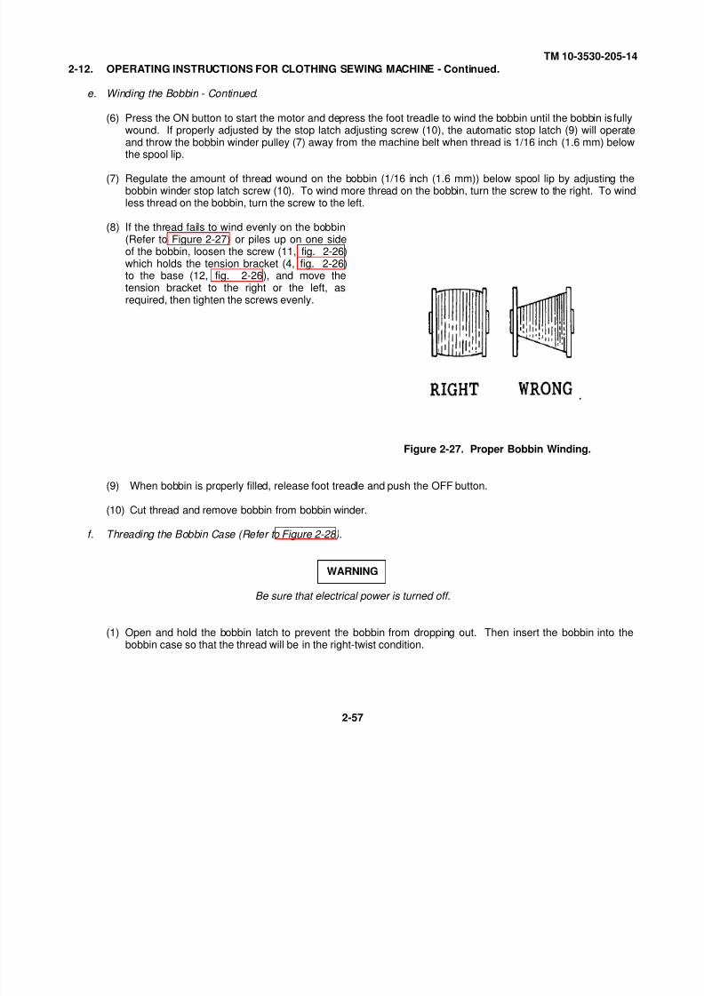
8/7/2019 TM 10-3530-205-10 CLOTHING REPAIR SHOP
http://slidepdf.com/reader/full/tm-10-3530-205-10-clothing-repair-shop 95/455
TM 10-3530-205-142-12. OPERATING INSTRUCTIONS FOR CLOTHING SEWING MACHINE - Continued.
e. Winding the Bobbin - Continued .
(6) Press the ON button to start the motor and depress the foot treadle to wind the bobbin until the bobbin is fullywound. If properly adjusted by the stop latch adjusting screw (10), the automatic stop latch (9) will operateand throw the bobbin winder pulley (7) away from the machine belt when thread is 1/16 inch (1.6 mm) belowthe spool lip.
(7) Regulate the amount of thread wound on the bobbin (1/16 inch (1.6 mm)) below spool lip by adjusting thebobbin winder stop latch screw (10). To wind more thread on the bobbin, turn the screw to the right. To windless thread on the bobbin, turn the screw to the left.
(8) If the thread fails to wind evenly on the bobbin(Refer to Figure 2-27) or piles up on one sideof the bobbin, loosen the screw (11, fig. 2-26)which holds the tension bracket (4, fig. 2-26)to the base (12, fig. 2-26 ), and move thetension bracket to the right or the left, asrequired, then tighten the screws evenly.
Figure 2-27. Proper Bobbin Winding.
(9) When bobbin is properly filled, release foot treadle and push the OFF button.
(10) Cut thread and remove bobbin from bobbin winder.
f. Threading the Bobbin Case (Refer to Figure 2-28) .
WARNING
Be sure that electrical power is turned off.
(1) Open and hold the bobbin latch to prevent the bobbin from dropping out. Then insert the bobbin into thebobbin case so that the thread will be in the right-twist condition.
2-57
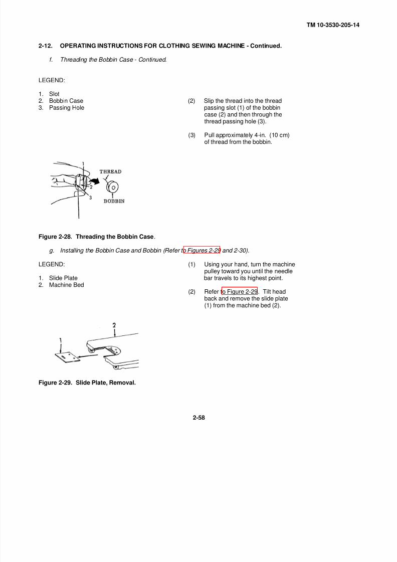
8/7/2019 TM 10-3530-205-10 CLOTHING REPAIR SHOP
http://slidepdf.com/reader/full/tm-10-3530-205-10-clothing-repair-shop 96/455
TM 10-3530-205-14
2-12. OPERATING INSTRUCTIONS FOR CLOTHING SEWING MACHINE - Continued.
f. Threading the Bobbin Case - Continued.
LEGEND:
1. Slot2. Bobbin Case (2) Slip the thread into the thread3. Passing Hole passing slot (1) of the bobbin
case (2) and then through thethread passing hole (3).
(3) Pull approximately 4-in. (10 cm)of thread from the bobbin.
Figure 2-28. Threading the Bobbin Case .
g. Installing the Bobbin Case and Bobbin (Refer to Figures 2-29 and 2-30).
LEGEND: (1) Using your hand, turn the machine
pulley toward you until the needle1. Slide Plate bar travels to its highest point.2. Machine Bed
(2) Refer t o Figure 2-29 . Tilt headback and remove the slide plate(1) from the machine bed (2).
Figure 2-29. Slide Plate, Removal.
2-58
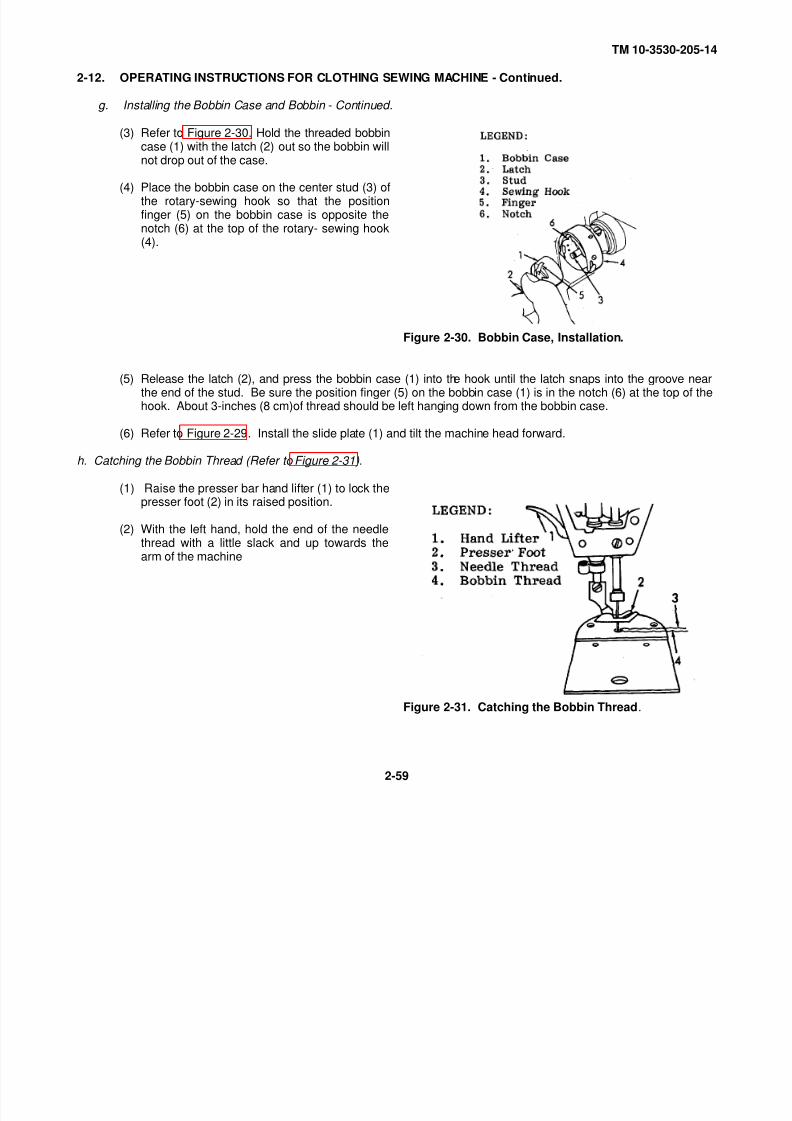
8/7/2019 TM 10-3530-205-10 CLOTHING REPAIR SHOP
http://slidepdf.com/reader/full/tm-10-3530-205-10-clothing-repair-shop 97/455
TM 10-3530-205-14
2-12. OPERATING INSTRUCTIONS FOR CLOTHING SEWING MACHINE - Continued.
g. Installing the Bobbin Case and Bobbin - Continued.
(3) Refer to Figure 2-30. Hold the threaded bobbincase (1) with the latch (2) out so the bobbin willnot drop out of the case.
(4) Place the bobbin case on the center stud (3) ofthe rotary-sewing hook so that the positionfinger (5) on the bobbin case is opposite thenotch (6) at the top of the rotary- sewing hook(4).
Figure 2-30. Bobbin Case, Installation.
(5) Release the latch (2), and press the bobbin case (1) into the hook until the latch snaps into the groove nearthe end of the stud. Be sure the position finger (5) on the bobbin case (1) is in the notch (6) at the top of thehook. About 3-inches (8 cm)of thread should be left hanging down from the bobbin case.
(6) Refer to Figure 2-29 . Install the slide plate (1) and tilt the machine head forward.
h. Catching the Bobbin Thread (Refer to Figure 2-31) .
(1) Raise the presser bar hand lifter (1) to lock thepresser foot (2) in its raised position.
(2) With the left hand, hold the end of the needle
thread with a little slack and up towards thearm of the machine
Figure 2-31. Catching the Bobbin Thread .
2-59
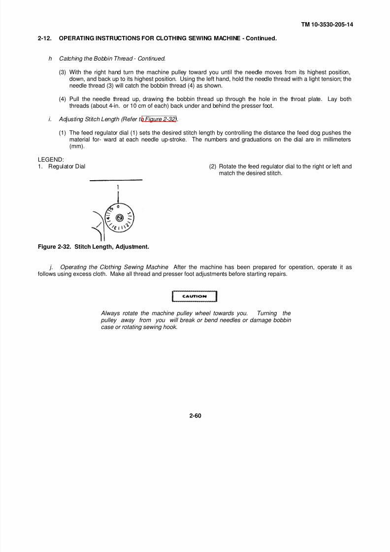
8/7/2019 TM 10-3530-205-10 CLOTHING REPAIR SHOP
http://slidepdf.com/reader/full/tm-10-3530-205-10-clothing-repair-shop 98/455
TM 10-3530-205-14
2-12. OPERATING INSTRUCTIONS FOR CLOTHING SEWING MACHINE - Continued.
h Catching the Bobbin Thread - Continued.
(3) With the right hand turn the machine pulley toward you until the needle moves from its highest position,down, and back up to its highest position. Using the left hand, hold the needle thread with a light tension; theneedle thread (3) will catch the bobbin thread (4) as shown.
(4) Pull the needle thread up, drawing the bobbin thread up through the hole in the throat plate. Lay boththreads (about 4-in. or 10 cm of each) back under and behind the presser foot.
i. Adjusting Stitch Length (Refer to Figure 2-32) .
(1) The feed regulator dial (1) sets the desired stitch length by controlling the distance the feed dog pushes thematerial for- ward at each needle up-stroke. The numbers and graduations on the dial are in millimeters(mm).
LEGEND:1. Regulator Dial
Figure 2-32. Stitch Length, Adjustment.
(2) Rotate the feed regulator dial to the right or left andmatch the desired stitch.
j. Operating the Clothing Sewing Machine . After the machine has been prepared for operation, operate it asfollows using excess cloth. Make all thread and presser foot adjustments before starting repairs.
Always rotate the machine pulley wheel towards you. Turning the pulley away from you will break or bend needles or damage bobbin case or rotating sewing hook.
2-60
8/7/2019 TM 10-3530-205-10 CLOTHING REPAIR SHOP
http://slidepdf.com/reader/full/tm-10-3530-205-10-clothing-repair-shop 99/455
TM 10-3530-205-14
2-12. OPERATING INSTRUCTIONS FOR CLOTHING SEWING MACHINE - Continued.
j. Operating the Clothing Sewing Machine - Continued.NOTE
Before making clothing repairs, make sure of the adjustments by using a piece of scrap cloth.
(1) Inserting Material in Machine.
(a) Lift the presser bar hand lifter to raise the presser foot which now should have about 3-inches of bobbinand needle threads under and behind it.
(b) Place the edge of the material under the presser foot and the needle thread; at the same time hand-turnthe pulley wheel toward you until the needle is in the material at the desired starting point. Place the endof the needle thread toward the rear of the presser foot, and then lower the presser foot on the needlethread and material.
(c) Place the end of the needle thread toward the rear of the presser foot, and then lower the presser foot onthe needle thread and material.
(2) Turning on Power Source. Set motor switch to the ON position.
(3) Sewing Material.
During sewing, hold the material flat and do not push or pull it. Pushing or pulling the cloth may bend the needle or cause it to strike the throat plate resulting in a bent or broken needle.
(a) Hand-turn the pulley wheel toward you and simultaneously hold the needle and bobbin threads until a fewstitches are made. Press the foot treadle slowly to engage the clutch with motor. Let the feed dog carrythe material evenly under the presser foot and needle.
2-61
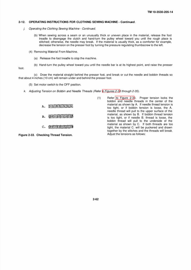
8/7/2019 TM 10-3530-205-10 CLOTHING REPAIR SHOP
http://slidepdf.com/reader/full/tm-10-3530-205-10-clothing-repair-shop 100/455
TM 10-3530-205-14
2-12. OPERATING INSTRUCTIONS FOR CLOTHING SEWING MACHINE - Continued .
j. Operating the Clothing Sewing Machine - Continued.
(b) When sewing across a seam or an unusually thick or uneven place in the material, release the foottreadle to disengage the clutch and hand-turn the pulley wheel toward you until the rough place isstitched; otherwise, the needle may break. If the material is usually thick, as a comforter for example,decrease the tension on the presser foot by turning the pressure regulating thumbscrew to the left.
(4) Removing Material From Machine.
(a) Release the foot treadle to stop the machine.
(b) Hand-turn the pulley wheel toward you until the needle bar is at its highest point, and raise the presserfoot.
(c) Draw the material straight behind the presser foot, and break or cut the needle and bobbin threads sothat about 4 inches (10 cm) will remain under and behind the presser foot.
(5) Set motor switch to the OFF position.
k. Adjusting Tension on Bobbin and Needle Threads (Refer t o Figures 2-33 through 2-35).
Figure 2-33. Checking Thread Tension.
(1) Refer to Figure 2-33 . Proper tension locks thebobbin and needle threads in the center of thematerial as shown by A. If needle thread tension istoo tight, or if bobbin tension is loose, the A.needle thread will pull to the upper surface of thematerial, as shown by B. If bobbin thread tensionis too tight, or if needle B. thread is loose, thebobbin thread will pull to the underside of thematerial as shown by C. If both threads are tootight, the material C. will be puckered and drawn
together by the stitches and the threads will break.Adjust the tensions as follows:
2-62
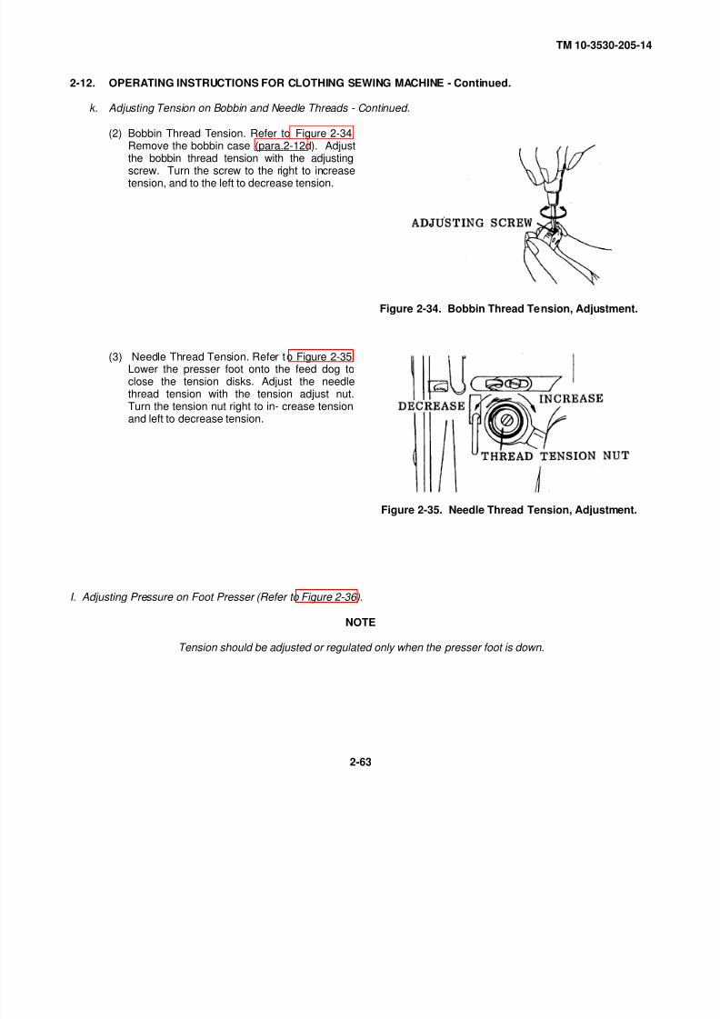
8/7/2019 TM 10-3530-205-10 CLOTHING REPAIR SHOP
http://slidepdf.com/reader/full/tm-10-3530-205-10-clothing-repair-shop 101/455
TM 10-3530-205-14
2-12. OPERATING INSTRUCTIONS FOR CLOTHING SEWING MACHINE - Continued.
k. Adjusting Tension on Bobbin and Needle Threads - Continued.
(2) Bobbin Thread Tension. Refer to Figure 2-34.Remove the bobbin case (para.2-12d ). Adjustthe bobbin thread tension with the adjustingscrew. Turn the screw to the right to increasetension, and to the left to decrease tension.
(3) Needle Thread Tension. Refer t o Figure 2-35.Lower the presser foot onto the feed dog toclose the tension disks. Adjust the needlethread tension with the tension adjust nut.Turn the tension nut right to in- crease tensionand left to decrease tension.
Figure 2-34. Bobbin Thread Tension, Adjustment.
Figure 2-35. Needle Thread Tension, Adjustment.
I. Adjusting Pressure on Foot Presser (Refer to Figure 2-36) .
NOTE
Tension should be adjusted or regulated only when the presser foot is down.
2-63
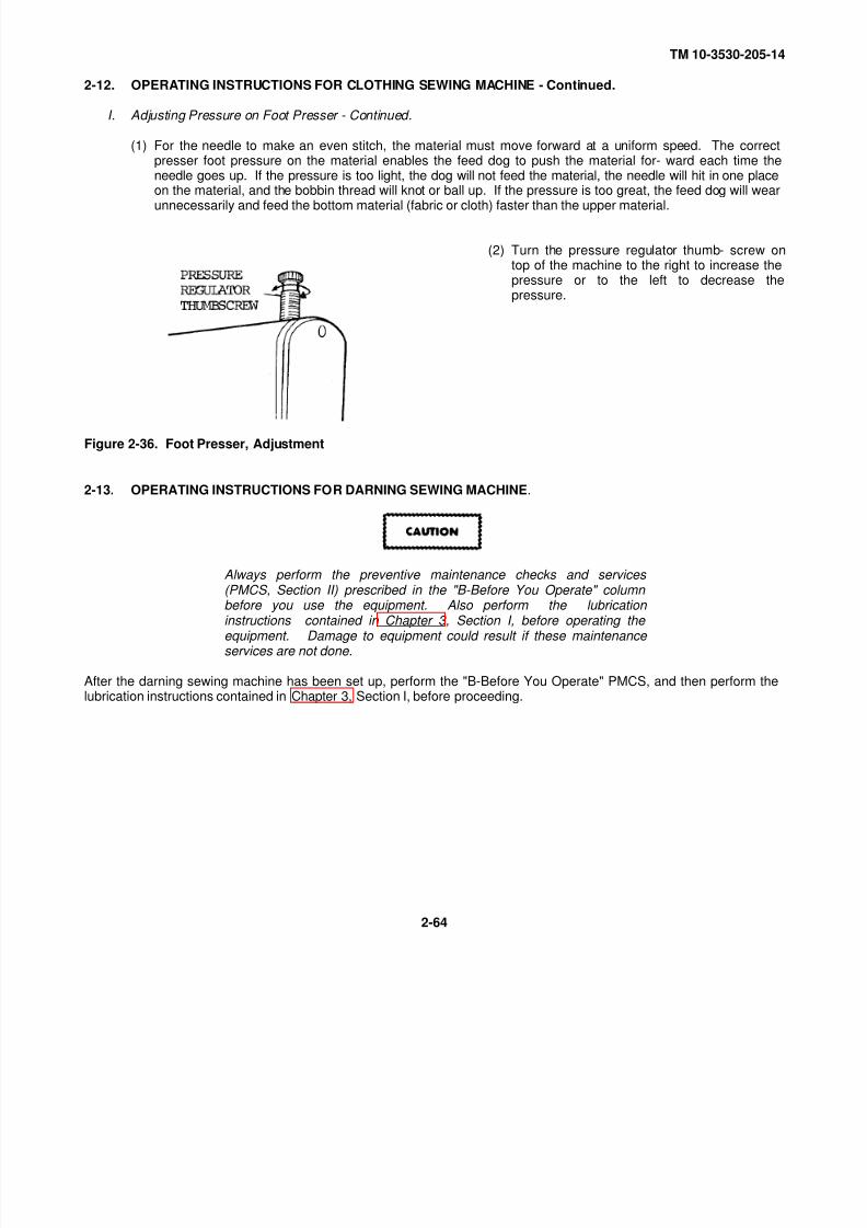
8/7/2019 TM 10-3530-205-10 CLOTHING REPAIR SHOP
http://slidepdf.com/reader/full/tm-10-3530-205-10-clothing-repair-shop 102/455
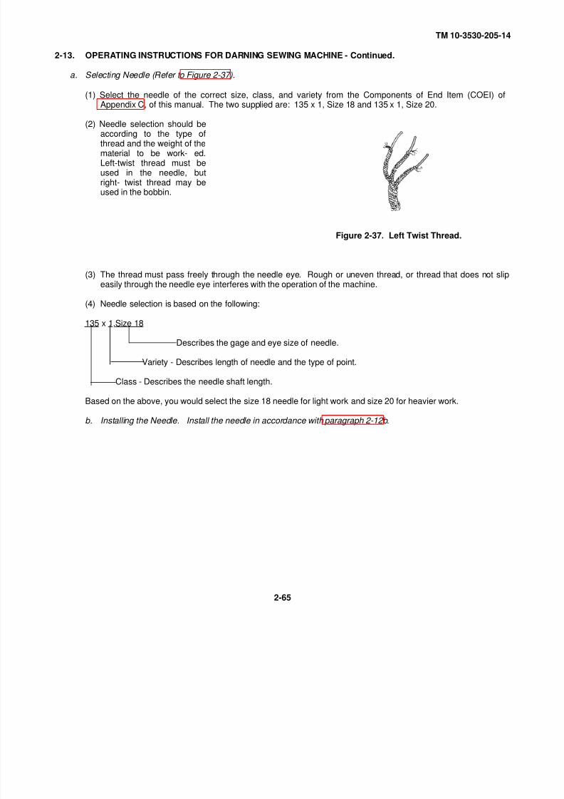
8/7/2019 TM 10-3530-205-10 CLOTHING REPAIR SHOP
http://slidepdf.com/reader/full/tm-10-3530-205-10-clothing-repair-shop 103/455
TM 10-3530-205-14
2-13. OPERATING INSTRUCTIONS FOR DARNING SEWING MACHINE - Continued.
a. Selecting Needle (Refer t o Figure 2-37) .
(1) Select the needle of the correct size, class, and variety from the Components of End Item (COEI) ofAppendix C , of this manual. The two supplied are: 135 x 1, Size 18 and 135 x 1, Size 20.
(2) Needle selection should beaccording to the type ofthread and the weight of thematerial to be work- ed.Left-twist thread must beused in the needle, butright- twist thread may beused in the bobbin.
Figure 2-37. Left Twist Thread.
(3) The thread must pass freely through the needle eye. Rough or uneven thread, or thread that does not slipeasily through the needle eye interferes with the operation of the machine.
(4) Needle selection is based on the following:
135 x 1,Size 18
Describes the gage and eye size of needle.
Variety - Describes length of needle and the type of point.
Class - Describes the needle shaft length.
Based on the above, you would select the size 18 needle for light work and size 20 for heavier work.
b. Installing the Needle. Install the needle in accordance with paragraph 2-12b .
2-65
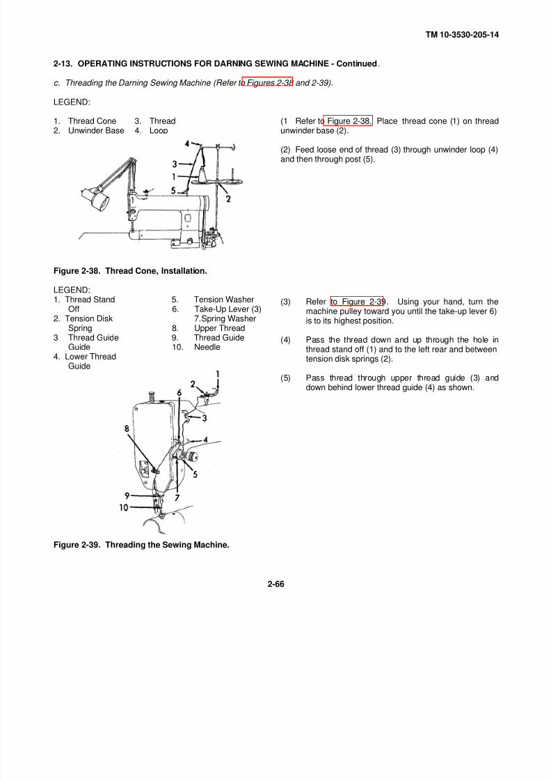
8/7/2019 TM 10-3530-205-10 CLOTHING REPAIR SHOP
http://slidepdf.com/reader/full/tm-10-3530-205-10-clothing-repair-shop 104/455
TM 10-3530-205-14
2-13. OPERATING INSTRUCTIONS FOR DARNING SEWING MACHINE - Continued .
c. Threading the Darning Sewing Machine (Refer to Figures 2-38 and 2-39).
LEGEND:
1. Thread Cone 3. Thread2. Unwinder Base 4. Loop
Figure 2-38. Thread Cone, Installation.
LEGEND:1. Thread Stand 5. Tension Washer
Off 6. Take-Up Lever (3)2. Tension Disk 7.Spring Washer
Spring 8. Upper Thread3 Thread Guide 9. Thread Guide
Guide 10. Needle4. Lower Thread
Guide
Figure 2-39. Threading the Sewing Machine.
(1 Refer to Figure 2-38. Place thread cone (1) on threadunwinder base (2).
(2) Feed loose end of thread (3) through unwinder loop (4)and then through post (5).
(3) Refer to Figure 2-39 . Using your hand, turn themachine pulley toward you until the take-up lever 6)is to its highest position.
(4) Pass the thread down and up through the hole inthread stand off (1) and to the left rear and betweentension disk springs (2).
(5) Pass thread through upper thread guide (3) anddown behind lower thread guide (4) as shown.
2-66
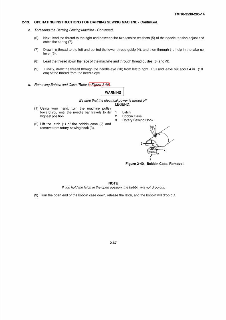
8/7/2019 TM 10-3530-205-10 CLOTHING REPAIR SHOP
http://slidepdf.com/reader/full/tm-10-3530-205-10-clothing-repair-shop 105/455
TM 10-3530-205-14
2-13. OPERATING INSTRUCTIONS FOR DARNING SEWING MACHINE - Continued.
c. Threading the Darning Sewing Machine - Continued.
(6) Next, lead the thread to the right and between the two tension washers (5) of the needle tension adjust andcatch the spring (7).
(7) Draw the thread to the left and behind the lower thread guide (4), and then through the hole in the take-uplever (6).
(8) Lead the thread down the face of the machine and through thread guides (8) and (9).
(9) Finally, draw the thread through the needle eye (10) from left to right. Pull and leave out about 4 in. (10cm) of the thread from the needle eye.
d. Removing Bobbin and Case (Refer t o Figure 2-40) .
WARNING
Be sure that the electrical power is turned off.
(1) Using your hand, turn the machine pulleytoward you until the needle bar travels to itshighest position
(2) Lift the latch (1) of the bobbin case (2) andremove from rotary-sewing hook (3).
LEGEND:
1 Latch2 Bobbin Case3 Rotary Sewing Hook
Figure 2-40. Bobbin Case, Removal.
NOTEIf you hold the latch in the open position, the bobbin will not drop out.
(3) Turn the open end of the bobbin case down, release the latch, and the bobbin will drop out.
2-67
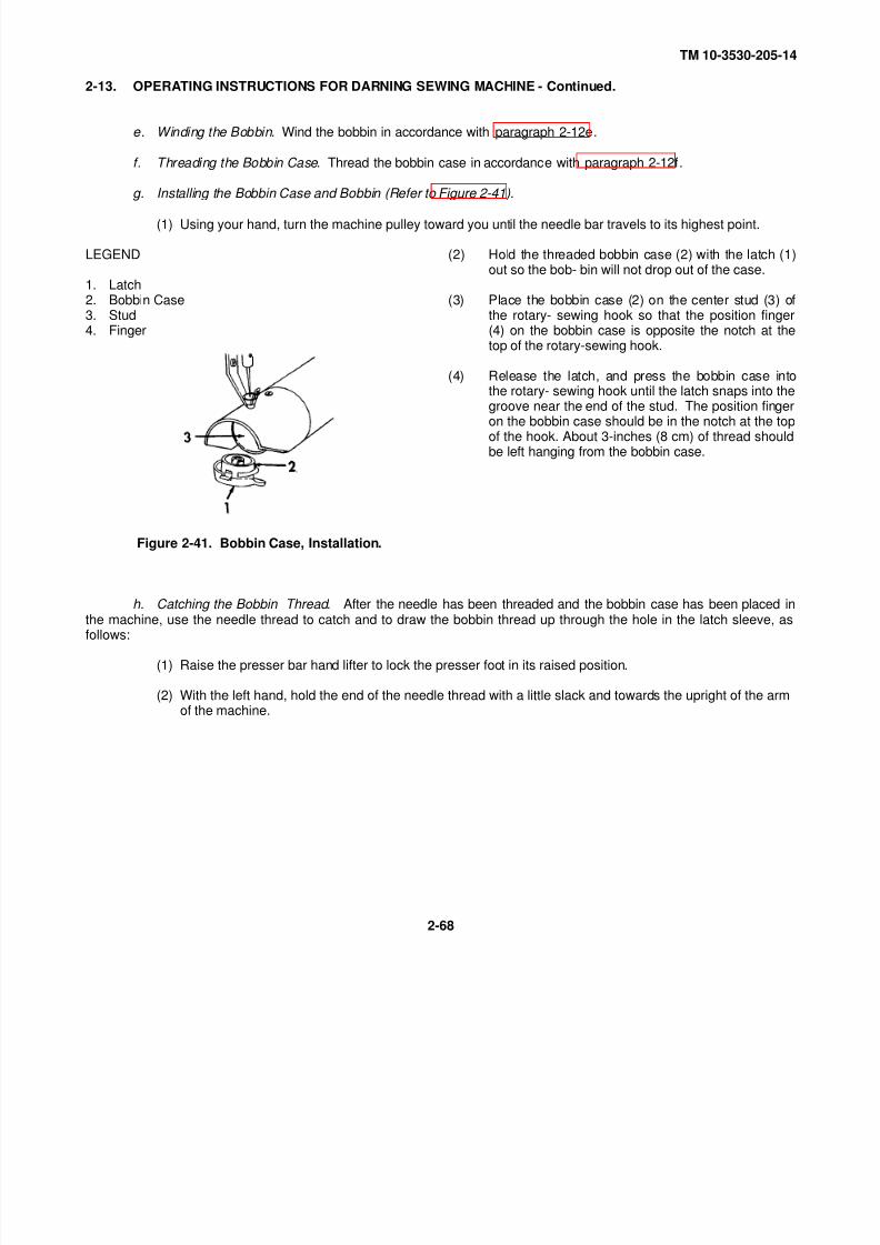
8/7/2019 TM 10-3530-205-10 CLOTHING REPAIR SHOP
http://slidepdf.com/reader/full/tm-10-3530-205-10-clothing-repair-shop 106/455
TM 10-3530-205-14
2-13. OPERATING INSTRUCTIONS FOR DARNING SEWING MACHINE - Continued.
e. Winding the Bobbin. Wind the bobbin in accordance with paragraph 2-12e .
f. Threading the Bobbin Case . Thread the bobbin case in accordance with paragraph 2-12f .
g. Installing the Bobbin Case and Bobbin (Refer to Figure 2-41) .
(1) Using your hand, turn the machine pulley toward you until the needle bar travels to its highest point.
LEGEND
1. Latch2. Bobbin Case3. Stud4. Finger
Figure 2-41. Bobbin Case, Installation.
(2) Hold the threaded bobbin case (2) with the latch (1)out so the bob- bin will not drop out of the case.
(3) Place the bobbin case (2) on the center stud (3) ofthe rotary- sewing hook so that the position finger(4) on the bobbin case is opposite the notch at thetop of the rotary-sewing hook.
(4) Release the latch, and press the bobbin case intothe rotary- sewing hook until the latch snaps into thegroove near the end of the stud. The position fingeron the bobbin case should be in the notch at the topof the hook. About 3-inches (8 cm) of thread shouldbe left hanging from the bobbin case.
h. Catching the Bobbin Thread . After the needle has been threaded and the bobbin case has been placed inthe machine, use the needle thread to catch and to draw the bobbin thread up through the hole in the latch sleeve, asfollows:
(1) Raise the presser bar hand lifter to lock the presser foot in its raised position.
(2) With the left hand, hold the end of the needle thread with a little slack and towards the upright of the armof the machine.
2-68
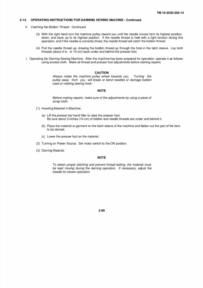
8/7/2019 TM 10-3530-205-10 CLOTHING REPAIR SHOP
http://slidepdf.com/reader/full/tm-10-3530-205-10-clothing-repair-shop 107/455
TM 10-3530-205-14
2-13. OPERATING INSTRUCTIONS FOR DARNING SEWING MACHINE - Continued.
h. Catching the Bobbin Thread - Continued.
(3) With the right hand turn the machine pulley toward you until the needle moves form its highest position,down, and back up to its highest position. If the needle thread is held with a light tension during thisoperation, and if the needle is correctly timed, the needle thread will catch the bobbin thread.
(4) Pull the needle thread up, drawing the bobbin thread up through the hole in the latch sleeve. Lay boththreads (about 4-in. or 10 cm) back under and behind the presser foot.
i. Operating the Darning Sewing Machine. After the machine has been prepared for operation, operate it as followsusing excess cloth. Make all thread and presser foot adjustments before starting repairs.
CAUTIONAlways rotate the machine pulley wheel towards you. Turning the pulley away from you will break or bend needles or damage bobbin case or rotating sewing hook.
NOTE
Before making repairs, make sure of the adjustments by using a piece of scrap cloth.
(1) Inserting Material in Machine.
(a) Lift the presser bar hand lifter to raise the presser foot.Be sure about 3-inches (10 cm) of bobbin and needle threads are under and behind it.
(b) Place the material or garment on the latch sleeve of the machine and flatten out the part of the itemto be darned.
(c) Lower the presser foot on the material.
(2) Turning on Power Source. Set motor switch to the ON position.
(3) Darning Material.
NOTE
To obtain proper stitching and prevent thread balling, the material must be kept moving during the darning operation. If necessary, adjust the treadle for slower operation.
2-69
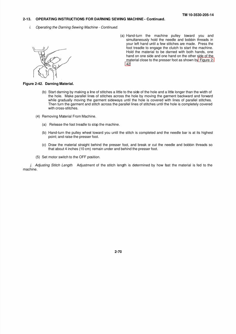
8/7/2019 TM 10-3530-205-10 CLOTHING REPAIR SHOP
http://slidepdf.com/reader/full/tm-10-3530-205-10-clothing-repair-shop 108/455
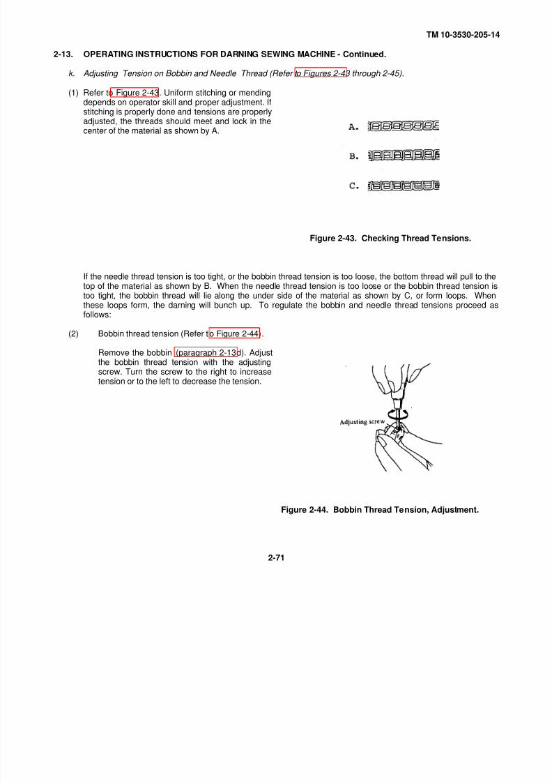
8/7/2019 TM 10-3530-205-10 CLOTHING REPAIR SHOP
http://slidepdf.com/reader/full/tm-10-3530-205-10-clothing-repair-shop 109/455
TM 10-3530-205-14
2-13. OPERATING INSTRUCTIONS FOR DARNING SEWING MACHINE - Continued.
k. Adjusting Tension on Bobbin and Needle Thread (Refer t o Figures 2-43 through 2-45).
(1) Refer to Figure 2-43 . Uniform stitching or mendingdepends on operator skill and proper adjustment. Ifstitching is properly done and tensions are properlyadjusted, the threads should meet and lock in thecenter of the material as shown by A.
Figure 2-43. Checking Thread Tensions.
If the needle thread tension is too tight, or the bobbin thread tension is too loose, the bottom thread will pull to thetop of the material as shown by B. When the needle thread tension is too loose or the bobbin thread tension istoo tight, the bobbin thread will lie along the under side of the material as shown by C, or form loops. Whenthese loops form, the darning will bunch up. To regulate the bobbin and needle thread tensions proceed asfollows:
(2) Bobbin thread tension (Refer t o Figure 2-44) .
Remove the bobbin (paragraph 2-13 d). Adjustthe bobbin thread tension with the adjustingscrew. Turn the screw to the right to increasetension or to the left to decrease the tension.
Figure 2-44. Bobbin Thread Tension, Adjustment.
2-71
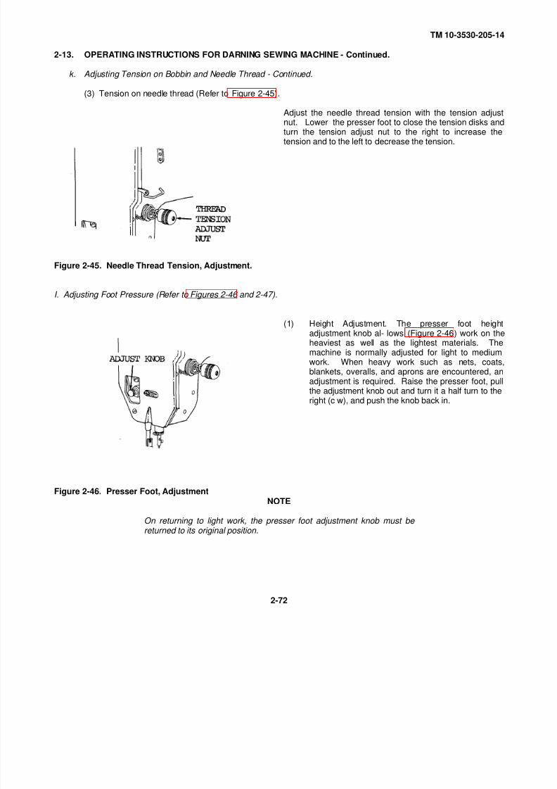
8/7/2019 TM 10-3530-205-10 CLOTHING REPAIR SHOP
http://slidepdf.com/reader/full/tm-10-3530-205-10-clothing-repair-shop 110/455
TM 10-3530-205-14
2-13. OPERATING INSTRUCTIONS FOR DARNING SEWING MACHINE - Continued.
k. Adjusting Tension on Bobbin and Needle Thread - Continued.
(3) Tension on needle thread (Refer to Figure 2-45) .
Figure 2-45. Needle Thread Tension, Adjustment.
Adjust the needle thread tension with the tension adjustnut. Lower the presser foot to close the tension disks andturn the tension adjust nut to the right to increase thetension and to the left to decrease the tension.
I. Adjusting Foot Pressure (Refer to Figures 2-46 and 2-47).
Figure 2-46. Presser Foot, Adjustment
(1) Height Adjustment. The presser foot heightadjustment knob al- lows (Figure 2-46 ) work on theheaviest as well as the lightest materials. Themachine is normally adjusted for light to mediumwork. When heavy work such as nets, coats,blankets, overalls, and aprons are encountered, an
adjustment is required. Raise the presser foot, pullthe adjustment knob out and turn it a half turn to theright (c w), and push the knob back in.
NOTE
On returning to light work, the presser foot adjustment knob must be returned to its original position.
2-72
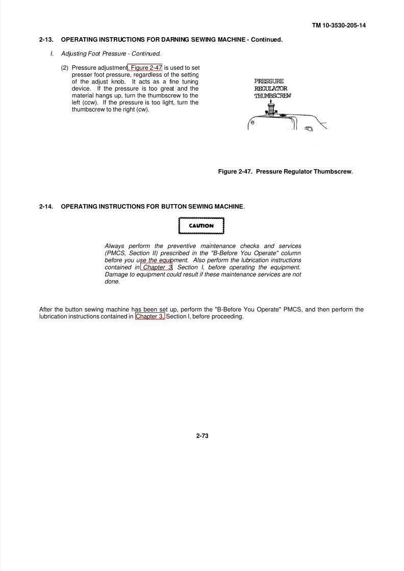
8/7/2019 TM 10-3530-205-10 CLOTHING REPAIR SHOP
http://slidepdf.com/reader/full/tm-10-3530-205-10-clothing-repair-shop 111/455
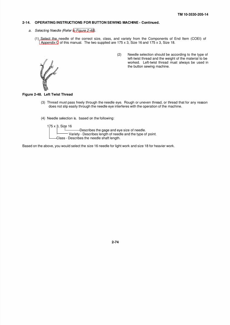
8/7/2019 TM 10-3530-205-10 CLOTHING REPAIR SHOP
http://slidepdf.com/reader/full/tm-10-3530-205-10-clothing-repair-shop 112/455
TM 10-3530-205-14
2-14. OPERATING INSTRUCTIONS FOR BUTTON SEWING MACHINE - Continued.
a. Selecting Needle (Refer t o Figure 2-48) .
(1) Select the needle of the correct size, class, and variety from the Components of End Item (COEI) ofAppendix C of this manual. The two supplied are 175 x 3, Size 16 and 175 x 3, Size 18.
Figure 2-48. Left Twist Thread
(2) Needle selection should be according to the type ofleft-twist thread and the weight of the material to beworked. Left-twist thread must always be used inthe button sewing machine.
(3) Thread must pass freely through the needle eye. Rough or uneven thread, or thread that for any reasondoes not slip easily through the needle eye interferes with the operation of the machine.
(4) Needle selection is. based on the following:
175 x 3, Size 16Describes the gage and eye size of needle.
Variety - Describes length of needle and the type of point.Class - Describes the needle shaft length.
Based on the above, you would select the size 16 needle for light work and size 18 for heavier work.
2-74
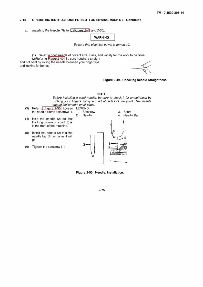
8/7/2019 TM 10-3530-205-10 CLOTHING REPAIR SHOP
http://slidepdf.com/reader/full/tm-10-3530-205-10-clothing-repair-shop 113/455
TM 10-3530-205-14
2-14. OPERATING INSTRUCTIONS FOR BUTTON SEWING MACHINE - Continued.
b. Installing the Needle (Refer t o Figures 2-49 and 2-50).
WARNING
Be sure that electrical power is turned off.
(1) Select a good needle of correct size, class, and variety for the work to be done.(2)Refer to Figure 2-49. Be sure needle is straight
and not bent by rolling the needle between your finger tipsand looking for bends.
Figure 2-49. Checking Needle Straightness.
NOTEBefore installing a used needle, be sure to check it for smoothness by rubbing your fingers lightly around all sides of the point. The needle should feel smooth on all sides.
(3) Refer to Figure 2-50. Loosenthe needle clamp setscrew(1).
(4) Hold the needle (2) so thatthe long groove on scarf (3) isin the front of the machine.
(5) Install the needle (2) into theneedle bar (4) as far as it willgo.
(6) Tighten the setscrew (1)
LEGEND1. Setscrew 3. Scarf2. Needle 4. Needle Bar
Figure 2-50. Needle, Installation.
2-75
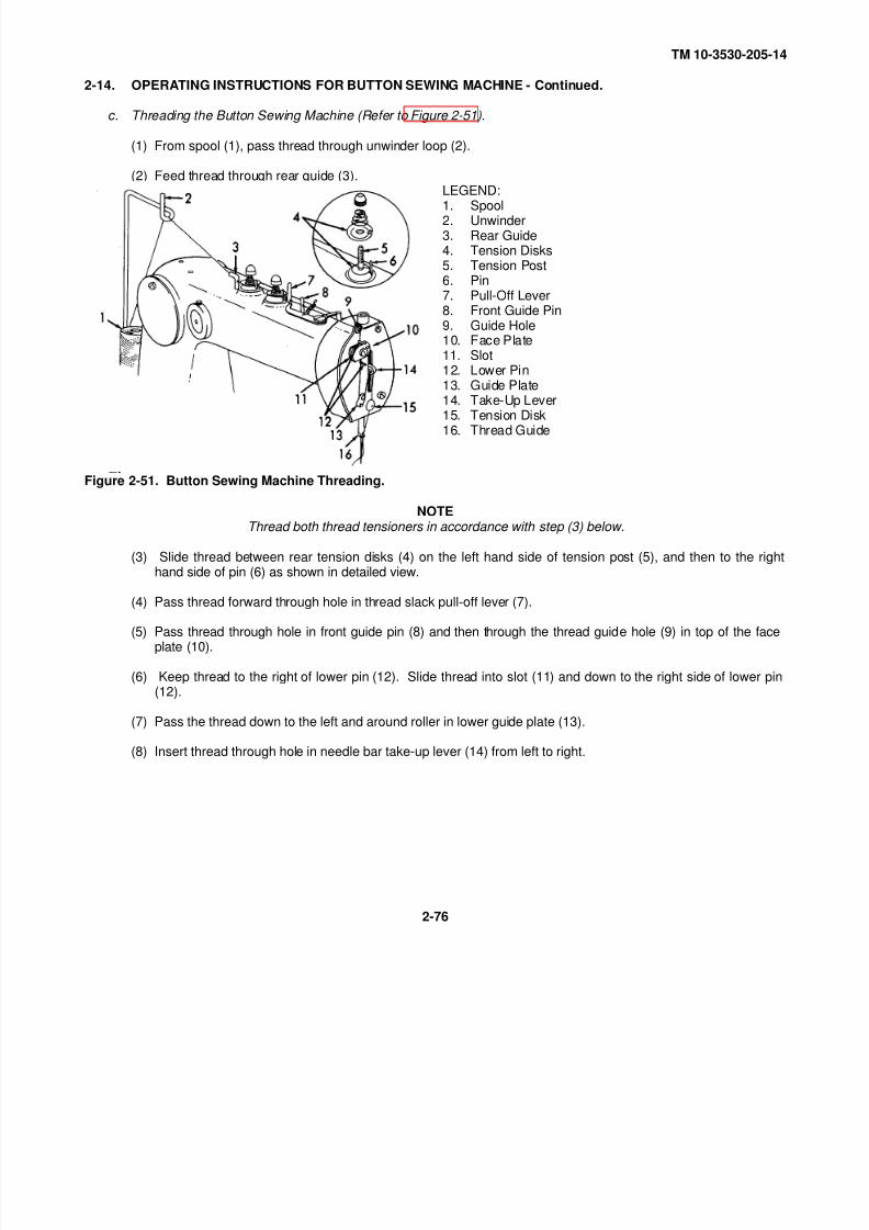
8/7/2019 TM 10-3530-205-10 CLOTHING REPAIR SHOP
http://slidepdf.com/reader/full/tm-10-3530-205-10-clothing-repair-shop 114/455
TM 10-3530-205-14
2-14. OPERATING INSTRUCTIONS FOR BUTTON SEWING MACHINE - Continued.
c. Threading the Button Sewing Machine (Refer to Figure 2-51) .
(1) From spool (1), pass thread through unwinder loop (2).
(2) Feed thread through rear guide (3).LEGEND:1. Spool2. Unwinder3. Rear Guide4. Tension Disks5. Tension Post6. Pin7. Pull-Off Lever8. Front Guide Pin9. Guide Hole10. Face Plate11. Slot12. Lower Pin13. Guide Plate14. Take-Up Lever15. Tension Disk16. Thread Guide
Figure 2-51. Button Sewing Machine Threading.
NOTEThread both thread tensioners in accordance with step (3) below.
(3) Slide thread between rear tension disks (4) on the left hand side of tension post (5), and then to the righthand side of pin (6) as shown in detailed view.
(4) Pass thread forward through hole in thread slack pull-off lever (7).
(5) Pass thread through hole in front guide pin (8) and then through the thread guide hole (9) in top of the faceplate (10).
(6) Keep thread to the right of lower pin (12). Slide thread into slot (11) and down to the right side of lower pin(12).
(7) Pass the thread down to the left and around roller in lower guide plate (13).
(8) Insert thread through hole in needle bar take-up lever (14) from left to right.
2-76
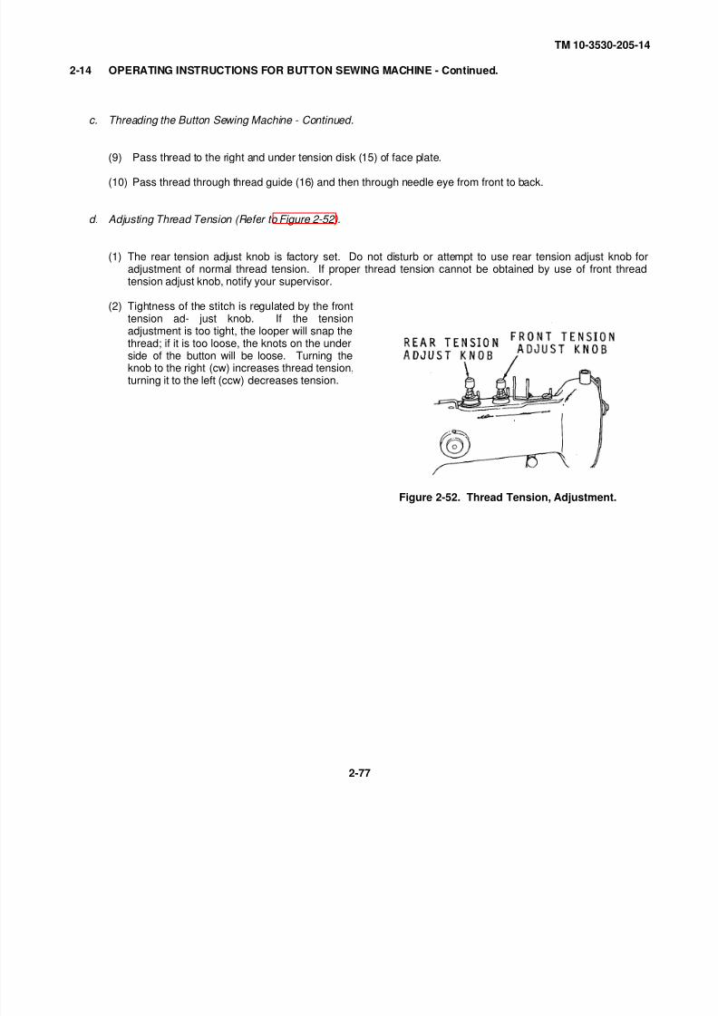
8/7/2019 TM 10-3530-205-10 CLOTHING REPAIR SHOP
http://slidepdf.com/reader/full/tm-10-3530-205-10-clothing-repair-shop 115/455
TM 10-3530-205-14
2-14 OPERATING INSTRUCTIONS FOR BUTTON SEWING MACHINE - Continued.
c. Threading the Button Sewing Machine - Continued.
(9) Pass thread to the right and under tension disk (15) of face plate.
(10) Pass thread through thread guide (16) and then through needle eye from front to back.
d. Adjusting Thread Tension (Refer to Figure 2-52) .
(1) The rear tension adjust knob is factory set. Do not disturb or attempt to use rear tension adjust knob foradjustment of normal thread tension. If proper thread tension cannot be obtained by use of front threadtension adjust knob, notify your supervisor.
(2) Tightness of the stitch is regulated by the fronttension ad- just knob. If the tensionadjustment is too tight, the looper will snap thethread; if it is too loose, the knots on the underside of the button will be loose. Turning theknob to the right (cw) increases thread tension,turning it to the left (ccw) decreases tension.
Figure 2-52. Thread Tension, Adjustment.
2-77
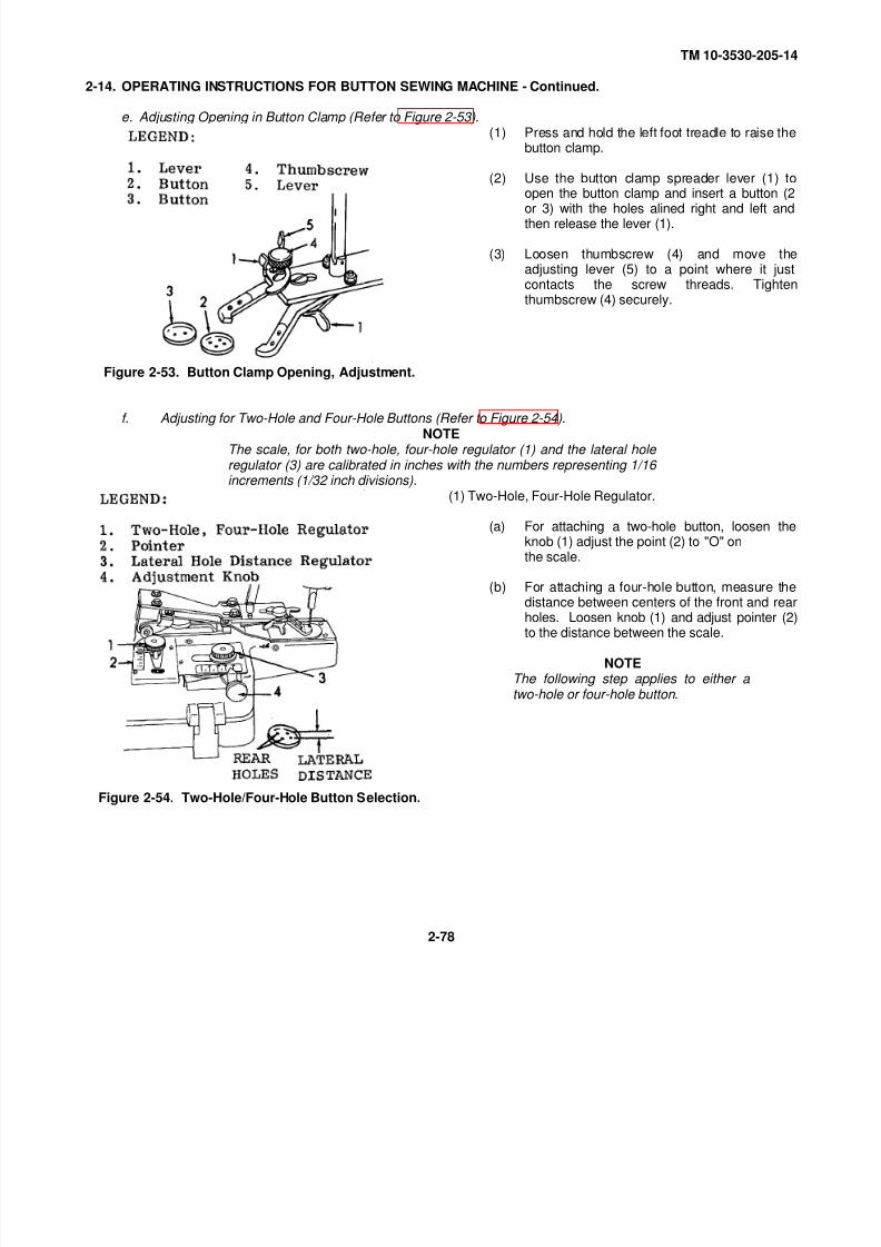
8/7/2019 TM 10-3530-205-10 CLOTHING REPAIR SHOP
http://slidepdf.com/reader/full/tm-10-3530-205-10-clothing-repair-shop 116/455
TM 10-3530-205-14
2-14. OPERATING INSTRUCTIONS FOR BUTTON SEWING MACHINE - Continued.
e. Adjusting Opening in Button Clamp (Refer to Figure 2-53) .
Figure 2-53. Button Clamp Opening, Adjustment.
(1) Press and hold the left foot treadle to raise thebutton clamp.
(2) Use the button clamp spreader lever (1) toopen the button clamp and insert a button (2or 3) with the holes alined right and left andthen release the lever (1).
(3) Loosen thumbscrew (4) and move theadjusting lever (5) to a point where it justcontacts the screw threads. Tightenthumbscrew (4) securely.
f. Adjusting for Two-Hole and Four-Hole Buttons (Refer t o Figure 2-54) .NOTE
The scale, for both two-hole, four-hole regulator (1) and the lateral hole regulator (3) are calibrated in inches with the numbers representing 1/16 increments (1/32 inch divisions).
Figure 2-54. Two-Hole/Four-Hole Button Selection.
(1) Two-Hole, Four-Hole Regulator.
(a) For attaching a two-hole button, loosen theknob (1) adjust the point (2) to "O" onthe scale.
(b) For attaching a four-hole button, measure the
distance between centers of the front and rearholes. Loosen knob (1) and adjust pointer (2)to the distance between the scale.
NOTEThe following step applies to either a two-hole or four-hole button .
2-78
8/7/2019 TM 10-3530-205-10 CLOTHING REPAIR SHOP
http://slidepdf.com/reader/full/tm-10-3530-205-10-clothing-repair-shop 117/455
TM 10-3530-205-14
2-14. OPERATING INSTRUCTIONS FOR BUTTON SEWING MACHINE - Continued.
f. Adjusting for Two-Hole and Four-Hole Buttons - Continued.
(2) Lateral Distance. Measure the distance between the button hole centers. Loosen the knob (3) and adjustthe regulator (4) for this distance on the scale.
NOTE
Be sure the button typo end hole distances have been correctly adjusted (step f) before proceeding.
g. Operating the Button Sewing Machine.
(1) Inserting Button and Material in Machine.
(a) Depress the left foot treadle to raise the button clamp enough to insert the button in the jaws of theclamp. While the clamp is raised, insert the material between the clamp and the feed plate.
(b) Release the treadle.
(2) Turning on Power Source. Set motor switch to the ON position.
(3) Sewing Button on Material.
(a) Using a quick firm tread push down on the right treadle to its stop and quickly release it. Do not hold thetreadle down after the machine has been started.
(b) The machine will automatically make its cycl e of 16 stitches and stop with the needle raised to its highestposition.
WARNING
Do not raise the button. clamp until the machine has stopped as a broken needle may result and cause injury to personnel.
(4) Removing Material from Machine.
(a) Press firmly on the left foot treadle to raise the clamp.This step cuts the thread from the looper under the needle.
(b) Pull the attached button sewn from the jaws of the button clamp.
(5) Set motor switch to the OFF position.
2-79
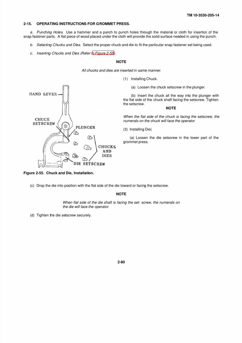
8/7/2019 TM 10-3530-205-10 CLOTHING REPAIR SHOP
http://slidepdf.com/reader/full/tm-10-3530-205-10-clothing-repair-shop 118/455
TM 10-3530-205-14
2-15. OPERATING INSTRUCTIONS FOR GROMMET PRESS.
a. Punching Holes . Use a hammer and a punch to punch holes through the material or cloth for insertion of thesnap fastener parts. A flat piece of wood placed under the cloth will provide the solid surface needed in using the punch.
b. Selecting Chucks and Dies. Select the proper chuck and die to fit the particular snap fastener set being used.
c. Inserting Chucks and Dies (Refer to Figure 2-55) .
NOTE
All chucks and dies are inserted in same manner .
Figure 2-55. Chuck and Die, Installation.
(1) Installing Chuck.
(a) Loosen the chuck setscrew in the plunger.
(b) Insert the chuck all the way into the plunger withthe flat side of the chuck shaft facing the setscrew. Tightenthe setscrew.
NOTE
When the flat side of the chuck is facing the setscrew, the numerals on the chuck will face the operator.
(3) Installing Die(
(a) Loosen the die setscrew in the lower part of thegrommet press.
(c) Drop the die into position with the flat side of the die toward or facing the setscrew.
NOTE
When flat side of the die shaft is facing the set- screw, the numerals on the die will face the operator.
(d) Tighten the die setscrew securely.
2-80
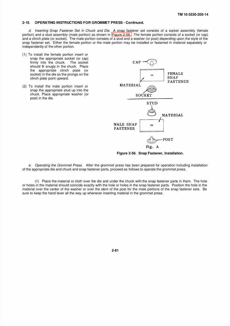
8/7/2019 TM 10-3530-205-10 CLOTHING REPAIR SHOP
http://slidepdf.com/reader/full/tm-10-3530-205-10-clothing-repair-shop 119/455
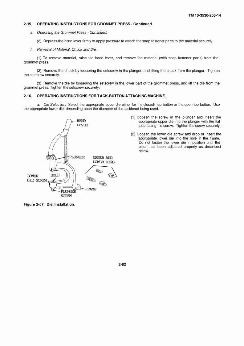
8/7/2019 TM 10-3530-205-10 CLOTHING REPAIR SHOP
http://slidepdf.com/reader/full/tm-10-3530-205-10-clothing-repair-shop 120/455
TM 10-3530-205-14
2-15. OPERATING INSTRUCTIONS FOR GROMMET PRESS - Continued.
e. Operating the Grommet Press - Continued.
(2) Depress the hand lever firmly to apply pressure to attach the snap fastener parts to the material securely.
f. Removal of Material, Chuck and Die.
(1) To remove material, raise the hand lever, and remove the material (with snap fastener parts) from thegrommet press.
(2) Remove the chuck by loosening the setscrew in the plunger, and lifting the chuck from the plunger. Tightenthe setscrew securely.
(3) Remove the die by loosening the setscrew in the lower part of the grommet press, and lift the die from thegrommet press. Tighten the setscrew securely.
2-16. OPERATING INSTRUCTIONS FOR TACK-BUTTON ATTACHING MACHINE .
a. Die Selection . Select the appropriate upper die either for the closed- top button or the open-top button. Usethe appropriate lower die, depending upon the diameter of the tackhead being used.
Figure 2-57. Die, Installation.
(1) Loosen the screw in the plunger and insert theappropriate upper die into the plunger with the flatside facing the screw. Tighten the screw securely.
(2) Loosen the lower die screw and drop or insert theappropriate lower die into the hole in the frame.Do not fasten the lower die in position until thepinch has been adjusted properly as describedbelow.
2-82
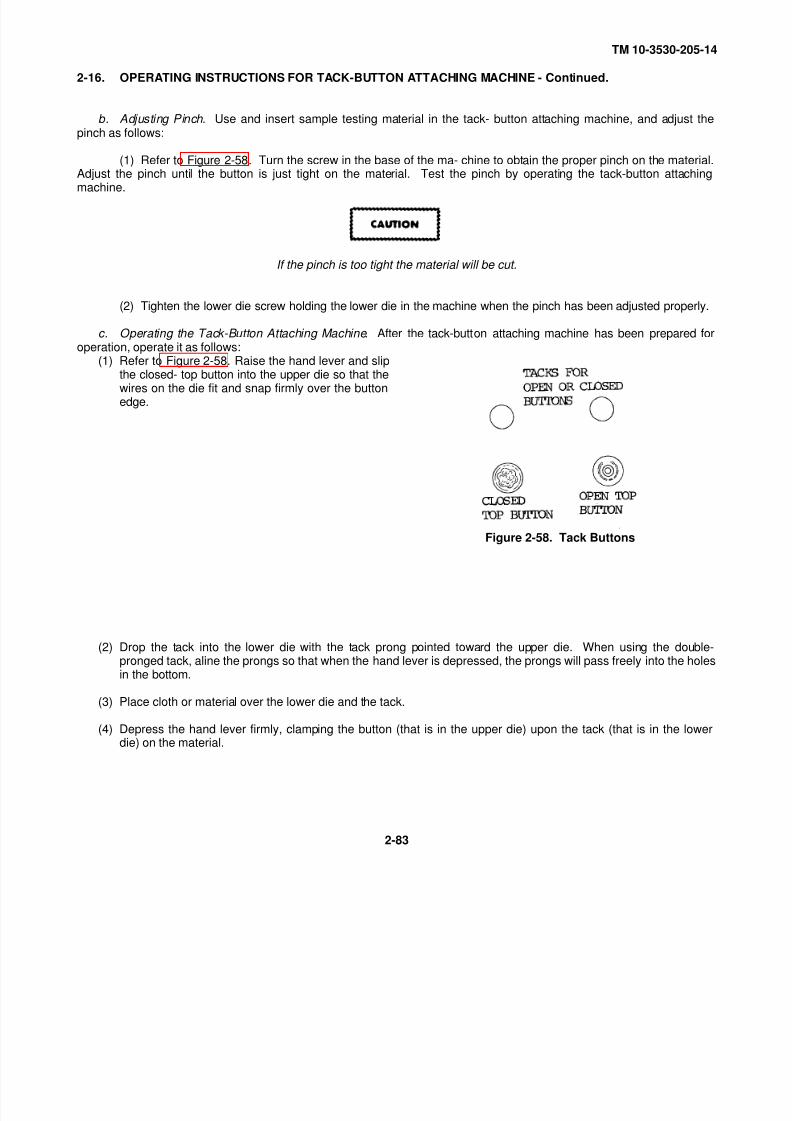
8/7/2019 TM 10-3530-205-10 CLOTHING REPAIR SHOP
http://slidepdf.com/reader/full/tm-10-3530-205-10-clothing-repair-shop 121/455
TM 10-3530-205-14
2-16. OPERATING INSTRUCTIONS FOR TACK-BUTTON ATTACHING MACHINE - Continued.
b. Adjusting Pinch . Use and insert sample testing material in the tack- button attaching machine, and adjust thepinch as follows:
(1) Refer to Figure 2-58 . Turn the screw in the base of the ma- chine to obtain the proper pinch on the material.Adjust the pinch until the button is just tight on the material. Test the pinch by operating the tack-button attachingmachine.
If the pinch is too tight the material will be cut.
(2) Tighten the lower die screw holding the lower die in the machine when the pinch has been adjusted properly.
c. Operating the Tack-Button Attaching Machine . After the tack-button attaching machine has been prepared foroperation, operate it as follows:
(1) Refer to Figure 2-58. Raise the hand lever and slipthe closed- top button into the upper die so that thewires on the die fit and snap firmly over the buttonedge.
Figure 2-58. Tack Buttons
(2) Drop the tack into the lower die with the tack prong pointed toward the upper die. When using the double-pronged tack, aline the prongs so that when the hand lever is depressed, the prongs will pass freely into the holesin the bottom.
(3) Place cloth or material over the lower die and the tack.
(4) Depress the hand lever firmly, clamping the button (that is in the upper die) upon the tack (that is in the lowerdie) on the material.
2-83
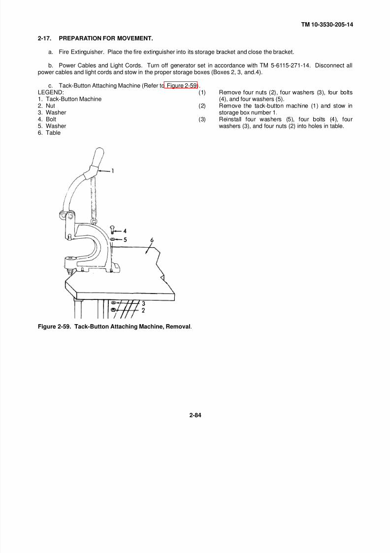
8/7/2019 TM 10-3530-205-10 CLOTHING REPAIR SHOP
http://slidepdf.com/reader/full/tm-10-3530-205-10-clothing-repair-shop 122/455
TM 10-3530-205-14
2-17. PREPARATION FOR MOVEMENT.
a. Fire Extinguisher. Place the fire extinguisher into its storage bracket and close the bracket.
b. Power Cables and Light Cords. Turn off generator set in accordance with TM 5-6115-271-14. Disconnect allpower cables and light cords and stow in the proper storage boxes (Boxes 2, 3, and.4).
c. Tack-Button Attaching Machine (Refer to Figure 2-59) .LEGEND:1. Tack-Button Machine2. Nut3. Washer4. Bolt5. Washer6. Table
Figure 2-59. Tack-Button Attaching Machine, Removal .
(1) Remove four nuts (2), four washers (3), four bolts(4), and four washers (5).
(2) Remove the tack-button machine (1) and stow instorage box number 1.
(3) Reinstall four washers (5), four bolts (4), fourwashers (3), and four nuts (2) into holes in table.
2-84
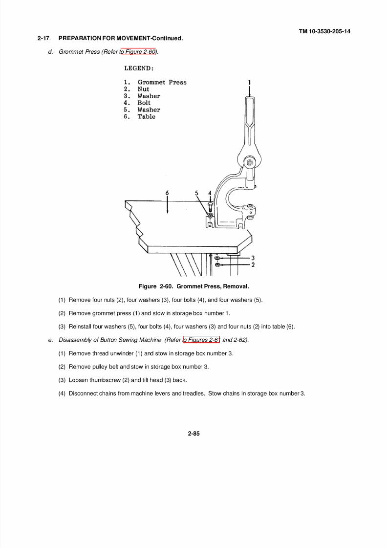
8/7/2019 TM 10-3530-205-10 CLOTHING REPAIR SHOP
http://slidepdf.com/reader/full/tm-10-3530-205-10-clothing-repair-shop 123/455
TM 10-3530-205-142-17. PREPARATION FOR MOVEMENT-Continued.
d. Grommet Press (Refer t o Figure 2-60) .
Figure 2-60. Grommet Press, Removal.
(1) Remove four nuts (2), four washers (3), four bolts (4), and four washers (5).
(2) Remove grommet press (1) and stow in storage box number 1.
(3) Reinstall four washers (5), four bolts (4), four washers (3) and four nuts (2) into table (6).
e. Disassembly of Button Sewing Machine (Refer t o Figures 2-61 and 2-62).
(1) Remove thread unwinder (1) and stow in storage box number 3.
(2) Remove pulley belt and stow in storage box number 3.
(3) Loosen thumbscrew (2) and tilt head (3) back.
(4) Disconnect chains from machine levers and treadles. Stow chains in storage box number 3.
2-85
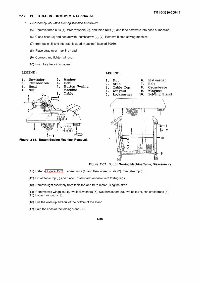
8/7/2019 TM 10-3530-205-10 CLOTHING REPAIR SHOP
http://slidepdf.com/reader/full/tm-10-3530-205-10-clothing-repair-shop 124/455
TM 10-3530-205-142-17. PREPARATION FOR MOVEMENT-Continued.
e. Disassembly of Button Sewing Machine-Continued.
(5) Remove three nuts (4), three washers (5), and three bolts (5) and tape hardware into base of machine.
(6) Close head (3) and secure with thumbscrew (2). (7) Remove button sewing machine
(7) from table (8) and into tray (located in cabinet) labeled 60010.
(8) Place strap over machine head.
(9) Connect and tighten wingnut.
(10) Push tray back into cabinet.
Figure 2-61. Button Sewing Machine, Removal.
Figure 2-62. Button Sewing Machine Table, Disassembly .
(11) Refer to Figure 2-62 . Loosen nuts (1) and then loosen studs (2) from table top (3).
(12) Lift off table top (3) and place upside down on table with folding legs.
(13) Remove light assembly from table top and fix to motor using the strap.
(14) Remove two wingnuts (4), two lockwashers (5), two flatwashers (6), two bolts (7), and crossbrace (8).(15) Loosen wingnuts (9).
(16) Pull the ends up and out of the bottom of the stand.
(17) Fold the ends of the folding stand (10).
2-86
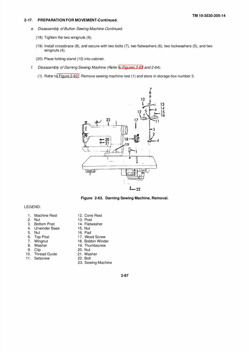
8/7/2019 TM 10-3530-205-10 CLOTHING REPAIR SHOP
http://slidepdf.com/reader/full/tm-10-3530-205-10-clothing-repair-shop 125/455
TM 10-3530-205-142-17. PREPARATION FOR MOVEMENT-Continued.
e. Disassembly of Button Sewing Machine-Continued.
(18) Tighten the two wingnuts (9).
(19) Install crossbrace (8), and secure with two bolts (7), two flatwashers (6), two lockwashers (5), and twowingnuts (4).
(20) Place folding stand (10) into cabinet.
f. Disassembly of Darning Sewing Machine (Refer t o Figures 2-63 and 2-64).
(1) Refer to Figure 2-63. Remove sewing machine rest (1) and store in storage box number 3.
Figure 2-63. Darning Sewing Machine, Removal.
LEGEND:
1. Machine Rest 12. Cone Rest2. Nut 13. Post3. Bottom Post 14. Flatwasher4. Unwinder Base 15. Nut5. Nut 16. Pad6. Top Post 17. Wood Screw7. Wingnut 18. Bobbin Winder8. Washer 19. Thumbscrew9. Clip 20. Nut
10. Thread Guide 21. Washer11. Setscrew 22. Bolt
23. Sewing Machine
2-87
8/7/2019 TM 10-3530-205-10 CLOTHING REPAIR SHOP
http://slidepdf.com/reader/full/tm-10-3530-205-10-clothing-repair-shop 126/455
TM 10-3530-205-14
2-17. PREPARATION FOR MOVEMENT-Continued.
f. Disassembly of Darning Sewing Machine-Continued.
(2) Loosen nut (2) and remove bottom post (3) from unwinder base (4).
(3) Loosen nut (5) and remove top post (6) from bottom post (3).
(4) Remove wingnut (7), washer (8), clip (9), and thread guides (10).
(5) Loosen setscrew (11) and remove cone rest (12) from bottom post (3).
(6) Remove two posts (13), two flatwashers (14), two nuts (15), two pads (16), and cone rest (12).
(7) Stow all parts of thread unwinder base in storage box number 3.
(8) Remove three wood screws (17) and bobbin winder (18). Stow bobbin winder in storage box number 3.
(9) Loosen thumbscrew (19) and tilt head back.
(10) Remove pulley belt and stow in storage box number 3.
(11) Remove light assembly from table top and strap to motor with strap provided.
(12) Remove three nuts (20), three washers (21), and three bolts (22). Stow hardware into sewing machine (23)base.
(13) Close machine head and secure with thumbscrew (19).
(14) Place sewing machine head into tray labeled 678HD.
(15) Fold strap over machine head.
(16) Connect and tighten wingnut.
(17) Push tray back into cabinet.
(18) Refer to Figure 2-64. Disconnect treadle rod (1) from clutch arm (2).
2-88
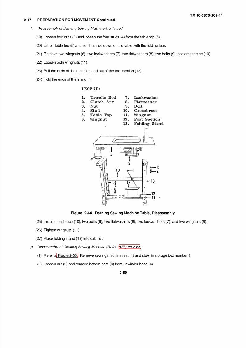
8/7/2019 TM 10-3530-205-10 CLOTHING REPAIR SHOP
http://slidepdf.com/reader/full/tm-10-3530-205-10-clothing-repair-shop 127/455
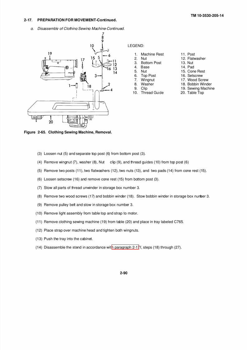
8/7/2019 TM 10-3530-205-10 CLOTHING REPAIR SHOP
http://slidepdf.com/reader/full/tm-10-3530-205-10-clothing-repair-shop 128/455
TM 10-3530-205-142-17. PREPARATION FOR MOVEMENT-Continued.
g. Disassembly of Clothing Sewing Machine-Continued.
LEGEND:
1. Machine Rest 11. Post2. Nut 12. Flatwasher3. Bottom Post 13. Nut4. Base 14. Pad5. Nut 15. Cone Rest6. Top Post 16. Setscrew7. Wingnut 17. Wood Screw8. Washer 18. Bobbin Winder9. Clip 19. Sewing Machine
10. Thread Guide 20. Table Top
Figure 2-65. Clothing Sewing Machine, Removal.
(3) Loosen nut (5) and separate top post (6) from bottom post (3).
(4) Remove wingnut (7), washer (8), Nut clip (9), and thread guides (10) from top post (6)
(5) Remove two posts (11), two flatwashers (12), two nuts (13), and two pads (14) from cone rest (15).
(6) Loosen setscrew (16) and remove cone rest (15) from bottom post (3).
(7) Stow all parts of thread unwinder in storage box number 3.
(8) Remove two wood screws (17) and bobbin winder (18). Stow bobbin winder in storage box number 3.
(9) Remove pulley belt and stow in storage box number 3.
(10) Remove light assembly from table top and strap to motor.
(11) Remove clothing sewing machine (19) from table (20) and place in tray labeled C765.
(12) Place strap over machine head and tighten both wingnuts.
(13) Push the tray into the cabinet.
(14) Disassemble the stand in accordance wit h paragraph 2-17 f, steps (18) through (27).
2-90
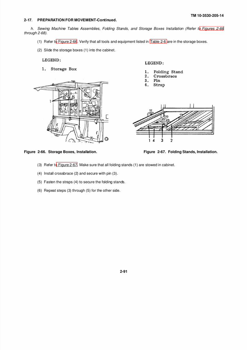
8/7/2019 TM 10-3530-205-10 CLOTHING REPAIR SHOP
http://slidepdf.com/reader/full/tm-10-3530-205-10-clothing-repair-shop 129/455
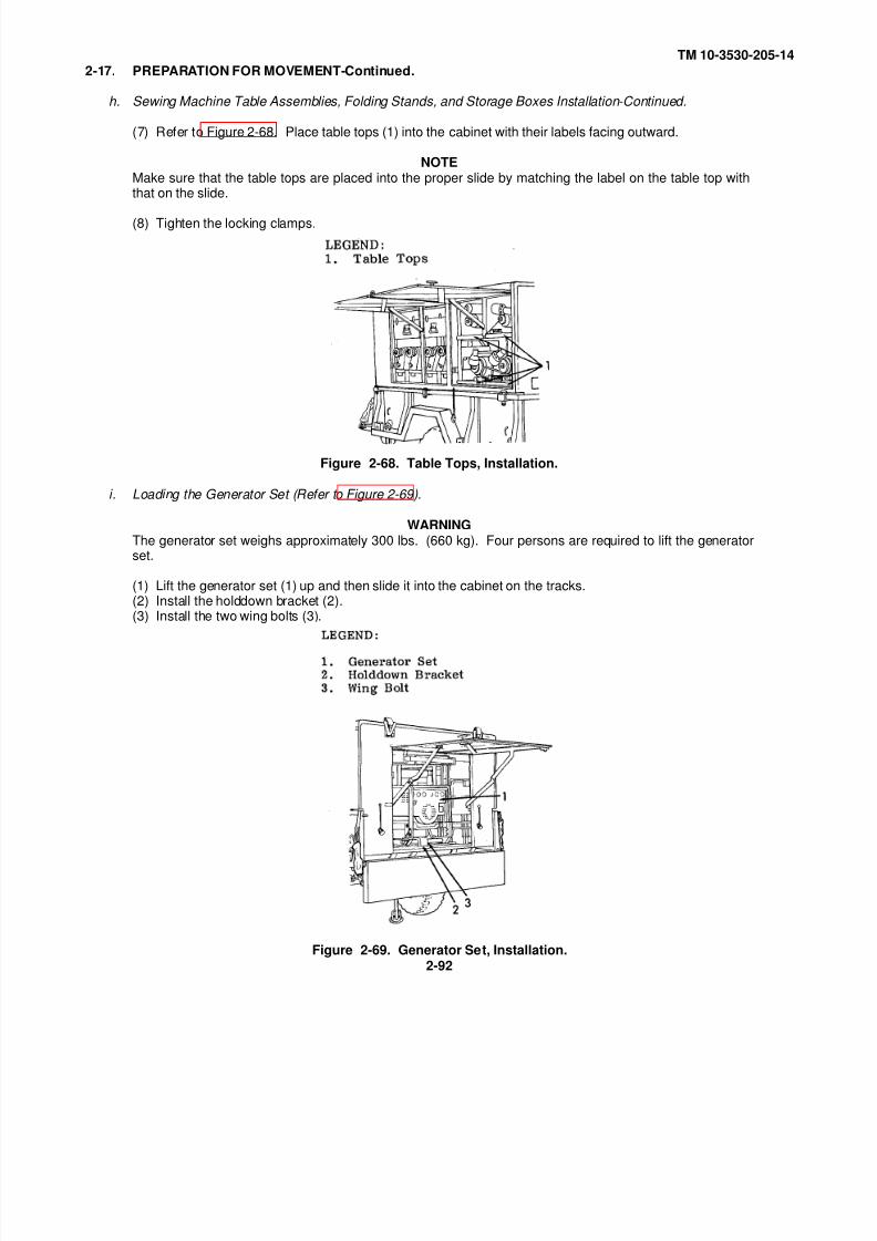
8/7/2019 TM 10-3530-205-10 CLOTHING REPAIR SHOP
http://slidepdf.com/reader/full/tm-10-3530-205-10-clothing-repair-shop 130/455
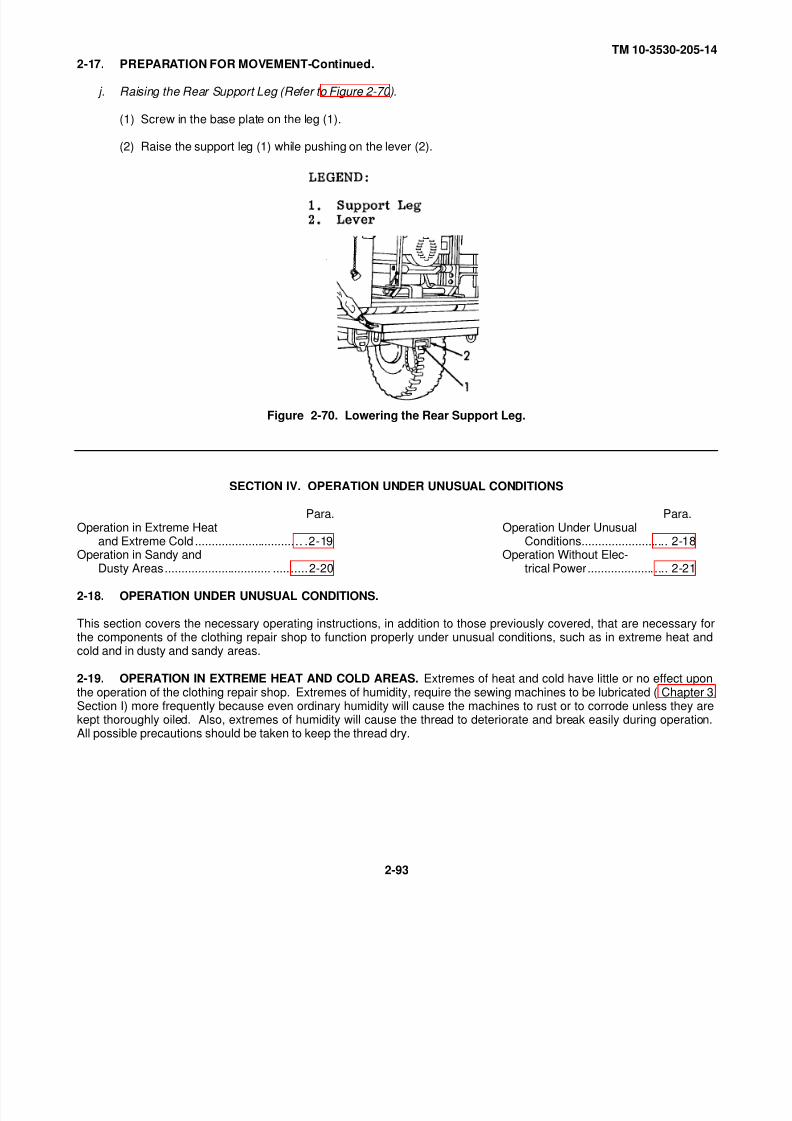
8/7/2019 TM 10-3530-205-10 CLOTHING REPAIR SHOP
http://slidepdf.com/reader/full/tm-10-3530-205-10-clothing-repair-shop 131/455
TM 10-3530-205-142-17. PREPARATION FOR MOVEMENT-Continued.
j. Raising the Rear Support Leg (Refer to Figure 2-70) .
(1) Screw in the base plate on the leg (1).
(2) Raise the support leg (1) while pushing on the lever (2).
Figure 2-70. Lowering the Rear Support Leg.
SECTION IV. OPERATION UNDER UNUSUAL CONDITIONS
Para. Para.Operation in Extreme Heat Operation Under Unusual
and Extreme Cold .............................. .. .2-19 Conditions...................... .... 2-18Operation in Sandy and Operation Without Elec-Dusty Areas................................ ..... .....2-20 trical Power.................... .... 2-21
2-18. OPERATION UNDER UNUSUAL CONDITIONS.
This section covers the necessary operating instructions, in addition to those previously covered, that are necessary forthe components of the clothing repair shop to function properly under unusual conditions, such as in extreme heat andcold and in dusty and sandy areas.
2-19. OPERATION IN EXTREME HEAT AND COLD AREAS. Extremes of heat and cold have little or no effect uponthe operation of the clothing repair shop. Extremes of humidity, require the sewing machines to be lubricated ( Chapter 3,Section I) more frequently because even ordinary humidity will cause the machines to rust or to corrode unless they are
kept thoroughly oiled. Also, extremes of humidity will cause the thread to deteriorate and break easily during operation.All possible precautions should be taken to keep the thread dry.
2-93
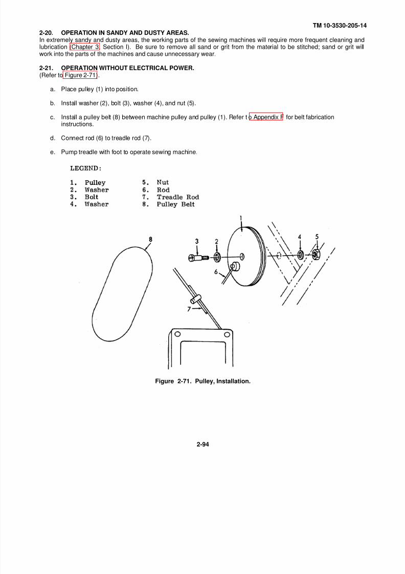
8/7/2019 TM 10-3530-205-10 CLOTHING REPAIR SHOP
http://slidepdf.com/reader/full/tm-10-3530-205-10-clothing-repair-shop 132/455
TM 10-3530-205-142-20. OPERATION IN SANDY AND DUSTY AREAS.In extremely sandy and dusty areas, the working parts of the sewing machines will require more frequent cleaning andlubrication (Chapter 3, Section I). Be sure to remove all sand or grit from the material to be stitched; sand or grit willwork into the parts of the machines and cause unnecessary wear.
2-21. OPERATION WITHOUT ELECTRICAL POWER.(Refer to Figure 2-71) .
a. Place pulley (1) into position.
b. Install washer (2), bolt (3), washer (4), and nut (5).
c. Install a pulley belt (8) between machine pulley and pulley (1). Refer t o Appendix F for belt fabricationinstructions.
d. Connect rod (6) to treadle rod (7).
e. Pump treadle with foot to operate sewing machine.
Figure 2-71 . Pulley, Installation.
2-94
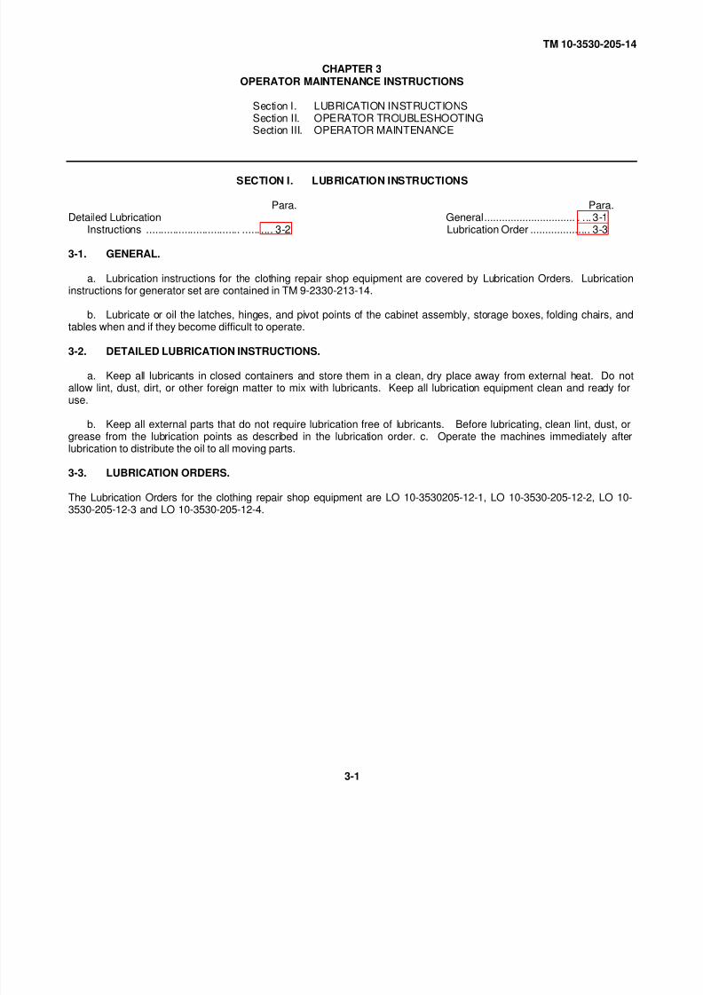
8/7/2019 TM 10-3530-205-10 CLOTHING REPAIR SHOP
http://slidepdf.com/reader/full/tm-10-3530-205-10-clothing-repair-shop 133/455
TM 10-3530-205-14
CHAPTER 3OPERATOR MAINTENANCE INSTRUCTIONS
Section I. LUBRICATION INSTRUCTIONSSection II. OPERATOR TROUBLESHOOTINGSection III. OPERATOR MAINTENANCE
SECTION I. LUBRICATION INSTRUCTIONS
Para. Para.Detailed Lubrication General............................... . ... 3-1
Instructions ................................ ...... .... 3-2 Lubrication Order ................ .... 3-3
3-1. GENERAL.
a. Lubrication instructions for the clothing repair shop equipment are covered by Lubrication Orders. Lubricationinstructions for generator set are contained in TM 9-2330-213-14.
b. Lubricate or oil the latches, hinges, and pivot points of the cabinet assembly, storage boxes, folding chairs, andtables when and if they become difficult to operate.
3-2. DETAILED LUBRICATION INSTRUCTIONS.
a. Keep all lubricants in closed containers and store them in a clean, dry place away from external heat. Do notallow lint, dust, dirt, or other foreign matter to mix with lubricants. Keep all lubrication equipment clean and ready foruse.
b. Keep all external parts that do not require lubrication free of lubricants. Before lubricating, clean lint, dust, orgrease from the lubrication points as described in the lubrication order. c. Operate the machines immediately afterlubrication to distribute the oil to all moving parts.
3-3. LUBRICATION ORDERS.
The Lubrication Orders for the clothing repair shop equipment are LO 10-3530205-12-1, LO 10-3530-205-12-2, LO 10-3530-205-12-3 and LO 10-3530-205-12-4.
3-1
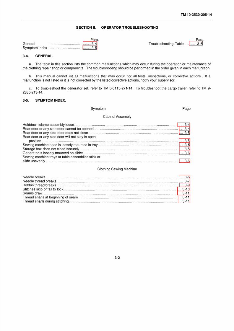
8/7/2019 TM 10-3530-205-10 CLOTHING REPAIR SHOP
http://slidepdf.com/reader/full/tm-10-3530-205-10-clothing-repair-shop 134/455
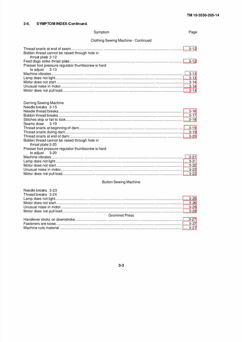
8/7/2019 TM 10-3530-205-10 CLOTHING REPAIR SHOP
http://slidepdf.com/reader/full/tm-10-3530-205-10-clothing-repair-shop 135/455
TM 10-3530-205-14
3-5. SYMPTOM INDEX-Continued.
Symptom Page
Clothing Sewing Machine - Continued
Thread snarls at end of seam................................ ................................ ................................ ............ .....3-12Bobbin thread cannot be raised through hole in
throat plate 3-12Feed dogs strike throat plate ................................ ................................ ................................ ............. .....3-12Presser foot pressure regulator thumbscrew is hard
to adjust 3-13Machine vibrates................................ ................................ ................................ ................................ ....3-13Lamp does not light................................ ................................ ................................ ........................... ..... 3-13Motor does not start ................................ ................................ ................................ ........................... .... 3-14Unusual noise in motor................................ ................................ ................................ ....................... .... 3-14Motor does not pull load................................ ................................ ................................ ..................... .... 3-14
Darning Sewing MachineNeedle breaks 3-15Needle thread breaks................................ ................................ ................................ ........................ ..... 3-16Bobbin thread breaks ................................ ................................ ................................ ........................ ..... 3-17Stitches skip or fail to lock................................ ................................ ................................ ................. .....3-18Seams draw 3-19Thread snarls at beginning of darn................................ ................................ ................................ ..... ....3-19Thread snarls during darn................................ ................................ ................................ ................... ....3-19Thread snarls at end of darn................................ ................................ ................................ .............. ..... 3-20Bobbin thread cannot be raised through hole in
throat plate:3-20Presser foot pressure regulator thumbscrew is hard
to adjust 3-20Machine vibrates................................ ................................ ................................ ................................ ....3-21Lamp does not light................................ ................................ ................................ ........................... ..... 3-21
Motor does not start ................................ ................................ ................................ .......................... ..... 3-22Unusual noise in motor................................ ................................ ................................ ...................... ..... 3-22Motor does not pull load................................ ................................ ................................ .................... ..... 3-22
Button Sewing Machine
Needle breaks 3-23Thread breaks 3-24Lamp does not light................................ ................................ ................................ ........................... ..... 3-25Motor does not start ................................ ................................ ................................ .......................... ..... 3-26Unusual noise in motor................................ ................................ ................................ ...................... ..... 3-26Motor does not pull load................................ ................................ ................................ .................... ..... 3-26
Grommet Press
Handlever sticks on downstroke................................ ................................ ................................ ........ .....3-27Fasteners are loose................................ ................................ ................................ ........................... ..... 3-27Machine cuts material ................................ ................................ ................................ ....................... ..... 3-27
3-3
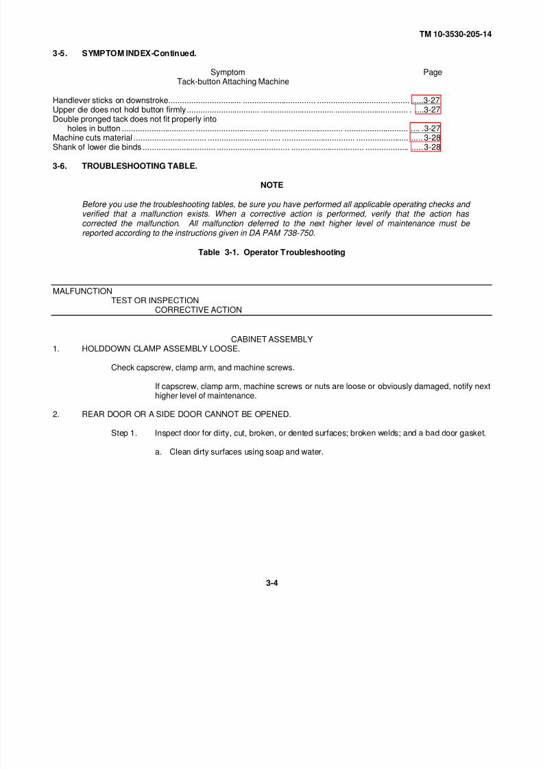
8/7/2019 TM 10-3530-205-10 CLOTHING REPAIR SHOP
http://slidepdf.com/reader/full/tm-10-3530-205-10-clothing-repair-shop 136/455
8/7/2019 TM 10-3530-205-10 CLOTHING REPAIR SHOP
http://slidepdf.com/reader/full/tm-10-3530-205-10-clothing-repair-shop 137/455
TM 10-3530-205-14
Table 3-1. Operator Troubleshooting-Continued
MALFUNCTIONTEST OR INSPECTION
CORRECTIVE ACTION
CABINET ASSEMBLY
b. Notify next higher level of maintenance for cut, broken, dented surfaces or welds, andbad door gasket.
Step 2. Check that folding handle lock is not bent, broken, loosely mounted or missing. If foldinghand lock is defective or missing, notify next higher level of maintenance.
Step 3. Check that door hinge is not broken or bent. If door hinge is broken or bent, notify nexthigher level of maintenance.
3. REAR DOOR OR SIDE DOOR DOES NOT CLOSE.Inspect door for the same defects as malfunction No. 2.
4. REAR OR SIDE DOOR WILL NOT STAY IN OPEN POSITION.Check door stays for mechanical binding and loose or missing door stay mounting brackets.
Notify next higher level of maintenance if door stays will not lock into position due to bindingor loose or missing mounting brackets.
5. SEWING MACHINE HIEAD IS LOOSELY MOUNTED IN TRAY.
Step 1. Check that tray strap assembly holddown thumbscrew is tight.
Tighten thumbscrew.
Step 2. Check that tray strap assembly hinge (on tray) is not loosely mounted.
If strap assembly is loose, notify next higher level of maintenance.6. STORAGE BOX DOES NOT CLOSE SECURELY.
Step 1. Check that storage box hinge is not bent or broken.
If hinge is bent or broken, notify next higher level of maintenance.
3-5
8/7/2019 TM 10-3530-205-10 CLOTHING REPAIR SHOP
http://slidepdf.com/reader/full/tm-10-3530-205-10-clothing-repair-shop 138/455
TM 10-3530-205-14
Table 3-1. Operator Troubleshooting-Continued
MALFUNCTIONTEST OR INSPECTION
CORRECTIVE ACTION
CABINET ASSEMBLYStep 2. Check that storage box latch and latch hook are not deformed or broken. If latch or latch
hook are deformed or broken, notify next higher level of maintenance.7. GENERATOR IS LOOSELY MOUNTED ON SLIDES.
Check that front and rear generator holddown brackets are in place and secure. Install front and rearholddown brackets.
8. SEWING MACHINE TRAYS OR TABLE ASSEMBLIES STICK OR SLIDE UNEVENLY.Check condition of felt material on tray or table slides.
If felt is worn out or missing, notify next higher level of maintenance.
CLOTHING SEWING MACHINE9. NEEDLE BREAKS.
Step 1. Needle might have become bent or blunted and hit presser foot and/or throat plate.
Replace broken needle with new needle of correct size, class, and variety ( paras. 2-12 a and2-12b).
Step 2. Needle may have had a burr on the point or the eye may have become very dirty.
Replace broken needle with new needle of correct size, class, and variety ( paras. 2-12 a and2-12b).
Step 3. Needle may have been too fine (wrong size or variety) for the fabric being sewed or the jobbeing done.
Replace broken needle. Be sure it is of the correct size, class, and variety for the fabricbeing worked and the job to be done ( paras. 2-12 a and 2-12b).
Step 4. You may have inserted the needle incorrectly.
3-6
8/7/2019 TM 10-3530-205-10 CLOTHING REPAIR SHOP
http://slidepdf.com/reader/full/tm-10-3530-205-10-clothing-repair-shop 139/455
TM 10-3530-205-14
Table 3-1. Operator Troubleshooting-Continued
MALFUNCTIONTEST OR INSPECTION
CORRECTIVE ACTION
CLOTHING SEWING MACHINE
Replace broken needle with new needle of correct size, class, and variety ( paras. 2-12 a and2-12b). Be sure needle is inserted into the needle bar correctly ( paras. 2-12 a and 212b).
Step 5. Check machine settings.
a. Machine settings may have accidentally changed during stitching. Check machinesettings and make sure they are correct by following operating instructions of paras. 2-12 kand 2-121.
b. Replace broken needle with new needle of correct size, class, and variety ( paras. 2-12 aand 2-12b).
Step 6. Presser foot may have become loose or the throat plate may have moved from full in position.
a. Replace broken needle with new needle of correct size, class, and variety ( paras. 2-12 aand 2-12b).
b. If presser foot is loose, notify next higher level of maintenance.
Step 7. You may have pulled too hard on the fabric while stitching. a. Do not pull on fabric whilestitching. Allow the feed dogs to pull the fabric while stitching. Follow operating instructionspara. 2-12j .
b. Replace broken needle with new needle of correct size, class, and variety ( paras. 2-12 aand 2-12b). 10. NEEDLE THREAD BREAKS.
Step 1. Check that needle is not installed backward or needle eye is not threaded backward. Checkthat threading is correct.
a. If needle is installed backward, reinstall needle correctly in needle bar clamp ( para. 2-12 b).
b. Needle should be threaded from left to right through the needle eye and machine mustbe threaded correctly (para. 2-12c ).
3-7
8/7/2019 TM 10-3530-205-10 CLOTHING REPAIR SHOP
http://slidepdf.com/reader/full/tm-10-3530-205-10-clothing-repair-shop 140/455
TM 10-3530-205-14
Table 3-1. Operator Troubleshooting-Continued
MALFUNCTIONTEST OR INSPECTION
CORRECTIVE ACTION
Step 2. Check that thread is not caught in spool notch or wrapped around spool spindle.
a. Clear wrap-around spindle if necessary and rethread machine ( para. 2-12c ).
b. If spool notch is burred or damaged, notify next higher level of maintenance.
Step 3. Check for rough or burred places on thread guides, presser foot, needle eye, or throat platehole.
If rough or burred places are found-, notify your supervisor.
Step 4. Check for bent needle or blunted needle point.Discard bent or blunted needle and replace with a new needle of correct size, class andvariety ( paras. 2-12 a and 212b).
Step 5. Check that needle is all the way up in needle bar and the needle bar is tight.
Insert needle all the way up into needle bar and tighten needle bar clamp ( para 2-12b ).
Step 6. Check for sharp, rough, or burred edges on rotary-sewing hook, bobbin case, or tensioncontrols. If defective parts are found, notify supervisor.
Step 7. Check thread size against needle size.
a. Be sure you have selected the right thread weight for the needle being used. It may beto heavy.
b. If the wrong thread is being used, remove thread and rethread machine with the correctweight thread.
Step 8. Check that thread is left-twist thread.
If thread is right-twist thread, remove thread and replace with left-twist thread. Rethreadmachine ( para. 2-12c ).
3-8
8/7/2019 TM 10-3530-205-10 CLOTHING REPAIR SHOP
http://slidepdf.com/reader/full/tm-10-3530-205-10-clothing-repair-shop 141/455
TM 10-3530-205-14
Table 3-1. Operator Troubleshooting-Continued
MALFUNCTIONTEST OR INSPECTION
CORRECTIVE ACTION
CLOTHING SEWING MACHINE
11. BOBBIN THREAD BREAKS.
Step 1. Check that bobbin case is threaded correctly and installed correctly. Thread and installbobbin case correctly (paras. 2-12 d through 2-12g).
Step 2. Check bobbin to see that it is not so full of thread as to keep it from revolving freely in thebobbin case.
Remove excess thread until rounds of thread are even with the rim of the bobbin ( para. 2-12 e).
Step 3. Check that rounds of thread on bobbin are not lapped over one another and check thatrounds of thread are evenly wound across the bobbin (no ridges or valleys in the rounds).
Use a correctly wound bobbin or remove thread and rewind bobbin correctly with properthread ( para. 2-12e ).
NOTE
In Steps 2 and 3 above, the problem could be misadjustment of bobbin winder. Notify next higher level of maintenance for bobbin winder adjustment or reset if this is the case.
Step 4. Check that bobbin case tension is not too tight. Adjust bobbin case for correct tension (para.2-12 k).
Step 5. Check that bobbin case is not sticky with oil and lint.
If bobbin case is sticky, notify your supervisor.
Step 6. Check that rough, sharp, or burred edges on rotary-sewing hook, bobbin, and bobbin case. Ifdefects are found, notify your supervisor.
Step 7. Check that thread being used is not damp, old, or dried out. Discard damp, old, or dried outthread. Rewind bobbin with fresh, dry, smooth thread of the correct weight ( para. 2-12e ).
3-9
8/7/2019 TM 10-3530-205-10 CLOTHING REPAIR SHOP
http://slidepdf.com/reader/full/tm-10-3530-205-10-clothing-repair-shop 142/455
TM 10-3530-205-14
Table 3-1. Operator Troubleshooting-Continued
MALFUNCTIONTEST OR INSPECTION
CORRECTIVE ACTION
CLOTHING SEWING MACHINE
12. STITCHES SKIP OR FAIL TO LOCK.
NOTEThe most common cause of fail-to-lock or skipped stitches is using the wrong needle for the fabric being sewed. Always use the correct size, class, and variety needle recommended for the fabric being worked.
Step 1. Check that needle size, class, and variety is right for the in work.
If needle is incorrect, replace needle with new needle of correct size, class and variety(paras. 2-12 a and 2-12b).
Step 2. There may not be enough pressure on the presser foot for the fabric being worked.Vary pressure of presser foot using pressure regulator to try and correct trouble.
Step 3. You may be pulling on the fabric while stitching.
Do not pull on fabric while stitching. Let the feed dogs move the fabric under the needle.You should only guide the fabric while stitching.
Step 4. Check that needle is not blunted or bent. If blunted or bent, replace needle with a new needleof correct size, class, and variety ( paras. 2-12 a and 2-12b).
NOTE
Even if you see nothing wrong with the needle, it may have accumulated lint or sizing from the fabric. This can happen with certain synthetics and permanent press fabrics or in stitching through adhesives. Clean the needle or change it if this problem is suspected.
Step 5. Needle bar is out of adjustment.
Notify your supervisor.
3-10
8/7/2019 TM 10-3530-205-10 CLOTHING REPAIR SHOP
http://slidepdf.com/reader/full/tm-10-3530-205-10-clothing-repair-shop 143/455
8/7/2019 TM 10-3530-205-10 CLOTHING REPAIR SHOP
http://slidepdf.com/reader/full/tm-10-3530-205-10-clothing-repair-shop 144/455
TM 10-3530-205-14
Table 3-1. Operator Troubleshooting-Continued
MALFUNCTIONTEST OR INSPECTION
CORRECTIVE ACTION
CLOTHING SEWING MACHINE
Adjust needle thread and bobbin thread to correct tension ( para. 2-12 k).
Step 4. Machine timing may be off.
Notify your supervisor.
16. THREAD SNARLS AT END OF SEAM.
NOTEAs a general rule, it is not a good practice to stitch off the fabric. This can cause thread knotting in the
bobbin area and snarls at the end of the seam.Step 1. Fabric and thread are being pushed into the bobbin area causing knots.
Turn the handwheel back and forth a few times to loosen snarl; then remove snarl.
Step 2. Check all machine adjustments and readjust as necessary. If trouble still persists, notify yoursupervisor.
17. BOBBIN THREAD CANNOT BE RAISED THROUGH HOLE IN THROAT PLATE.
Step 1. Check bobbin case threading. Rethread bobbin case (para. 2-12 f).
Step 2. Check that bobbin case is seated in rotary-sewing hook correctly.
Seat bobbin case correctly (para. 2-12g ).
18. FEED DOGS STRIKE THROAT PLATE.
Check that throat plate is in the full in position.
If throat plate is in the full in position but trouble persists, notify next higher level ofmaintenance.
3-12
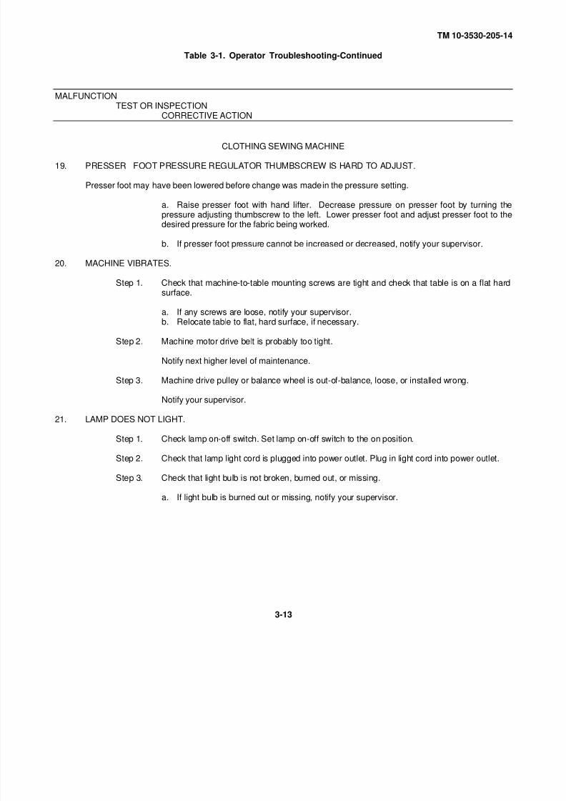
8/7/2019 TM 10-3530-205-10 CLOTHING REPAIR SHOP
http://slidepdf.com/reader/full/tm-10-3530-205-10-clothing-repair-shop 145/455
TM 10-3530-205-14
Table 3-1. Operator Troubleshooting-Continued
MALFUNCTIONTEST OR INSPECTION
CORRECTIVE ACTION
CLOTHING SEWING MACHINE
19. PRESSER FOOT PRESSURE REGULATOR THUMBSCREW IS HARD TO ADJUST.
Presser foot may have been lowered before change was made in the pressure setting.
a. Raise presser foot with hand lifter. Decrease pressure on presser foot by turning thepressure adjusting thumbscrew to the left. Lower presser foot and adjust presser foot to thedesired pressure for the fabric being worked.
b. If presser foot pressure cannot be increased or decreased, notify your supervisor.
20. MACHINE VIBRATES.
Step 1. Check that machine-to-table mounting screws are tight and check that table is on a flat hardsurface.
a. If any screws are loose, notify your supervisor.b. Relocate table to flat, hard surface, if necessary.
Step 2. Machine motor drive belt is probably too tight.
Notify next higher level of maintenance.
Step 3. Machine drive pulley or balance wheel is out-of-balance, loose, or installed wrong.
Notify your supervisor.
21. LAMP DOES NOT LIGHT.
Step 1. Check lamp on-off switch. Set lamp on-off switch to the on position.
Step 2. Check that lamp light cord is plugged into power outlet. Plug in light cord into power outlet.
Step 3. Check that light bulb is not broken, burned out, or missing.
a. If light bulb is burned out or missing, notify your supervisor.
3-13
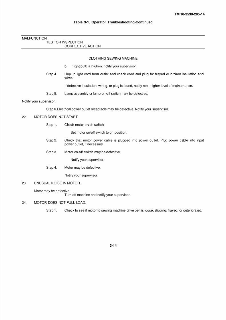
8/7/2019 TM 10-3530-205-10 CLOTHING REPAIR SHOP
http://slidepdf.com/reader/full/tm-10-3530-205-10-clothing-repair-shop 146/455
TM 10-3530-205-14
Table 3-1. Operator Troubleshooting-Continued
MALFUNCTIONTEST OR INSPECTION
CORRECTIVE ACTION
CLOTHING SEWING MACHINE
b. If light bulb is broken, notify your supervisor.
Step 4. Unplug light cord from outlet and check cord and plug for frayed or broken insulation andwires.
If defective insulation, wiring, or plug is found, notify next higher level of maintenance.
Step 5. Lamp assembly or lamp on-off switch may be defective.
Notify your supervisor.
Step 6.Electrical power outlet receptacle may be defective. Notify your supervisor.
22. MOTOR DOES NOT START.
Step 1. Check motor on/off switch.
Set motor on/off switch to on position.
Step 2. Check that motor power cable is plugged into power outlet. Plug power cable into inputpower outlet, if necessary.
Step 3. Motor on-off switch may be defective.
Notify your supervisor.
Step 4. Motor may be defective.
Notify your supervisor.
23. UNUSUAL NOISE IN MOTOR.
Motor may be defective.Turn off machine and notify your supervisor.
24. MOTOR DOES NOT PULL LOAD.
Step 1. Check to see if motor to sewing machine drive belt is loose, slipping, frayed, or deteriorated.
3-14
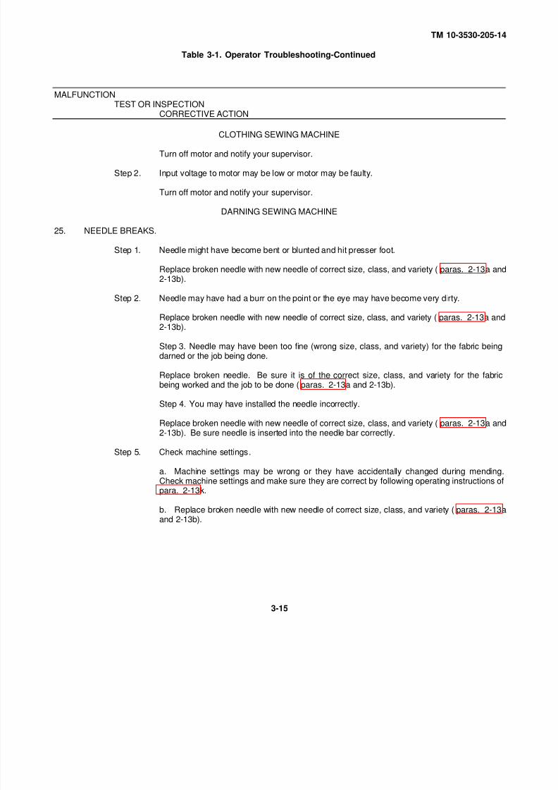
8/7/2019 TM 10-3530-205-10 CLOTHING REPAIR SHOP
http://slidepdf.com/reader/full/tm-10-3530-205-10-clothing-repair-shop 147/455
TM 10-3530-205-14
Table 3-1. Operator Troubleshooting-Continued
MALFUNCTIONTEST OR INSPECTION
CORRECTIVE ACTION
CLOTHING SEWING MACHINE
Turn off motor and notify your supervisor.
Step 2. Input voltage to motor may be low or motor may be faulty.
Turn off motor and notify your supervisor.
DARNING SEWING MACHINE
25. NEEDLE BREAKS.
Step 1. Needle might have become bent or blunted and hit presser foot.
Replace broken needle with new needle of correct size, class, and variety ( paras. 2-13 a and2-13b).
Step 2. Needle may have had a burr on the point or the eye may have become very dirty.
Replace broken needle with new needle of correct size, class, and variety ( paras. 2-13 a and2-13b).
Step 3. Needle may have been too fine (wrong size, class, and variety) for the fabric beingdarned or the job being done.
Replace broken needle. Be sure it is of the correct size, class, and variety for the fabricbeing worked and the job to be done ( paras. 2-13 a and 2-13b).
Step 4. You may have installed the needle incorrectly.
Replace broken needle with new needle of correct size, class, and variety ( paras. 2-13 a and2-13b). Be sure needle is inserted into the needle bar correctly.
Step 5. Check machine settings.
a. Machine settings may be wrong or they have accidentally changed during mending.Check machine settings and make sure they are correct by following operating instructions ofpara. 2-13 k.
b. Replace broken needle with new needle of correct size, class, and variety ( paras. 2-13 aand 2-13b).
3-15
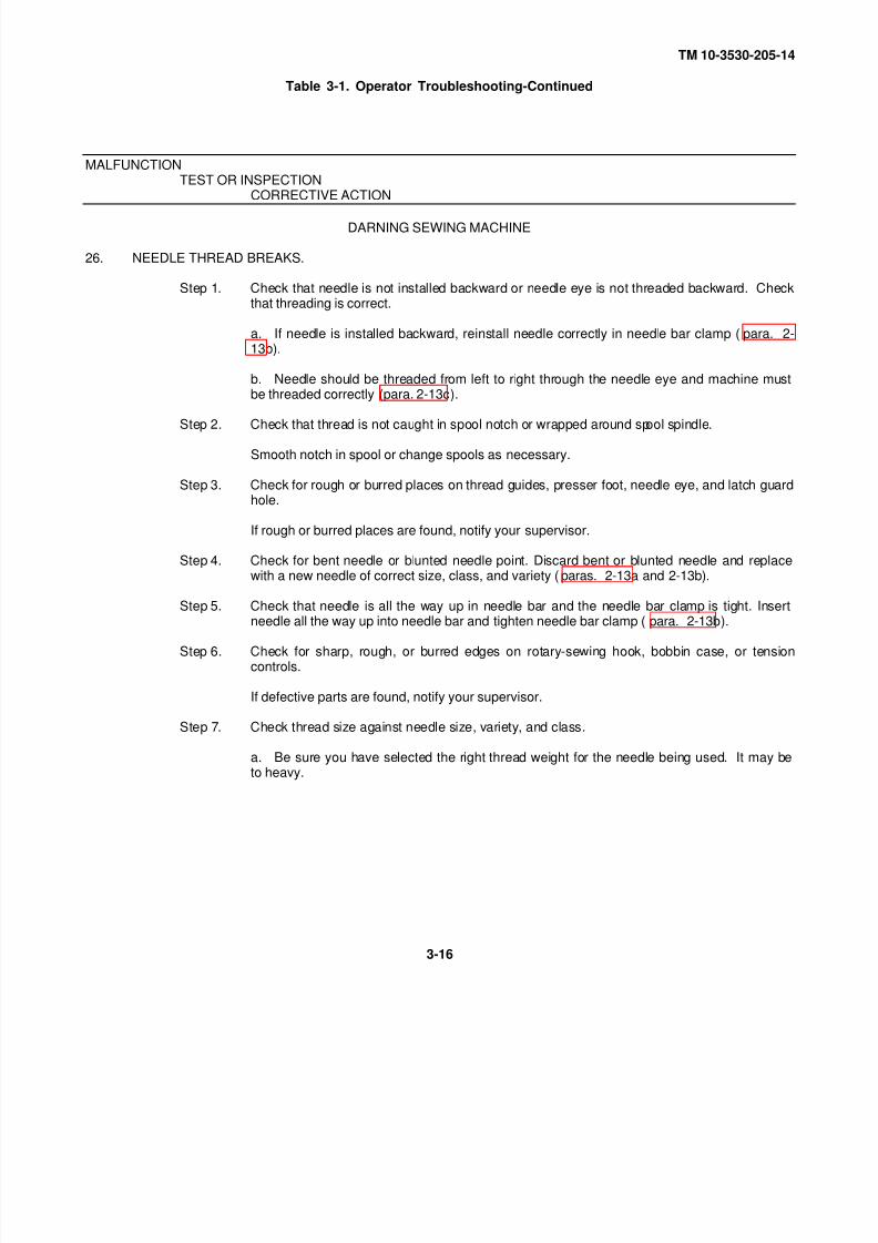
8/7/2019 TM 10-3530-205-10 CLOTHING REPAIR SHOP
http://slidepdf.com/reader/full/tm-10-3530-205-10-clothing-repair-shop 148/455
TM 10-3530-205-14
Table 3-1. Operator Troubleshooting-Continued
MALFUNCTIONTEST OR INSPECTION
CORRECTIVE ACTION
DARNING SEWING MACHINE
26. NEEDLE THREAD BREAKS.
Step 1. Check that needle is not installed backward or needle eye is not threaded backward. Checkthat threading is correct.
a. If needle is installed backward, reinstall needle correctly in needle bar clamp ( para. 2-13 b).
b. Needle should be threaded from left to right through the needle eye and machine must
be threaded correctly (para. 2-13c ).Step 2. Check that thread is not caught in spool notch or wrapped around spool spindle.
Smooth notch in spool or change spools as necessary.
Step 3. Check for rough or burred places on thread guides, presser foot, needle eye, and latch guardhole.
If rough or burred places are found, notify your supervisor.
Step 4. Check for bent needle or blunted needle point. Discard bent or blunted needle and replacewith a new needle of correct size, class, and variety ( paras. 2-13a and 2-13b).
Step 5. Check that needle is all the way up in needle bar and the needle bar clamp is tight. Insertneedle all the way up into needle bar and tighten needle bar clamp ( para. 2-13b ).
Step 6. Check for sharp, rough, or burred edges on rotary-sewing hook, bobbin case, or tensioncontrols.
If defective parts are found, notify your supervisor.
Step 7. Check thread size against needle size, variety, and class.
a. Be sure you have selected the right thread weight for the needle being used. It may beto heavy.
3-16
8/7/2019 TM 10-3530-205-10 CLOTHING REPAIR SHOP
http://slidepdf.com/reader/full/tm-10-3530-205-10-clothing-repair-shop 149/455
8/7/2019 TM 10-3530-205-10 CLOTHING REPAIR SHOP
http://slidepdf.com/reader/full/tm-10-3530-205-10-clothing-repair-shop 150/455
TM 10-3530-205-14
Table 3-1. Operator Troubleshooting-Continued
MALFUNCTIONTEST OR INSPECTION
CORRECTIVE ACTION
Step 6. Check for rough, sharp, or burred edges on rotary-sewing hook, bobbin, and bobbin case.
If defects are found, notify your supervisor.
Step 7. Check that thread being used is not damp, old, or dried out.
Discard damp, old, or dried out thread. Rewind bobbin with fresh, dry, smooth thread of thecorrect weight (paras. 2-13 d through 2-13h).
28. STITCHES SKIP OR FAIL TO LOCK.
NOTE
The most common cause of fail-to-lock or skipped stitches, is using the wrong needle for the fabric being mended. Always use the correct size, class, and variety needle recommended for the fabric being worked.
Step 1. Check that needle size, class, and variety is right for the fabric in work.
If needle is incorrect, replace needle with new needle of correct size, class, and variety(paras. 2-13 a and 2-13b).
Step 2. There may not be enough pressure on the presser foot for the fabric being worked.
Vary pressure of presser foot using pressure regulator to try and correct trouble.
Step 3. Check that needle is not blunted or bent.
If blunted or bent, replace needle with a new needle of correct size, class, and variety ( paras.2-13 a and 2-13b).
NOTE
Even if you see nothing wrong with the needle, it may have accumulated lint or sizing from the fabric. This can happen with certain synthetics and permanent press fabrics or in stitching through adhesives. Clean the needle or change it if this problem is suspected.
3-18
8/7/2019 TM 10-3530-205-10 CLOTHING REPAIR SHOP
http://slidepdf.com/reader/full/tm-10-3530-205-10-clothing-repair-shop 151/455
TM 10-3530-205-14
Table 3-1. Operator Troubleshooting-Continued
MALFUNCTIONTEST OR INSPECTION
CORRECTIVE ACTION
DARNING SEWING MACHINE
Step 4. Needle bar is out of adjustment.
Notify your supervisor.
29. SEAMS DRAW.
Needle thread or bobbin thread tension too tight.
Adjust needle thread and bobbin thread to correct tension ( para. 2-13 k).
30. THREAD SNARLS AT BEGINNING OF DARN.
NOTESnarls at the start of a mend can usually be prevented by manually placing needle into fabric before lowering pressure foot. Be sure you have both needle and bobbin threads under the presser foot and drawn to the rear. Hold both thread ends for the first few stitches.
Thread and/or fabric are probably pulled down into the bobbin area.
a. To release snarl, turn handwheel back and forth a few times to loosen the caughtmaterial. Remove the material and snarled thread and observe the note above beforeresuming work.
b. Check that machine is threaded correctly. Rethread machine if necessary ( para. 2-13c )
31. THREAD SNARLS DURING DARNING,
Step 1. Lint from the bobbin area may be caught in the stitching.
Clean bobbin area of lint.
Step 2. Bobbin thread may be running out.
Replace with a fully wound bobbin ( paras. 2-13 d through 2-13h).
Step 3. Needle thread or bobbin thread tensions may be incorrect.
3-19
8/7/2019 TM 10-3530-205-10 CLOTHING REPAIR SHOP
http://slidepdf.com/reader/full/tm-10-3530-205-10-clothing-repair-shop 152/455
TM 10-3530-205-14
Table 3-1. Operator Troubleshooting-Continued
MALFUNCTIONTEST OR INSPECTION
CORRECTIVE ACTION
DARNING SEWING MACHINE
Adjust needle thread and bobbin thread to correct tension ( para. 2-13 k).
Step 4. Machine timing may be off. Notify your supervisor.
32. THREAD SNARLS AT END OF DARN.
NOTE
As a general rule, it is not a good practice to mend off the fabric. This can cause thread knotting in the bobbin area and snarls at the end of the mend.
Step 1. Fabric and thread are being pushed into the bobbin area causing knots.
Turn the handwheel back and forth a few times to loosen snarl; then remove snarl.
Step 2. Check all machine adjustments and readjust as necessary.
If trouble still persists, notify your supervisor.
33. BOBBIN THREAD CANNOT BE RAISED THROUGH HIOLE IN LATCH PLATE.
Step 1. Check bobbin case threading.
Rethread bobbin case (para. 2-13 f).
Step 2. Check that bobbin case is seated in rotary-sewing hook correctly.
Seat bobbin case correctly ( para. 2-13g ).
34. PRESSER FOOT PRESSURE REGULATOR THUMBSCREW IS HARD TO ADJUST.
Presser foot may have been lowered before change was made in the pressure setting.
3-20
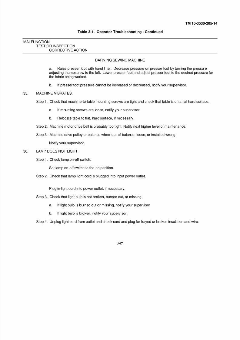
8/7/2019 TM 10-3530-205-10 CLOTHING REPAIR SHOP
http://slidepdf.com/reader/full/tm-10-3530-205-10-clothing-repair-shop 153/455
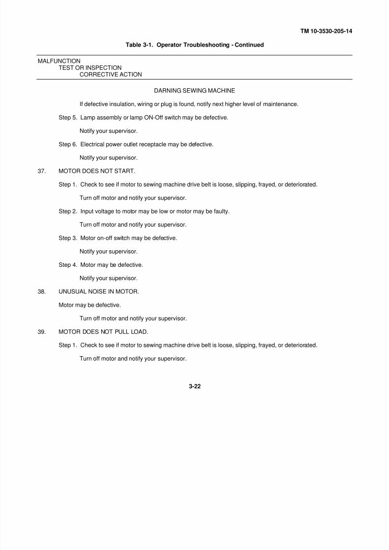
8/7/2019 TM 10-3530-205-10 CLOTHING REPAIR SHOP
http://slidepdf.com/reader/full/tm-10-3530-205-10-clothing-repair-shop 154/455
TM 10-3530-205-14
Table 3-1. Operator Troubleshooting - Continued
MALFUNCTIONTEST OR INSPECTION
CORRECTIVE ACTION
DARNING SEWING MACHINE
If defective insulation, wiring or plug is found, notify next higher level of maintenance.
Step 5. Lamp assembly or lamp ON-Off switch may be defective.
Notify your supervisor.
Step 6. Electrical power outlet receptacle may be defective.
Notify your supervisor.
37. MOTOR DOES NOT START.
Step 1. Check to see if motor to sewing machine drive belt is loose, slipping, frayed, or deteriorated.
Turn off motor and notify your supervisor.
Step 2. Input voltage to motor may be low or motor may be faulty.
Turn off motor and notify your supervisor.
Step 3. Motor on-off switch may be defective.
Notify your supervisor.
Step 4. Motor may be defective.
Notify your supervisor.
38. UNUSUAL NOISE IN MOTOR.
Motor may be defective.
Turn off motor and notify your supervisor.
39. MOTOR DOES NOT PULL LOAD.
Step 1. Check to see if motor to sewing machine drive belt is loose, slipping, frayed, or deteriorated.
Turn off motor and notify your supervisor.
3-22
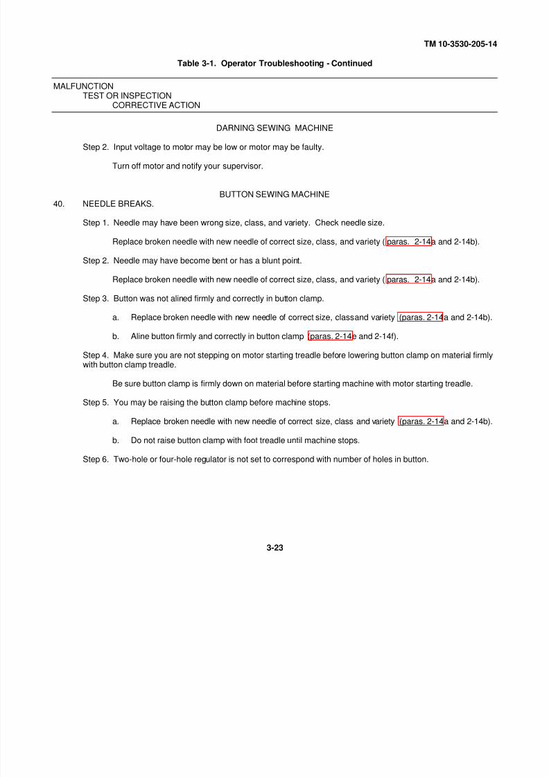
8/7/2019 TM 10-3530-205-10 CLOTHING REPAIR SHOP
http://slidepdf.com/reader/full/tm-10-3530-205-10-clothing-repair-shop 155/455
TM 10-3530-205-14
Table 3-1. Operator Troubleshooting - Continued
MALFUNCTIONTEST OR INSPECTION
CORRECTIVE ACTION
DARNING SEWING MACHINE
Step 2. Input voltage to motor may be low or motor may be faulty.
Turn off motor and notify your supervisor.
BUTTON SEWING MACHINE40. NEEDLE BREAKS.
Step 1. Needle may have been wrong size, class, and variety. Check needle size.
Replace broken needle with new needle of correct size, class, and variety ( paras. 2-14 a and 2-14b).
Step 2. Needle may have become bent or has a blunt point.
Replace broken needle with new needle of correct size, class, and variety ( paras. 2-14 a and 2-14b).
Step 3. Button was not alined firmly and correctly in button clamp.
a. Replace broken needle with new needle of correct size, class and variety (paras. 2-14 a and 2-14b).
b. Aline button firmly and correctly in button clamp (paras. 2-14 e and 2-14f).
Step 4. Make sure you are not stepping on motor starting treadle before lowering button clamp on material firmlywith button clamp treadle.
Be sure button clamp is firmly down on material before starting machine with motor starting treadle.
Step 5. You may be raising the button clamp before machine stops.
a. Replace broken needle with new needle of correct size, class and variety (paras. 2-14 a and 2-14b).
b. Do not raise button clamp with foot treadle until machine stops.
Step 6. Two-hole or four-hole regulator is not set to correspond with number of holes in button.
3-23
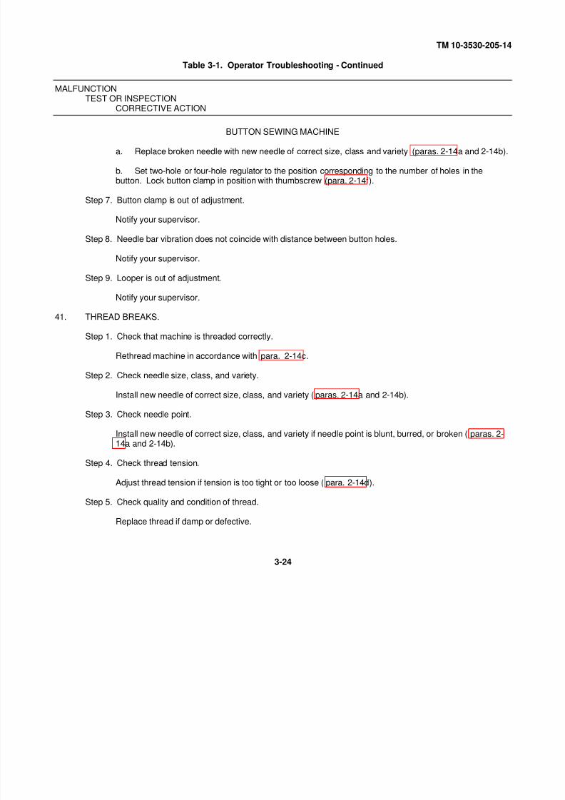
8/7/2019 TM 10-3530-205-10 CLOTHING REPAIR SHOP
http://slidepdf.com/reader/full/tm-10-3530-205-10-clothing-repair-shop 156/455
TM 10-3530-205-14
Table 3-1. Operator Troubleshooting - Continued
MALFUNCTIONTEST OR INSPECTION
CORRECTIVE ACTION
BUTTON SEWING MACHINE
a. Replace broken needle with new needle of correct size, class and variety (paras. 2-14 a and 2-14b).
b. Set two-hole or four-hole regulator to the position corresponding to the number of holes in thebutton. Lock button clamp in position with thumbscrew (para. 2-14f ).
Step 7. Button clamp is out of adjustment.
Notify your supervisor.
Step 8. Needle bar vibration does not coincide with distance between button holes.
Notify your supervisor.
Step 9. Looper is out of adjustment.
Notify your supervisor.
41. THREAD BREAKS.
Step 1. Check that machine is threaded correctly.
Rethread machine in accordance with para. 2-14c .
Step 2. Check needle size, class, and variety.
Install new needle of correct size, class, and variety ( paras. 2-14a and 2-14b).
Step 3. Check needle point.
Install new needle of correct size, class, and variety if needle point is blunt, burred, or broken ( paras. 2-14 a and 2-14b).
Step 4. Check thread tension.
Adjust thread tension if tension is too tight or too loose ( para. 2-14d ).
Step 5. Check quality and condition of thread.
Replace thread if damp or defective.
3-24
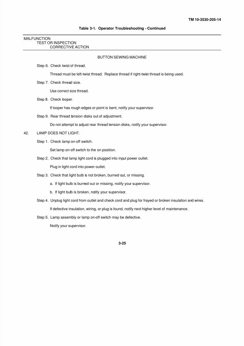
8/7/2019 TM 10-3530-205-10 CLOTHING REPAIR SHOP
http://slidepdf.com/reader/full/tm-10-3530-205-10-clothing-repair-shop 157/455
TM 10-3530-205-14
Table 3-1. Operator Troubleshooting - Continued
MALFUNCTIONTEST OR INSPECTION
CORRECTIVE ACTION
BUTTON SEWING MACHINE
Step 6. Check twist of thread.
Thread must be left-twist thread. Replace thread if right-twist thread is being used.
Step 7. Check thread size.
Use correct size thread.
Step 8. Check looper.
If looper has rough edges or point is bent, notify your supervisor.
Step 9. Rear thread tension disks out of adjustment.
Do not attempt to adjust rear thread tension disks, notify your supervisor.
42. LAMP DOES NOT LIGHT.
Step 1. Check lamp on-off switch.
Set lamp on-off switch to the on position.
Step 2. Check that lamp light cord is plugged into input power outlet.
Plug in light cord into power outlet.
Step 3. Check that light bulb is not broken, burned out, or missing.
a. If light bulb is burned out or missing, notify your supervisor.
b. If light bulb is broken, notify your supervisor.
Step 4. Unplug light cord from outlet and check cord and plug for frayed or broken insulation and wires.
If defective insulation, wiring, or plug is found, notify next higher level of maintenance.
Step 5. Lamp assembly or lamp on-off switch may be defective.
Notify your supervisor.
3-25
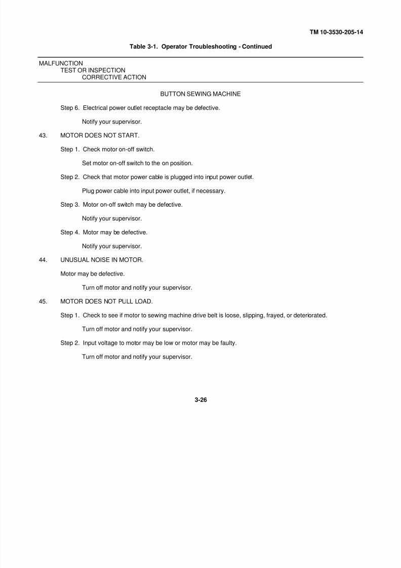
8/7/2019 TM 10-3530-205-10 CLOTHING REPAIR SHOP
http://slidepdf.com/reader/full/tm-10-3530-205-10-clothing-repair-shop 158/455
TM 10-3530-205-14
Table 3-1. Operator Troubleshooting - Continued
MALFUNCTIONTEST OR INSPECTION
CORRECTIVE ACTION
BUTTON SEWING MACHINE
Step 6. Electrical power outlet receptacle may be defective.
Notify your supervisor.
43. MOTOR DOES NOT START.
Step 1. Check motor on-off switch.
Set motor on-off switch to the on position.
Step 2. Check that motor power cable is plugged into input power outlet.
Plug power cable into input power outlet, if necessary.
Step 3. Motor on-off switch may be defective.
Notify your supervisor.
Step 4. Motor may be defective.
Notify your supervisor.
44. UNUSUAL NOISE IN MOTOR.
Motor may be defective.
Turn off motor and notify your supervisor.
45. MOTOR DOES NOT PULL LOAD.
Step 1. Check to see if motor to sewing machine drive belt is loose, slipping, frayed, or deteriorated.
Turn off motor and notify your supervisor.
Step 2. Input voltage to motor may be low or motor may be faulty.
Turn off motor and notify your supervisor.
3-26
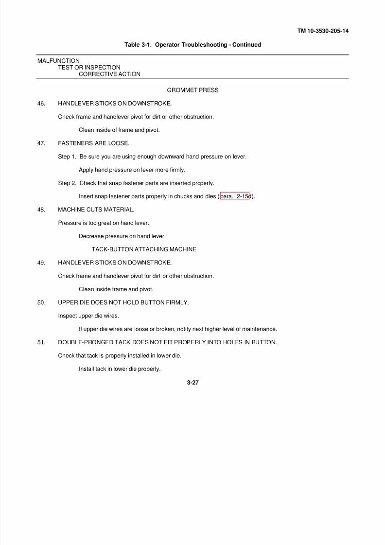
8/7/2019 TM 10-3530-205-10 CLOTHING REPAIR SHOP
http://slidepdf.com/reader/full/tm-10-3530-205-10-clothing-repair-shop 159/455
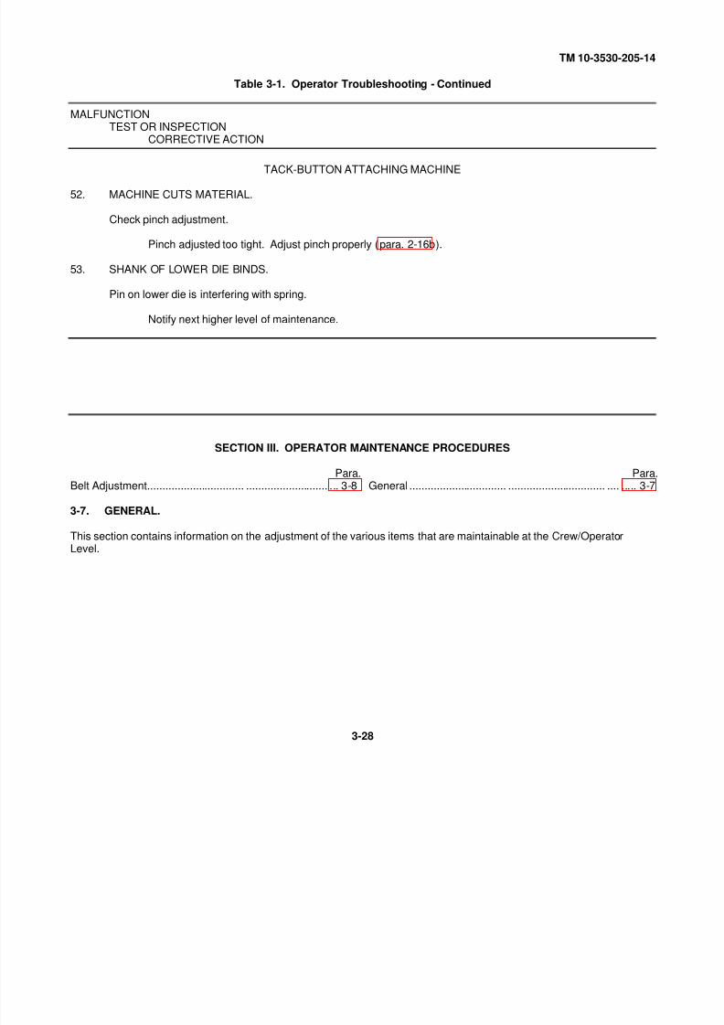
8/7/2019 TM 10-3530-205-10 CLOTHING REPAIR SHOP
http://slidepdf.com/reader/full/tm-10-3530-205-10-clothing-repair-shop 160/455
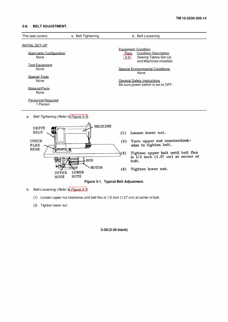
8/7/2019 TM 10-3530-205-10 CLOTHING REPAIR SHOP
http://slidepdf.com/reader/full/tm-10-3530-205-10-clothing-repair-shop 161/455
TM 10-3530-205-14
3-8. BELT ADJUSTMENT.
This task covers: a. Belt Tightening b. Belt Loosening
INITIAL SET-UPEquipment Condition
Applicable Configuration Para. Condition DescriptionNone 2-9 Sewing Tables Set-Up
and Machines Installed.Test Equipment
None Special Environmental ConditionsNone
Special ToolsNone General Safety Instructions
Be sure power switch is set to OFF.Material/Parts
None
Personnel Required1 Person
a. Belt Tightening (Refer to Figure 3-1) .
Figure 3-1. Typical Belt Adjustment.
b. Belt Loosening (Refer to Figure 3-1) .
(1) Loosen upper nut clockwise until belt flex is 1/2 inch (1.27 cm) at center of belt.
(2) Tighten lower nut.
3-29/(3-30 blank)

8/7/2019 TM 10-3530-205-10 CLOTHING REPAIR SHOP
http://slidepdf.com/reader/full/tm-10-3530-205-10-clothing-repair-shop 162/455
8/7/2019 TM 10-3530-205-10 CLOTHING REPAIR SHOP
http://slidepdf.com/reader/full/tm-10-3530-205-10-clothing-repair-shop 163/455
TM 10-3530-205-14
CHAPTER 4
MAINTENANCE OF AUXILIARY EQUIPMENT
Para. Para.
General................................ ................................ ..... .....4-1 Fire Extinguisher ................................ ....................... .... 4-2
4- 1. GENERAL.
This chapter contains the necessary instructions, descriptions, and references for operating the auxiliary materiel orcomponents used in conjunction with the clothing repair shop. The auxiliary components include a fire extinguisher anda generator set.The necessary instructions for the operation and the maintenance of the fire extinguisher is given inparagraph 4-2. Refer to the TM 5-6115-271-14 for the operation and maintenance of the generator set and to TM 9-2330-213-14 for operation and maintenance of the cargo trailer.
4-2. FIRE EXTINGUISHER.
A 5-pound carbon dioxide (CO 2) fire extinguisher is issued with the clothing repair shop.
a. Operation. Operate the fire extinguisher by following the procedures in the order in which they are listed below.
1. Carry the fire extinguisher by the handle to the fire.
2. Pull out the safety pin, breaking the wire seal, and swing the horn toward the base of the fire.
WARNING
Do not let eyes, hands, or body come directly in contact with the fog, as frostbite or freezing may result.
3. Depress the operating lever to open the valve, and direct the discharge or fog toward the base of the fire.
b. Maintenance. Inspect the fire extinguisher for broken wire seal. Recharge the fire extinguisher immediately afterit has been used or if the loss of gas exceeds one-half of a pound. The weight of the fire extinguisher is stamped on thevalve.
4-1/ 4-2 Blank

8/7/2019 TM 10-3530-205-10 CLOTHING REPAIR SHOP
http://slidepdf.com/reader/full/tm-10-3530-205-10-clothing-repair-shop 164/455
8/7/2019 TM 10-3530-205-10 CLOTHING REPAIR SHOP
http://slidepdf.com/reader/full/tm-10-3530-205-10-clothing-repair-shop 165/455
8/7/2019 TM 10-3530-205-10 CLOTHING REPAIR SHOP
http://slidepdf.com/reader/full/tm-10-3530-205-10-clothing-repair-shop 166/455
TM 10-3530-205-14
SECTION II. SERVICE UPON RECEIPT
Para. Para.Service Upon Receipt of a
Complete ClothingRepair Shop................................ ........................ ..... 5-5
Service Upon Receipt ofNew or ReplacementEquipment ................................ ......................... .... 5-4
5-4. SERVICE UPON RECEIPT OF NEW OR REPLACEMENT EQUIPMENT.
When new or replacement items of equipment are received by the using organization, they must be unpacked andinspected before they are fielded as part of the clothing repair shop. The services performed are the responsibility oforganizational personnel as described below:
a. Unpacking New or Replacement Equipment.
Use caution when unpacking the equipment from the original shipping containers. The use of screwdrivers and prybars to open shipping containers can cause damage to equipment if not used properly. Observe all precautions noted on the shipping tag.
(1) Remove and discard all tape and materials used in packing the equipment.
(2) Remove and discard any dissecant packages that may have been used in the packaging.
(3) Remove any preservative compounds that may have been sprayed on metal surfaces prior to packaging.Because these compounds are not lubricants, take special care to remove them from all wearing surfaces.
b. Checking Unpacked New Equipment or Replacement Equipment. Check unpacked items of equipment asfollows:
(1) Inspect the equipment for damage incurred during shipment. If the equipment has been damaged, report thedamage on DD Form 6, Packaging Improvement Report.
(2) Check the equipment against the packing slip to see if the shipment is complete. Report all discrepancies inaccordance with the instructions contained in DA PAM 738-750.
5-2
8/7/2019 TM 10-3530-205-10 CLOTHING REPAIR SHOP
http://slidepdf.com/reader/full/tm-10-3530-205-10-clothing-repair-shop 167/455
TM 10-3530-205-14
5-4. SERVICE UPON RECEIPT OF NEW OR REPLACEMENT EQUIPMENT - Continued.
b. Checking Unpacked New Equipment or Replacement Equipment - Continued.
(3) Check to see whether the equipment has been modified. If equipment has been modified, check equipmentdecals to insure that the Modification Work Order has been completed and dated.
5-5. SERVICE UPON RECEIPT OF COMPLETE CLOTHING REPAIR SHOP.
When either a new or used clothing repair shop is received by an organization, the organizational personnel must inspectand service each component to prepare it for operation. The operator will assist the organizational personnel when he isdirected to do so.
a. Unpacking and Unloading of Equipment From Cabinet Assembly.
Use caution when unpacking the equipment from the original shipping containers. The use of screwdrivers and prybars to open shipping containers can cause damage to equipment if not used properly. Observe all precautions noted on the shipping tag.
(1) Remove the equipment from the cabinet assembly and set it up in accordance with the instructions containedin Chapter 2, Section I of this manual.
(2) Remove and discard all protective tape and packing material.
(3) As the cabinet assembly is unloaded, check the equipment against the Components of End Item List(COEIL), contained in Appendix C of this manual to ensure that all items of the clothing repair shop areaccounted for.
b. Inspection and Servicing of Unpacked Equipment.
(1) Carry out a complete visual inspection of the clothing repair shop equipment, taking special notice of anydamaged or missing parts which might have been sustained in transit. Read any warnings on the shippingtag to determine the condition in which the clothing repair shop was shipped. Observe all precautions notedon the shipping tag.
(2) Perform the quarterly preventive maintenance checks and services (PMCS) described in Section III of thischapter.
5-3
8/7/2019 TM 10-3530-205-10 CLOTHING REPAIR SHOP
http://slidepdf.com/reader/full/tm-10-3530-205-10-clothing-repair-shop 168/455
TM 10-3530-205-14
5-5. SERVICE UPON RECEIPT OF COMPLETE CLOTHING EQUIPMENT - Continued.
b. Inspection and Servicing of Unpacked Equipment - Continued.
(3) Perform the lubrication services contained i n Chapter 3 , Section I of this manual.
(4) Perform PMCS and lubrication services for the generator set as described in TM 5-6115-271-14.(5) Perform the PMCS and lubrication services for the cargo trailer as described in TM 9-2330-213-14.
NOTE
The services performed at this time will begin the cycle of regularly scheduled quarterly preventive maintenance services.
SECTION III. ORGANIZATIONAL PREVENTIVE MAINTENANCE CHECKS AND SERVICES (PMCS)
5-6. GENERAL.
a. To obtain long life and best performance from the equipment of the clothing repair shop, you must adhere to thepreventive maintenance checks and services contained in this section. The required PMCS to be performed quarterly byorganizational maintenance personnel is listed and described in Tables 5-1 through 5-6.
5-7. O RGANIZATIONAL PMCS PROCEDURES.
a. The item numbers of the tables indicate the sequence of the PMCS.
b. If something doesn't work, troubleshoot it with the instructions in this manual or notify your supervisor.
c. Always do your preventive maintenance in the same order, so it gets to be a habit. Once you've had somepractice, you'll spot anything wrong in a hurry.
d. f anything looks wrong and you can't fix it, write it down on your DA Form 2404. If you find something seriouslywrong, report it to direct support as soon as possible.
e. When you do your preventive maintenance, take along the tools and equipment, you'll need to make all thechecks. You always need a rag or two.
5-4
8/7/2019 TM 10-3530-205-10 CLOTHING REPAIR SHOP
http://slidepdf.com/reader/full/tm-10-3530-205-10-clothing-repair-shop 169/455
TM 10-3530-205-14
5-7. ORGANIZATIONAL PMCS PROCEDURES - Continued.
WARNING
Cleaning solvent, Federal Specification P-D-680, is both toxic and flammable. Keep off skin. Use only in a well-ventilated area and avoid prolonged breathing of vapors. Keep away from open
flame.
(1) Keep it clean: Dirt, grease, oil, and debris may cover up a serious problem. Clean as you work and asneeded. Use cleaning solvent (Federal Specification P-D-680) to clean metal surfaces. Use soap and waterwhen you clean cloth, rubber, painted surfaces, or plastic material.
(2) Bolts, nuts, and screws: Check that they are not loose, missing, bent, or broken. Look for chipped paint, baremetal, or rust around bolt heads. Tighten any that you find loose.
(3) Welds: Look for cracked or broken welds and cracks in parent metal. If you find a bad weld, report it to directsupport.
(4) Electric wires and connections: Look for cracked or broken insulation, bare wires, and loose or broken
connectors. Tighten loose connections and report defective wiring to Direct Support Maintenance.f. Item Number Column. This column not only indicates the sequence of performing the PMCS, but is also used as
a source of item numbers for the TM Number Column on DA Form 2404, Equipment Inspection and MaintenanceWorksheet, in recording results.
g. Item to be Inspected Column. This column identifies the item to be inspected by its common name.
h. Procedure Column. This column contains the procedures and methods required to perform the PMCS.
5-5
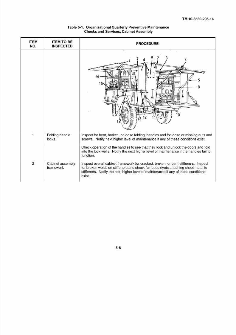
8/7/2019 TM 10-3530-205-10 CLOTHING REPAIR SHOP
http://slidepdf.com/reader/full/tm-10-3530-205-10-clothing-repair-shop 170/455
TM 10-3530-205-14
Table 5-1. Organizational Quarterly Preventive MaintenanceChecks and Services, Cabinet Assembly
ITEMNO.
ITEM TO BEINSPECTED
PROCEDURE
1 Folding handlelocks
Inspect for bent, broken, or loose folding handles and for loose or missing nuts andscrews. Notify next higher level of maintenance if any of these conditions exist.
Check operation of the handles to see that they lock and unlock the doors and foldinto the lock wells. Notify the next higher level of maintenance if the handles fail tofunction.
2 Cabinet assemblyframework
Inspect overall cabinet framework for cracked, broken, or bent stiffeners. Inspectfor broken welds on stiffeners and check for loose rivets attaching sheet metal tostiffeners. Notify the next higher level of maintenance if any of these conditionsexist.
5-6
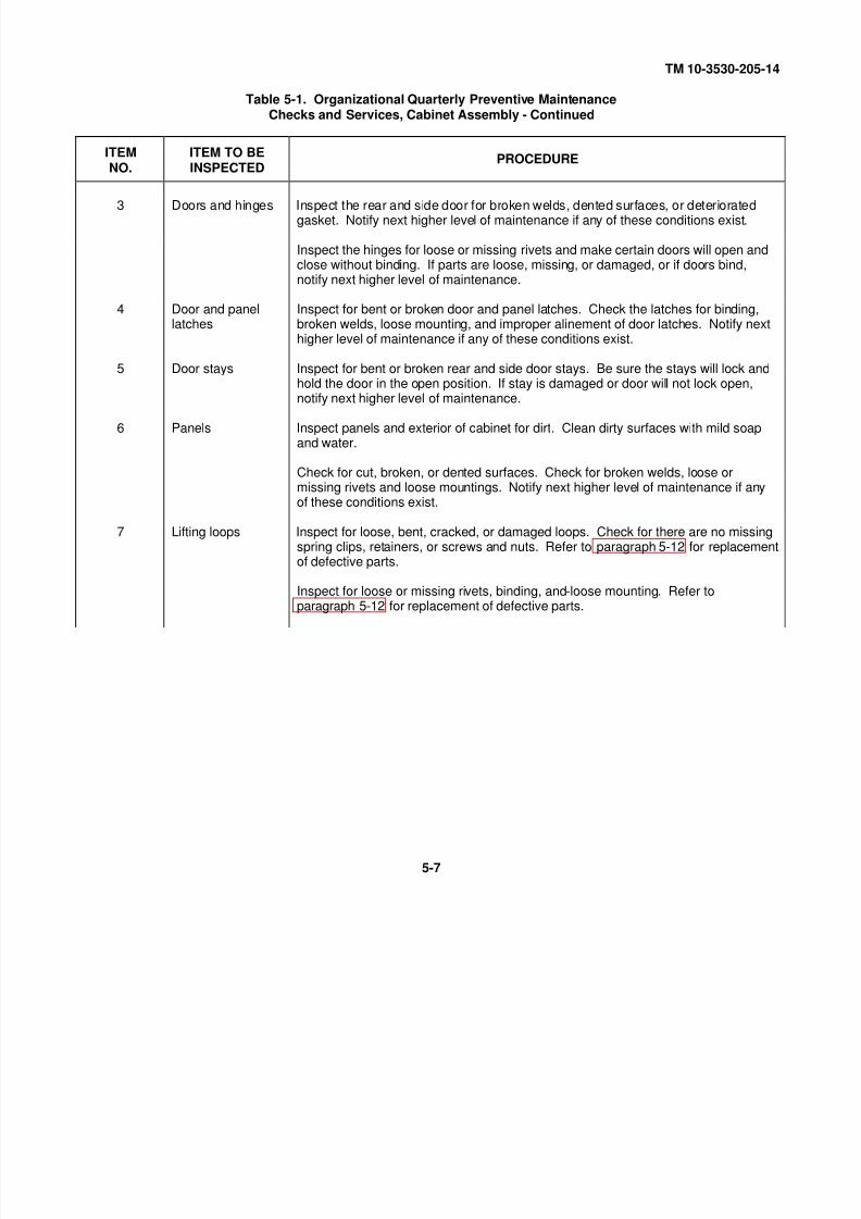
8/7/2019 TM 10-3530-205-10 CLOTHING REPAIR SHOP
http://slidepdf.com/reader/full/tm-10-3530-205-10-clothing-repair-shop 171/455
TM 10-3530-205-14
Table 5-1. Organizational Quarterly Preventive MaintenanceChecks and Services, Cabinet Assembly - Continued
ITEMNO.
ITEM TO BEINSPECTED
PROCEDURE
3 Doors and hinges Inspect the rear and side door for broken welds, dented surfaces, or deterioratedgasket. Notify next higher level of maintenance if any of these conditions exist.
Inspect the hinges for loose or missing rivets and make certain doors will open andclose without binding. If parts are loose, missing, or damaged, or if doors bind,notify next higher level of maintenance.
4 Door and panellatches
Inspect for bent or broken door and panel latches. Check the latches for binding,broken welds, loose mounting, and improper alinement of door latches. Notify nexthigher level of maintenance if any of these conditions exist.
5 Door stays Inspect for bent or broken rear and side door stays. Be sure the stays will lock andhold the door in the open position. If stay is damaged or door will not lock open,notify next higher level of maintenance.
6 Panels Inspect panels and exterior of cabinet for dirt. Clean dirty surfaces with mild soapand water.
Check for cut, broken, or dented surfaces. Check for broken welds, loose ormissing rivets and loose mountings. Notify next higher level of maintenance if anyof these conditions exist.
7 Lifting loops Inspect for loose, bent, cracked, or damaged loops. Check for there are no missingspring clips, retainers, or screws and nuts. Refer to paragraph 5-12 for replacementof defective parts.
Inspect for loose or missing rivets, binding, and-loose mounting. Refer toparagraph 5-12 for replacement of defective parts.
5-7
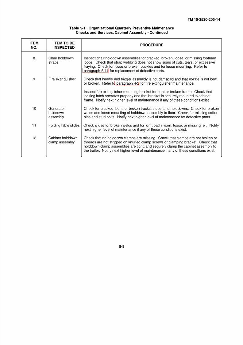
8/7/2019 TM 10-3530-205-10 CLOTHING REPAIR SHOP
http://slidepdf.com/reader/full/tm-10-3530-205-10-clothing-repair-shop 172/455
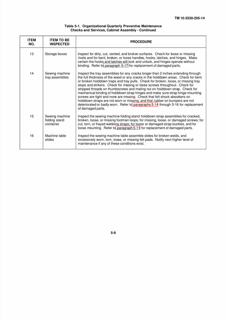
8/7/2019 TM 10-3530-205-10 CLOTHING REPAIR SHOP
http://slidepdf.com/reader/full/tm-10-3530-205-10-clothing-repair-shop 173/455
TM 10-3530-205-14
Table 5-1. Organizational Quarterly Preventive MaintenanceChecks and Services, Cabinet Assembly - Continued
ITEMNO.
ITEM TO BEINSPECTED
PROCEDURE
13 Storage boxes Inspect for dirty, cut, dented, and broken surfaces. Check for loose or missingrivets and for bent, broken, or loose handles, hooks, latches, and hinges. Makecertain the hooks and latches will lock and unlock, and hinges operate withoutbinding. Refer to paragraph 5-17 for replacement of damaged parts.
14 Sewing machinetray assemblies
Inspect the tray assemblies for any cracks longer than 2 inches extending throughthe full thickness of the wood or any cracks in the holddown areas. Check for bentor broken holddown traps and tray pulls. Check for broken, loose, or missing traystops and strikers. Check for missing or loose screws throughout. Check forstripped threads on thumbscrews and mating nut on holddown strap. Check formechanical binding of holddown strap hinges and make sure strap hinge mountingscrews are tight and none are missing. Check that felt shock absorbers onholddown straps are not worn or missing, and that rubber on bumpers are notdeteriorated or badly worn. Refer to paragraphs 5-14 through 5-16 for replacementof damaged parts.
15 Sewing machinefolding standcontainer
Inspect the sewing machine folding stand holddown strap assemblies for cracked,broken, loose, or missing footman loops; for missing, loose, or damaged screws; forcut, torn, or frayed webbing straps; for loose or damaged strap buckles, and forloose mounting. Refer to paragraph 5-11 for replacement of damaged parts.
16 Machine tableslides
Inspect the sewing machine table assemble slides for broken welds, andexcessively worn, torn, loose, or missing felt pads. Notify next higher level ofmaintenance if any of these conditions exist.
5-9
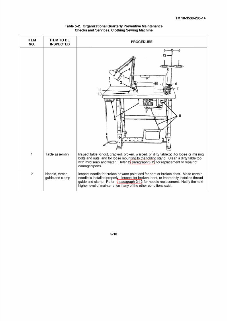
8/7/2019 TM 10-3530-205-10 CLOTHING REPAIR SHOP
http://slidepdf.com/reader/full/tm-10-3530-205-10-clothing-repair-shop 174/455
TM 10-3530-205-14
Table 5-2. Organizational Quarterly Preventive MaintenanceChecks and Services, Clothing Sewing Machine
ITEMNO.
ITEM TO BEINSPECTED
PROCEDURE
1 Table assembly Inspect table for cut, cracked, broken, warped, or dirty tabletop; for loose or missingbolts and nuts, and for loose mounting to the folding stand. Clean a dirty table topwith mild soap and water. Refer to paragraph 5-19 for replacement or repair ofdamaged parts.
2 Needle, threadguide and clamp
Inspect needle for broken or worn point and for bent or broken shaft. Make certainneedle is installed properly. Inspect for broken, bent, or improperly installed threadguide and clamp. Refer t o paragraph 2-12 for needle replacement. Notify the nexthigher level of maintenance if any of the other conditions exist.
5-10
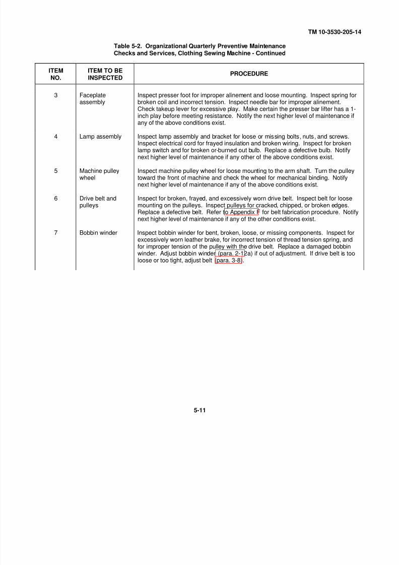
8/7/2019 TM 10-3530-205-10 CLOTHING REPAIR SHOP
http://slidepdf.com/reader/full/tm-10-3530-205-10-clothing-repair-shop 175/455
TM 10-3530-205-14
Table 5-2. Organizational Quarterly Preventive MaintenanceChecks and Services, Clothing Sewing Machine - Continued
ITEMNO.
ITEM TO BEINSPECTED
PROCEDURE
3 Faceplateassembly
Inspect presser foot for improper alinement and loose mounting. Inspect spring forbroken coil and incorrect tension. Inspect needle bar for improper alinement.Check takeup lever for excessive play. Make certain the presser bar lifter has a 1-inch play before meeting resistance. Notify the next higher level of maintenance ifany of the above conditions exist.
4 Lamp assembly Inspect lamp assembly and bracket for loose or missing bolts, nuts, and screws.Inspect electrical cord for frayed insulation and broken wiring. Inspect for brokenlamp switch and for broken or-burned out bulb. Replace a defective bulb. Notifynext higher level of maintenance if any other of the above conditions exist.
5 Machine pulleywheel
Inspect machine pulley wheel for loose mounting to the arm shaft. Turn the pulleytoward the front of machine and check the wheel for mechanical binding. Notifynext higher level of maintenance if any of the above conditions exist.
6 Drive belt andpulleys
Inspect for broken, frayed, and excessively worn drive belt. Inspect belt for loosemounting on the pulleys. Inspect pulleys for cracked, chipped, or broken edges.Replace a defective belt. Refer t o Appendix F for belt fabrication procedure. Notifynext higher level of maintenance if any of the other conditions exist.
7 Bobbin winder Inspect bobbin winder for bent, broken, loose, or missing components. Inspect forexcessively worn leather brake, for incorrect tension of thread tension spring, andfor improper tension of the pulley with the drive belt. Replace a damaged bobbinwinder. Adjust bobbin winder (para. 2-12 a) if out of adjustment. If drive belt is tooloose or too tight, adjust belt (para. 3-8) .
5-11
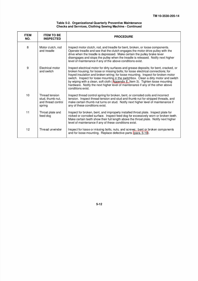
8/7/2019 TM 10-3530-205-10 CLOTHING REPAIR SHOP
http://slidepdf.com/reader/full/tm-10-3530-205-10-clothing-repair-shop 176/455
TM 10-3530-205-14
Table 5-2. Organizational Quarterly Preventive MaintenanceChecks and Services, Clothing Sewing Machine - Continued
ITEMNO.
ITEM TO BEINSPECTED
PROCEDURE
8 Motor clutch, rodand treadle
Inspect motor clutch, rod, and treadle for bent, broken, or loose components.Operate treadle and see that the clutch engages the motor drive pulley with thedrive when the treadle is depressed. Make certain the pulley brake leverdisengages and stops the pulley when the treadle is released. Notify next higherlevel of maintenance if any of the above conditions exist.
9 Electrical motorand switch
Inspect electrical motor for dirty surfaces and grease deposits; for bent, cracked, orbroken housing; for loose or missing bolts; for loose electrical connections; forfrayed insulation and broken wiring; for loose mounting. Inspect for broken motorswitch. Inspect for loose mounting in the switchbox. Clean a dirty motor and switchby wiping with a clean, soft cloth ( Appendix E, item 3). Tighten loose mountinghardware. Notify the next higher level of maintenance if any of the other aboveconditions exist.
10 Thread tensionstud, thumb nut,and thread controlspring
Inspect thread control spring for broken, bent, or corroded coils and incorrecttension. Inspect thread tension and stud and thumb nut for stripped threads, andmake certain thumb nut turns on stud. Notify next higher level of maintenance ifany of these conditions exist.
11 Throat plate andfeed dog
Inspect for broken, bent, and improperly installed throat plate. Inspect plate fornicked or corroded surface. Inspect feed dog for excessively worn or broken teeth.Make certain teeth show their full length above the throat plate. Notify next higherlevel of maintenance if any of these conditions exist.
12 Thread unwinder Inspect for loose or missing bolts, nuts, and screws; bent or broken componentsand for loose mounting. Replace defective parts (para. 5-19) .
5-12
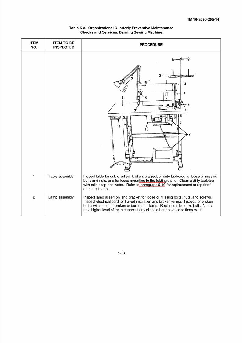
8/7/2019 TM 10-3530-205-10 CLOTHING REPAIR SHOP
http://slidepdf.com/reader/full/tm-10-3530-205-10-clothing-repair-shop 177/455
TM 10-3530-205-14
Table 5-3. Organizational Quarterly Preventive MaintenanceChecks and Services, Darning Sewing Machine
ITEMNO.
ITEM TO BEINSPECTED
PROCEDURE
1 Table assembly Inspect table for cut, cracked, broken, warped, or dirty tabletop; for loose or missingbolts and nuts, and for loose mounting to the folding stand. Clean a dirty tabletopwith mild soap and water. Refer to paragraph 5-19 for replacement or repair ofdamaged parts.
2 Lamp assembly Inspect lamp assembly and bracket for loose or missing bolts, nuts, and screws.Inspect electrical cord for frayed insulation and broken wiring. Inspect for brokenbulb switch and for broken or burned out lamp. Replace a defective bulb. Notifynext higher level of maintenance if any of the other above conditions exist.
5-13
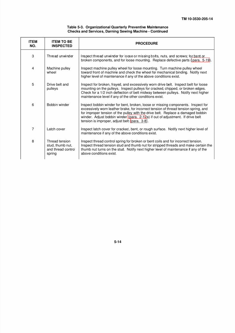
8/7/2019 TM 10-3530-205-10 CLOTHING REPAIR SHOP
http://slidepdf.com/reader/full/tm-10-3530-205-10-clothing-repair-shop 178/455
TM 10-3530-205-14
Table 5-3. Organizational Quarterly Preventive MaintenanceChecks and Services, Darning Sewing Machine - Continued
ITEMNO.
ITEM TO BEINSPECTED
PROCEDURE
3 Thread unwinder Inspect thread unwinder for loose or missing bolts, nuts, and screws; for bent orbroken components, and for loose mounting. Replace defective parts ( para. 5-19 ).
4 Machine pulleywheel
Inspect machine pulley wheel for loose mounting. Turn machine pulley wheeltoward front of machine and check the wheel for mechanical binding. Notify nexthigher level of maintenance if any of the above conditions exist.
5 Drive belt andpulleys
Inspect for broken, frayed, and excessively worn drive belt. Inspect belt for loosemounting on the pulleys. Inspect pulleys for cracked, chipped, or broken edges.Check for a 1/2 inch deflection of belt midway between pulleys. Notify next highermaintenance level if any of the other conditions exist.
6 Bobbin winder Inspect bobbin winder for bent, broken, loose or missing components. Inspect forexcessively worn leather brake, for incorrect tension of thread tension spring, andfor improper tension of the pulley with the drive belt. Replace a damaged bobbinwinder. Adjust bobbin winder (para. 2-1 2a) if out of adjustment. If drive belttension is improper, adjust belt ( para. 3-8) .
7 Latch cover Inspect latch cover for cracked, bent, or rough surface. Notify next higher level ofmaintenance if any of the above conditions exist.
8 Thread tensionstud, thumb nut,and thread controlspring
Inspect thread control spring for broken or bent coils and for incorrect tension.Inspect thread tension stud and thumb nut for stripped threads and make certain thethumb nut turns on the stud. Notify next higher level of maintenance if any of theabove conditions exist.
5-14
8/7/2019 TM 10-3530-205-10 CLOTHING REPAIR SHOP
http://slidepdf.com/reader/full/tm-10-3530-205-10-clothing-repair-shop 179/455
TM 10-3530-205-14
Table 5-3. Organizational Quarterly Preventive MaintenanceChecks and Services, Darning Sewing Machine - Continued
ITEMNO.
ITEM TO BEINSPECTED
PROCEDURE
9 Motor clutch, rod,and treadle
Inspect motor clutch, rod, and treadle for bent, broken, or loose components.Operate treadle fully and see that the clutch fully engages the motor drive pulleywith the drive motor. Make certain the pulley brake lever disengages and stops thedrive pulley when the treadle is released. Notify next higher level of maintenance ifany of the above conditions exist.
10 Electric motor Inspect electric motor for dirty surfaces and grease deposits, for bent, cracked orbroken housing; for loose or missing bolts and nuts, for loose electrical connections,for frayed insulation and broken wiring, and for loose mounting. Clean a dirty motorby wiping with a clean, soft cloth ( Appendix E, item 3). Tighten loose mountinghardware. Notify next higher maintenance level if any of the above conditions exist.
11 Motor switch Inspect for a broken motor switch. Inspect it for loose mounting in the switchbox.Check for loose electrical connections or broken wiring at the switchbox. Check theswitch for improper operation. Notify next higher level of maintenance if any of theabove conditions exist.
5-15
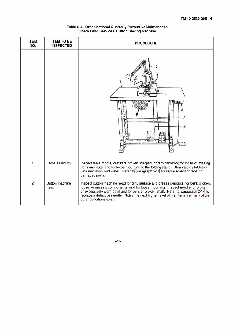
8/7/2019 TM 10-3530-205-10 CLOTHING REPAIR SHOP
http://slidepdf.com/reader/full/tm-10-3530-205-10-clothing-repair-shop 180/455
TM 10-3530-205-14
Table 5-4. Organizational Quarterly Preventive MaintenanceChecks and Services, Button Sewing Machine
ITEMNO.
ITEM TO BEINSPECTED
PROCEDURE
1 Table assembly Inspect table for cut, cracked, broken, warped, or dirty tabletop; for loose or missingbolts and nuts, and for loose mounting to the folding stand. Clean a dirty tabletopwith mild soap and water. Refer to paragraph 5-19 for replacement or repair ofdamaged parts.
2 Button machinehead
Inspect button machine head for dirty surface and grease deposits, for bent, broken,loose, or missing components; and for loose mounting. Inspect needle for brokenor excessively worn point and for bent or broken shaft. Refer to paragraph 2-14 toreplace a defective needle. Notify the next higher level of maintenance if any of theother conditions exist.
5-16
8/7/2019 TM 10-3530-205-10 CLOTHING REPAIR SHOP
http://slidepdf.com/reader/full/tm-10-3530-205-10-clothing-repair-shop 181/455
TM 10-3530-205-14
Table 5-4. Organizational Quarterly Preventive MaintenanceChecks and Services, Button Sewing Machine - Continued
ITEMNO.
ITEM TO BEINSPECTED
PROCEDURE
3 Thread unwinder Inspect thread unwinder for loose or missing bolts, nuts, and screws and for bent orbroken components. Notify next higher level of maintenance for replacement orrepair of damaged parts.
4 Drive belt andpulley
Inspect for broken, frayed, and excessively worn drive belt. Inspect belt for loosemounting on the pulleys. Inspect pulleys for cracked, chipped, or broken edges andfor loose mounting. Check for a 1/2-inch deflection of the belt midway between thepulleys. Notify next higher maintenance level if any of the other conditions exist.
5 Looper Tilt machine head on one side and inspect for broken looper point. Inspect looper,needle guide, and thread finger for improper adjustment. Notify next higher level ofmaintenance if any of the above conditions exist.
6 Motor switch Inspect for broken switch. Inspect it for loose mounting in the switchbox and makecertain it turns the motor on and off. Check for loose electrical connections orbroken wiring at switchbox. Notify next higher level of maintenance if any of theabove conditions exist.
7 Starting treadlechain
Inspect starting treadle chain for bent or broken links and loose mounting to thepulley shifter or the starting treadle. Press treadle and make certain pulley shifterengages with the machine drive pulley. Notify next higher maintenance level if anyof the above conditions exist.
8 Button clamp liftertreadle chainbutton clamp.
Inspect button clamp lifter treadle chain for bent or broken links and loose mountingto button clamp lifting rod and to button clamp lifter treadle. Press the treadle andmake certain lifting rod raises and lowers the
5-17
8/7/2019 TM 10-3530-205-10 CLOTHING REPAIR SHOP
http://slidepdf.com/reader/full/tm-10-3530-205-10-clothing-repair-shop 182/455
TM 10-3530-205-14
Table 5-4. Organizational Quarterly Preventive MaintenanceChecks and Services, Button Sewing Machine - Continued
ITEMNO.
ITEM TO BEINSPECTED
PROCEDURE
9 Electric motor Inspect motor for dirty surfaces and grease deposits, for bent, cracked, or brokenhousing; for loose or missing bolts and nuts, for loose electrical connections, forfrayed insulation and broken wiring, for improper and for loose mounting. Notifynext higher maintenance level if any other of the above conditions exist. Clean adirty motor by wiping with a clean, soft cloth (A ppendix E, i tem 3). Tighten loosemounting hardware.
5-18
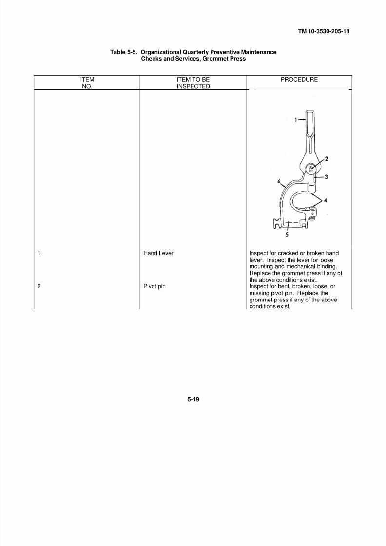
8/7/2019 TM 10-3530-205-10 CLOTHING REPAIR SHOP
http://slidepdf.com/reader/full/tm-10-3530-205-10-clothing-repair-shop 183/455
TM 10-3530-205-14
Table 5-5. Organizational Quarterly Preventive MaintenanceChecks and Services, Grommet Press
ITEM ITEM TO BE PROCEDURE
NO. INSPECTED
1 Hand Lever Inspect for cracked or broken handlever. Inspect the lever for loosemounting and mechanical binding.Replace the grommet press if any ofthe above conditions exist.
2 Pivot pin Inspect for bent, broken, loose, ormissing pivot pin. Replace thegrommet press if any of the aboveconditions exist.
5-19
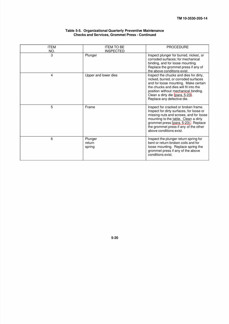
8/7/2019 TM 10-3530-205-10 CLOTHING REPAIR SHOP
http://slidepdf.com/reader/full/tm-10-3530-205-10-clothing-repair-shop 184/455
TM 10-3530-205-14
Table 5-5. Organizational Quarterly Preventive MaintenanceChecks and Services, Grommet Press - Continued
ITEM ITEM TO BE PROCEDURE
NO. INSPECTED3 Plunger Inspect plunger for burred, nicked, orcorroded surfaces; for mechanicalbinding, and for loose mounting.Replace the grommet press if any ofthe above conditions exist.
4 Upper and lower dies Inspect the chucks and dies for dirty,nicked, burred, or corroded surfacesand for loose mounting. Make certainthe chucks and dies will fit into theposition without mechanical binding.Clean a dirty die (para. 5-23) .Replace any defective die.
5 Frame Inspect for cracked or broken frame.Inspect for dirty surfaces, for loose ormissing nuts and screws, and for loosemounting to the table. Clean a dirtygrommet press ( para. 5-23). Replacethe grommet press if any of the otherabove conditions exist.
6 Plungerreturnspring
Inspect the plunger return spring forbent or return broken coils and forloose mounting. Replace spring thegrommet press if any of the aboveconditions exist.
5-20
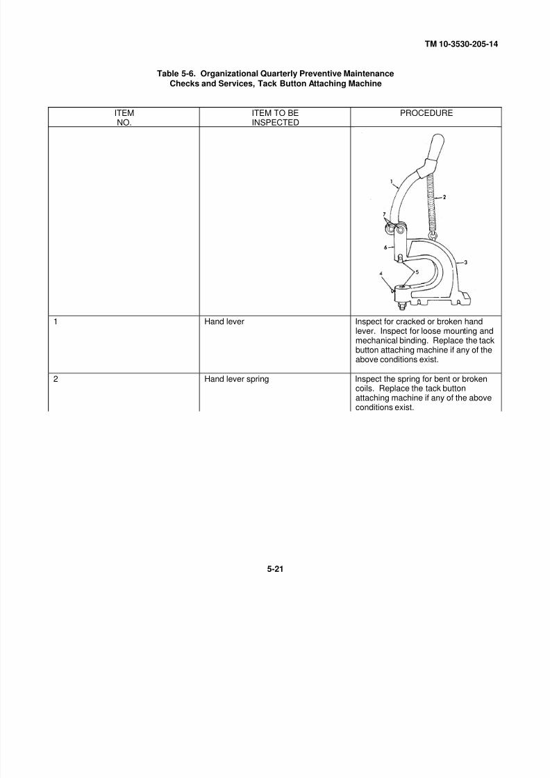
8/7/2019 TM 10-3530-205-10 CLOTHING REPAIR SHOP
http://slidepdf.com/reader/full/tm-10-3530-205-10-clothing-repair-shop 185/455
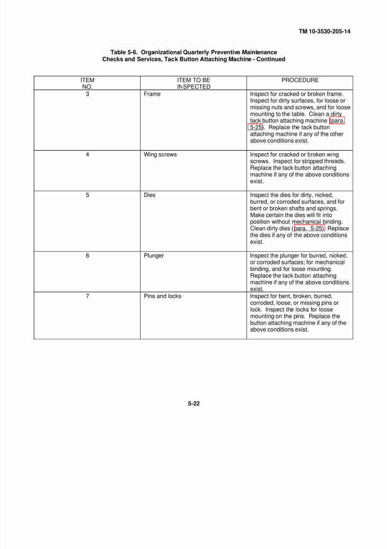
8/7/2019 TM 10-3530-205-10 CLOTHING REPAIR SHOP
http://slidepdf.com/reader/full/tm-10-3530-205-10-clothing-repair-shop 186/455
TM 10-3530-205-14
Table 5-6. Organizational Quarterly Preventive MaintenanceChecks and Services, Tack Button Attaching Machine - Continued
ITEM ITEM TO BE PROCEDURE
NO. INSPECTED3 Frame Inspect for cracked or broken frame.Inspect for dirty surfaces, for loose ormissing nuts and screws, and for loosemounting to the table. Clean a dirtytack button attaching machine (para.5-25) . Replace the tack buttonattaching machine if any of the otherabove conditions exist.
4 Wing screws Inspect for cracked or broken wingscrews. Inspect for stripped threads.Replace the tack button attaching
machine if any of the above conditionsexist.
5 Dies Inspect the dies for dirty, nicked,burred, or corroded surfaces, and forbent or broken shafts and springs.Make certain the dies will fit intoposition without mechanical binding.Clean dirty dies ( para. 5-25). Replacethe dies if any of the above conditionsexist.
6 Plunger Inspect the plunger for burred, nicked,or corroded surfaces; for mechanicalbinding, and for loose mounting.Replace the tack button attachingmachine if any of the above conditionsexist.
7 Pins and locks Inspect for bent, broken, burred,corroded, loose, or missing pins orlock. Inspect the locks for loosemounting on the pins. Replace thebutton attaching machine if any of theabove conditions exist.
5-22
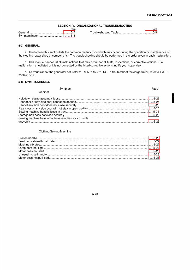
8/7/2019 TM 10-3530-205-10 CLOTHING REPAIR SHOP
http://slidepdf.com/reader/full/tm-10-3530-205-10-clothing-repair-shop 187/455
TM 10-3530-205-14
SECTION IV. ORGANIZATIONAL TROUBLESHOOTINGPara. Para.
General................................ ........... ........ 5-7 Troubleshooting Table................................ .........5-9Symptom Index ................................ ....... 5-8
5-7. GENERAL.
a. The table in this section lists the common malfunctions which may occur during the operation or maintenance ofthe clothing repair shop or components. The troubleshooting should be performed in the order given in each malfunction.
b. This manual cannot list all malfunctions that may occur nor all tests, inspections, or corrective actions. If amalfunction is not listed or it is not corrected by the listed corrective actions, notify your supervisor.
c. To troubleshoot the generator set, refer to TM 5-6115-271-14. To troubleshoot the cargo trailer, refer to TM 9-2330-213-14.
5-8. S YMPTOM INDEX.
Symptom PageCabinet
Holddown clamp assembly loose................................ ................................ ................................ ............. ..... 5-25Rear door or any side door cannot be opened................................ ................................ ......................... ..... 5-25Rear of any side door does not close securely................................ ................................ ......................... ..... 5-25Rear door or any side door will not stay in open position ................................ ................................ .......... .... 5-26Sewing machine head is loose in tray................................ ................................ ................................ ...... .....5-26Storage box does not close securely................................ ................................ ................................ ...... ...... 5-26Sewing machine trays or table assemblies stick or slideunevenly ................................ ................................ ................................ ................................ ................. ..... 5-26
Clothing Sewing Machine
Broken needle................................ ................................ ................................ ................................ ......... ..... 5-26Feed dogs strike throat plate................................ ................................ ................................ ................... ..... 5-27Machine vibrates................................ ................................ ................................ ................................ ..... ..... 5-27Lamp does not light ................................ ................................ ................................ ................................ .....5-27Motor does not start ................................ ................................ ................................ ............................... . ....5-28Unusual noise in motor................................ ................................ ................................ ............................ ... 5-28Motor does not pull load................................ ................................ ................................ .......................... ..... 5-28
5-23
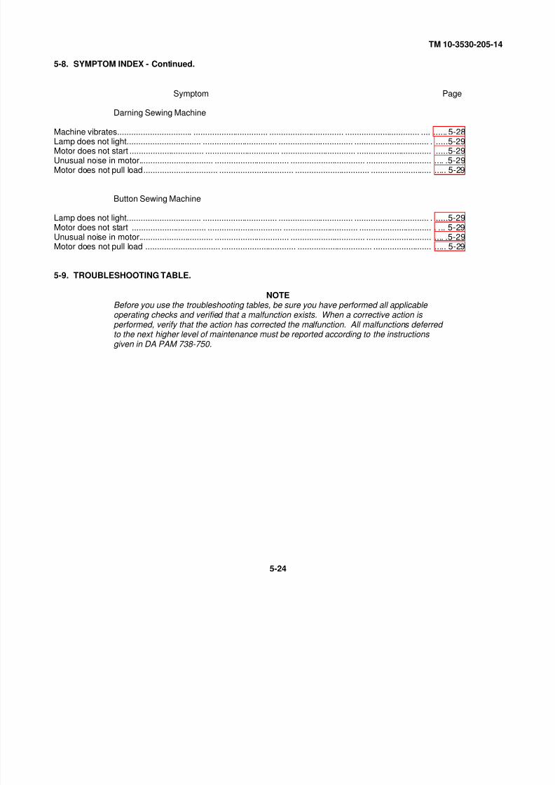
8/7/2019 TM 10-3530-205-10 CLOTHING REPAIR SHOP
http://slidepdf.com/reader/full/tm-10-3530-205-10-clothing-repair-shop 188/455
TM 10-3530-205-14
5-8. SYMPTOM INDEX - Continued.
Symptom Page
Darning Sewing Machine
Machine vibrates................................ ................................ ................................ ................................ .... ...... 5-28Lamp does not light................................ ................................ ................................ ................................ . .....5-29Motor does not start ................................ ................................ ................................ ................................ .....5-29Unusual noise in motor................................ ................................ ................................ ............................ .... .5-29Motor does not pull load................................ ................................ ................................ .......................... ..... 5-29
Button Sewing Machine
Lamp does not light................................ ................................ ................................ ................................ . .....5-29Motor does not start ................................ ................................ ................................ ............................... . ... 5-29Unusual noise in motor................................ ................................ ................................ ............................ .... .5-29Motor does not pull load ................................ ................................ ................................ ......................... ..... 5-29
5-9. T ROUBLESHOOTING TABLE.
NOTEBefore you use the troubleshooting tables, be sure you have performed all applicable operating checks and verified that a malfunction exists. When a corrective action is performed, verify that the action has corrected the malfunction. All malfunctions deferred to the next higher level of maintenance must be reported according to the instructions given in DA PAM 738-750.
5-24
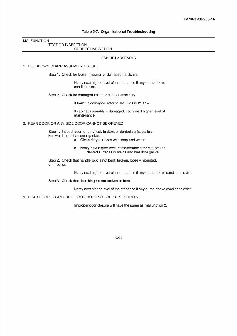
8/7/2019 TM 10-3530-205-10 CLOTHING REPAIR SHOP
http://slidepdf.com/reader/full/tm-10-3530-205-10-clothing-repair-shop 189/455
TM 10-3530-205-14
Table 5-7. Organizational Troubleshooting
MALFUNCTIONTEST OR INSPECTION
CORRECTIVE ACTION
CABINET ASSEMBLY
1. HOLDDOWN CLAMP ASSEMBLY LOOSE.
Step 1. Check for loose, missing, or damaged hardware.
Notify next higher level of maintenance if any of the aboveconditions exist.
Step 2. Check for damaged trailer or cabinet assembly.
If trailer is damaged, refer to TM 9-2330-213-14.
If cabinet assembly is damaged, notify next higher level ofmaintenance.
2. REAR DOOR OR ANY SIDE DOOR CANNOT BE OPENED.
Step 1. Inspect door for dirty, cut, broken, or dented surfaces; bro-ken welds, or a bad door gasket.
a. Clean dirty surfaces with soap and water.
b. Notify next higher level of maintenance for cut, broken,dented surfaces or welds and bad door gasket.
Step 2. Check that handle lock is not bent, broken, loosely mounted,or missing.
Notify next higher level of maintenance if any of the above conditions exist.
Step 3. Check that door hinge is not broken or bent.
Notify next higher level of maintenance if any of the above conditions exist.
3. REAR DOOR OR ANY SIDE DOOR DOES NOT CLOSE SECURELY.
Improper door closure will have the same as malfunction 2.
5-25
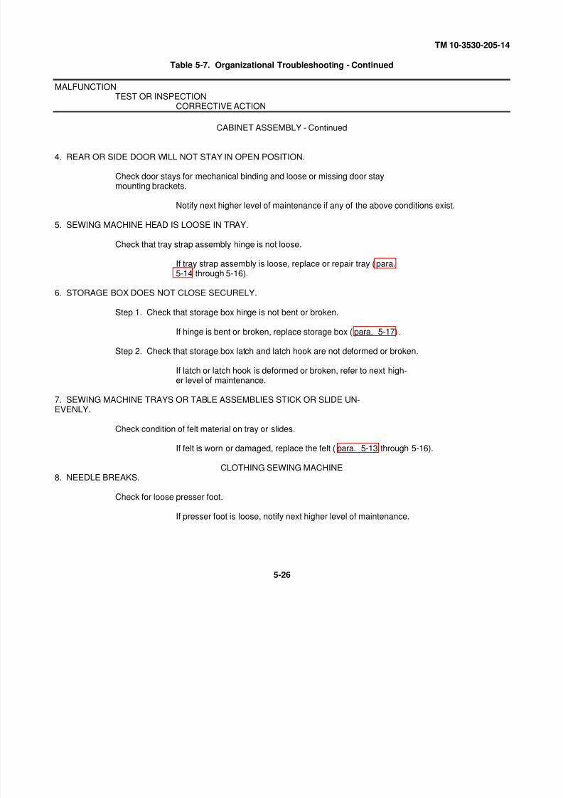
8/7/2019 TM 10-3530-205-10 CLOTHING REPAIR SHOP
http://slidepdf.com/reader/full/tm-10-3530-205-10-clothing-repair-shop 190/455
TM 10-3530-205-14
Table 5-7. Organizational Troubleshooting - Continued
MALFUNCTIONTEST OR INSPECTION
CORRECTIVE ACTION
CABINET ASSEMBLY - Continued
4. REAR OR SIDE DOOR WILL NOT STAY IN OPEN POSITION.
Check door stays for mechanical binding and loose or missing door staymounting brackets.
Notify next higher level of maintenance if any of the above conditions exist.
5. SEWING MACHINE HEAD IS LOOSE IN TRAY.
Check that tray strap assembly hinge is not loose.
If tray strap assembly is loose, replace or repair tray ( para.5-14 through 5-16).
6. STORAGE BOX DOES NOT CLOSE SECURELY.
Step 1. Check that storage box hinge is not bent or broken.
If hinge is bent or broken, replace storage box ( para. 5-17) .
Step 2. Check that storage box latch and latch hook are not deformed or broken.
If latch or latch hook is deformed or broken, refer to next high-er level of maintenance.
7. SEWING MACHINE TRAYS OR TABLE ASSEMBLIES STICK OR SLIDE UN-EVENLY.
Check condition of felt material on tray or slides.
If felt is worn or damaged, replace the felt ( para. 5-13 through 5-16).
CLOTHING SEWING MACHINE8. NEEDLE BREAKS.
Check for loose presser foot.
If presser foot is loose, notify next higher level of maintenance.
5-26
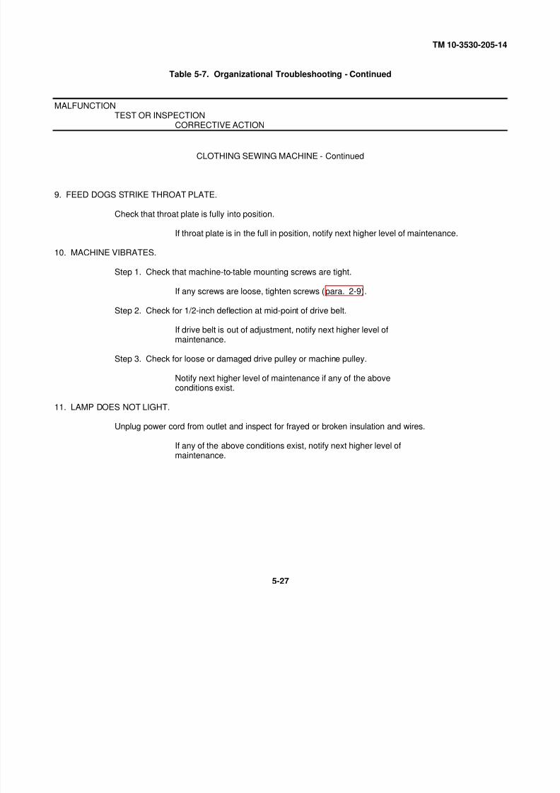
8/7/2019 TM 10-3530-205-10 CLOTHING REPAIR SHOP
http://slidepdf.com/reader/full/tm-10-3530-205-10-clothing-repair-shop 191/455
TM 10-3530-205-14
Table 5-7. Organizational Troubleshooting - Continued
MALFUNCTIONTEST OR INSPECTION
CORRECTIVE ACTION
CLOTHING SEWING MACHINE - Continued
9. FEED DOGS STRIKE THROAT PLATE.
Check that throat plate is fully into position.
If throat plate is in the full in position, notify next higher level of maintenance.
10. MACHINE VIBRATES.Step 1. Check that machine-to-table mounting screws are tight.
If any screws are loose, tighten screws ( para. 2-9) .
Step 2. Check for 1/2-inch deflection at mid-point of drive belt.
If drive belt is out of adjustment, notify next higher level ofmaintenance.
Step 3. Check for loose or damaged drive pulley or machine pulley.
Notify next higher level of maintenance if any of the aboveconditions exist.
11. LAMP DOES NOT LIGHT.
Unplug power cord from outlet and inspect for frayed or broken insulation and wires.
If any of the above conditions exist, notify next higher level ofmaintenance.
5-27
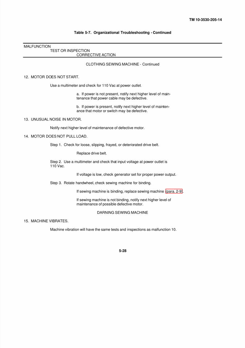
8/7/2019 TM 10-3530-205-10 CLOTHING REPAIR SHOP
http://slidepdf.com/reader/full/tm-10-3530-205-10-clothing-repair-shop 192/455
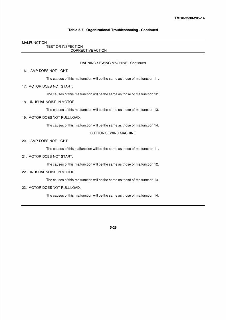
8/7/2019 TM 10-3530-205-10 CLOTHING REPAIR SHOP
http://slidepdf.com/reader/full/tm-10-3530-205-10-clothing-repair-shop 193/455
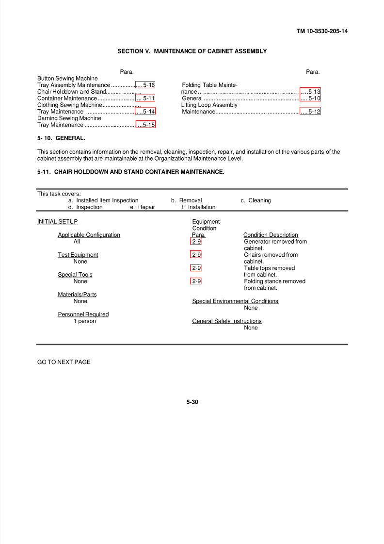
8/7/2019 TM 10-3530-205-10 CLOTHING REPAIR SHOP
http://slidepdf.com/reader/full/tm-10-3530-205-10-clothing-repair-shop 194/455
TM 10-3530-205-14
SECTION V. MAINTENANCE OF CABINET ASSEMBLY
Para. Para.Button Sewing Machine
Tray Assembly Maintenance ............... .... 5-16 Folding Table Mainte-Chair Holddown and Stand...................... nance................................ .............................. .. ..5-13Container Maintenance........................ ... 5-11 General ................................ ........................... .... 5-10Clothing Sewing Machine ........................ Lifting Loop AssemblyTray Maintenance .............................. .. ..5-14 Maintenance................................ .................... .... 5-12Darning Sewing MachineTray Maintenance ................................ ...5-15
5- 10. G ENERAL.
This section contains information on the removal, cleaning, inspection, repair, and installation of the various parts of thecabinet assembly that are maintainable at the Organizational Maintenance Level.
5-11. C HAIR HOLDDOWN AND STAND CONTAINER MAINTENANCE.
This task covers:a. Installed Item Inspection b. Removal c. Cleaningd. Inspection e. Repair f. Installation
INITIAL SETUP EquipmentCondition
Applicable Configuration Para. Condition DescriptionAll 2-9 Generator removed from
cabinet.Test Equipment 2-9 Chairs removed from
None cabinet.2-9 Table tops removedSpecial Tools from cabinet.
None 2-9 Folding stands removedfrom cabinet.
Materials/PartsNone Special Environmental Conditions
NonePersonnel Required
1 person General Safety InstructionsNone
GO TO NEXT PAGE
5-30
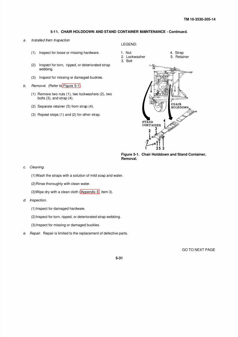
8/7/2019 TM 10-3530-205-10 CLOTHING REPAIR SHOP
http://slidepdf.com/reader/full/tm-10-3530-205-10-clothing-repair-shop 195/455
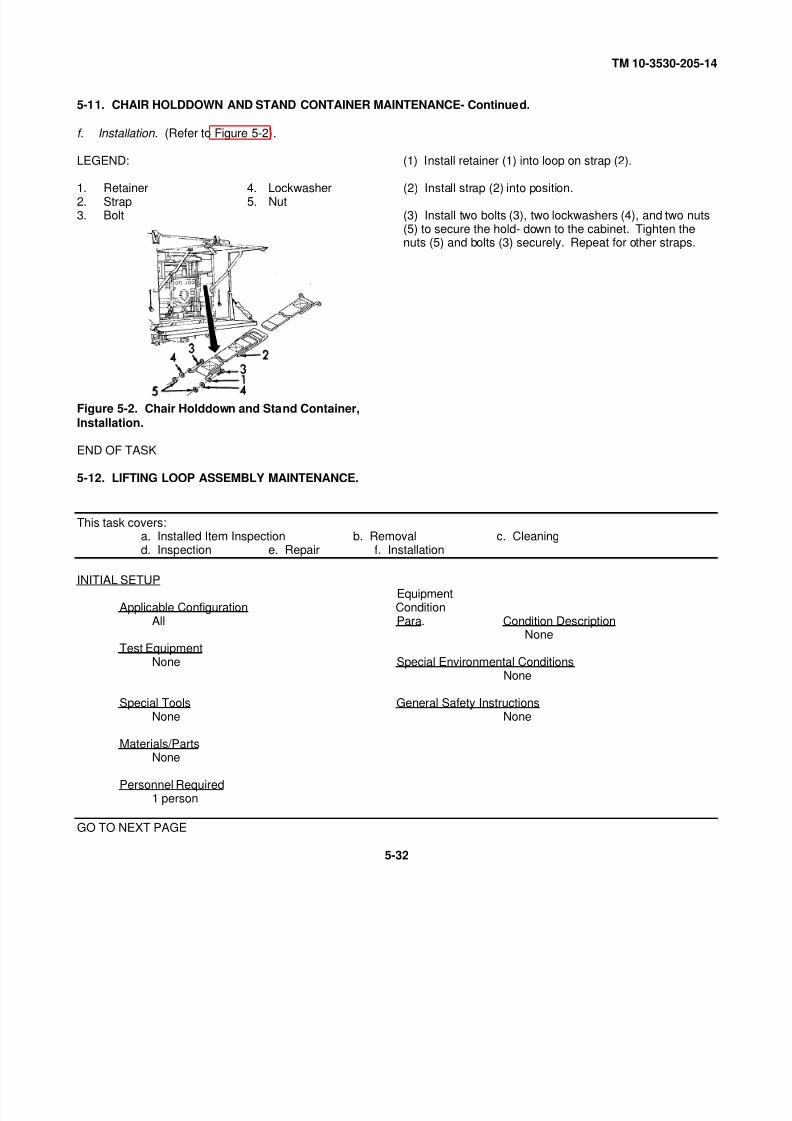
8/7/2019 TM 10-3530-205-10 CLOTHING REPAIR SHOP
http://slidepdf.com/reader/full/tm-10-3530-205-10-clothing-repair-shop 196/455
TM 10-3530-205-14
5-11. CHAIR HOLDDOWN AND STAND CONTAINER MAINTENANCE- Continued.
f. Installation. (Refer to Figure 5-2) .
LEGEND: (1) Install retainer (1) into loop on strap (2).
1. Retainer 4. Lockwasher2. Strap 5. Nut3. Bolt
Figure 5-2. Chair Holddown and Stand Container,Installation.
(2) Install strap (2) into position.
(3) Install two bolts (3), two lockwashers (4), and two nuts(5) to secure the hold- down to the cabinet. Tighten thenuts (5) and bolts (3) securely. Repeat for other straps.
END OF TASK
5-12. L IFTING LOOP ASSEMBLY MAINTENANCE.
This task covers:a. Installed Item Inspection b. Removal c. Cleaningd. Inspection e. Repair f. Installation
INITIAL SETUPEquipment
Applicable Configuration ConditionAll Para. Condition Description
NoneTest Equipment
None Special Environmental ConditionsNone
Special Tools General Safety InstructionsNone None
Materials/PartsNone
Personnel Required1 person
GO TO NEXT PAGE
5-32
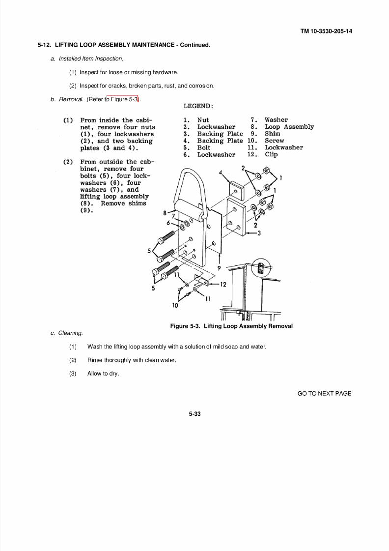
8/7/2019 TM 10-3530-205-10 CLOTHING REPAIR SHOP
http://slidepdf.com/reader/full/tm-10-3530-205-10-clothing-repair-shop 197/455
TM 10-3530-205-14
5-12. LIFTING LOOP ASSEMBLY MAINTENANCE - Continued.
a. Installed Item Inspection.
(1) Inspect for loose or missing hardware.
(2) Inspect for cracks, broken parts, rust, and corrosion.b. Removal. (Refer t o Figure 5-3) .
Figure 5-3. Lifting Loop Assembly Removalc. Cleaning.
(1) Wash the lifting loop assembly with a solution of mild soap and water.
(2) Rinse thoroughly with clean water.
(3) Allow to dry.
GO TO NEXT PAGE
5-33
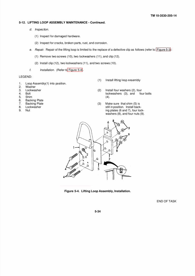
8/7/2019 TM 10-3530-205-10 CLOTHING REPAIR SHOP
http://slidepdf.com/reader/full/tm-10-3530-205-10-clothing-repair-shop 198/455
TM 10-3530-205-14
5-12. LIFTING LOOP ASSEMBLY MAINTENANCE - Continued.
d. Inspection.
(1) Inspect for damaged hardware.
(2) Inspect for cracks, broken parts, rust, and corrosion.e. Repair. Repair of the lifting loop is limited to the replace of a defective clip as follows (refer to Figure 5-3) :
(1) Remove two screws (10), two lockwashers (11), and clip (12).
(2) Install clip (12), two lockwashers (11), and two screws (10).
f. Installation. (Refer to Figure 5-4) .
LEGEND:(1) Install lifting loop assembly
1. Loop Assembly(1) into position.2. Washer3. Lockwasher (2) Install four washers (2), four4. Bolt lockwashers (3), and four bolts5. Shim (4).6. Backing Plate7. Backing Plate (3) Make sure that shim (5) is8. Lockwasher still in position. Install back-9. Nut ing plates (6 and 7), four lock-
washers (8), and four nuts (9).
Figure 5-4. Lifting Loop Assembly, Installation.
END OF TASK
5-34
8/7/2019 TM 10-3530-205-10 CLOTHING REPAIR SHOP
http://slidepdf.com/reader/full/tm-10-3530-205-10-clothing-repair-shop 199/455
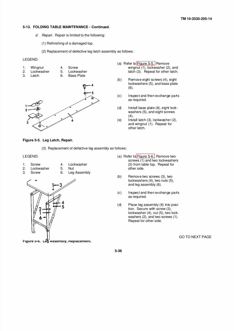
8/7/2019 TM 10-3530-205-10 CLOTHING REPAIR SHOP
http://slidepdf.com/reader/full/tm-10-3530-205-10-clothing-repair-shop 200/455
TM 10-3530-205-14
5-13. FOLDING TABLE MAINTENANCE - Continued.
d. Repair. Repair is limited to the following:
(1) Refinishing of a damaged top.
(2) Replacement of defective leg latch assembly as follows:
LEGEND:(a) Refer to Figure 5-5. Remove
1. Wingnut 4. Screw wingnut (1), lockwasher (2), and2. Lockwasher 5. Lockwasher latch (3). Repeat for other latch.3. Latch 6. Base Plate
(b) Remove eight screws (4), eightlockwashers (5), and base plate(6).
(c) Inspect and then exchange partsas required.
(d) Install base plate (6), eight lock-washers (5), and eight screws(4).
(e) Install latch (3), lockwasher (2),and wingnut (1). Repeat forother latch.
Figure 5-5. Leg Latch, Repair.
(3) Replacement of defective leg assembly as follows:
LEGEND: (a) Refer to Figure 5-6. Remove twoscrews (1) and two lockwashers
1. Screw 4. Lockwasher (2) from table top. Repeat for2. Lockwasher 5. Nut other side.3. Screw 6. Leg Assembly
(b) Remove two screws (3), twolockwashers (4), two nuts (5),and leg assembly (6).
(c) Inspect and then exchange partsas required.
(d) Place leg assembly (6) into posi-tion. Secure with screw (3),
lockwasher (4), nut (5), two lock-washers (2), and two screws (1).Repeat for other side.
GO TO NEXT PAGEFigure 5-6. Leg Assembly, Replacement.
5-36
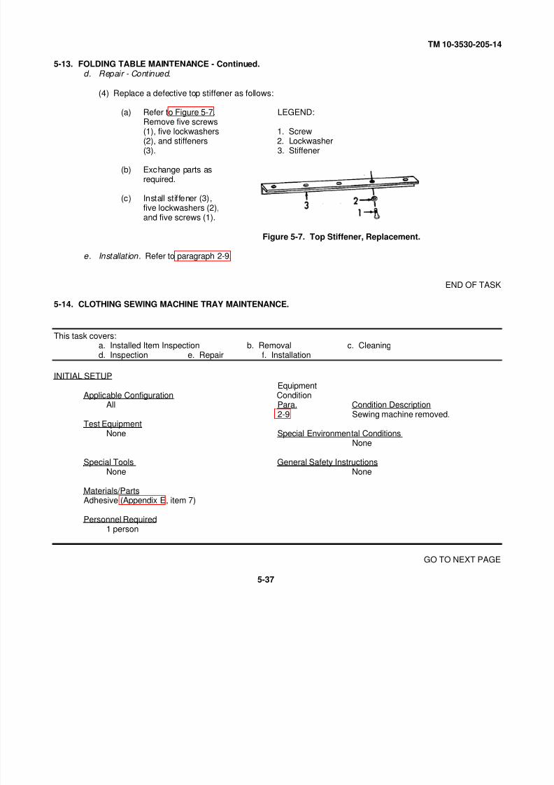
8/7/2019 TM 10-3530-205-10 CLOTHING REPAIR SHOP
http://slidepdf.com/reader/full/tm-10-3530-205-10-clothing-repair-shop 201/455
TM 10-3530-205-14
5-13. FOLDING TABLE MAINTENANCE - Continued.d. Repair - Continued.
(4) Replace a defective top stiffener as follows:
(a) Refer t o Figure 5-7. LEGEND:Remove five screws(1), five lockwashers 1. Screw(2), and stiffeners 2. Lockwasher(3). 3. Stiffener
(b) Exchange parts asrequired.
(c) Install stiffener (3),five lockwashers (2),and five screws (1).
Figure 5-7. Top Stiffener, Replacement.
e. Installation. Refer to paragraph 2-9.
END OF TASK
5-14. C LOTHING SEWING MACHINE TRAY MAINTENANCE.
This task covers:a. Installed Item Inspection b. Removal c. Cleaningd. Inspection e. Repair f. Installation
INITIAL SETUP EquipmentApplicable Configuration Condition
All Para. Condition Description2-9 Sewing machine removed.
Test EquipmentNone Special Environmental Conditions
None
Special Tools General Safety InstructionsNone None
Materials/PartsAdhesive (Appendix E , item 7)
Personnel Required1 person
GO TO NEXT PAGE
5-37
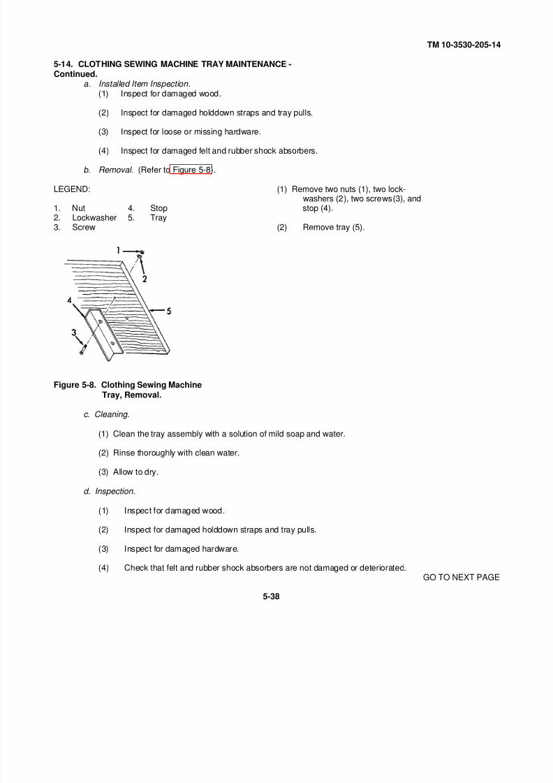
8/7/2019 TM 10-3530-205-10 CLOTHING REPAIR SHOP
http://slidepdf.com/reader/full/tm-10-3530-205-10-clothing-repair-shop 202/455
TM 10-3530-205-14
5-14. CLOTHING SEWING MACHINE TRAY MAINTENANCE -Continued.
a. Installed Item Inspection.(1) Inspect for damaged wood.
(2) Inspect for damaged holddown straps and tray pulls.
(3) Inspect for loose or missing hardware.
(4) Inspect for damaged felt and rubber shock absorbers.
b. Removal. (Refer to Figure 5-8) .
LEGEND: (1) Remove two nuts (1), two lock-washers (2), two screws (3), and
1. Nut 4. Stop stop (4).2. Lockwasher 5. Tray3. Screw (2) Remove tray (5).
Figure 5-8. Clothing Sewing MachineTray, Removal.
c. Cleaning.
(1) Clean the tray assembly with a solution of mild soap and water.
(2) Rinse thoroughly with clean water.
(3) Allow to dry.
d. Inspection.
(1) Inspect for damaged wood.
(2) Inspect for damaged holddown straps and tray pulls.
(3) Inspect for damaged hardware.
(4) Check that felt and rubber shock absorbers are not damaged or deteriorated.GO TO NEXT PAGE
5-38
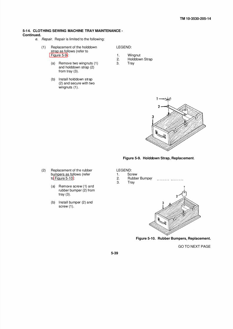
8/7/2019 TM 10-3530-205-10 CLOTHING REPAIR SHOP
http://slidepdf.com/reader/full/tm-10-3530-205-10-clothing-repair-shop 203/455
TM 10-3530-205-14
5-14. CLOTHING SEWING MACHINE TRAY MAINTENANCE -Continued.
e. Repair. Repair is limited to the following:
(1) Replacement of the holddown LEGEND:
strap as follows (refer toFigure 5-9) : 1. Wingnut2. Holddown Strap
(a) Remove two wingnuts (1) 3. Trayand holddown strap (2)from tray (3).
(b) Install holddown strap(2) and secure with twowingnuts (1).
Figure 5-9. Holddown Strap, Replacement .
(2) Replacement of the rubber LEGEND:bumpers as follows (refer 1. Screwto Figure 5-10) : 2. Rubber Bumper
3. Tray(a) Remove screw (1) and
rubber bumper (2) fromtray (3).
(b) Install bumper (2) andscrew (1).
Figure 5-10. Rubber Bumpers, Replacement.
GO TO NEXT PAGE
5-39
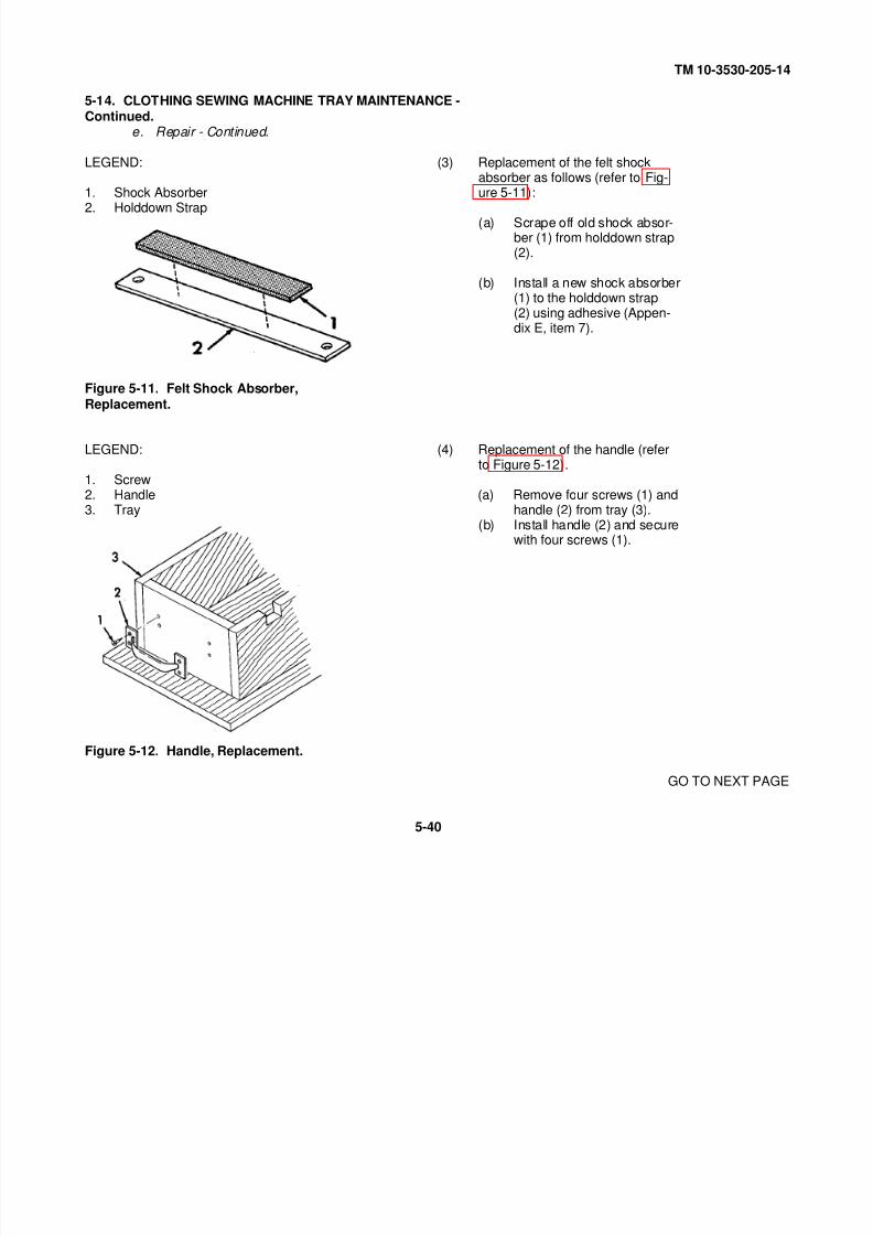
8/7/2019 TM 10-3530-205-10 CLOTHING REPAIR SHOP
http://slidepdf.com/reader/full/tm-10-3530-205-10-clothing-repair-shop 204/455
TM 10-3530-205-14
5-14. CLOTHING SEWING MACHINE TRAY MAINTENANCE -Continued.
e. Repair - Continued.
LEGEND: (3) Replacement of the felt shockabsorber as follows (refer to Fig-
1. Shock Absorber ure 5-11) :2. Holddown Strap(a) Scrape off old shock absor-
ber (1) from holddown strap(2).
(b) Install a new shock absorber(1) to the holddown strap(2) using adhesive (Appen-dix E, item 7).
Figure 5-11. Felt Shock Absorber,Replacement.
LEGEND: (4) Replacement of the handle (referto Figure 5-12) .
1. Screw2. Handle (a) Remove four screws (1) and3. Tray handle (2) from tray (3).
(b) Install handle (2) and securewith four screws (1).
Figure 5-12. Handle, Replacement.
GO TO NEXT PAGE
5-40
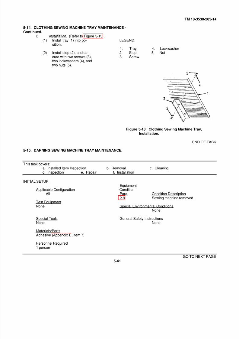
8/7/2019 TM 10-3530-205-10 CLOTHING REPAIR SHOP
http://slidepdf.com/reader/full/tm-10-3530-205-10-clothing-repair-shop 205/455
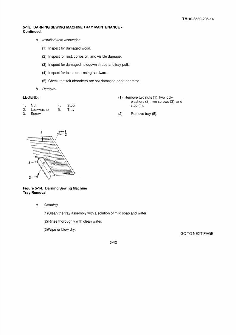
8/7/2019 TM 10-3530-205-10 CLOTHING REPAIR SHOP
http://slidepdf.com/reader/full/tm-10-3530-205-10-clothing-repair-shop 206/455
TM 10-3530-205-14
5-15. DARNING SEWING MACHINE TRAY MAINTENANCE -Continued.
a. Installed Item Inspection.
(1) Inspect for damaged wood.
(2) Inspect for rust, corrosion, and visible damage.
(3) Inspect for damaged holddown straps and tray pulls.
(4) Inspect for loose or missing hardware.
(5) Check that felt absorbers are not damaged or deteriorated.
b. Removal.
LEGEND: (1) Remove two nuts (1), two lock-washers (2), two screws (3), and
1. Nut 4. Stop stop (4).2. Lockwasher 5. Tray3. Screw (2) Remove tray (5).
Figure 5-14. Darning Sewing MachineTray Removal
c. Cleaning.
(1)Clean the tray assembly with a solution of mild soap and water.
(2)Rinse thoroughly with clean water.
(3)Wipe or blow dry.GO TO NEXT PAGE
5-42
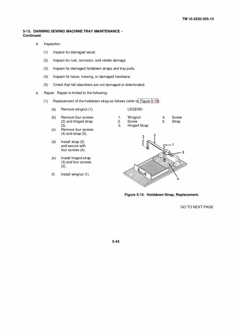
8/7/2019 TM 10-3530-205-10 CLOTHING REPAIR SHOP
http://slidepdf.com/reader/full/tm-10-3530-205-10-clothing-repair-shop 207/455
TM 10-3530-205-14
5-15. DARNING SEWING MACHINE TRAY MAINTENANCE -Continued.
d. Inspection.
(1) Inspect for damaged wood.(2) Inspect for rust, corrosion, and visible damage.
(3) Inspect for damaged holddown straps and tray pulls.
(4) Inspect for loose, missing, or damaged hardware.
(5) Check that felt absorbers are not damaged or deteriorated.
e. Repair. Repair is limited to the following:
(1) Replacement of the holddown strap as follows (refer to Figure 5-15) .
(a) Remove wingnut (1). LEGEND:
(b) Remove four screws 1. Wingnut 4. Screw(2) and hinged strap 2. Screw 5. Strap(3). 3. Hinged Strap
(c) Remove four screws(4) and strap (5).
(d) Install strap (5)and secure withfour screws (4).
(e) Install hinged strap(3) and four screws(2).
(f) Install wingnut (1).
Figure 5-15. Holddown Strap, Replacement.
GO TO NEXT PAGE
5-43
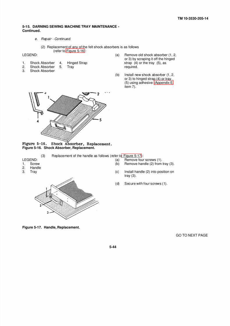
8/7/2019 TM 10-3530-205-10 CLOTHING REPAIR SHOP
http://slidepdf.com/reader/full/tm-10-3530-205-10-clothing-repair-shop 208/455
TM 10-3530-205-14
5-15. DARNING SEWING MACHINE TRAY MAINTENANCE -Continued.
e. Repair - Continued.
(2) Replacement of any of the felt shock absorbers is as follows
(refer to Figure 5-16) :LEGEND: (a) Remove old shock absorber (1, 2,or 3) by scraping it off the hinged
1. Shock Absorber 4. Hinged Strap strap (4) or the tray (5), as2. Shock Absorber 5. Tray required.3. Shock Absorber
(b) Install new shock absorber (1, 2,or 3) to hinged strap (4) or tray(5) using adhesive (Appendix E,item 7).
Figure 5-16. Shock Absorber, Replacement.
(3) Replacement of the handle as follows (refer to Figure 5-17) :LEGEND: (a) Remove four screws (1).1. Screw (b) Remove handle (2) from tray (3).2. Handle3. Tray (c) Install handle (2) into position on
tray (3).
(d) Secure with four screws (1).
Figure 5-17. Handle, Replacement.
GO TO NEXT PAGE
5-44
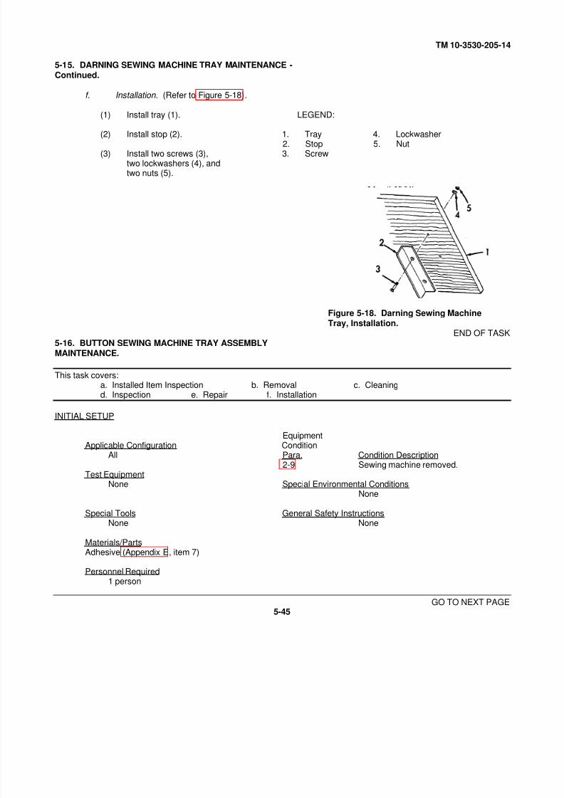
8/7/2019 TM 10-3530-205-10 CLOTHING REPAIR SHOP
http://slidepdf.com/reader/full/tm-10-3530-205-10-clothing-repair-shop 209/455
TM 10-3530-205-14
5-15. DARNING SEWING MACHINE TRAY MAINTENANCE -Continued.
f. Installation. (Refer to Figure 5-18) .
(1) Install tray (1). LEGEND:
(2) Install stop (2). 1. Tray 4. Lockwasher2. Stop 5. Nut
(3) Install two screws (3), 3. Screwtwo lockwashers (4), andtwo nuts (5).
Figure 5-18. Darning Sewing MachineTray, Installation.
END OF TASK5-16. B UTTON SEWING MACHINE TRAY ASSEMBLYMAINTENANCE.
This task covers:
a. Installed Item Inspection b. Removal c. Cleaningd. Inspection e. Repair f. Installation
INITIAL SETUP
EquipmentApplicable Configuration Condition
All Para. Condition Description2-9 Sewing machine removed.
Test EquipmentNone Special Environmental Conditions
None
Special Tools General Safety InstructionsNone None
Materials/PartsAdhesive (Appendix E , item 7)
Personnel Required1 person
GO TO NEXT PAGE5-45
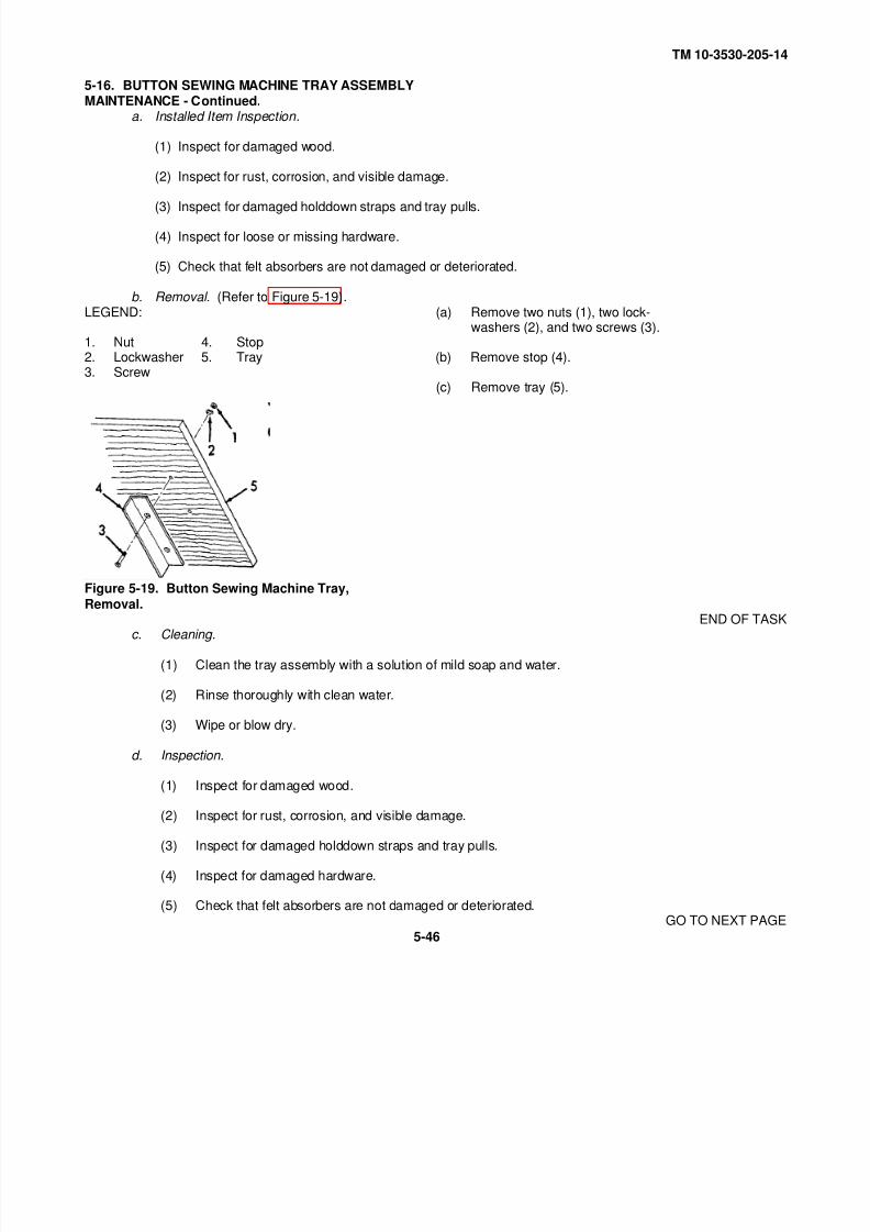
8/7/2019 TM 10-3530-205-10 CLOTHING REPAIR SHOP
http://slidepdf.com/reader/full/tm-10-3530-205-10-clothing-repair-shop 210/455
TM 10-3530-205-14
5-16. BUTTON SEWING MACHINE TRAY ASSEMBLYMAINTENANCE - Continued.
a. Installed Item Inspection.
(1) Inspect for damaged wood.
(2) Inspect for rust, corrosion, and visible damage.
(3) Inspect for damaged holddown straps and tray pulls.
(4) Inspect for loose or missing hardware.
(5) Check that felt absorbers are not damaged or deteriorated.
b. Removal. (Refer to Figure 5-19) .LEGEND: (a) Remove two nuts (1), two lock-
washers (2), and two screws (3).1. Nut 4. Stop2. Lockwasher 5. Tray (b) Remove stop (4).3. Screw
(c) Remove tray (5).
Figure 5-19. Button Sewing Machine Tray,Removal.
END OF TASKc. Cleaning.
(1) Clean the tray assembly with a solution of mild soap and water.
(2) Rinse thoroughly with clean water.
(3) Wipe or blow dry.
d. Inspection.
(1) Inspect for damaged wood.
(2) Inspect for rust, corrosion, and visible damage.
(3) Inspect for damaged holddown straps and tray pulls.
(4) Inspect for damaged hardware.
(5) Check that felt absorbers are not damaged or deteriorated.GO TO NEXT PAGE
5-46
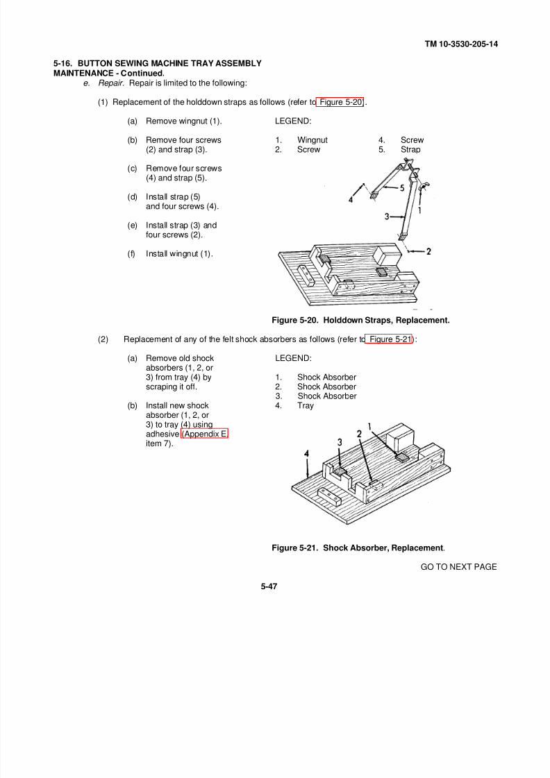
8/7/2019 TM 10-3530-205-10 CLOTHING REPAIR SHOP
http://slidepdf.com/reader/full/tm-10-3530-205-10-clothing-repair-shop 211/455
TM 10-3530-205-14
5-16. BUTTON SEWING MACHINE TRAY ASSEMBLYMAINTENANCE - Continued.
e. Repair. Repair is limited to the following:
(1) Replacement of the holddown straps as follows (refer to Figure 5-20) .
(a) Remove wingnut (1). LEGEND:(b) Remove four screws 1. Wingnut 4. Screw
(2) and strap (3). 2. Screw 5. Strap
(c) Remove four screws(4) and strap (5).
(d) Install strap (5)and four screws (4).
(e) Install strap (3) andfour screws (2).
(f) Install wingnut (1).
Figure 5-20. Holddown Straps, Replacement.
(2) Replacement of any of the felt shock absorbers as follows (refer to Figure 5-21) :
(a) Remove old shock LEGEND:absorbers (1, 2, or3) from tray (4) by 1. Shock Absorberscraping it off. 2. Shock Absorber
3. Shock Absorber(b) Install new shock 4. Tray
absorber (1, 2, or3) to tray (4) usingadhesive (Appendix E,item 7).
Figure 5-21. Shock Absorber, Replacement .
GO TO NEXT PAGE
5-47
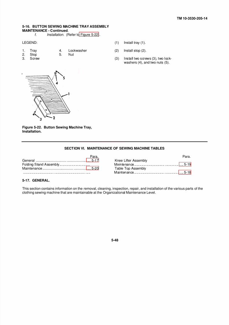
8/7/2019 TM 10-3530-205-10 CLOTHING REPAIR SHOP
http://slidepdf.com/reader/full/tm-10-3530-205-10-clothing-repair-shop 212/455
TM 10-3530-205-14
5-16. BUTTON SEWING MACHINE TRAY ASSEMBLYMAINTENANCE - Continued.
f. Installation. (Refer to Figure 5-22) .
LEGEND: (1) Install tray (1).
1. Tray 4. Lockwasher (2) Install stop (2).2. Stop 5. Nut3. Screw (3) Install two screws (3), two lock-
washers (4), and two nuts (5).
Figure 5-22. Button Sewing Machine Tray,Installation.
SECTION VI. MAINTENANCE OF SEWING MACHINE TABLES
Para. Para.General ................................ .................... .... 5-17 Knee Lifter AssemblyFolding Stand Assembly................................ Maintenance................................ .............. .... 5-19Maintenance ................................ ............. .... 5-20 Table Top Assembly................................ ................................ ..... Maintenance................................ .............. .... 5-18
5-17. G ENERAL.
This section contains information on the removal, cleaning, inspection, repair, and installation of the various parts of theclothing sewing machine that are maintainable at the Organizational Maintenance Level.
5-48
8/7/2019 TM 10-3530-205-10 CLOTHING REPAIR SHOP
http://slidepdf.com/reader/full/tm-10-3530-205-10-clothing-repair-shop 213/455
TM 10-3530-205-14
5-18. TABLE TOP ASSEMBLY MAINTENANCE.
This task covers:a. Removal b. Cleaning c. Repair d. Installation
INITIAL SETUPEquipment
Applicable Configuration ConditionAll Para. Condition Description
2-9 Table top removed.
Test EquipmentNone Special Environmental Conditions
None
Special Tools General Safety InstructionsNone None
Materials/PartsNone
Personnel Required1 person
a. Removal. Refer to paragraph 2-9.
b. Cleaning.
(1) Clean the table top assembly with a solution of mild soap and water. Do not wash the motor.
(2) Rinse thoroughly with clean water.
(3) Allow to dry.
c. Repair. Repair at the organizational level is limited to the following:
(1) Replacement of the machine rest pin (paragraph 2-9) .
(2) Replacement of the oil drip pan (paragraph 2-9) .
(3) Replacement of the bobbin winder (paragraph 2-9) .
(4) Replacement of the thread unwinder assembly (paragraph 2-9) .
d. Installation. Refer to paragraph 2-9.
END OF TASK
5-49
8/7/2019 TM 10-3530-205-10 CLOTHING REPAIR SHOP
http://slidepdf.com/reader/full/tm-10-3530-205-10-clothing-repair-shop 214/455
TM 10-3530-205-14
5-19. KNEE LIFTER ASSEMBLY MAINTENANCE.
This task covers:a. Installed Item Inspection b. Removal c. Cleaningd. Inspection e. Repair f. Installation
INITIAL SETUP
EquipmentApplicable Configuration ConditionAll Para. Condition Description
2-9 Clothing sewing machineremoved.
Test EquipmentNone Special Environmental Conditions
None
Special Tools Personnel RequiredNone 1 person
Materials/PartsBrush(Appendix E , item 1)
Cleaning Solvent(Appendix E , item 2)
Cloth(Appendix E , item 3)
General Safety Instructions
WARNING
Cleaning solvent, Federal Specification P-D-680, is both toxic and flammable. Keep off skin. Use only in a well- ventilated area and avoid prolonged breathing of vapors.Keep away from open flame.
a. Installed Item Inspection.
(1) Inspect for loose or missing hardware.
(2) Inspect for rust/corrosion and damaged parts.
GO TO NEXT PAGE
5-50
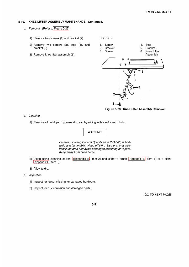
8/7/2019 TM 10-3530-205-10 CLOTHING REPAIR SHOP
http://slidepdf.com/reader/full/tm-10-3530-205-10-clothing-repair-shop 215/455
TM 10-3530-205-14
5-19. KNEE LIFTER ASSEMBLY MAINTENANCE - Continued.
b. Removal. (Refer to Figure 5-23) .
(1) Remove two screws (1) and bracket (2).
(2) Remove two screws (3), stop (4), andbracket (5).
(3) Remove knee lifter assembly (6).
LEGEND:
1. Screw 4. Stop2. Bracket 5. Bracket3. Screw 6. Knee Lifter
Assembly
Figure 5-23. Knee Lifter Assembly Removal.
c. Cleaning.
(1) Remove all buildups of grease, dirt, etc. by wiping with a soft clean cloth.
WARNING
Cleaning solvent, Federal Specification P-D-680, is both toxic and flammable. Keep off skin. Use only in a well- ventilated area and avoid prolonged breathing of vapors.Keep away from open flame.
(2) Clean using cleaning solvent (Appendix E, item 2) and either a brush (Appendix E, item 1) or a cloth(Appendix E , item 3).
(3) Allow to dry.
d. Inspection.
(1) Inspect for loose, missing, or damaged hardware.
(2) Inspect for rust/corrosion and damaged parts.
GO TO NEXT PAGE
5-51
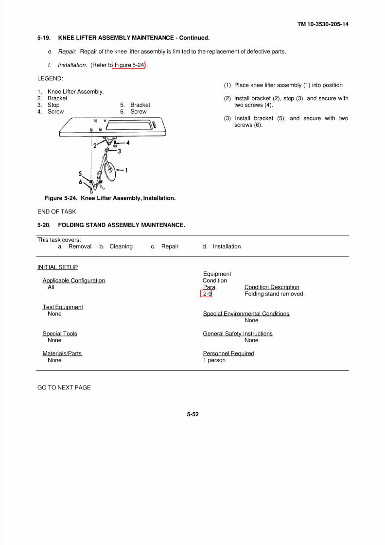
8/7/2019 TM 10-3530-205-10 CLOTHING REPAIR SHOP
http://slidepdf.com/reader/full/tm-10-3530-205-10-clothing-repair-shop 216/455
TM 10-3530-205-14
5-19. KNEE LIFTER ASSEMBLY MAINTENANCE - Continued.
e. Repair. Repair of the knee lifter assembly is limited to the replacement of defective parts.
f. Installation. (Refer to Figure 5-24) .
LEGEND:
1. Knee Lifter Assembly.2. Bracket3. Stop 5. Bracket4. Screw 6. Screw
Figure 5-24. Knee Lifter Assembly, Installation.
(1) Place knee lifter assembly (1) into position(2) Install bracket (2), stop (3), and secure with
two screws (4).
(3) Install bracket (5), and secure with twoscrews (6).
END OF TASK
5-20. FOLDING STAND ASSEMBLY MAINTENANCE.
This task covers:a. Removal b. Cleaning c. Repair d. Installation
INITIAL SETUPEquipment
Applicable Configuration ConditionAll Para. Condition Description
2-9 Folding stand removed.
Test EquipmentNone Special Environmental Conditions
None
Special Tools General Safety InstructionsNone None
Materials/Parts Personnel RequiredNone 1 person
GO TO NEXT PAGE
5-52
8/7/2019 TM 10-3530-205-10 CLOTHING REPAIR SHOP
http://slidepdf.com/reader/full/tm-10-3530-205-10-clothing-repair-shop 217/455
TM 10-3530-205-14
5-20. FOLDING STAND ASSEMBLY MAINTENANCE - Continued.
a. Removal. Refer to paragraph 2-9.
b. Cleaning.
(1) Clean the folding stand assembly with solution of mild soap and water.
(2) Rinse thoroughly with clean water.
(3) Allow to dry.
c. Repair. Repair of the folding stand assembly is limited to the replacement of defective hardware.
d. Installation. Refer to paragraph 2-17.
END OF TASK
SECTION VII. MAINTENANCE OF THE GROMMET PRESS
Para. Para.General ................................ ............ ..... 5-21 Grommet Press Mainte-
nance................................ ...................... ..... 5-22
5- 21. G ENERAL.
This section contains information on the removal, cleaning, inspection, repair, and installation of the grommet press.
5-53
8/7/2019 TM 10-3530-205-10 CLOTHING REPAIR SHOP
http://slidepdf.com/reader/full/tm-10-3530-205-10-clothing-repair-shop 218/455
TM 10-3530-205-14
5-22. GROMMET PRESS MAINTENANCE.
This task covers:a. Removal b. Cleaning c. Inspection d. Repaire. Installation
INITIAL SETUP
EquipmentApplicable Configuration ConditionAll Para. Condition Description
2-9 Table top removed.
Test EquipmentNone Special Environmental Conditions
None
Special Tools Personnel RequiredNone 1 person
Materials/PartsBrush(Appendix E , item 1)
Cleaning Solvent(Appendix E , item 2)
Cloth(Appendix E , item 3)
General Safety Instructions
WARNING
Cleaning solvent, Federal Specification P-D-680, is both toxic and flammable. Keep off skin. Use only in a well- ventilated area and avoid prolonged breathing of vapors.Keep away from open flame.
a. Removal. Refer t o Figure 2-9.
b. Cleaning.
(1) Remove all buildups of grease, dirt, etc. by wiping with a soft clean cloth.
WARNING
Cleaning solvent, Federal Specification P-D-680, is both toxic and flammable. Keep off skin. Use only in a well- ventilated area and avoid prolonged breathing of vapors.Keep away from open flame.
GO TO NEXT PAGE
5-54
8/7/2019 TM 10-3530-205-10 CLOTHING REPAIR SHOP
http://slidepdf.com/reader/full/tm-10-3530-205-10-clothing-repair-shop 219/455
8/7/2019 TM 10-3530-205-10 CLOTHING REPAIR SHOP
http://slidepdf.com/reader/full/tm-10-3530-205-10-clothing-repair-shop 220/455
TM 10-3530-205-14
5-24. TACK-BUTTON ATTACHING MACHINE MAINTENANCE.
This task covers:a. Removal b. Cleaning c. Inspection d. Repaire. Installation
INITIAL SETUP
EquipmentApplicable Configuration ConditionAll Para. Condition Description
2-9 Tack-button attachingmachine removed.
Test EquipmentNone Special Environmental Conditions
None
Special Tools Personnel RequiredNone 1 person
Materials/Parts
Brush1 person(Appendix E , item 1)Cleaning Solvent
(Appendix E , item 2)Cloth
(Appendix E , item 3)
General Safety Instructions
WARNING
Cleaning solvent, Federal Specification P-D-680, is both toxic and flammable. Keep off skin. Use only in a well- ventilated area and avoid prolonged breathing of vapors.Keep away from open flame.
a. Removal. Refer t o Figure 2-9.
b. Cleaning.
(1) Remove all buildups of grease, dirt, etc. by wiping with a soft clean cloth.
WARNING
Cleaning solvent, Federal Specification P-D-680, is both toxic and flammable. Keep off skin. Use only in a well- ventilated area and avoid prolonged breathing of vapors.Keep away from open flame.
GO TO NEXT PAGE
5-56
8/7/2019 TM 10-3530-205-10 CLOTHING REPAIR SHOP
http://slidepdf.com/reader/full/tm-10-3530-205-10-clothing-repair-shop 221/455
TM 10-3530-205-14
5-24. TACK-BUTTON ATTACHING MACHINE MAINTENANCE - Continued.
b. Cleaning - Continued.
(2) Clean using cleaning solvent (Appendix E, item 2) and either a brush (Appendix E, item 1) or a cloth(Appendix E , item 3).
(3) Allow to dry.
c. Inspection.
(1) Inspect for loose, missing, or damaged hardware.
(2) Inspect for rust/corrosion and damaged parts.
d. Repair. Repair of the tack-button attaching machine is limited to the replacement of the upper and lower dies.
e. Installation. Refer to paragraph 2-9.
END OF TASK
SECTION IX. PREPARATION FOR STORAGE OR SHIPMENT
5-25. G ENERAL.
Refer to TM 740-90-1, Administrative Storage of Equipment, and to TB 740-97-2, Preservation of Mechanical Equipmentfor Shipment and Storage.
5-57/5 -58 Blank

8/7/2019 TM 10-3530-205-10 CLOTHING REPAIR SHOP
http://slidepdf.com/reader/full/tm-10-3530-205-10-clothing-repair-shop 222/455
8/7/2019 TM 10-3530-205-10 CLOTHING REPAIR SHOP
http://slidepdf.com/reader/full/tm-10-3530-205-10-clothing-repair-shop 223/455
TM 10-3530-205-14
CHAPTER 6
DIRECT SUPPORT MAINTENANCE INSTRUCTIONS
Section I. REPAIR PARTS, SPECIAL TOOLS, TMDE, ANDSUPPORT EQUIPMENT
Section II. MAINTENANCE OF CABINET ASSEMBLYSection III. MAINTENANCE OF CLOTHING SEWING MACHINESection IV. MAINTENANCE OF DARNING SEWING MACHINESection V. MAINTENANCE OF BUTTON SEWING MACHINE
SECTION I. REPAIR PARTS, SPECIAL TOOLS, TMDE, ANDSUPPORT EQUIPMENT
Para. Para.Common Tools and Equipment...................... .... 6-1 Special Tools, TMDE, and
Repair Parts ................................ .................. .... 6-3 Support Equipment ................................ .....6-2
6-1. COMMON TOOLS AND EQUIPMENT.
For authorized common tools and equipment, refer to the Modified Table of Organization and Equipment (MTOE)applicable to your unit.
6-2. SPECIAL TOOLS, TMDE, AND SUPPORT EQUIPMENT.For the special tools, TMDE, or support equipment authorized for the maintenance of the clothing repair shop, refer toAppendix B, Maintenance Allocation Chart.
6-3. REPAIR PARTS.
Repair parts are listed and illustrated in the repair parts and special tools list TM 10-3530-205-24P coveringorganizational, direct support and general support, and depot maintenance for this equipment.
6-1
8/7/2019 TM 10-3530-205-10 CLOTHING REPAIR SHOP
http://slidepdf.com/reader/full/tm-10-3530-205-10-clothing-repair-shop 224/455
TM 10-3530-205-14
SECTION II. MAINTENANCE OF CABINET ASSEMBLY
Para. Para.Cabinet Assembly Power Cable
Maintenance ................................ ........... .... 6-5 Maintenance. ................................ ........... .... 6-10General ................................ ......................... .... 6-4 Rear Door Assembly
Generator Track and Holddown Maintenance................................ ............ .... 6-7Assembly Maintenance ........................... .... 6-9 Side Door AssemblyHolddown Clamp Assembly Maintenance ................................ ........... .... 6-6
Maintenance................................. ........... .... 6-8
6-4. GENERAL.
This section contains information on the removal, disassembly, cleaning, inspection, repair, assembly, and installation ofthe various parts of the cabinet assembly that are maintained at the Direct Support Maintenance Level.
6-5. CABINET ASSEMBLY MAINTENANCE.
This task covers:
a. Installed Item Inspection b. Removal c. Cleaningd. Inspection e. Repair f. Installation
INITIAL SETUPEquipment
Applicable Configuration ConditionAll Para. Condition Description
2-9 All equipment removed.Test Equipment 2-9 Rear and side doors
None closed.2-9 Hand brakes set.
Special Tools 2-9 Tailgate lowered.Hoist (5,000 lb. capacity) 2-9 Rear support leg low-
4 Chains (2,500 lb. capa- ered.city)4 Cargo Straps (15 ft. lg.)
Special Environmental ConditionsNone
Materials/PartsNone
Personnel Required1 person
General Safety Instructions
WARNING
Be sure that all personnel are standing clear of the cabinet. Do not allow anyone near the cabinet while it is off the trailer or the ground.
GO TO NEXT PAGE
6-2
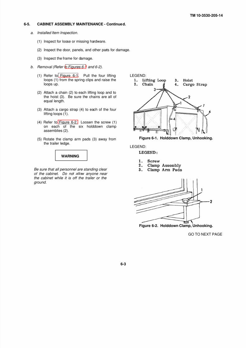
8/7/2019 TM 10-3530-205-10 CLOTHING REPAIR SHOP
http://slidepdf.com/reader/full/tm-10-3530-205-10-clothing-repair-shop 225/455
TM 10-3530-205-14
6-5. CABINET ASSEMBLY MAINTENANCE - Continued.
a. Installed Item Inspection.
(1) Inspect for loose or missing hardware.
(2) Inspect the door, panels, and other parts for damage.
(3) Inspect the frame for damage.
b. Removal (Refer t o Figures 6-1 and 6-2).
(1) Refer to Figure 6-1. Pull the four liftingloops (1) from the spring clips and raise theloops up.
(2) Attach a chain (2) to each lifting loop and tothe hoist (3). Be sure the chains are all ofequal length.
(3) Attach a cargo strap (4) to each of the fourlifting loops (1).
(4) Refer to Figure 6-2. Loosen the screw (1)on each of the six holddown clampassemblies (2).
(5) Rotate the clamp arm pads (3) away fromthe trailer ledge.
WARNING
Be sure that all personnel are standing clear of the cabinet. Do not allow anyone near the cabinet while it is off the trailer or the ground.
LEGEND:
Figure 6-1. Holddown Clamp, Unhooking.
LEGEND:
Figure 6-2. Holddown Clamp, Unhooking.
GO TO NEXT PAGE
6-3
8/7/2019 TM 10-3530-205-10 CLOTHING REPAIR SHOP
http://slidepdf.com/reader/full/tm-10-3530-205-10-clothing-repair-shop 226/455
TM 10-3530-205-14
6-5. CABINET ASSEMBLY MAINTENANCE - Continued.
b. Removal - Continued.
(6) Have one person hold the end of each of the four 15 foot cargo straps (4).
(7) With four persons steadying the cabinet by using the four cargo straps (4), slowly lift the cabinet off thetrailer.
(8) When the cabinet assembly is clear of the trailer, move the cabinet assembly to a suitable area, (such aswooden pallets or jack stands).
(9) Disconnect the chains and hoist from the lifting loops.
c. Cleaning.
(1) Clean the cabinet assembly with a solution of mild soap and water.
(2) Rinse thoroughly with clean water.
(3) Allow to dry.
d. Inspection.
(1) Inspect for loose, missing, or damaged hardware.
(2) Inspect the door, panels, and other parts for damage.
(3) Inspect the frame for damage.
e. Repair. Repair of the cabinet assembly is limited to those items in the maintenance paragraphs below.
f. Installation (Refer to Figures 6-3 and 6-4).
(1) Refer t o Figure 6-3 . Pull the four lifting loops (1) from the spring clips and raise the loops up.
(2) Attach a chain (2) to each loop (1) and the hoist (3). Be sure the chains are of equal length.
(3) Attach a cargo strap (4) to each lifting loop.
GO TO NEXT PAGE
6-4
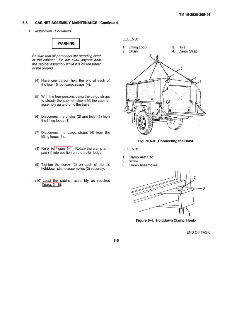
8/7/2019 TM 10-3530-205-10 CLOTHING REPAIR SHOP
http://slidepdf.com/reader/full/tm-10-3530-205-10-clothing-repair-shop 227/455
TM 10-3530-205-14
6-5. CABINET ASSEMBLY MAINTENANCE - Continued.
f. Installation - Continued.
WARNING
Be sure that all personnel are standing clear of the cabinet. Do not allow anyone near the cabinet assembly while it is off the trailer or the ground.
(4) Have one person hold the end of each ofthe four 15 foot cargo straps (4).
(5) With the four persons using the cargo strapsto steady the cabinet, slowly lift the cabinet
assembly up and onto the trailer.
(6) Disconnect the chains (2) and hoist (3) fromthe lifting loops (1).
(7) Disconnect the cargo straps (4) from thelifting loops (1).
(8) Refer to Figure 6-4. Rotate the clamp armpad (1) into position on the trailer ledge.
(9) Tighten the screw (2) on each of the sixholddown clamp assemblies (3) securely.
(10) Load the cabinet assembly as required(para. 2-16) .
LEGEND:
1. Lifting Loop 3. Hoist
2. Chain 4. Cargo Strap
Figure 6-3. Connecting the Hoist.
LEGEND:
1. Clamp Arm Pad2. Screw3. Clamp Assemblies
Figure 6-4. Holddown Clamp, Hook-
END OF TASK
6-5
8/7/2019 TM 10-3530-205-10 CLOTHING REPAIR SHOP
http://slidepdf.com/reader/full/tm-10-3530-205-10-clothing-repair-shop 228/455
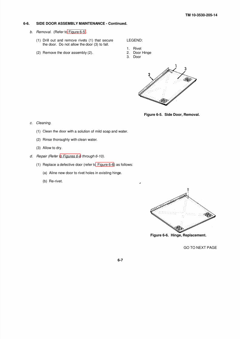
8/7/2019 TM 10-3530-205-10 CLOTHING REPAIR SHOP
http://slidepdf.com/reader/full/tm-10-3530-205-10-clothing-repair-shop 229/455
TM 10-3530-205-14
6-6. SIDE DOOR ASSEMBLY MAINTENANCE - Continued.
b. Removal. (Refer to Figure 6-5) .
(1) Drill out and remove rivets (1) that securethe door. Do not allow the door (3) to fall.
(2) Remove the door assembly (2).
LEGEND:
1. Rivet2. Door Hinge3. Door
Figure 6-5. Side Door, Removal.
c. Cleaning.
(1) Clean the door with a solution of mild soap and water.
(2) Rinse thoroughly with clean water.
(3) Allow to dry.
d. Repair (Refer t o Figures 6-6 through 6-10).
(1) Replace a defective door (refer to Figure 6-6 ) as follows:
(a) Aline new door to rivet holes in existing hinge.
(b) Re-rivet.
Figure 6-6. Hinge, Replacement.
GO TO NEXT PAGE
6-7
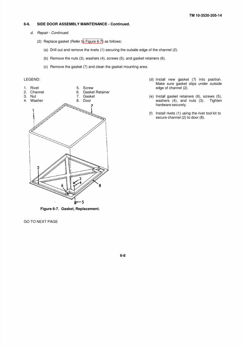
8/7/2019 TM 10-3530-205-10 CLOTHING REPAIR SHOP
http://slidepdf.com/reader/full/tm-10-3530-205-10-clothing-repair-shop 230/455
TM 10-3530-205-14
6-6. SIDE DOOR ASSEMBLY MAINTENANCE - Continued.
d. Repair - Continued.
(2) Replace gasket (Refer t o Figure 6-7 ) as follows:
(a) Drill out and remove the rivets (1) securing the outside edge of the channel (2).
(b) Remove the nuts (3), washers (4), screws (5), and gasket retainers (6).
(c) Remove the gasket (7) and clean the gasket mounting area.
LEGEND:
1. Rivet 5. Screw2. Channel 6. Gasket Retainer3. Nut 7. Gasket4. Washer 8. Door
Figure 6-7. Gasket, Replacement.
(d) Install new gasket (7) into position.Make sure gasket slips under outsideedge of channel (2).
(e) Install gasket retainers (6), screws (5),washers (4), and nuts (3). Tightenhardware securely.
(f) Install rivets (1) using the rivet tool kit tosecure channel (2) to door (8).
GO TO NEXT PAGE
6-8
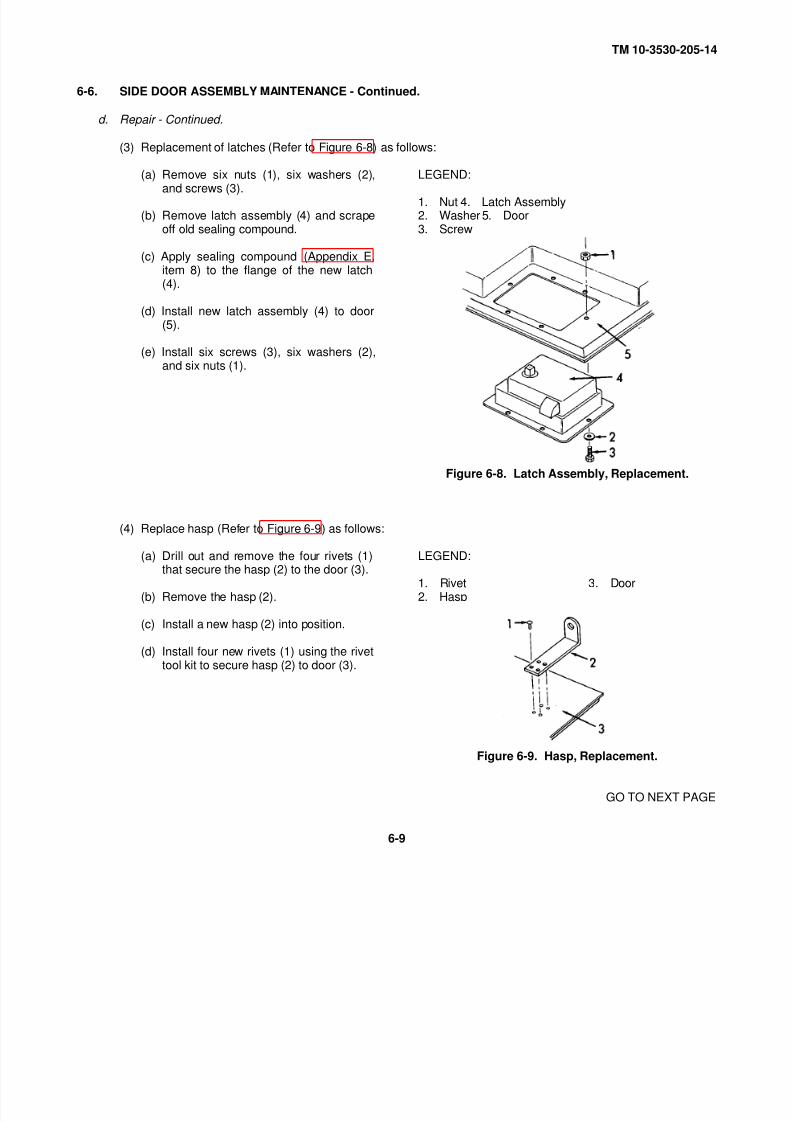
8/7/2019 TM 10-3530-205-10 CLOTHING REPAIR SHOP
http://slidepdf.com/reader/full/tm-10-3530-205-10-clothing-repair-shop 231/455
TM 10-3530-205-14
6-6. SIDE DOOR ASSEMBLY MAINTENANCE - Continued.
d. Repair - Continued.
(3) Replacement of latches (Refer to Figure 6-8) as follows:
(a) Remove six nuts (1), six washers (2),and screws (3).
(b) Remove latch assembly (4) and scrapeoff old sealing compound.
(c) Apply sealing compound (Appendix E,item 8) to the flange of the new latch(4).
(d) Install new latch assembly (4) to door(5).
(e) Install six screws (3), six washers (2),and six nuts (1).
LEGEND:1. Nut 4. Latch Assembly2. Washer 5. Door3. Screw
Figure 6-8. Latch Assembly, Replacement.
(4) Replace hasp (Refer to Figure 6-9 ) as follows:
(a) Drill out and remove the four rivets (1)that secure the hasp (2) to the door (3).
(b) Remove the hasp (2).
(c) Install a new hasp (2) into position.
(d) Install four new rivets (1) using the rivettool kit to secure hasp (2) to door (3).
LEGEND:
1. Rivet 3. Door2. Hasp
Figure 6-9. Hasp, Replacement.
GO TO NEXT PAGE
6-9
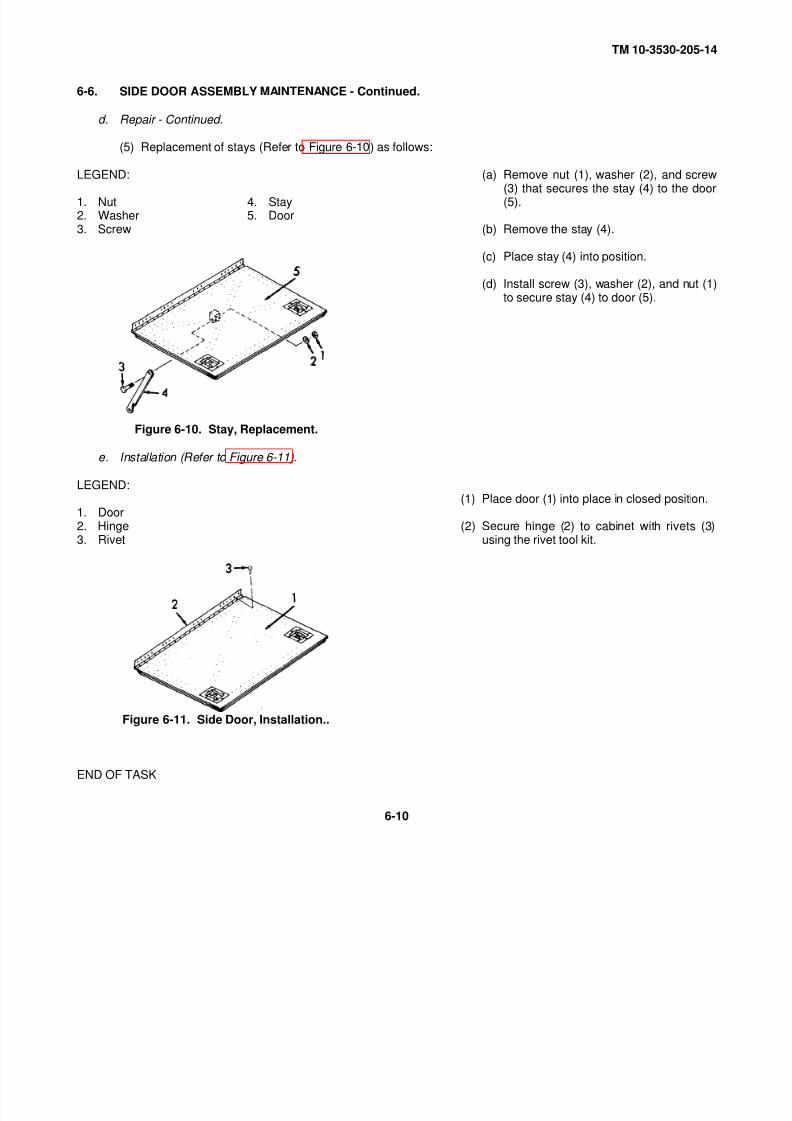
8/7/2019 TM 10-3530-205-10 CLOTHING REPAIR SHOP
http://slidepdf.com/reader/full/tm-10-3530-205-10-clothing-repair-shop 232/455
TM 10-3530-205-14
6-6. SIDE DOOR ASSEMBLY MAINTENANCE - Continued.
d. Repair - Continued.
(5) Replacement of stays (Refer to Figure 6-10 ) as follows:
LEGEND:1. Nut 4. Stay2. Washer 5. Door3. Screw
Figure 6-10. Stay, Replacement.
(a) Remove nut (1), washer (2), and screw(3) that secures the stay (4) to the door(5).
(b) Remove the stay (4).
(c) Place stay (4) into position.
(d) Install screw (3), washer (2), and nut (1)to secure stay (4) to door (5).
e. Installation (Refer to Figure 6-11) .
LEGEND:
1. Door2. Hinge
3. Rivet
Figure 6-11. Side Door, Installation..
(1) Place door (1) into place in closed position.
(2) Secure hinge (2) to cabinet with rivets (3)
using the rivet tool kit.
END OF TASK
6-10
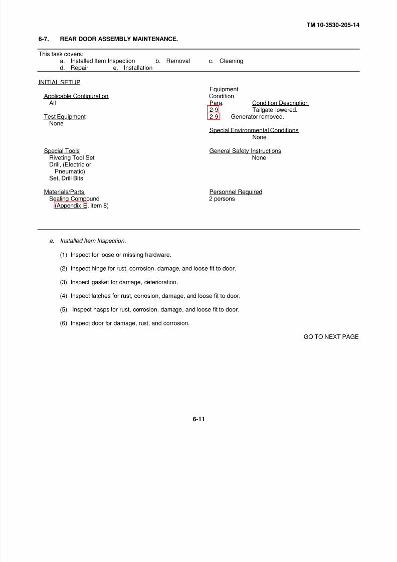
8/7/2019 TM 10-3530-205-10 CLOTHING REPAIR SHOP
http://slidepdf.com/reader/full/tm-10-3530-205-10-clothing-repair-shop 233/455
TM 10-3530-205-14
6-7. REAR DOOR ASSEMBLY MAINTENANCE.
This task covers:a. Installed Item Inspection b. Removal c. Cleaningd. Repair e. Installation
INITIAL SETUP
EquipmentApplicable Configuration ConditionAll Para. Condition Description
2-9 Tailgate lowered.Test Equipment 2-9 Generator removed.
NoneSpecial Environmental Conditions
None
Special Tools General Safety InstructionsRiveting Tool Set NoneDrill, (Electric or
Pneumatic)
Set, Drill BitsMaterials/Parts Personnel Required
Sealing Compound 2 persons(Appendix E , item 8)
a. Installed Item Inspection.
(1) Inspect for loose or missing hardware.
(2) Inspect hinge for rust, corrosion, damage, and loose fit to door.
(3) Inspect gasket for damage, deterioration.
(4) Inspect latches for rust, corrosion, damage, and loose fit to door.
(5) Inspect hasps for rust, corrosion, damage, and loose fit to door.
(6) Inspect door for damage, rust, and corrosion.
GO TO NEXT PAGE
6-11
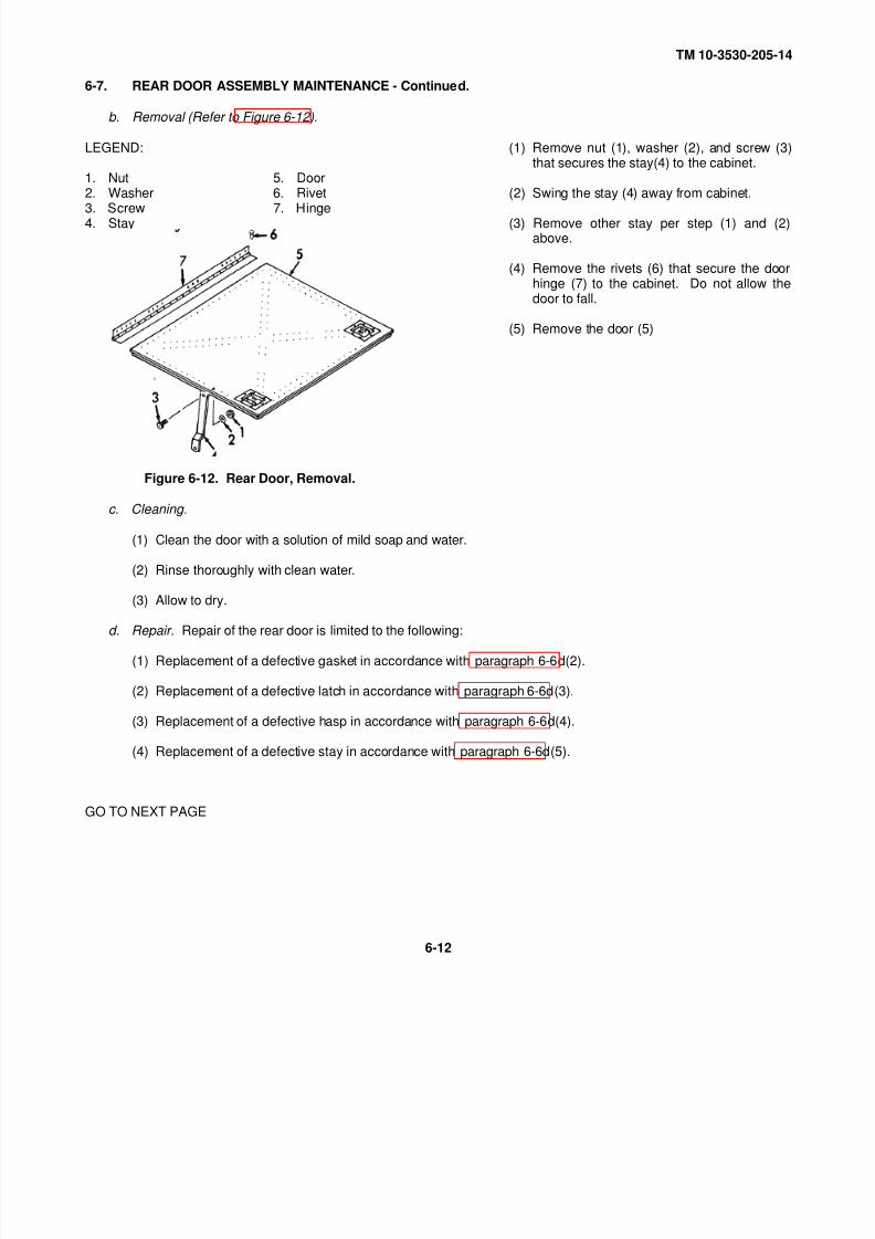
8/7/2019 TM 10-3530-205-10 CLOTHING REPAIR SHOP
http://slidepdf.com/reader/full/tm-10-3530-205-10-clothing-repair-shop 234/455
TM 10-3530-205-14
6-7. REAR DOOR ASSEMBLY MAINTENANCE - Continued.
b. Removal (Refer to Figure 6-12) .
LEGEND:
1. Nut 5. Door
2. Washer 6. Rivet3. Screw 7. Hinge4. Stay
Figure 6-12. Rear Door, Removal.
(1) Remove nut (1), washer (2), and screw (3)that secures the stay(4) to the cabinet.
(2) Swing the stay (4) away from cabinet.(3) Remove other stay per step (1) and (2)
above.
(4) Remove the rivets (6) that secure the doorhinge (7) to the cabinet. Do not allow thedoor to fall.
(5) Remove the door (5)
c. Cleaning.
(1) Clean the door with a solution of mild soap and water.
(2) Rinse thoroughly with clean water.
(3) Allow to dry.
d. Repair. Repair of the rear door is limited to the following:
(1) Replacement of a defective gasket in accordance with paragraph 6-6 d(2).
(2) Replacement of a defective latch in accordance with paragraph 6-6d (3).
(3) Replacement of a defective hasp in accordance with paragraph 6-6 d(4).
(4) Replacement of a defective stay in accordance with paragraph 6-6d (5).
GO TO NEXT PAGE
6-12
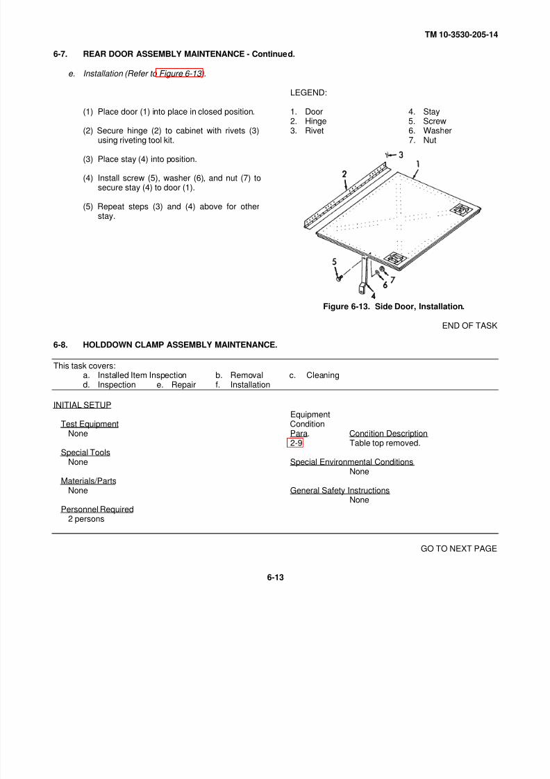
8/7/2019 TM 10-3530-205-10 CLOTHING REPAIR SHOP
http://slidepdf.com/reader/full/tm-10-3530-205-10-clothing-repair-shop 235/455
TM 10-3530-205-14
6-7. REAR DOOR ASSEMBLY MAINTENANCE - Continued.
e. Installation (Refer to Figure 6-13) .
(1) Place door (1) into place in closed position.
(2) Secure hinge (2) to cabinet with rivets (3)using riveting tool kit.
(3) Place stay (4) into position.
(4) Install screw (5), washer (6), and nut (7) tosecure stay (4) to door (1).
(5) Repeat steps (3) and (4) above for otherstay.
LEGEND:
1. Door 4. Stay
2. Hinge 5. Screw3. Rivet 6. Washer7. Nut
Figure 6-13. Side Door, Installation.
END OF TASK
6-8. HOLDDOWN CLAMP ASSEMBLY MAINTENANCE.
This task covers:
a. Installed Item Inspection b. Removal c. Cleaningd. Inspection e. Repair f. Installation
INITIAL SETUPEquipment
Test Equipment ConditionNone Para. Condition Description
2-9 Table top removed.Special Tools
None Special Environmental ConditionsNone
Materials/PartsNone General Safety Instructions
NonePersonnel Required2 persons
GO TO NEXT PAGE
6-13
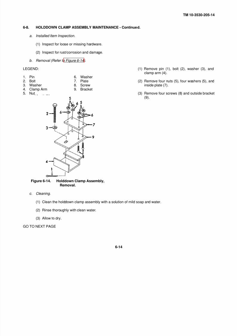
8/7/2019 TM 10-3530-205-10 CLOTHING REPAIR SHOP
http://slidepdf.com/reader/full/tm-10-3530-205-10-clothing-repair-shop 236/455
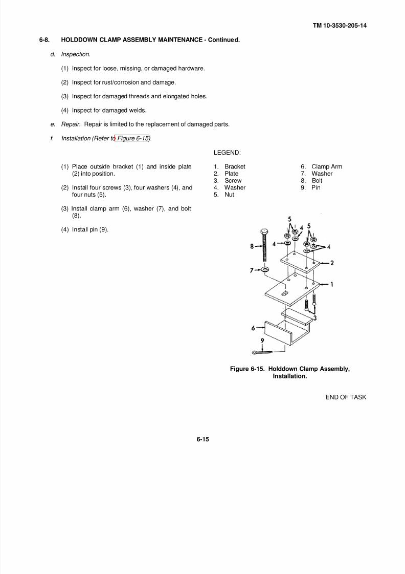
8/7/2019 TM 10-3530-205-10 CLOTHING REPAIR SHOP
http://slidepdf.com/reader/full/tm-10-3530-205-10-clothing-repair-shop 237/455
TM 10-3530-205-14
6-8. HOLDDOWN CLAMP ASSEMBLY MAINTENANCE - Continued.
d. Inspection.
(1) Inspect for loose, missing, or damaged hardware.
(2) Inspect for rust/corrosion and damage.
(3) Inspect for damaged threads and elongated holes.
(4) Inspect for damaged welds.
e. Repair. Repair is limited to the replacement of damaged parts.
f. Installation (Refer to Figure 6-15) .
(1) Place outside bracket (1) and inside plate(2) into position.
(2) Install four screws (3), four washers (4), andfour nuts (5).
(3) Install clamp arm (6), washer (7), and bolt(8).
(4) Install pin (9).
LEGEND:
1. Bracket 6. Clamp Arm2. Plate 7. Washer3. Screw 8. Bolt4. Washer 9. Pin5. Nut
Figure 6-15. Holddown Clamp Assembly,Installation.
END OF TASK
6-15
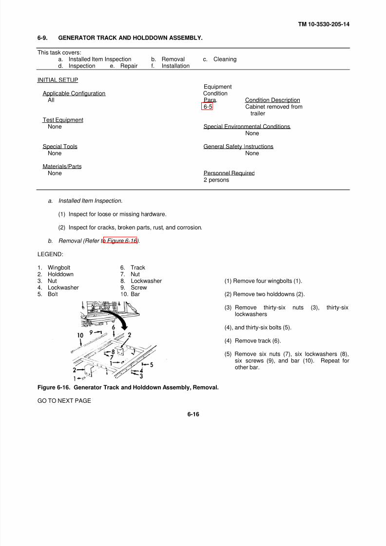
8/7/2019 TM 10-3530-205-10 CLOTHING REPAIR SHOP
http://slidepdf.com/reader/full/tm-10-3530-205-10-clothing-repair-shop 238/455
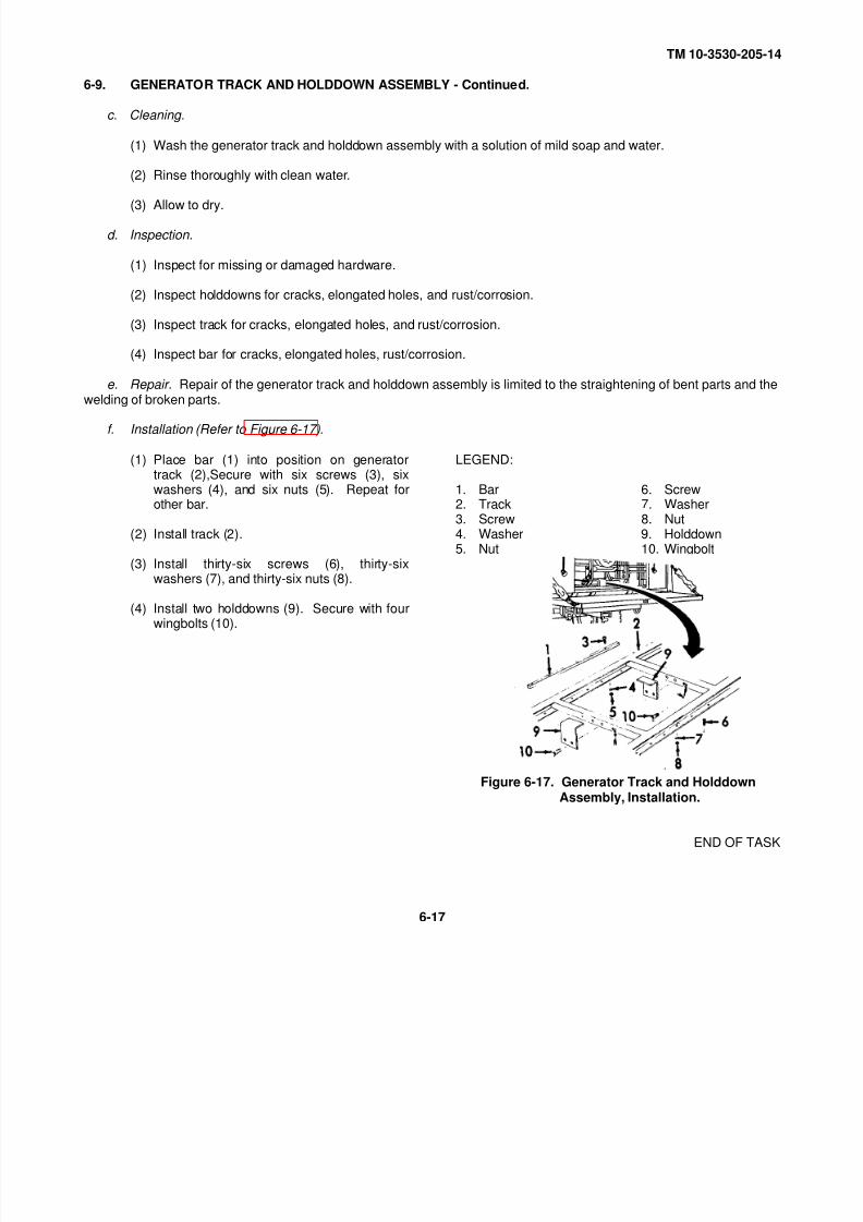
8/7/2019 TM 10-3530-205-10 CLOTHING REPAIR SHOP
http://slidepdf.com/reader/full/tm-10-3530-205-10-clothing-repair-shop 239/455
TM 10-3530-205-14
6-9. GENERATOR TRACK AND HOLDDOWN ASSEMBLY - Continued.
c. Cleaning.
(1) Wash the generator track and holddown assembly with a solution of mild soap and water.
(2) Rinse thoroughly with clean water.
(3) Allow to dry.
d. Inspection.
(1) Inspect for missing or damaged hardware.
(2) Inspect holddowns for cracks, elongated holes, and rust/corrosion.
(3) Inspect track for cracks, elongated holes, and rust/corrosion.
(4) Inspect bar for cracks, elongated holes, rust/corrosion.
e. Repair. Repair of the generator track and holddown assembly is limited to the straightening of bent parts and thewelding of broken parts.
f. Installation (Refer to Figure 6-17) .
(1) Place bar (1) into position on generatortrack (2),Secure with six screws (3), sixwashers (4), and six nuts (5). Repeat forother bar.
(2) Install track (2).
(3) Install thirty-six screws (6), thirty-sixwashers (7), and thirty-six nuts (8).
(4) Install two holddowns (9). Secure with fourwingbolts (10).
LEGEND:
1. Bar 6. Screw2. Track 7. Washer3. Screw 8. Nut4. Washer 9. Holddown5. Nut 10. Wingbolt
Figure 6-17. Generator Track and HolddownAssembly, Installation.
END OF TASK
6-17
8/7/2019 TM 10-3530-205-10 CLOTHING REPAIR SHOP
http://slidepdf.com/reader/full/tm-10-3530-205-10-clothing-repair-shop 240/455
TM 10-3530-205-14
6-10. POWER CABLE MAINTENANCE.
This task covers:a. Installed Item Inspection b. Removal c. Cleaningd. Inspection e. Repair f. Installation
INITIAL SETUP
EquipmentApplicable Configuration ConditionAll Para. Condition Description
Cables not connected.Test Equipment
Multimeter Special Environmental ConditionsNone
Special Tools Materials/PartsNone None
Personnel Required1 Person
General Safety Instructions
WARNING
Disconnect the power cable from all equipment prior to beginning any cleaning.
a. Installed Item Inspection.
(1) Inspect for broken wires, cracked or frayed insulation, and burnt or charred insulation.(2) Inspect junction boxes for cracks, dents, holes, corrosion, and signs of burning or charring.
(3) Inspect all parts for proper connection.
(4) Perform a continuity test using the multimeter.
b. Removal. Removal of the power cable is accomplished by paragraph 2-9.
c. Cleaning.
WARNING
Disconnect the power cable from all equipment prior to beginning any cleaning.
GO TO NEXT PAGE
6-18
8/7/2019 TM 10-3530-205-10 CLOTHING REPAIR SHOP
http://slidepdf.com/reader/full/tm-10-3530-205-10-clothing-repair-shop 241/455
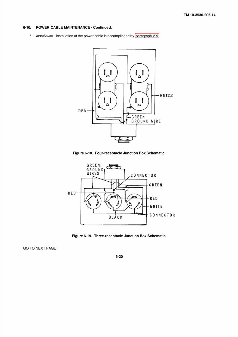
8/7/2019 TM 10-3530-205-10 CLOTHING REPAIR SHOP
http://slidepdf.com/reader/full/tm-10-3530-205-10-clothing-repair-shop 242/455
TM 10-3530-205-14
6-10. POWER CABLE MAINTENANCE - Continued.
f. Installation. Installation of the power cable is accomplished by paragraph 2-9.
Figure 6-18. Four-receptacle Junction Box Schematic.
Figure 6-19. Three-receptacle Junction Box Schematic.
GO TO NEXT PAGE
6-20
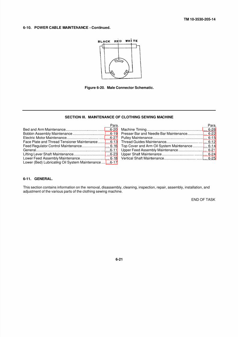
8/7/2019 TM 10-3530-205-10 CLOTHING REPAIR SHOP
http://slidepdf.com/reader/full/tm-10-3530-205-10-clothing-repair-shop 243/455
TM 10-3530-205-14
6-10. POWER CABLE MAINTENANCE - Continued.
Figure 6-20. Male Connector Schematic.
SECTION III. MAINTENANCE OF CLOTHING SEWING MACHINE
Para. Para.Bed and Arm Maintenance................................ ...... .....6-20Bobbin Assembly Maintenance ................................ ....6-19Electric Motor Maintenance................................ ..... .....6-27Face Plate and Thread Tensioner Maintenance ....... ....6-13Feed Regulator Control Maintenance....................... .... 6-16General................................ ................................ .... ....6-11Lifting Lever Shaft Maintenance................................ ...6-23Lower Feed Assembly Maintenance......................... .... 6-18
Lower (Bed) Lubricating Oil System Maintenance .... ....6-17
Machine Timing................................ ....................... .... 6-26Presser Bar and Needle Bar Maintenance................ ... 6-22Pulley Maintenance................................ .................. ... 6-15Thread Guides Maintenance................................ .... .... 6-12Top Cover and Arm Oil System Maintenance ........... ... 6-14Upper Feed Assembly Maintenance......................... ... 6-21Upper Shaft Maintenance................................ ........ .... 6-24Vertical Shaft Maintenance................................ ...... .... 6-25
6-11. G ENERAL.
This section contains information on the removal, disassembly, cleaning, inspection, repair, assembly, installation, andadjustment of the various parts of the clothing sewing machine.
END OF TASK
6-21
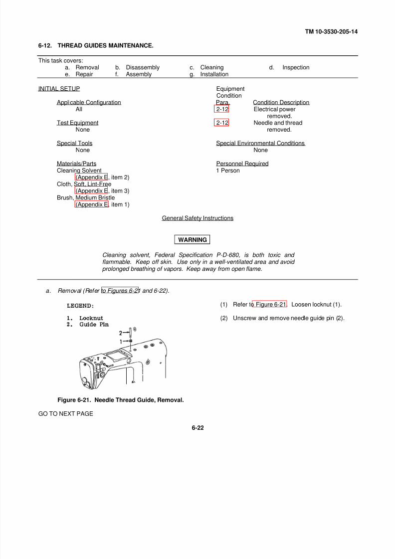
8/7/2019 TM 10-3530-205-10 CLOTHING REPAIR SHOP
http://slidepdf.com/reader/full/tm-10-3530-205-10-clothing-repair-shop 244/455
TM 10-3530-205-14
6-12. T HREAD GUIDES MAINTENANCE.
This task covers:a. Removal b. Disassembly c. Cleaning d. Inspectione. Repair f. Assembly g. Installation
INITIAL SETUP EquipmentConditionApplicable Configuration Para. Condition Description
All 2-12 Electrical powerremoved.
Test Equipment 2-12 Needle and threadNone removed.
Special Tools Special Environmental ConditionsNone None
Materials/Parts Personnel RequiredCleaning Solvent 1 Person
(Appendix E , item 2)Cloth, Soft, Lint-Free(Appendix E , item 3)
Brush, Medium Bristle(Appendix E, item 1)
General Safety Instructions
WARNING
Cleaning solvent, Federal Specification P-D-680, is both toxic and flammable. Keep off skin. Use only in a well-ventilated area and avoid
prolonged breathing of vapors. Keep away from open flame.
a. Removal (Refer t o Figures 6-21 and 6-22).
(1) Refer to Figure 6-21. Loosen locknut (1).
(2) Unscrew and remove needle guide pin (2).
Figure 6-21. Needle Thread Guide, Removal.
GO TO NEXT PAGE
6-22
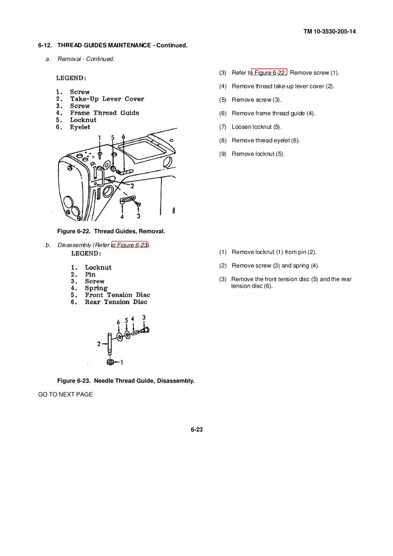
8/7/2019 TM 10-3530-205-10 CLOTHING REPAIR SHOP
http://slidepdf.com/reader/full/tm-10-3530-205-10-clothing-repair-shop 245/455
TM 10-3530-205-14
6-12. THREAD GUIDES MAINTENANCE - Continued.
a. Removal - Continued.
(3) Refer to Figure 6-22. Remove screw (1).
(4) Remove thread take-up lever cover (2).
(5) Remove screw (3).
(6) Remove frame thread guide (4).
(7) Loosen locknut (5).
(8) Remove thread eyelet (6).
(9) Remove locknut (5).
Figure 6-22. Thread Guides, Removal.
b. Disassembly (Refer t o Figure 6-23) .(1) Remove locknut (1) from pin (2).
(2) Remove screw (3) and spring (4).
(3) Remove the front tension disc (5) and the reartension disc (6).
Figure 6-23. Needle Thread Guide, Disassembly.
GO TO NEXT PAGE
6-23
8/7/2019 TM 10-3530-205-10 CLOTHING REPAIR SHOP
http://slidepdf.com/reader/full/tm-10-3530-205-10-clothing-repair-shop 246/455
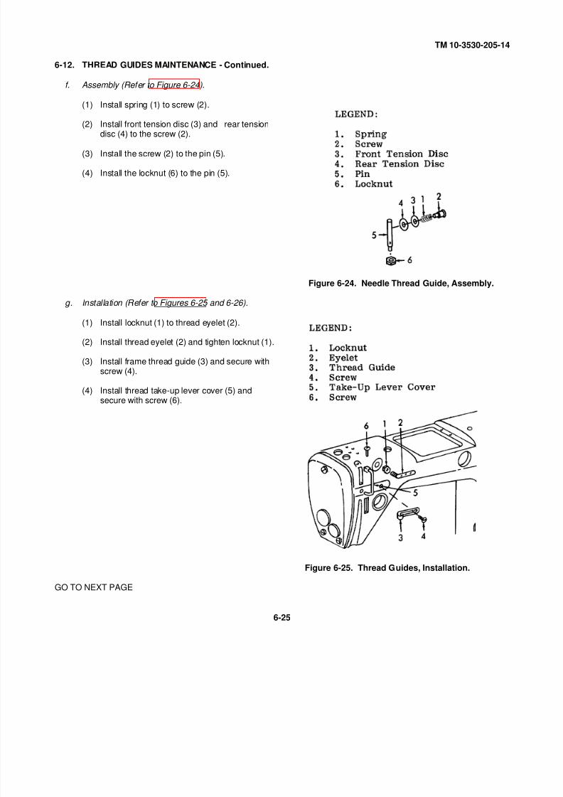
8/7/2019 TM 10-3530-205-10 CLOTHING REPAIR SHOP
http://slidepdf.com/reader/full/tm-10-3530-205-10-clothing-repair-shop 247/455
TM 10-3530-205-14
6-12. THREAD GUIDES MAINTENANCE - Continued.
f. Assembly (Refer t o Figure 6-24) .
(1) Install spring (1) to screw (2).
(2) Install front tension disc (3) and rear tensiondisc (4) to the screw (2).
(3) Install the screw (2) to the pin (5).
(4) Install the locknut (6) to the pin (5).
Figure 6-24. Needle Thread Guide, Assembly.
g. Installation (Refer t o Figures 6-25 and 6-26).
(1) Install locknut (1) to thread eyelet (2).
(2) Install thread eyelet (2) and tighten locknut (1).
(3) Install frame thread guide (3) and secure withscrew (4).
(4) Install thread take-up lever cover (5) andsecure with screw (6).
Figure 6-25. Thread Guides, Installation.
GO TO NEXT PAGE
6-25
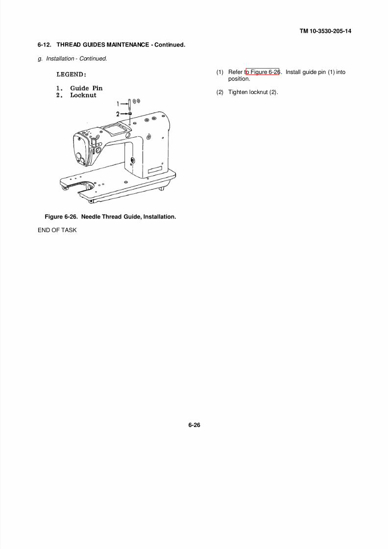
8/7/2019 TM 10-3530-205-10 CLOTHING REPAIR SHOP
http://slidepdf.com/reader/full/tm-10-3530-205-10-clothing-repair-shop 248/455
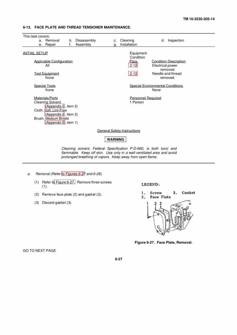
8/7/2019 TM 10-3530-205-10 CLOTHING REPAIR SHOP
http://slidepdf.com/reader/full/tm-10-3530-205-10-clothing-repair-shop 249/455
TM 10-3530-205-14
6-13. F ACE PLATE AND THREAD TENSIONER MAINTENANCE.
This task covers:a. Removal b. Disassembly c. Cleaning d. Inspectione. Repair f. Assembly g. Installation
INITIAL SETUP EquipmentConditionApplicable Configuration Para. Condition Description
All 2-12 Electrical powerremoved.
Test Equipment 2-12 Needle and threadNone removed.
Special Tools Special Environmental ConditionsNone None
Materials/Parts Personnel RequiredCleaning Solvent 1 Person
(Appendix E , item 2)Cloth, Soft, Lint-Free(Appendix E , item 3)
Brush, Medium Bristle(Appendix E, item 1)
General Safety Instructions
WARNING
Cleaning solvent, Federal Specification P-D-680, is both toxic and flammable. Keep off skin. Use only in a well-ventilated area and avoid prolonged breathing of vapors. Keep away from open flame.
a. Removal (Refer to Figures 6-27 and 6-28).
(1) Refer to Figure 6-27. Remove three screws(1).
(2) Remove face plate (2) and gasket (3).
(3) Discard gasket (3).
Figure 6-27. Face Plate, Removal.
GO TO NEXT PAGE
6-27
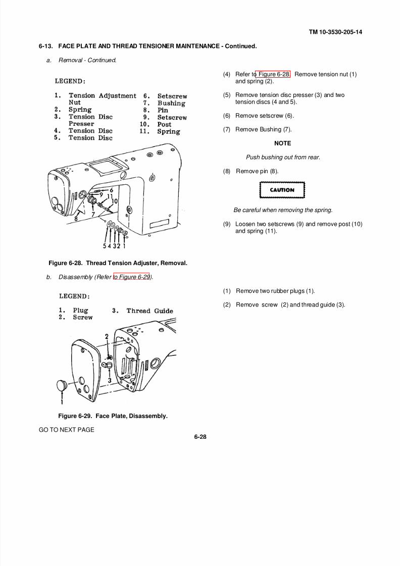
8/7/2019 TM 10-3530-205-10 CLOTHING REPAIR SHOP
http://slidepdf.com/reader/full/tm-10-3530-205-10-clothing-repair-shop 250/455
TM 10-3530-205-14
6-13. FACE PLATE AND THREAD TENSIONER MAINTENANCE - Continued.
a. Removal - Continued.
Figure 6-28. Thread Tension Adjuster, Removal.
(4) Refer to Figure 6-28. Remove tension nut (1)and spring (2).
(5) Remove tension disc presser (3) and twotension discs (4 and 5).
(6) Remove setscrew (6).
(7) Remove Bushing (7).
NOTE
Push bushing out from rear.
(8) Remove pin (8).
Be careful when removing the spring.
(9) Loosen two setscrews (9) and remove post (10)and spring (11).
b. Disassembly (Refer t o Figure 6-29) .
(1) Remove two rubber plugs (1).
(2) Remove screw (2) and thread guide (3).
Figure 6-29. Face Plate, Disassembly.
GO TO NEXT PAGE6-28
8/7/2019 TM 10-3530-205-10 CLOTHING REPAIR SHOP
http://slidepdf.com/reader/full/tm-10-3530-205-10-clothing-repair-shop 251/455
TM 10-3530-205-14
6-13. FACE PLATE AND THREAD TENSIONER MAINTENANCE - Continued.
c. Cleaning.
(1) Remove all buildups of grease, dirt, etc. by wiping with a soft, clean cloth.
WARNING
Cleaning solvent, Federal Specification P-D-680, is both toxic andflammable. Keep off skin. Use only in a well-ventilated area and avoidprolonged breathing of vapors. Keep away from open flame.
(2) Clean using cleaning solven t (Appendix E, item 2) and either a soft, clean cloth (Appendix E , item 3) or amedium bristle brush (Appendix E, item 1).
(3) Allow to dry.
d. Inspection.
(1) Inspect hardware for damage.
(2) Inspect the springs for damage.
(3) Inspect the pin for damage.
(4) Inspect the bushing for damage.
(5) Inspect the disc presser for damage.
(6) Inspect the tension discs for damage.
(7) Inspect the post for damage.
(8) Inspect face plate for damage.
(9) Inspect thread guide for damage.
(10) Inspect the rubber plugs for deterioration and damage.
e. Repair. Repair of the face plate and thread tensioner is limited to the replacement of defective components.
GO TO NEXT PAGE
6-29
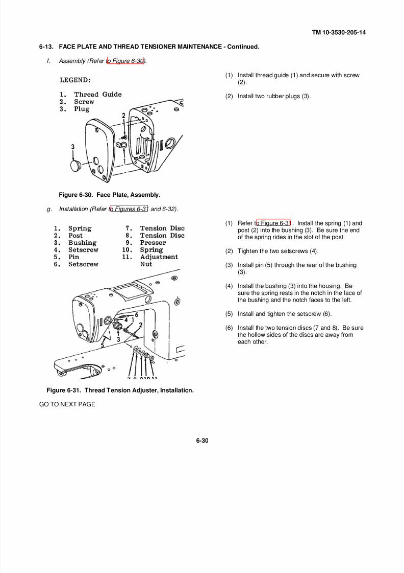
8/7/2019 TM 10-3530-205-10 CLOTHING REPAIR SHOP
http://slidepdf.com/reader/full/tm-10-3530-205-10-clothing-repair-shop 252/455
TM 10-3530-205-14
6-13. FACE PLATE AND THREAD TENSIONER MAINTENANCE - Continued.
f. Assembly (Refer t o Figure 6-30) .
(1) Install thread guide (1) and secure with screw(2).
(2) Install two rubber plugs (3).
Figure 6-30. Face Plate, Assembly.
g. Installation (Refer t o Figures 6-31 and 6-32).
(1) Refer t o Figure 6-31 . Install the spring (1) andpost (2) into the bushing (3). Be sure the endof the spring rides in the slot of the post.
(2) Tighten the two setscrews (4).
(3) Install pin (5) through the rear of the bushing(3).
(4) Install the bushing (3) into the housing. Besure the spring rests in the notch in the face ofthe bushing and the notch faces to the left.
(5) Install and tighten the setscrew (6).
(6) Install the two tension discs (7 and 8). Be surethe hollow sides of the discs are away fromeach other.
Figure 6-31. Thread Tension Adjuster, Installation.
GO TO NEXT PAGE
6-30
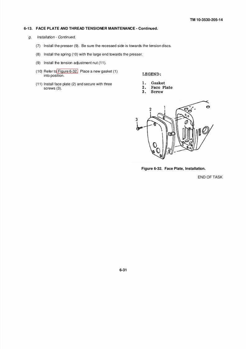
8/7/2019 TM 10-3530-205-10 CLOTHING REPAIR SHOP
http://slidepdf.com/reader/full/tm-10-3530-205-10-clothing-repair-shop 253/455
TM 10-3530-205-14
6-13. FACE PLATE AND THREAD TENSIONER MAINTENANCE - Continued.
g. Installation - Continued.
(7) Install the presser (9). Be sure the recessed side is towards the tension discs.
(8) Install the spring (10) with the large end towards the presser.(9) Install the tension adjustment nut (11).
(10) Refer to Figure 6-32. Place a new gasket (1)into position.
(11) Install face plate (2) and secure with threescrews (3).
Figure 6-32. Face Plate, Installation.
END OF TASK
6-31
8/7/2019 TM 10-3530-205-10 CLOTHING REPAIR SHOP
http://slidepdf.com/reader/full/tm-10-3530-205-10-clothing-repair-shop 254/455
TM 10-3530-205-14
6-14. T OP COVER AND ARM OIL SYSTEM MAINTENANCE.
This task covers:a. Removal b. Cleaning c. Inspection d. Repaire. Installation
INITIAL SETUP EquipmentConditionApplicable Configuration Para. Condition Description
All 2-12 Electrical powerremoved.
Test Equipment 2-12 Needle and threadNone removed.
Special Tools Special Environmental ConditionsNone None
Materials/Parts Personnel RequiredCleaning Solvent 1 Person
(Appendix E , item 2)Cloth, Soft, Lint-Free(Appendix E , item 3)
Brush, Medium Bristle(Appendix E, item 1)
Gasket, CoverGasket, Oil Line (2 required)
General Safety Instructions
WARNING
Cleaning solvent, Federal Specification P-D-680, is both toxic and
flammable. Keep off skin. Use only in a well-ventilated area and avoid prolonged breathing of vapors. Keep away from open flame.
GO TO NEXT PAGE
6-32
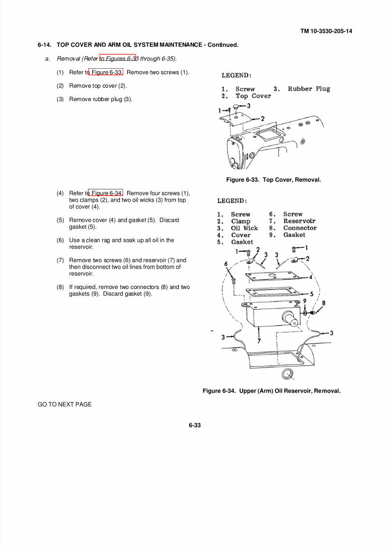
8/7/2019 TM 10-3530-205-10 CLOTHING REPAIR SHOP
http://slidepdf.com/reader/full/tm-10-3530-205-10-clothing-repair-shop 255/455
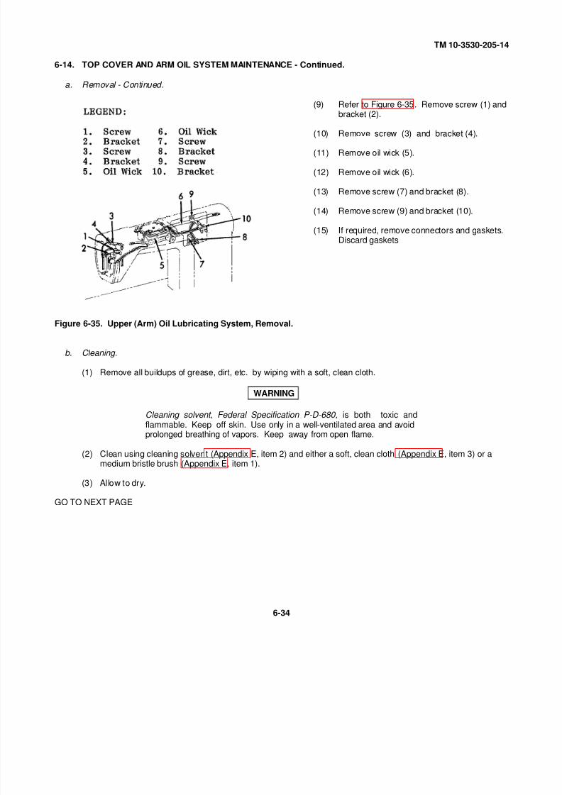
8/7/2019 TM 10-3530-205-10 CLOTHING REPAIR SHOP
http://slidepdf.com/reader/full/tm-10-3530-205-10-clothing-repair-shop 256/455
TM 10-3530-205-14
6-14. TOP COVER AND ARM OIL SYSTEM MAINTENANCE - Continued.
a. Removal - Continued.
(9) Refer to Figure 6-35 . Remove screw (1) andbracket (2).
(10) Remove screw (3) and bracket (4).
(11) Remove oil wick (5).
(12) Remove oil wick (6).
(13) Remove screw (7) and bracket (8).
(14) Remove screw (9) and bracket (10).
(15) If required, remove connectors and gaskets.Discard gaskets
Figure 6-35. Upper (Arm) Oil Lubricating System, Removal.
b. Cleaning.
(1) Remove all buildups of grease, dirt, etc. by wiping with a soft, clean cloth.
WARNING
Cleaning solvent, Federal Specification P-D-680, is both toxic andflammable. Keep off skin. Use only in a well-ventilated area and avoidprolonged breathing of vapors. Keep away from open flame.
(2) Clean using cleaning solven t (Appendix E, item 2) and either a soft, clean cloth (Appendix E , item 3) or amedium bristle brush (Appendix E, item 1).
(3) Allow to dry.
GO TO NEXT PAGE
6-34
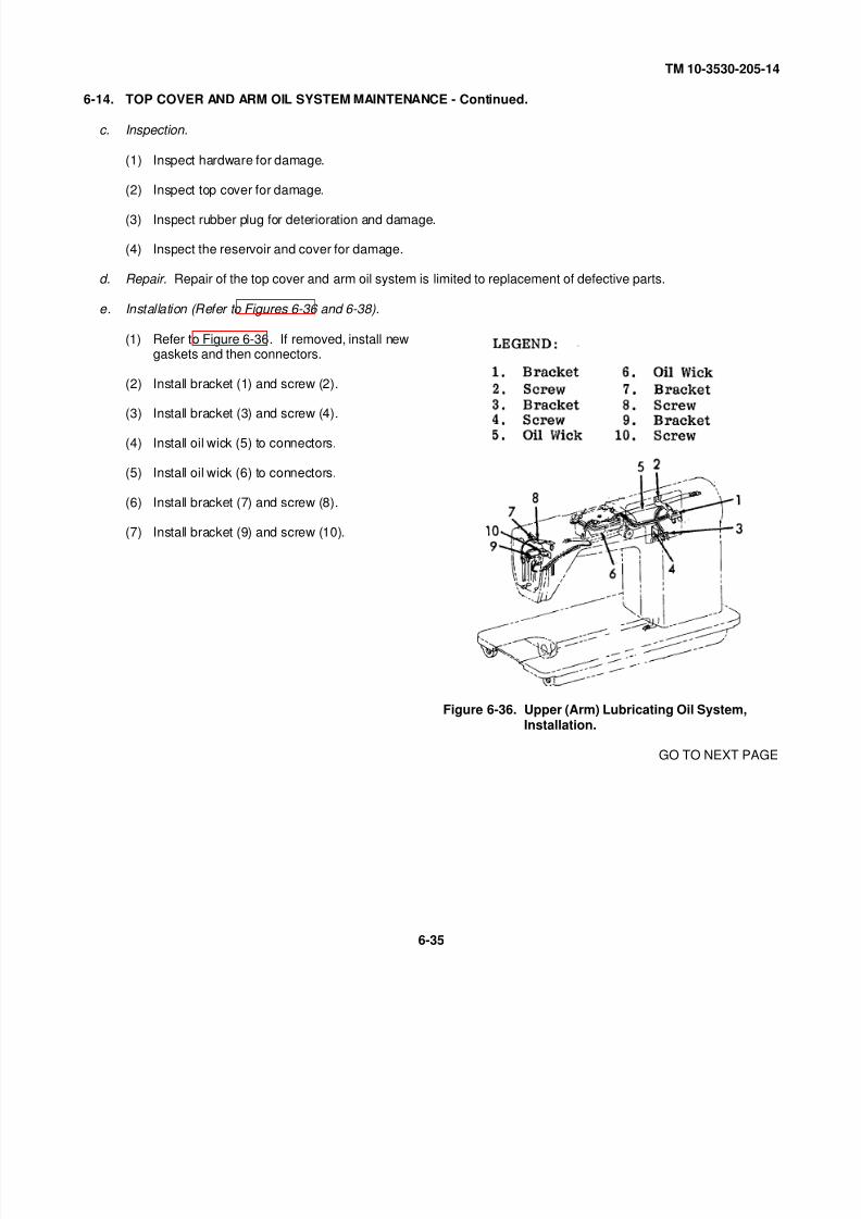
8/7/2019 TM 10-3530-205-10 CLOTHING REPAIR SHOP
http://slidepdf.com/reader/full/tm-10-3530-205-10-clothing-repair-shop 257/455
TM 10-3530-205-14
6-14. TOP COVER AND ARM OIL SYSTEM MAINTENANCE - Continued.
c. Inspection.
(1) Inspect hardware for damage.
(2) Inspect top cover for damage.(3) Inspect rubber plug for deterioration and damage.
(4) Inspect the reservoir and cover for damage.
d. Repair. Repair of the top cover and arm oil system is limited to replacement of defective parts.
e. Installation (Refer t o Figures 6-36 and 6-38).
(1) Refer t o Figure 6-36 . If removed, install newgaskets and then connectors.
(2) Install bracket (1) and screw (2).
(3) Install bracket (3) and screw (4).
(4) Install oil wick (5) to connectors.
(5) Install oil wick (6) to connectors.
(6) Install bracket (7) and screw (8).
(7) Install bracket (9) and screw (10).
Figure 6-36. Upper (Arm) Lubricating Oil System,Installation.
GO TO NEXT PAGE
6-35
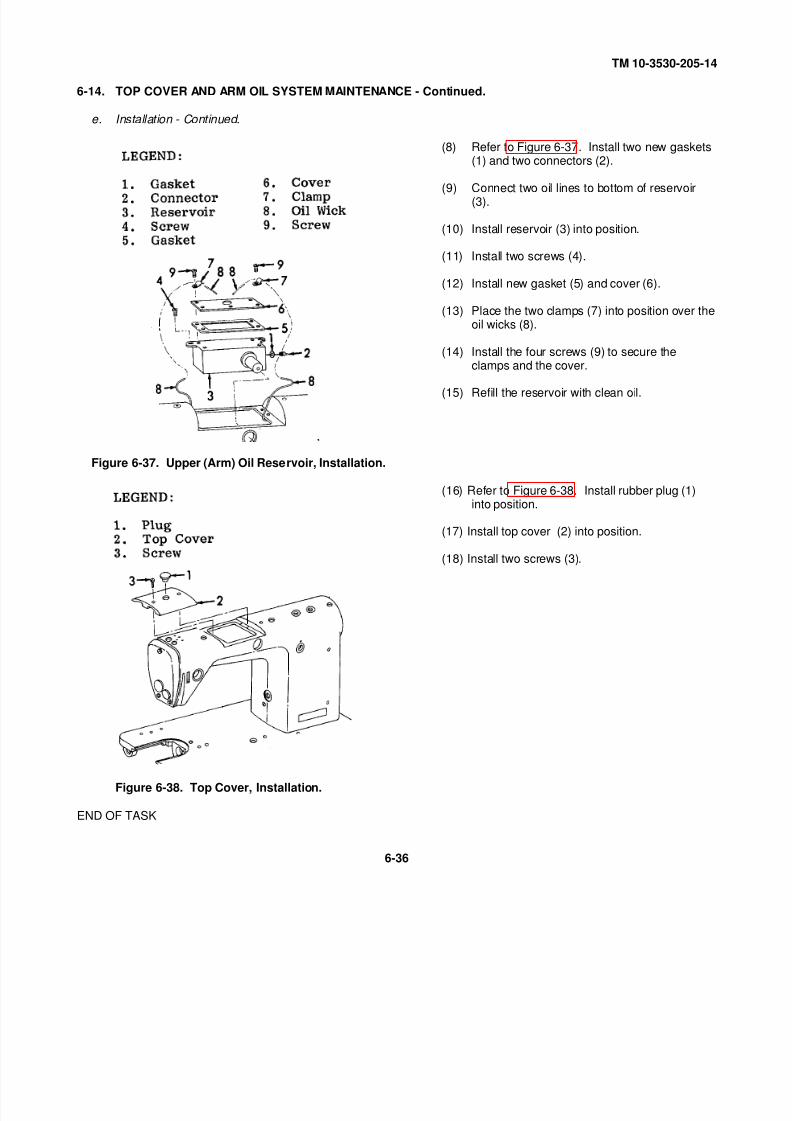
8/7/2019 TM 10-3530-205-10 CLOTHING REPAIR SHOP
http://slidepdf.com/reader/full/tm-10-3530-205-10-clothing-repair-shop 258/455
TM 10-3530-205-14
6-14. TOP COVER AND ARM OIL SYSTEM MAINTENANCE - Continued.
e. Installation - Continued.
(8) Refer t o Figure 6-37 . Install two new gaskets(1) and two connectors (2).
(9) Connect two oil lines to bottom of reservoir(3).
(10) Install reservoir (3) into position.
(11) Install two screws (4).
(12) Install new gasket (5) and cover (6).
(13) Place the two clamps (7) into position over theoil wicks (8).
(14) Install the four screws (9) to secure theclamps and the cover.
(15) Refill the reservoir with clean oil.
Figure 6-37. Upper (Arm) Oil Reservoir, Installation.
(16) Refer to Figure 6-38. Install rubber plug (1)into position.
(17) Install top cover (2) into position.
(18) Install two screws (3).
Figure 6-38. Top Cover, Installation.
END OF TASK
6-36
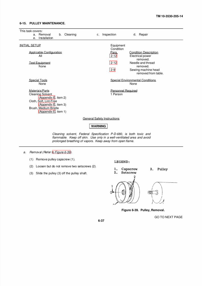
8/7/2019 TM 10-3530-205-10 CLOTHING REPAIR SHOP
http://slidepdf.com/reader/full/tm-10-3530-205-10-clothing-repair-shop 259/455
TM 10-3530-205-14
6-15. P ULLEY MAINTENANCE.
This task covers:a. Removal b. Cleaning c. Inspection d. Repaire. Installation
INITIAL SETUP EquipmentConditionApplicable Configuration Para. Condition Description
All 2-12 Electrical powerremoved.
Test Equipment 2-12 Needle and threadNone removed.
2-9 Sewing machine headremoved from table.
Special Tools Special Environmental ConditionsNone None
Materials/Parts Personnel RequiredCleaning Solvent 1 Person(Appendix E , item 2)
Cloth, Soft, Lint-Free(Appendix E , item 3)
Brush, Medium Bristle(Appendix E, item 1)
General Safety Instructions
WARNING
Cleaning solvent, Federal Specification P-D-680, is both toxic and
flammable. Keep off skin. Use only in a well-ventilated area and avoid prolonged breathing of vapors. Keep away from open flame.
a. Removal (Refer t o Figure 6-39) .
(1) Remove pulley capscrew (1).
(2) Loosen but do not remove two setscrews (2).
(3) Slide the pulley (3) off the pulley shaft.
Figure 6-39. Pulley, Removal.
GO TO NEXT PAGE6-37
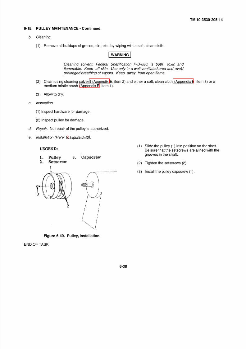
8/7/2019 TM 10-3530-205-10 CLOTHING REPAIR SHOP
http://slidepdf.com/reader/full/tm-10-3530-205-10-clothing-repair-shop 260/455
TM 10-3530-205-14
6-15. PULLEY MAINTENANCE - Continued.
b. Cleaning.
(1) Remove all buildups of grease, dirt, etc. by wiping with a soft, clean cloth.
WARNING
Cleaning solvent, Federal Specification P-D-680, is both toxic and flammable. Keep off skin. Use only in a well-ventilated area and avoid prolonged breathing of vapors. Keep away from open flame.
(2) Clean using cleaning solven t (Appendix E, item 2) and either a soft, clean cloth (Appendix E , item 3) or amedium bristle brush (Appendix E, item 1).
(3) Allow to dry.
c. Inspection.
(1) Inspect hardware for damage.
(2) Inspect pulley for damage.
d. Repair. No repair of the pulley is authorized.
e. Installation (Refer to Figure 6-40) .
(1) Slide the pulley (1) into position on the shaft.Be sure that the setscrews are alined with thegrooves in the shaft.
(2) Tighten the setscrews (2).
(3) Install the pulley capscrew (1).
Figure 6-40. Pulley, Installation.
END OF TASK
6-38
8/7/2019 TM 10-3530-205-10 CLOTHING REPAIR SHOP
http://slidepdf.com/reader/full/tm-10-3530-205-10-clothing-repair-shop 261/455
TM 10-3530-205-14
6-16. F EED REGULATOR CONTROL MAINTENANCE.
This task covers:a. Removal b. Cleaning c. Inspection d. Repaire. Installation
INITIAL SETUP EquipmentConditionApplicable Configuration Para. Condition Description
All 2-12 Electrical powerremoved.
Test Equipment 2-12 Needle and threadNone removed.
Special Tools Special Environmental ConditionsNone None
Materials/Parts Personnel RequiredCleaning Solvent 1 Person
(Appendix E , item 2)Cloth, Soft, Lint-Free(Appendix E , item 3)
Brush, Medium Bristle(Appendix E, item 1)
Packing, Preformed (2 required)
General Safety Instructions
WARNING
Cleaning solvent, Federal Specification P-D-680, is both toxic and flammable. Keep off skin. Use only in a well-ventilated area and avoid
prolonged breathing of vapors. Keep away from open flame.
GO TO NEXT PAGE
6-39
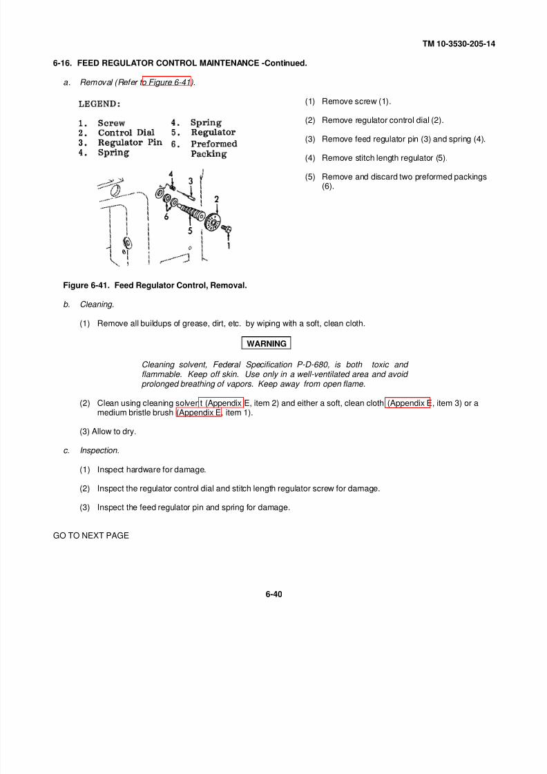
8/7/2019 TM 10-3530-205-10 CLOTHING REPAIR SHOP
http://slidepdf.com/reader/full/tm-10-3530-205-10-clothing-repair-shop 262/455
TM 10-3530-205-14
6-16. FEED REGULATOR CONTROL MAINTENANCE -Continued.
a. Removal (Refer t o Figure 6-41) .
(1) Remove screw (1).
(2) Remove regulator control dial (2).
(3) Remove feed regulator pin (3) and spring (4).
(4) Remove stitch length regulator (5).
(5) Remove and discard two preformed packings(6).
Figure 6-41. Feed Regulator Control, Removal.
b. Cleaning.
(1) Remove all buildups of grease, dirt, etc. by wiping with a soft, clean cloth.
WARNING
Cleaning solvent, Federal Specification P-D-680, is both toxic and
flammable. Keep off skin. Use only in a well-ventilated area and avoid prolonged breathing of vapors. Keep away from open flame.
(2) Clean using cleaning solven t (Appendix E, item 2) and either a soft, clean cloth (Appendix E , item 3) or amedium bristle brush (Appendix E, item 1).
(3) Allow to dry.
c. Inspection.
(1) Inspect hardware for damage.
(2) Inspect the regulator control dial and stitch length regulator screw for damage.
(3) Inspect the feed regulator pin and spring for damage.
GO TO NEXT PAGE
6-40
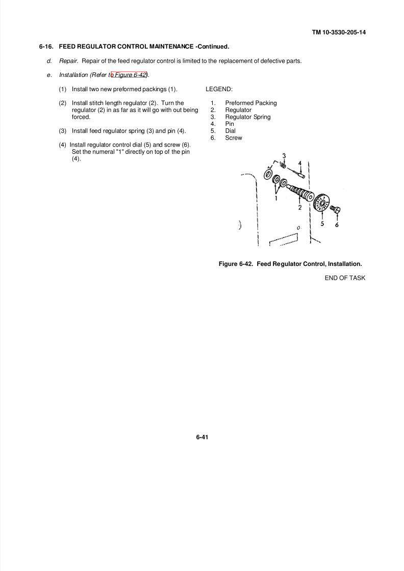
8/7/2019 TM 10-3530-205-10 CLOTHING REPAIR SHOP
http://slidepdf.com/reader/full/tm-10-3530-205-10-clothing-repair-shop 263/455
TM 10-3530-205-14
6-16. FEED REGULATOR CONTROL MAINTENANCE -Continued.
d. Repair. Repair of the feed regulator control is limited to the replacement of defective parts.
e. Installation (Refer to Figure 6-42) .
(1) Install two new preformed packings (1).(2) Install stitch length regulator (2). Turn the
regulator (2) in as far as it will go with out beingforced.
(3) Install feed regulator spring (3) and pin (4).
(4) Install regulator control dial (5) and screw (6).Set the numeral "1" directly on top of the pin(4).
LEGEND:1. Preformed Packing2. Regulator3. Regulator Spring4. Pin5. Dial6. Screw
Figure 6-42. Feed Regulator Control, Installation.
END OF TASK
6-41
8/7/2019 TM 10-3530-205-10 CLOTHING REPAIR SHOP
http://slidepdf.com/reader/full/tm-10-3530-205-10-clothing-repair-shop 264/455
TM 10-3530-205-14
6-17. L OWER (BED) LUBRICATING OIL SYSTEM MAINTENANCE.
This task covers:a. Removal b. Cleaning c. Inspection d. Repaire. Installation
INITIAL SETUP EquipmentConditionApplicable Configuration Para. Condition Description
All 2-12 Electrical powerremoved.
Test Equipment 2-12 Needle and threadNone removed.
2-9 Sewing machine removedSpecial Tools from table.
NoneSpecial Environmental Conditions
Materials/Parts NoneCleaning Solvent
(Appendix E , item 2) Personnel RequiredCloth, Soft, Lint-Free 1 Person(Appendix E , item 3)
Brush, Medium Bristle(Appendix E, item 1)
Gasket, Oil Line (4 required)Gasket Cover
General Safety Instructions
WARNING
Cleaning solvent, Federal Specification P-D-680, is both toxic and
flammable. Keep off skin. Use only in a well-ventilated area and avoid prolonged breathing of vapors. Keep away from open flame.
GO TO NEXT PAGE
6-42
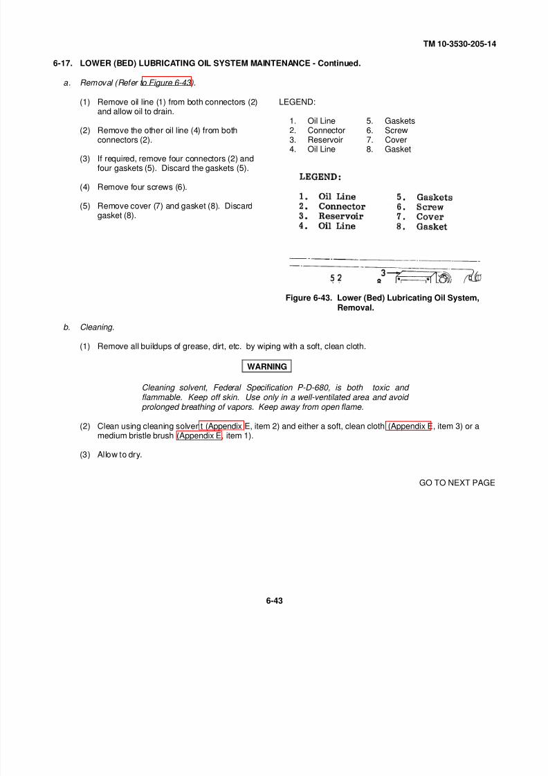
8/7/2019 TM 10-3530-205-10 CLOTHING REPAIR SHOP
http://slidepdf.com/reader/full/tm-10-3530-205-10-clothing-repair-shop 265/455
TM 10-3530-205-14
6-17. LOWER (BED) LUBRICATING OIL SYSTEM MAINTENANCE - Continued.
a. Removal (Refer t o Figure 6-43) .
(1) Remove oil line (1) from both connectors (2)and allow oil to drain.
(2) Remove the other oil line (4) from bothconnectors (2).
(3) If required, remove four connectors (2) andfour gaskets (5). Discard the gaskets (5).
(4) Remove four screws (6).
(5) Remove cover (7) and gasket (8). Discardgasket (8).
LEGEND:
1. Oil Line 5. Gaskets2. Connector 6. Screw3. Reservoir 7. Cover4. Oil Line 8. Gasket
Figure 6-43. Lower (Bed) Lubricating Oil System,Removal.
b. Cleaning.
(1) Remove all buildups of grease, dirt, etc. by wiping with a soft, clean cloth.
WARNING
Cleaning solvent, Federal Specification P-D-680, is both toxic and flammable. Keep off skin. Use only in a well-ventilated area and avoid prolonged breathing of vapors. Keep away from open flame.
(2) Clean using cleaning solven t (Appendix E, item 2) and either a soft, clean cloth (Appendix E , item 3) or amedium bristle brush (Appendix E, item 1).
(3) Allow to dry.
GO TO NEXT PAGE
6-43
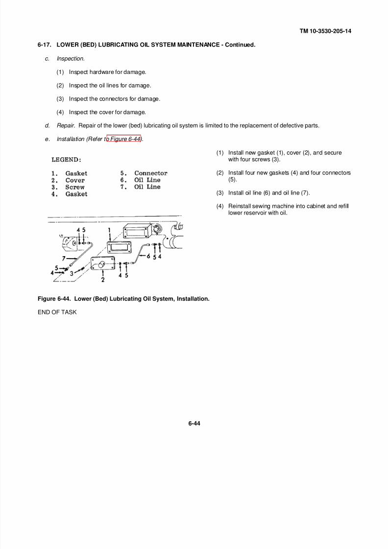
8/7/2019 TM 10-3530-205-10 CLOTHING REPAIR SHOP
http://slidepdf.com/reader/full/tm-10-3530-205-10-clothing-repair-shop 266/455
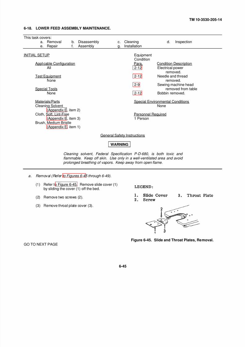
8/7/2019 TM 10-3530-205-10 CLOTHING REPAIR SHOP
http://slidepdf.com/reader/full/tm-10-3530-205-10-clothing-repair-shop 267/455
TM 10-3530-205-14
6-18. L OWER FEED ASSEMBLY MAINTENANCE.
This task covers:a. Removal b. Disassembly c. Cleaning d. Inspectione. Repair f. Assembly g. Installation
INITIAL SETUP EquipmentConditionApplicable Configuration Para. Condition Description
All 2-12 Electrical powerremoved.
Test Equipment 2-12 Needle and threadNone removed.
2-9 Sewing machine headSpecial Tools removed from table
None 2-12 Bobbin removed.
Materials/Parts Special Environmental ConditionsCleaning Solvent None
(Appendix E , item 2)Cloth, Soft, Lint-Free Personnel Required(Appendix E , item 3) 1 Person
Brush, Medium Bristle(Appendix E, item 1)
General Safety Instructions
WARNING
Cleaning solvent, Federal Specification P-D-680, is both toxic and flammable. Keep off skin. Use only in a well-ventilated area and avoid prolonged breathing of vapors. Keep away from open flame.
a. Removal (Refer t o Figures 6-45 through 6-49).
(1) Refer t o Figure 6-45. Remove slide cover (1)by sliding the cover (1) off the bed.
(2) Remove two screws (2).
(3) Remove throat plate cover (3).
Figure 6-45. Slide and Throat Plates, Removal.GO TO NEXT PAGE
6-45
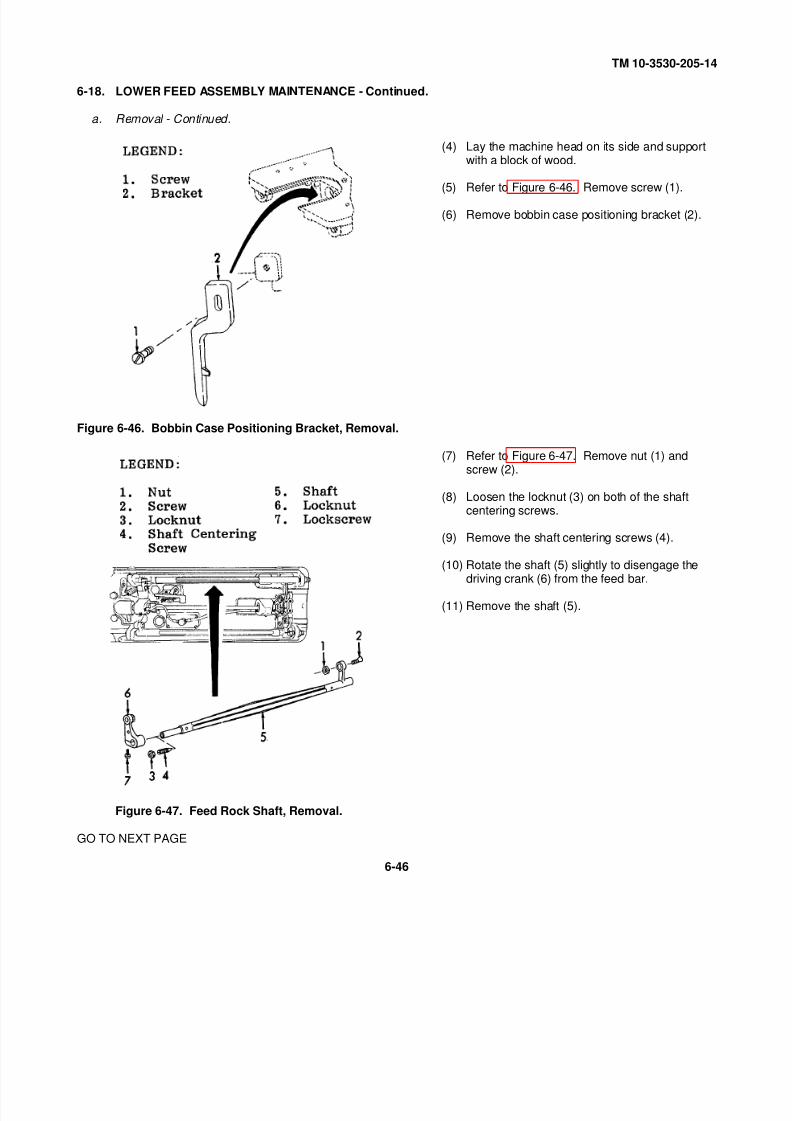
8/7/2019 TM 10-3530-205-10 CLOTHING REPAIR SHOP
http://slidepdf.com/reader/full/tm-10-3530-205-10-clothing-repair-shop 268/455
TM 10-3530-205-14
6-18. LOWER FEED ASSEMBLY MAINTENANCE - Continued.
a. Removal - Continued.
(4) Lay the machine head on its side and supportwith a block of wood.
(5) Refer to Figure 6-46. Remove screw (1).
(6) Remove bobbin case positioning bracket (2).
Figure 6-46. Bobbin Case Positioning Bracket, Removal.
(7) Refer to Figure 6-47. Remove nut (1) andscrew (2).
(8) Loosen the locknut (3) on both of the shaftcentering screws.
(9) Remove the shaft centering screws (4).(10) Rotate the shaft (5) slightly to disengage the
driving crank (6) from the feed bar.
(11) Remove the shaft (5).
Figure 6-47. Feed Rock Shaft, Removal.
GO TO NEXT PAGE
6-46
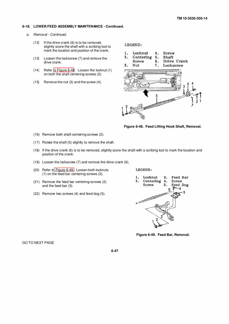
8/7/2019 TM 10-3530-205-10 CLOTHING REPAIR SHOP
http://slidepdf.com/reader/full/tm-10-3530-205-10-clothing-repair-shop 269/455
TM 10-3530-205-14
6-18. LOWER FEED ASSEMBLY MAINTENANCE - Continued.
a. Removal - Continued.
(12) If the drive crank (6) is to be removed,slightly score the shaft with a scribing tool to
mark the location and position of the crank.(13) Loosen the lockscrew (7) and remove the
drive crank.
(14) Refer t o Figure 6-48 . Loosen the locknut (1)on both the shaft centering screws (2).
(15) Remove the nut (3) and the screw (4).
Figure 6-48. Feed Lifting Hook Shaft, Removal.
(16) Remove both shaft centering screws (2).
(17) Rotate the shaft (5) slightly to remove the shaft.
(18) If the drive crank (6) is to be removed, slightly score the shaft with a scribing tool to mark the location andposition of the crank.
(19) Loosen the lockscrew (7) and remove the drive crank (6).
(20) Refer to Figure 6-49. Loosen both locknuts(1) on the feed bar centering screws (2).
(21) Remove the feed bar centering screws (2)and the feed bar (3).
(22) Remove two screws (4) and feed dog (5).
Figure 6-49. Feed Bar, Removal.
GO TO NEXT PAGE
6-47
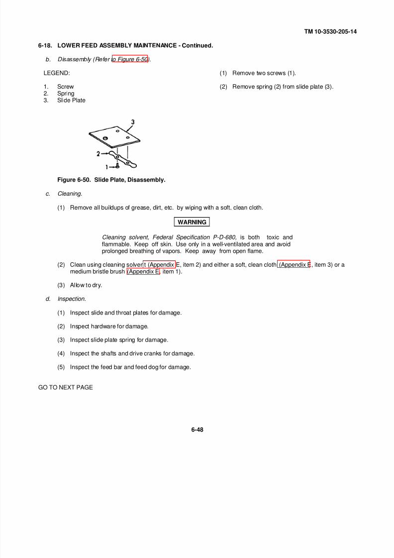
8/7/2019 TM 10-3530-205-10 CLOTHING REPAIR SHOP
http://slidepdf.com/reader/full/tm-10-3530-205-10-clothing-repair-shop 270/455
TM 10-3530-205-14
6-18. LOWER FEED ASSEMBLY MAINTENANCE - Continued.
b. Disassembly (Refer t o Figure 6-50) .
LEGEND:
1. Screw2. Spring3. Slide Plate
(1) Remove two screws (1).
(2) Remove spring (2) from slide plate (3).
Figure 6-50. Slide Plate, Disassembly.
c. Cleaning.
(1) Remove all buildups of grease, dirt, etc. by wiping with a soft, clean cloth.
WARNING
Cleaning solvent, Federal Specification P-D-680, is both toxic andflammable. Keep off skin. Use only in a well-ventilated area and avoidprolonged breathing of vapors. Keep away from open flame.
(2) Clean using cleaning solven t (Appendix E, item 2) and either a soft, clean cloth (Appendix E , item 3) or amedium bristle brush (Appendix E, item 1).
(3) Allow to dry.
d. Inspection.
(1) Inspect slide and throat plates for damage.
(2) Inspect hardware for damage.
(3) Inspect slide plate spring for damage.
(4) Inspect the shafts and drive cranks for damage.
(5) Inspect the feed bar and feed dog for damage.
GO TO NEXT PAGE
6-48
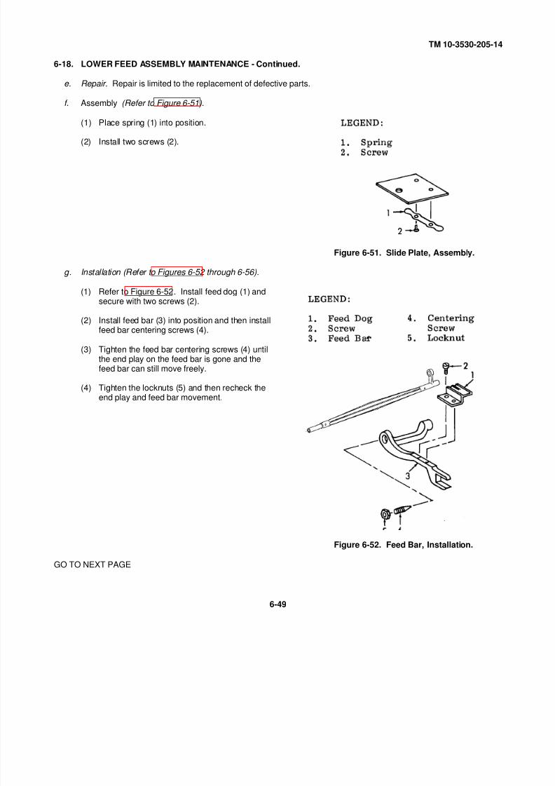
8/7/2019 TM 10-3530-205-10 CLOTHING REPAIR SHOP
http://slidepdf.com/reader/full/tm-10-3530-205-10-clothing-repair-shop 271/455
TM 10-3530-205-14
6-18. LOWER FEED ASSEMBLY MAINTENANCE - Continued.
e. Repair. Repair is limited to the replacement of defective parts.
f. Assembly (Refer to Figure 6-51) .
(1) Place spring (1) into position.(2) Install two screws (2).
Figure 6-51. Slide Plate, Assembly.
g. Installation (Refer t o Figures 6-52 through 6-56).
(1) Refer t o Figure 6-52 . Install feed dog (1) andsecure with two screws (2).
(2) Install feed bar (3) into position and then installfeed bar centering screws (4).
(3) Tighten the feed bar centering screws (4) untilthe end play on the feed bar is gone and thefeed bar can still move freely.
(4) Tighten the locknuts (5) and then recheck theend play and feed bar movement.
Figure 6-52. Feed Bar, Installation.
GO TO NEXT PAGE
6-49
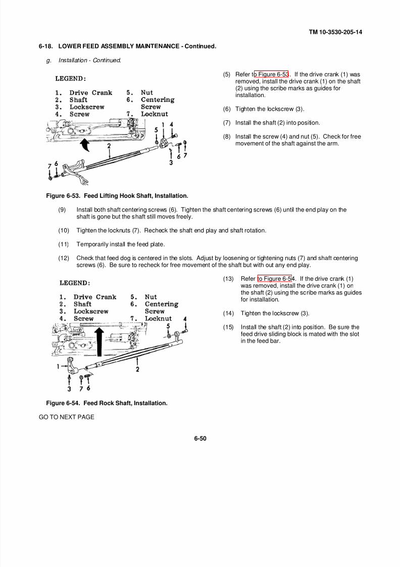
8/7/2019 TM 10-3530-205-10 CLOTHING REPAIR SHOP
http://slidepdf.com/reader/full/tm-10-3530-205-10-clothing-repair-shop 272/455
TM 10-3530-205-14
6-18. LOWER FEED ASSEMBLY MAINTENANCE - Continued.
g. Installation - Continued.
(5) Refer t o Figure 6-53 . If the drive crank (1) wasremoved, install the drive crank (1) on the shaft
(2) using the scribe marks as guides forinstallation.
(6) Tighten the lockscrew (3).
(7) Install the shaft (2) into position.
(8) Install the screw (4) and nut (5). Check for freemovement of the shaft against the arm.
Figure 6-53. Feed Lifting Hook Shaft, Installation.
(9) Install both shaft centering screws (6). Tighten the shaft centering screws (6) until the end play on theshaft is gone but the shaft still moves freely.
(10) Tighten the locknuts (7). Recheck the shaft end play and shaft rotation.
(11) Temporarily install the feed plate.
(12) Check that feed dog is centered in the slots. Adjust by loosening or tightening nuts (7) and shaft centeringscrews (6). Be sure to recheck for free movement of the shaft but with out any end play.
(13) Refer to Figure 6-5 4. If the drive crank (1)was removed, install the drive crank (1) onthe shaft (2) using the scribe marks as guidesfor installation.
(14) Tighten the lockscrew (3).
(15) Install the shaft (2) into position. Be sure thefeed drive sliding block is mated with the slotin the feed bar.
Figure 6-54. Feed Rock Shaft, Installation.
GO TO NEXT PAGE
6-50
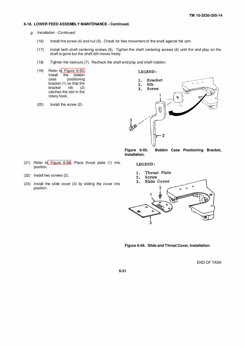
8/7/2019 TM 10-3530-205-10 CLOTHING REPAIR SHOP
http://slidepdf.com/reader/full/tm-10-3530-205-10-clothing-repair-shop 273/455
TM 10-3530-205-14
6-18. LOWER FEED ASSEMBLY MAINTENANCE - Continued.
g. Installation - Continued.
(16) Install the screw (4) and nut (5). Check for free movement of the shaft against the arm.
(17) Install both shaft centering screws (6). Tighten the shaft centering screws (6) until the end play on theshaft is gone but the shaft still moves freely.
(18) Tighten the locknuts (7). Recheck the shaft end play and shaft rotation.
(19) Refer t o Figure 6-55.Install the bobbincase positioningbracket (1) so that thebracket nib (2)catches the slot in therotary hook.
(20) Install the screw (2).
(21) Refer to Figure 6-56. Place throat plate (1) into
position.
(22) Install two screws (2).
(23) Install the slide cover (3) by sliding the cover intoposition.
Figure 6-55. Bobbin Case Positioning Bracket,Installation.
Figure 6-56. Slide and Throat Cover, Installation.
END OF TASK
6-51
8/7/2019 TM 10-3530-205-10 CLOTHING REPAIR SHOP
http://slidepdf.com/reader/full/tm-10-3530-205-10-clothing-repair-shop 274/455
TM 10-3530-205-14
6-19. B OBBIN ASSEMBLY MAINTENANCE.
This task covers:a. Removal b. Cleaning c. Inspection d. Repaire. Installation
INITIAL SETUP EquipmentConditionApplicable Configuration Para. Condition Description
All 2-12 Electrical powerremoved.
Test Equipment 2-12 Needle and threadNone removed.
2-9 Sewing machine removedSpecial Tools from table.
None 6-18a Slide and throatplates removed.
Materials/PartsCleaning Solvent Special Environmental Conditions
(Appendix E , item 2) NoneCloth, Soft, Lint-Free
(Appendix E , item 3) Personnel RequiredBrush, Medium Bristle 1 Person
(Appendix E , item 1)Grease
(Appendix E , item 4)
General Safety Instructions
WARNING
Cleaning solvent, Federal Specification P-D-680, is both toxic and flammable. Keep off skin. Use only in a well-ventilated area and avoid prolonged breathing of vapors. Keep away from open flame.
GO TO NEXT PAGE
6-52
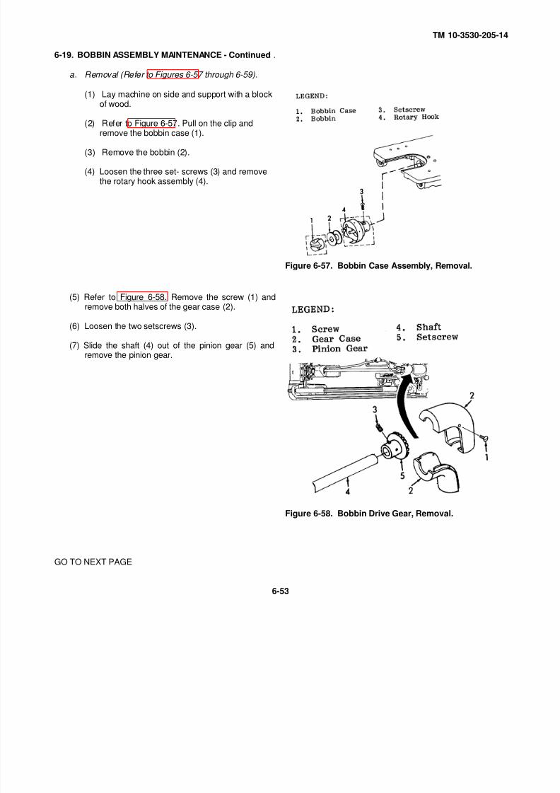
8/7/2019 TM 10-3530-205-10 CLOTHING REPAIR SHOP
http://slidepdf.com/reader/full/tm-10-3530-205-10-clothing-repair-shop 275/455
TM 10-3530-205-14
6-19. BOBBIN ASSEMBLY MAINTENANCE - Continued .
a. Removal (Refer t o Figures 6-57 through 6-59).
(1) Lay machine on side and support with a blockof wood.
(2) Refer t o Figure 6-57 . Pull on the clip andremove the bobbin case (1).
(3) Remove the bobbin (2).
(4) Loosen the three set- screws (3) and removethe rotary hook assembly (4).
(5) Refer to Figure 6-58. Remove the screw (1) andremove both halves of the gear case (2).
(6) Loosen the two setscrews (3).
(7) Slide the shaft (4) out of the pinion gear (5) andremove the pinion gear.
Figure 6-57. Bobbin Case Assembly, Removal.
Figure 6-58. Bobbin Drive Gear, Removal.
GO TO NEXT PAGE
6-53
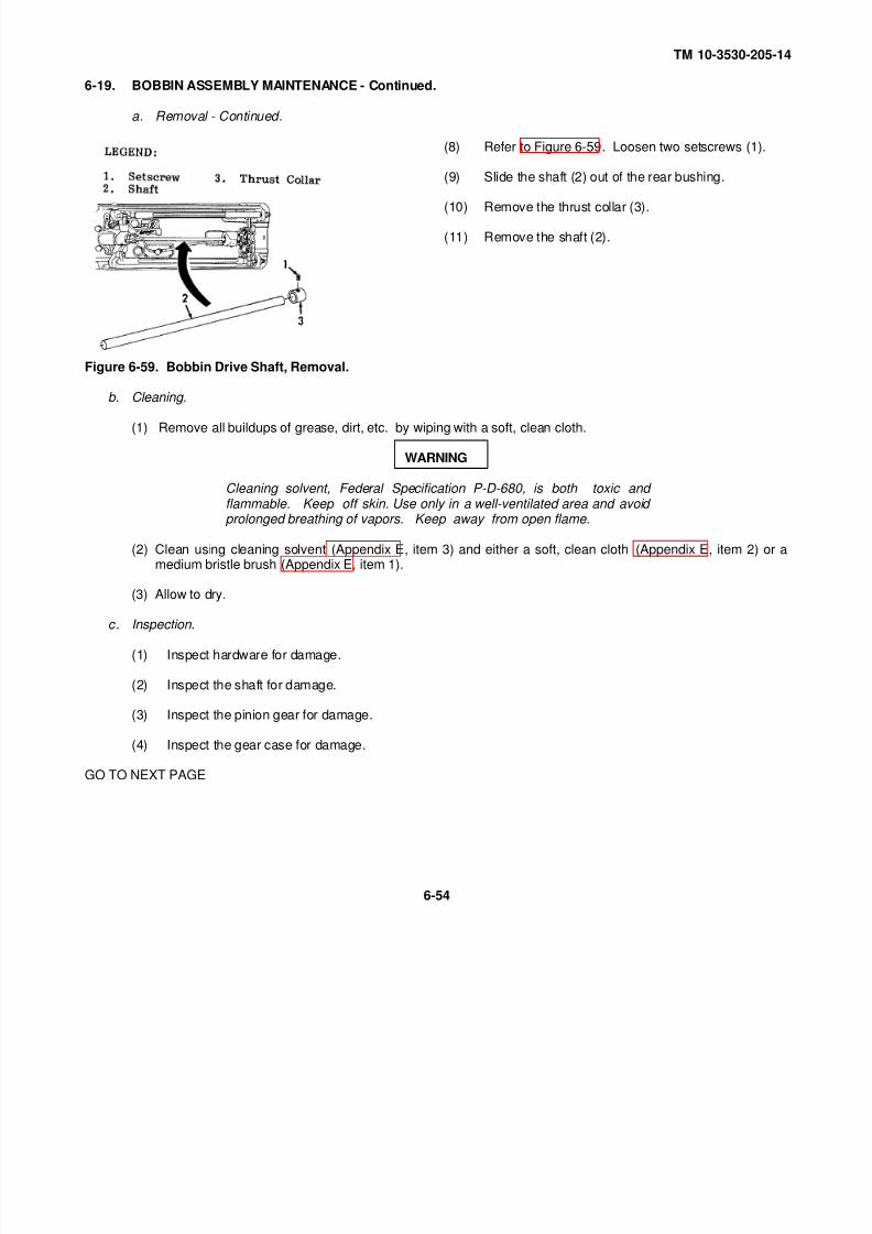
8/7/2019 TM 10-3530-205-10 CLOTHING REPAIR SHOP
http://slidepdf.com/reader/full/tm-10-3530-205-10-clothing-repair-shop 276/455
TM 10-3530-205-14
6-19. BOBBIN ASSEMBLY MAINTENANCE - Continued.
a. Removal - Continued.
(8) Refer to Figure 6-59 . Loosen two setscrews (1).
(9) Slide the shaft (2) out of the rear bushing.
(10) Remove the thrust collar (3).
(11) Remove the shaft (2).
Figure 6-59. Bobbin Drive Shaft, Removal.
b. Cleaning.
(1) Remove all buildups of grease, dirt, etc. by wiping with a soft, clean cloth.
WARNING
Cleaning solvent, Federal Specification P-D-680, is both toxic and flammable. Keep off skin. Use only in a well-ventilated area and avoid prolonged breathing of vapors. Keep away from open flame.
(2) Clean using cleaning solvent (Appendix E , item 3) and either a soft, clean cloth (Appendix E , item 2) or amedium bristle brush (Appendix E, item 1).
(3) Allow to dry.
c. Inspection.
(1) Inspect hardware for damage.
(2) Inspect the shaft for damage.
(3) Inspect the pinion gear for damage.
(4) Inspect the gear case for damage.
GO TO NEXT PAGE
6-54
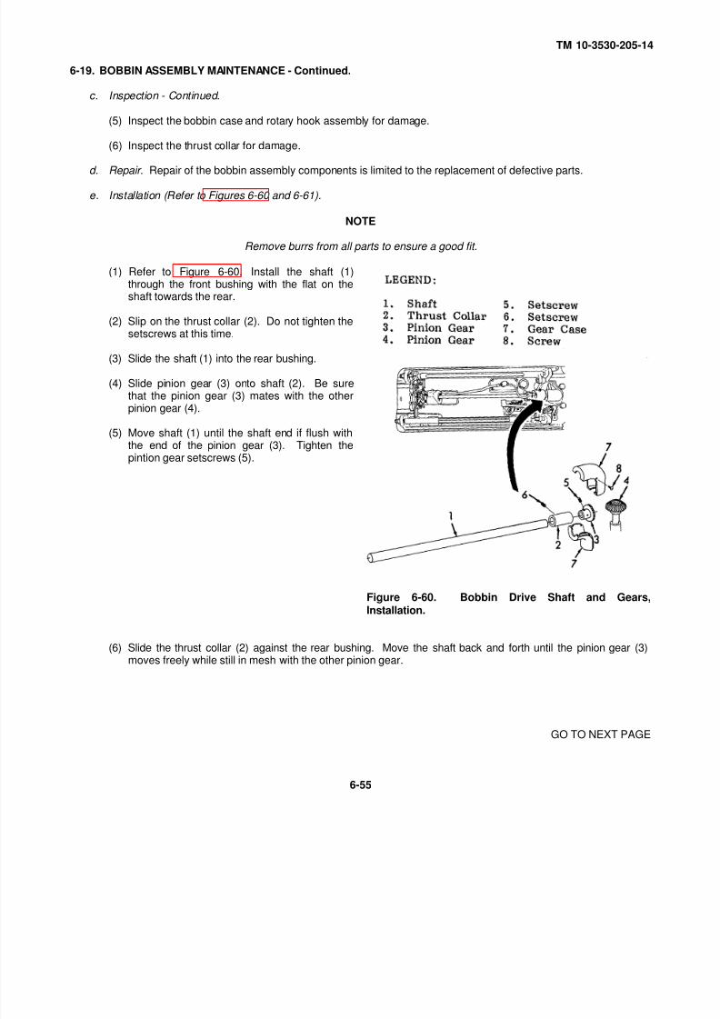
8/7/2019 TM 10-3530-205-10 CLOTHING REPAIR SHOP
http://slidepdf.com/reader/full/tm-10-3530-205-10-clothing-repair-shop 277/455
TM 10-3530-205-14
6-19. BOBBIN ASSEMBLY MAINTENANCE - Continued.
c. Inspection - Continued.
(5) Inspect the bobbin case and rotary hook assembly for damage.
(6) Inspect the thrust collar for damage.
d. Repair . Repair of the bobbin assembly components is limited to the replacement of defective parts.
e. Installation (Refer to Figures 6-60 and 6-61).
NOTE
Remove burrs from all parts to ensure a good fit.
(1) Refer to Figure 6-60. Install the shaft (1)through the front bushing with the flat on theshaft towards the rear.
(2) Slip on the thrust collar (2). Do not tighten thesetscrews at this time.
(3) Slide the shaft (1) into the rear bushing.
(4) Slide pinion gear (3) onto shaft (2). Be surethat the pinion gear (3) mates with the otherpinion gear (4).
(5) Move shaft (1) until the shaft end if flush withthe end of the pinion gear (3). Tighten thepintion gear setscrews (5).
Figure 6-60. Bobbin Drive Shaft and Gears,Installation.
(6) Slide the thrust collar (2) against the rear bushing. Move the shaft back and forth until the pinion gear (3)moves freely while still in mesh with the other pinion gear.
GO TO NEXT PAGE
6-55
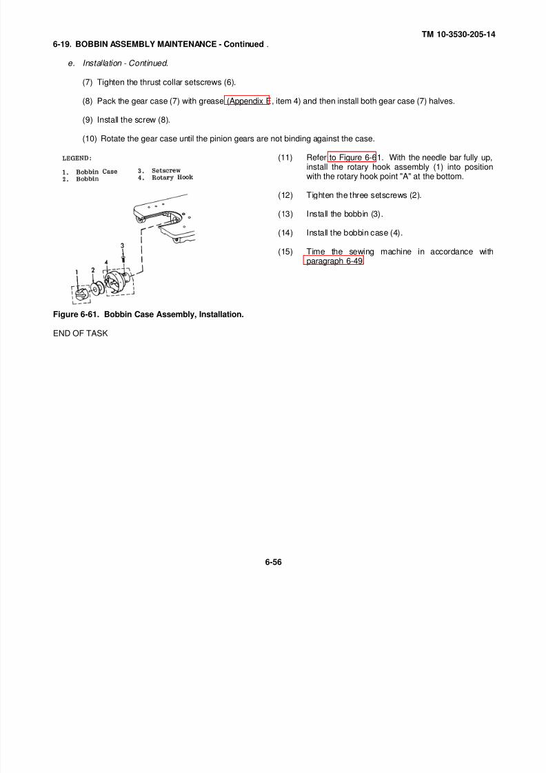
8/7/2019 TM 10-3530-205-10 CLOTHING REPAIR SHOP
http://slidepdf.com/reader/full/tm-10-3530-205-10-clothing-repair-shop 278/455
TM 10-3530-205-146-19. BOBBIN ASSEMBLY MAINTENANCE - Continued .
e. Installation - Continued.
(7) Tighten the thrust collar setscrews (6).
(8) Pack the gear case (7) with grease (Appendix E , item 4) and then install both gear case (7) halves.
(9) Install the screw (8).
(10) Rotate the gear case until the pinion gears are not binding against the case.
(11) Refer to Figure 6-6 1. With the needle bar fully up,install the rotary hook assembly (1) into positionwith the rotary hook point "A" at the bottom.
(12) Tighten the three setscrews (2).
(13) Install the bobbin (3).
(14) Install the bobbin case (4).
(15) Time the sewing machine in accordance withparagraph 6-49.
Figure 6-61. Bobbin Case Assembly, Installation.
END OF TASK
6-56
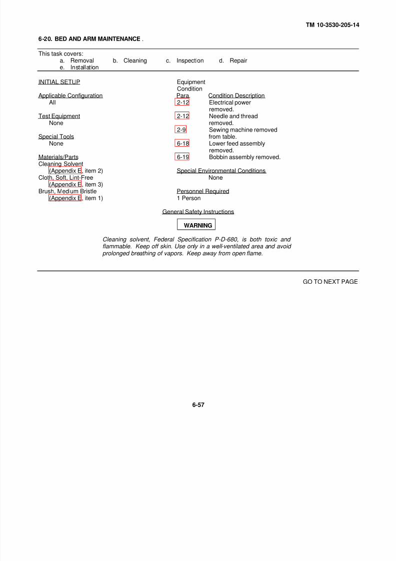
8/7/2019 TM 10-3530-205-10 CLOTHING REPAIR SHOP
http://slidepdf.com/reader/full/tm-10-3530-205-10-clothing-repair-shop 279/455
TM 10-3530-205-14
6-20. B ED AND ARM MAINTENANCE .
This task covers:a. Removal b. Cleaning c. Inspection d. Repaire. Installation
INITIAL SETUP Equipment
ConditionApplicable Configuration Para. Condition DescriptionAll 2-12 Electrical power
removed.Test Equipment 2-12 Needle and thread
None removed.2-9 Sewing machine removed
Special Tools from table.None 6-18 Lower feed assembly
removed.Materials/Parts 6-19 Bobbin assembly removed.Cleaning Solvent
(Appendix E , item 2) Special Environmental ConditionsCloth, Soft, Lint-Free None
(Appendix E , item 3)Brush, Medium Bristle Personnel Required
(Appendix E , item 1) 1 Person
General Safety Instructions
WARNING
Cleaning solvent, Federal Specification P-D-680, is both toxic and flammable. Keep off skin. Use only in a well-ventilated area and avoid prolonged breathing of vapors. Keep away from open flame.
GO TO NEXT PAGE
6-57
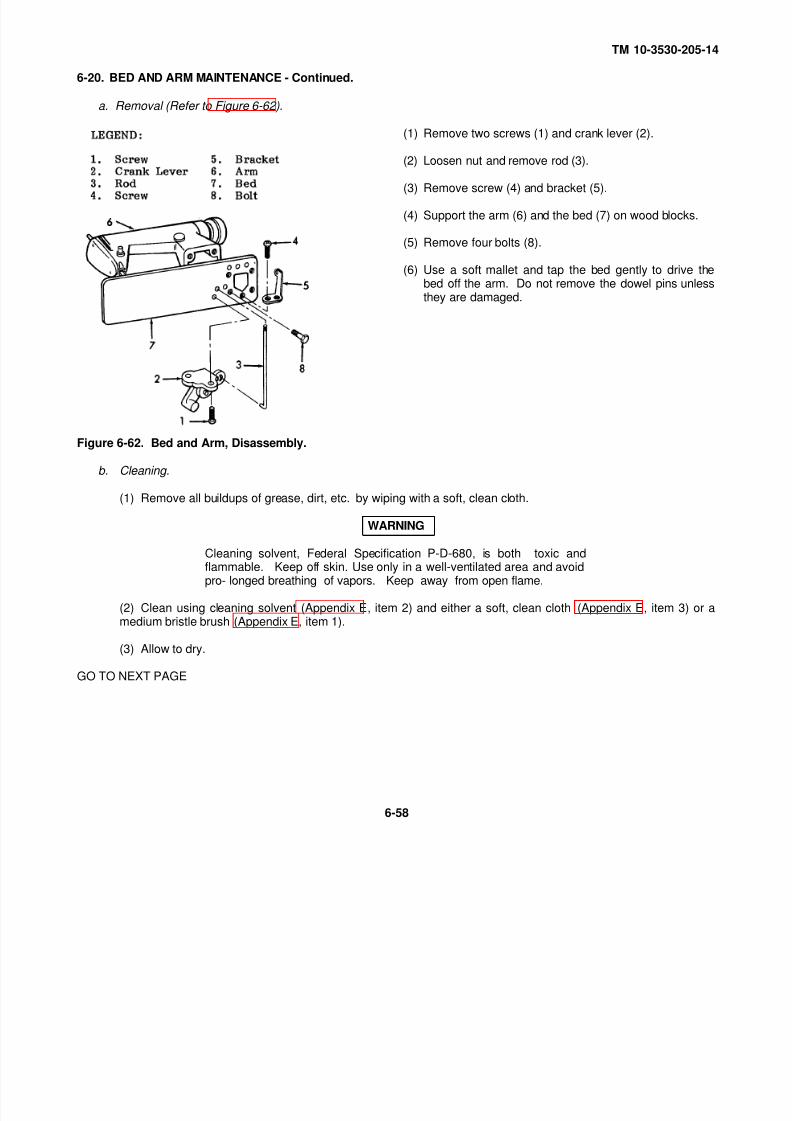
8/7/2019 TM 10-3530-205-10 CLOTHING REPAIR SHOP
http://slidepdf.com/reader/full/tm-10-3530-205-10-clothing-repair-shop 280/455
TM 10-3530-205-14
6-20. BED AND ARM MAINTENANCE - Continued.
a. Removal (Refer to Figure 6-62) .
(1) Remove two screws (1) and crank lever (2).
(2) Loosen nut and remove rod (3).
(3) Remove screw (4) and bracket (5).
(4) Support the arm (6) and the bed (7) on wood blocks.
(5) Remove four bolts (8).
(6) Use a soft mallet and tap the bed gently to drive thebed off the arm. Do not remove the dowel pins unlessthey are damaged.
Figure 6-62. Bed and Arm, Disassembly.
b. Cleaning.
(1) Remove all buildups of grease, dirt, etc. by wiping with a soft, clean cloth.
WARNING
Cleaning solvent, Federal Specification P-D-680, is both toxic andflammable. Keep off skin. Use only in a well-ventilated area and avoidpro- longed breathing of vapors. Keep away from open flame.
(2) Clean using cleaning solvent (Appendix E , item 2) and either a soft, clean cloth (Appendix E , item 3) or amedium bristle brush (Appendix E, item 1).
(3) Allow to dry.
GO TO NEXT PAGE
6-58
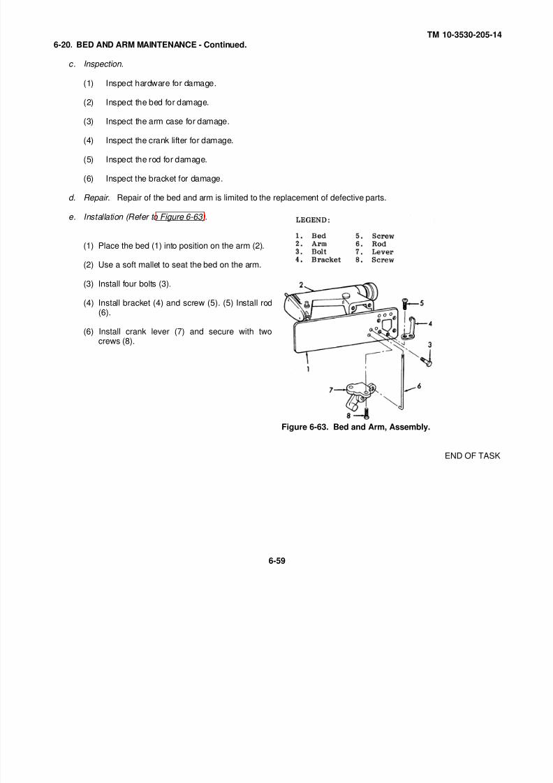
8/7/2019 TM 10-3530-205-10 CLOTHING REPAIR SHOP
http://slidepdf.com/reader/full/tm-10-3530-205-10-clothing-repair-shop 281/455
TM 10-3530-205-146-20. BED AND ARM MAINTENANCE - Continued.
c. Inspection.
(1) Inspect hardware for damage.
(2) Inspect the bed for damage.
(3) Inspect the arm case for damage.
(4) Inspect the crank lifter for damage.
(5) Inspect the rod for damage.
(6) Inspect the bracket for damage.
d. Repair . Repair of the bed and arm is limited to the replacement of defective parts.
e. Installation (Refer to Figure 6-63) .
(1) Place the bed (1) into position on the arm (2).
(2) Use a soft mallet to seat the bed on the arm.
(3) Install four bolts (3).
(4) Install bracket (4) and screw (5). (5) Install rod(6).
(6) Install crank lever (7) and secure with twocrews (8).
Figure 6-63. Bed and Arm, Assembly.
END OF TASK
6-59
8/7/2019 TM 10-3530-205-10 CLOTHING REPAIR SHOP
http://slidepdf.com/reader/full/tm-10-3530-205-10-clothing-repair-shop 282/455
TM 10-3530-205-14
6-21. P RESSER BAR AND NEEDLE BAR MAINTENANCE .
This task covers:a. Removal b. Cleaning c. Inspection d. Repaire. Installation
INITIAL SETUP Equipment
ConditionApplicable Configuration Para. Condition DescriptionAll 2-12 Electrical power
removed.Test Equipment 2-12 Needle and thread
None removed.6-13 Face plate removed.
Special Tools 6-18 Slide and throatNone plates removed.
Materials/Parts Special Environmental ConditionsCleaning Solvent None
(Appendix E , item 2)Cloth, Soft, Lint-Free Personnel Required
(Appendix E , item 3) 1 PersonBrush, Medium Bristle
(Appendix E , item 1)
General Safety Instructions
WARNING
Cleaning solvent, Federal Specification P-D-680, is both toxic and flammable. Keep off skin. Use only in a well-ventilated area and avoid prolonged breathing of vapors. Keep away from open flame.
GO TO NEXT PAGE
6-60 Change 1
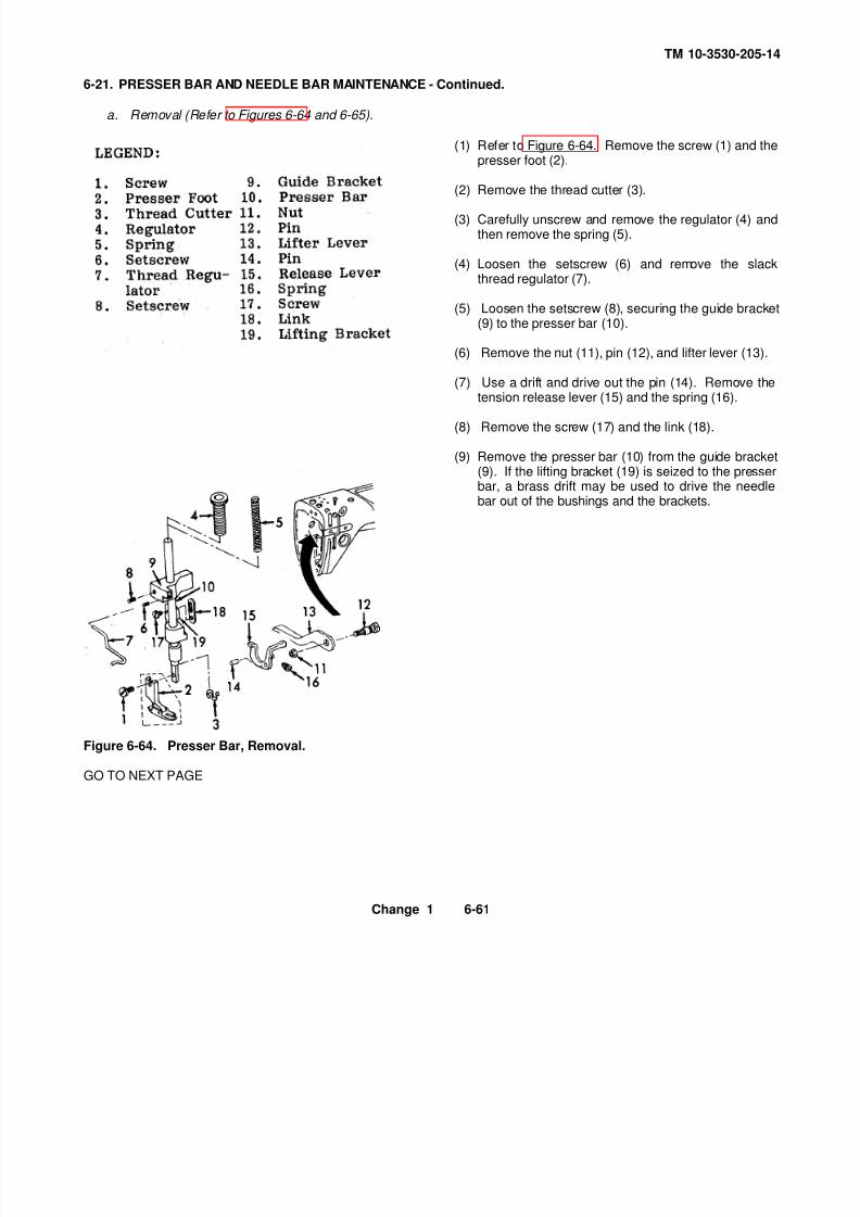
8/7/2019 TM 10-3530-205-10 CLOTHING REPAIR SHOP
http://slidepdf.com/reader/full/tm-10-3530-205-10-clothing-repair-shop 283/455
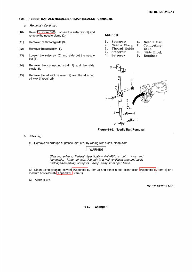
8/7/2019 TM 10-3530-205-10 CLOTHING REPAIR SHOP
http://slidepdf.com/reader/full/tm-10-3530-205-10-clothing-repair-shop 284/455
TM 10-3530-205-14
6-21. PRESSER BAR AND NEEDLE BAR MAINTENANCE - Continued.
a. Removal - Continued .
(10) Refer to Figure 6-65 . Loosen the setscrew (1) andremove the needle clamp (2).
(11) Remove the thread guide (3).
(12) Remove the setscrew (4).
(13) Loosen the setscrew (5) and slide out the needlebar (6).
(14) Remove the connecting stud (7) and the slideblock (8).
(15) Remove the oil wick retainer (9) and the attachedoil wick (if required).
Figure 6-65. Needle Bar, Removal
b Cleaning .
(1) Remove all buildups of grease, dirt, etc. by wiping with a soft, clean cloth.
WARNING
Cleaning solvent, Federal Specification P-D-680, is both toxic and flammable. Keep off skin. Use only in a well-ventilated area and avoid prolonged breathing of vapors. Keep away from open flame.
(2) Clean using cleaning solvent (Appendix E , item 2) and either a soft, clean cloth (Appendix E , item 3) or amedium bristle brush (Appendix E, item 1).
(3) Allow to dry.
GO TO NEXT PAGE
6-62 C hange 1
8/7/2019 TM 10-3530-205-10 CLOTHING REPAIR SHOP
http://slidepdf.com/reader/full/tm-10-3530-205-10-clothing-repair-shop 285/455
TM 10-3530-205-14
6-21. PRESSER BAR AND NEEDLE BAR MAINTENANCE - Continued.
c. Inspection.
(1) Inspect hardware for damage.
(2) Inspect the presser bar for damage.
(3) Inspect the presser foot for damage.
(4) Inspect the thread cutter for damage.
(5) Inspect the regulator for damage.
(6) Inspect the spring for damage.
(7) Inspect the lifter bracket for damage.
(8) Inspect the guide bracket for damage.
(9) Inspect the slack thread regulator for damage.
(10) Inspect the lifter lever for damage.
(11) Inspect the tension release lever for damage.
(12) Inspect the link for damage.
(13) Inspect the needle bar for damage.
(14) Inspect the needle clamp for damage.
(15) Inspect the thread guide for damage.
(16) Inspect the connecting stud for damage.
(17) Inspect the slide block for damage.
(18) Inspect the oil wick retainer and oil wick for damage.
d. Repair . Repair is limited to the replacement of defective parts and the removal of burrs.
GO TO NEXT PAGE
Change 1 6-63
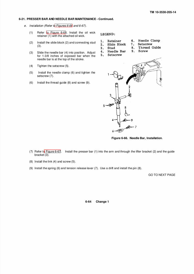
8/7/2019 TM 10-3530-205-10 CLOTHING REPAIR SHOP
http://slidepdf.com/reader/full/tm-10-3530-205-10-clothing-repair-shop 286/455
TM 10-3530-205-14
6-21. PRESSER BAR AND NEEDLE BAR MAINTENANCE - Continued.
e. Installation (Refer to Figures 6-66 and 6-67).
(1) Refer t o Figure 6-6 6. Install the oil wickretainer (1) with the attached oil wick.
(2) Install the slide block (2) and connecting stud(3).
(3) Slide the needle bar (4) into position. Adjustfor 1-3/8 inches of exposed bar when theneedle bar is at the top of the stroke.
(4) Tighten the setscrew (5).
(5) Install the needle clamp (6) and tighten thesetscrew (7).
(6) Install the thread guide (8) and screw (9).
Figure 6-66. Needle Bar, Installation.
(7) Refer to Figure 6-67 . Install the presser bar (1) into the arm and through the lifter bracket (2) and the guidebracket (3).
(8) Install the link (4) and screw (5).
(9) Install the spring (6) and tension release lever (7). Use a drift and install the pin (8).
GO TO NEXT PAGE
6-64 C hange 1
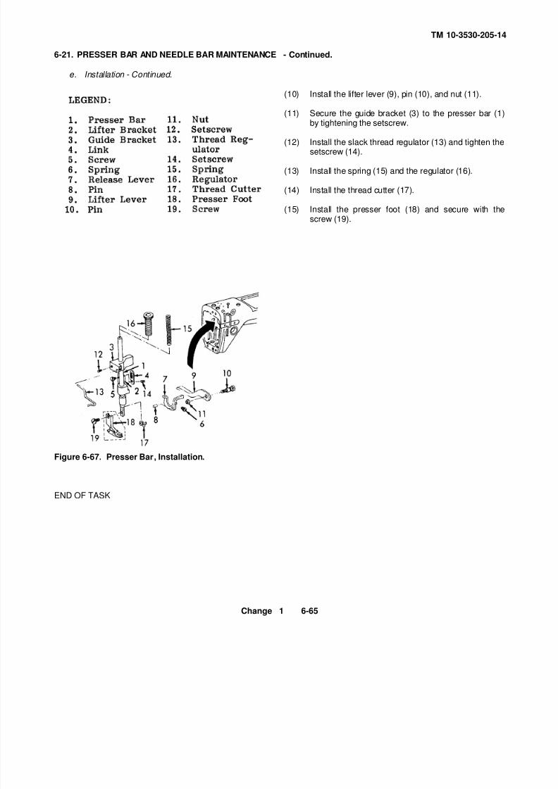
8/7/2019 TM 10-3530-205-10 CLOTHING REPAIR SHOP
http://slidepdf.com/reader/full/tm-10-3530-205-10-clothing-repair-shop 287/455
TM 10-3530-205-14
6-21. PRESSER BAR AND NEEDLE BAR MAINTENANCE - Continued.
e. Installation - Continued.
(10) Install the lifter lever (9), pin (10), and nut (11).
(11) Secure the guide bracket (3) to the presser bar (1)
by tightening the setscrew.(12) Install the slack thread regulator (13) and tighten the
setscrew (14).
(13) Install the spring (15) and the regulator (16).
(14) Install the thread cutter (17).
(15) Install the presser foot (18) and secure with thescrew (19).
Figure 6-67. Presser Bar, Installation.
END OF TASK
Change 1 6-65
8/7/2019 TM 10-3530-205-10 CLOTHING REPAIR SHOP
http://slidepdf.com/reader/full/tm-10-3530-205-10-clothing-repair-shop 288/455
TM 10-3530-205-14
6-22. LI FTING LEVER SHAFT MAINTENANCE .
This task covers:a. Removal b. Cleaning c. Inspection d Repaire. Installation
INITIAL SETUP Equipment
ConditionApplicable Configuration Para Condition DescriptionAll 2-12 Electrical power
removed.Test Equipment 2-12 Thread and needle
None removed.6-13 Face plate removed.
Special Tools 6-18 Slide and throatNone plates removed.
6-21 Presser bar and needleMaterials/Parts bar removed.Cleaning Solvent
(Appendix E , item 2) Special Environmental ConditionsCloth, Soft, Lint-Free None
(Appendix E , item 3)Brush, Medium Bristle
(Appendix E, item 1)
General Safety Instructions
WARNING
Cleaning solvent, Federal Specification P-D-680, is both toxic and flammable. Keep off skin. Use only in a well-ventilated area and avoid prolonged breathing of vapors. Keep away from open flame.
GO TO NEXT PAGE
6-66 Change 1
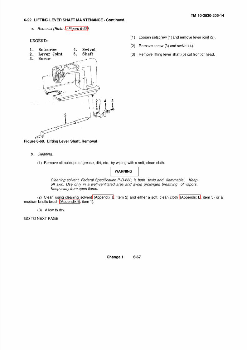
8/7/2019 TM 10-3530-205-10 CLOTHING REPAIR SHOP
http://slidepdf.com/reader/full/tm-10-3530-205-10-clothing-repair-shop 289/455
TM 10-3530-205-146-22. LIFTING LEVER SHAFT MAINTENANCE - Continued.
a. Removal (Refer t o Figure 6-68) .
(1) Loosen setscrew (1) and remove lever joint (2).
(2) Remove screw (3) and swivel (4).
(3) Remove lifting lever shaft (5) out front of head.
Figure 6-68. Lifting Lever Shaft, Removal .
b. Cleaning.
(1) Remove all buildups of grease, dirt, etc. by wiping with a soft, clean cloth.
WARNING
Cleaning solvent, Federal Specification P-D-680, is both toxic and flammable. Keep off skin. Use only in a well-ventilated area and avoid prolonged breathing of vapors.Keep away from open flame.
(2) Clean using cleaning solvent (Appendix E , item 2) and either a soft, clean cloth (Appendix E , item 3) or amedium bristle brush (Appendix E, item 1).
(3) Allow to dry.
GO TO NEXT PAGE
Change 1 6-67
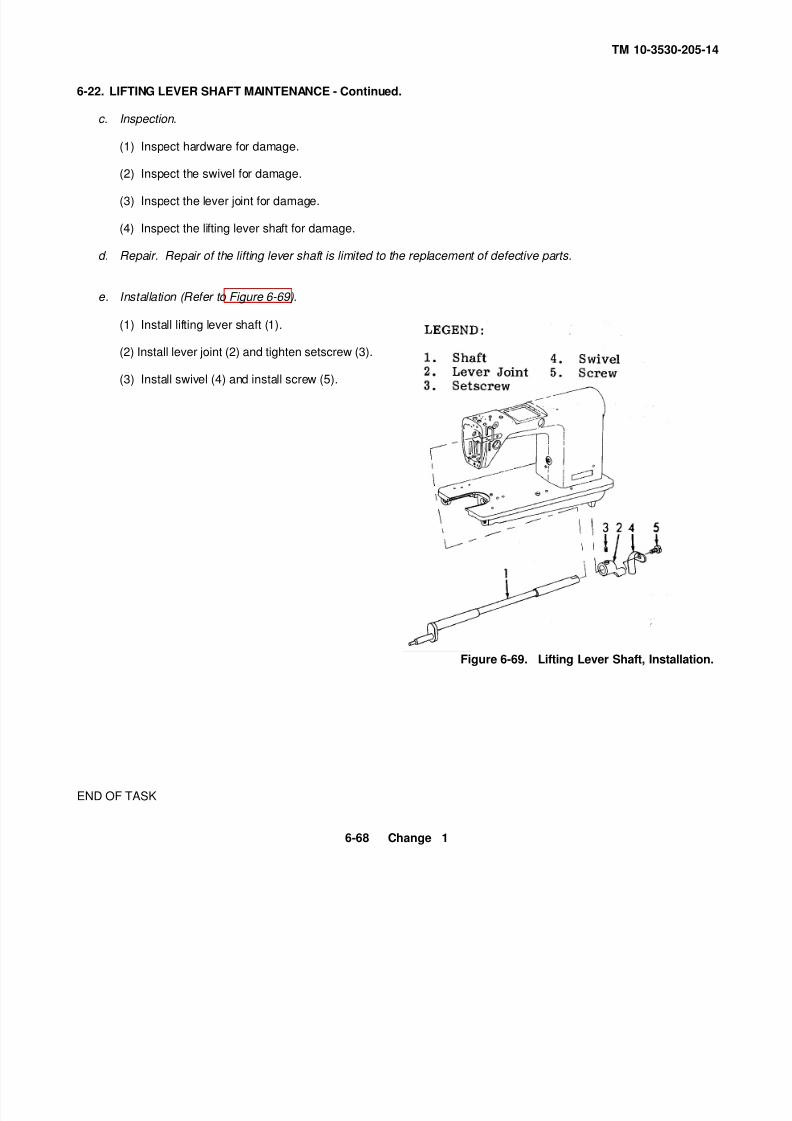
8/7/2019 TM 10-3530-205-10 CLOTHING REPAIR SHOP
http://slidepdf.com/reader/full/tm-10-3530-205-10-clothing-repair-shop 290/455
TM 10-3530-205-14
6-22. LIFTING LEVER SHAFT MAINTENANCE - Continued.
c. Inspection .
(1) Inspect hardware for damage.
(2) Inspect the swivel for damage.
(3) Inspect the lever joint for damage.
(4) Inspect the lifting lever shaft for damage.
d. Repair. Repair of the lifting lever shaft is limited to the replacement of defective parts.
e. Installation (Refer to Figure 6-69) .
(1) Install lifting lever shaft (1).
(2) Install lever joint (2) and tighten setscrew (3).
(3) Install swivel (4) and install screw (5).
Figure 6-69. Lifting Lever Shaft, Installation.
END OF TASK
6-68 C hange 1
8/7/2019 TM 10-3530-205-10 CLOTHING REPAIR SHOP
http://slidepdf.com/reader/full/tm-10-3530-205-10-clothing-repair-shop 291/455
TM 10-3530-205-146-23. U PPER SHAFT MAINTENANCE.
This task covers:a. Removal b. Cleaning c. Inspection d. Repaire. Installation
INITIAL SETUP EquipmentCondition
Applicable Configuration Para. Condition DescriptionAll 2-12 Electrical powerremoved.
Test Equipment 2-12 Needle and threadNone removed.
6-13 Face plate removed.Special Tools 6-15 Pulley removed.
None 6-18 Slide and throatplates removed.
Materials/Parts 6-24 Upper feed assemblyCleaning Solvent removed.
(Appendix E , item 2) 6-21 Presser bar and nee-Cloth, Soft, Lint-Free bar removed.
(Appendix E , item 3)Brush, Medium Bristle Special Environmental Conditions
(Appendix E , item 1) None
Personnel Required1 Person
General Safety Instructions
WARNING
Cleaning solvent, Federal Specification P-D-680, is both toxic and flammable. Keep off skin. Use only in a well-ventilated area and avoid prolonged breathing of vapors. Keep away from open flame.
GO TO NEXT PAGE
Change 1 6-69
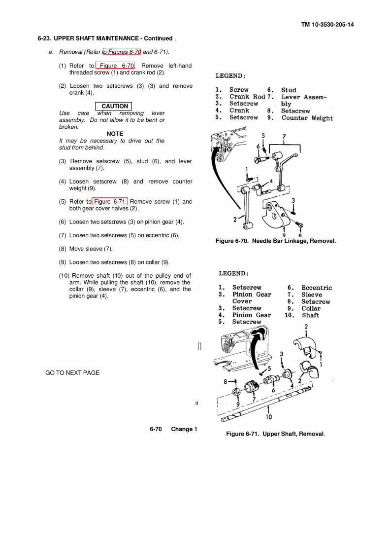
8/7/2019 TM 10-3530-205-10 CLOTHING REPAIR SHOP
http://slidepdf.com/reader/full/tm-10-3530-205-10-clothing-repair-shop 292/455
TM 10-3530-205-14
6-23. UPPER SHAFT MAINTENANCE - Continued .
a. Removal (Refer t o Figures 6-70 and 6-71).
(1) Refer to Figure 6-70. Remove left-handthreaded screw (1) and crank rod (2).
(2) Loosen two setscrews (3) (3) and removecrank (4).
CAUTIONUse care when removing lever assembly. Do not allow it to be bent or broken.
NOTEIt may be necessary to drive out the stud from behind .
(3) Remove setscrew (5), stud (6), and leverassembly (7).
(4) Loosen setscrew (8) and remove counterweight (9).
(5) Refer to Figure 6-71. Remove screw (1) andboth gear cover halves (2).
(6) Loosen two setscrews (3) on pinion gear (4).
(7) Loosen two setscrews (5) on eccentric (6).
(8) Move sleeve (7).
(9) Loosen two setscrews (8) on collar (9).
(10) Remove shaft (10) out of the pulley end ofarm. While pulling the shaft (10), remove thecollar (9), sleeve (7), eccentric (6), and thepinion gear (4).
Figure 6-70. Needle Bar Linkage, Removal.
Figure 6-71. Upper Shaft, Removal .6-70 C hange 1
GO TO NEXT PAGE
8/7/2019 TM 10-3530-205-10 CLOTHING REPAIR SHOP
http://slidepdf.com/reader/full/tm-10-3530-205-10-clothing-repair-shop 293/455
TM 10-3530-205-146-23 UPPER SHAFT MAINTENANCE - Continued .
b. Cleaning.
(1) Remove all buildups of grease, dirt, etc. by wiping with a soft, clean cloth.
WARNINGCleaning solvent, Federal Specification P-D-680, is both toxic and flammable. Keep off skin. Use only in a well-ventilated area and avoid prolonged breathing of vapors. Keep away from open flame.
(2) Clean using cleaning solvent (Appendix E , item 2) and either a soft, clean cloth (Appendix E, item 3) or amedium bristle brush (Appendix E, item 1).
(3) Allow to dry.
c. Inspection .
(1) Inspect hardware for damage.
(2) Inspect the crank rod for damage.
(3) Inspect the crank for damage.
(4) Inspect the lever assembly for damage.
(5) Inspect the counter weight for damage.
(6) Inspect the pinion gear for damage.
(7) Inspect the eccentric for damage.
(8) Inspect the sleeve for damage.
(9) Inspect the shaft for damage.
d. Repair . Repair of the upper shaft is limited to the replacement of defective parts.
GO TO NEXT PAGE
Change 1 6-71
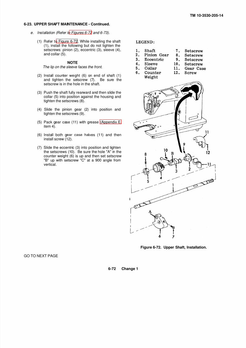
8/7/2019 TM 10-3530-205-10 CLOTHING REPAIR SHOP
http://slidepdf.com/reader/full/tm-10-3530-205-10-clothing-repair-shop 294/455
TM 10-3530-205-14
6-23. UPPER SHAFT MAINTENANCE - Continued.
e. Installation (Refer to Figures 6-72 and 6-73).
(1) Refer to Figure 6-72 . While installing the shaft(1), install the following but do not tighten thesetscrews: pinion (2), eccentric (3), sleeve (4),and collar (5).
NOTEThe lip on the sleeve faces the front .
(2) Install counter weight (6) on end of shaft (1)and tighten the setscrew (7). Be sure thesetscrew is in the hole in the shaft.
(3) Push the shaft fully rearward and then slide thecollar (5) into position against the housing andtighten the setscrews (8).
(4) Slide the pinion gear (2) into position andtighten the setscrews (9).
(5) Pack gear case (11) with grease (Appendix E,item 4).
(6) Install both gear case halves (11) and theninstall screw (12).
(7) Slide the eccentric (3) into position and tightenthe setscrews (10). Be sure the hole "A" in thecounter weight (6) is up and then set setscrew"B" up with setscrew "C" at a 900 angle fromvertical.
Figure 6-72. Upper Shaft, Installation.
GO TO NEXT PAGE
6-72 C hange 1
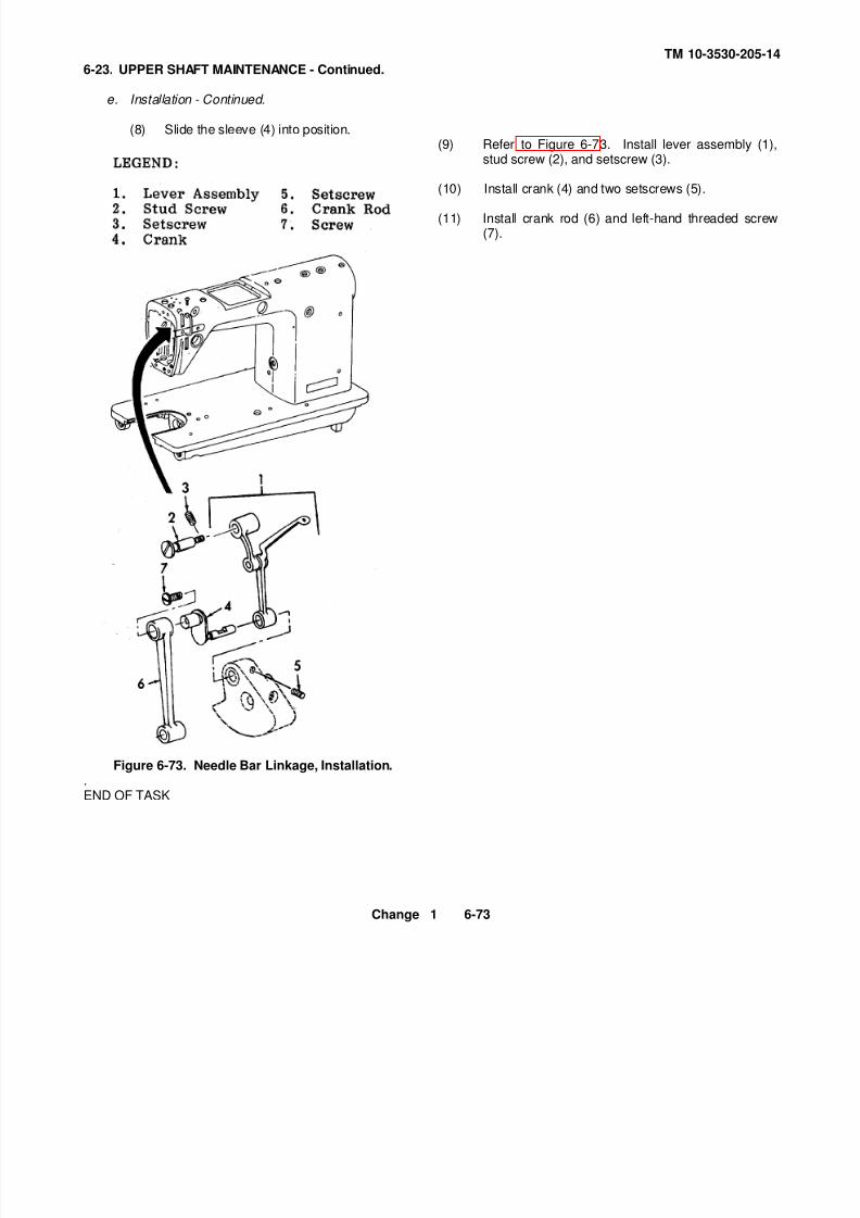
8/7/2019 TM 10-3530-205-10 CLOTHING REPAIR SHOP
http://slidepdf.com/reader/full/tm-10-3530-205-10-clothing-repair-shop 295/455
TM 10-3530-205-146-23. UPPER SHAFT MAINTENANCE - Continued.
e. Installation - Continued.
(8) Slide the sleeve (4) into position.
Figure 6-73. Needle Bar Linkage, Installation.
(9) Refer to Figure 6-7 3. Install lever assembly (1),stud screw (2), and setscrew (3).
(10) Install crank (4) and two setscrews (5).
(11) Install crank rod (6) and left-hand threaded screw(7).
.END OF TASK
Change 1 6-73
8/7/2019 TM 10-3530-205-10 CLOTHING REPAIR SHOP
http://slidepdf.com/reader/full/tm-10-3530-205-10-clothing-repair-shop 296/455
TM 10-3530-205-146-24. UP PER FEED ASSEMBLY MAINTENANCE.
This task covers:a. Removal b. Cleaning c. Inspection d. Repaire. Installation
INITIAL SETUP EquipmentCondition
Applicable Configuration Para. Condition DescriptionAll 2-12 Electrical powerremoved.
Test Equipment 2-12 Needle and threadNone removed.
2-9 Sewing machine removedSpecial Tools from table.
None 6-18 Lower feed assemblyremoved.
Materials/Parts 6-19 Bobbin assembly removed.Cleaning Solvent 6-20 Bed and arm removed.
(Appendix E , item 2)Cloth, Soft, Lint-Free Special Environmental Conditions
(Appendix E , item 3) NoneBrush, Medium Bristle(Appendix E , item 1) Personnel Required
1 Person
General Safety Instructions
WARNING
Cleaning solvent, Federal Specification P-D-680, is both toxic and flammable. Keep off skin. Use only in a well-ventilated area and avoid prolonged breathing of vapors. Keep away from open flame.
GO TO NEXT PAGE
6-74 Change 1
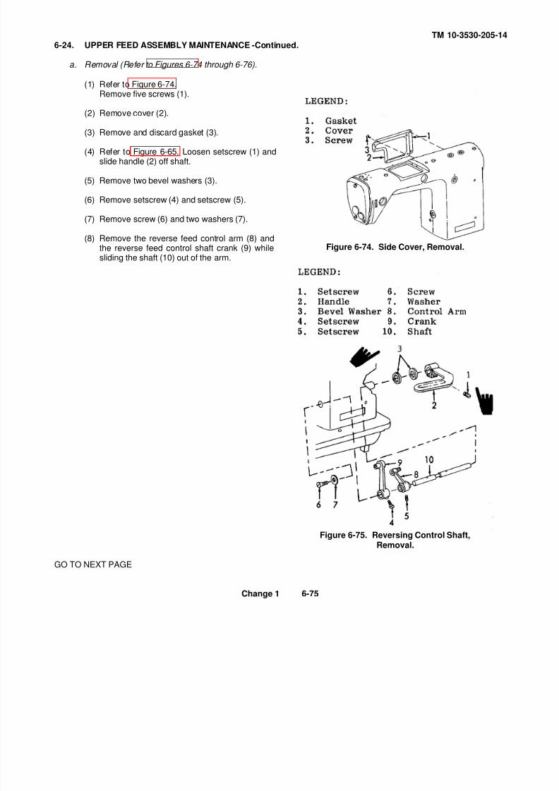
8/7/2019 TM 10-3530-205-10 CLOTHING REPAIR SHOP
http://slidepdf.com/reader/full/tm-10-3530-205-10-clothing-repair-shop 297/455
TM 10-3530-205-146-24. UPPER FEED ASSEMBLY MAINTENANCE -Continued.
a. Removal (Refer t o Figures 6-74 through 6-76).
(1) Refer to Figure 6-74.Remove five screws (1).
(2) Remove cover (2).
(3) Remove and discard gasket (3).
(4) Refer to Figure 6-65. Loosen setscrew (1) andslide handle (2) off shaft.
(5) Remove two bevel washers (3).
(6) Remove setscrew (4) and setscrew (5).
(7) Remove screw (6) and two washers (7).
(8) Remove the reverse feed control arm (8) andthe reverse feed control shaft crank (9) whilesliding the shaft (10) out of the arm.
Figure 6-74. Side Cover, Removal.
Figure 6-75. Reversing Control Shaft,Removal.
GO TO NEXT PAGE
Change 1 6-75
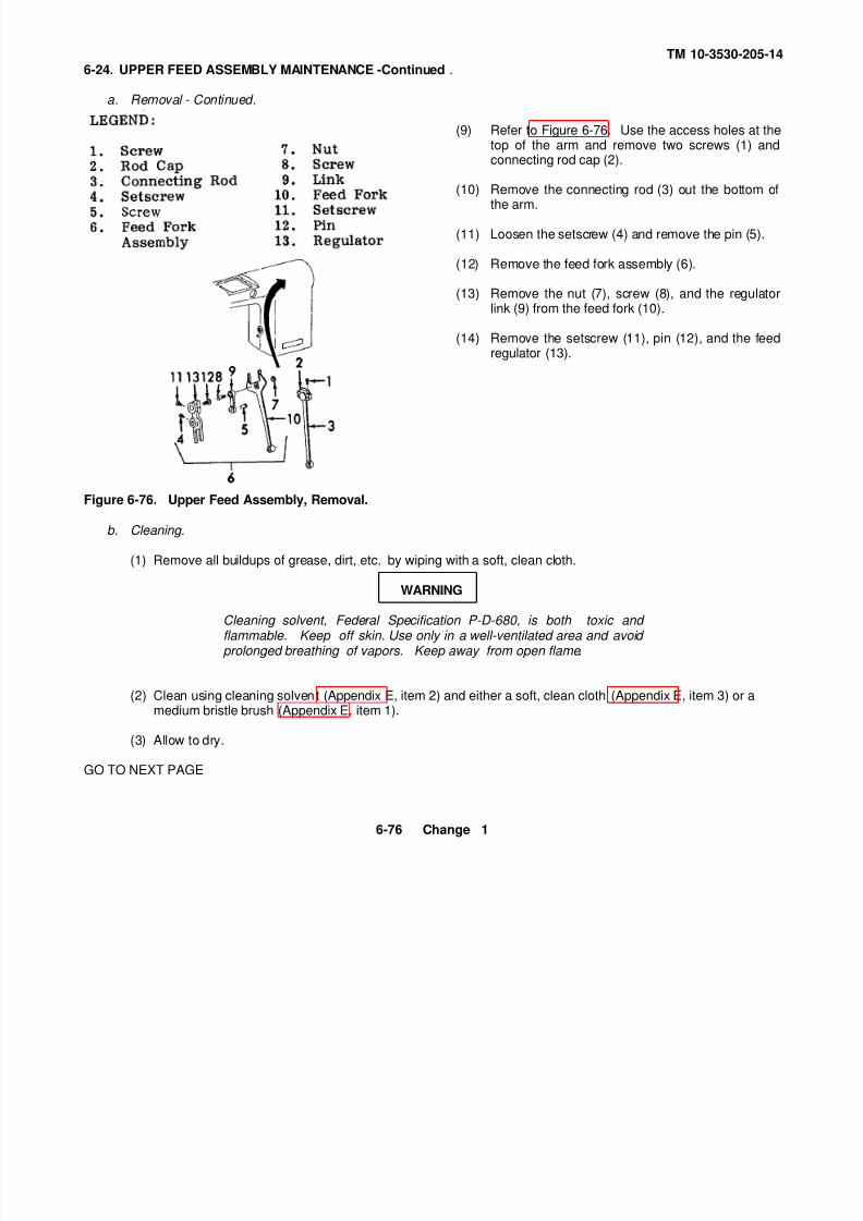
8/7/2019 TM 10-3530-205-10 CLOTHING REPAIR SHOP
http://slidepdf.com/reader/full/tm-10-3530-205-10-clothing-repair-shop 298/455
TM 10-3530-205-146-24. UPPER FEED ASSEMBLY MAINTENANCE -Continued .
a. Removal - Continued.
Figure 6-76. Upper Feed Assembly, Removal.
(9) Refer t o Figure 6-76. Use the access holes at thetop of the arm and remove two screws (1) andconnecting rod cap (2).
(10) Remove the connecting rod (3) out the bottom ofthe arm.
(11) Loosen the setscrew (4) and remove the pin (5).
(12) Remove the feed fork assembly (6).
(13) Remove the nut (7), screw (8), and the regulatorlink (9) from the feed fork (10).
(14) Remove the setscrew (11), pin (12), and the feedregulator (13).
b. Cleaning.
(1) Remove all buildups of grease, dirt, etc. by wiping with a soft, clean cloth.
WARNING
Cleaning solvent, Federal Specification P-D-680, is both toxic and flammable. Keep off skin. Use only in a well-ventilated area and avoid prolonged breathing of vapors. Keep away from open flame .
(2) Clean using cleaning solven t (Appendix E, item 2) and either a soft, clean cloth (Appendix E , item 3) or amedium bristle brush (Appendix E, item 1).
(3) Allow to dry.
GO TO NEXT PAGE
6-76 C hange 1
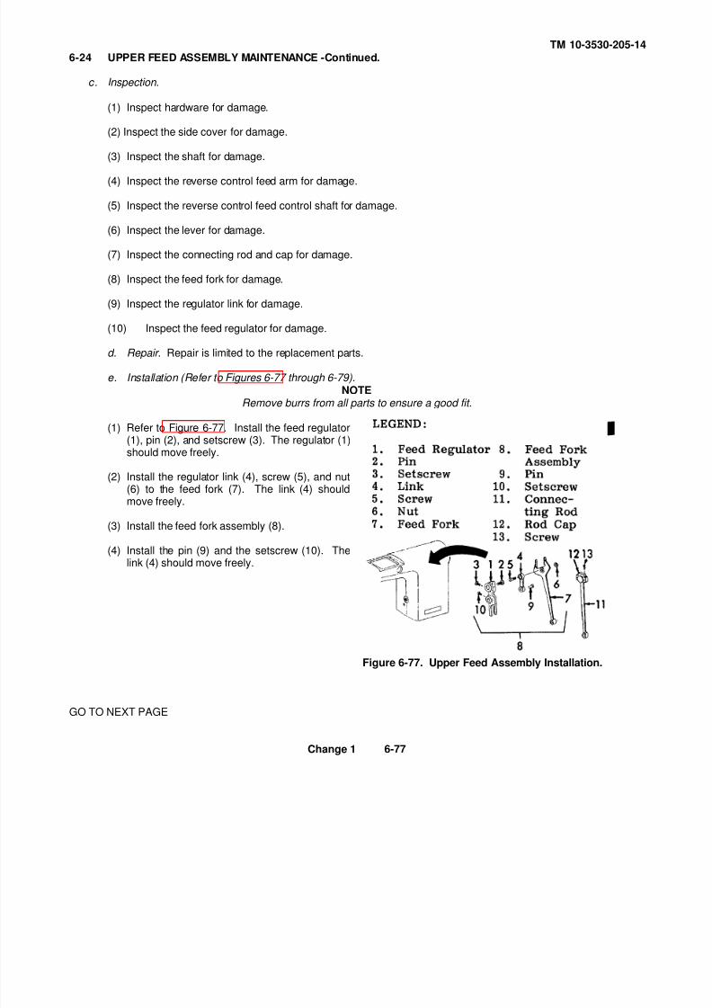
8/7/2019 TM 10-3530-205-10 CLOTHING REPAIR SHOP
http://slidepdf.com/reader/full/tm-10-3530-205-10-clothing-repair-shop 299/455
TM 10-3530-205-146-24 UPPER FEED ASSEMBLY MAINTENANCE -Continued.
c. Inspection.
(1) Inspect hardware for damage.
(2) Inspect the side cover for damage.
(3) Inspect the shaft for damage.
(4) Inspect the reverse control feed arm for damage.
(5) Inspect the reverse control feed control shaft for damage.
(6) Inspect the lever for damage.
(7) Inspect the connecting rod and cap for damage.
(8) Inspect the feed fork for damage.
(9) Inspect the regulator link for damage.
(10) Inspect the feed regulator for damage.
d. Repair . Repair is limited to the replacement parts.
e. Installation (Refer to Figures 6-77 through 6-79).NOTE
Remove burrs from all parts to ensure a good fit.
(1) Refer to Figure 6-77. Install the feed regulator(1), pin (2), and setscrew (3). The regulator (1)should move freely.
(2) Install the regulator link (4), screw (5), and nut(6) to the feed fork (7). The link (4) shouldmove freely.
(3) Install the feed fork assembly (8).
(4) Install the pin (9) and the setscrew (10). Thelink (4) should move freely.
Figure 6-77. Upper Feed Assembly Installation.
GO TO NEXT PAGE
Change 1 6-77
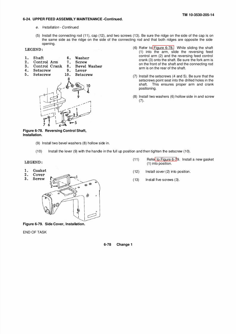
8/7/2019 TM 10-3530-205-10 CLOTHING REPAIR SHOP
http://slidepdf.com/reader/full/tm-10-3530-205-10-clothing-repair-shop 300/455
TM 10-3530-205-146-24. UPPER FEED ASSEMBLY MAINTENANCE -Continued.
e. Installation - Continued.
(5) Install the connecting rod (11), cap (12), and two screws (13). Be sure the ridge on the side of the cap is onthe same side as the ridge on the side of the connecting rod and that both ridges are opposite the sideopening.
Figure 6-78. Reversing Control Shaft,Installation.
(6) Refer to Figure 6-78. While sliding the shaft(1) into the arm, slide the reversing feedcontrol arm (2) and the reversing feed controlcrank (3) onto the shaft. Be sure the fork arm ison the front of the shaft and the connecting rodarm is on the rear of the shaft.
(7) Install the setscrews (4 and 5). Be sure that thesetscrews point seat into the drilled holes in theshaft. This ensures proper arm and crankpositioning.
(8) Install two washers (6) hollow side in and screw(7).
(9) Install two bevel washers (8) hollow side in.
(10) Install the lever (9) with the handle in the full up position and then tighten the setscrew (10).
Figure 6-79. Side Cover, Installation.
(11) Refer to Figure 6-7 9. Install a new gasket(1) into position.
(12) Install cover (2) into position.
(13) Install five screws (3).
END OF TASK
6-78 C hange 1
8/7/2019 TM 10-3530-205-10 CLOTHING REPAIR SHOP
http://slidepdf.com/reader/full/tm-10-3530-205-10-clothing-repair-shop 301/455
TM 10-3530-205-146-25. V ERTICAL SHAFT MAINTENANCE.
This task covers:a. Removal b. Cleaning c. Inspection d. Repaire. Installation
INITIAL SETUP Equipment
ConditionApplicable Configuration Para. Condition DescriptionAll 2-12 Electrical power
removed.Test Equipment 2-12 Needle and thread
None removed.6-13 Face plate removed.
Special Tools 6-15 Pulley removed.None 6-17 Lower feed assembly
removed.Materials/Parts 6-18 Slide and throatCleaning Solvent plates removed.
(Appendix E , item 2) 6-19 Bobbin assembly re-Cloth, Soft, Lint-Free moved.
(Appendix E , item 3) 6-21 Upper feed assemblyBrush, Medium Bristle removed.
(Appendix E , item 1) 6-22 Presser bar and needle-bar removed.
6-24 Upper shaft removed.Personnel Required1 Person Special Environmental Conditions
None
General Safety Instructions
WARNING
Cleaning solvent, Federal Specification P-D-680, is both toxic and flammable. Keep off skin. Use only in a well-ventilated area and avoid prolonged breathing of vapors. Keep away from open flame.
GO TO NEXT PAGE
6-79
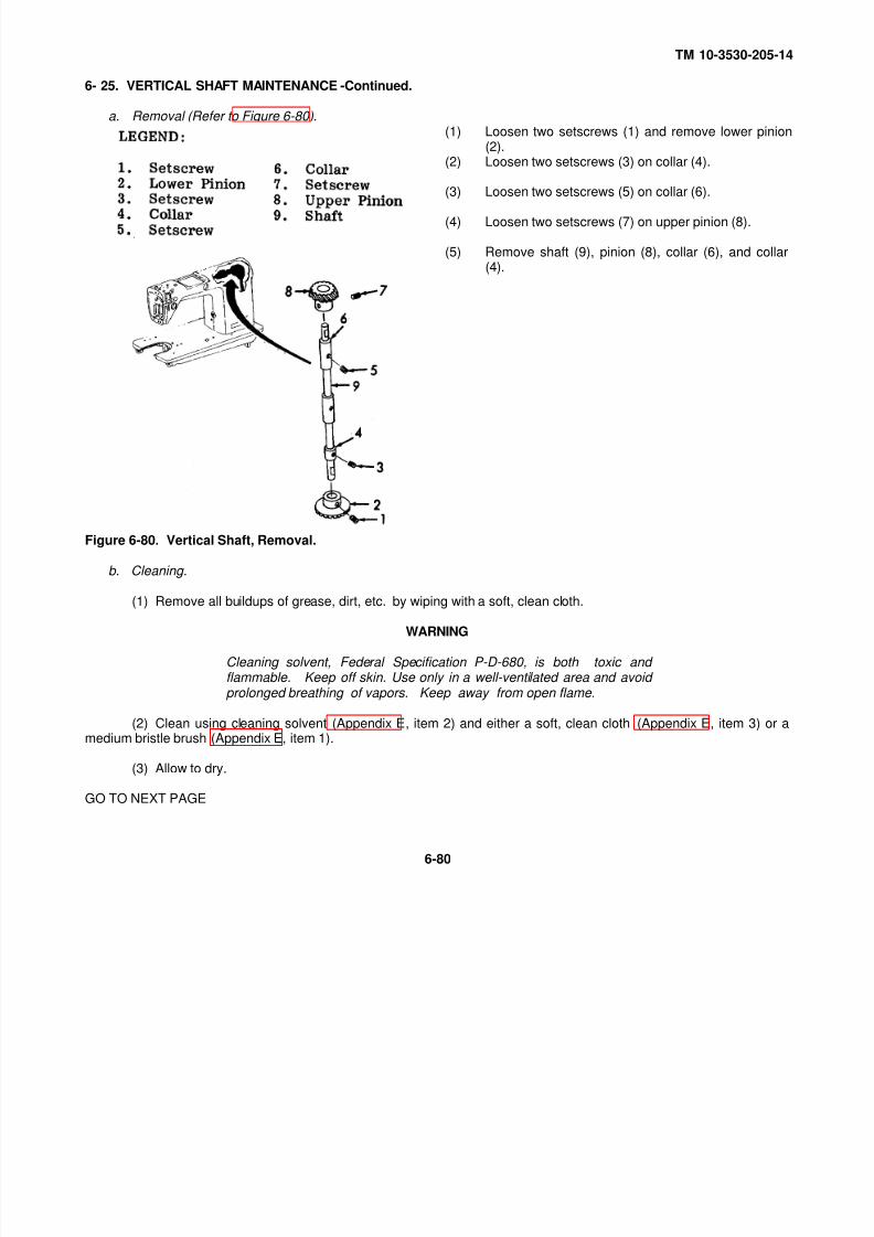
8/7/2019 TM 10-3530-205-10 CLOTHING REPAIR SHOP
http://slidepdf.com/reader/full/tm-10-3530-205-10-clothing-repair-shop 302/455
TM 10-3530-205-14
6- 25. VERTICAL SHAFT MAINTENANCE -Continued.
a. Removal (Refer t o Figure 6-80) .(1) Loosen two setscrews (1) and remove lower pinion
(2).(2) Loosen two setscrews (3) on collar (4).
(3) Loosen two setscrews (5) on collar (6).
(4) Loosen two setscrews (7) on upper pinion (8).
(5) Remove shaft (9), pinion (8), collar (6), and collar(4).
Figure 6-80. Vertical Shaft, Removal.
b. Cleaning.
(1) Remove all buildups of grease, dirt, etc. by wiping with a soft, clean cloth.
WARNING
Cleaning solvent, Federal Specification P-D-680, is both toxic and flammable. Keep off skin. Use only in a well-ventilated area and avoid prolonged breathing of vapors. Keep away from open flame.
(2) Clean using cleaning solvent (Appendix E , item 2) and either a soft, clean cloth (Appendix E , item 3) or amedium bristle brush (Appendix E, item 1).
(3) Allow to dry.
GO TO NEXT PAGE
6-80
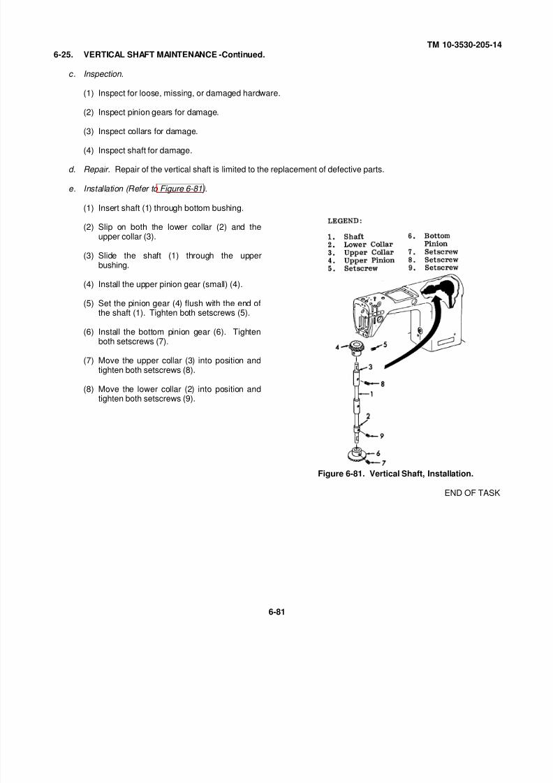
8/7/2019 TM 10-3530-205-10 CLOTHING REPAIR SHOP
http://slidepdf.com/reader/full/tm-10-3530-205-10-clothing-repair-shop 303/455
TM 10-3530-205-146-25. VERTICAL SHAFT MAINTENANCE -Continued.
c. Inspection.
(1) Inspect for loose, missing, or damaged hardware.
(2) Inspect pinion gears for damage.
(3) Inspect collars for damage.
(4) Inspect shaft for damage.
d. Repair. Repair of the vertical shaft is limited to the replacement of defective parts.
e. Installation (Refer to Figure 6-81) .
(1) Insert shaft (1) through bottom bushing.
(2) Slip on both the lower collar (2) and theupper collar (3).
(3) Slide the shaft (1) through the upperbushing.
(4) Install the upper pinion gear (small) (4).
(5) Set the pinion gear (4) flush with the end ofthe shaft (1). Tighten both setscrews (5).
(6) Install the bottom pinion gear (6). Tightenboth setscrews (7).
(7) Move the upper collar (3) into position andtighten both setscrews (8).
(8) Move the lower collar (2) into position andtighten both setscrews (9).
Figure 6-81. Vertical Shaft, Installation.
END OF TASK
6-81
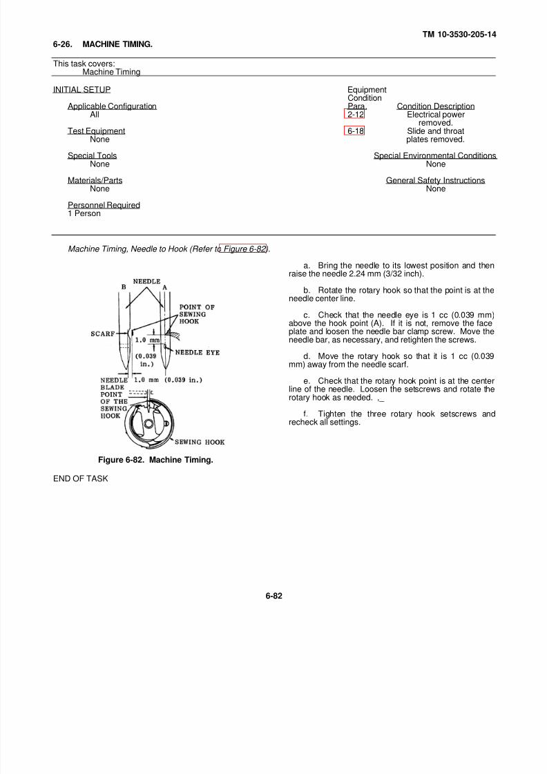
8/7/2019 TM 10-3530-205-10 CLOTHING REPAIR SHOP
http://slidepdf.com/reader/full/tm-10-3530-205-10-clothing-repair-shop 304/455
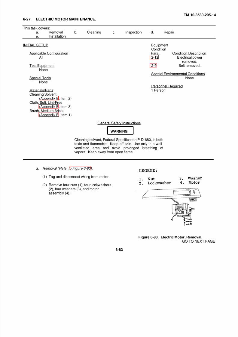
8/7/2019 TM 10-3530-205-10 CLOTHING REPAIR SHOP
http://slidepdf.com/reader/full/tm-10-3530-205-10-clothing-repair-shop 305/455
TM 10-3530-205-146-27. ELECTRIC MOTOR MAINTENANCE.
This task covers:a. Removal b. Cleaning c. Inspection d. Repaire. Installation
INITIAL SETUP EquipmentCondition
Applicable Configuration Para. Condition DescriptionAll 2-12 Electrical powerremoved.
Test Equipment 2-9 Belt removed.None
Special Environmental ConditionsSpecial Tools None
NonePersonnel Required
Materials/Parts 1 PersonCleaning Solvent
(Appendix E , item 2)Cloth, Soft, Lint-Free
(Appendix E , item 3)Brush, Medium Bristle
(Appendix E, item 1)
General Safety Instructions
WARNING
Cleaning solvent, Federal Specification P-D-680, is bothtoxic and flammable. Keep off skin. Use only in a well-ventilated area and avoid prolonged breathing ofvapors. Keep away from open flame.
a. Removal (Refer t o Figure 6-83) .
(1) Tag and disconnect wiring from motor.
(2) Remove four nuts (1), four lockwashers(2), four washers (3), and motorassembly (4).
Figure 6-83. Electric Motor, Removal.GO TO NEXT PAGE
6-83
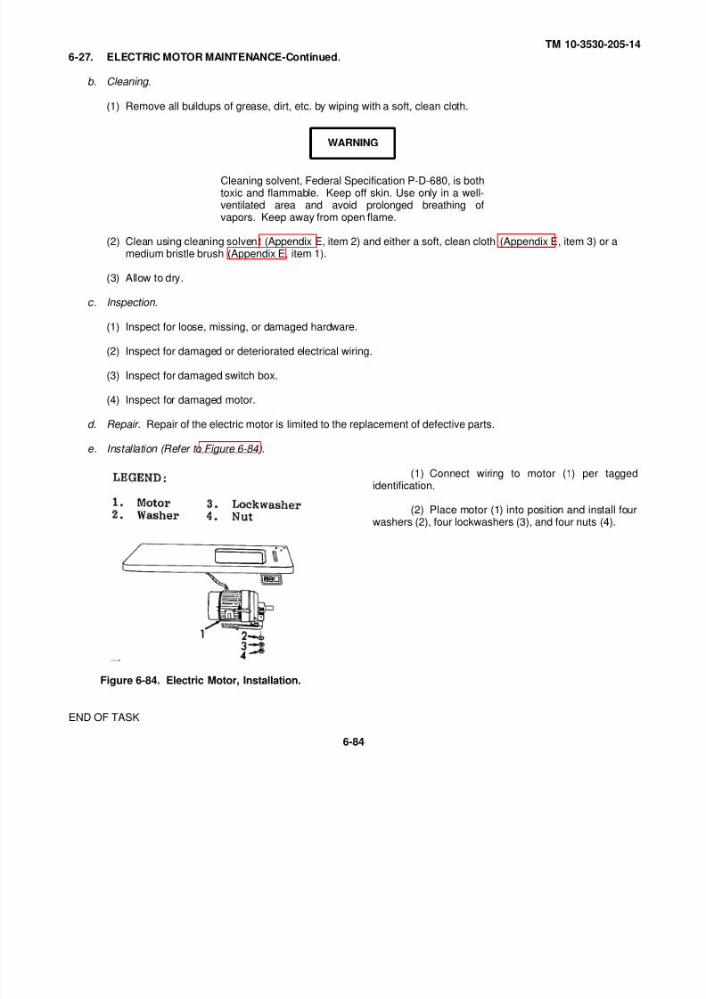
8/7/2019 TM 10-3530-205-10 CLOTHING REPAIR SHOP
http://slidepdf.com/reader/full/tm-10-3530-205-10-clothing-repair-shop 306/455
TM 10-3530-205-146-27. ELECTRIC MOTOR MAINTENANCE-Continued.
b. Cleaning.
(1) Remove all buildups of grease, dirt, etc. by wiping with a soft, clean cloth.
WARNING
Cleaning solvent, Federal Specification P-D-680, is bothtoxic and flammable. Keep off skin. Use only in a well-ventilated area and avoid prolonged breathing ofvapors. Keep away from open flame.
(2) Clean using cleaning solven t (Appendix E, item 2) and either a soft, clean cloth (Appendix E , item 3) or amedium bristle brush (Appendix E, item 1).
(3) Allow to dry.
c. Inspection.
(1) Inspect for loose, missing, or damaged hardware.
(2) Inspect for damaged or deteriorated electrical wiring.
(3) Inspect for damaged switch box.
(4) Inspect for damaged motor.
d. Repair. Repair of the electric motor is limited to the replacement of defective parts.
e. Installation (Refer to Figure 6-84) .
Figure 6-84. Electric Motor, Installation.
(1) Connect wiring to motor (1) per taggedidentification.
(2) Place motor (1) into position and install fourwashers (2), four lockwashers (3), and four nuts (4).
END OF TASK
6-84
8/7/2019 TM 10-3530-205-10 CLOTHING REPAIR SHOP
http://slidepdf.com/reader/full/tm-10-3530-205-10-clothing-repair-shop 307/455
TM 10-3530-205-14
SECTION IV. MAINTENANCE OF DARNING SEWING MACHINE
Para. Para.Electric Motor Maintenance............................. ... .6-37 Needle Thread TensionGeneral................................ .......................... ..... 6-28 Assembly Maintenance................ .....6-30
Hook Shaft Assembly Mainte- Pulley Maintenance ......................... .... 6-34nance ................................ ......................... .... 6-31 Thread Guides Mainte-Machine Timing ................................ ............. ..... 6-36 nance . ................................ ......... ....6-29Needle Bar and Presser Bar Upper Shaft Assembly
Assembly Maintenance............................... . ...6-33 Maintenance................................ . ....6-35Vertical Shaft Assembly
Maintenance................................ . ....6-32
6-28. G ENERAL.
This section contains information on the removal, disassembly, cleaning, inspection, repair, assembly, installation, andadjustment of the various parts of the darning sewing machine.
6-85
8/7/2019 TM 10-3530-205-10 CLOTHING REPAIR SHOP
http://slidepdf.com/reader/full/tm-10-3530-205-10-clothing-repair-shop 308/455
TM 10-3530-205-14
6-29. THREAD GUIDES MAINTENANCE.
This task covers:a. Removal b. Disassembly c. Cleaning d. Inspectione. Repair f. Assembly g. Installation
INITIAL SETUP Equipment
ConditionApplicable Configuration Para. Condition DescriptionAll 2-12 Electrical power
removed.Test Equipment 2-13 Thread and needle
None removed.
Special Environmental ConditionsSpecial Tools None
NonePersonnel Required
Materials/Parts 1 PersonCleaning Solvent
(Appendix E , item 2)Cloth, Soft, Lint-Free
(Appendix E , item 3)Brush, Medium Bristle
(Appendix E, item 1)
General Safety Instructions
WARNING
Cleaning solvent, Federal Specification P-D-680, is bothtoxic and flammable. Keep off skin. Use only in a well-ventilated area and avoid prolonged breathing ofvapors. Keep away from open flame.
GO TO NEXT PAGE
6-86
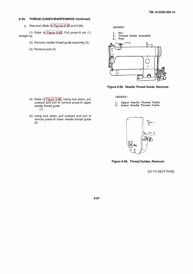
8/7/2019 TM 10-3530-205-10 CLOTHING REPAIR SHOP
http://slidepdf.com/reader/full/tm-10-3530-205-10-clothing-repair-shop 309/455
TM 10-3530-205-14
6-29. THREAD GUIDES MAINTENANCE-Continued.
a. Removal (Refer t o Figures 6-85 and 6-86).
(1) Refer to Figure 6-85 . Pull press-fit pin (1)straight up.
(2) Remove needle thread guide assembly (2).
(3) Remove post (3).
(4) Refer to Figure 6-86. Using lock pliers, pulloutward and turn to remove press-fit upperneedle thread guide
(1).
(5) Using lock pliers, pull outward and turn toremove press-fit lower needle thread guide(2).
Figure 6-85. Needle Thread Guide, Removal.
Figure 6-86. Thread Guides, Removal.
GO TO NEXT PAGE
6-87
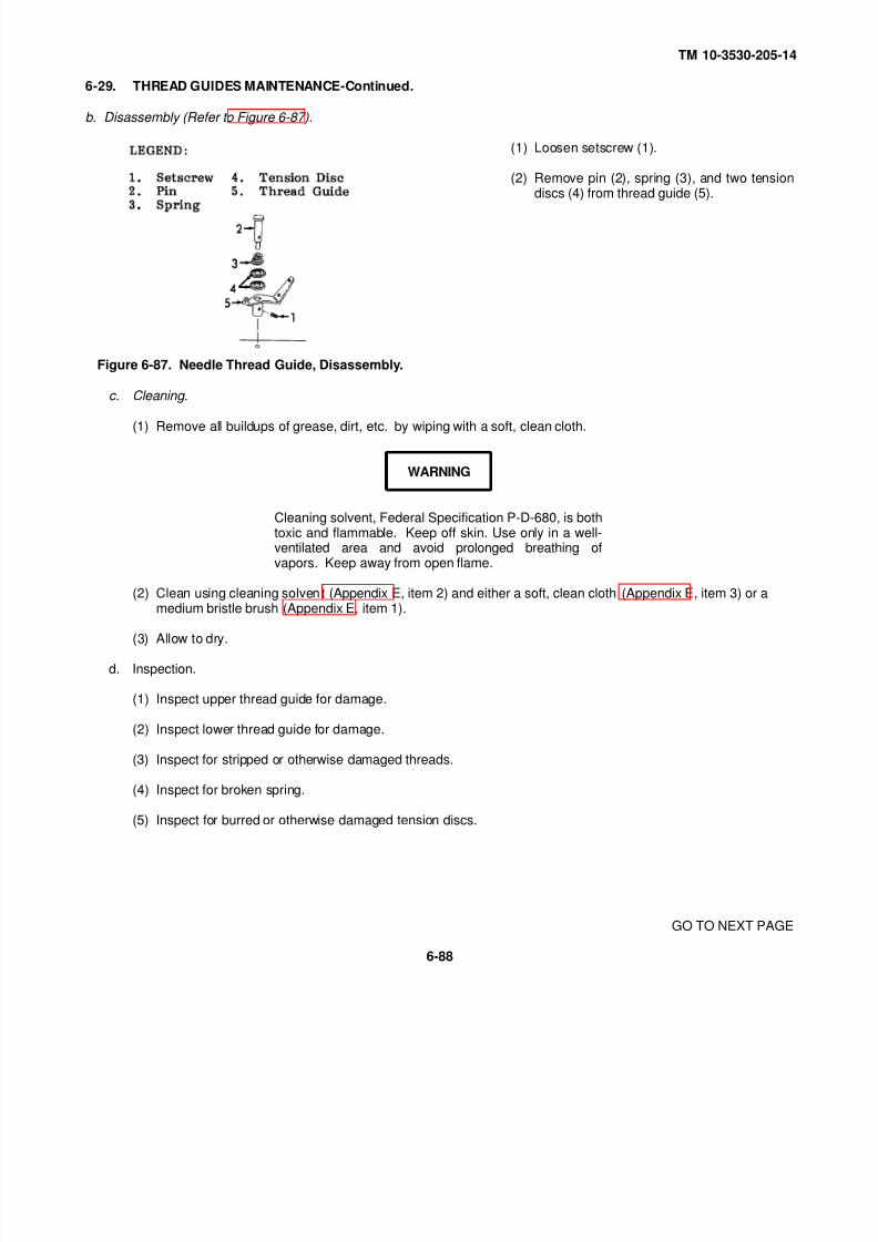
8/7/2019 TM 10-3530-205-10 CLOTHING REPAIR SHOP
http://slidepdf.com/reader/full/tm-10-3530-205-10-clothing-repair-shop 310/455
TM 10-3530-205-14
6-29. THREAD GUIDES MAINTENANCE-Continued.
b. Disassembly (Refer t o Figure 6-87) .
Figure 6-87. Needle Thread Guide, Disassembly.
(1) Loosen setscrew (1).
(2) Remove pin (2), spring (3), and two tension
discs (4) from thread guide (5).
c. Cleaning.(1) Remove all buildups of grease, dirt, etc. by wiping with a soft, clean cloth.
WARNING
Cleaning solvent, Federal Specification P-D-680, is bothtoxic and flammable. Keep off skin. Use only in a well-ventilated area and avoid prolonged breathing ofvapors. Keep away from open flame.
(2) Clean using cleaning solven t (Appendix E, item 2) and either a soft, clean cloth (Appendix E , item 3) or amedium bristle brush (Appendix E, item 1).
(3) Allow to dry.
d. Inspection.
(1) Inspect upper thread guide for damage.
(2) Inspect lower thread guide for damage.
(3) Inspect for stripped or otherwise damaged threads.
(4) Inspect for broken spring.
(5) Inspect for burred or otherwise damaged tension discs.
GO TO NEXT PAGE
6-88
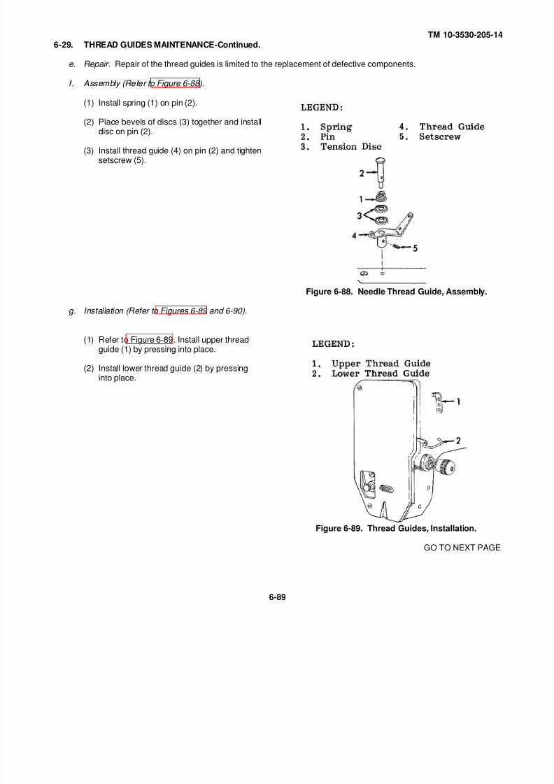
8/7/2019 TM 10-3530-205-10 CLOTHING REPAIR SHOP
http://slidepdf.com/reader/full/tm-10-3530-205-10-clothing-repair-shop 311/455
TM 10-3530-205-146-29. THREAD GUIDES MAINTENANCE-Continued.
e. Repair. Repair of the thread guides is limited to the replacement of defective components.
f. Assembly (Refer t o Figure 6-88) .
(1) Install spring (1) on pin (2).
(2) Place bevels of discs (3) together and installdisc on pin (2).
(3) Install thread guide (4) on pin (2) and tightensetscrew (5).
Figure 6-88. Needle Thread Guide, Assembly.
g. Installation (Refer to Figures 6-89 and 6-90).
(1) Refer to Figure 6-89 . Install upper threadguide (1) by pressing into place.
(2) Install lower thread guide (2) by pressing
into place.
Figure 6-89. Thread Guides, Installation.
GO TO NEXT PAGE
6-89
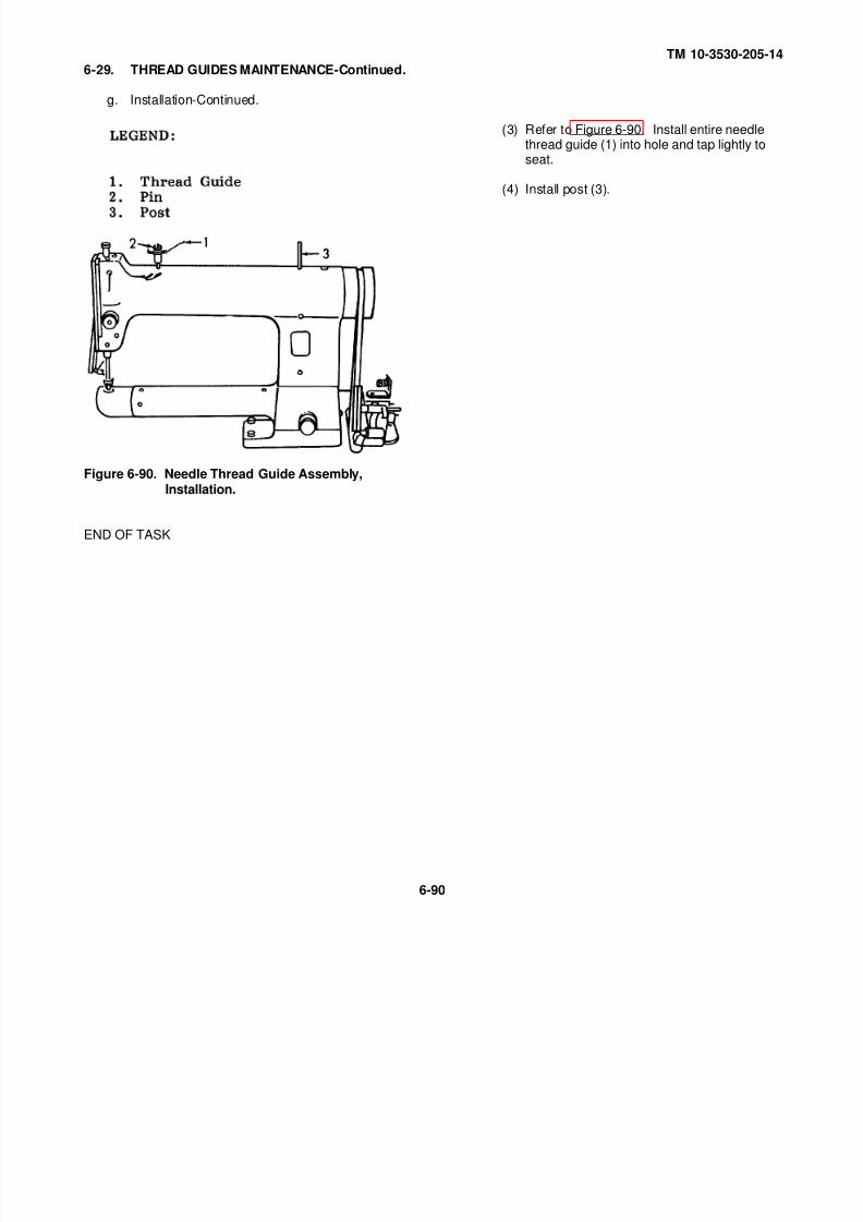
8/7/2019 TM 10-3530-205-10 CLOTHING REPAIR SHOP
http://slidepdf.com/reader/full/tm-10-3530-205-10-clothing-repair-shop 312/455
TM 10-3530-205-146-29. THREAD GUIDES MAINTENANCE-Continued.
g. Installation-Continued.
Figure 6-90. Needle Thread Guide Assembly,Installation.
(3) Refer to Figure 6-90. Install entire needlethread guide (1) into hole and tap lightly toseat.
(4) Install post (3).
END OF TASK
6-90
8/7/2019 TM 10-3530-205-10 CLOTHING REPAIR SHOP
http://slidepdf.com/reader/full/tm-10-3530-205-10-clothing-repair-shop 313/455
TM 10-3530-205-146-30. NEEDLE THREAD TENSION ASSEMBLY MAINTENANCE.
This task covers:a. Removal b. Cleaning c. Inspection d. Repaire. Installation
INITIAL SETUP EquipmentCondition
Applicable Configuration Para. Condition DescriptionAll 2-12 Electrical powerremoved.
Test Equipment 2-13 Thread and needleNone removed.
Special Environmental ConditionsSpecial Tools None
NonePersonnel Required
Materials/Parts 1 PersonCleaning Solvent
(Appendix E , item 2)Cloth, Soft, Lint-Free
(Appendix E , item 3)Brush, Medium Bristle
(Appendix E, item 1)
General Safety Instructions
WARNING
Cleaning solvent, Federal Specification P-D-680, is bothtoxic and flammable. Keep off skin. Use only in a well-ventilated area and avoid prolonged breathing ofvapors. Keep away from open flame.
GO TO NEXT PAGE
6-91
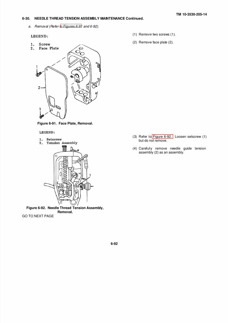
8/7/2019 TM 10-3530-205-10 CLOTHING REPAIR SHOP
http://slidepdf.com/reader/full/tm-10-3530-205-10-clothing-repair-shop 314/455
TM 10-3530-205-146-30. NEEDLE THREAD TENSION ASSEMBLY MAINTENANCE Continued.
a. Removal (Refer t o Figures 6-91 and 6-92).
Figure 6-91. Face Plate, Removal.
Figure 6-92. Needle Thread Tension Assembly,Removal.
(1) Remove two screws (1).
(2) Remove face plate (2).
(3) Refer to Figure 6-92. Loosen setscrew (1)but do not remove.
(4) Carefully remove needle guide tensionassembly (2) as an assembly.
GO TO NEXT PAGE
6-92
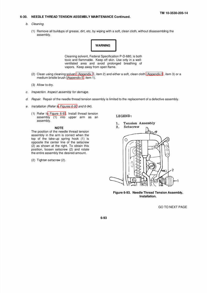
8/7/2019 TM 10-3530-205-10 CLOTHING REPAIR SHOP
http://slidepdf.com/reader/full/tm-10-3530-205-10-clothing-repair-shop 315/455
TM 10-3530-205-146-30. NEEDLE THREAD TENSION ASSEMBLY MAINTENANCE Continued.
b. Cleaning.
(1) Remove all buildups of grease, dirt, etc. by wiping with a soft, clean cloth, without disassembling theassembly.
WARNING
Cleaning solvent, Federal Specification P-D-680, is bothtoxic and flammable. Keep off skin. Use only in a well-ventilated area and avoid prolonged breathing ofvapors. Keep away from open flame.
(2) Clean using cleaning solven t (Appendix E, item 2) and either a soft, clean cloth (Appendix E , item 3) or amedium bristle brush (Appendix E, item 1).
(3) Allow to dry.
c. Inspection. Inspect assembly for damage.
d. Repair. Repair of the needle thread tension assembly is limited to the replacement of a defective assembly.
e. Installation (Refer to Figures 6-93 and 6-94).
(1) Refer to Figure 6-93 . Install thread tensionassembly (1) into upper arm as anassembly.
NOTEThe position of the needle thread tensionassembly in the arm is correct when thetop of the take-up spring hook (1) isopposite the center line of the setscrew(2) as shown at the right. To obtain thisposition, loosen setscrew (2) and rotatethe entire assembly the desired amount.
(2) Tighten setscrew (2).
Figure 6-93. Needle Thread Tension Assembly,Installation.
GO TO NEXT PAGE
6-93
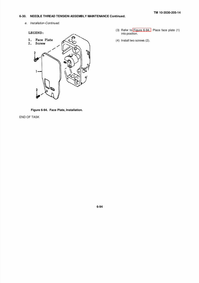
8/7/2019 TM 10-3530-205-10 CLOTHING REPAIR SHOP
http://slidepdf.com/reader/full/tm-10-3530-205-10-clothing-repair-shop 316/455
TM 10-3530-205-146-30. NEEDLE THREAD TENSION ASSEMBLY MAINTENANCE Continued.
e. Installation-Continued.
Figure 6-94. Face Plate, Installation.
(3) Refer to Figure 6-94. Place face plate (1)into position.
(4) Install two screws (2).
END OF TASK
6-94
8/7/2019 TM 10-3530-205-10 CLOTHING REPAIR SHOP
http://slidepdf.com/reader/full/tm-10-3530-205-10-clothing-repair-shop 317/455
TM 10-3530-205-146-31. HOOK SHAFT ASSEMBLY MAINTENANCE.
This task covers:a. Removal b. Disassembly c. Cleaning d. Inspectione. Repair f. Assembly g. Installation
INITIAL SETUP EquipmentCondition
Applicable Configuration Para. Condition DescriptionAll 2-12 Electrical powerremoved.
Test Equipment 2-13 Thread and needleNone removed.
Special Environmental ConditionsSpecial Tools None
NonePersonnel Required
Materials/Parts 1 PersonCleaning Solvent
(Appendix E , item 2)Cloth, Soft, Lint-Free
(Appendix E , item 3)Brush, Medium Bristle
(Appendix E, item 1)
General Safety Instructions
WARNING
Cleaning solvent, Federal Specification P-D-680, is bothtoxic and flammable. Keep off skin. Use only in a well-ventilated area and avoid prolonged breathing ofvapors. Keep away from open flame.
GO TO NEXT PAGE
6-95
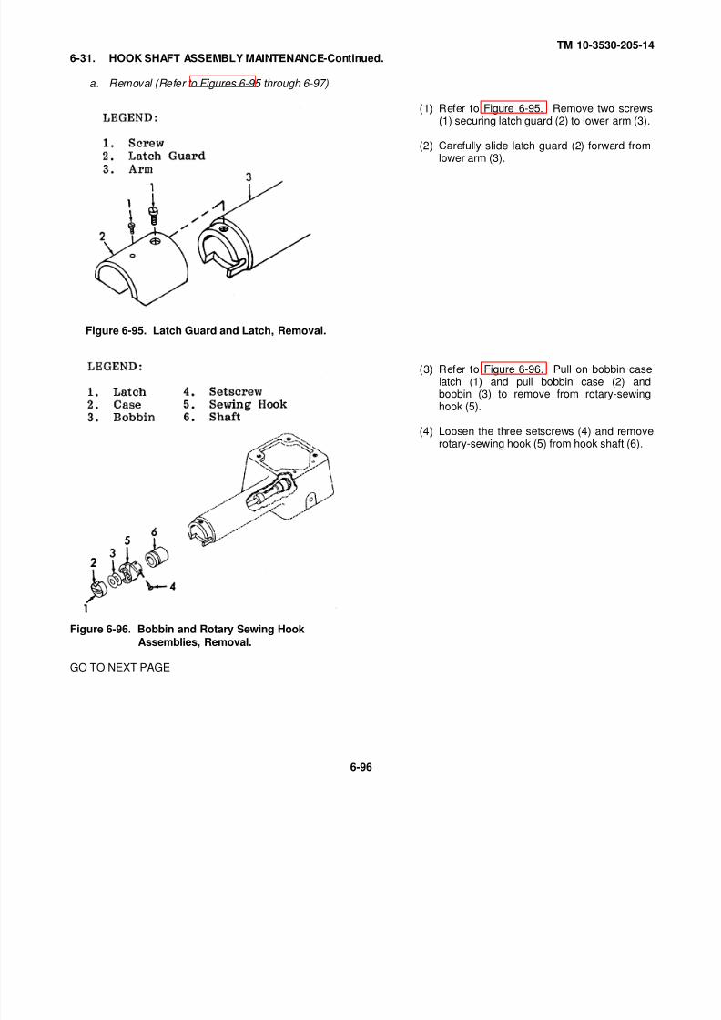
8/7/2019 TM 10-3530-205-10 CLOTHING REPAIR SHOP
http://slidepdf.com/reader/full/tm-10-3530-205-10-clothing-repair-shop 318/455
TM 10-3530-205-146-31. HOOK SHAFT ASSEMBLY MAINTENANCE-Continued.
a. Removal (Refer t o Figures 6-95 through 6-97).
Figure 6-95. Latch Guard and Latch, Removal.
Figure 6-96. Bobbin and Rotary Sewing HookAssemblies, Removal.
(1) Refer to Figure 6-95. Remove two screws(1) securing latch guard (2) to lower arm (3).
(2) Carefully slide latch guard (2) forward fromlower arm (3).
(3) Refer to Figure 6-96. Pull on bobbin caselatch (1) and pull bobbin case (2) andbobbin (3) to remove from rotary-sewinghook (5).
(4) Loosen the three setscrews (4) and removerotary-sewing hook (5) from hook shaft (6).
GO TO NEXT PAGE
6-96
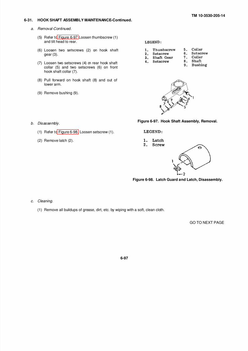
8/7/2019 TM 10-3530-205-10 CLOTHING REPAIR SHOP
http://slidepdf.com/reader/full/tm-10-3530-205-10-clothing-repair-shop 319/455
TM 10-3530-205-146-31. HOOK SHAFT ASSEMBLY MAINTENANCE-Continued.
a. Removal-Continued.
(5) Refer to Figure 6-97 Loosen thumbscrew (1)and tilt head to rear.
(6) Loosen two setscrews (2) on hook shaftgear (3).
(7) Loosen two setscrews (4) on rear hook shaftcollar (5) and two setscrews (6) on fronthook shaft collar (7).
(8) Pull forward on hook shaft (8) and out oflower arm.
(9) Remove bushing (9).
b. Disassembly.
(1) Refer to Figure 6-98. Loosen setscrew (1).
(2) Remove latch (2).
Figure 6-97. Hook Shaft Assembly, Removal.
Figure 6-98. Latch Guard and Latch, Disassembly.
c. Cleaning.
(1) Remove all buildups of grease, dirt, etc. by wiping with a soft, clean cloth.
GO TO NEXT PAGE
6-97
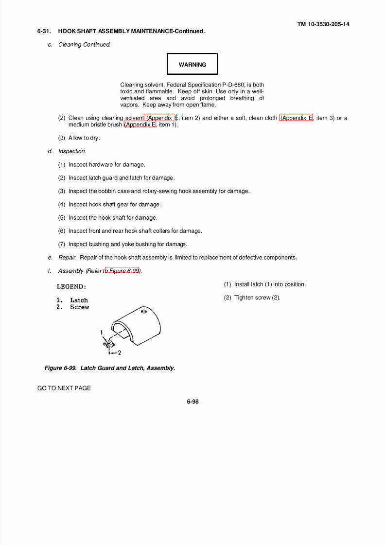
8/7/2019 TM 10-3530-205-10 CLOTHING REPAIR SHOP
http://slidepdf.com/reader/full/tm-10-3530-205-10-clothing-repair-shop 320/455
TM 10-3530-205-146-31. HOOK SHAFT ASSEMBLY MAINTENANCE-Continued.
c. Cleaning-Continued.
WARNING
Cleaning solvent, Federal Specification P-D-680, is bothtoxic and flammable. Keep off skin. Use only in a well-ventilated area and avoid prolonged breathing ofvapors. Keep away from open flame.
(2) Clean using cleaning solvent (Appendix E , item 2) and either a soft, clean cloth (Appendix E , item 3) or amedium bristle brush (Appendix E, item 1).
(3) Allow to dry.
d. Inspection.
(1) Inspect hardware for damage.
(2) Inspect latch guard and latch for damage.
(3) Inspect the bobbin case and rotary-sewing hook assembly for damage.
(4) Inspect hook shaft gear for damage.
(5) Inspect the hook shaft for damage.
(6) Inspect front and rear hook shaft collars for damage.
(7) Inspect bushing and yoke bushing for damage.
e. Repair. Repair of the hook shaft assembly is limited to replacement of defective components.
f. Assembly (Refer to Figure 6-99) .
Figure 6-99. Latch Guard and Latch, Assembly.
(1) Install latch (1) into position.
(2) Tighten screw (2).
GO TO NEXT PAGE
6-98
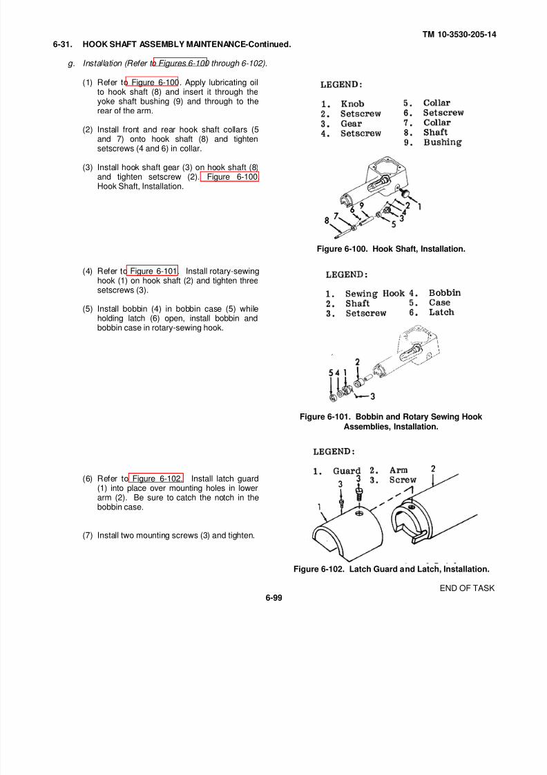
8/7/2019 TM 10-3530-205-10 CLOTHING REPAIR SHOP
http://slidepdf.com/reader/full/tm-10-3530-205-10-clothing-repair-shop 321/455
TM 10-3530-205-146-31. HOOK SHAFT ASSEMBLY MAINTENANCE-Continued.
g. Installation (Refer to Figures 6-100 through 6-102).
(1) Refer to Figure 6-100 . Apply lubricating oilto hook shaft (8) and insert it through theyoke shaft bushing (9) and through to therear of the arm.
(2) Install front and rear hook shaft collars (5and 7) onto hook shaft (8) and tightensetscrews (4 and 6) in collar.
(3) Install hook shaft gear (3) on hook shaft (8)and tighten setscrew (2). Figure 6-100.Hook Shaft, Installation.
(4) Refer to Figure 6-101. Install rotary-sewinghook (1) on hook shaft (2) and tighten threesetscrews (3).
(5) Install bobbin (4) in bobbin case (5) whileholding latch (6) open, install bobbin andbobbin case in rotary-sewing hook.
(6) Refer to Figure 6-102. Install latch guard(1) into place over mounting holes in lower
arm (2). Be sure to catch the notch in thebobbin case.
(7) Install two mounting screws (3) and tighten.
Figure 6-100. Hook Shaft, Installation.
Figure 6-101. Bobbin and Rotary Sewing HookAssemblies, Installation.
Figure 6-102. Latch Guard and Latch, Installation.
END OF TASK6-99
8/7/2019 TM 10-3530-205-10 CLOTHING REPAIR SHOP
http://slidepdf.com/reader/full/tm-10-3530-205-10-clothing-repair-shop 322/455
TM 10-3530-205-14
6-32. VERTICAL SHAFT ASSEMBLY MAINTENANCE.
This task covers:a. Removal b. Cleaning c. Inspection d. Repaire. Installation
INITIAL SETUP
EquipmentApplicable Configuration ConditionAll Para. Condition Description
2-13 Electrical powerremoved.
Test Equipment 2-13 Thread and needleNone removed.
6-31 Hook shaft removed.Special Tools
None Special Environmental ConditionsNone
Materials/PartsCleaning Solvent Personnel Required
(Appendix E , item 2) 1 PersonCloth, Soft, Lint-Free
(Appendix E , item 3)Brush, Medium Bristle
(Appendix E , item 1)
General Safety Instructions
WARNING
Cleaning solvent, Federal Specification P-D-680, is bothtoxic and flammable. Keep off skin. Use only in a well-ventilated area and avoid prolonged breathing ofvapors. Keep away from open flame.
GO TO NEXT PAGE
6-100
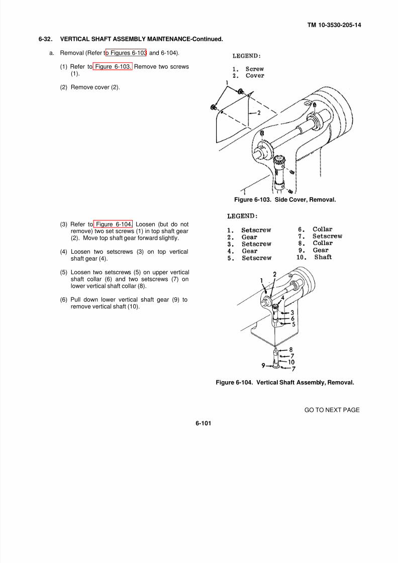
8/7/2019 TM 10-3530-205-10 CLOTHING REPAIR SHOP
http://slidepdf.com/reader/full/tm-10-3530-205-10-clothing-repair-shop 323/455
TM 10-3530-205-14
6-32. VERTICAL SHAFT ASSEMBLY MAINTENANCE-Continued.
a. Removal (Refer t o Figures 6-103 and 6-104).
(1) Refer to Figure 6-103. Remove two screws(1).
(2) Remove cover (2).
(3) Refer to Figure 6-104. Loosen (but do notremove) two set screws (1) in top shaft gear(2). Move top shaft gear forward slightly.
(4) Loosen two setscrews (3) on top verticalshaft gear (4).
(5) Loosen two setscrews (5) on upper verticalshaft collar (6) and two setscrews (7) onlower vertical shaft collar (8).
(6) Pull down lower vertical shaft gear (9) toremove vertical shaft (10).
Figure 6-103. Side Cover, Removal.
Figure 6-104. Vertical Shaft Assembly, Removal.
GO TO NEXT PAGE
6-101
8/7/2019 TM 10-3530-205-10 CLOTHING REPAIR SHOP
http://slidepdf.com/reader/full/tm-10-3530-205-10-clothing-repair-shop 324/455
TM 10-3530-205-14
6-32. VERTICAL SHAFT ASSEMBLY MAINTENANCE-Continued.
b. Cleaning.
(1) Remove all buildups of grease, dirt, etc. by wiping with a soft, clean cloth.
WARNING
Cleaning solvent, Federal Specification P-D-680, is bothtoxic and flammable. Keep off skin. Use only in a well-ventilated area and avoid prolonged breathing ofvapors. Keep away from open flame.
(2) Clean using cleaning solvent (Appendix D , item 2) and either a soft, clean cloth (Appendix E , item 3) or amedium bristle brush (Appendix E, item 1).
(3) Allow to dry.
c. Inspection.
(1) Inspect hardware for damage.
(2) Inspect side cover for damage.
(3) Inspect upper and lower vertical shaft gears for damage.
(4) Inspect shaft collars for damage.
(5) Inspect vertical shaft for damage.
d. Repair. Repair is limited to replacement of defective components.
GO TO NEXT PAGE
6-102
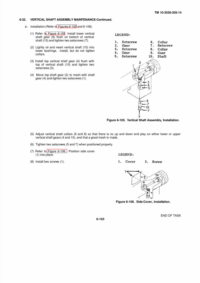
8/7/2019 TM 10-3530-205-10 CLOTHING REPAIR SHOP
http://slidepdf.com/reader/full/tm-10-3530-205-10-clothing-repair-shop 325/455
TM 10-3530-205-14
6-32. VERTICAL SHAFT ASSEMBLY MAINTENANCE-Continued.
e.. Installation (Refer to Figures 6-105 and 6-106).
(1) Refer to Figure 6-105 . Install lower verticalshaft gear (9) flush on bottom of verticalshaft (10) and tighten two setscrews (7).
(2) Lightly oil and insert vertical shaft (10) intolower bushings. Install, but do not tightencollars.
(3) Install top vertical shaft gear (4) flush withtop of vertical shaft (10) and tighten twosetscrews (3).
(4) Move top shaft gear (2) to mesh with shaftgear (4) and tighten two setscrews (1).
Figure 6-105. Vertical Shaft Assembly, Installation.
(5) Adjust vertical shaft collars (6 and 8) so that there is no up and down end play on either lower or uppervertical shaft gears (4 and 10), and that a good mesh is made.
(6) Tighten two setscrews (5 and 7) when positioned properly.
(7) Refer to Figure 6-106. Position side cover(1) into place.
(8) Install two screws (1).
Figure 6-106. Side Cover, Installation.
END OF TASK6-103
8/7/2019 TM 10-3530-205-10 CLOTHING REPAIR SHOP
http://slidepdf.com/reader/full/tm-10-3530-205-10-clothing-repair-shop 326/455
TM 10-3530-205-14
6-33. NEEDLE BAR AND PRESSER BAR ASSEMBLY MAINTENANCE.
This task covers:a. Removal b. Cleaning c. Inspection d. Repaire. Installation
INITIAL SETUP
EquipmentApplicable Configuration ConditionAll Para. Condition Description
2-13 Electrical powerremoved.
Test Equipment 2-13 Thread and needleNone removed.
Special ToolsNone Special Environmental Conditions
NoneMaterials/PartsCleaning Solvent Personnel Required
(Appendix E , item 2) 1 PersonCloth, Soft, Lint-Free
(Appendix E , item 3)Brush, Medium Bristle
(Appendix E , item 1)
General Safety Instructions
WARNING
Cleaning solvent, Federal Specification P-D-680, is bothtoxic and flammable. Keep off skin. Use only in a well-ventilated area and avoid prolonged breathing ofvapors. Keep away from open flame.
GO TO NEXT PAGE
6-104
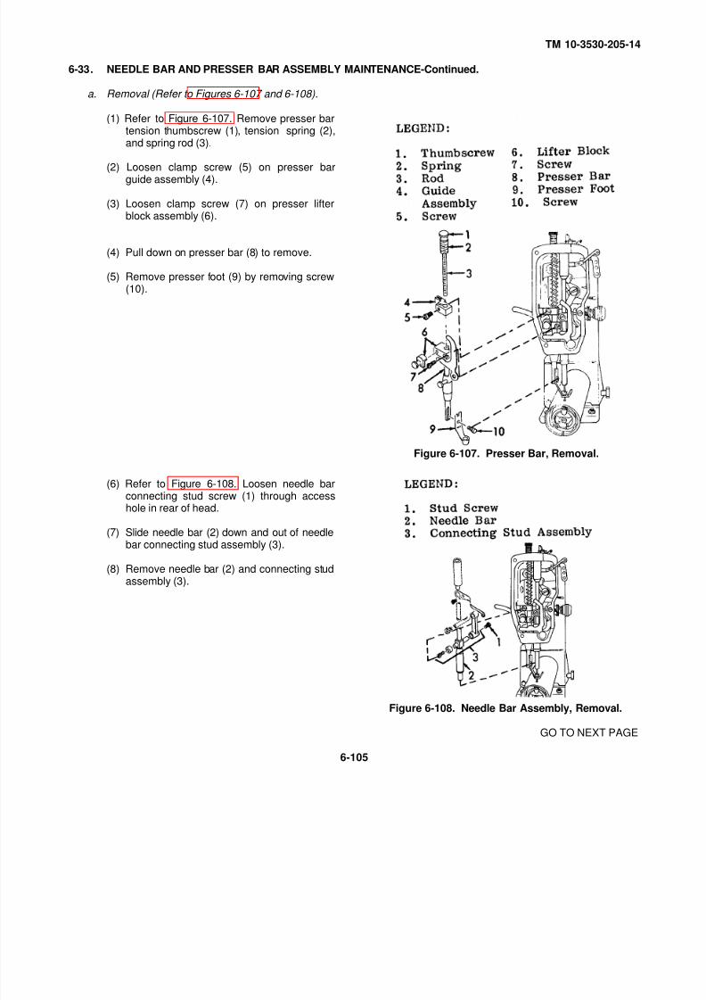
8/7/2019 TM 10-3530-205-10 CLOTHING REPAIR SHOP
http://slidepdf.com/reader/full/tm-10-3530-205-10-clothing-repair-shop 327/455
TM 10-3530-205-14
6-33. NEEDLE BAR AND PRESSER BAR ASSEMBLY MAINTENANCE-Continued.
a. Removal (Refer t o Figures 6-107 and 6-108).
(1) Refer to Figure 6-107. Remove presser bartension thumbscrew (1), tension spring (2),and spring rod (3).
(2) Loosen clamp screw (5) on presser barguide assembly (4).
(3) Loosen clamp screw (7) on presser lifterblock assembly (6).
(4) Pull down on presser bar (8) to remove.
(5) Remove presser foot (9) by removing screw(10).
(6) Refer to Figure 6-108. Loosen needle barconnecting stud screw (1) through accesshole in rear of head.
(7) Slide needle bar (2) down and out of needlebar connecting stud assembly (3).
(8) Remove needle bar (2) and connecting studassembly (3).
Figure 6-107. Presser Bar, Removal.
Figure 6-108. Needle Bar Assembly, Removal.
GO TO NEXT PAGE
6-105
8/7/2019 TM 10-3530-205-10 CLOTHING REPAIR SHOP
http://slidepdf.com/reader/full/tm-10-3530-205-10-clothing-repair-shop 328/455
TM 10-3530-205-14
6-33. NEEDLE BAR AND PRESSER BAR ASSEMBLY MAINTENANCE-Continued.
b. Cleaning.
(1) Remove all buildups of grease, dirt, etc. by wiping with a soft, clean cloth, without disassembling the presserbar guide or presser lifter block assemblies.
WARNING
Cleaning solvent, Federal Specification P-D-680, is bothtoxic and flammable. Keep off skin. Use only in a well-ventilated area and avoid prolonged breathing ofvapors. Keep away from open flame.
(2) Clean using cleaning solvent (Appendix D , item 2) and either a soft, clean cloth (Appendix E , item 3) or amedium bristle brush (Appendix E, item 1).
(3) Allow to dry.
c. Inspection.
(1) Inspect hardware for damage.
(2) Inspect presser bar and foot for damage.
(3) Inspect presser bar guide assembly for damage.
(4) Inspect presser lifter block assembly for damage.
(5) Inspect tension spring for damage or weakness.
(6) Inspect needle bar for damage.
(7) Inspect needle bar connecting stud for damage.
d. Repair. Repair is limited to the replacement of defective components or assemblies.
GO TO NEXT PAGE
6-106
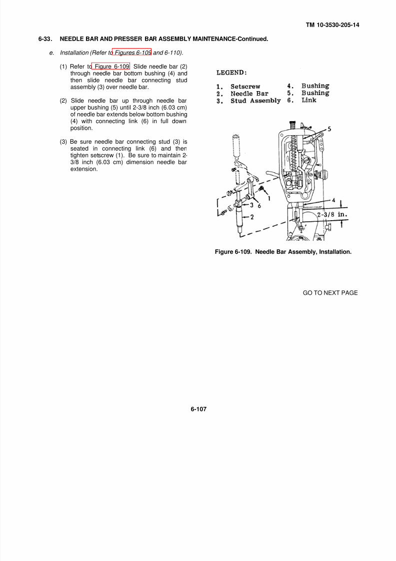
8/7/2019 TM 10-3530-205-10 CLOTHING REPAIR SHOP
http://slidepdf.com/reader/full/tm-10-3530-205-10-clothing-repair-shop 329/455
TM 10-3530-205-14
6-33. NEEDLE BAR AND PRESSER BAR ASSEMBLY MAINTENANCE-Continued.
e. Installation (Refer to Figures 6-109 and 6-110).
(1) Refer to Figure 6-109. Slide needle bar (2)through needle bar bottom bushing (4) andthen slide needle bar connecting studassembly (3) over needle bar.
(2) Slide needle bar up through needle barupper bushing (5) until 2-3/8 inch (6.03 cm)of needle bar extends below bottom bushing(4) with connecting link (6) in full downposition.
(3) Be sure needle bar connecting stud (3) isseated in connecting link (6) and thentighten setscrew (1). Be sure to maintain 2-3/8 inch (6.03 cm) dimension needle barextension.
Figure 6-109. Needle Bar Assembly, Installation.
GO TO NEXT PAGE
6-107
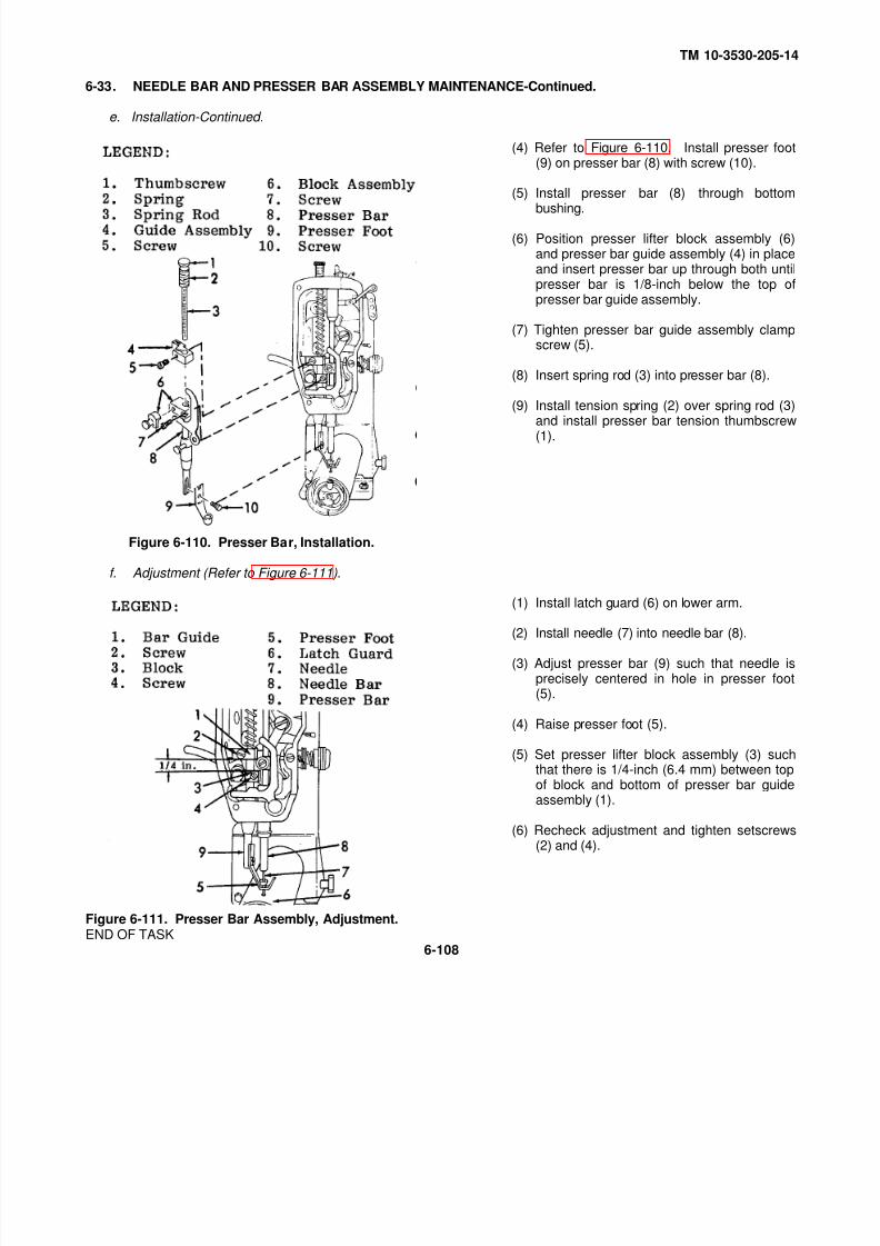
8/7/2019 TM 10-3530-205-10 CLOTHING REPAIR SHOP
http://slidepdf.com/reader/full/tm-10-3530-205-10-clothing-repair-shop 330/455
TM 10-3530-205-14
6-33. NEEDLE BAR AND PRESSER BAR ASSEMBLY MAINTENANCE-Continued.
e. Installation-Continued.
Figure 6-110. Presser Bar, Installation.
f. Adjustment (Refer to Figure 6-111) .
(4) Refer to Figure 6-110. Install presser foot(9) on presser bar (8) with screw (10).
(5) Install presser bar (8) through bottombushing.
(6) Position presser lifter block assembly (6)and presser bar guide assembly (4) in placeand insert presser bar up through both untilpresser bar is 1/8-inch below the top ofpresser bar guide assembly.
(7) Tighten presser bar guide assembly clampscrew (5).
(8) Insert spring rod (3) into presser bar (8).
(9) Install tension spring (2) over spring rod (3)and install presser bar tension thumbscrew(1).
(1) Install latch guard (6) on lower arm.
(2) Install needle (7) into needle bar (8).
(3) Adjust presser bar (9) such that needle isprecisely centered in hole in presser foot(5).
(4) Raise presser foot (5).
(5) Set presser lifter block assembly (3) suchthat there is 1/4-inch (6.4 mm) between topof block and bottom of presser bar guide
assembly (1).(6) Recheck adjustment and tighten setscrews
(2) and (4).
Figure 6-111. Presser Bar Assembly, Adjustment.END OF TASK
6-108
8/7/2019 TM 10-3530-205-10 CLOTHING REPAIR SHOP
http://slidepdf.com/reader/full/tm-10-3530-205-10-clothing-repair-shop 331/455
TM 10-3530-205-14
6-34. PULLEY MAINTENANCE.
This task covers:a. Removal b. Cleaning c. Inspection d. Repaire. Installation
INITIAL SETUP
EquipmentApplicable Configuration ConditionAll Para. Condition Description
2-13 Electrical powerremoved.
Test Equipment 2-9 Drive belts removed.None
Special ToolsNone Special Environmental Conditions
NoneMaterials/PartsCleaning Solvent Personnel Required
(Appendix E , item 2) 1 PersonCloth, Soft, Lint-Free
(Appendix E , item 3)Brush, Medium Bristle
(Appendix E , item 1)
General Safety Instructions
WARNING
Cleaning solvent, Federal Specification P-D-680, is bothtoxic and flammable. Keep off skin. Use only in a well-ventilated area and avoid prolonged breathing ofvapors. Keep away from open flame.
GO TO NEXT PAGE
6-109
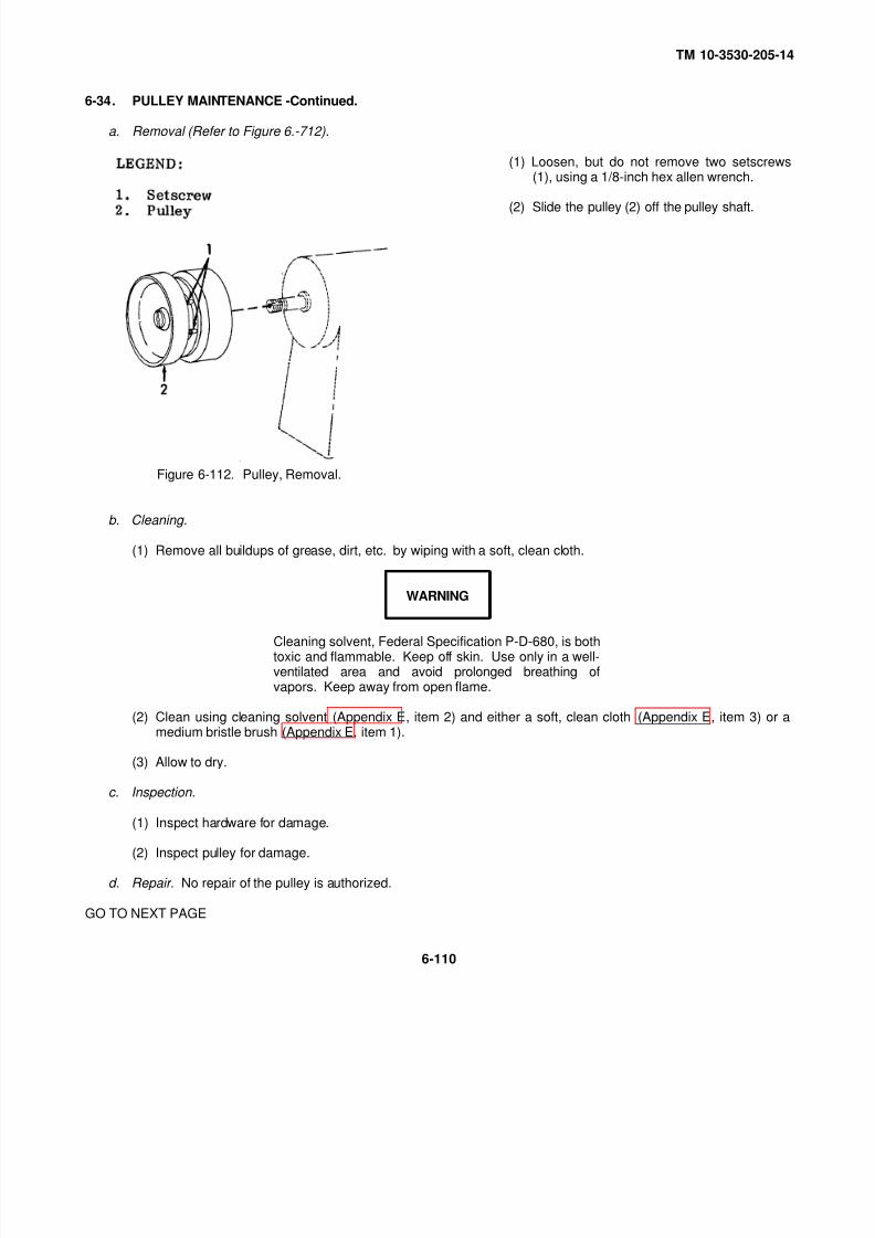
8/7/2019 TM 10-3530-205-10 CLOTHING REPAIR SHOP
http://slidepdf.com/reader/full/tm-10-3530-205-10-clothing-repair-shop 332/455
TM 10-3530-205-14
6-34. PULLEY MAINTENANCE -Continued.
a. Removal (Refer to Figure 6.-712).
Figure 6-112. Pulley, Removal.
(1) Loosen, but do not remove two setscrews(1), using a 1/8-inch hex allen wrench.
(2) Slide the pulley (2) off the pulley shaft.
b. Cleaning.
(1) Remove all buildups of grease, dirt, etc. by wiping with a soft, clean cloth.
WARNING
Cleaning solvent, Federal Specification P-D-680, is bothtoxic and flammable. Keep off skin. Use only in a well-ventilated area and avoid prolonged breathing ofvapors. Keep away from open flame.
(2) Clean using cleaning solvent (Appendix E , item 2) and either a soft, clean cloth (Appendix E , item 3) or amedium bristle brush (Appendix E, item 1).
(3) Allow to dry.
c. Inspection.(1) Inspect hardware for damage.
(2) Inspect pulley for damage.
d. Repair . No repair of the pulley is authorized.
GO TO NEXT PAGE
6-110
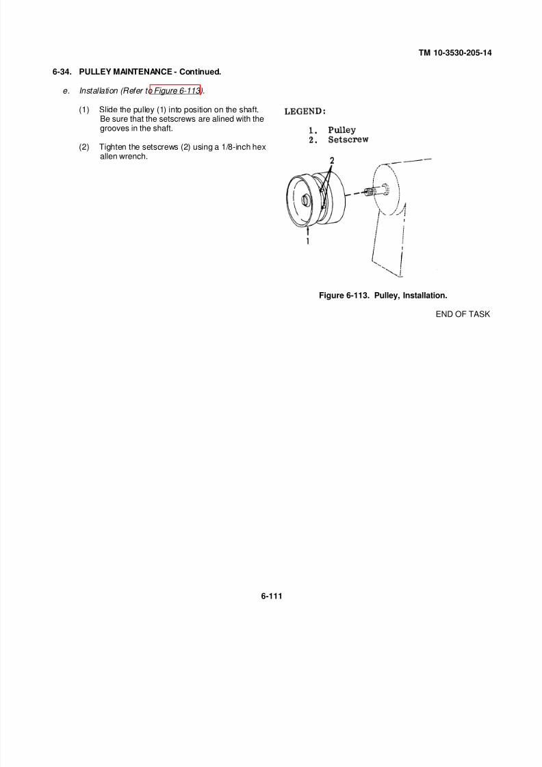
8/7/2019 TM 10-3530-205-10 CLOTHING REPAIR SHOP
http://slidepdf.com/reader/full/tm-10-3530-205-10-clothing-repair-shop 333/455
TM 10-3530-205-14
6-34. PULLEY MAINTENANCE - Continued.
e. Installation (Refer to Figure 6-113) .
(1) Slide the pulley (1) into position on the shaft.Be sure that the setscrews are alined with thegrooves in the shaft.
(2) Tighten the setscrews (2) using a 1/8-inch hexallen wrench.
Figure 6-113. Pulley, Installation.
END OF TASK
6-111
8/7/2019 TM 10-3530-205-10 CLOTHING REPAIR SHOP
http://slidepdf.com/reader/full/tm-10-3530-205-10-clothing-repair-shop 334/455
TM 10-3530-205-14
6-35. U PPER SHAFT ASSEMBLY MAINTENANCE.
This task covers:a. Removal b. Cleaning c. Inspection d. Repaire. Installation
INITIAL SETUP EquipmentConditionApplicable Configuration Para. Condition Description
All 2-13 Electrical powerremoved.
Test Equipment 6-32 Vertical shaft removed.None 6-33 Needle bar and presbar assembly
removed
Special Tools Special Environmental ConditionsNone None
Materials/Parts Personnel Required
Cleaning Solvent 1 Person(Appendix E , item 2)Cloth, Soft, Lint-Free
(Appendix E , item 3)Brush, Medium Bristle
(Appendix E, item 1)
General Safety Instructions
WARNING
Cleaning solvent, Federal Specification P-D-680, is both toxic and flammable. Keep off skin. Use only in a well-ventilated area and avoid
prolonged breathing of vapors. Keep away from open flame.
GO TO NEXT PAGE
6-112
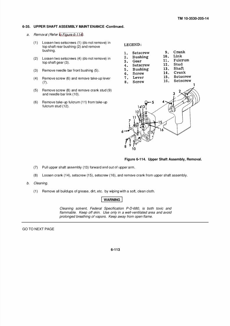
8/7/2019 TM 10-3530-205-10 CLOTHING REPAIR SHOP
http://slidepdf.com/reader/full/tm-10-3530-205-10-clothing-repair-shop 335/455
TM 10-3530-205-14
6-35. UPPER SHAFT ASSEMBLY MAINT ENANCE -Continued.
a. Removal (Refer t o Figure 6-114) .
(1) Loosen two setscrews (1) (do not remove) intop shaft rear bushing (2) and removebushing.
(2) Loosen two setscrews (4) (do not remove) intop shaft gear (3).
(3) Remove needle bar front bushing (5).
(4) Remove screw (6) and remove take-up lever(7).
(5) Remove screw (8) and remove crank stud (9)and needle bar link (10).
(6) Remove take-up fulcrum (11) from take-upfulcrum stud (12).
Figure 6-114. Upper Shaft Assembly, Removal.
(7) Pull upper shaft assembly (13) forward and out of upper arm.
(8) Loosen crank (14), setscrew (15), setscrew (16), and remove crank from upper shaft assembly.
b. Cleaning.
(1) Remove all buildups of grease, dirt, etc. by wiping with a soft, clean cloth.
WARNING
Cleaning solvent, Federal Specification P-D-680, is both toxic and flammable. Keep off skin. Use only in a well-ventilated area and avoid prolonged breathing of vapors. Keep away from open flame.
GO TO NEXT PAGE
6-113
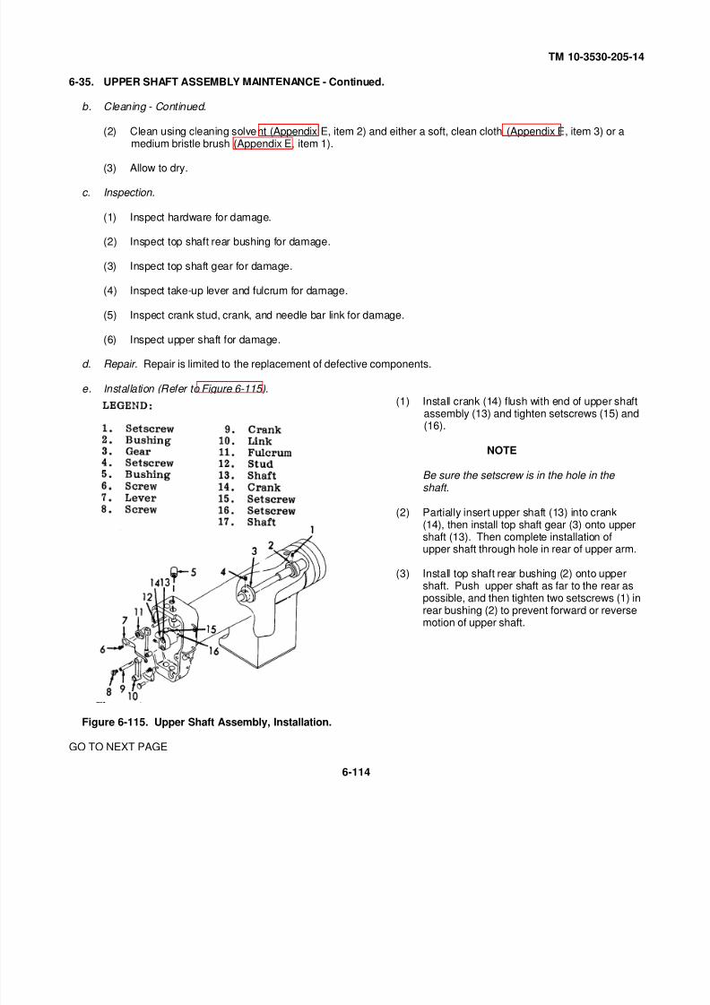
8/7/2019 TM 10-3530-205-10 CLOTHING REPAIR SHOP
http://slidepdf.com/reader/full/tm-10-3530-205-10-clothing-repair-shop 336/455
TM 10-3530-205-14
6-35. UPPER SHAFT ASSEMBLY MAINTENANCE - Continued.
b. Cleaning - Continued.
(2) Clean using cleaning solve nt (Appendix E, item 2) and either a soft, clean cloth (Appendix E , item 3) or amedium bristle brush (Appendix E, item 1).
(3) Allow to dry.
c. Inspection.
(1) Inspect hardware for damage.
(2) Inspect top shaft rear bushing for damage.
(3) Inspect top shaft gear for damage.
(4) Inspect take-up lever and fulcrum for damage.
(5) Inspect crank stud, crank, and needle bar link for damage.
(6) Inspect upper shaft for damage.
d. Repair. Repair is limited to the replacement of defective components.
e. Installation (Refer to Figure 6-115) .(1) Install crank (14) flush with end of upper shaft
assembly (13) and tighten setscrews (15) and(16).
NOTE
Be sure the setscrew is in the hole in the shaft.
(2) Partially insert upper shaft (13) into crank(14), then install top shaft gear (3) onto uppershaft (13). Then complete installation ofupper shaft through hole in rear of upper arm.
(3) Install top shaft rear bushing (2) onto uppershaft. Push upper shaft as far to the rear aspossible, and then tighten two setscrews (1) inrear bushing (2) to prevent forward or reversemotion of upper shaft.
Figure 6-115. Upper Shaft Assembly, Installation.
GO TO NEXT PAGE
6-114
8/7/2019 TM 10-3530-205-10 CLOTHING REPAIR SHOP
http://slidepdf.com/reader/full/tm-10-3530-205-10-clothing-repair-shop 337/455
TM 10-3530-205-14
6-35. UPPER SHAFT ASSEMBLY MAINTENANCE -Continued.
e. Installation - Continued.
(4) Install take-up lever fulcrum (11) and secure with take-up fulcrum stud (12).
(5) Install needle bar link (10) and install into position with crank stud (9) and screw (8).
(6) Install take-up lever (7) and secure with screw (6).
(7) Install needle bar front bushing (5) with flat to rear.
END OF TASK
6-36. M ACHINE TIMING.
This task covers:
Machine Timing
INITIAL SETUP EquipmentCondition
Applicable Configuration Para. Condition DescriptionAll 2-13 Electrical power removed.
6-30 Face plate removed.Test Equipment 6-31 Latch guard removed.
NoneSpecial Environmental Conditions
Special Tools NoneNone
General Safety Instructions
Materials/Parts NoneNone
Personnel Required1 Person
GO TO NEXT PAGE
6-115
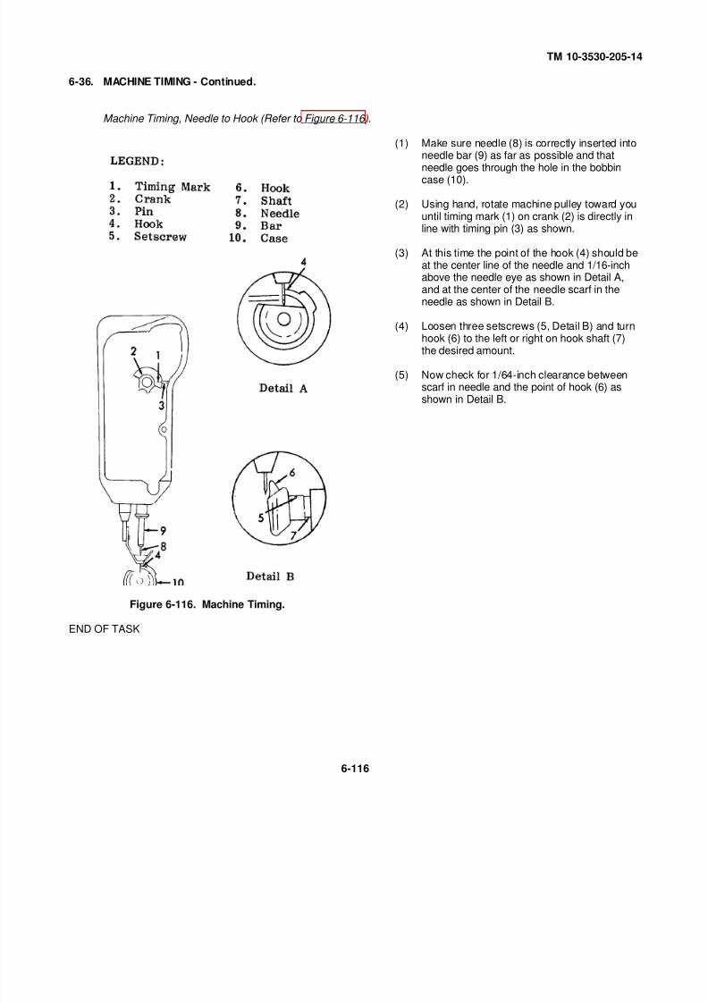
8/7/2019 TM 10-3530-205-10 CLOTHING REPAIR SHOP
http://slidepdf.com/reader/full/tm-10-3530-205-10-clothing-repair-shop 338/455
TM 10-3530-205-14
6-36. MACHINE TIMING - Continued.
Machine Timing, Needle to Hook (Refer to Figure 6-116) .
(1) Make sure needle (8) is correctly inserted intoneedle bar (9) as far as possible and thatneedle goes through the hole in the bobbincase (10).
(2) Using hand, rotate machine pulley toward youuntil timing mark (1) on crank (2) is directly inline with timing pin (3) as shown.
(3) At this time the point of the hook (4) should beat the center line of the needle and 1/16-inchabove the needle eye as shown in Detail A,and at the center of the needle scarf in theneedle as shown in Detail B.
(4) Loosen three setscrews (5, Detail B) and turnhook (6) to the left or right on hook shaft (7)the desired amount.
(5) Now check for 1/64-inch clearance betweenscarf in needle and the point of hook (6) asshown in Detail B.
Figure 6-116. Machine Timing.
END OF TASK
6-116
8/7/2019 TM 10-3530-205-10 CLOTHING REPAIR SHOP
http://slidepdf.com/reader/full/tm-10-3530-205-10-clothing-repair-shop 339/455
TM 10-3530-205-14
6-37. E LECTRIC MOTOR MAINTENANCE.
For maintenance of the electric motor, refer to paragraph 6-27.
SECTION V. MAINTENANCE OF BUTTON SEWING MACHINEPara. Para.
Automatic Thread LockingMechanism Maintenance................................ ......... .....6-45Button Clamp Maintenance................................ ...... ....6-41Clamp Lift and Thread Slack Mechanism
Maintenance................................ ..................... ..... 6-44Electric Motor Maintenance................................ ..... .....6-50Face Plate Maintenance................................ .......... .....6-40Foot Treadle Lever Assemblies Maintenance .......... .... 6-42General................................ ................................ ... .....6-38Looper and Finger Mechanism Maintenance............ .... 6-46
Machine Timing................................ ........................ ... 6-49Needle Bar Drive Mechanism
Maintenance................................ .................... .... 6-43Stitch Adjustment Mechanism
Maintenance................................ .................... ... 6-47Stopping Mechanism Maintenance........................... ... 6-48Storage Box Assembly
Maintenance................................ .................... .... 6-51Thread Tensioner and Thread Guide
Maintenance................................ ...................... .... 6-39
6-38. G ENERAL.
This section contains information on the removal, disassembly, cleaning, inspection, repair, assembly, installation, andadjustment of the various parts of the button sewing machine.
6-117
8/7/2019 TM 10-3530-205-10 CLOTHING REPAIR SHOP
http://slidepdf.com/reader/full/tm-10-3530-205-10-clothing-repair-shop 340/455
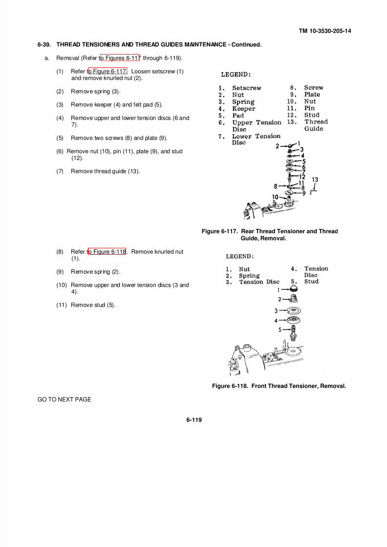
8/7/2019 TM 10-3530-205-10 CLOTHING REPAIR SHOP
http://slidepdf.com/reader/full/tm-10-3530-205-10-clothing-repair-shop 341/455
TM 10-3530-205-14
6-39. THREAD TENSIONERS AND THREAD GUIDES MAINTENANCE - Continued.
a. Removal (Refer t o Figures 6-117 through 6-119).
(1) Refer t o Figure 6-117. Loosen setscrew (1)and remove knurled nut (2).
(2) Remove spring (3).
(3) Remove keeper (4) and felt pad (5).
(4) Remove upper and lower tension discs (6 and7).
(5) Remove two screws (8) and plate (9).
(6) Remove nut (10), pin (11), plate (9), and stud(12).
(7) Remove thread guide (13).
Figure 6-117. Rear Thread Tensioner and ThreadGuide, Removal.
(8) Refer t o Figure 6-118 . Remove knurled nut(1).
(9) Remove spring (2).
(10) Remove upper and lower tension discs (3 and4).
(11) Remove stud (5).
Figure 6-118. Front Thread Tensioner, Removal.
GO TO NEXT PAGE
6-119
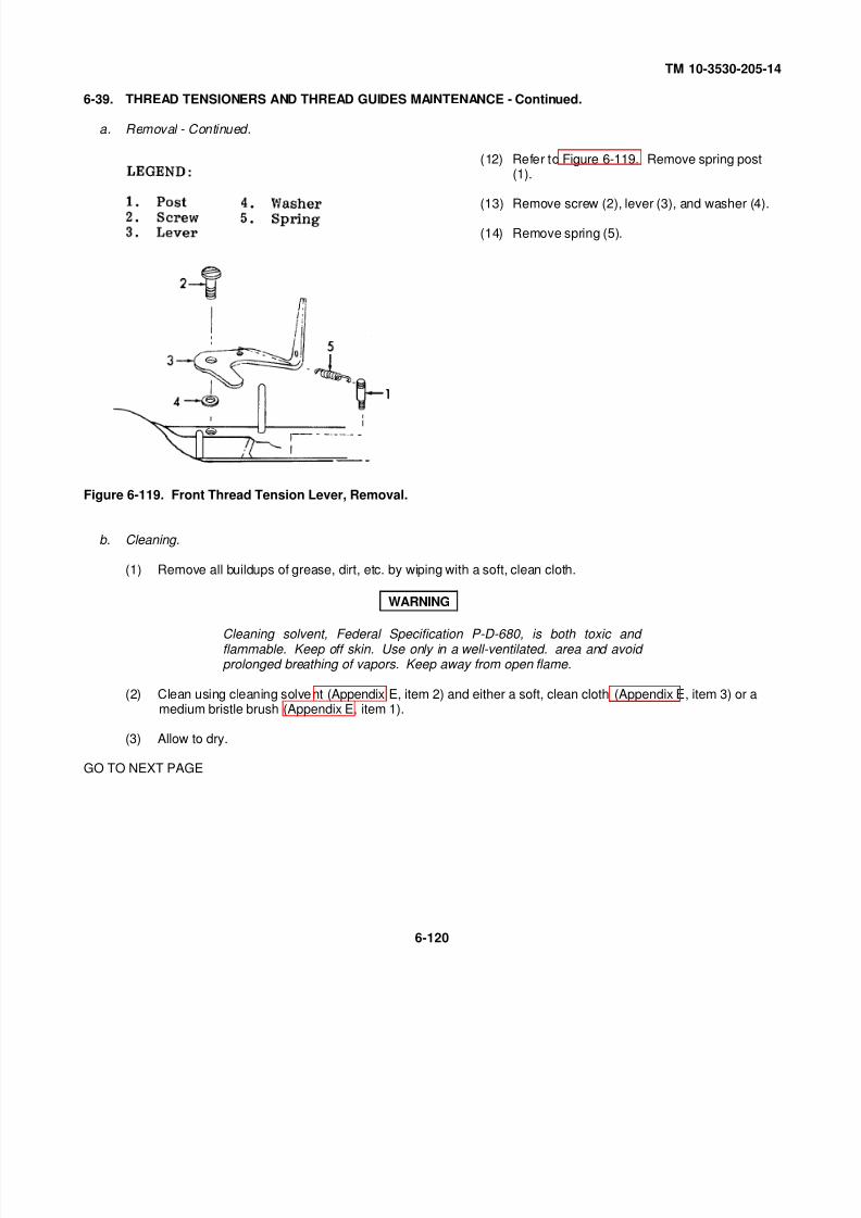
8/7/2019 TM 10-3530-205-10 CLOTHING REPAIR SHOP
http://slidepdf.com/reader/full/tm-10-3530-205-10-clothing-repair-shop 342/455
TM 10-3530-205-14
6-39. THREAD TENSIONERS AND THREAD GUIDES MAINTENANCE - Continued.
a. Removal - Continued.
(12) Refer to Figure 6-119. Remove spring post(1).
(13) Remove screw (2), lever (3), and washer (4).
(14) Remove spring (5).
Figure 6-119. Front Thread Tension Lever, Removal.
b. Cleaning.
(1) Remove all buildups of grease, dirt, etc. by wiping with a soft, clean cloth.
WARNING
Cleaning solvent, Federal Specification P-D-680, is both toxic and flammable. Keep off skin. Use only in a well-ventilated. area and avoid prolonged breathing of vapors. Keep away from open flame.
(2) Clean using cleaning solve nt (Appendix E, item 2) and either a soft, clean cloth (Appendix E , item 3) or amedium bristle brush (Appendix E, item 1).
(3) Allow to dry.
GO TO NEXT PAGE
6-120
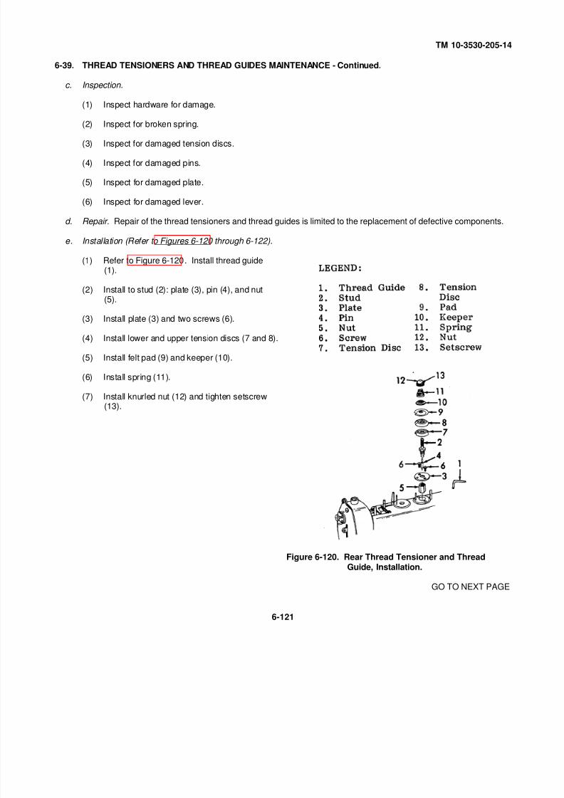
8/7/2019 TM 10-3530-205-10 CLOTHING REPAIR SHOP
http://slidepdf.com/reader/full/tm-10-3530-205-10-clothing-repair-shop 343/455
TM 10-3530-205-14
6-39. THREAD TENSIONERS AND THREAD GUIDES MAINTENANCE - Continued.
c. Inspection.
(1) Inspect hardware for damage.
(2) Inspect for broken spring.(3) Inspect for damaged tension discs.
(4) Inspect for damaged pins.
(5) Inspect for damaged plate.
(6) Inspect for damaged lever.
d. Repair. Repair of the thread tensioners and thread guides is limited to the replacement of defective components.
e. Installation (Refer t o Figures 6-120 through 6-122).
(1) Refer t o Figure 6-120 . Install thread guide(1).
(2) Install to stud (2): plate (3), pin (4), and nut(5).
(3) Install plate (3) and two screws (6).
(4) Install lower and upper tension discs (7 and 8).
(5) Install felt pad (9) and keeper (10).
(6) Install spring (11).
(7) Install knurled nut (12) and tighten setscrew(13).
Figure 6-120. Rear Thread Tensioner and ThreadGuide, Installation.
GO TO NEXT PAGE
6-121
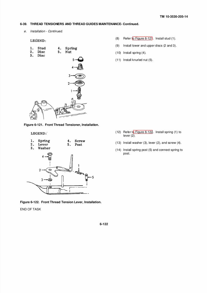
8/7/2019 TM 10-3530-205-10 CLOTHING REPAIR SHOP
http://slidepdf.com/reader/full/tm-10-3530-205-10-clothing-repair-shop 344/455
TM 10-3530-205-14
6-39. THREAD TENSIONERS AND THREAD GUIDES MAINTENANCE- Continued.
e. Installation - Continued.
(8) Refer t o Figure 6-121 . Install stud (1).
(9) Install lower and upper discs (2 and 3).(10) Install spring (4).
(11) Install knurled nut (5).
Figure 6-121. Front Thread Tensioner, Installation.
(12) Refer t o Figure 6-122 . Install spring (1) tolever (2).
(13) Install washer (3), lever (2), and screw (4).
(14) Install spring post (5) and connect spring topost.
Figure 6-122. Front Thread Tension Lever, Installation.
END OF TASK
6-122
8/7/2019 TM 10-3530-205-10 CLOTHING REPAIR SHOP
http://slidepdf.com/reader/full/tm-10-3530-205-10-clothing-repair-shop 345/455
TM 10-3530-205-14
6-40. F ACE PLATE MAINTENANCE.
This task covers:a. Removal b. Disassembly c. Cleaning d. Inspectione. Repair f. Assembly g. Installation
INITIAL SETUP EquipmentConditionApplicable Configuration Para. Condition Description
All 2-9 Electrical powerremoved.
Test Equipment 2-14 Thread and needleNone removed.
Special Tools Special Environmental ConditionsNone None
Materials/Parts Personnel RequiredCleaning Solvent 1 Person
(Appendix E , item 2)Cloth, Soft, Lint-Free(Appendix E , item 3)
Brush, Medium Bristle(Appendix E, item 1)
General Safety Instructions
WARNING
Cleaning solvent, Federal Specification P-D-680, is both toxic and flammable. Keep off skin. Use only in a well-ventilated area and avoid prolonged breathing of vapors. Keep away from open flame.
GO TO NEXT PAGE
6-123
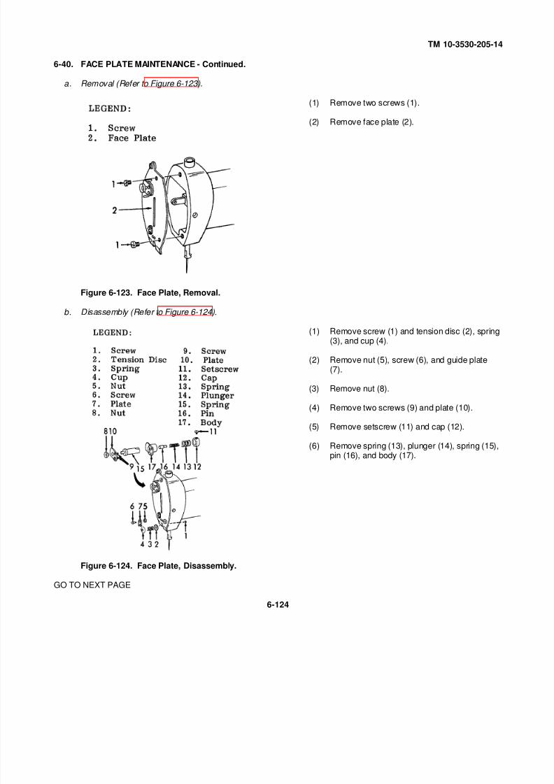
8/7/2019 TM 10-3530-205-10 CLOTHING REPAIR SHOP
http://slidepdf.com/reader/full/tm-10-3530-205-10-clothing-repair-shop 346/455
TM 10-3530-205-14
6-40. FACE PLATE MAINTENANCE - Continued.
a. Removal (Refer t o Figure 6-123) .
(1) Remove two screws (1).
(2) Remove face plate (2).
Figure 6-123. Face Plate, Removal.
b. Disassembly (Refer t o Figure 6-124) .
(1) Remove screw (1) and tension disc (2), spring(3), and cup (4).
(2) Remove nut (5), screw (6), and guide plate(7).
(3) Remove nut (8).
(4) Remove two screws (9) and plate (10).
(5) Remove setscrew (11) and cap (12).
(6) Remove spring (13), plunger (14), spring (15),pin (16), and body (17).
Figure 6-124. Face Plate, Disassembly.
GO TO NEXT PAGE
6-124
8/7/2019 TM 10-3530-205-10 CLOTHING REPAIR SHOP
http://slidepdf.com/reader/full/tm-10-3530-205-10-clothing-repair-shop 347/455
TM 10-3530-205-14
6-40. FACE PLATE MAINTENANCE - Continued.
c. Cleaning.
(1) Remove all buildups of grease, dirt, etc. by wiping with a soft, clean cloth.
WARNING
Cleaning solvent, Federal Specification P-D-680, is both toxic and flammable. Keep off skin. Use only in a well-ventilated area and avoid prolonged breathing of vapors. Keep away from open flame.
(2) Clean using cleaning solve nt (Appendix E, item 2) and either a soft, clean cloth (Appendix E , item 3) or amedium bristle brush (Appendix E, item 1).
(3) Allow to dry.
d. Inspection.
(1) Inspect for damaged hardware.(2) Inspect for damaged face plate.
(3) Inspect for damaged tension disc.
(4) Inspect for damaged springs.
(5) Inspect for damaged plunger and pins.
e. Repair . Repair of the face plate is limited to the replacement of defective components.
GO TO NEXT PAGE
6-125
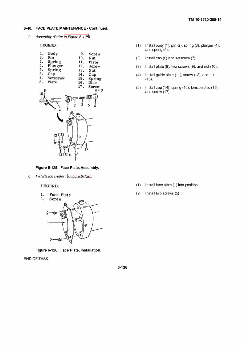
8/7/2019 TM 10-3530-205-10 CLOTHING REPAIR SHOP
http://slidepdf.com/reader/full/tm-10-3530-205-10-clothing-repair-shop 348/455
TM 10-3530-205-14
6-40. FACE PLATE MAINTENANCE - Continued.
f. Assembly (Refer t o Figure 6-125) .
(1) Install body (1), pin (2), spring (3), plunger (4),and spring (5).
(2) Install cap (6) and setscrew (7).
(3) Install plate (8), two screws (9), and nut (10).
(4) Install guide plate (11), screw (12), and nut(13).
(5) Install cup (14), spring (15), tension disc (16),and screw (17).
Figure 6-125. Face Plate, Assembly.
g. Installation (Refer to Figure 6-126) .
(1) Install face plate (1) into position.
(2) Install two screws (2).
Figure 6-126. Face Plate, Installation.
END OF TASK
6-126
8/7/2019 TM 10-3530-205-10 CLOTHING REPAIR SHOP
http://slidepdf.com/reader/full/tm-10-3530-205-10-clothing-repair-shop 349/455
TM 10-3530-205-14
6-41. BUTTON CLAMP MAINTENANCE.
This task covers:a. Removal b. Cleaning c. Inspection d. Repaire. Installation
INITIAL SETUP EquipmentConditionApplicable Configuration Para. Condition Description
All 2-9 Electrical powerremoved.
Test Equipment 2-14 Thread and needleNone removed.
Special Tools Special Environmental ConditionsNone None
Materials/Parts Personnel RequiredCleaning Solvent 1 Person
(Appendix E , item 2)Cloth, Soft, Lint-Free(Appendix E , item 3)
Brush, Medium Bristle(Appendix E, item 1)
General Safety Instructions
WARNING
Cleaning solvent, Federal Specification P-D-680, is both toxic and flammable. Keep off skin. Use only in a well-ventilated area and avoid prolonged breathing of vapors. Keep away from open flame.
GO TO NEXT PAGE
Change 1 6-127
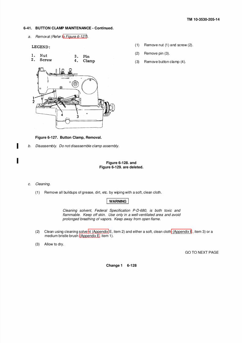
8/7/2019 TM 10-3530-205-10 CLOTHING REPAIR SHOP
http://slidepdf.com/reader/full/tm-10-3530-205-10-clothing-repair-shop 350/455
TM 10-3530-205-14
6-41. BUTTON CLAMP MAINTENANCE - Continued.
a. Removal (Refer t o Figure 6-127) .
(1) Remove nut (1) and screw (2).
(2) Remove pin (3).(3) Remove button clamp (4).
Figure 6-127. Button Clamp, Removal.
b. Disassembly. Do not disassemble clamp assembly.
Figure 6-128. andFigure 6-129. are deleted.
c. Cleaning.
(1) Remove all buildups of grease, dirt, etc. by wiping with a soft, clean cloth.
WARNING
Cleaning solvent, Federal Specification P-D-680, is both toxic and flammable. Keep off skin. Use only in a well-ventilated area and avoid prolonged breathing of vapors. Keep away from open flame.
(2) Clean using cleaning solve nt (Appendix E, item 2) and either a soft, clean cloth (Appendix E , item 3) or amedium bristle brush (Appendix E, item 1).
(3) Allow to dry.
GO TO NEXT PAGE
Change 1 6-128
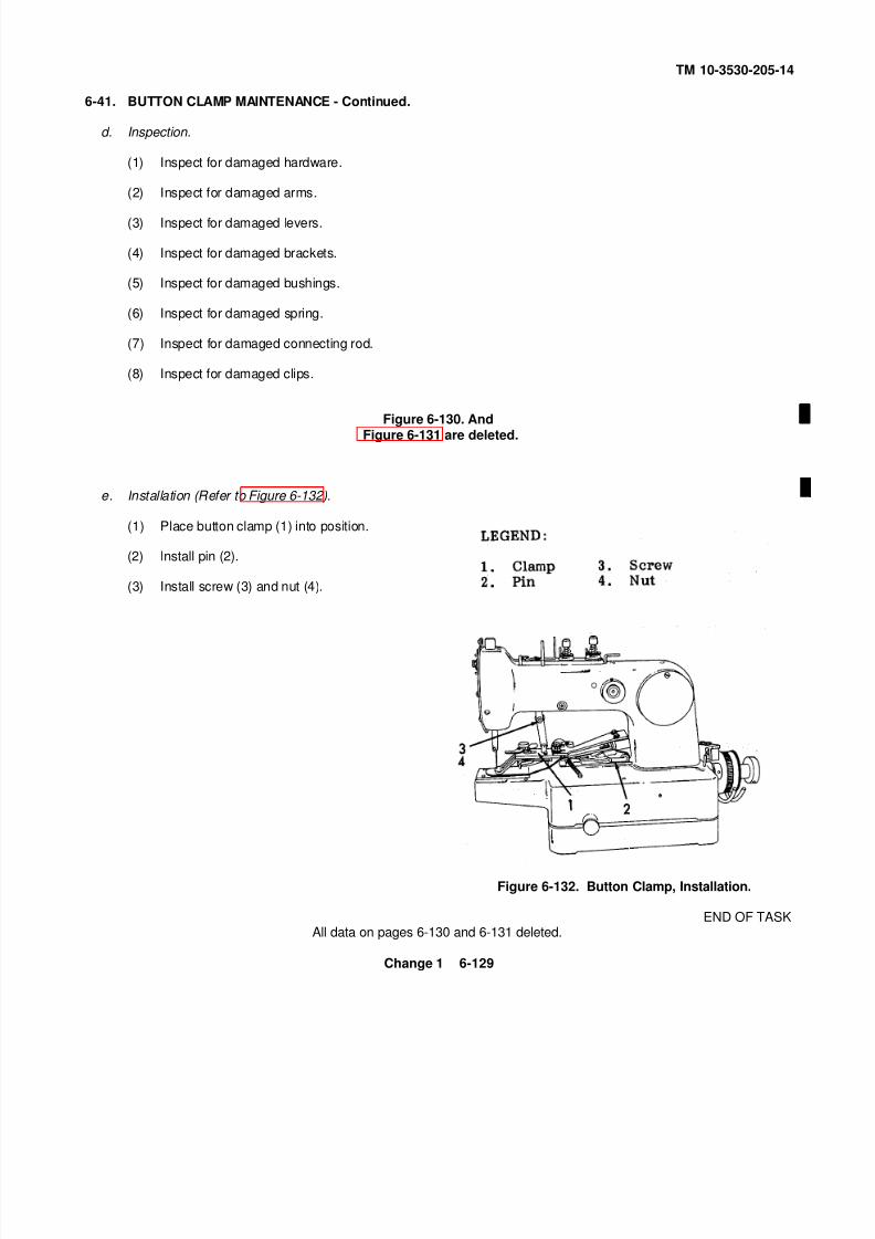
8/7/2019 TM 10-3530-205-10 CLOTHING REPAIR SHOP
http://slidepdf.com/reader/full/tm-10-3530-205-10-clothing-repair-shop 351/455
TM 10-3530-205-14
6-41. BUTTON CLAMP MAINTENANCE - Continued.
d. Inspection.
(1) Inspect for damaged hardware.
(2) Inspect for damaged arms.(3) Inspect for damaged levers.
(4) Inspect for damaged brackets.
(5) Inspect for damaged bushings.
(6) Inspect for damaged spring.
(7) Inspect for damaged connecting rod.
(8) Inspect for damaged clips.
Figure 6-130. AndFigure 6-131 are deleted.
e. Installation (Refer to Figure 6-132) .
(1) Place button clamp (1) into position.
(2) Install pin (2).
(3) Install screw (3) and nut (4).
Figure 6-132. Button Clamp, Installation.
END OF TASKAll data on pages 6-130 and 6-131 deleted.
Change 1 6-129

8/7/2019 TM 10-3530-205-10 CLOTHING REPAIR SHOP
http://slidepdf.com/reader/full/tm-10-3530-205-10-clothing-repair-shop 352/455
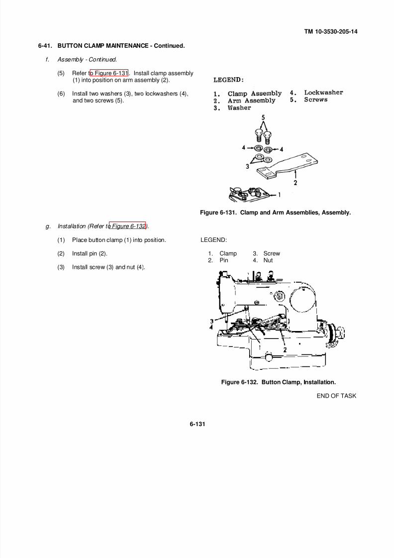
8/7/2019 TM 10-3530-205-10 CLOTHING REPAIR SHOP
http://slidepdf.com/reader/full/tm-10-3530-205-10-clothing-repair-shop 353/455
TM 10-3530-205-14
6-41. BUTTON CLAMP MAINTENANCE - Continued.
f. Assembly - Continued.
(5) Refer t o Figure 6-131 . Install clamp assembly(1) into position on arm assembly (2).
(6) Install two washers (3), two lockwashers (4),and two screws (5).
Figure 6-131. Clamp and Arm Assemblies, Assembly.
g. Installation (Refer to Figure 6-132) .
(1) Place button clamp (1) into position.
(2) Install pin (2).
(3) Install screw (3) and nut (4).
LEGEND:
1. Clamp 3. Screw2. Pin 4. Nut
Figure 6-132. Button Clamp, Installation.
END OF TASK
6-131
8/7/2019 TM 10-3530-205-10 CLOTHING REPAIR SHOP
http://slidepdf.com/reader/full/tm-10-3530-205-10-clothing-repair-shop 354/455
TM 10-3530-205-14
6-42. F OOT TREADLE LEVER ASSEMBLIES MAINTENANCE.
This task covers:a. Removal b. Cleaning c. Inspection d. Repaire. Installation
INITIAL SETUP EquipmentConditionApplicable Configuration Para. Condition Description
All 2-9 Electrical powerremoved.
Test Equipment 2-14 Thread and needleNone removed.
Special Tools Special Environmental ConditionsNone None
Materials/Parts Personnel RequiredCleaning Solvent 1 Person
(Appendix E , item 2)Cloth, Soft, Lint-Free(Appendix E , item 3)
Brush, Medium Bristle(Appendix E, item 1)
General Safety Instructions
WARNING
Cleaning solvent, Federal Specification P-D-680, is both toxic and flammable. Keep off skin. Use only in a well-ventilated area and avoid prolonged breathing of vapors. Keep away from open flame.
GO TO NEXT PAGE
6-132
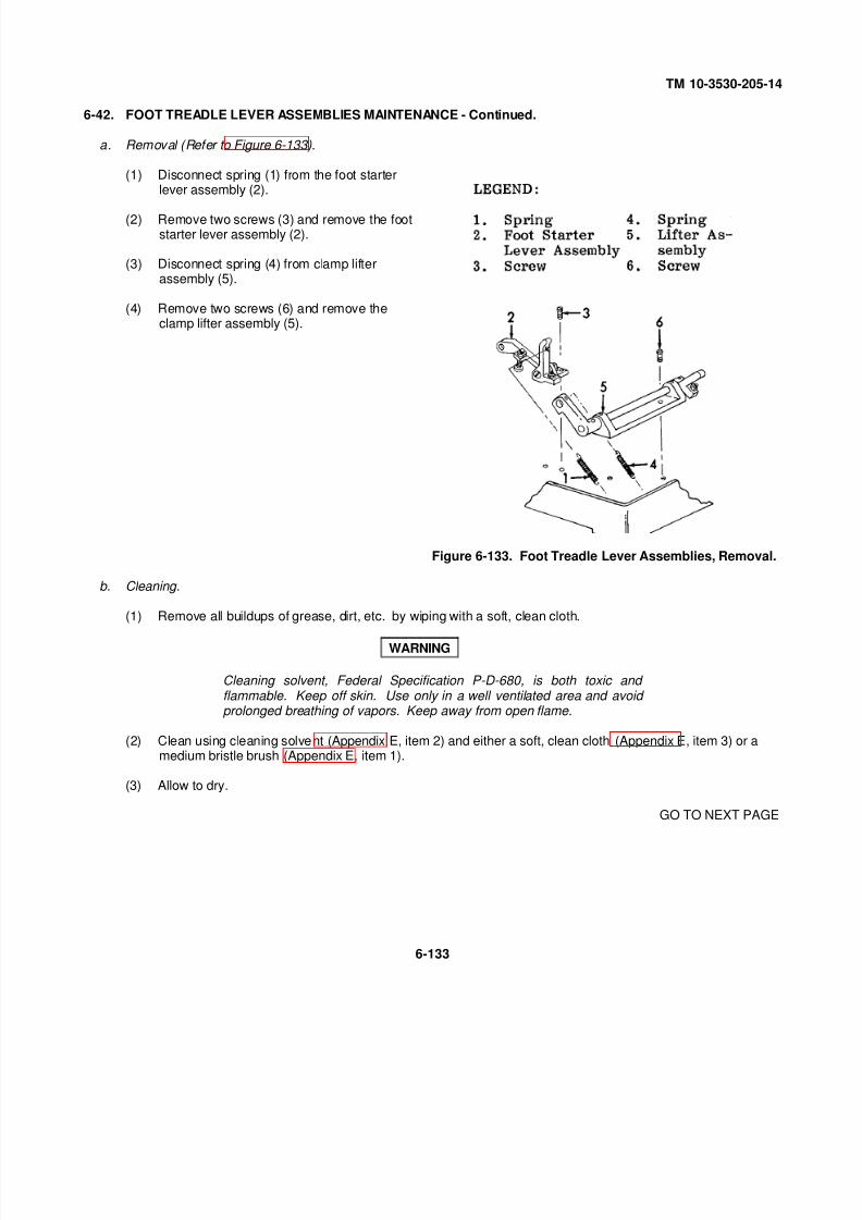
8/7/2019 TM 10-3530-205-10 CLOTHING REPAIR SHOP
http://slidepdf.com/reader/full/tm-10-3530-205-10-clothing-repair-shop 355/455
TM 10-3530-205-14
6-42. FOOT TREADLE LEVER ASSEMBLIES MAINTENANCE - Continued.
a. Removal (Refer t o Figure 6-133) .
(1) Disconnect spring (1) from the foot starter
lever assembly (2).(2) Remove two screws (3) and remove the foot
starter lever assembly (2).
(3) Disconnect spring (4) from clamp lifterassembly (5).
(4) Remove two screws (6) and remove theclamp lifter assembly (5).
Figure 6-133. Foot Treadle Lever Assemblies, Removal.
b. Cleaning.(1) Remove all buildups of grease, dirt, etc. by wiping with a soft, clean cloth.
WARNING
Cleaning solvent, Federal Specification P-D-680, is both toxic and flammable. Keep off skin. Use only in a well ventilated area and avoid prolonged breathing of vapors. Keep away from open flame.
(2) Clean using cleaning solve nt (Appendix E, item 2) and either a soft, clean cloth (Appendix E , item 3) or amedium bristle brush (Appendix E, item 1).
(3) Allow to dry.
GO TO NEXT PAGE
6-133
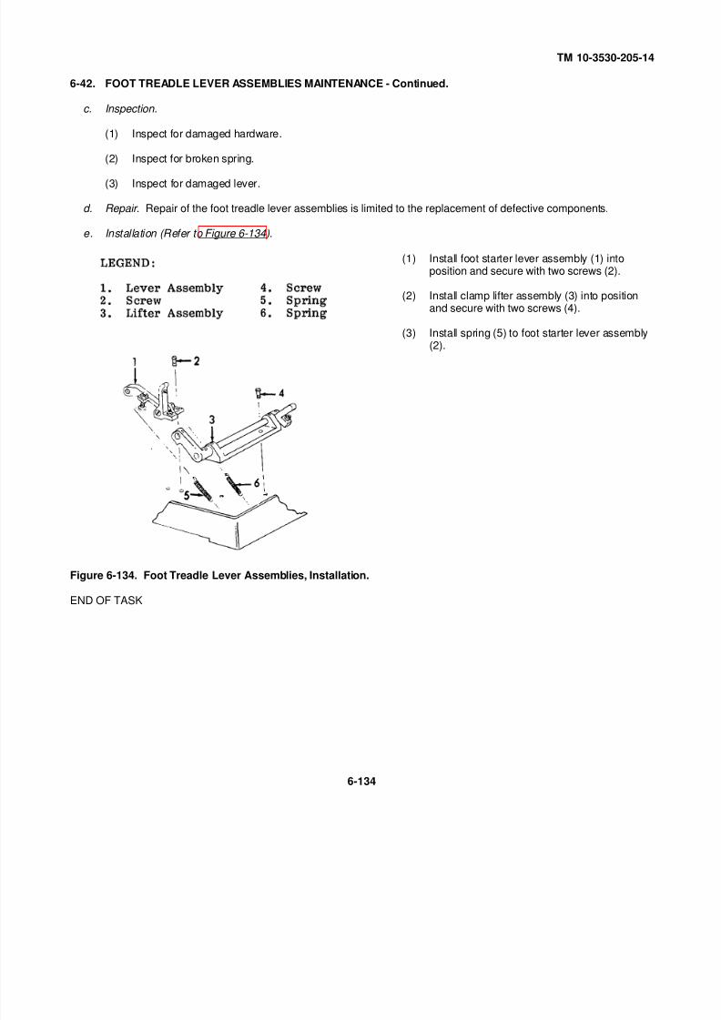
8/7/2019 TM 10-3530-205-10 CLOTHING REPAIR SHOP
http://slidepdf.com/reader/full/tm-10-3530-205-10-clothing-repair-shop 356/455
TM 10-3530-205-14
6-42. FOOT TREADLE LEVER ASSEMBLIES MAINTENANCE - Continued.
c. Inspection.
(1) Inspect for damaged hardware.
(2) Inspect for broken spring.(3) Inspect for damaged lever.
d. Repair . Repair of the foot treadle lever assemblies is limited to the replacement of defective components.
e. Installation (Refer to Figure 6-134) .
(1) Install foot starter lever assembly (1) intoposition and secure with two screws (2).
(2) Install clamp lifter assembly (3) into positionand secure with two screws (4).
(3) Install spring (5) to foot starter lever assembly(2).
Figure 6-134. Foot Treadle Lever Assemblies, Installation.
END OF TASK
6-134
8/7/2019 TM 10-3530-205-10 CLOTHING REPAIR SHOP
http://slidepdf.com/reader/full/tm-10-3530-205-10-clothing-repair-shop 357/455
TM 10-3530-205-14
6-43. N EEDLE BAR DRIVE MECHANISM MAINTENANCE.
This task covers:a. Removal b. Cleaning c. Inspection d. Repaire. Installation
INITIAL SETUP EquipmentConditionApplicable Configuration Para. Condition Description
All 2-9 Electrical powerremoved.
Test Equipment 2-14 Thread and needleNone removed.
6-40 Face Plate Removed
Special Tools Special Environmental ConditionsNone None
Materials/Parts Personnel Required
Cleaning Solvent 1 Person(Appendix E , item 2)Cloth, Soft, Lint-Free
(Appendix E , item 3)Brush, Medium Bristle
(Appendix E, item 1)
General Safety Instructions
WARNING
Cleaning solvent, Federal Specification P-D-680, is both toxic and flammable. Keep off skin. Use only in a well-ventilated area and avoid
prolonged breathing of vapors. Keep away from open flame.
GO TO NEXT PAGE
6-135
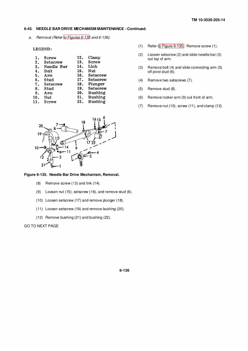
8/7/2019 TM 10-3530-205-10 CLOTHING REPAIR SHOP
http://slidepdf.com/reader/full/tm-10-3530-205-10-clothing-repair-shop 358/455
TM 10-3530-205-14
6-43. NEEDLE BAR DRIVE MECHANISM MAINTENANCE - Continued.
a. Removal (Refer t o Figures 6-135 and 6-136).
(1) Refer t o Figure 6-135. Remove screw (1).
(2) Loosen setscrew (2) and slide needle bar (3)out top of arm.
(3) Remove bolt (4) and slide connecting arm (5)off pivot stud (6).
(4) Remove two setscrews (7).
(5) Remove stud (8).
(6) Remove rocker arm (9) out front of arm.
(7) Remove nut (10), screw (11), and clamp (12).
Figure 6-135. Needle Bar Drive Mechanism, Removal.
(8) Remove screw (13) and link (14).
(9) Loosen nut (15), setscrew (16), and remove stud (6).
(10) Loosen setscrew (17) and remove plunger (18).
(11) Loosen setscrew (19) and remove bushing (20).
(12) Remove bushing (21) and bushing (22).
GO TO NEXT PAGE
6-136
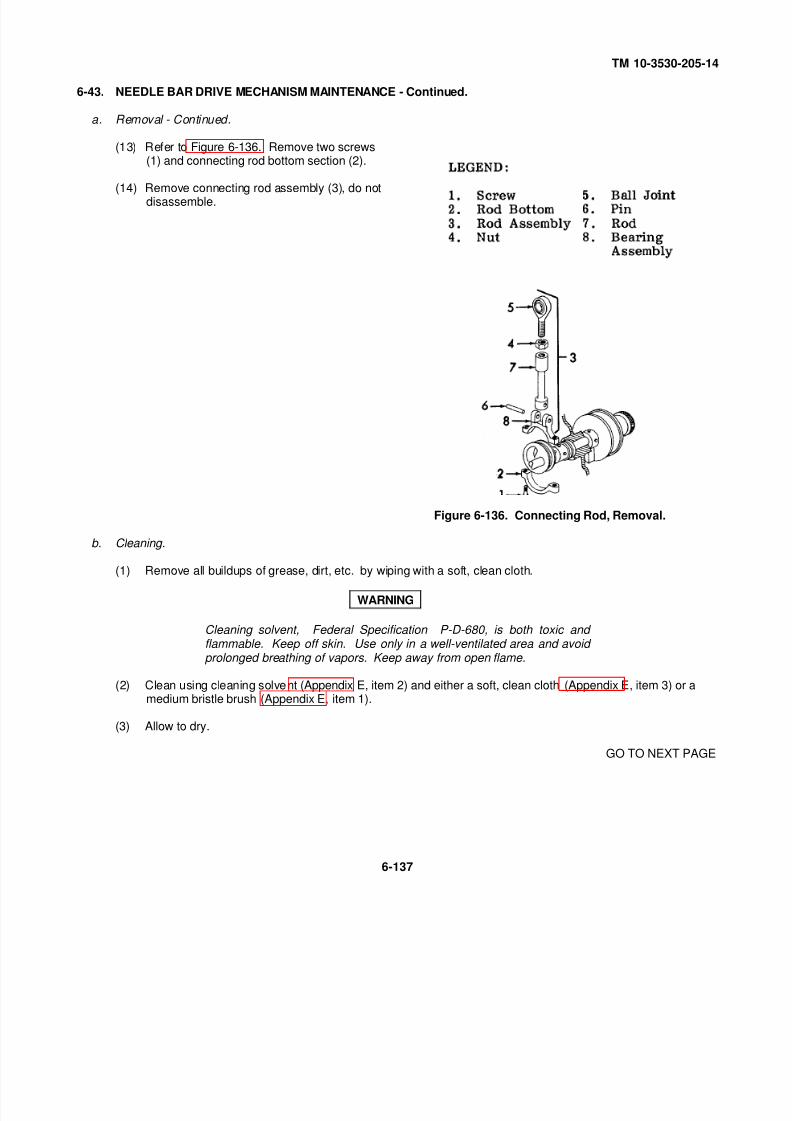
8/7/2019 TM 10-3530-205-10 CLOTHING REPAIR SHOP
http://slidepdf.com/reader/full/tm-10-3530-205-10-clothing-repair-shop 359/455
TM 10-3530-205-14
6-43. NEEDLE BAR DRIVE MECHANISM MAINTENANCE - Continued.
a. Removal - Continued.
(13) Refer to Figure 6-136. Remove two screws(1) and connecting rod bottom section (2).
(14) Remove connecting rod assembly (3), do notdisassemble.
Figure 6-136. Connecting Rod, Removal.
b. Cleaning.
(1) Remove all buildups of grease, dirt, etc. by wiping with a soft, clean cloth.
WARNING
Cleaning solvent, Federal Specification P-D-680, is both toxic and flammable. Keep off skin. Use only in a well-ventilated area and avoid prolonged breathing of vapors. Keep away from open flame.
(2) Clean using cleaning solve nt (Appendix E, item 2) and either a soft, clean cloth (Appendix E , item 3) or amedium bristle brush (Appendix E, item 1).
(3) Allow to dry.
GO TO NEXT PAGE
6-137
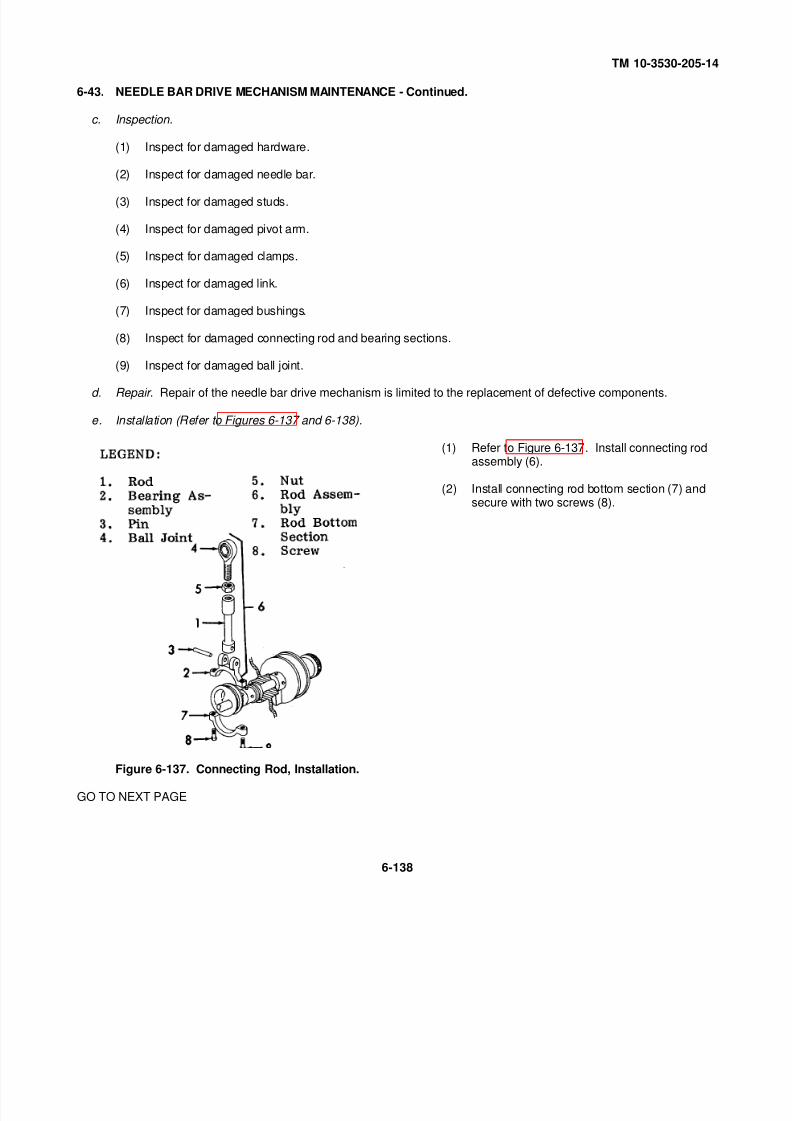
8/7/2019 TM 10-3530-205-10 CLOTHING REPAIR SHOP
http://slidepdf.com/reader/full/tm-10-3530-205-10-clothing-repair-shop 360/455
TM 10-3530-205-14
6-43. NEEDLE BAR DRIVE MECHANISM MAINTENANCE - Continued.
c. Inspection.
(1) Inspect for damaged hardware.
(2) Inspect for damaged needle bar.(3) Inspect for damaged studs.
(4) Inspect for damaged pivot arm.
(5) Inspect for damaged clamps.
(6) Inspect for damaged link.
(7) Inspect for damaged bushings.
(8) Inspect for damaged connecting rod and bearing sections.
(9) Inspect for damaged ball joint.
d. Repair . Repair of the needle bar drive mechanism is limited to the replacement of defective components.
e. Installation (Refer t o Figures 6-137 and 6-138).
(1) Refer t o Figure 6-137 . Install connecting rodassembly (6).
(2) Install connecting rod bottom section (7) andsecure with two screws (8).
Figure 6-137. Connecting Rod, Installation.
GO TO NEXT PAGE
6-138
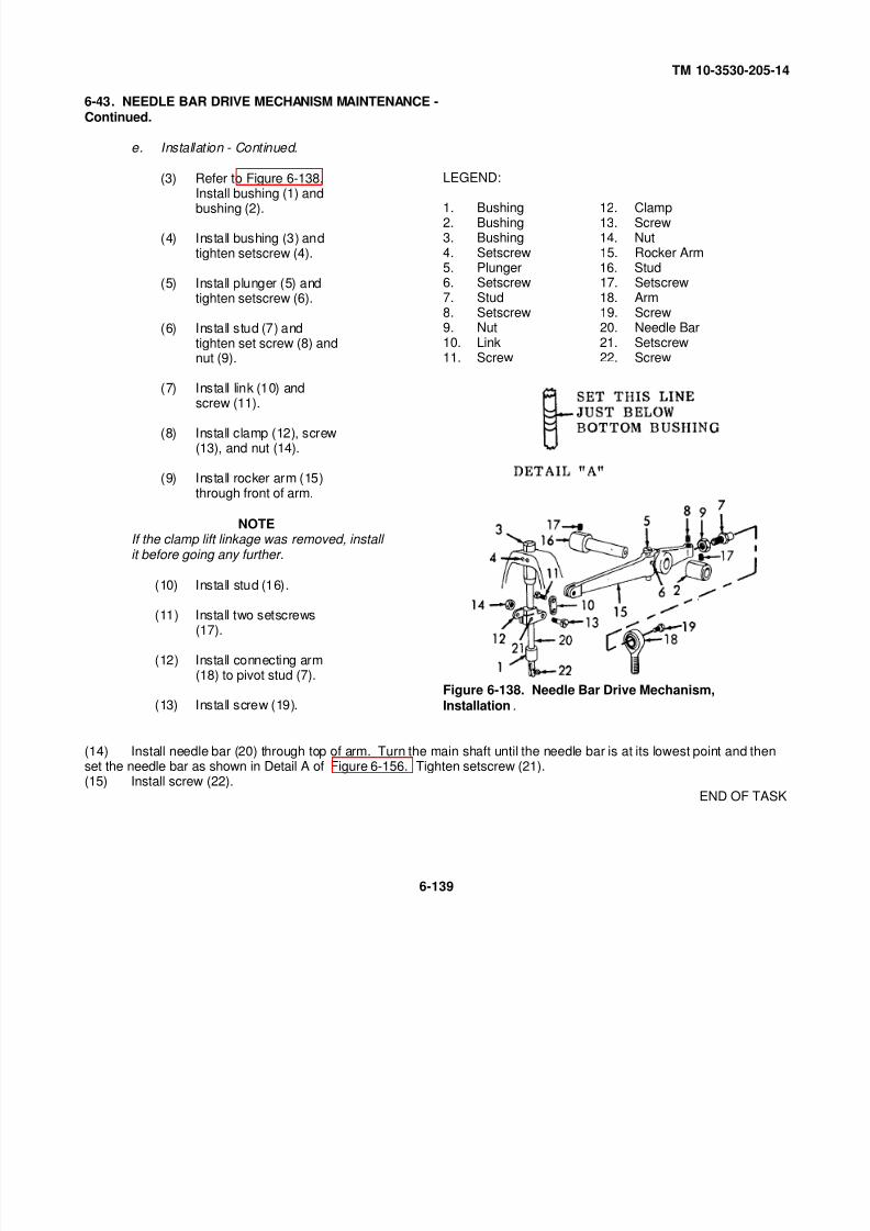
8/7/2019 TM 10-3530-205-10 CLOTHING REPAIR SHOP
http://slidepdf.com/reader/full/tm-10-3530-205-10-clothing-repair-shop 361/455
TM 10-3530-205-14
6-43. NEEDLE BAR DRIVE MECHANISM MAINTENANCE -Continued.
e. Installation - Continued.
(3) Refer t o Figure 6-138.
Install bushing (1) andbushing (2).
(4) Install bushing (3) andtighten setscrew (4).
(5) Install plunger (5) andtighten setscrew (6).
(6) Install stud (7) andtighten set screw (8) andnut (9).
(7) Install link (10) andscrew (11).
(8) Install clamp (12), screw(13), and nut (14).
(9) Install rocker arm (15)through front of arm.
NOTEIf the clamp lift linkage was removed, install it before going any further.
(10) Install stud (16).
(11) Install two setscrews(17).
(12) Install connecting arm(18) to pivot stud (7).
(13) Install screw (19).
LEGEND:
1. Bushing 12. Clamp2. Bushing 13. Screw3. Bushing 14. Nut4. Setscrew 15. Rocker Arm5. Plunger 16. Stud6. Setscrew 17. Setscrew7. Stud 18. Arm8. Setscrew 19. Screw9. Nut 20. Needle Bar10. Link 21. Setscrew11. Screw 22. Screw
Figure 6-138. Needle Bar Drive Mechanism,Installation .
(14) Install needle bar (20) through top of arm. Turn the main shaft until the needle bar is at its lowest point and thenset the needle bar as shown in Detail A of Figure 6-156. Tighten setscrew (21).(15) Install screw (22).
END OF TASK
6-139
8/7/2019 TM 10-3530-205-10 CLOTHING REPAIR SHOP
http://slidepdf.com/reader/full/tm-10-3530-205-10-clothing-repair-shop 362/455
TM 10-3530-205-14
6-44. C LAMP LIFT AND THREAD SLACK MECHANISMMAINTENANCE.
This task covers:a. Removal b. Cleaning c. Inspectiond. Repair e. Installation
INITIAL SETUP EquipmentCondition
Applicable Configurations Para. Condition DescriptionAll 2-9 Electrical power
removed.Test Equipment 2-14 Thread and needle
None removed.6-40 Face plate removed.
Special Tools 6-43 Needle bar driveNone mechanism removed.
Material/Parts Special Environmental ConditionsCleaning Solvent None
(Appendix E , item 2)Cloth, Soft, Lint-Free Personnel Required
(Appendix E , item 3) 1 PersonBrush, Medium Bristle
(Appendix E, item 1)
General Safety Instructions
WARNING
Cleaning solvent, Federal Specification P-D-680, is both toxic and flammable. Keep off skin. Use only in a well-ventilated area and avoid prolonged breathing of vapors. Keep away from open flame.
GO TO NEXT PAGE
6-140
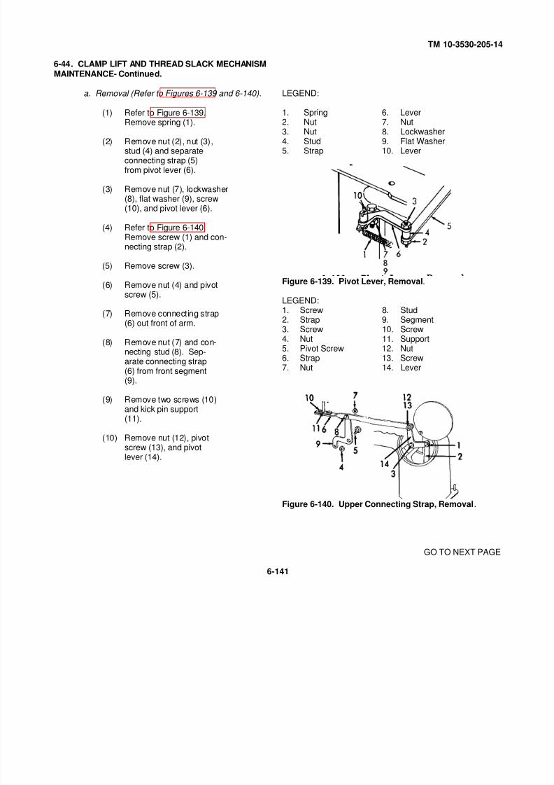
8/7/2019 TM 10-3530-205-10 CLOTHING REPAIR SHOP
http://slidepdf.com/reader/full/tm-10-3530-205-10-clothing-repair-shop 363/455
TM 10-3530-205-14
6-44. CLAMP LIFT AND THREAD SLACK MECHANISMMAINTENANCE- Continued.
a. Removal (Refer to Figures 6-139 and 6-140).
(1) Refer t o Figure 6-139.
Remove spring (1).(2) Remove nut (2), nut (3),
stud (4) and separateconnecting strap (5)from pivot lever (6).
(3) Remove nut (7), lockwasher(8), flat washer (9), screw(10), and pivot lever (6).
(4) Refer t o Figure 6-140.Remove screw (1) and con-necting strap (2).
(5) Remove screw (3).
(6) Remove nut (4) and pivotscrew (5).
(7) Remove connecting strap(6) out front of arm.
(8) Remove nut (7) and con-necting stud (8). Sep-arate connecting strap(6) from front segment(9).
(9) Remove two screws (10)and kick pin support(11).
(10) Remove nut (12), pivotscrew (13), and pivotlever (14).
LEGEND:
1. Spring 6. Lever
2. Nut 7. Nut3. Nut 8. Lockwasher4. Stud 9. Flat Washer5. Strap 10. Lever
Figure 6-139. Pivot Lever, Removal .
LEGEND:1. Screw 8. Stud2. Strap 9. Segment3. Screw 10. Screw4. Nut 11. Support5. Pivot Screw 12. Nut6. Strap 13. Screw7. Nut 14. Lever
Figure 6-140. Upper Connecting Strap, Removal .
GO TO NEXT PAGE
6-141
8/7/2019 TM 10-3530-205-10 CLOTHING REPAIR SHOP
http://slidepdf.com/reader/full/tm-10-3530-205-10-clothing-repair-shop 364/455
TM 10-3530-205-14
6-44. CLAMP LIFT AND THREAD SLACK MECHANISMMAINTENANCE - Continued.
b. Cleaning.(1) Remove all buildups of grease, dirt, etc. by wiping with a soft, clean cloth.
WARNING
Cleaning solvent, Federal Specification P-D-680, is both toxic and flammable. Keep off skin. Use only in a well-ventilated area and avoid prolonged breathing of vapors. Keep away from open flame.
(2) Clean using cleaning solve nt (Appendix E, item 2) and either a soft, clean cloth (Appendix E , item 3) ora medium bristle brush (Appendix E, item 1).
(3) Allow to dry.
c. Inspection.
(1) Inspect for damaged hardware.
(2) Inspect for broken spring.
(3) Inspect for damaged pivot levers.
(4) Inspect for damaged connecting straps.
(5) Inspect for damaged front segment.
(6) Inspect for damaged kick pin support.
d. Repair. Repair of the clamp lift and thread slack mechanism is limited to the replacement of defectivecomponents.
GO TO NEXT PAGE
6-142
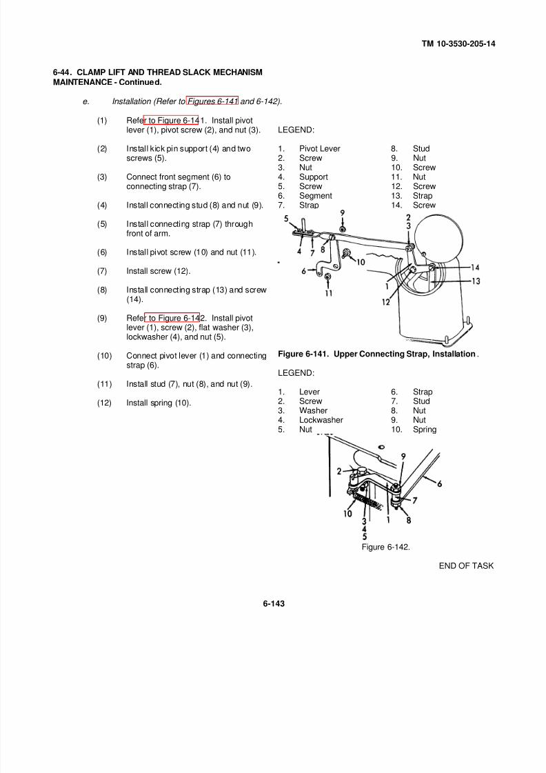
8/7/2019 TM 10-3530-205-10 CLOTHING REPAIR SHOP
http://slidepdf.com/reader/full/tm-10-3530-205-10-clothing-repair-shop 365/455
TM 10-3530-205-14
6-44. CLAMP LIFT AND THREAD SLACK MECHANISMMAINTENANCE - Continued.
e. Installation (Refer to Figures 6-141 and 6-142).
(1) Refe r to Figure 6-14 1. Install pivotlever (1), pivot screw (2), and nut (3).
(2) Install kick pin support (4) and twoscrews (5).
(3) Connect front segment (6) toconnecting strap (7).
(4) Install connecting stud (8) and nut (9).
(5) Install connecting strap (7) throughfront of arm.
(6) Install pivot screw (10) and nut (11).
(7) Install screw (12).
(8) Install connecting strap (13) and screw(14).
(9) Refer to Figure 6-14 2. Install pivotlever (1), screw (2), flat washer (3),lockwasher (4), and nut (5).
(10) Connect pivot lever (1) and connectingstrap (6).
(11) Install stud (7), nut (8), and nut (9).
(12) Install spring (10).
LEGEND:
1. Pivot Lever 8. Stud2. Screw 9. Nut3. Nut 10. Screw4. Support 11. Nut5. Screw 12. Screw6. Segment 13. Strap7. Strap 14. Screw
Figure 6-141. Upper Connecting Strap, Installation .
LEGEND:
1. Lever 6. Strap2. Screw 7. Stud3. Washer 8. Nut4. Lockwasher 9. Nut5. Nut 10. Spring
Figure 6-142.
END OF TASK
6-143
8/7/2019 TM 10-3530-205-10 CLOTHING REPAIR SHOP
http://slidepdf.com/reader/full/tm-10-3530-205-10-clothing-repair-shop 366/455
TM 10-3530-205-14
6-45. A UTOMATIC THREAD LOCKING MECHANISMMAINTENANCE.
This task covers:
a. Removal b. Cleaning c. Inspectiond. Repair e. Installation
INITIAL SETUP EquipmentCondition
Applicable Configurations Para. Condition DescriptionAll 2-9 Electrical power
removed.Test Equipment 2-14 Thread and needle
None removed.6-40 Face plate removed.
Special Tools 6-43 Needle bar driveNone mechanism removed.
Material/Parts Special Environmental ConditionsCleaning Solvent None
(Appendix E , item 2)Cloth, Soft, Lint-Free Personnel Required
(Appendix E , item 3) 1 PersonBrush, Medium Bristle
(Appendix E, item 1)
General Safety Instructions
WARNING
Cleaning solvent, Federal Specification P-D-680, is both toxic and flammable. Keep off skin. Use only in a well-ventilated area and avoid prolonged breathing of vapors. Keep away from open flame.
GO TO NEXT PAGE
6-144
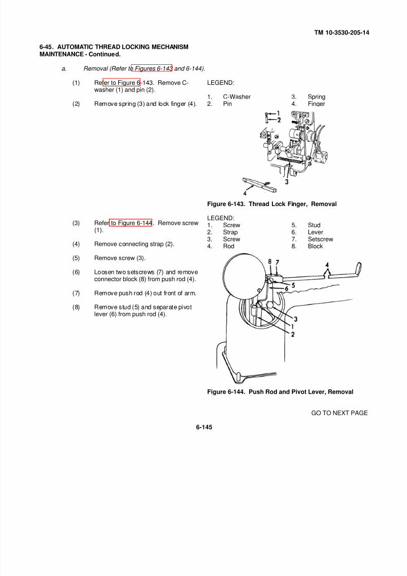
8/7/2019 TM 10-3530-205-10 CLOTHING REPAIR SHOP
http://slidepdf.com/reader/full/tm-10-3530-205-10-clothing-repair-shop 367/455
TM 10-3530-205-14
6-45. AUTOMATIC THREAD LOCKING MECHANISMMAINTENANCE - Continued.
a. Removal (Refer to Figures 6-143 and 6-144).
(1) Ref er to Figure 6 -143. Remove C-
washer (1) and pin (2).(2) Remove spring (3) and lock finger (4).
(3) Refer to Figure 6-144 . Remove screw(1).
(4) Remove connecting strap (2).
(5) Remove screw (3).
(6) Loosen two setscrews (7) and removeconnector block (8) from push rod (4).
(7) Remove push rod (4) out front of arm.
(8) Remove stud (5) and separate pivotlever (6) from push rod (4).
LEGEND:
1. C-Washer 3. Spring2. Pin 4. Finger
Figure 6-143. Thread Lock Finger, Removal
LEGEND:1. Screw 5. Stud2. Strap 6. Lever3. Screw 7. Setscrew4. Rod 8. Block
Figure 6-144. Push Rod and Pivot Lever, Removal
GO TO NEXT PAGE
6-145
8/7/2019 TM 10-3530-205-10 CLOTHING REPAIR SHOP
http://slidepdf.com/reader/full/tm-10-3530-205-10-clothing-repair-shop 368/455
TM 10-3530-205-14
6-45. AUTOMATIC THREAD LOCKING MECHANISMMAINTENANCE - Continued.
b. Cleaning.
(1) Remove all buildups of grease, dirt, etc. by wiping with a soft, clean cloth.WARNING
Cleaning solvent, Federal Specification P-D-680, is both toxic and flammable. Keep off skin. Use only in a well-ventilated area and avoid prolonged breathing of vapors. Keep away from open flame.
(2) Clean using cleaning solve nt (Appendix E, item 2) and either a soft, clean cloth (Appendix E , item 3)or a medium bristle brush (Appendix E, item 1).
(3) Allow to dry.
c. Inspection.(1) Inspect for damaged hardware.
(2) Inspect for damaged springs.
(3) Inspect for damaged lock finger.
(4) Inspect for damaged pin.
(5) Inspect for damaged connecting strap.
(6) Inspect for damaged push rod.
(7) Inspect for damaged connector block.
(8) Inspect for damaged pivot lever.
d. Repair. Repair of the automatic thread locking mechanism is limited to the replacement of defectivecomponents.
GO TO NEXT PAGE
6-146
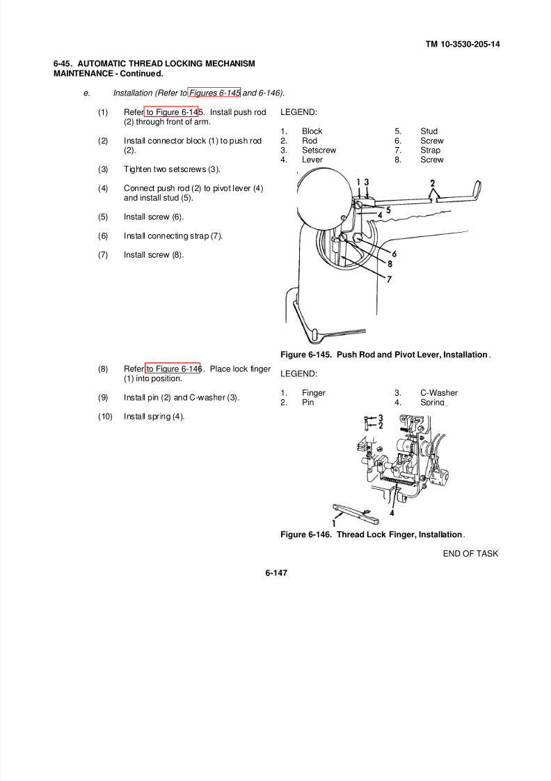
8/7/2019 TM 10-3530-205-10 CLOTHING REPAIR SHOP
http://slidepdf.com/reader/full/tm-10-3530-205-10-clothing-repair-shop 369/455
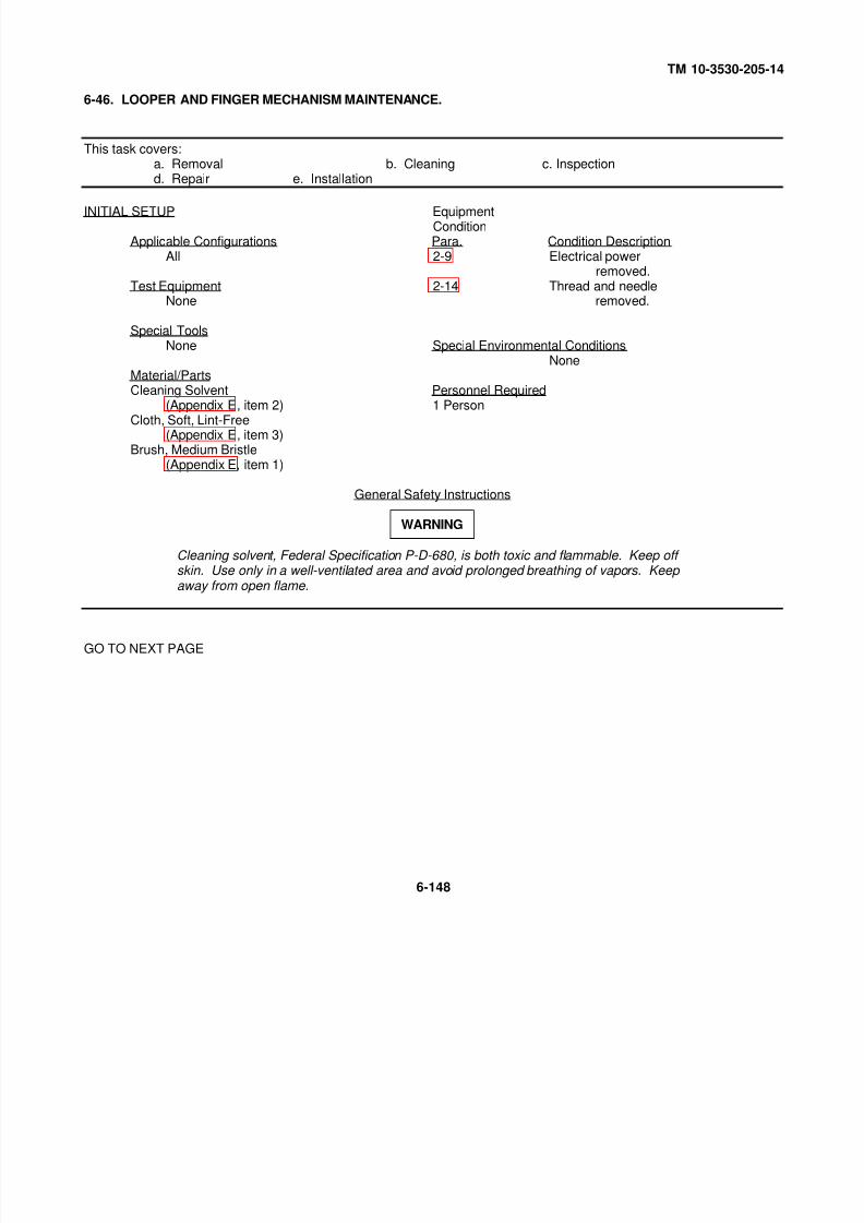
8/7/2019 TM 10-3530-205-10 CLOTHING REPAIR SHOP
http://slidepdf.com/reader/full/tm-10-3530-205-10-clothing-repair-shop 370/455
TM 10-3530-205-14
6-46. L OOPER AND FINGER MECHANISM MAINTENANCE.
This task covers:a. Removal b. Cleaning c. Inspectiond. Repair e. Installation
INITIAL SETUP EquipmentCondition
Applicable Configurations Para. Condition DescriptionAll 2-9 Electrical power
removed.Test Equipment 2-14 Thread and needle
None removed.
Special ToolsNone Special Environmental Conditions
NoneMaterial/Parts
Cleaning Solvent Personnel Required(Appendix E , item 2) 1 PersonCloth, Soft, Lint-Free
(Appendix E , item 3)Brush, Medium Bristle
(Appendix E, item 1)
General Safety Instructions
WARNING
Cleaning solvent, Federal Specification P-D-680, is both toxic and flammable. Keep off skin. Use only in a well-ventilated area and avoid prolonged breathing of vapors. Keep
away from open flame.
GO TO NEXT PAGE
6-148
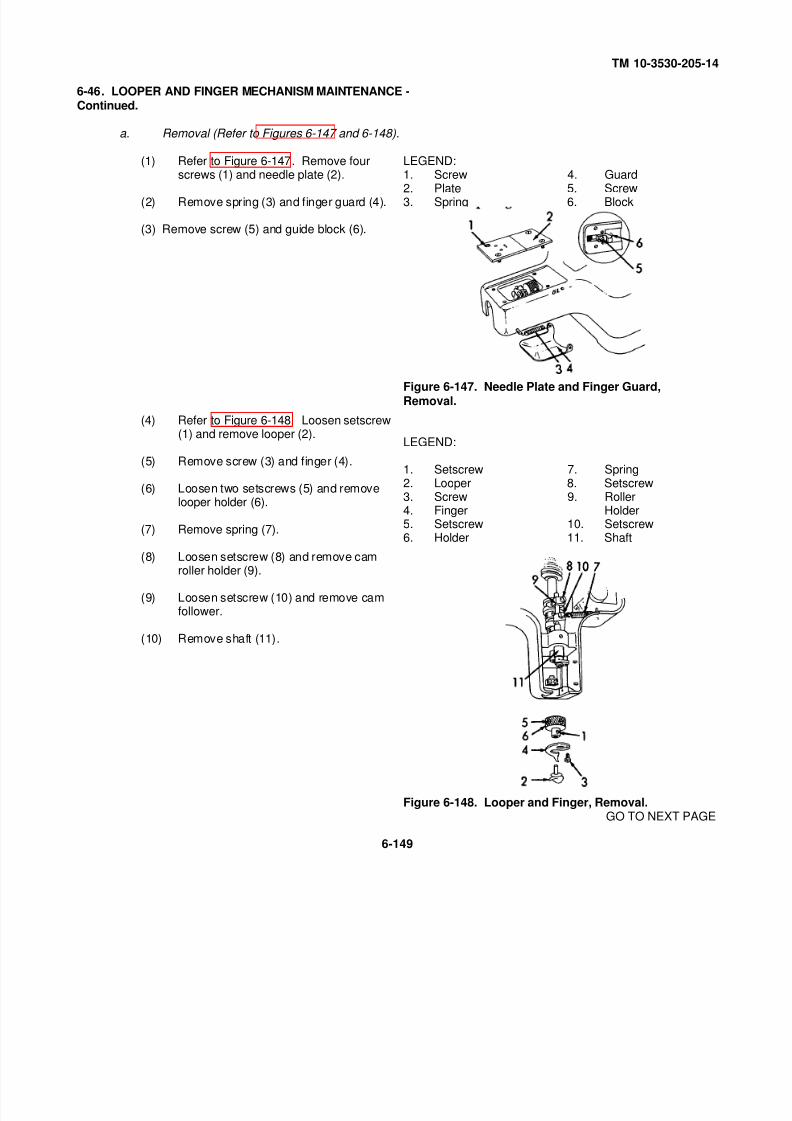
8/7/2019 TM 10-3530-205-10 CLOTHING REPAIR SHOP
http://slidepdf.com/reader/full/tm-10-3530-205-10-clothing-repair-shop 371/455
TM 10-3530-205-14
6-46. LOOPER AND FINGER MECHANISM MAINTENANCE -Continued.
a. Removal (Refer to Figures 6-147 and 6-148).
(1) Refer to Figure 6-147 . Remove four
screws (1) and needle plate (2).(2) Remove spring (3) and finger guard (4).
(3) Remove screw (5) and guide block (6).
(4) Refer to Figure 6-148. Loosen setscrew(1) and remove looper (2).
(5) Remove screw (3) and finger (4).
(6) Loosen two setscrews (5) and removelooper holder (6).
(7) Remove spring (7).
(8) Loosen setscrew (8) and remove camroller holder (9).
(9) Loosen setscrew (10) and remove camfollower.
(10) Remove shaft (11).
LEGEND:
1. Screw 4. Guard2. Plate 5. Screw3. Spring 6. Block
Figure 6-147. Needle Plate and Finger Guard,Removal.
LEGEND:
1. Setscrew 7. Spring2. Looper 8. Setscrew3. Screw 9. Roller4. Finger Holder5. Setscrew 10. Setscrew
6. Holder 11. Shaft
Figure 6-148. Looper and Finger, Removal.GO TO NEXT PAGE
6-149
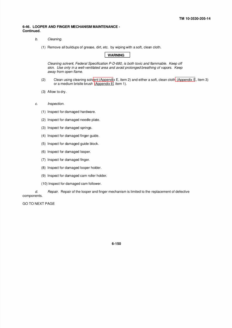
8/7/2019 TM 10-3530-205-10 CLOTHING REPAIR SHOP
http://slidepdf.com/reader/full/tm-10-3530-205-10-clothing-repair-shop 372/455
TM 10-3530-205-14
6-46. LOOPER AND FINGER MECHANISM MAINTENANCE -Continued.
b. Cleaning.
(1) Remove all buildups of grease, dirt, etc. by wiping with a soft, clean cloth.
WARNING
Cleaning solvent, Federal Specification P-D-680, is both toxic and flammable. Keep off skin. Use only in a well-ventilated area and avoid prolonged breathing of vapors. Keep away from open flame.
(2) Clean using cleaning solv ent (Appendi x E, item 2) and either a soft, clean cloth (Appendix E , item 3)or a medium bristle brush (Appendix E, item 1).
(3) Allow to dry.
c. Inspection.
(1) Inspect for damaged hardware.
(2) Inspect for damaged needle plate.
(3) Inspect for damaged springs.
(4) Inspect for damaged finger guide.
(5) Inspect for damaged guide block.
(6) Inspect for damaged looper.
(7) Inspect for damaged finger.
(8) Inspect for damaged looper holder.
(9) Inspect for damaged cam roller holder.
(10) Inspect for damaged cam follower.
d. Repair. Repair of the looper and finger mechanism is limited to the replacement of defectivecomponents.
GO TO NEXT PAGE
6-150
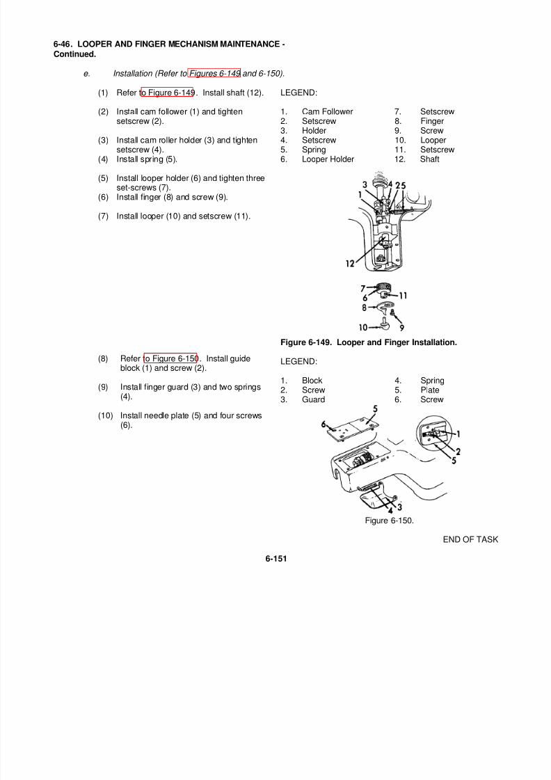
8/7/2019 TM 10-3530-205-10 CLOTHING REPAIR SHOP
http://slidepdf.com/reader/full/tm-10-3530-205-10-clothing-repair-shop 373/455
6-46. LOOPER AND FINGER MECHANISM MAINTENANCE -Continued.
e. Installation (Refer to Figures 6-149 and 6-150).
(1) Refer t o Figure 6-149 . Install shaft (12).
(2) Install cam follower (1) and tightensetscrew (2).
(3) Install cam roller holder (3) and tightensetscrew (4).
(4) Install spring (5).
(5) Install looper holder (6) and tighten threeset-screws (7).
(6) Install finger (8) and screw (9).
(7) Install looper (10) and setscrew (11).
(8) Refer t o Figure 6-150 . Install guideblock (1) and screw (2).
(9) Install finger guard (3) and two springs(4).
(10) Install needle plate (5) and four screws(6).
LEGEND:
1. Cam Follower 7. Setscrew2. Setscrew 8. Finger3. Holder 9. Screw4. Setscrew 10. Looper5. Spring 11. Setscrew6. Looper Holder 12. Shaft
Figure 6-149. Looper and Finger Installation.
LEGEND:
1. Block 4. Spring2. Screw 5. Plate3. Guard 6. Screw
Figure 6-150.
END OF TASK
6-151
8/7/2019 TM 10-3530-205-10 CLOTHING REPAIR SHOP
http://slidepdf.com/reader/full/tm-10-3530-205-10-clothing-repair-shop 374/455
TM 10-3530-205-14
6-47. S TITCH ADJUSTMENT MECHANISM MAINTENANCE.
This task covers:a. Removal b. Cleaning c. Inspectiond. Repair e. Installation
INITIAL SETUP EquipmentCondition
Applicable Configurations Para. Condition DescriptionAll 2-9 Electrical power
removed.Test Equipment 2-14 Thread and needle
None removed.
Special ToolsNone Special Environmental Conditions
NoneMaterial/PartsCleaning Solvent Personnel Required
(Appendix E , item 2) 1 PersonCloth, Soft, Lint-Free(Appendix E , item 3)
Brush, Medium Bristle(Appendix E, item 1)
General Safety Instructions
WARNING
Cleaning solvent, Federal Specification P-D-680, is both toxic and flammable. Keep off skin. Use only in a well-ventilated area and avoid prolonged breathing of vapors. Keep away from open flame.
GO TO NEXT PAGE
6-152
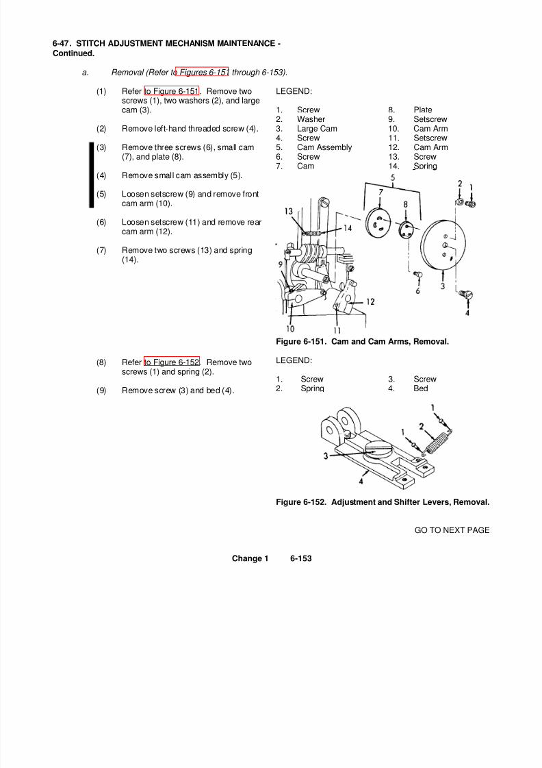
8/7/2019 TM 10-3530-205-10 CLOTHING REPAIR SHOP
http://slidepdf.com/reader/full/tm-10-3530-205-10-clothing-repair-shop 375/455
6-47. STITCH ADJUSTMENT MECHANISM MAINTENANCE -Continued.
a. Removal (Refer to Figures 6-151 through 6-153).
(1) Refer to Figure 6-151 . Remove twoscrews (1), two washers (2), and largecam (3).
(2) Remove left-hand threaded screw (4).
(3) Remove three screws (6), small cam(7), and plate (8).
(4) Remove small cam assembly (5).
(5) Loosen setscrew (9) and remove frontcam arm (10).
(6) Loosen setscrew (11) and remove rearcam arm (12).
(7) Remove two screws (13) and spring(14).
(8) Refer to Figure 6-152. Remove two
screws (1) and spring (2).
(9) Remove screw (3) and bed (4).
LEGEND:
1. Screw 8. Plate2. Washer 9. Setscrew3. Large Cam 10. Cam Arm4. Screw 11. Setscrew5. Cam Assembly 12. Cam Arm6. Screw 13. Screw7. Cam 14. Spring
Figure 6-151. Cam and Cam Arms, Removal.
LEGEND:
1. Screw 3. Screw2. Spring 4. Bed
Figure 6-152. Adjustment and Shifter Levers, Removal.
GO TO NEXT PAGE
Change 1 6-153
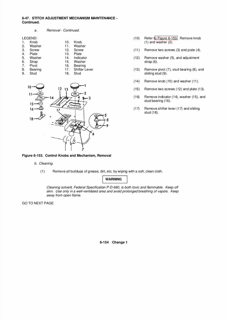
8/7/2019 TM 10-3530-205-10 CLOTHING REPAIR SHOP
http://slidepdf.com/reader/full/tm-10-3530-205-10-clothing-repair-shop 376/455
6-47. STITCH ADJUSTMENT MECHANISM MAINTENANCE -Continued.
a. Removal - Continued.
LEGEND:1. Knob 10. Knob2. Washer 11. Washer
3. Screw 12. Screw4. Plate 13. Plate5. Washer 14. Indicator6. Strap 15. Washer7. Pivot 16. Bearing8. Bearing 17. Shifter Lever9. Stud 18. Stud
Figure 6-153. Control Knobs and Mechanism, Removal
(10) Refer t o Figure 6-153. Remove knob(1) and washer (2).
(11) Remove two screws (3) and plate (4).(12) Remove washer (5), and adjustment
strap (6).
(13) Remove pivot (7), stud bearing (8), andsliding stud (9).
(14) Remove knob (10) and washer (11).
(15) Remove two screws (12) and plate (13).
(16) Remove indicator (14), washer (15), andstud bearing (16).
(17) Remove shifter lever (17) and slidingstud (18).
b. Cleaning.
(1) Remove all buildups of grease, dirt, etc. by wiping with a soft, clean cloth.
WARNING
Cleaning solvent, Federal Specification P-D-680, is both toxic and flammable. Keep off skin. Use only in a well-ventilated area and avoid prolonged breathing of vapors. Keep away from open flame.
GO TO NEXT PAGE
6-154 C hange 1
8/7/2019 TM 10-3530-205-10 CLOTHING REPAIR SHOP
http://slidepdf.com/reader/full/tm-10-3530-205-10-clothing-repair-shop 377/455
TM 10-3530-205-14
6-47. STITCH ADJUSTMENT MECHANISM MAINTENANCE -Continued.
b. Cleaning - Continued.
(2) Clean using cleaning solve nt (Appendix E, item 2) and either a soft, clean cloth (Appendix E , item 3) or
a medium bristle brush (Appendix E, item 1).(3) Allow to dry.
c. Inspection.
(1) Inspect for damaged hardware.
(2) Inspect for damaged spring.
(3) Inspect for damaged cams.
(4) Inspect for damaged gears.
(5) Inspect for damaged shaft.
(6) Inspect for damaged cam arms.
(7) Inspect for damaged plates.
(8) Inspect for damaged adjustment strap.
(9) Inspect for damaged shifter lever.
(10) Inspect for damaged knobs.
(11) Inspect for damaged pivot.
d. Repair. Repair of the stitch adjustment mechanism is limited to the replacement of defectivecomponents.
GO TO NEXT PAGE
6-155
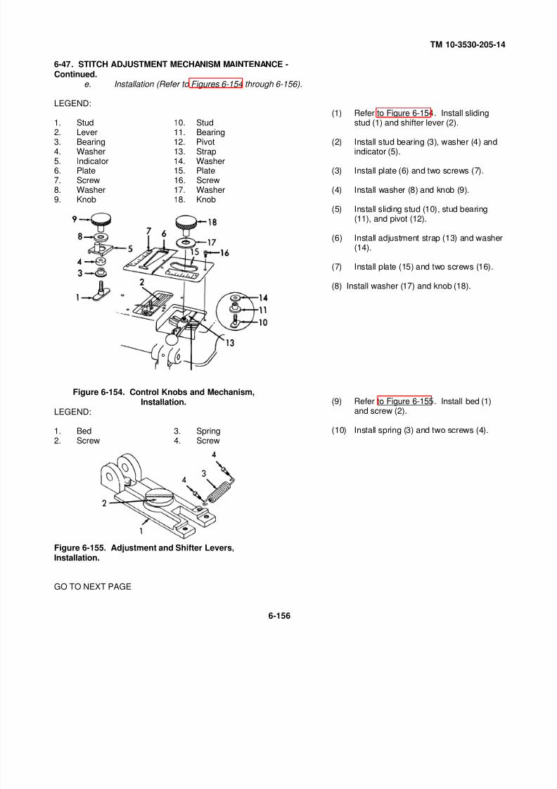
8/7/2019 TM 10-3530-205-10 CLOTHING REPAIR SHOP
http://slidepdf.com/reader/full/tm-10-3530-205-10-clothing-repair-shop 378/455
TM 10-3530-205-14
6-47. STITCH ADJUSTMENT MECHANISM MAINTENANCE -Continued.
e. Installation (Refer to Figures 6-154 through 6-156).
LEGEND:
1. Stud 10. Stud2. Lever 11. Bearing3. Bearing 12. Pivot4. Washer 13. Strap5. Indicator 14. Washer6. Plate 15. Plate7. Screw 16. Screw8. Washer 17. Washer9. Knob 18. Knob
Figure 6-154. Control Knobs and Mechanism,Installation.
LEGEND:
1. Bed 3. Spring2. Screw 4. Screw
Figure 6-155. Adjustment and Shifter Levers,Installation.
(1) Refer to Figure 6-154 . Install sliding
stud (1) and shifter lever (2).(2) Install stud bearing (3), washer (4) and
indicator (5).
(3) Install plate (6) and two screws (7).
(4) Install washer (8) and knob (9).
(5) Install sliding stud (10), stud bearing(11), and pivot (12).
(6) Install adjustment strap (13) and washer(14).
(7) Install plate (15) and two screws (16).
(8) Install washer (17) and knob (18).
(9) Refer to Figure 6-155 . Install bed (1)and screw (2).
(10) Install spring (3) and two screws (4).
GO TO NEXT PAGE
6-156
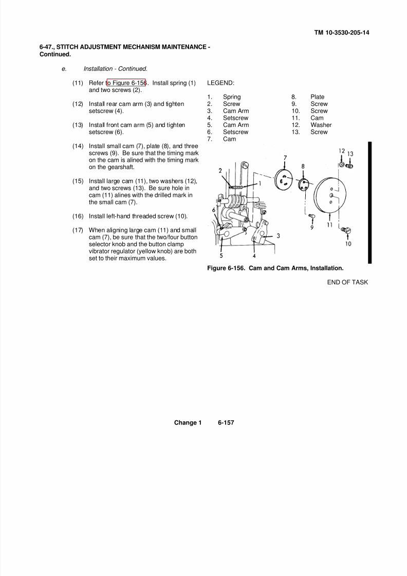
8/7/2019 TM 10-3530-205-10 CLOTHING REPAIR SHOP
http://slidepdf.com/reader/full/tm-10-3530-205-10-clothing-repair-shop 379/455
TM 10-3530-205-14
6-47., STITCH ADJUSTMENT MECHANISM MAINTENANCE -Continued.
e. Installation - Continued.
(11) Refer t o Figure 6-156 . Install spring (1)
and two screws (2).(12) Install rear cam arm (3) and tighten
setscrew (4).
(13) Install front cam arm (5) and tightensetscrew (6).
(14) Install small cam (7), plate (8), and threescrews (9). Be sure that the timing markon the cam is alined with the timing markon the gearshaft.
(15) Install large cam (11), two washers (12),and two screws (13). Be sure hole incam (11) alines with the drilled mark inthe small cam (7).
(16) Install left-hand threaded screw (10).
(17) When aligning large cam (11) and smallcam (7), be sure that the two/four buttonselector knob and the button clampvibrator regulator (yellow knob) are bothset to their maximum values.
LEGEND:
1. Spring 8. Plate2. Screw 9. Screw3. Cam Arm 10. Screw4. Setscrew 11. Cam5. Cam Arm 12. Washer6. Setscrew 13. Screw7. Cam
Figure 6-156. Cam and Cam Arms, Installation.
END OF TASK
Change 1 6-157
8/7/2019 TM 10-3530-205-10 CLOTHING REPAIR SHOP
http://slidepdf.com/reader/full/tm-10-3530-205-10-clothing-repair-shop 380/455
TM 10-3530-205-14
6-48. S TOPPING MECHANISM MAINTENANCE.
This task covers:a. Removal b. Cleaning c. Inspectiond. Repair e. Installation
INITIAL SETUP EquipmentCondition
Applicable Configurations Para. Condition DescriptionAll 2-9 Electrical power
removed.Test Equipment 2-14 Thread and needle
None removed.
Special ToolsNone Special Environmental Conditions
NoneMaterial/Parts
Cleaning Solvent Personnel Required(Appendix E , item 2) 1 PersonCloth, Soft, Lint-Free
(Appendix E , item 3)Brush, Medium Bristle
(Appendix E, item 1)
General Safety Instructions
WARNING
Cleaning solvent, Federal Specification P-D-680, is both toxic and flammable. Keep off skin. Use only in a well-ventilated area and avoid prolonged breathing of vapors. Keep away from open flame.
GO TO NEXT PAGE
6-158
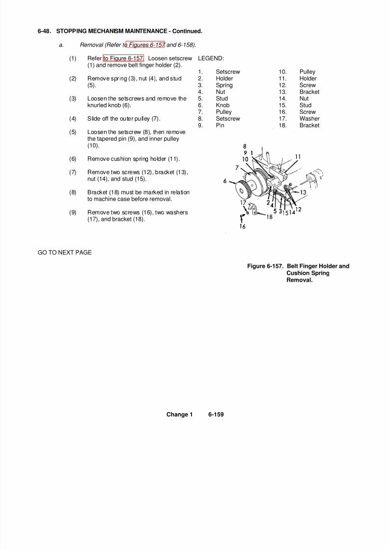
8/7/2019 TM 10-3530-205-10 CLOTHING REPAIR SHOP
http://slidepdf.com/reader/full/tm-10-3530-205-10-clothing-repair-shop 381/455
6-48. STOPPING MECHANISM MAINTENANCE - Continued.
a. Removal (Refer to Figures 6-157 and 6-158).
(1) Refer to Figure 6-157. Loosen setscrew(1) and remove belt finger holder (2).
(2) Remove spring (3), nut (4), and stud(5).
(3) Loosen the setscrews and remove theknurled knob (6).
(4) Slide off the outer pulley (7).
(5) Loosen the setscrew (8), then removethe tapered pin (9), and inner pulley(10).
(6) Remove cushion spring holder (11).
(7) Remove two screws (12), bracket (13),nut (14), and stud (15).
(8) Bracket (18) must be marked in relationto machine case before removal.
(9) Remove two screws (16), two washers(17), and bracket (18).
LEGEND:
1. Setscrew 10. Pulley2. Holder 11. Holder3. Spring 12. Screw4. Nut 13. Bracket5. Stud 14. Nut6. Knob 15. Stud7. Pulley 16. Screw8. Setscrew 17. Washer9. Pin 18. Bracket
GO TO NEXT PAGE
Figure 6-157. Belt Finger Holder andCushion SpringRemoval.
Change 1 6-159
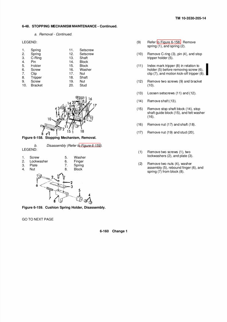
8/7/2019 TM 10-3530-205-10 CLOTHING REPAIR SHOP
http://slidepdf.com/reader/full/tm-10-3530-205-10-clothing-repair-shop 382/455
TM 10-3530-205-14
6-48. STOPPING MECHANISM MAINTENANCE - Continued.
a. Removal - Continued.
LEGEND:
1. Spring 11. Setscrew2. Spring 12. Setscrew3. C-Ring 13. Shaft4. Pin 14. Block5. Holder 15. Block6. Screw 16. Washer7. Clip 17. Nut8. Tripper 18. Shaft9. Screw 19. Nut10. Bracket 20. Stud
Figure 6-158. Stopping Mechanism, Removal.
b. Disassembly (Refer to Figure 6-159) .LEGEND:
1. Screw 5. Washer2. Lockwasher 6. Finger3. Plate 7. Spring4. Nut 8. Block
Figure 6-159. Cushion Spring Holder, Disassembly.
(9) Refer t o Figure 6-158. Removespring (1), and spring (2).
(10) Remove C-ring (3), pin (4), and stoptripper holder (5).
(11) Index mark tripper (8) in relation toholder (5) before removing screw (6),clip (7), and motion kick-off tripper (8).
(12) Remove two screws (9) and bracket(10).
(13) Loosen setscrews (11) and (12).
(14) Remove shaft (13).
(15) Remove stop shaft block (14), stopshaft guide block (15), and felt washer(16).
(16) Remove nut (17) and shaft (18).
(17) Remove nut (19) and stud (20).
(1) Remove two screws (1), two
lockwashers (2), and plate (3).
(2) Remove two nuts (4), washerassembly (5), rebound finger (6), andspring (7) from block (8).
GO TO NEXT PAGE
6-160 C hange 1
8/7/2019 TM 10-3530-205-10 CLOTHING REPAIR SHOP
http://slidepdf.com/reader/full/tm-10-3530-205-10-clothing-repair-shop 383/455
TM 10-3530-205-14
6-48. STOPPING MECHANISM MAINTENANCE - Continued.
c. Cleaning.
(1) Remove all buildups of grease, dirt, etc. by wiping with a soft, clean cloth.
WARNINGCleaning solvent, Federal Specification P-D-680, is both toxic and flammable. Keep off skin. Use only in a well-ventilated area and avoid prolonged breathing of vapors. Keep away from open flame.
(2) Clean using cleaning solv ent (Appendi x E, item 2) and either a soft, clean cloth (Appendix E , item 3)or a medium bristle brush (Appendix E, item 1).
(3) Allow to dry.
d. Inspection.
(1) Inspect for damaged hardware.(2) Inspect for damaged springs.
(3) Inspect for damaged belt finger holder.
(4) Inspect for damaged cushion spring holder.
(5) Inspect for damaged brackets.
(6) Inspect for damaged stop tripper holder.
(7) Inspect for damaged motion kick-off tripper.
(8) Inspect for damaged shaft.
(9) Inspect for damaged stop shaft block.
(10) Inspect for damaged stop shaft guide block.
(11) Inspect for damaged felt washer.
(12) Inspect for damaged rebound finger.
e. Repair. Repair of the stopping mechanism is limited to the replacement of defective components.
GO TO NEXT PAGE
6-161
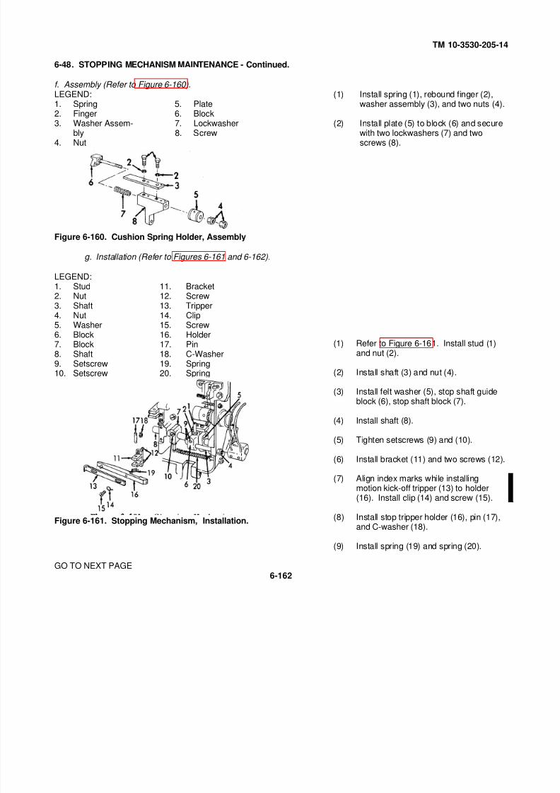
8/7/2019 TM 10-3530-205-10 CLOTHING REPAIR SHOP
http://slidepdf.com/reader/full/tm-10-3530-205-10-clothing-repair-shop 384/455
TM 10-3530-205-14
6-48. STOPPING MECHANISM MAINTENANCE - Continued.
f. Assembly (Refer to Figure 6-160) .LEGEND:1. Spring 5. Plate2. Finger 6. Block
3. Washer Assem- 7. Lockwasherbly 8. Screw4. Nut
Figure 6-160. Cushion Spring Holder, Assembly
g. Installation (Refer to Figures 6-161 and 6-162).
LEGEND:1. Stud 11. Bracket2. Nut 12. Screw3. Shaft 13. Tripper4. Nut 14. Clip5. Washer 15. Screw6. Block 16. Holder7. Block 17. Pin8. Shaft 18. C-Washer9. Setscrew 19. Spring10. Setscrew 20. Spring
Figure 6-161. Stopping Mechanism, Installation.
(1) Install spring (1), rebound finger (2),washer assembly (3), and two nuts (4).
(2) Install plate (5) to block (6) and securewith two lockwashers (7) and twoscrews (8).
(1) Refer to Figure 6-16 1. Install stud (1)and nut (2).
(2) Install shaft (3) and nut (4).
(3) Install felt washer (5), stop shaft guideblock (6), stop shaft block (7).
(4) Install shaft (8).
(5) Tighten setscrews (9) and (10).
(6) Install bracket (11) and two screws (12).
(7) Align index marks while installingmotion kick-off tripper (13) to holder(16). Install clip (14) and screw (15).
(8) Install stop tripper holder (16), pin (17),and C-washer (18).
(9) Install spring (19) and spring (20).
GO TO NEXT PAGE6-162
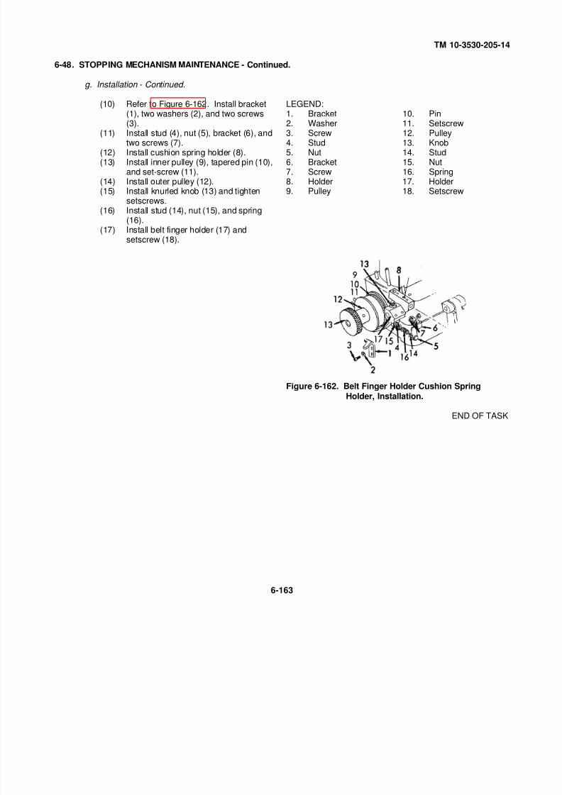
8/7/2019 TM 10-3530-205-10 CLOTHING REPAIR SHOP
http://slidepdf.com/reader/full/tm-10-3530-205-10-clothing-repair-shop 385/455
TM 10-3530-205-14
6-48. STOPPING MECHANISM MAINTENANCE - Continued.
g. Installation - Continued.
(10) Refer t o Figure 6-162 . Install bracket(1), two washers (2), and two screws(3).
(11) Install stud (4), nut (5), bracket (6), andtwo screws (7).
(12) Install cushion spring holder (8).(13) Install inner pulley (9), tapered pin (10),
and set-screw (11).(14) Install outer pulley (12).(15) Install knurled knob (13) and tighten
setscrews.(16) Install stud (14), nut (15), and spring
(16).(17) Install belt finger holder (17) and
setscrew (18).
LEGEND:1. Bracket 10. Pin2. Washer 11. Setscrew3. Screw 12. Pulley4. Stud 13. Knob5. Nut 14. Stud6. Bracket 15. Nut7. Screw 16. Spring8. Holder 17. Holder9. Pulley 18. Setscrew
Figure 6-162. Belt Finger Holder Cushion SpringHolder, Installation.
END OF TASK
6-163
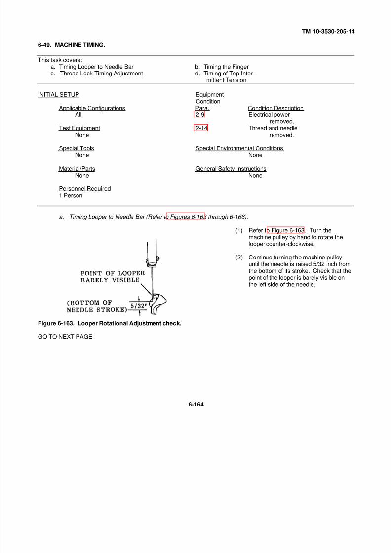
8/7/2019 TM 10-3530-205-10 CLOTHING REPAIR SHOP
http://slidepdf.com/reader/full/tm-10-3530-205-10-clothing-repair-shop 386/455
TM 10-3530-205-14
6-49. M ACHINE TIMING.
This task covers:a. Timing Looper to Needle Bar b. Timing the Fingerc. Thread Lock Timing Adjustment d. Timing of Top Inter-
mittent Tension
INITIAL SETUP EquipmentCondition
Applicable Configurations Para. Condition DescriptionAll 2-9 Electrical power
removed.Test Equipment 2-14 Thread and needle
None removed.
Special Tools Special Environmental ConditionsNone None
Material/Parts General Safety Instructions
None NonePersonnel Required1 Person
a. Timing Looper to Needle Bar (Refer t o Figures 6-163 through 6-166).
(1) Refer t o Figure 6-163 . Turn themachine pulley by hand to rotate thelooper counter-clockwise.
(2) Continue turning the machine pulleyuntil the needle is raised 5/32 inch fromthe bottom of its stroke. Check that thepoint of the looper is barely visible onthe left side of the needle.
Figure 6-163. Looper Rotational Adjustment check.
GO TO NEXT PAGE
6-164
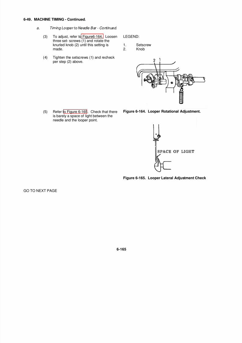
8/7/2019 TM 10-3530-205-10 CLOTHING REPAIR SHOP
http://slidepdf.com/reader/full/tm-10-3530-205-10-clothing-repair-shop 387/455
6-49. MACHINE TIMING - Continued.
a. Timing Looper to Needle Bar - Continued.
(3) To adjust, refer to Figure6-164. Loosenthree set- screws (1) and rotate theknurled knob (2) until this setting ismade.
(4) Tighten the setscrews (1) and recheckper step (2) above.
(5) Refer t o Figure 6-165 . Check that thereis barely a space of light between theneedle and the looper point.
LEGEND:
1. Setscrew2. Knob
Figure 6-164. Looper Rotational Adjustment.
Figure 6-165. Looper Lateral Adjustment Check
GO TO NEXT PAGE
6-165
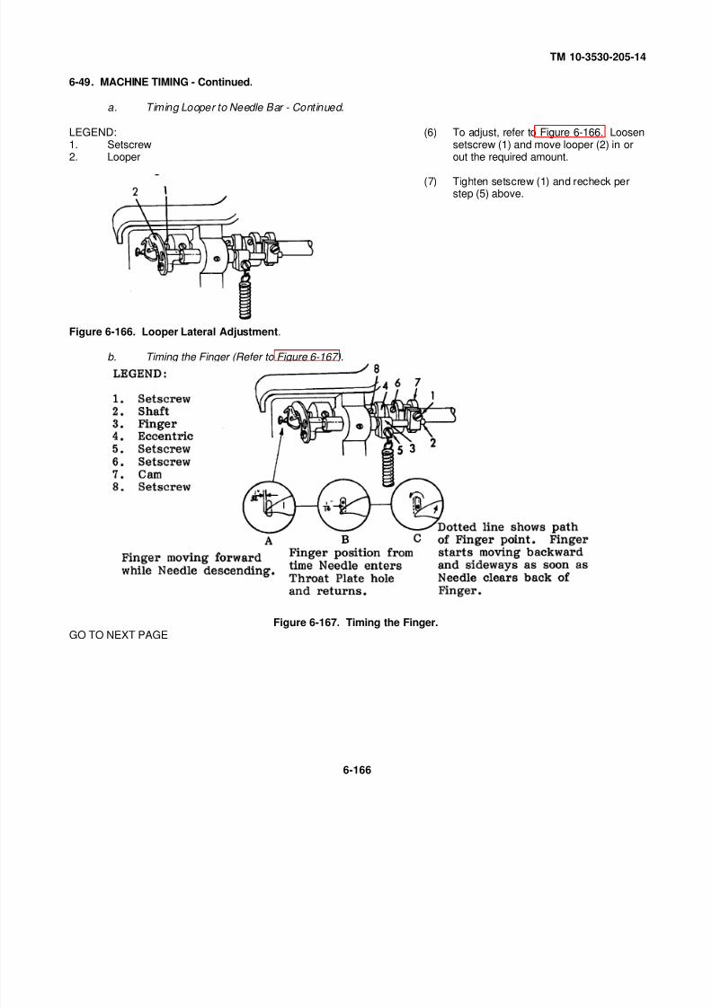
8/7/2019 TM 10-3530-205-10 CLOTHING REPAIR SHOP
http://slidepdf.com/reader/full/tm-10-3530-205-10-clothing-repair-shop 388/455
TM 10-3530-205-14
6-49. MACHINE TIMING - Continued.
a. Timing Looper to Needle Bar - Continued.
LEGEND:1. Setscrew
2. Looper
Figure 6-166. Looper Lateral Adjustment .
b. Timing the Finger (Refer to Figure 6-167) .
(6) To adjust, refer to Figure 6-166. Loosensetscrew (1) and move looper (2) in or
out the required amount.(7) Tighten setscrew (1) and recheck per
step (5) above.
Figure 6-167. Timing the Finger.GO TO NEXT PAGE
6-166
8/7/2019 TM 10-3530-205-10 CLOTHING REPAIR SHOP
http://slidepdf.com/reader/full/tm-10-3530-205-10-clothing-repair-shop 389/455
TM 10-3530-205-14
6-49. MACHINE TIMING - Continued.
b. Timing the Finger - Continued.
(1) Time the lateral setting first as follows:
(a) Rotate the machine pulley until the needle has descended fully and the looper finger hasreached the most forward position as shown by A. The point of the finger should be extended1/32 inch beyond the front edge of the slot in the throat plate.
(b) To adjust, loosen the setscrew (1) and move the shaft (2) in or out the required amount.
(c) Tighten the setscrew (1) and recheck per step (a) above.
(d) Be sure that the eccentric finger (3) does not bind against the shoulder of the eccentric (4). Ifbinding occurs, loosen the setscrew (5) and move the eccentric finger (3). Retighten setscrew(5).
(2) Time the radial setting as follows:
(a) Lower the needle (using the machine pulley) to the bottom of its stroke.
(b) Check for a 1/16 inch clearance between the needle and the back edge of the finger as shown byB.
(c) To adjust, loosen setscrew (5) and move the finger into the correct position.
(d) Retighten the setscrew and recheck per step (b) above.
(e) Turn the machine pulley counterclockwise and observe the finger movement. At the instant theneedle point has cleared the finger, the finger should start moving counterclockwise (backwardsand sideways at the same time) as shown by C.
(f) To adjust the sideways movement, loosen three setscrews (6) and rotate the barrel cam (7) toprovide the correct setting. Retighten the setscrews (6) and recheck finger movement.
(g) To adjust the backwards movement, loosen three setscrews (8) and rotate the finger eccentric(4) to provide the correct setting. Retighten the setscrews (8) and recheck finger movement.
GO TO NEXT PAGE
6-167
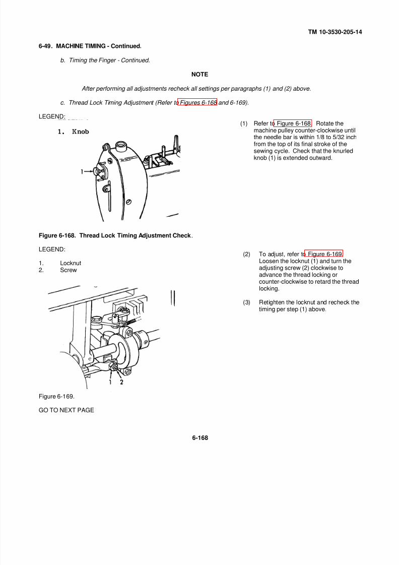
8/7/2019 TM 10-3530-205-10 CLOTHING REPAIR SHOP
http://slidepdf.com/reader/full/tm-10-3530-205-10-clothing-repair-shop 390/455
TM 10-3530-205-14
6-49. MACHINE TIMING - Continued.
b. Timing the Finger - Continued.
NOTE
After performing all adjustments recheck all settings per paragraphs (1) and (2) above.c. Thread Lock Timing Adjustment (Refer to Figures 6-168 and 6-169).
LEGEND:
Figure 6-168. Thread Lock Timing Adjustment Check .
LEGEND:
1. Locknut2. Screw
Figure 6-1 69.
(1) Refer to Figure 6-168. Rotate themachine pulley counter-clockwise untilthe needle bar is within 1/8 to 5/32 inchfrom the top of its final stroke of thesewing cycle. Check that the knurledknob (1) is extended outward.
(2) To adjust, refer to Figure 6-169.Loosen the locknut (1) and turn theadjusting screw (2) clockwise toadvance the thread locking orcounter-clockwise to retard the threadlocking.
(3) Retighten the locknut and recheck thetiming per step (1) above.
GO TO NEXT PAGE
6-168
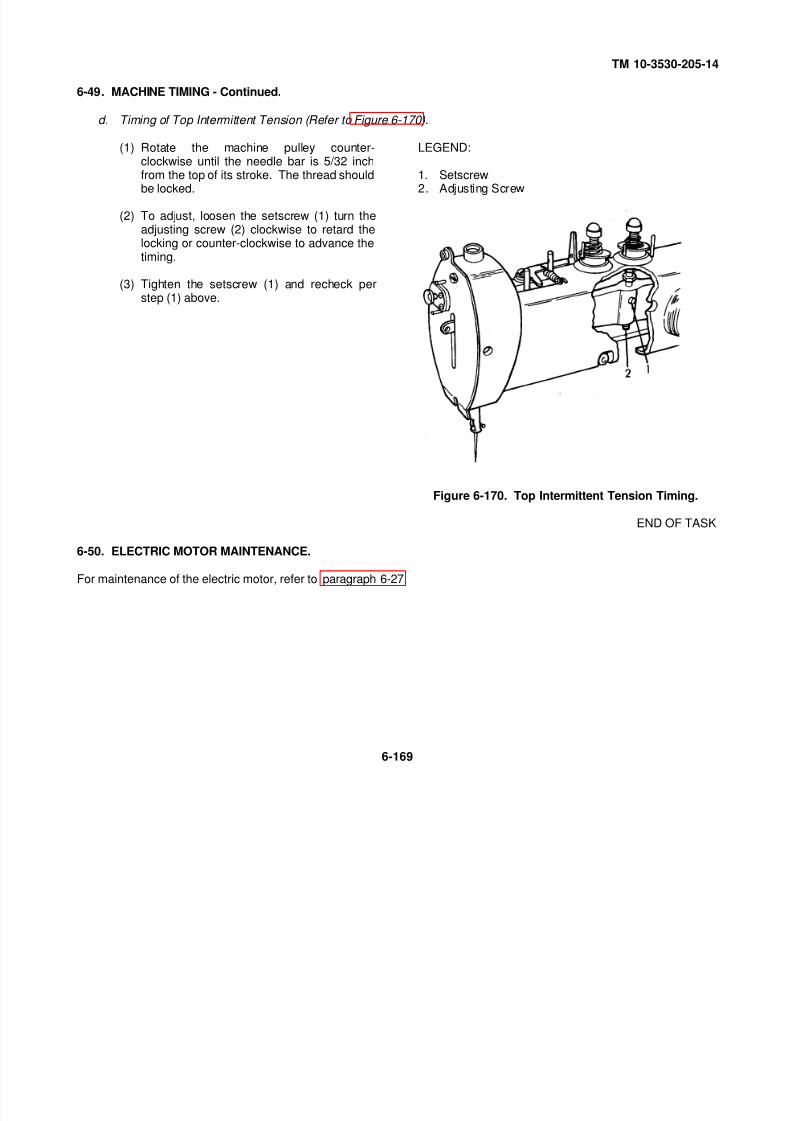
8/7/2019 TM 10-3530-205-10 CLOTHING REPAIR SHOP
http://slidepdf.com/reader/full/tm-10-3530-205-10-clothing-repair-shop 391/455
TM 10-3530-205-14
6-49. MACHINE TIMING - Continued.
d. Timing of Top Intermittent Tension (Refer to Figure 6-170) .
(1) Rotate the machine pulley counter-clockwise until the needle bar is 5/32 inch
from the top of its stroke. The thread shouldbe locked.
(2) To adjust, loosen the setscrew (1) turn theadjusting screw (2) clockwise to retard thelocking or counter-clockwise to advance thetiming.
(3) Tighten the setscrew (1) and recheck perstep (1) above.
LEGEND:
1. Setscrew2. Adjusting Screw
Figure 6-170. Top Intermittent Tension Timing.
END OF TASK
6-50. E LECTRIC MOTOR MAINTENANCE.
For maintenance of the electric motor, refer to paragraph 6-27.
6-169
8/7/2019 TM 10-3530-205-10 CLOTHING REPAIR SHOP
http://slidepdf.com/reader/full/tm-10-3530-205-10-clothing-repair-shop 392/455
TM 10-3530-205-14
6-51. S TORAGE BOX ASSEMBLY MAINTENANCE.
This task covers:a. Installed Item Inspection b. Removal c. Cleaningd. Inspection e. Repair f. Installation
INITIAL SETUP Equipment
ConditionApplicable Configurations Para. Condition DescriptionAll 2-9 Storage box removed.
Test Equipment Special Environmental ConditionsNone None
Special Tools General Safety InstructionsNone None
Material/Parts Personnel RequiredRivets 1 Person
a. Installed Item Inspection.
(1) Inspect for loose or missing handle.
(2) Inspect for rust, corrosion, and visible damage.
(3) Inspect for loose or damaged hinge.
(4) Inspect for loose or missing hardware.
b. Removal. Refer to paragraph 2-9.
c. Cleaning.(1) Clean the storage box assembly with a solution of mild soap and water.
(2) Rinse thoroughly with clean water.
(3) Allow to dry.
d. Inspection.
(1) Inspect for loose, missing, or damaged handle.
(2) Inspect for rust, corrosion, and visible damage.
(3) Inspect for loose or damaged hinge.
(4) Inspect for loose, missing, or damaged hardware.
GO TO NEXT PAGE
6-170
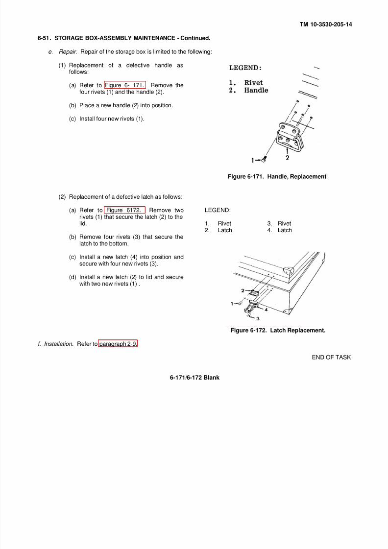
8/7/2019 TM 10-3530-205-10 CLOTHING REPAIR SHOP
http://slidepdf.com/reader/full/tm-10-3530-205-10-clothing-repair-shop 393/455
TM 10-3530-205-14
6-51. STORAGE BOX-ASSEMBLY MAINTENANCE - Continued.
e. Repair . Repair of the storage box is limited to the following:
(1) Replacement of a defective handle asfollows:
(a) Refer to Figure 6- 171. Remove thefour rivets (1) and the handle (2).
(b) Place a new handle (2) into position.
(c) Install four new rivets (1).
Figure 6-171. Handle, Replacement .
(2) Replacement of a defective latch as follows:
(a) Refer to Figure 6172. Remove tworivets (1) that secure the latch (2) to thelid.
(b) Remove four rivets (3) that secure thelatch to the bottom.
(c) Install a new latch (4) into position and
secure with four new rivets (3).(d) Install a new latch (2) to lid and secure
with two new rivets (1) .
LEGEND:
1. Rivet 3. Rivet2. Latch 4. Latch
Figure 6-172. Latch Replacement.
f. Installation. Refer to paragraph 2-9.
END OF TASK
6-171/ 6-172 Blank

8/7/2019 TM 10-3530-205-10 CLOTHING REPAIR SHOP
http://slidepdf.com/reader/full/tm-10-3530-205-10-clothing-repair-shop 394/455
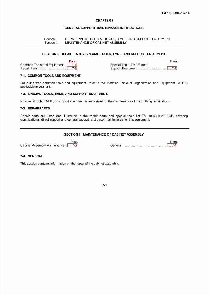
8/7/2019 TM 10-3530-205-10 CLOTHING REPAIR SHOP
http://slidepdf.com/reader/full/tm-10-3530-205-10-clothing-repair-shop 395/455
TM 10-3530-205-14
CHAPTER 7
GENERAL SUPPORT MAINTENANCE INSTRUCTIONS
Section I. REPAIR PARTS, SPECIAL TOOLS, TMDE, AND SUPPORT EQUIPMENTSection II. MIAINTENANCE OF CABINET ASSEMBLY
SECTION I. REPAIR PARTS, SPECIAL TOOLS, TMDE, AND SUPPORT EQUIPMENT
Para. Para.Common Tools and Equipment.... .... 7-1 Special Tools, TMDE, andRepair Parts................................ . .... 7-3 Support Equipment ................................ . .... 7-2
7-1. C OMMON TOOLS AND EQUIPMENT.
For authorized common tools and equipment, refer to the Modified Table of Organization and Equipment (MTOE)applicable to your unit.
7-2. S PECIAL TOOLS, TMDE, AND SUPPORT EQUIPMENT.No special tools, TMDE, or support equipment is authorized for the maintenance of the clothing repair shop.
7-3. R EPAIRPARTS.
Repair parts are listed and illustrated in the repair parts and special tools list TM 10-3530-205-24P, coveringorganizational, direct support and general support, and depot maintenance for this equipment.
SECTION II. MAINTENANCE OF CABINET ASSEMBLY
Para. Para.Cabinet Assembly Maintenance... .... 7-5 General................................. .................. .... 7-4
7-4. G ENERAL.
This section contains information on the repair of the cabinet assembly.
7-1
8/7/2019 TM 10-3530-205-10 CLOTHING REPAIR SHOP
http://slidepdf.com/reader/full/tm-10-3530-205-10-clothing-repair-shop 396/455
TM 10-3530-205-14
7-5. C ABINET ASSEMBLY MAINTENANCE.
This task covers: b. Repair of Frameworka. Repair of Holes and Dents d. Repair of Holddown Clamps
INITIAL SETUP Equipment
ConditionApplicable Configuration Para. Condition DescriptionAll 2-9 All equipment removed
from cabinet.Test Equipment
None Special Environmental ConditionsNone
Special ToolsRiveting Tool Set General Safety InstructionsWelding Set (for Aluminum) NonePaint Spraying Equipment
Personnel RequiredMaterial/Parts 2 Persons
RivetsAluminum Sheet Metal (Patches)Primer, Zinc Chromate
(Appendix E , item 7)Paint, Olive Drab
(Appendix E , item 6)Sealing Compound
(Appendix E , item 8)
a. Repair of Holes and Dents.
(1) Dents.
(a) Push out all dents. (If damage is too great to push out, treat as if it were a hole. Refer to para. 7-5 a.(2) below).
(b) Sand area with sandpaper and refinish with primer (Appendix E , item 7) and olive drab paint(Appendix E, item 6).
(2) Holes.
(a) Cut away the affected areas to remove all jagged edges. If metal is bent, straighten.
(b) Sand both sides of the area with sandpaper to remove all sharp edges.
(c) Apply one coat of primer (Appendix E , item 7) to both sides of the sheet metal.
GO TO NEXT PAGE
7-2
8/7/2019 TM 10-3530-205-10 CLOTHING REPAIR SHOP
http://slidepdf.com/reader/full/tm-10-3530-205-10-clothing-repair-shop 397/455
TM 10-3530-205-14
7-5. CABINET ASSEMBLY MAINTENANCE - Continued.
a. Repair of Holes and Dents - Continued.
(2) Holes - Continued.
(d) Cut two patches that are alike. Be sure that they extend at least 1 inch (2.54 cm) over the edges of
the hole all the way around.(e) Place the patches in position and drill holes not further than 1-1/2 inches (3.18 cm) apart for mounting
the rivets.
(f) Apply one coat of primer (Appendix E , item 7) to both sides of the patches and allow to dry.
(g) Apply sealing compound (Appendix E , item 8) between both patches and the sheet metal.
(h) Install the patches with rivets.
(i) Refinish both the inside and outside of the primered and patched area with olive drab paint (AppendixE, item 6).
b. Repair of Framework.
(1) Remove all paint from at least 4 inches (10 cm) on each side of the damaged area.
(2) Cut away the damaged area if bent or twisted. Cut away several inches away from a break. If the frame iscracked, the area does not have to be cut away.
(3) Cut a new piece of material of the same size and shape as the frame piece to be repaired.
(4) Place the new piece into position and weld into place. If frame was cracked, weld the crack usingaluminum techniques.
(5) Refinish the repaired area with primer (Appendix E , item 7) and olive drab paint (Appendix E, item 6).
c. Repair of Holddown Clamps . Repair of the holddown clamps is limited to the welding of broken or cracked partsusing stainless steel welding techniques.
END OF TASK
7-3/7-4 Blank

8/7/2019 TM 10-3530-205-10 CLOTHING REPAIR SHOP
http://slidepdf.com/reader/full/tm-10-3530-205-10-clothing-repair-shop 398/455
8/7/2019 TM 10-3530-205-10 CLOTHING REPAIR SHOP
http://slidepdf.com/reader/full/tm-10-3530-205-10-clothing-repair-shop 399/455
TM 10-3530-205-14
APPENDIX A
REFERENCES
A-1. SCOPE.
This appendix lists all forms, field manuals, technical manuals, and miscellaneous publications referenced in this manual.
A-2. FORMS.
Equipment Improvement Recommendations ................................ ........... SF 368
Equipment Inspection and Maintenance WorkSheet................................ ................................ ............................. DA Form 2404
Recommended Changes to Equipment TechnicalManuals................................ ................................ ......................... DA Form 2028-2
Recommended Changes to Publications andBlank Forms ................................ ................................ .................. DA Form 2028
Maintenance Request................................ ................................ .............. DA Form 2407
Packaging Improvement Report ................................ .............................. DD Form 6
A-3. FIELD MANUALS.
First Aid for Soldiers ................................ ................................ ............... FM 21-11
A-4. TECHNICAL MANUALS.Administrative Storage or Equipment ................................ ...................... TM 740-90-1
Lubrication Order ................................ ................................ .................... LO 10-3530-205-12-1LO 10-3530-205-12-2LO 10-3530-205-12-3LO 10-3530-205-12-4
Operation and Maintenance of OrdinanceEquipment in Cold Weather (0° to -65 ° F,
-18°to -54 ° F)................................ ................................ ................. TM 9-207
Operator, Organizational, Direct Support andGeneral Support Maintenance Manual for Gener-ator Set, Gasoline Engine, Military Design(Less Engine), 3 KW, AC, 60 Hz, DoD Model MEP-016A, NSN 6115-00-017-8237................................ ................................ TM 5-6115-271-14
A-1
8/7/2019 TM 10-3530-205-10 CLOTHING REPAIR SHOP
http://slidepdf.com/reader/full/tm-10-3530-205-10-clothing-repair-shop 400/455
TM 10-3530-205-14
Organizational, Direct and General SupportRepair Parts and Special Tools List forGenerator Set, Gasoline Engine, MilitaryDesign (Less Engine), 3 KW, AC, 60 Hz,DoD Model , MEP-016A, NSN 6105-00-017-8237................................ ... TM 5-6115-271-24P
A-4. TECHNICAL MANUALS - Continued.
Operator, Organizational, Direct Support andGeneral Support Maintenance Manual for Trailer,Cargo, 1 1/2 Ton, 2-Wheel, M105A2, NSN 2330-00-141-8050................................ ................................ ............................ TM 9-2330-213-14
Procedures for Destruction of Equipment toPrevent Enemy Use ................................ ................................ ................ TM 750-244-3
The Army Maintenance Management System................................ ......... DA PAM 738-750
Organizational, Direct Support and GeneralSupport Repair Parts and Special Tools List(Including Depot Maintenance Repair Partand Special Tools) ................................ ................................ ................. TM 10-3530-205-24P
Tent, General Purpose (Small, Medium, andLarge) ................................ ................................ ................................ ..... TM 10-8340-211-13
A-5. TECHNICAL BULLETINS.
Index of Technical Publications................................ ............................... DA PAM 310-1
Preservation and Storage of Mechanical Equipmentfor Shipment and Storage ................................ ................................ ....... TB 740-97-2
A-2
8/7/2019 TM 10-3530-205-10 CLOTHING REPAIR SHOP
http://slidepdf.com/reader/full/tm-10-3530-205-10-clothing-repair-shop 401/455
TM 10-3530-205-14
APPENDIX B
MAINTENANCE ALLOCATION CHART (MAC)
B-1 C hange 3
SECTION I. INTRODUCTION
B-1. The Army Maintenance System MAC
This introduction provides a general explanation of all maintenance and repair functions authorized at thetwo maintenance levels under the Two-Level Maintenance System concept.
This MAC (immediately following the introduction) designates overall authority and responsibility for theperformance of maintenance functions on the identified end item or component. The application of themaintenance functions to the end item or component levels, which are shown on the MAC in column (4)as:
Field - includes two columns, Unit Maintenance and Direct Support maintenance. The Unitmaintenance column is divided again into two more subcolumns, C for Operator or Crew and O forUnit maintenance.
Sustainment – includes two subcolumns, general support (H) and depot (D).
The tools and test equipment requirements (immediately following the MAC) list the tools and testequipment (both special tools and common tool sets) required for each maintenance function asreferenced from the MAC.
The remarks (immediately following the tools and test equipment requirements) contain supplementalinstructions and explanatory notes for a particular maintenance function.
B-2. Maintenance Functions
Maintenance functions will be limited to and are defined as follows:
1. Inspect . To determine the serviceability of an item by comparing its physical, mechanical, and/orelectrical characteristics with established standards through examination (e.g., by sight, sound, orfeel.) This includes scheduled inspection and gagings and evaluation of cannon tubes.
2. Test. To verify serviceability by measuring the mechanical, pneumatic, hydraulic, or electricalcharacteristics of an item and comparing those characteristics with prescribed standards on ascheduled basis, i.e., load testing of lift devices and hydrostatic testing of pressure hoses.
3. Service. Operations required periodically to keep an item in proper operating condition; e.g., toclean (includes decontaminate, when required), to preserve, to drain, to paint, or to replenish fuel,lubricants, chemical fluids, or gases. This includes scheduled exercising and purging of recoilmechanisms. The following are examples of service functions:
a. Unpack. To remove from packing box for service or when required for the performance ofmaintenance operations.
b. Repack. To return item to packing box after service and other maintenance operations.
c. Clean. To rid the item of contamination.
8/7/2019 TM 10-3530-205-10 CLOTHING REPAIR SHOP
http://slidepdf.com/reader/full/tm-10-3530-205-10-clothing-repair-shop 402/455
TM 10-3530-205-14
Change 3 B-2
d. Touch up. To spot paint scratched or blistered surfaces.
e. Mark. To restore obliterated identification.
4. Adjust. To maintain or regulate, within prescribed limits, by bringing into proper position, or bysetting the operating characteristics to specified parameters.
5. Align. To adjust specified variable elements of an item to bring about optimum or desiredperformance
6. Calibrate. To determine and cause corrections to be made or to be adjusted on instruments of test,measuring, and diagnostic equipment used in precision measurement. Consists of comparisons oftwo instruments, one of which is a certified standard of known accuracy, to detect and adjust anydiscrepancy in the accuracy of the instrument being compared.
7. Remove/install. To remove and install the same item when required to perform service or othermaintenance functions. Install may be the act of emplacing, seating, or fixing into position a spare,repair part, or module (component or assembly) in a manner to allow the proper functioning of anequipment or system.
8. Paint. To prepare and spray color coats of paint so that the ammunition can be identified andprotected. The color indicating primary use is applied, preferably, to the entire exterior surface asthe background color of the item. Other markings are to be repainted as original so as to retainproper ammunition identification.
9. Replace. To remove an unserviceable item and install a serviceable counterpart in its place.“Replace” is authorized by the MAC and assigned maintenance level is shown as the third positioncode of the Source, Maintenance and Recoverability (SMR) code.
10. Repair. The application of maintenance services, including fault location/troubleshooting,removal/installation, disassembly/assembly procedures and maintenance actions to identifytroubles and restore serviceability to an item by correcting specific damage, fault, malfunction, orfailure in a part, subassembly, module (component or assembly), end item, or system.
NOTE
The following definitions are applicable to the “repair” maintenance function: Services.Inspect, test, service, adjust, align, calibrate, and/or replace.
Fault location/troubleshooting. The process of investigating and detecting the cause ofequipment malfunctioning; the act of isolating a fault within a system or Unit Under Test(UUT).
Disassembly/assembly. The step-by-step breakdown (taking apart) of a spare/functional group
coded item to the level of its least component, that is assigned an SMR code for the level ofmaintenance under consideration (i.e. identified as maintenance significant).
Actions. Welding, grinding, riveting, straightening, facing, machining, and/or resurfacing.
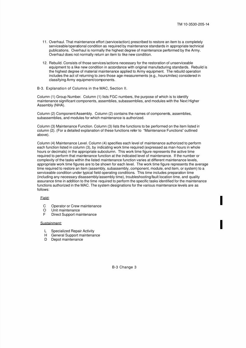
8/7/2019 TM 10-3530-205-10 CLOTHING REPAIR SHOP
http://slidepdf.com/reader/full/tm-10-3530-205-10-clothing-repair-shop 403/455
TM 10-3530-205-14
B-3 Change 3
11. Overhaul. That maintenance effort (service/action) prescribed to restore an item to a completelyserviceable/operational condition as required by maintenance standards in appropriate technicalpublications. Overhaul is normally the highest degree of maintenance performed by the Army.
Overhaul does not normally return an item to like new condition.12. Rebuild. Consists of those services/actions necessary for the restoration of unserviceable
equipment to a like new condition in accordance with original manufacturing standards. Rebuild isthe highest degree of material maintenance applied to Army equipment. The rebuild operationincludes the act of returning to zero those age measurements (e.g., hours/miles) considered inclassifying Army equipment/components.
B-3. Explanation of Columns in the MAC, Section II.
Column (1) Group Number. Column (1) lists FGC numbers, the purpose of which is to identifymaintenance significant components, assemblies, subassemblies, and modules with the Next HigherAssembly (NHA).
Column (2) Component/Assembly. Column (2) contains the names of components, assemblies,subassemblies, and modules for which maintenance is authorized.
Column (3) Maintenance Function. Column (3) lists the functions to be performed on the item listed incolumn (2). (For a detailed explanation of these functions refer to “Maintenance Functions” outlinedabove).
Column (4) Maintenance Level. Column (4) specifies each level of maintenance authorized to performeach function listed in column (3), by indicating work time required (expressed as man-hours in wholehours or decimals) in the appropriate subcolumn. This work time figure represents the active timerequired to perform that maintenance function at the indicated level of maintenance. If the number orcomplexity of the tasks within the listed maintenance function varies at different maintenance levels,appropriate work time figures are to be shown for each level. The work time figure represents the average
time required to restore an item (assembly, subassembly, component, module, end item, or system) to aserviceable condition under typical field operating conditions. This time includes preparation time(including any necessary disassembly/assembly time), troubleshooting/fault location time, and qualityassurance time in addition to the time required to perform the specific tasks identified for the maintenancefunctions authorized in the MAC. The system designations for the various maintenance levels are asfollows:
Field:
Sustainment:
C Operator or Crew maintenanceO Unit maintenanceF Direct Support maintenance
L Specialized Repair ActivityH General Support maintenanceD Depot maintenance
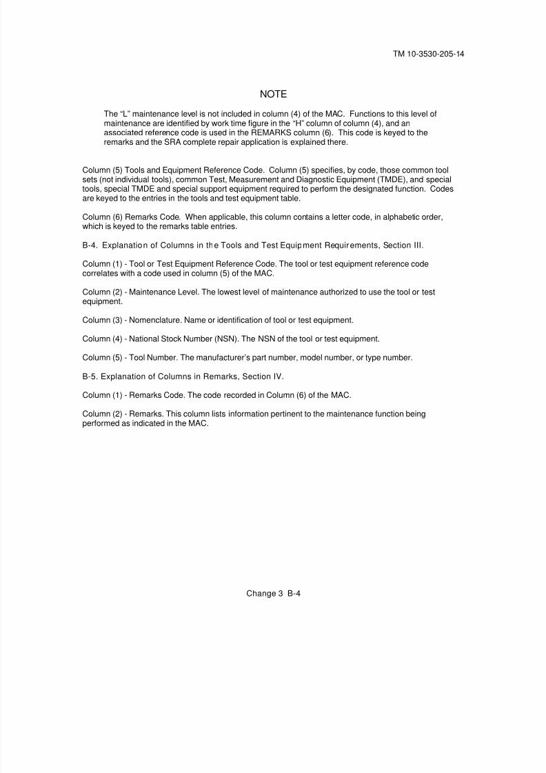
8/7/2019 TM 10-3530-205-10 CLOTHING REPAIR SHOP
http://slidepdf.com/reader/full/tm-10-3530-205-10-clothing-repair-shop 404/455
TM 10-3530-205-14
Change 3 B-4
NOTE
The “L” maintenance level is not included in column (4) of the MAC. Functions to this level of
maintenance are identified by work time figure in the “H” column of column (4), and anassociated reference code is used in the REMARKS column (6). This code is keyed to theremarks and the SRA complete repair application is explained there.
Column (5) Tools and Equipment Reference Code. Column (5) specifies, by code, those common toolsets (not individual tools), common Test, Measurement and Diagnostic Equipment (TMDE), and specialtools, special TMDE and special support equipment required to perform the designated function. Codesare keyed to the entries in the tools and test equipment table.
Column (6) Remarks Code. When applicable, this column contains a letter code, in alphabetic order,which is keyed to the remarks table entries.
B-4. Explanation of Columns in the Tools and Test Equipment Requir ements, Section III.Column (1) - Tool or Test Equipment Reference Code. The tool or test equipment reference codecorrelates with a code used in column (5) of the MAC.
Column (2) - Maintenance Level. The lowest level of maintenance authorized to use the tool or testequipment.
Column (3) - Nomenclature. Name or identification of tool or test equipment.
Column (4) - National Stock Number (NSN). The NSN of the tool or test equipment.
Column (5) - Tool Number. The manufacturer’s part number, model number, or type number.
B-5. Explanation of Columns in Remarks, Section IV.
Column (1) - Remarks Code. The code recorded in Column (6) of the MAC.
Column (2) - Remarks. This column lists information pertinent to the maintenance function beingperformed as indicated in the MAC.
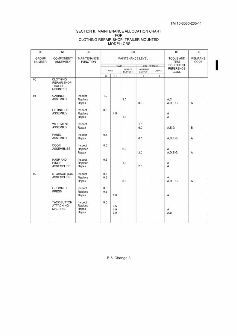
8/7/2019 TM 10-3530-205-10 CLOTHING REPAIR SHOP
http://slidepdf.com/reader/full/tm-10-3530-205-10-clothing-repair-shop 405/455
TM 10-3530-205-14
B-5 C hange 3
SECTION II. MAINTENANCE ALL OCATION CHARTFOR
CLOTHING REPAIR SHOP, TRAILER MOUNTEDMODEL: CRS
(4)
MAINTENANCE LEVEL
(1)
GROUPNUMBER
FIELD SUSTAINMENT
(2)
COMPONENT/ ASSEMBLY
(3)
MAINTENANCEFUNCTION
UNIT DIRECTSUPPORT
GENERALSUPPORT DEPOT
(5)
TOOLS ANDTEST
EQUIPMENTREFERENCE
CODE
(6)
REMARKSCODE
C O F H D00 CLOTHING
REPAIR SHOPTRAILERMOUNTED
01 Inspect 1.0Replace 3.0 A,C
CABINETASSEMBLY
Repair 8.0 A,D,E,G A
Inspect 0.5Replace 1.5 A
LIFTING EYEASSEMBLY
Repair 1.5 A
Inspect 1.0WELDMENTASSEMBLY Repair 6.0 A,E,G B
Inspect 0.5PANELASSEMBLY Repair 6.0 A,D,E,G A
Inspect 0.5Replace 2.0 A
DOORASSEMBLIES
Repair 2.0 A,D,E,G A
0.51.0
HASP ANDHINGEASSEMBLIES`
InspectReplaceRepair 2.0
AA
02 Inspect 0.5 Replace 0.5 A
STORAGE BOXASSEMBLIES
Repair 3.0 A,D,E,G A
Inspect 0.5 Replace 0.5
GROMMETPRESS
Repair 1.0 A
0.50.5
TACK BUTTONATTACHINGMACHINE
InspectReplaceRepairRepair
1.03.0
AA,B
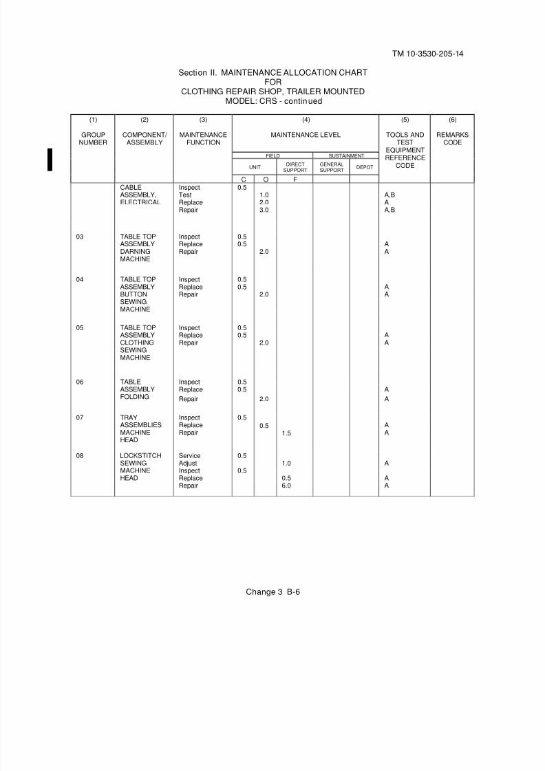
8/7/2019 TM 10-3530-205-10 CLOTHING REPAIR SHOP
http://slidepdf.com/reader/full/tm-10-3530-205-10-clothing-repair-shop 406/455
TM 10-3530-205-14
Change 3 B-6
Section II. MAINTENANCE ALLOCATION CHARTFOR
CLOTHING REPAIR SHOP, TRAILER MOUNTEDMODEL: CRS - contin ued
(4)
MAINTENANCE LEVEL
(3)
MAINTENANCEFUNCTION
FIELD SUSTAINMENT
(1)
GROUPNUMBER
(2)
COMPONENT/ ASSEMBLY
UNIT DIRECTSUPPORT
GENERALSUPPORT DEPOT
(5)
TOOLS ANDTEST
EQUIPMENTREFERENCE
CODE
C O F
(6)
REMARKSCODE
0.5CABLEASSEMBLY,ELECTRICAL
InspectTestReplaceRepair
1.02.03.0
A,BAA,B
03 0.5 0.5
TABLE TOPASSEMBLYDARNINGMACHINE
InspectReplaceRepair 2.0
AA
04 0.5 0.5
TABLE TOPASSEMBLYBUTTONSEWINGMACHINE
InspectReplaceRepair 2.0
AA
05 0.5 0.5
TABLE TOPASSEMBLYCLOTHINGSEWINGMACHINE
InspectReplaceRepair 2.0
AA
06 Inspect 0.5 Replace 0.5 A
TABLEASSEMBLYFOLDING Repair 2.0 A
07 TRAYASSEMBLIESMACHINEHEAD
InspectReplaceRepair
0.5 0.5
1.5AA
08 LOCKSTITCHSEWINGMACHINEHEAD
ServiceAdjustInspectReplaceRepair
0.5
0.5 1.0
0.56.0
A
AA
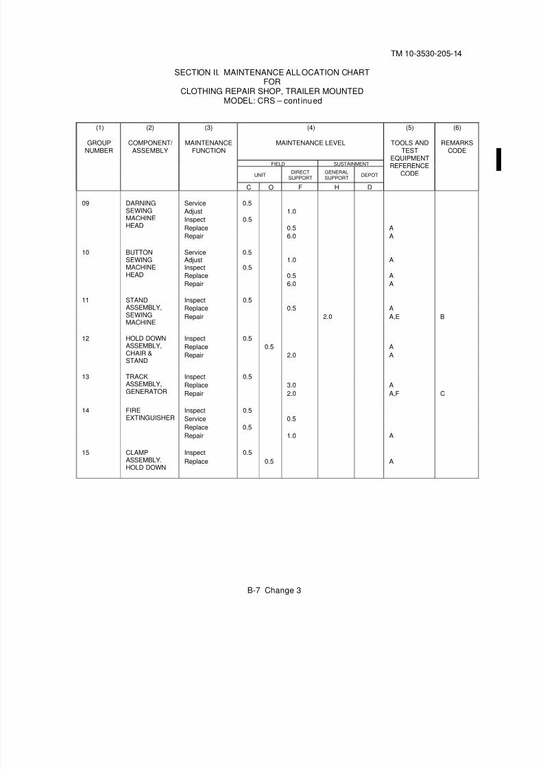
8/7/2019 TM 10-3530-205-10 CLOTHING REPAIR SHOP
http://slidepdf.com/reader/full/tm-10-3530-205-10-clothing-repair-shop 407/455
TM 10-3530-205-14
B-7 C hange 3
SECTION II. MAINTENANCE ALL OCATION CHARTFOR
CLOTHING REPAIR SHOP, TRAILER MOUNTEDMODEL: CRS – cont inued
(4)
MAINTENANCE LEVEL
(3)
MAINTENANCEFUNCTION
FIELD SUSTAINMENT
(1)
GROUPNUMBER
UNIT DIRECTSUPPORT
GENERALSUPPORT DEPOT
(5)
TOOLS ANDTEST
EQUIPMENTREFERENCE
CODE
(2)
COMPONENT/ ASSEMBLY
C O F H D
(6)
REMARKSCODE
09 Service 0.5 Adjust 1.0Inspect 0.5 Replace 0.5 A
DARNINGSEWINGMACHINEHEAD
Repair 6.0 A
10 Service 0.5 Adjust 1.0 AInspect 0.5 Replace 0.5 A
BUTTONSEWINGMACHINEHEAD
Repair 6.0 A
11 Inspect 0.5 Replace 0.5 A
STANDASSEMBLY,SEWINGMACHINE
Repair 2.0 A,E B
12 Inspect 0.5 Replace 0.5 A
HOLD DOWNASSEMBLY,CHAIR &STAND
Repair 2.0 A
13 Inspect 0.5 Replace 3.0 A
TRACKASSEMBLY,GENERATOR Repair 2.0 A,F C
14 Inspect 0.5 Service 0.5Replace 0.5
FIREEXTINGUISHER
Repair 1.0 A
15 Inspect 0.5 CLAMPASSEMBLY,HOLD DOWN
Replace 0.5 A
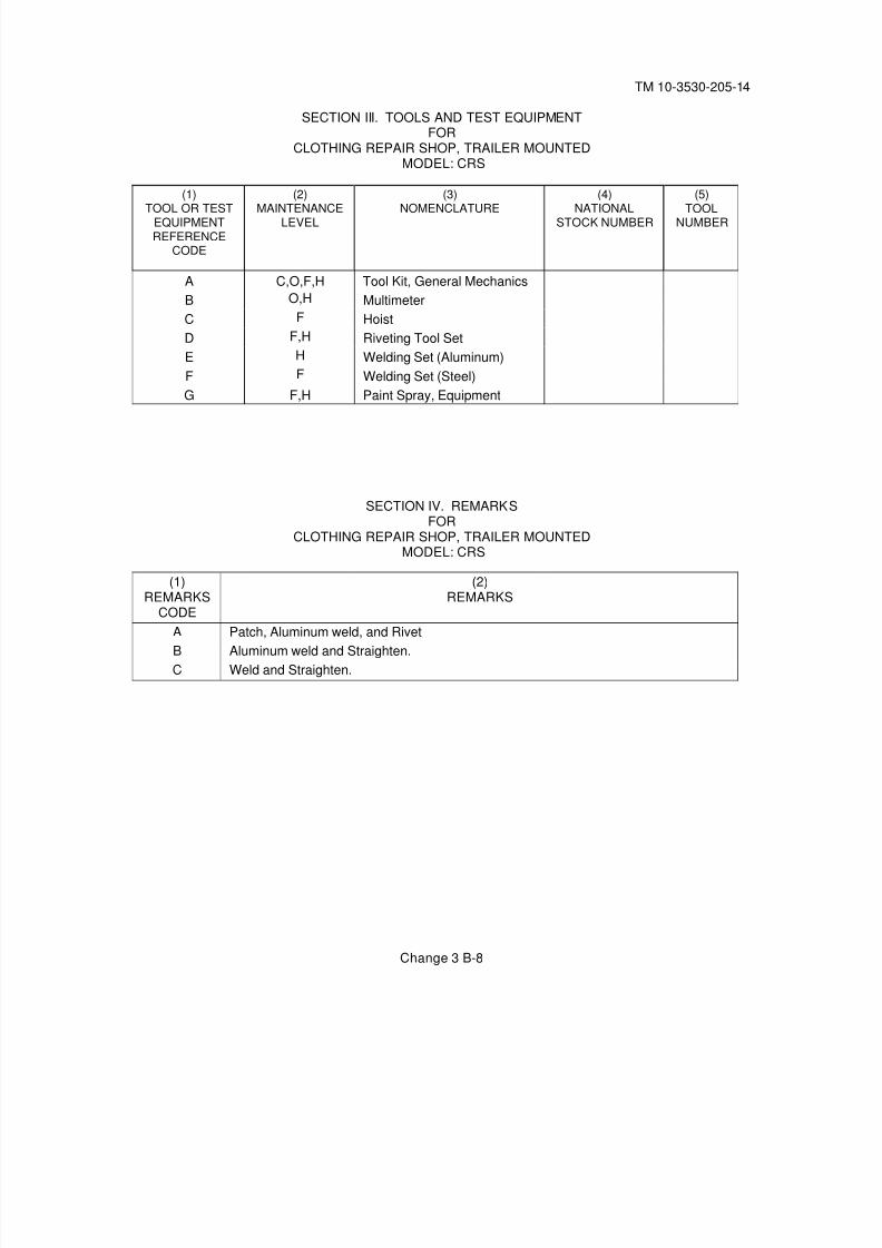
8/7/2019 TM 10-3530-205-10 CLOTHING REPAIR SHOP
http://slidepdf.com/reader/full/tm-10-3530-205-10-clothing-repair-shop 408/455
TM 10-3530-205-14
Change 3 B-8
SECTION III. TOOLS AND TEST EQUIPMENTFOR
CLOTHING REPAIR SHOP, TRAILER MOUNTEDMODEL: CRS
(1)TOOL OR TEST
EQUIPMENTREFERENCE
CODE
(2)MAINTENANCE
LEVEL
(3)NOMENCLATURE
(4)NATIONAL
STOCK NUMBER
(5)TOOL
NUMBER
A C,O,F,H Tool Kit, General MechanicsB O,H MultimeterC F HoistD F,H Riveting Tool SetE H Welding Set (Aluminum)F F Welding Set (Steel)G F,H Paint Spray, Equipment
SECTION IV. REMARKSFOR
CLOTHING REPAIR SHOP, TRAILER MOUNTEDMODEL: CRS
(1)
REMARKSCODE
(2)
REMARKS
A Patch, Aluminum weld, and RivetB Aluminum weld and Straighten.C Weld and Straighten.
8/7/2019 TM 10-3530-205-10 CLOTHING REPAIR SHOP
http://slidepdf.com/reader/full/tm-10-3530-205-10-clothing-repair-shop 409/455
TM 10-3530-205-14
APPENDIX C
COMPONENTS OF END ITEMAND BASIC ISSUE ITEMS LIST
SECTION I. INTRODUCTION
C-1. SCOPE.
This appendix lists components of end item and basic issue items for the clothing repair shop to help you inventory itemsrequired for safe and efficient operation.
C-2. GENERAL.
The Components of End Item and Basic Issue Item Lists are divided into the following sections:
a. Section II. Components of End Item. This listing is for information purposes only, and is not authority torequisition replacements. These items are part of the end item, but are removed and separately packaged fortransportation or shipment. As part of the end item, these items must be with the end item whenever it is issued or
transferred between property accounts. Illustrations are furnished to assist you in identifying the items.
b. Section III. Basic Issue Items. These are the minimum essential items required to place the clothing repairshop in operation, to operate it, and to perform emergency repairs. Although shipped separately packaged, the basicissue items (BII) must be with the clothing repair shop during operation and whenever it is transferred between propertyaccounts. The illustrations will assist you with hard-to-identify items. This manual is your authority to request/requisitionreplacement BII, based on TOE/MTOE authorization of the end item.
C- 3. EXPLANATION OF COLUMNS.
a. Column (1) - Illustration Number (Illus Number). This column indicates the number of the illustration in whichthe item is shown.
b. Column (2) - National Stock Number. Indicates the National stock
c. Column (3) - Description. Indicates the Federal item name and, if required, a minimum description to identifyand locate the item. The last line for each item indicates the FSCM (in parentheses) followed by the part number.
d. Column (4) - Unit of Measure (U/M). Indicates the measure used in performing the actualoperational/maintenance function. This measure is ex- pressed by a two-character alphabetical abbreviation (e.g., ea,in, pr).
e. Column (5) - Quantity required (Qty rqr). Indicates the quantity of the item authorized to be used with/on theequipment.
C-1
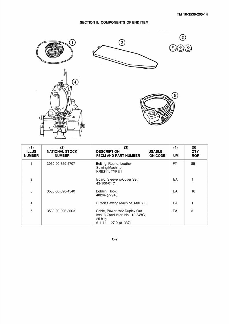
8/7/2019 TM 10-3530-205-10 CLOTHING REPAIR SHOP
http://slidepdf.com/reader/full/tm-10-3530-205-10-clothing-repair-shop 410/455
TM 10-3530-205-14
SECTION II. COMPONENTS OF END ITEM
(1) (2) (3) (4) (5)ILLUS NATIONAL STOCK DESCRIPTION USABLE QTY
NUMBER NUMBER FSCM AND PART NUMBER ON CODE UM RQR1 3030-00-359-5707 Belting, Round, Leather FT 85
Sewing MachineKRB211, TYPE I
2 Board, Sleeve w/Cover Set EA 143-100-01 (*)
3 3530-00-390-4540 Bobbin, Hook EA 1840264 (77948)
4 Button Sewing Machine, Mdl 600 EA 1
5 3530-00-906-8063 Cable, Power, w/2 Duplex Out- EA 3lets, 3-Conductor, No. 12 AWG,25 ft lg6-1-1111-27-9 (81337)
C-2
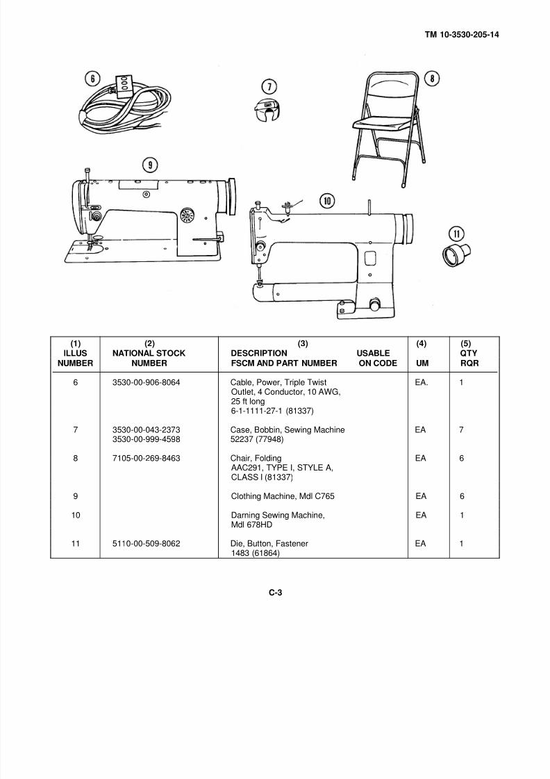
8/7/2019 TM 10-3530-205-10 CLOTHING REPAIR SHOP
http://slidepdf.com/reader/full/tm-10-3530-205-10-clothing-repair-shop 411/455
TM 10-3530-205-14
(1) (2) (3) (4) (5)ILLUS NATIONAL STOCK DESCRIPTION USABLE QTY
NUMBER NUMBER FSCM AND PART NUMBER ON CODE UM RQR
6 3530-00-906-8064 Cable, Power, Triple Twist EA. 1Outlet, 4 Conductor, 10 AWG,25 ft long6-1-1111-27-1 (81337)
7 3530-00-043-2373 Case, Bobbin, Sewing Machine EA 73530-00-999-4598 52237 (77948)
8 7105-00-269-8463 Chair, Folding EA 6AAC291, TYPE I, STYLE A,CLASS I (81337)
9 Clothing Machine, Mdl C765 EA 6
10 Darning Sewing Machine, EA 1Mdl 678HD
11 5110-00-509-8062 Die, Button, Fastener EA 11483 (61864)
C-3
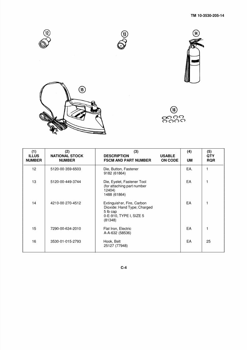
8/7/2019 TM 10-3530-205-10 CLOTHING REPAIR SHOP
http://slidepdf.com/reader/full/tm-10-3530-205-10-clothing-repair-shop 412/455
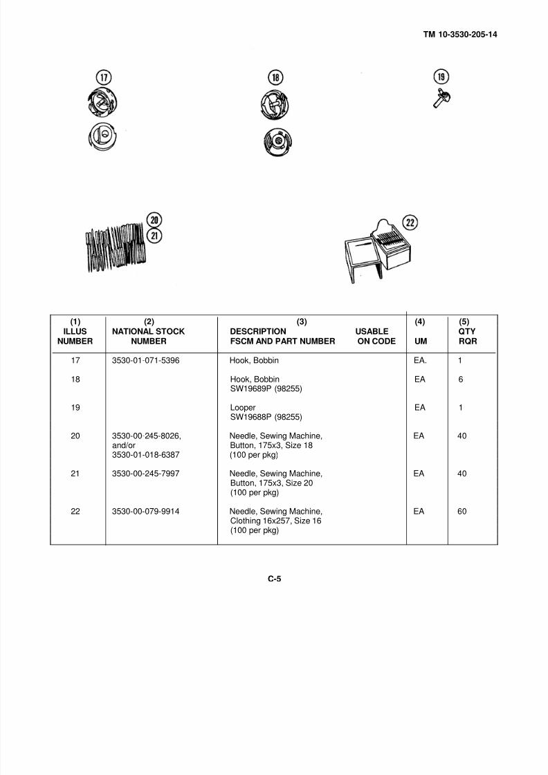
8/7/2019 TM 10-3530-205-10 CLOTHING REPAIR SHOP
http://slidepdf.com/reader/full/tm-10-3530-205-10-clothing-repair-shop 413/455
TM 10-3530-205-14
(1) (2) (3) (4) (5)ILLUS NATIONAL STOCK DESCRIPTION USABLE QTY
NUMBER NUMBER FSCM AND PART NUMBER ON CODE UM RQR
17 3530-01-071-5396 Hook, Bobbin EA. 1
18 Hook, Bobbin EA 6SW19689P (98255)
19 Looper EA 1SW19688P (98255)
20 3530-00-245-8026, Needle, Sewing Machine, EA 40and/or Button, 175x3, Size 183530-01-018-6387 (100 per pkg)
21 3530-00-245-7997 Needle, Sewing Machine, EA 40Button, 175x3, Size 20(100 per pkg)
22 3530-00-079-9914 Needle, Sewing Machine, EA 60Clothing 16x257, Size 16(100 per pkg)
C-5
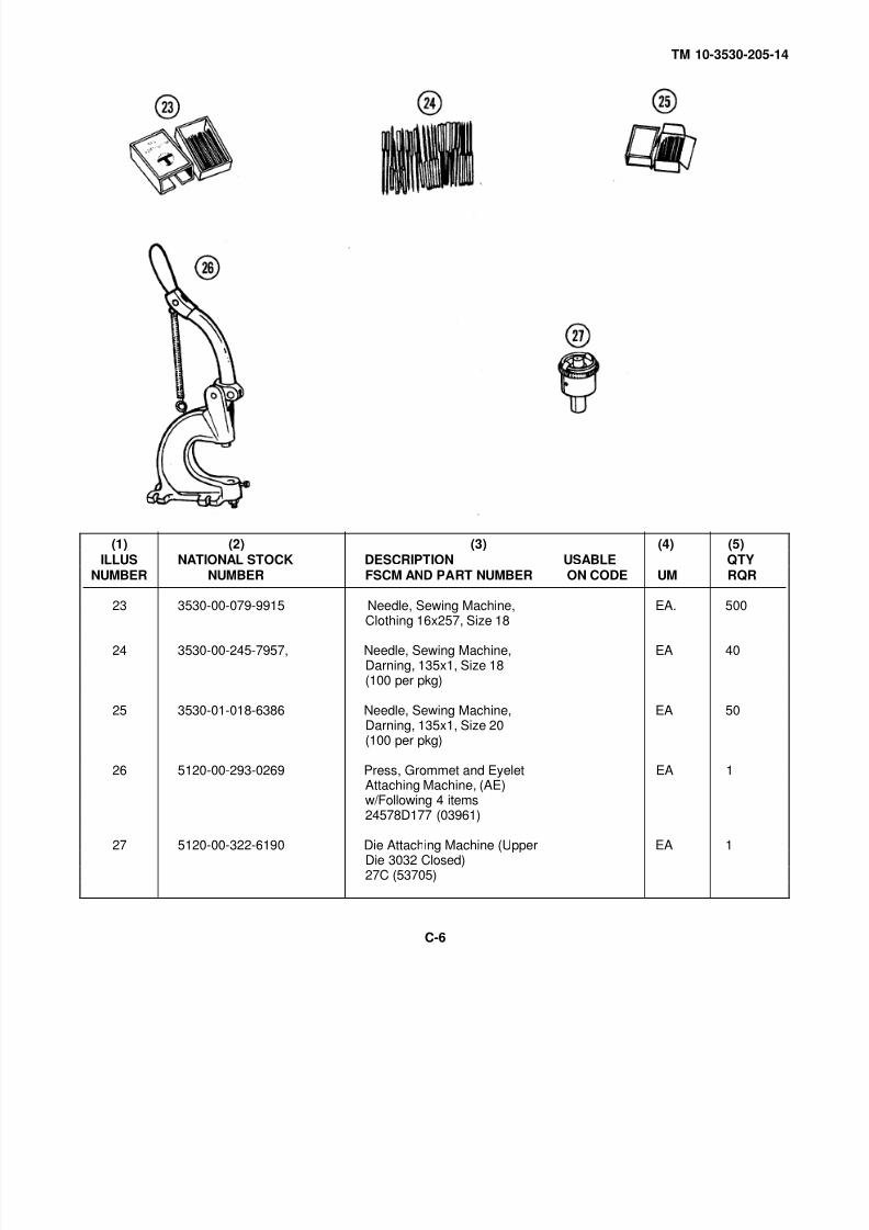
8/7/2019 TM 10-3530-205-10 CLOTHING REPAIR SHOP
http://slidepdf.com/reader/full/tm-10-3530-205-10-clothing-repair-shop 414/455
TM 10-3530-205-14
(1) (2) (3) (4) (5)ILLUS NATIONAL STOCK DESCRIPTION USABLE QTY
NUMBER NUMBER FSCM AND PART NUMBER ON CODE UM RQR
23 3530-00-079-9915 Needle, Sewing Machine, EA. 500Clothing 16x257, Size 18
24 3530-00-245-7957, Needle, Sewing Machine, EA 40Darning, 135x1, Size 18(100 per pkg)
25 3530-01-018-6386 Needle, Sewing Machine, EA 50Darning, 135x1, Size 20(100 per pkg)
26 5120-00-293-0269 Press, Grommet and Eyelet EA 1Attaching Machine, (AE)w/Following 4 items24578D177 (03961)
27 5120-00-322-6190 Die Attaching Machine (Upper EA 1Die 3032 Closed)27C (53705)
C-6
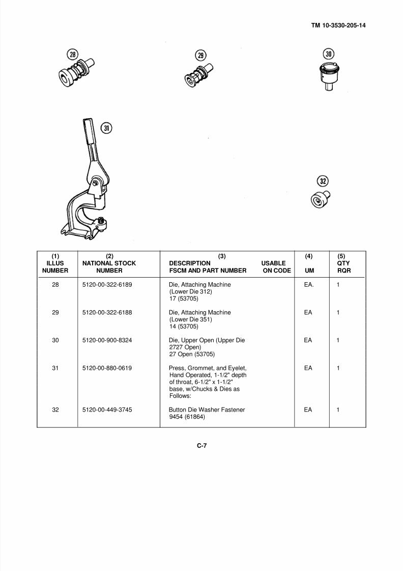
8/7/2019 TM 10-3530-205-10 CLOTHING REPAIR SHOP
http://slidepdf.com/reader/full/tm-10-3530-205-10-clothing-repair-shop 415/455
TM 10-3530-205-14
(1) (2) (3) (4) (5)ILLUS NATIONAL STOCK DESCRIPTION USABLE QTY
NUMBER NUMBER FSCM AND PART NUMBER ON CODE UM RQR
28 5120-00-322-6189 Die, Attaching Machine EA. 1(Lower Die 312)17 (53705)
29 5120-00-322-6188 Die, Attaching Machine EA 1(Lower Die 351)14 (53705)
30 5120-00-900-8324 Die, Upper Open (Upper Die EA 12727 Open)27 Open (53705)
31 5120-00-880-0619 Press, Grommet, and Eyelet, EA 1Hand Operated, 1-1/2" depthof throat, 6-1/2" x 1-1/2"base, w/Chucks & Dies asFollows:
32 5120-00-449-3745 Button Die Washer Fastener EA 19454 (61864)
C-7
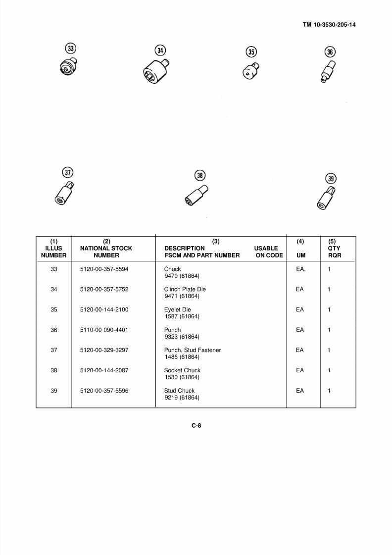
8/7/2019 TM 10-3530-205-10 CLOTHING REPAIR SHOP
http://slidepdf.com/reader/full/tm-10-3530-205-10-clothing-repair-shop 416/455
TM 10-3530-205-14
(1) (2) (3) (4) (5)ILLUS NATIONAL STOCK DESCRIPTION USABLE QTY
NUMBER NUMBER FSCM AND PART NUMBER ON CODE UM RQR
33 5120-00-357-5594 Chuck EA. 19470 (61864)
34 5120-00-357-5752 Clinch Plate Die EA 19471 (61864)
35 5120-00-144-2100 Eyelet Die EA 11587 (61864)
36 5110-00-090-4401 Punch EA 19323 (61864)
37 5120-00-329-3297 Punch, Stud Fastener EA 1
1486 (61864)
38 5120-00-144-2087 Socket Chuck EA 11580 (61864)
39 5120-00-357-5596 Stud Chuck EA 19219 (61864)
C-8
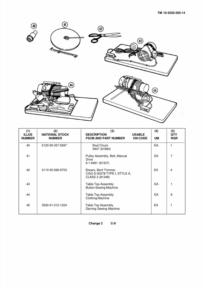
8/7/2019 TM 10-3530-205-10 CLOTHING REPAIR SHOP
http://slidepdf.com/reader/full/tm-10-3530-205-10-clothing-repair-shop 417/455
TM 10-3530-205-14
(1) (2) (3) (4) (5)ILLUS NATIONAL STOCK DESCRIPTION USABLE QTY
NUMBER NUMBER FSCM AND PART NUMBER ON CODE UM RQR
40 5120-00-357-5597 Stud Chuck EA. 19447 (61864)
41 Pulley Assembly, Belt, Manual EA 7Drive6-1-6461 (81337)
42 5110-00-596-9703 Shears, Bent Trimmer EA 4CGG-S-00278 TYPE I, STYLE A,CLASS 2 (81348)
43 Table Top Assembly EA 1Button Sewing Machine
44 Table Top Assembly EA 6Clothing Machine
45 3530-01-212-1224 Table Top Assembly EA 1Darning Sewing Machine
Change 2 C-9
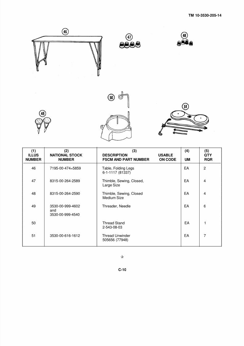
8/7/2019 TM 10-3530-205-10 CLOTHING REPAIR SHOP
http://slidepdf.com/reader/full/tm-10-3530-205-10-clothing-repair-shop 418/455
TM 10-3530-205-14
(1) (2) (3) (4) (5)ILLUS NATIONAL STOCK DESCRIPTION USABLE QTY
NUMBER NUMBER FSCM AND PART NUMBER ON CODE UM RQR
46 7195-00-474=5859 Table, Folding Legs EA 26-1-1117 (81337)
47 8315-00-264-2589 Thimble, Sewing, Closed, EA 4Large Size
48 8315-00-264-2590 Thimble, Sewing, Closed EA 4Medium Size
49 3530-00-999-4602 Threader, Needle EA 6and3530-00-999-4540
50 Thread Stand EA 12-543-08-03
51 3530-00-616-1612 Thread Unwinder EA 7505656 (77948)
C-10
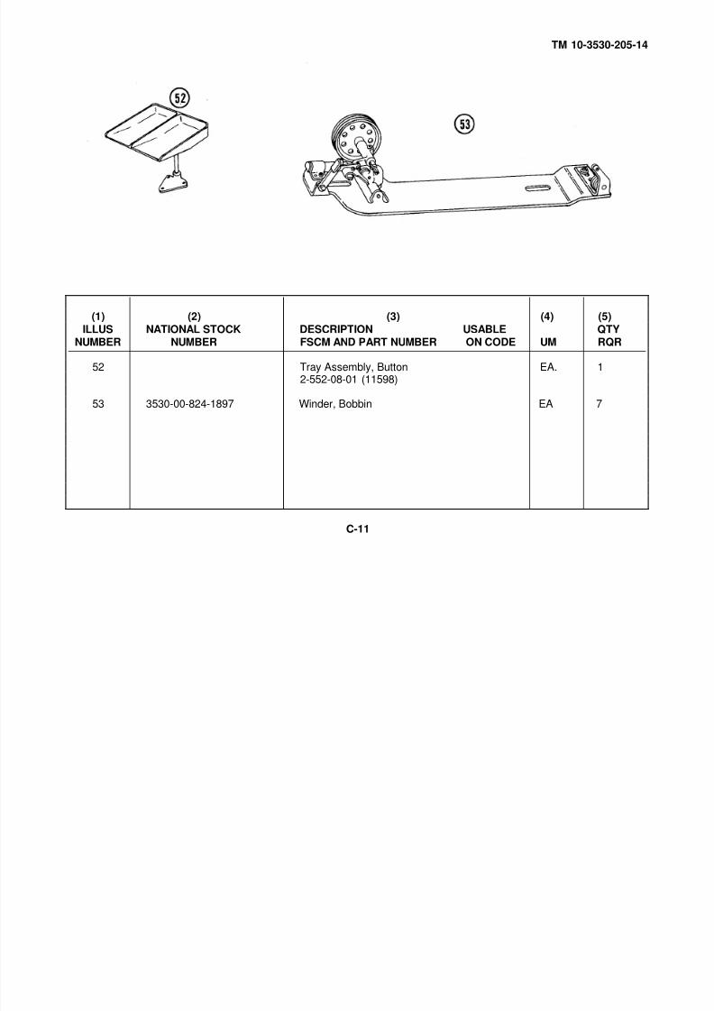
8/7/2019 TM 10-3530-205-10 CLOTHING REPAIR SHOP
http://slidepdf.com/reader/full/tm-10-3530-205-10-clothing-repair-shop 419/455
TM 10-3530-205-14
(1) (2) (3) (4) (5)ILLUS NATIONAL STOCK DESCRIPTION USABLE QTY
NUMBER NUMBER FSCM AND PART NUMBER ON CODE UM RQR
52 Tray Assembly, Button EA. 12-552-08-01 (11598)
53 3530-00-824-1897 Winder, Bobbin EA 7
C-11
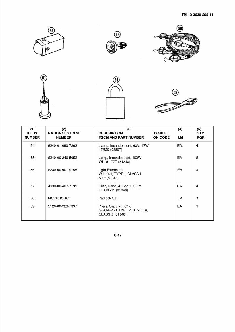
8/7/2019 TM 10-3530-205-10 CLOTHING REPAIR SHOP
http://slidepdf.com/reader/full/tm-10-3530-205-10-clothing-repair-shop 420/455
TM 10-3530-205-14
(1) (2) (3) (4) (5)ILLUS NATIONAL STOCK DESCRIPTION USABLE QTY
NUMBER NUMBER FSCM AND PART NUMBER ON CODE UM RQR
54 6240-01-090-7262 L amp, Incandescent, 63V, 17W EA. 417R20 (08807)
55 6240-00-246-5052 Lamp, Incandescent, 100W EA 8WL101-77T (81348)
56 6230-00-901-9755 Light Extension EA 4W-L-661, TYPE I, CLASS I50 ft (81348)
57 4930-00-407-7195 Oiler, Hand, 4" Spout 1/2 pt EA 4GGG0591 (81348)
58 MS21313-162 Padlock Set EA 1
59 5120-00-223-7397 Pliers, Slip Joint 8" lg EA 1GGG-P-471 TYPE 2, STYLE A,
CLASS 2 (81348)
C-12
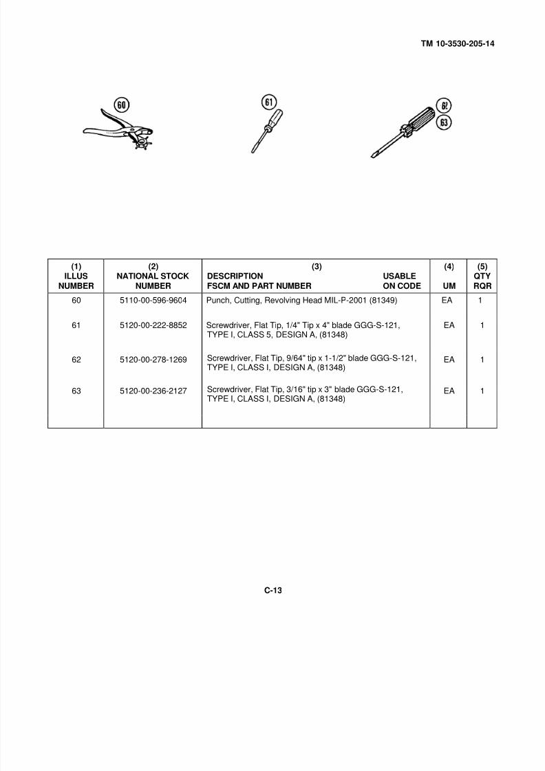
8/7/2019 TM 10-3530-205-10 CLOTHING REPAIR SHOP
http://slidepdf.com/reader/full/tm-10-3530-205-10-clothing-repair-shop 421/455
TM 10-3530-205-14
(1)ILLUS
NUMBER
(2)NATIONAL STOCK
NUMBER
(3)DESCRIPTION USABLEFSCM AND PART NUMBER ON CODE
(4)
UM
(5)QTYRQR
60 5110-00-596-9604 Punch, Cutting, Revolving Head MIL-P-2001 (81349) EA 1
61 5120-00-222-8852 Screwdriver, Flat Tip, 1/4" Tip x 4" blade GGG-S-121,TYPE I, CLASS 5, DESIGN A, (81348)
EA 1
62 5120-00-278-1269 Screwdriver, Flat Tip, 9/64" tip x 1-1/2" blade GGG-S-121,TYPE I, CLASS I, DESIGN A, (81348)
EA 1
63 5120-00-236-2127 Screwdriver, Flat Tip, 3/16" tip x 3" blade GGG-S-121,TYPE I, CLASS I, DESIGN A, (81348)
EA 1
C-13
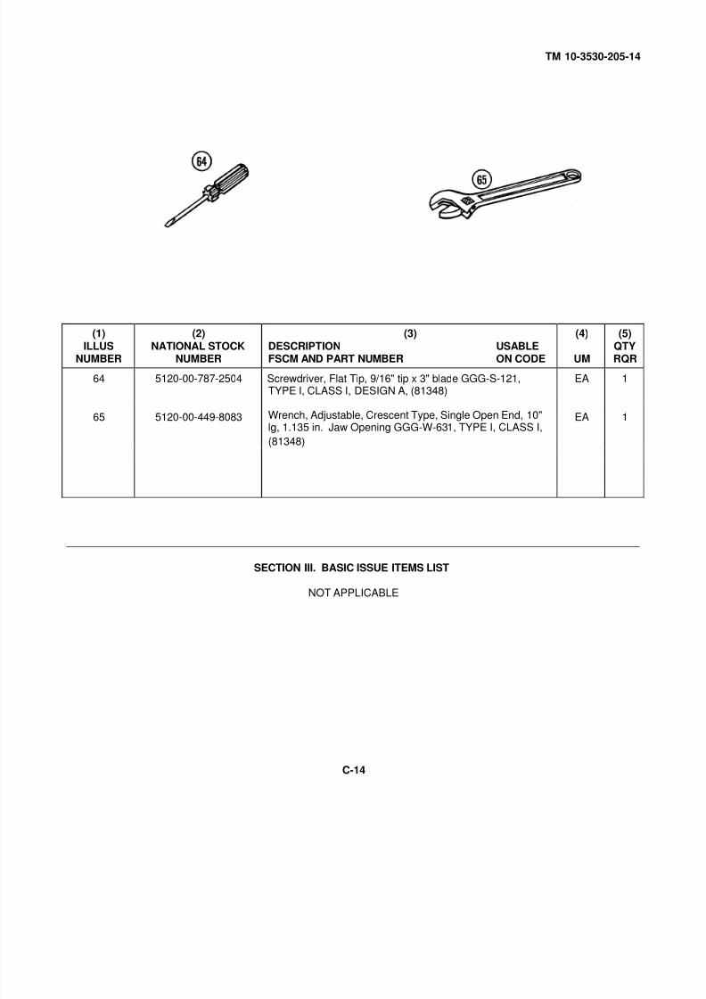
8/7/2019 TM 10-3530-205-10 CLOTHING REPAIR SHOP
http://slidepdf.com/reader/full/tm-10-3530-205-10-clothing-repair-shop 422/455
TM 10-3530-205-14
(1)ILLUS
NUMBER
(2)NATIONAL STOCK
NUMBER
(3)DESCRIPTION USABLEFSCM AND PART NUMBER ON CODE
(4)
UM
(5)QTYRQR
64 5120-00-787-2504 Screwdriver, Flat Tip, 9/16" tip x 3" blade GGG-S-121,TYPE I, CLASS I, DESIGN A, (81348)
EA 1
65 5120-00-449-8083 Wrench, Adjustable, Crescent Type, Single Open End, 10"lg, 1.135 in. Jaw Opening GGG-W-631, TYPE I, CLASS I,(81348)
EA 1
SECTION III. BASIC ISSUE ITEMS LIST
NOT APPLICABLE
C-14
8/7/2019 TM 10-3530-205-10 CLOTHING REPAIR SHOP
http://slidepdf.com/reader/full/tm-10-3530-205-10-clothing-repair-shop 423/455
TM 10-3530-205-14
APPENDIX D
ADDITIONAL AUTHORIZATION LIST
NOT APPLICABLE
D-1/D-2 Blank

8/7/2019 TM 10-3530-205-10 CLOTHING REPAIR SHOP
http://slidepdf.com/reader/full/tm-10-3530-205-10-clothing-repair-shop 424/455
8/7/2019 TM 10-3530-205-10 CLOTHING REPAIR SHOP
http://slidepdf.com/reader/full/tm-10-3530-205-10-clothing-repair-shop 425/455
TM 10-3530-205-14
APPENDIX E
EXPENDABLE/DURABLE SUPPLIES AND MATERIALS LIST
SECTION I. INTRODUCTION
E-1. SCOPE.
This listing is for informational purposes only and is not authority to requisition the listed items. These items areauthorized to you by CTA 50-970, Expendable/Durable Items (Except Medical, Class V, Repair Parts, and HeraldicItems), or CTA 8-100, Army Medical Department Expendable/Durable Items.
E-2. EXPLANATION OF COLUMNS.
a. Column 1 - Item Number. This number is assigned to the entry in the listing and is referenced in the narrativeinstructions to identify the material (e.g., "Use sealing compound, item 6, Appendix E” ).
b. Column 2 - Category. This column identifies the lowest category of maintenance that requires the listed item.
C - Operator/CrewO - Organizational MaintenanceF - Direct Support MaintenanceG - General Support Maintenance
c. Column 3 - National Stock Number. This is the national stock number assigned to the item; use it to request orrequisition the item.
d. Column 4 - Description. Indicates the federal item name and, if required, a description to identify the item. Thelast line for each item indicates the part number followed by the Federal Supply Code for Manufacturer (FSCM) inparentheses, if applicable.
e. Column 5 - Unit of Measure (U/M). Indicates the measure used in performing the actual maintenance function.This measure is expressed by a two-character alphabetical abbreviation (e.g., ea., in, pr). If the unit of measure differsfrom the unit of issue, requisition the lowest unit of issue that will satisfy your requirements.
E-1
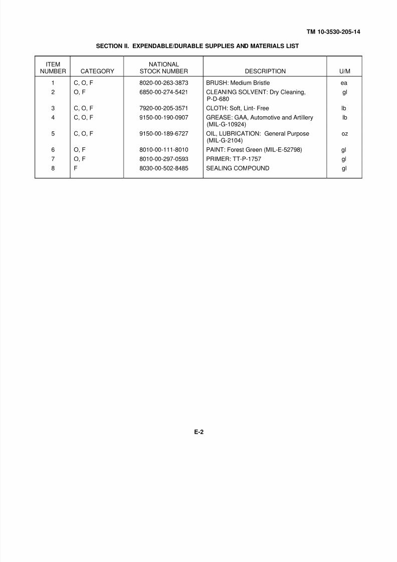
8/7/2019 TM 10-3530-205-10 CLOTHING REPAIR SHOP
http://slidepdf.com/reader/full/tm-10-3530-205-10-clothing-repair-shop 426/455
TM 10-3530-205-14
SECTION II. EXPENDABLE/DURABLE SUPPLIES AND MATERIALS LIST
ITEMNUMBER CATEGORY
NATIONALSTOCK NUMBER DESCRIPTION U/M
1 C, O, F 8020-00-263-3873 BRUSH: Medium Bristle ea
2 O, F 6850-00-274-5421 CLEANING SOLVENT: Dry Cleaning,P-D-680
gl
3 C, O, F 7920-00-205-3571 CLOTH: Soft, Lint- Free lb4 C, O, F 9150-00-190-0907 GREASE: GAA, Automotive and Artillery
(MIL-G-10924)lb
5 C, O, F 9150-00-189-6727 OIL, LUBRICATION: General Purpose(MIL-G-2104)
oz
6 O, F 8010-00-111-8010 PAINT: Forest Green (MIL-E-52798) gl7 O, F 8010-00-297-0593 PRIMER: TT-P-1757 gl8 F 8030-00-502-8485 SEALING COMPOUND gl
E-2
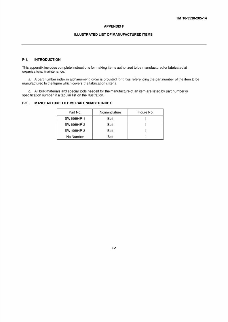
8/7/2019 TM 10-3530-205-10 CLOTHING REPAIR SHOP
http://slidepdf.com/reader/full/tm-10-3530-205-10-clothing-repair-shop 427/455
TM 10-3530-205-14
APPENDIX F
ILLUSTRATED LIST OF MANUFACTURED ITEMS
F-1. INTRODUCTION
This appendix includes complete instructions for making items authorized to be manufactured or fabricated atorganizational maintenance.
a . A part number index in alphanumeric order is provided for cross referencing the part number of the item to bemanufactured to the figure which covers the fabrication criteria.
b . All bulk materials and special tools needed for the manufacture of an item are listed by part number orspecification number in a tabular list on the illustration.
F-2. MANUFACTURED ITEMS PART NUMBER INDEX
Part No. Nomenclature Figure No.
SW19694P-1 Belt 1
SW19694P-2 Belt 1
SW19694P-3 Belt 1
No Number Belt 1
F-1
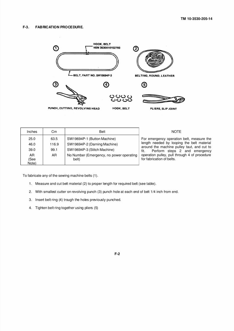
8/7/2019 TM 10-3530-205-10 CLOTHING REPAIR SHOP
http://slidepdf.com/reader/full/tm-10-3530-205-10-clothing-repair-shop 428/455
TM 10-3530-205-14
F-3. FABRICATION PROCEDURE.
Inches Cm Belt NOTE
25.046.039.0AR
(SeeNote)
63.5116.999.1AR
SW19694P-1 (Button Machine)SW19694P-2 (Darning Machine)SW19694P-3 (Stitch Machine)No Number (Emergency, no power operating
belt)
For emergency operation belt, measure thelength needed by looping the belt materialaround the machine pulley taut, and cut tofit. Perform steps 2 and emergencyoperation pulley, pull through 4 of procedure
for fabrication of belts.
To fabricate any of the sewing machine belts (1).
1. Measure and cut belt material (2) to proper length for required belt (see table).
2. With smallest cutter on revolving punch (3) punch hole at each end of belt 1/4 inch from end.
3. Insert belt ring (4) trough the holes previously punched.
4. Tighten belt ring together using pliers (5)
F-2
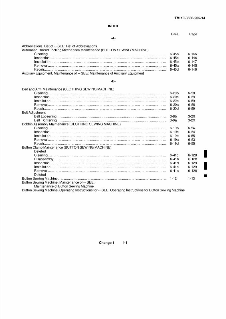
8/7/2019 TM 10-3530-205-10 CLOTHING REPAIR SHOP
http://slidepdf.com/reader/full/tm-10-3530-205-10-clothing-repair-shop 429/455
TM 10-3530-205-14
INDEX
Para. Page-A-
Abbreviations, List of -- SEE: List of Abbreviations
Automatic Thread Locking Mechanism Maintenance (BUTTON SEWING MACHINE)Cleaning................................ ................................ ................................ ........................... 6-45b 6-146Inspection................................ ................................ ................................ ......................... 6-45c 6-146Installation................................ ................................ ................................ ........................ 6-45e 6-147Removal ................................ ................................ ................................ ........................... 6-45a 6-145Repair................................ ................................ ................................ ............................... 6-45d 6-146
Auxiliary Equipment, Maintenance of -- SEE: Maintenance of Auxiliary Equipment
-B-
Bed and Arm Maintenance (CLOTHING SEWING MACHINE)Cleaning................................ ................................ ................................ ........................... 6-20b 6-58Inspection................................ ................................ ................................ ......................... 6-20c 6-59Installation................................ ................................ ................................ ........................ 6-20e 6-59Removal ................................ ................................ ................................ ........................... 6-20a 6-58Repair................................ ................................ ................................ ............................... 6-20d 6-59
Belt AdjustmentBelt Loosening................................ ................................ ................................ .................. 3-8b 3-29Belt Tightening ................................ ................................ ................................ ................. 3-8a 3-29
Bobbin Assembly Maintenance (CLOTHING SEWING MACHINE)Cleaning................................ ................................ ................................ ........................... 6-19b 6-54Inspection................................ ................................ ................................ ......................... 6-19c 6-54Installation................................ ................................ ................................ ........................ 6-19e 6-55Removal ................................ ................................ ................................ ........................... 6-19a 6-53Repair................................ ................................ ................................ ............................... 6-19d 6-55
Button Clamp Maintenance (BUTTON SEWING MACHINE)DeletedCleaning................................ ................................ ................................ ........................... 6-41c 6-128Disassembly................................ ................................ ................................ ..................... 6-41b 6-128Inspection................................ ................................ ................................ ......................... 6-41d 6-129Installation................................ ................................ ................................ ........................ 6-41e 6-129Removal ................................ ................................ ................................ ........................... 6-41a 6-128Deleted
Button Sewing Machine................................ ................................ ................................ ................. 1-12 1-13Button Sewing Machine, Maintenance of -- SEE:
Maintenance of Button Sewing MachineButton Sewing Machine, Operating Instructions for -- SEE: Operating Instructions for Button Sewing Machine
Change 1 I-1
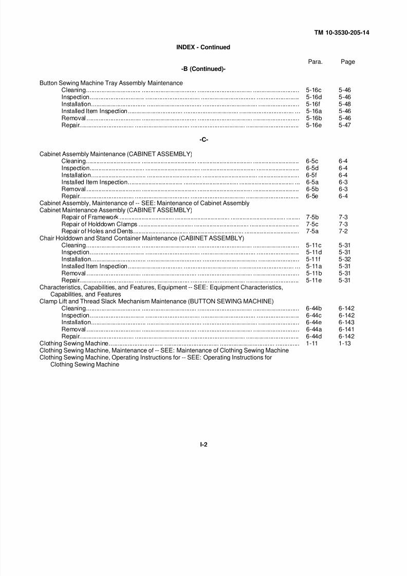
8/7/2019 TM 10-3530-205-10 CLOTHING REPAIR SHOP
http://slidepdf.com/reader/full/tm-10-3530-205-10-clothing-repair-shop 430/455
TM 10-3530-205-14
INDEX - Continued
Para. Page-B (Continued)-
Button Sewing Machine Tray Assembly Maintenance
Cleaning................................ ................................ ................................ ........................... 5-16c 5-46Inspection................................ ................................ ................................ ......................... 5-16d 5-46Installation................................ ................................ ................................ ........................ 5-16f 5-48Installed Item Inspection ................................ ................................ ................................ ... 5-16a 5-46Removal ................................ ................................ ................................ ........................... 5-16b 5-46Repair................................ ................................ ................................ ............................... 5-16e 5-47
-C-
Cabinet Assembly Maintenance (CABINET ASSEMBLY)Cleaning................................ ................................ ................................ ........................... 6-5c 6-4Inspection................................ ................................ ................................ ......................... 6-5d 6-4Installation................................ ................................ ................................ ........................ 6-5f 6-4Installed Item Inspection................................ ................................ ................................ ... 6-5a 6-3Removal ................................ ................................ ................................ ........................... 6-5b 6-3Repair................................ ................................ ................................ ............................... 6-5e 6-4
Cabinet Assembly, Maintenance of -- SEE: Maintenance of Cabinet AssemblyCabinet Maintenance Assembly (CABINET ASSEMBLY)
Repair of Framework ................................ ................................ ................................ ........ 7-5b 7-3Repair of Holddown Clamps ................................ ................................ ............................. 7-5c 7-3Repair of Holes and Dents................................ ................................ ................................ 7-5a 7-2
Chair Holddown and Stand Container Maintenance (CABINET ASSEMBLY)Cleaning................................ ................................ ................................ ........................... 5-11c 5-31Inspection................................ ................................ ................................ ......................... 5-11d 5-31Installation................................ ................................ ................................ ........................ 5-11f 5-32Installed Item Inspection ................................ ................................ ................................ ... 5-11a 5-31Removal ................................ ................................ ................................ ........................... 5-11b 5-31Repair................................ ................................ ................................ ............................... 5-11e 5-31
Characteristics, Capabilities, and Features, Equipment -- SEE: Equipment Characteristics,Capabilities, and Features
Clamp Lift and Thread Slack Mechanism Maintenance (BUTTON SEWING MACHINE)Cleaning................................ ................................ ................................ ........................... 6-44b 6-142Inspection................................ ................................ ................................ ......................... 6-44c 6-142Installation................................ ................................ ................................ ........................ 6-44e 6-143Removal ................................ ................................ ................................ ........................... 6-44a 6-141Repair................................ ................................ ................................ ............................... 6-44d 6-142
Clothing Sewing Machine................................ ................................ ................................ .............. 1-11 1-13Clothing Sewing Machine, Maintenance of -- SEE: Maintenance of Clothing Sewing MachineClothing Sewing Machine, Operating Instructions for -- SEE: Operating Instructions for
Clothing Sewing Machine
I-2
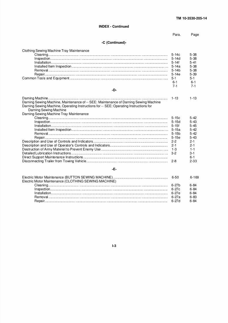
8/7/2019 TM 10-3530-205-10 CLOTHING REPAIR SHOP
http://slidepdf.com/reader/full/tm-10-3530-205-10-clothing-repair-shop 431/455
TM 10-3530-205-14
INDEX - Continued
Para. Page
-C (Continued)-
Clothing Sewing Machine Tray MaintenanceCleaning................................ ................................ ................................ ........................... 5-14c 5-38Inspection................................ ................................ ................................ ......................... 5-14d 5-38Installation................................ ................................ ................................ ........................ 5-14f 5-41Installed Item Inspection ................................ ................................ ................................ ... 5-14a 5-38Removal ................................ ................................ ................................ ........................... 5-14b 5-38Repair................................ ................................ ................................ ............................... 5-14e 5-39
Common Tools and Equipment ................................ ................................ ................................ ..... 5-1 5-16-1 6-17-1 7-1
-D-
Darning Machine................................ ................................ ................................ ........................... 1-13 1-13Darning Sewing Machine, Maintenance of -- SEE: Maintenance of Darning Sewing MachineDarning Sewing Machine, Operating Instructions for -- SEE: Operating Instructions for
Darning Sewing MachineDarning Sewing Machine Tray Maintenance
Cleaning................................ ................................ ................................ ........................... 5-15c 5-42Inspection................................ ................................ ................................ ......................... 5-15d 5-43Installation................................ ................................ ................................ ........................ 5-15f 5-45Installed Item Inspection ................................ ................................ ................................ ... 5-15a 5-42Removal ................................ ................................ ................................ ........................... 5-15b 5-42Repair................................ ................................ ................................ ............................... 5-15e 5-43
Description and Use of Controls and Indicators................................ ................................ ............. 2-2 2-1Description and Use of Operator's Controls and Indicators................................ ............................ 2-1 2-1Destruction of Army Materiel to Prevent Enemy Use ................................ ................................ ..... 1-3 1-1Detailed Lubrication Instructions ................................ ................................ ................................ ... 3-2 3-1Direct Support Maintenance Instructions ................................ ................................ ....................... 6-1Disconnecting Trailer from Towing Vehicle................................ ................................ .................... 2-8 2-33
-E-
Electric Motor Maintenance (BUTTON SEWING MACHINE)................................ ......................... 6-50 6-169Electric Motor Maintenance (CLOTHING SEWING MACHINE)
Cleaning................................ ................................ ................................ ........................... 6-27b 6-84Inspection................................ ................................ ................................ ......................... 6-27c 6-84Installation................................ ................................ ................................ ........................ 6-27e 6-84Removal ................................ ................................ ................................ ........................... 6-27a 6-83Repair................................ ................................ ................................ ............................... 6-27d 6-84
I-3
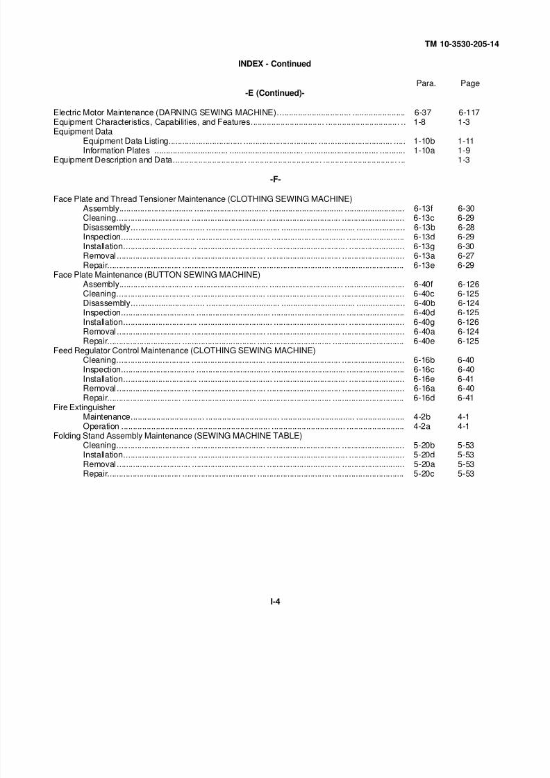
8/7/2019 TM 10-3530-205-10 CLOTHING REPAIR SHOP
http://slidepdf.com/reader/full/tm-10-3530-205-10-clothing-repair-shop 432/455
TM 10-3530-205-14
INDEX - Continued
Para. Page-E (Continued)-
Electric Motor Maintenance (DARNING SEWING MACHINE)................................ ....................... 6-37 6-117
Equipment Characteristics, Capabilities, and Features................................ ................................ .. 1-8 1-3Equipment DataEquipment Data Listing................................ ................................ ................................ ..... 1-10b 1-11Information Plates ................................ ................................ ................................ ........... 1-10a 1-9
Equipment Description and Data................................ ................................ ................................ ... 1-3
-F-
Face Plate and Thread Tensioner Maintenance (CLOTHING SEWING MACHINE)Assembly................................ ................................ ................................ .......................... 6-13f 6-30Cleaning................................ ................................ ................................ ........................... 6-13c 6-29Disassembly................................ ................................ ................................ ..................... 6-13b 6-28Inspection................................ ................................ ................................ ......................... 6-13d 6-29Installation................................ ................................ ................................ ........................ 6-13g 6-30Removal ................................ ................................ ................................ ........................... 6-13a 6-27Repair................................ ................................ ................................ ............................... 6-13e 6-29
Face Plate Maintenance (BUTTON SEWING MACHINE)Assembly................................ ................................ ................................ .......................... 6-40f 6-126Cleaning................................ ................................ ................................ ........................... 6-40c 6-125Disassembly................................ ................................ ................................ ..................... 6-40b 6-124Inspection................................ ................................ ................................ ......................... 6-40d 6-125Installation................................ ................................ ................................ ........................ 6-40g 6-126Removal ................................ ................................ ................................ ........................... 6-40a 6-124Repair................................ ................................ ................................ ............................... 6-40e 6-125
Feed Regulator Control Maintenance (CLOTHING SEWING MACHINE)Cleaning................................ ................................ ................................ ........................... 6-16b 6-40Inspection................................ ................................ ................................ ......................... 6-16c 6-40Installation................................ ................................ ................................ ........................ 6-16e 6-41Removal ................................ ................................ ................................ ........................... 6-16a 6-40Repair................................ ................................ ................................ ............................... 6-16d 6-41
Fire ExtinguisherMaintenance................................ ................................ ................................ ..................... 4-2b 4-1Operation ................................ ................................ ................................ ......................... 4-2a 4-1
Folding Stand Assembly Maintenance (SEWING MACHINE TABLE)Cleaning................................ ................................ ................................ ........................... 5-20b 5-53Installation................................ ................................ ................................ ........................ 5-20d 5-53Removal ................................ ................................ ................................ ........................... 5-20a 5-53Repair................................ ................................ ................................ ............................... 5-20c 5-53
I-4
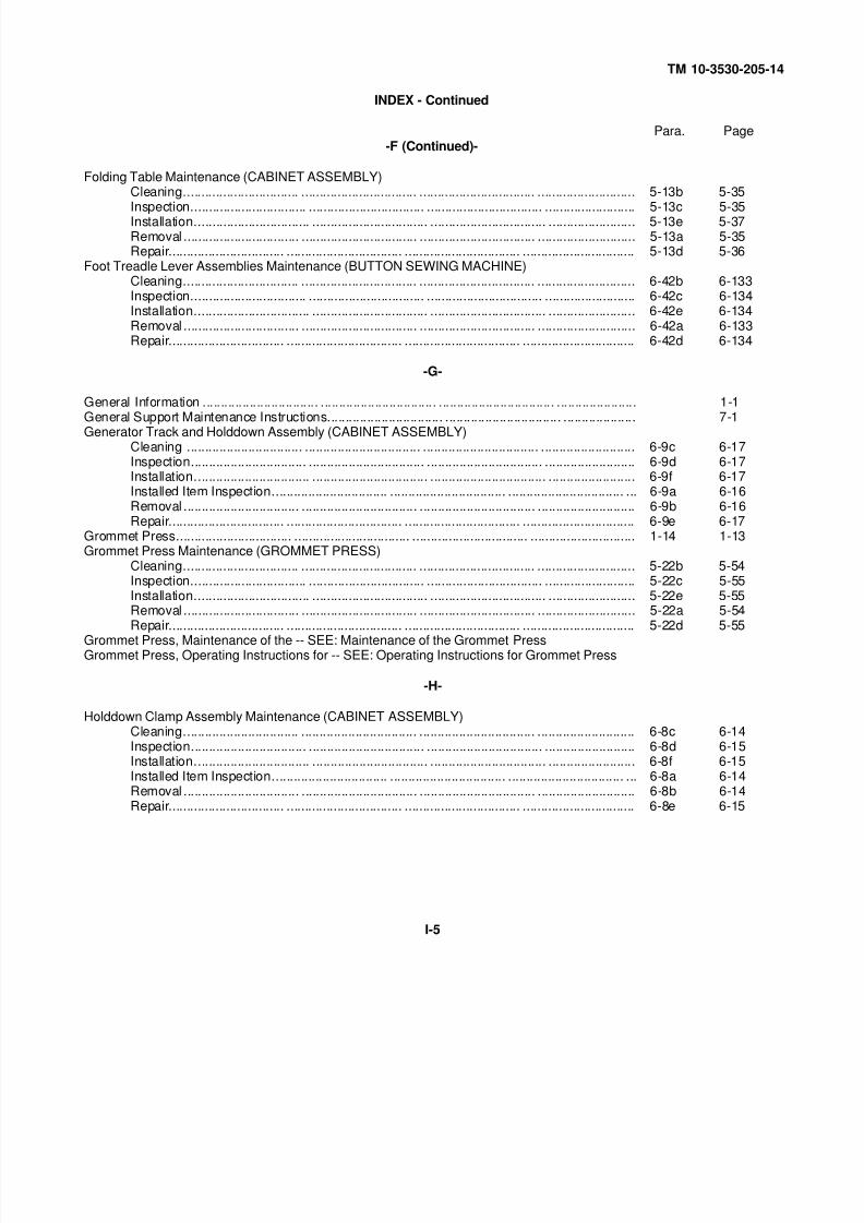
8/7/2019 TM 10-3530-205-10 CLOTHING REPAIR SHOP
http://slidepdf.com/reader/full/tm-10-3530-205-10-clothing-repair-shop 433/455
TM 10-3530-205-14
INDEX - Continued
Para. Page-F (Continued)-
Folding Table Maintenance (CABINET ASSEMBLY)
Cleaning................................ ................................ ................................ ........................... 5-13b 5-35Inspection................................ ................................ ................................ ......................... 5-13c 5-35Installation................................ ................................ ................................ ........................ 5-13e 5-37Removal ................................ ................................ ................................ ........................... 5-13a 5-35Repair................................ ................................ ................................ ............................... 5-13d 5-36
Foot Treadle Lever Assemblies Maintenance (BUTTON SEWING MACHINE)Cleaning................................ ................................ ................................ ........................... 6-42b 6-133Inspection................................ ................................ ................................ ......................... 6-42c 6-134Installation................................ ................................ ................................ ........................ 6-42e 6-134Removal ................................ ................................ ................................ ........................... 6-42a 6-133Repair................................ ................................ ................................ ............................... 6-42d 6-134
-G-
General Information ................................ ................................ ................................ ...................... 1-1General Support Maintenance Instructions................................ ................................ .................... 7-1Generator Track and Holddown Assembly (CABINET ASSEMBLY)
Cleaning ................................ ................................ ................................ .......................... 6-9c 6-17Inspection................................ ................................ ................................ ......................... 6-9d 6-17Installation................................ ................................ ................................ ........................ 6-9f 6-17Installed Item Inspection................................ ................................ ................................ ... 6-9a 6-16Removal ................................ ................................ ................................ ........................... 6-9b 6-16Repair................................ ................................ ................................ ............................... 6-9e 6-17
Grommet Press................................ ................................ ................................ ............................. 1-14 1-13Grommet Press Maintenance (GROMMET PRESS)
Cleaning................................ ................................ ................................ ........................... 5-22b 5-54Inspection................................ ................................ ................................ ......................... 5-22c 5-55Installation................................ ................................ ................................ ........................ 5-22e 5-55Removal ................................ ................................ ................................ ........................... 5-22a 5-54Repair................................ ................................ ................................ ............................... 5-22d 5-55
Grommet Press, Maintenance of the -- SEE: Maintenance of the Grommet PressGrommet Press, Operating Instructions for -- SEE: Operating Instructions for Grommet Press
-H-
Holddown Clamp Assembly Maintenance (CABINET ASSEMBLY)Cleaning................................ ................................ ................................ ........................... 6-8c 6-14Inspection................................ ................................ ................................ ......................... 6-8d 6-15Installation................................ ................................ ................................ ........................ 6-8f 6-15Installed Item Inspection................................ ................................ ................................ ... 6-8a 6-14Removal ................................ ................................ ................................ ........................... 6-8b 6-14Repair................................ ................................ ................................ ............................... 6-8e 6-15
I-5
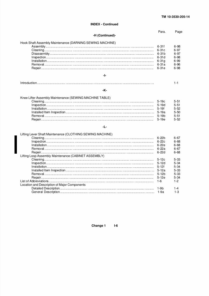
8/7/2019 TM 10-3530-205-10 CLOTHING REPAIR SHOP
http://slidepdf.com/reader/full/tm-10-3530-205-10-clothing-repair-shop 434/455
TM 10-3530-205-14
INDEX - Continued
Para. Page-H (Continued)-
Hook Shaft Assembly Maintenance (DARNING SEWING MACHINE)
Assembly................................ ................................ ................................ .......................... 6-31f 6-98Cleaning................................ ................................ ................................ ........................... 6-31c 6-97Disassembly................................ ................................ ................................ ..................... 6-31b 6-97Inspection................................ ................................ ................................ ......................... 6-31d 6-98Installation................................ ................................ ................................ ........................ 6-31g 6-99Removal ................................ ................................ ................................ ........................... 6-31a 6-96Repair................................ ................................ ................................ ............................... 6-31e 6-98
-I-
Introduction................................ ................................ ................................ ................................ ... 1-1
-K-
Knee Lifter Assembly Maintenance (SEWING MACHINE TABLE)Cleaning................................ ................................ ................................ ........................... 5-19c 5-51Inspection................................ ................................ ................................ ......................... 5-19d 5-51Installation................................ ................................ ................................ ........................ 5-19f 5-52Installed Item Inspection ................................ ................................ ................................ ... 5-19a 5-50Removal ................................ ................................ ................................ ........................... 5-19b 5-51Repair................................ ................................ ................................ ............................... 5-19e 5-52
-L-
Lifting Lever Shaft Maintenance (CLOTHING SEWING MACHINE)Cleaning................................ ................................ ................................ ........................... 6-22b 6-67Inspection................................ ................................ ................................ ......................... 6-22c 6-68Installation................................ ................................ ................................ ........................ 6-22e 6-68Removal ................................ ................................ ................................ ........................... 6-22a 6-67Repair................................ ................................ ................................ ............................... 6-22d 6-68
Lifting Loop Assembly Maintenance (CABINET ASSEMBLY)Cleaning................................ ................................ ................................ ........................... 5-12c 5-33Inspection................................ ................................ ................................ ......................... 5-12d 5-34Installation................................ ................................ ................................ ........................ 5-12f 5-34Installed Item Inspection ................................ ................................ ................................ ... 5-12a 5-33Removal ................................ ................................ ................................ ........................... 5-12b 5-33Repair................................ ................................ ................................ ............................... 5-12e 5-34
List of Abbreviations................................ ................................ ................................ ...................... 1-6 1-2Location and Description of Major Components
Detailed Description................................ ................................ ................................ .......... 1-9b 1-4General Description................................ ................................ ................................ .......... 1-9a 1-3
Change 1 I-6
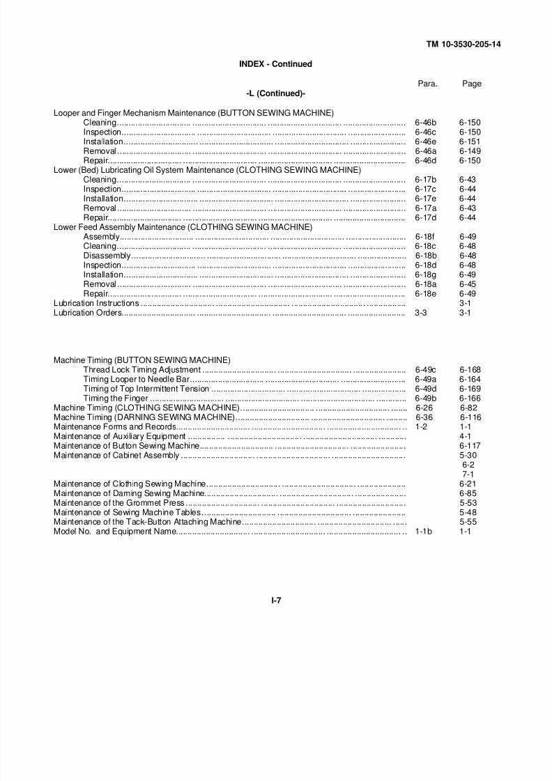
8/7/2019 TM 10-3530-205-10 CLOTHING REPAIR SHOP
http://slidepdf.com/reader/full/tm-10-3530-205-10-clothing-repair-shop 435/455
TM 10-3530-205-14
INDEX - Continued
Para. Page-L (Continued)-
Looper and Finger Mechanism Maintenance (BUTTON SEWING MACHINE)
Cleaning................................ ................................ ................................ ........................... 6-46b 6-150Inspection................................ ................................ ................................ ......................... 6-46c 6-150Installation................................ ................................ ................................ ........................ 6-46e 6-151Removal ................................ ................................ ................................ ........................... 6-46a 6-149Repair................................ ................................ ................................ ............................... 6-46d 6-150
Lower (Bed) Lubricating Oil System Maintenance (CLOTHING SEWING MACHINE)Cleaning................................ ................................ ................................ ........................... 6-17b 6-43Inspection................................ ................................ ................................ ......................... 6-17c 6-44Installation................................ ................................ ................................ ........................ 6-17e 6-44Removal ................................ ................................ ................................ ........................... 6-17a 6-43Repair................................ ................................ ................................ ............................... 6-17d 6-44
Lower Feed Assembly Maintenance (CLOTHING SEWING MACHINE)Assembly................................ ................................ ................................ .......................... 6-18f 6-49Cleaning................................ ................................ ................................ ........................... 6-18c 6-48Disassembly................................ ................................ ................................ ..................... 6-18b 6-48Inspection................................ ................................ ................................ ......................... 6-18d 6-48Installation................................ ................................ ................................ ........................ 6-18g 6-49Removal ................................ ................................ ................................ ........................... 6-18a 6-45Repair................................ ................................ ................................ ............................... 6-18e 6-49
Lubrication Instructions ................................ ................................ ................................ ................. 3-1Lubrication Orders................................ ................................ ................................ ......................... 3-3 3-1
Machine Timing (BUTTON SEWING MACHINE)Thread Lock Timing Adjustment ................................ ................................ ....................... 6-49c 6-168Timing Looper to Needle Bar................................ ................................ ............................ 6-49a 6-164Timing of Top Intermittent Tension ................................ ................................ ................... 6-49d 6-169Timing the Finger ................................ ................................ ................................ ............. 6-49b 6-166
Machine Timing (CLOTHING SEWING MACHINE)................................ ................................ ....... 6-26 6-82Machine Timing (DARNING SEWING MACHINE)................................ ................................ ......... 6-36 6-116Maintenance Forms and Records................................ ................................ ................................ .. 1-2 1-1Maintenance of Auxiliary Equipment ................ ................................ ................................ ............ 4-1Maintenance of Button Sewing Machine................................ ................................ ........................ 6-117Maintenance of Cabinet Assembly ................................ ................................ ................................ 5-30
6-27-1
Maintenance of Clothing Sewing Machine................................ ................................ ..................... 6-21Maintenance of Darning Sewing Machine................................ ................................ ...................... 6-85
Maintenance of the Grommet Press ................................ ................................ .............................. 5-53Maintenance of Sewing Machine Tables................................ ................................ ....................... 5-48Maintenance of the Tack-Button Attaching Machine................................ ................................ ...... 5-55Model No. and Equipment Name................................ ................................ ................................ .. 1-1b 1-1
I-7
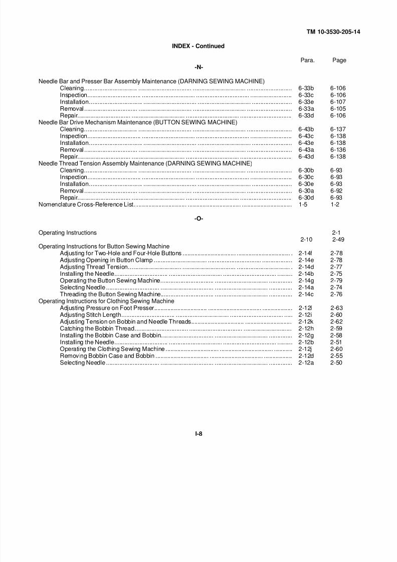
8/7/2019 TM 10-3530-205-10 CLOTHING REPAIR SHOP
http://slidepdf.com/reader/full/tm-10-3530-205-10-clothing-repair-shop 436/455
TM 10-3530-205-14
INDEX - Continued
Para. Page-N-
Needle Bar and Presser Bar Assembly Maintenance (DARNING SEWING MACHINE)
Cleaning................................ ................................ ................................ ........................... 6-33b 6-106Inspection................................ ................................ ................................ ......................... 6-33c 6-106Installation................................ ................................ ................................ ........................ 6-33e 6-107Removal ................................ ................................ ................................ ........................... 6-33a 6-105Repair................................ ................................ ................................ ............................... 6-33d 6-106
Needle Bar Drive Mechanism Maintenance (BUTTON SEWING MACHINE)Cleaning................................ ................................ ................................ ........................... 6-43b 6-137Inspection................................ ................................ ................................ ......................... 6-43c 6-138Installation................................ ................................ ................................ ........................ 6-43e 6-138Removal ................................ ................................ ................................ ........................... 6-43a 6-136Repair................................ ................................ ................................ ............................... 6-43d 6-138
Needle Thread Tension Assembly Maintenance (DARNING SEWING MACHINE)Cleaning................................ ................................ ................................ ........................... 6-30b 6-93Inspection................................ ................................ ................................ ......................... 6-30c 6-93Installation................................ ................................ ................................ ........................ 6-30e 6-93Removal ................................ ................................ ................................ ........................... 6-30a 6-92Repair................................ ................................ ................................ ............................... 6-30d 6-93
Nomenclature Cross-Reference List................................ ................................ .............................. 1-5 1-2
-O-
Operating Instructions 2-12-10 2-49
Operating Instructions for Button Sewing MachineAdjusting for Two-Hole and Four-Hole Buttons ................................ ................................ . 2-14f 2-78Adjusting Opening in Button Clamp ................................ ................................ .................. 2-14e 2-78Adjusting Thread Tension................................ ................................ ................................ . 2-14d 2-77Installing the Needle................................ ................................ ................................ ......... 2-14b 2-75Operating the Button Sewing Machine................................ ................................ .............. 2-14g 2-79Selecting Needle ................................ ................................ ................................ .............. 2-14a 2-74Threading the Button Sewing Machine................................ ................................ .............. 2-14c 2-76
Operating Instructions for Clothing Sewing MachineAdjusting Pressure on Foot Presser................................ ................................ .................. 2-12l 2-63Adjusting Stitch Length................................ ................................ ................................ ..... 2-12i 2-60Adjusting Tension on Bobbin and Needle Threads................................ ............................ 2-12k 2-62Catching the Bobbin Thread................................ ................................ ............................. 2-12h 2-59Installing the Bobbin Case and Bobbin................................ ................................ .............. 2-12g 2-58Installing the Needle................................ ................................ ................................ ......... 2-12b 2-51Operating the Clothing Sewing Machine ................................ ................................ ........... 2-12j 2-60Removing Bobbin Case and Bobbin ................................ ................................ ................. 2-12d 2-55
Selecting Needle ................................ ................................ ................................ .............. 2-12a 2-50
I-8
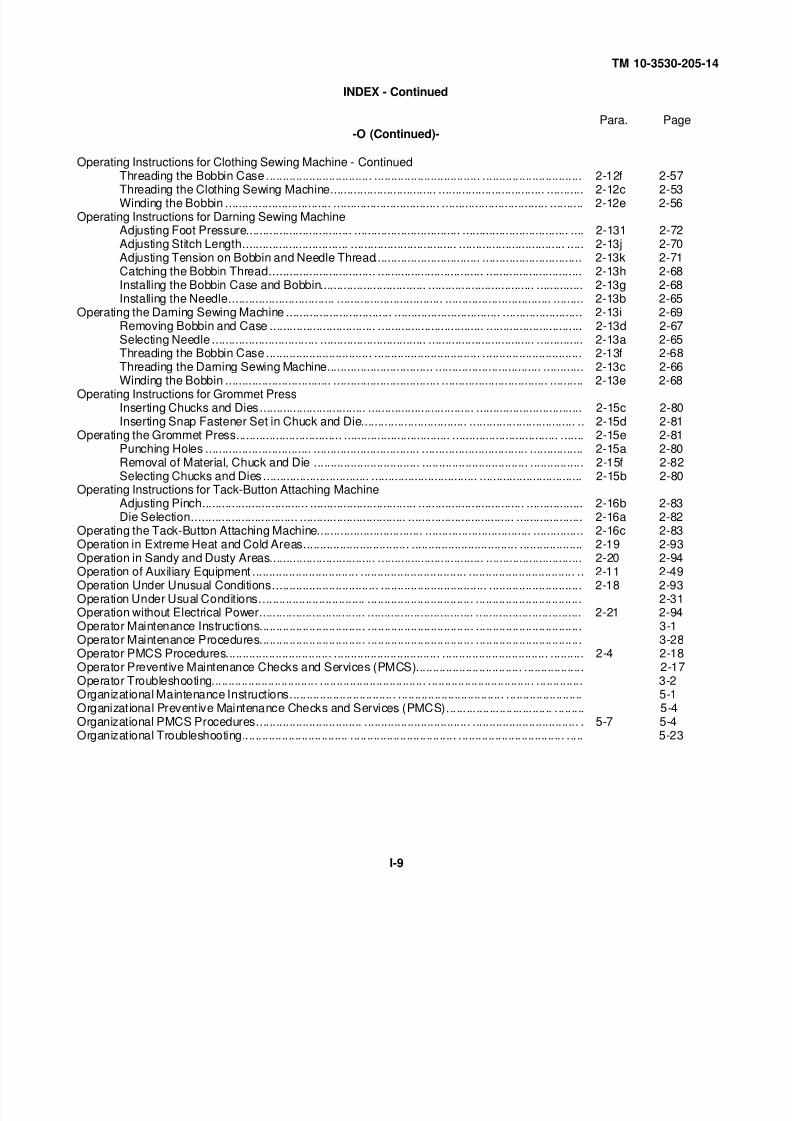
8/7/2019 TM 10-3530-205-10 CLOTHING REPAIR SHOP
http://slidepdf.com/reader/full/tm-10-3530-205-10-clothing-repair-shop 437/455
TM 10-3530-205-14
INDEX - Continued
Para. Page-O (Continued)-
Operating Instructions for Clothing Sewing Machine - Continued
Threading the Bobbin Case ................................ ................................ .............................. 2-12f 2-57Threading the Clothing Sewing Machine................................ ................................ ........... 2-12c 2-53Winding the Bobbin ................................ ................................ ................................ .......... 2-12e 2-56
Operating Instructions for Darning Sewing MachineAdjusting Foot Pressure................................ ................................ ................................ .... 2-131 2-72Adjusting Stitch Length................................ ................................ ................................ ..... 2-13j 2-70Adjusting Tension on Bobbin and Needle Thread................................ .............................. 2-13k 2-71Catching the Bobbin Thread................................ ................................ ............................. 2-13h 2-68Installing the Bobbin Case and Bobbin................................ ................................ .............. 2-13g 2-68Installing the Needle................................ ................................ ................................ ......... 2-13b 2-65
Operating the Darning Sewing Machine ................................ ................................ ........................ 2-13i 2-69Removing Bobbin and Case ................................ ................................ ............................. 2-13d 2-67Selecting Needle ................................ ................................ ................................ .............. 2-13a 2-65Threading the Bobbin Case ................................ ................................ .............................. 2-13f 2-68Threading the Darning Sewing Machine................................ ................................ ............ 2-13c 2-66Winding the Bobbin ................................ ................................ ................................ .......... 2-13e 2-68
Operating Instructions for Grommet PressInserting Chucks and Dies ................................ ................................ ................................ 2-15c 2-80Inserting Snap Fastener Set in Chuck and Die................................ ................................ .. 2-15d 2-81
Operating the Grommet Press................................ ................................ ................................ ....... 2-15e 2-81Punching Holes ................................ ................................ ................................ ................ 2-15a 2-80Removal of Material, Chuck and Die ................................ ................................ ................ 2-15f 2-82Selecting Chucks and Dies ................................ ................................ ............................... 2-15b 2-80
Operating Instructions for Tack-Button Attaching MachineAdjusting Pinch................................ ................................ ................................ ................. 2-16b 2-83Die Selection................................ ................................ ................................ .................... 2-16a 2-82
Operating the Tack-Button Attaching Machine................................ ................................ ............... 2-16c 2-83Operation in Extreme Heat and Cold Areas................................ ................................ ................... 2-19 2-93Operation in Sandy and Dusty Areas................................ ................................ ............................. 2-20 2-94Operation of Auxiliary Equipment ................................ ................................ ................................ .. 2-11 2-49Operation Under Unusual Conditions................................ ................................ ............................ 2-18 2-93Operation Under Usual Conditions................................ ................................ ................................ 2-31Operation without Electrical Power................................ ................................ ................................ 2-21 2-94Operator Maintenance Instructions................................ ................................ ................................ 3-1Operator Maintenance Procedures................................ ................................ ................................ 3-28Operator PMCS Procedures................................ ................................ ................................ .......... 2-4 2-18Operator Preventive Maintenance Checks and Services (PMCS)................................ .................. 2-17Operator Troubleshooting................................ ................................ ................................ .............. 3-2Organizational Maintenance Instructions................................ ................................ ....................... 5-1Organizational Preventive Maintenance Checks and Services (PMCS)................................ ......... 5-4
Organizational PMCS Procedures................................ ................................ ................................ . 5-7 5-4Organizational Troubleshooting................................ ................................ ................................ ..... 5-23
I-9
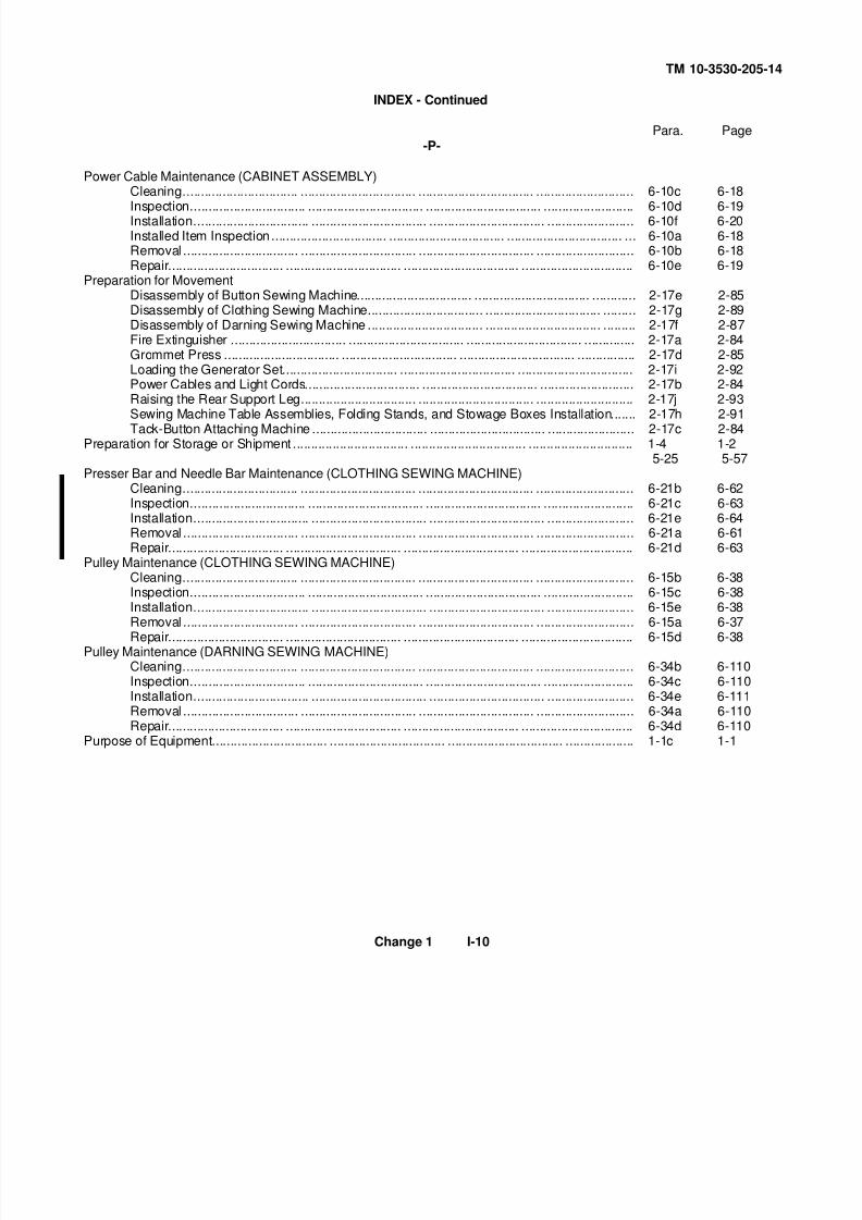
8/7/2019 TM 10-3530-205-10 CLOTHING REPAIR SHOP
http://slidepdf.com/reader/full/tm-10-3530-205-10-clothing-repair-shop 438/455
TM 10-3530-205-14
INDEX - Continued
Para. Page-P-
Power Cable Maintenance (CABINET ASSEMBLY)
Cleaning................................ ................................ ................................ ........................... 6-10c 6-18Inspection................................ ................................ ................................ ......................... 6-10d 6-19Installation................................ ................................ ................................ ........................ 6-10f 6-20Installed Item Inspection ................................ ................................ ................................ ... 6-10a 6-18Removal ................................ ................................ ................................ ........................... 6-10b 6-18Repair................................ ................................ ................................ ............................... 6-10e 6-19
Preparation for MovementDisassembly of Button Sewing Machine................................ ................................ ............ 2-17e 2-85Disassembly of Clothing Sewing Machine................................ ................................ ......... 2-17g 2-89Disassembly of Darning Sewing Machine ................................ ................................ ......... 2-17f 2-87Fire Extinguisher ................................ ................................ ................................ .............. 2-17a 2-84Grommet Press ................................ ................................ ................................ ................ 2-17d 2-85Loading the Generator Set................................ ................................ ................................ 2-17i 2-92Power Cables and Light Cords................................ ................................ .......................... 2-17b 2-84Raising the Rear Support Leg................................ ................................ ........................... 2-17j 2-93Sewing Machine Table Assemblies, Folding Stands, and Stowage Boxes Installation....... 2-17h 2-91Tack-Button Attaching Machine ................................ ................................ ........................ 2-17c 2-84
Preparation for Storage or Shipment ................................ ................................ ............................. 1-4 1-25-25 5-57
Presser Bar and Needle Bar Maintenance (CLOTHING SEWING MACHINE)Cleaning................................ ................................ ................................ ........................... 6-21b 6-62Inspection................................ ................................ ................................ ......................... 6-21c 6-63Installation................................ ................................ ................................ ........................ 6-21e 6-64Removal ................................ ................................ ................................ ........................... 6-21a 6-61Repair................................ ................................ ................................ ............................... 6-21d 6-63
Pulley Maintenance (CLOTHING SEWING MACHINE)Cleaning................................ ................................ ................................ ........................... 6-15b 6-38Inspection................................ ................................ ................................ ......................... 6-15c 6-38Installation................................ ................................ ................................ ........................ 6-15e 6-38Removal ................................ ................................ ................................ ........................... 6-15a 6-37Repair................................ ................................ ................................ ............................... 6-15d 6-38
Pulley Maintenance (DARNING SEWING MACHINE)Cleaning................................ ................................ ................................ ........................... 6-34b 6-110Inspection................................ ................................ ................................ ......................... 6-34c 6-110Installation................................ ................................ ................................ ........................ 6-34e 6-111Removal ................................ ................................ ................................ ........................... 6-34a 6-110Repair................................ ................................ ................................ ............................... 6-34d 6-110
Purpose of Equipment................................ ................................ ................................ ................... 1-1c 1-1
Change 1 I-10
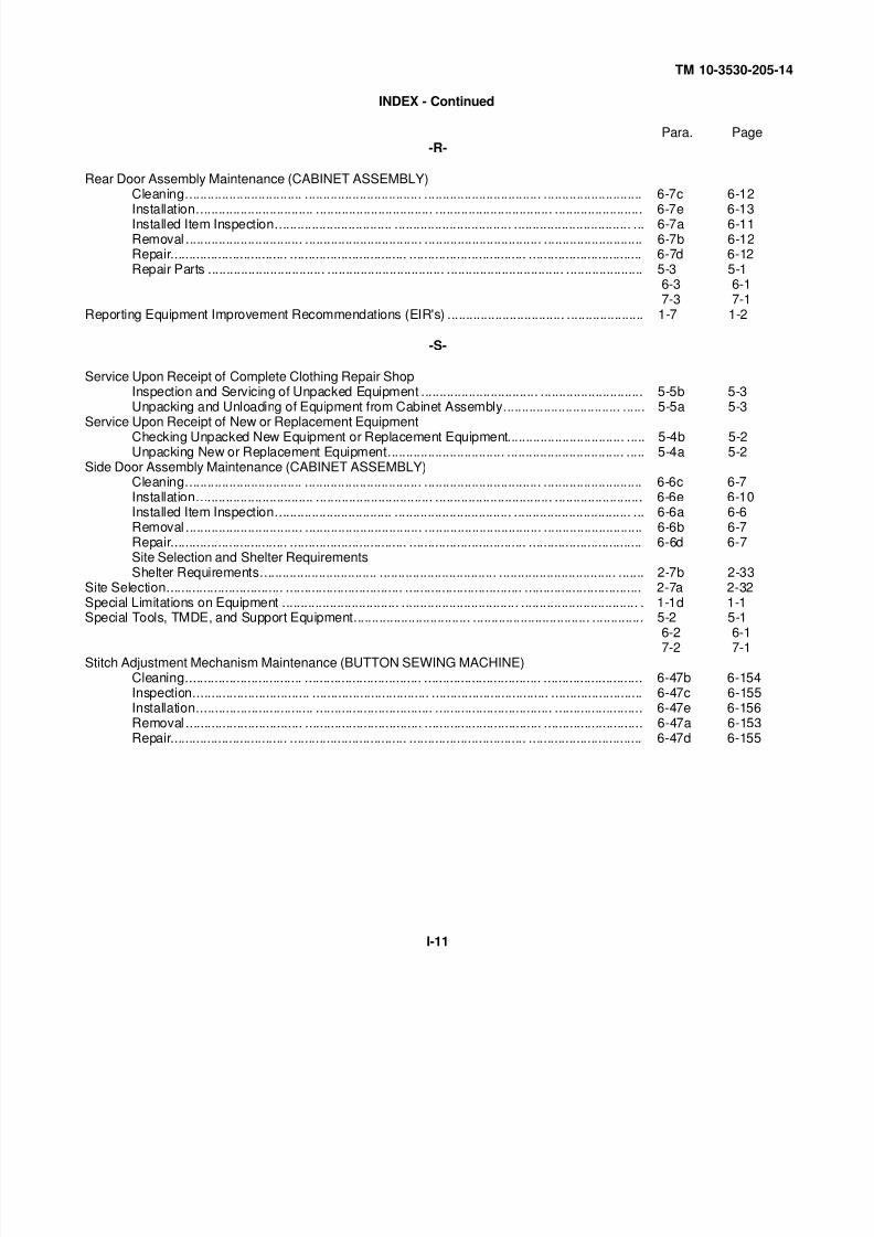
8/7/2019 TM 10-3530-205-10 CLOTHING REPAIR SHOP
http://slidepdf.com/reader/full/tm-10-3530-205-10-clothing-repair-shop 439/455
TM 10-3530-205-14
INDEX - Continued
Para. Page-R-
Rear Door Assembly Maintenance (CABINET ASSEMBLY)
Cleaning................................ ................................ ................................ ........................... 6-7c 6-12Installation................................ ................................ ................................ ........................ 6-7e 6-13Installed Item Inspection................................ ................................ ................................ ... 6-7a 6-11Removal ................................ ................................ ................................ ........................... 6-7b 6-12Repair................................ ................................ ................................ ............................... 6-7d 6-12Repair Parts ................................ ................................ ................................ ..................... 5-3 5-1
6-3 6-17-3 7-1
Reporting Equipment Improvement Recommendations (EIR's) ................................ ..................... 1-7 1-2
-S-
Service Upon Receipt of Complete Clothing Repair ShopInspection and Servicing of Unpacked Equipment ................................ ............................ 5-5b 5-3Unpacking and Unloading of Equipment from Cabinet Assembly................................ ...... 5-5a 5-3
Service Upon Receipt of New or Replacement EquipmentChecking Unpacked New Equipment or Replacement Equipment................................ ..... 5-4b 5-2Unpacking New or Replacement Equipment................................ ................................ ..... 5-4a 5-2
Side Door Assembly Maintenance (CABINET ASSEMBLY)Cleaning................................ ................................ ................................ ........................... 6-6c 6-7Installation................................ ................................ ................................ ........................ 6-6e 6-10Installed Item Inspection................................ ................................ ................................ ... 6-6a 6-6Removal ................................ ................................ ................................ ........................... 6-6b 6-7Repair................................ ................................ ................................ ............................... 6-6d 6-7Site Selection and Shelter RequirementsShelter Requirements................................ ................................ ................................ ....... 2-7b 2-33
Site Selection................................ ................................ ................................ ................................ 2-7a 2-32Special Limitations on Equipment ................................ ................................ ................................ . 1-1d 1-1Special Tools, TMDE, and Support Equipment................................ ................................ .............. 5-2 5-1
6-2 6-17-2 7-1
Stitch Adjustment Mechanism Maintenance (BUTTON SEWING MACHINE)Cleaning................................ ................................ ................................ ........................... 6-47b 6-154Inspection................................ ................................ ................................ ......................... 6-47c 6-155Installation................................ ................................ ................................ ........................ 6-47e 6-156Removal ................................ ................................ ................................ ........................... 6-47a 6-153Repair................................ ................................ ................................ ............................... 6-47d 6-155
I-11
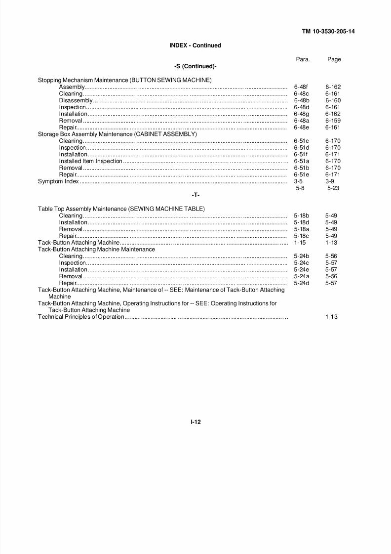
8/7/2019 TM 10-3530-205-10 CLOTHING REPAIR SHOP
http://slidepdf.com/reader/full/tm-10-3530-205-10-clothing-repair-shop 440/455
TM 10-3530-205-14
INDEX - Continued
Para. Page-S (Continued)-
Stopping Mechanism Maintenance (BUTTON SEWING MACHINE)
Assembly................................ ................................ ................................ .......................... 6-48f 6-162Cleaning................................ ................................ ................................ ........................... 6-48c 6-161Disassembly................................ ................................ ................................ ..................... 6-48b 6-160Inspection................................ ................................ ................................ ......................... 6-48d 6-161Installation................................ ................................ ................................ ........................ 6-48g 6-162Removal ................................ ................................ ................................ ........................... 6-48a 6-159Repair................................ ................................ ................................ ............................... 6-48e 6-161
Storage Box Assembly Maintenance (CABINET ASSEMBLY)Cleaning................................ ................................ ................................ ........................... 6-51c 6-170Inspection................................ ................................ ................................ ......................... 6-51d 6-170Installation................................ ................................ ................................ ........................ 6-51f 6-171Installed Item Inspection ................................ ................................ ................................ ... 6-51a 6-170Removal ................................ ................................ ................................ ........................... 6-51b 6-170Repair................................ ................................ ................................ ............................... 6-51e 6-171
Symptom Index ................................ ................................ ................................ ............................. 3-5 3-95-8 5-23
-T-
Table Top Assembly Maintenance (SEWING MACHINE TABLE)Cleaning................................ ................................ ................................ ........................... 5-18b 5-49Installation................................ ................................ ................................ ........................ 5-18d 5-49Removal ................................ ................................ ................................ ........................... 5-18a 5-49Repair................................ ................................ ................................ ............................... 5-18c 5-49
Tack-Button Attaching Machine................................ ................................ ................................ ..... 1-15 1-13Tack-Button Attaching Machine Maintenance
Cleaning................................ ................................ ................................ ........................... 5-24b 5-56Inspection................................ ................................ ................................ ......................... 5-24c 5-57Installation................................ ................................ ................................ ........................ 5-24e 5-57Removal ................................ ................................ ................................ ........................... 5-24a 5-56Repair................................ ................................ ................................ ............................... 5-24d 5-57
Tack-Button Attaching Machine, Maintenance of -- SEE: Maintenance of Tack-Button AttachingMachine
Tack-Button Attaching Machine, Operating Instructions for -- SEE: Operating Instructions forTack-Button Attaching Machine
Technical Principles of Operation................................ ................................ ................................ .. 1-13
I-12
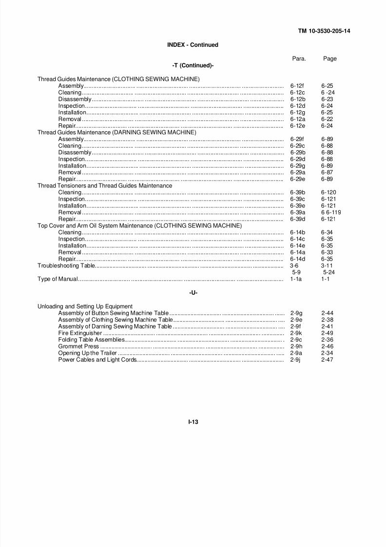
8/7/2019 TM 10-3530-205-10 CLOTHING REPAIR SHOP
http://slidepdf.com/reader/full/tm-10-3530-205-10-clothing-repair-shop 441/455
TM 10-3530-205-14
INDEX - Continued
Para. Page-T (Continued)-
Thread Guides Maintenance (CLOTHING SEWING MACHINE)
Assembly................................ ................................ ................................ .......................... 6-12f 6-25Cleaning................................ ................................ ................................ ........................... 6-12c 6 -24Disassembly................................ ................................ ................................ ..................... 6-12b 6-23Inspection................................ ................................ ................................ ......................... 6-12d 6-24Installation................................ ................................ ................................ ........................ 6-12g 6-25Removal ................................ ................................ ................................ ........................... 6-12a 6-22Repair................................ ................................ ................................ ............................... 6-12e 6-24
Thread Guides Maintenance (DARNING SEWING MACHINE)Assembly................................ ................................ ................................ .......................... 6-29f 6-89Cleaning................................ ................................ ................................ ........................... 6-29c 6-88Disassembly................................ ................................ ................................ ..................... 6-29b 6-88Inspection................................ ................................ ................................ ......................... 6-29d 6-88Installation................................ ................................ ................................ ........................ 6-29g 6-89Removal ................................ ................................ ................................ ........................... 6-29a 6-87Repair................................ ................................ ................................ ............................... 6-29e 6-89
Thread Tensioners and Thread Guides MaintenanceCleaning................................ ................................ ................................ ........................... 6-39b 6-120Inspection................................ ................................ ................................ ......................... 6-39c 6-121Installation................................ ................................ ................................ ........................ 6-39e 6-121Removal ................................ ................................ ................................ ........................... 6-39a 6 6-119Repair................................ ................................ ................................ ............................... 6-39d 6-121
Top Cover and Arm Oil System Maintenance (CLOTHING SEWING MACHINE)Cleaning................................ ................................ ................................ ........................... 6-14b 6-34Inspection................................ ................................ ................................ ......................... 6-14c 6-35Installation................................ ................................ ................................ ........................ 6-14e 6-35Removal ................................ ................................ ................................ ........................... 6-14a 6-33Repair................................ ................................ ................................ ............................... 6-14d 6-35
Troubleshooting Table................................ ................................ ................................ ................... 3-6 3-115-9 5-24
Type of Manual................................ ................................ ................................ ............................. 1-1a 1-1
-U-
Unloading and Setting Up EquipmentAssembly of Button Sewing Machine Table ................................ ................................ ...... 2-9g 2-44Assembly of Clothing Sewing Machine Table................................ ................................ .... 2-9e 2-38Assembly of Darning Sewing Machine Table ................................ ................................ .... 2-9f 2-41Fire Extinguisher ................................ ................................ ................................ .............. 2-9k 2-49Folding Table Assemblies................................ ................................ ................................ . 2-9c 2-36Grommet Press ................................ ................................ ................................ ................ 2-9h 2-46
Opening Up the Trailer ................................ ................................ ................................ ..... 2-9a 2-34Power Cables and Light Cords................................ ................................ .......................... 2-9j 2-47
I-13
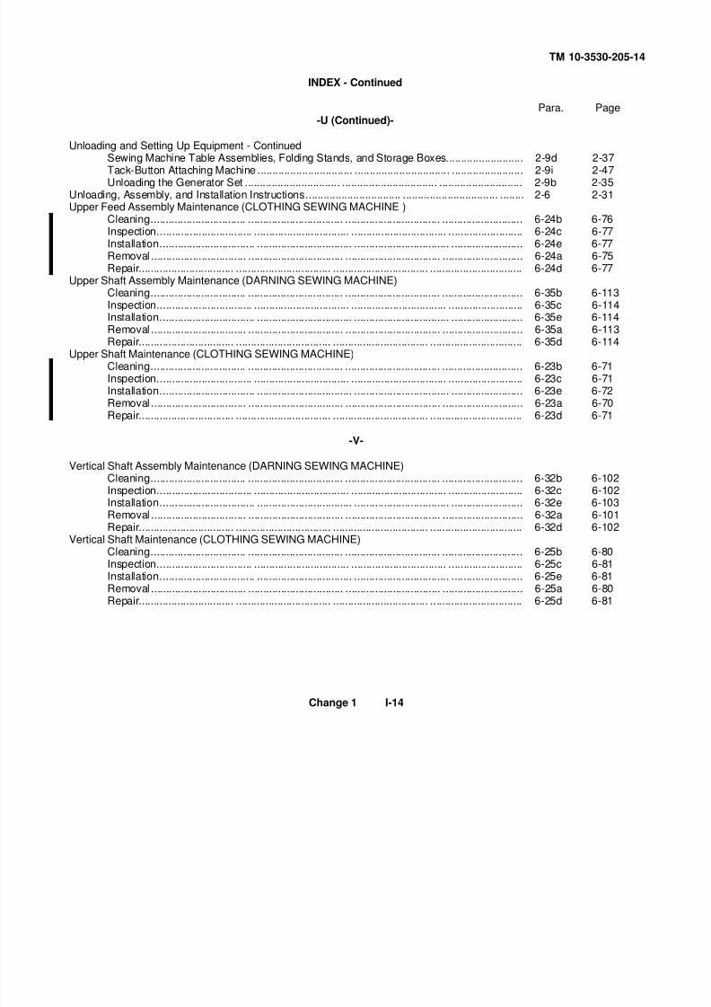
8/7/2019 TM 10-3530-205-10 CLOTHING REPAIR SHOP
http://slidepdf.com/reader/full/tm-10-3530-205-10-clothing-repair-shop 442/455
TM 10-3530-205-14
INDEX - Continued
Para. Page-U (Continued)-
Unloading and Setting Up Equipment - Continued
Sewing Machine Table Assemblies, Folding Stands, and Storage Boxes.......................... 2-9d 2-37Tack-Button Attaching Machine ................................ ................................ ........................ 2-9i 2-47Unloading the Generator Set ................................ ................................ ............................ 2-9b 2-35
Unloading, Assembly, and Installation Instructions................................ ................................ ........ 2-6 2-31Upper Feed Assembly Maintenance (CLOTHING SEWING MACHINE )
Cleaning................................ ................................ ................................ ........................... 6-24b 6-76Inspection................................ ................................ ................................ ......................... 6-24c 6-77Installation................................ ................................ ................................ ........................ 6-24e 6-77Removal ................................ ................................ ................................ ........................... 6-24a 6-75Repair................................ ................................ ................................ ............................... 6-24d 6-77
Upper Shaft Assembly Maintenance (DARNING SEWING MACHINE)Cleaning................................ ................................ ................................ ........................... 6-35b 6-113Inspection................................ ................................ ................................ ......................... 6-35c 6-114Installation................................ ................................ ................................ ........................ 6-35e 6-114Removal ................................ ................................ ................................ ........................... 6-35a 6-113Repair................................ ................................ ................................ ............................... 6-35d 6-114
Upper Shaft Maintenance (CLOTHING SEWING MACHINE)Cleaning................................ ................................ ................................ ........................... 6-23b 6-71Inspection................................ ................................ ................................ ......................... 6-23c 6-71Installation................................ ................................ ................................ ........................ 6-23e 6-72Removal ................................ ................................ ................................ ........................... 6-23a 6-70Repair................................ ................................ ................................ ............................... 6-23d 6-71
-V-
Vertical Shaft Assembly Maintenance (DARNING SEWING MACHINE)Cleaning................................ ................................ ................................ ........................... 6-32b 6-102Inspection................................ ................................ ................................ ......................... 6-32c 6-102Installation................................ ................................ ................................ ........................ 6-32e 6-103Removal ................................ ................................ ................................ ........................... 6-32a 6-101Repair................................ ................................ ................................ ............................... 6-32d 6-102
Vertical Shaft Maintenance (CLOTHING SEWING MACHINE)Cleaning................................ ................................ ................................ ........................... 6-25b 6-80Inspection................................ ................................ ................................ ......................... 6-25c 6-81Installation................................ ................................ ................................ ........................ 6-25e 6-81Removal ................................ ................................ ................................ ........................... 6-25a 6-80Repair................................ ................................ ................................ ............................... 6-25d 6-81
Change 1 I-14
8/7/2019 TM 10-3530-205-10 CLOTHING REPAIR SHOP
http://slidepdf.com/reader/full/tm-10-3530-205-10-clothing-repair-shop 443/455
TM 10-3530-205-14
By Order of the Secretary of the Army:
JOHN A. WICKHAM, JR.General, United States Army
Official: Chief of Staff
DONALD J. DELANDROBrigadier General, United States Army The Adjutant General
DISTRIBUTION:To be distributed in accordance with DA Form 12-25A, Operator, Organizational, Direct and General Support
Maintenance Requirements for Clothing and Textile Repair.
*U.S. GOVERNMENT PRINTING OFFICE: 1985-564-126/10158

8/7/2019 TM 10-3530-205-10 CLOTHING REPAIR SHOP
http://slidepdf.com/reader/full/tm-10-3530-205-10-clothing-repair-shop 444/455
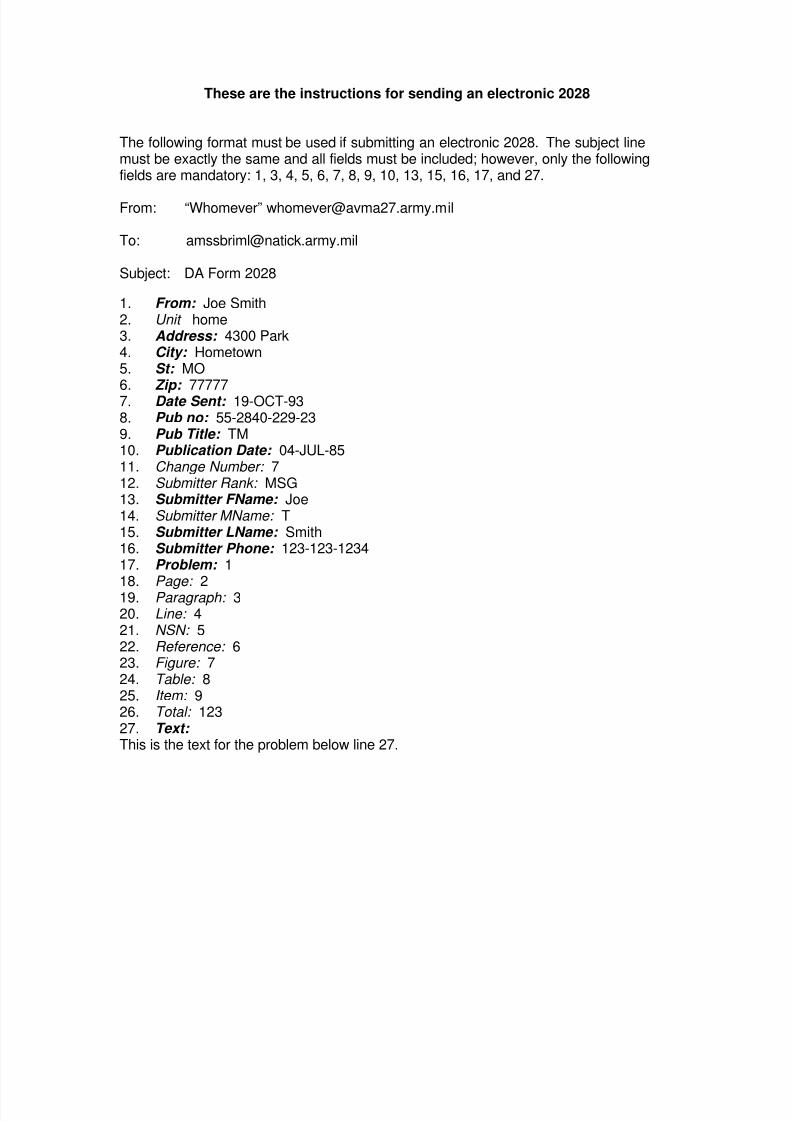
8/7/2019 TM 10-3530-205-10 CLOTHING REPAIR SHOP
http://slidepdf.com/reader/full/tm-10-3530-205-10-clothing-repair-shop 445/455
These are the instructions for sending an electronic 2028
The following format must be used if submitting an electronic 2028. The subject linemust be exactly the same and all fields must be included; however, only the following
fields are mandatory: 1, 3, 4, 5, 6, 7, 8, 9, 10, 13, 15, 16, 17, and 27.From: “Whomever” [email protected]
Subject: DA Form 2028
1. From: Joe Smith2. Unit home3. Address: 4300 Park4. City: Hometown5. St: MO6. Zip: 777777. Date Sent: 19-OCT-938. Pub no: 55-2840-229-239. Pub Title: TM10. Publication Date: 04-JUL-8511. Change Number: 712. Submitter Rank: MSG13. Submitter FName: Joe14. Submitter MName: T15. Submitter LName: Smith16. Submitter Phone: 123-123-123417. Problem: 118. Page: 219. Paragraph: 320. Line: 421. NSN: 522. Reference: 623. Figure: 724. Table: 825. Item: 926. Total: 12327. Text: This is the text for the problem below line 27.

8/7/2019 TM 10-3530-205-10 CLOTHING REPAIR SHOP
http://slidepdf.com/reader/full/tm-10-3530-205-10-clothing-repair-shop 446/455
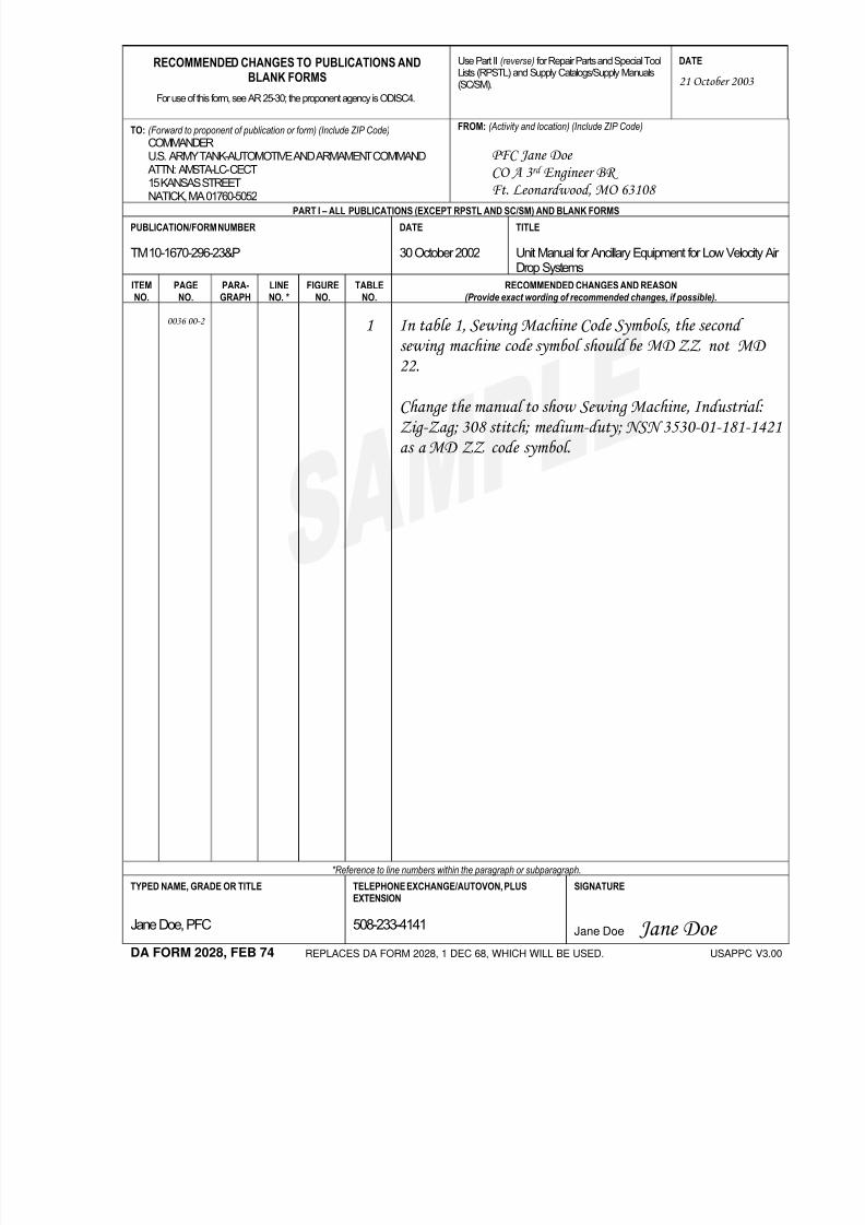
8/7/2019 TM 10-3530-205-10 CLOTHING REPAIR SHOP
http://slidepdf.com/reader/full/tm-10-3530-205-10-clothing-repair-shop 447/455
RECOMMENDED CHANGES TO PUBLICATIONS ANDBLANK FORMS
For use of this form, see AR 25-30; the proponent agency is ODISC4.
Use Part II (reverse) for Repair Parts and Special ToolLists (RPSTL) and Supply Catalogs/Supply Manuals(SC/SM).
DATE
21 October 2003
TO: (Forward to proponent of publication or form) (Include ZIP Code)COMMANDERU.S. ARMY TANK-AUTOMOTIVE AND ARMAMENT COMMANDATTN: AMSTA-LC-CECT15 KANSAS STREET
NATICK, MA 01760-5052
FROM: (Activity and location) (Include ZIP Code)
PFC Jane Doe CO A 3rd Engineer BR
Ft. Leonardwood, MO 63108
PART I – ALL PUBLICATIONS (EXCEPT RPSTL AND SC/SM) AND BLANK FORMS
PUBLICATION/FORM NUMBER
TM 10-1670-296-23&P
DATE
30 October 2002
TITLE
Unit Manual for Ancillary Equipment for Low Velocity Air Drop Systems
ITEMNO.
PAGENO.
PARA-GRAPH
LINENO. *
FIGURENO.
TABLENO.
RECOMMENDED CHANGES AND REASON(Provide exact wording of recommended changes, if possible).
0036 00-2 1 In table 1, Sewing Machine Code Symbols, the second sewing machine code symbol should be MD ZZ not M22.
Change the manual to show Sewing Machine, IndustriaZig-Zag; 308 stitch; medium-duty; NSN 3530-01-181-1as a MD ZZ code symbol.
*Reference to line numbers within the paragraph or subparagraph.
TYPED NAME, GRADE OR TITLE
Jane Doe, PFC
TELEPHONE EXCHANGE/AUTOVON, PLUSEXTENSION
508-233-4141
SIGNATURE
Jane Doe Jane Doe
DA FORM 2028, FEB 74 REPLACES DA FORM 2028, 1 DEC 68, WHICH WILL BE USED. USAPPC V3.00
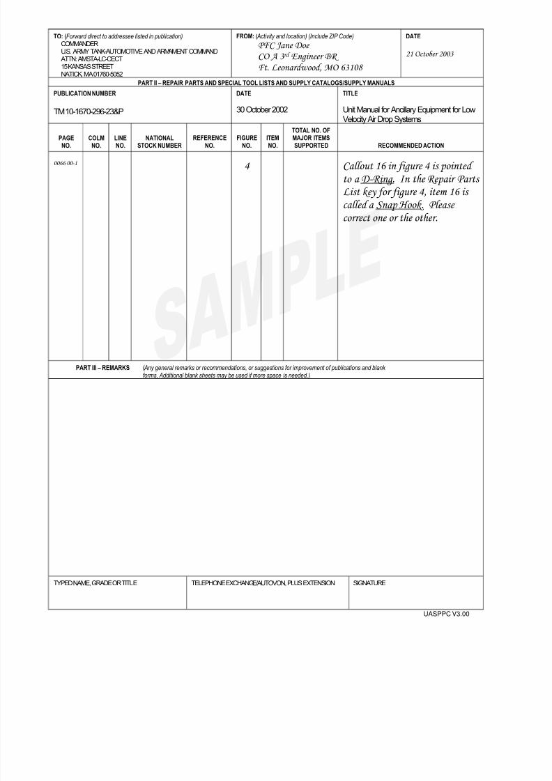
8/7/2019 TM 10-3530-205-10 CLOTHING REPAIR SHOP
http://slidepdf.com/reader/full/tm-10-3530-205-10-clothing-repair-shop 448/455
TO: (Forward direct to addressee listed in publication)COMMANDERU.S. ARMY TANK-AUTOMOTIVE AND ARMAMENT COMMANDATTN: AMSTA-LC-CECT15 KANSAS STREETNATICK, MA 01760-5052
FROM:( Activity and location) (Include ZIP Code)
PFC Jane Doe CO A 3rd Engineer BR Ft. Leonardwood, MO 63108
DATE
21 October 2003
PART II – REPAIR PARTS AND SPECIAL TOOL LISTS AND SUPPLY CATALOGS/SUPPLY MANUALS
PUBLICATION NUMBER
TM 10-1670-296-23&P
DATE
30 October 2002
TITLE
Unit Manual for Ancillary Equipment for LowVelocity Air Drop Systems
PAGENO.
COLMNO.
LINENO.
NATIONALSTOCK NUMBER
REFERENCENO.
FIGURENO.
ITEMNO.
TOTAL NO. OFMAJOR ITEMSSUPPORTED RECOMMENDED ACTION
0066 00-1 4 Callout 16 in figure 4 is pointed to a D-Ring. In the Repair Parts List key for figure 4, item 16 is called a Snap Hook. Please correct one or the other.
PART III – REMARKS ( Any general remarks or recommendations, or suggestions for improvement of publications and blank
forms. Additional blank sheets may be used if more space is needed.)
TYPED NAME, GRADE OR TITLE TELEPHONE EXCHANGE/AUTOVON, PLUS EXTENSION SIGNATURE
UASPPC V3.00

8/7/2019 TM 10-3530-205-10 CLOTHING REPAIR SHOP
http://slidepdf.com/reader/full/tm-10-3530-205-10-clothing-repair-shop 449/455
RECOMMENDED CHANGES TO PUBLICATIONS ANDBLANK FORMS
For use of this form, see AR 25-30; the proponent agency is ODISC4.
Use Part II(reverse) for Repair Parts and Special ToolLists (RPSTL) and Supply Catalogs/Supply Manuals(SC/SM).
DATE
TO: (Forward to proponent of publication or form) (Include ZIP Code)COMMANDERU.S. ARMYTANK-AUTOMOTIVE AND ARMAMENT COMMANDATTN: AMSTA-LC-CECT15 KANSAS STREETNATICK, MA 01760-5052
FROM: (Activity and location) (Include ZIP Code)
PART I – ALL PUBLICATIONS (EXCEPT RPSTL AND SC/SM) AND BLANK FORMS
PUBLICATION/FORM NUMBERTM 10-3530-205-14
DATE15 April 1985
TITLEOperator’s, Organizational, Direct Support and GenerSupport Maintenance Manual for Clothing Repair ShTrailer Mounted, Model CRS
ITEMNO.
PAGENO.
PARA-GRAPH
LINENO. *
FIGURENO.
TABLENO.
RECOMMENDED CHANGES AND REASON(Provide exact wording of recommended changes, if possible).
*Reference to line numbers within the paragraph or subparagraph.
TYPED NAME, GRADE OR TITLE TELEPHONE EXCHANGE/AUTOVON, PLUSEXTENSION
SIGNATURE
DA FORM 2028, FEB 74 REPLACES DA FORM 2028, 1 DEC 68, WHICH WILL BE USED. USAPPC V3.00

8/7/2019 TM 10-3530-205-10 CLOTHING REPAIR SHOP
http://slidepdf.com/reader/full/tm-10-3530-205-10-clothing-repair-shop 450/455
TO: (Forward direct to addressee listed in publication)COMMANDERU.S. ARMYTANK-AUTOMOTIVE AND ARMAMENT COMMANDATTN: AMSTA-LC-CECT15 KANSAS STREETNATICK, MA 01760-5052
FROM:( Activity and location) (Include ZIP Code) DATE
PART II – REPAIR PARTS AND SPECIAL TOOL LISTS AND SUPPLY CATALOGS/SUPPLY MANUALS
PUBLICATION NUMBERTM 10-3530-205-14
DATE15 April 1985
TITLEOperator’s, Organizational, Direct Support and GeneralSupport Maintenance Manual for Clothing Repair Shop,Trailer Mounted, Model CRS
PAGE
NO.
COLM
NO.
LINE
NO.
NATIONAL STOCK
NUMBER
REFERENCE
NO.
FIGURE
NO.
ITEM
NO.
TOTAL NO.OF MAJOR
ITEMSSUPPORTED RECOMMENDED ACTION
PART III – REMARKS ( Any general remarks or recommendations, or suggestions for improvement of publications and blank forms. Additional blank sheets may be used if more space is needed.)
TYPED NAME, GRADE OR TITLE TELEPHONE EXCHANGE/AUTOVON, PLUS EXTENSION SIGNATURE
UASPPC V3.00
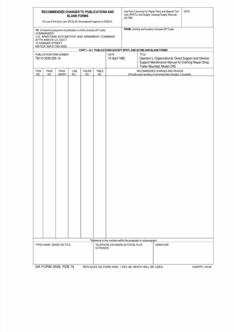
8/7/2019 TM 10-3530-205-10 CLOTHING REPAIR SHOP
http://slidepdf.com/reader/full/tm-10-3530-205-10-clothing-repair-shop 451/455
RECOMMENDED CHANGES TO PUBLICATIONS ANDBLANK FORMS
For use of this form, see AR 25-30; the proponent agency is ODISC4.
Use Part II(reverse) for Repair Parts and Special ToolLists (RPSTL) and Supply Catalogs/Supply Manuals(SC/SM).
DATE
TO: (Forward to proponent of publication or form) (Include ZIP Code)COMMANDERU.S. ARMYTANK-AUTOMOTIVE AND ARMAMENT COMMANDATTN: AMSTA-LC-CECT15 KANSAS STREETNATICK, MA 01760-5052
FROM: (Activity and location) (Include ZIP Code)
PART I – ALL PUBLICATIONS (EXCEPT RPSTL AND SC/SM) AND BLANK FORMS
PUBLICATION/FORM NUMBERTM 10-3530-205-14
DATE15 April 1985
TITLEOperator’s, Organizational, Direct Support and GenerSupport Maintenance Manual for Clothing Repair ShTrailer Mounted, Model CRS
ITEMNO.
PAGENO.
PARA-GRAPH
LINENO. *
FIGURENO.
TABLENO.
RECOMMENDED CHANGES AND REASON(Provide exact wording of recommended changes, if possible).
*Reference to line numbers within the paragraph or subparagraph.
TYPED NAME, GRADE OR TITLE TELEPHONE EXCHANGE/AUTOVON, PLUSEXTENSION
SIGNATURE
DA FORM 2028, FEB 74 REPLACES DA FORM 2028, 1 DEC 68, WHICH WILL BE USED. USAPPC V3.00

8/7/2019 TM 10-3530-205-10 CLOTHING REPAIR SHOP
http://slidepdf.com/reader/full/tm-10-3530-205-10-clothing-repair-shop 452/455
TO: (Forward direct to addressee listed in publication)COMMANDERU.S. ARMYTANK-AUTOMOTIVE AND ARMAMENT COMMANDATTN: AMSTA-LC-CECT15 KANSAS STREETNATICK, MA 01760-5052
FROM:( Activity and location) (Include ZIP Code) DATE
PART II – REPAIR PARTS AND SPECIAL TOOL LISTS AND SUPPLY CATALOGS/SUPPLY MANUALS
PUBLICATION NUMBERTM 10-3530-205-14
DATE15 April 1985
TITLEOperator’s, Organizational, Direct Support and GeneralSupport Maintenance Manual for Clothing Repair Shop,Trailer Mounted, Model CRS
PAGE
NO.
COLM
NO.
LINE
NO.
NATIONAL STOCK
NUMBER
REFERENCE
NO.
FIGURE
NO.
ITEM
NO.
TOTAL NO.OF MAJOR
ITEMSSUPPORTED RECOMMENDED ACTION
PART III – REMARKS ( Any general remarks or recommendations, or suggestions for improvement of publications and blank forms. Additional blank sheets may be used if more space is needed.)
TYPED NAME, GRADE OR TITLE TELEPHONE EXCHANGE/AUTOVON, PLUS EXTENSION SIGNATURE
UASPPC V3.00

8/7/2019 TM 10-3530-205-10 CLOTHING REPAIR SHOP
http://slidepdf.com/reader/full/tm-10-3530-205-10-clothing-repair-shop 453/455
RECOMMENDED CHANGES TO PUBLICATIONS ANDBLANK FORMS
For use of this form, see AR 25-30; the proponent agency is ODISC4.
Use Part II(reverse) for Repair Parts and Special ToolLists (RPSTL) and Supply Catalogs/Supply Manuals(SC/SM).
DATE
TO: (Forward to proponent of publication or form) (Include ZIP Code)COMMANDERU.S. ARMYTANK-AUTOMOTIVE AND ARMAMENT COMMANDATTN: AMSTA-LC-CECT15 KANSAS STREETNATICK, MA 01760-5052
FROM: (Activity and location) (Include ZIP Code)
PART I – ALL PUBLICATIONS (EXCEPT RPSTL AND SC/SM) AND BLANK FORMS
PUBLICATION/FORM NUMBERTM 10-3530-205-14
DATE15 April 1985
TITLEOperator’s, Organizational, Direct Support and GenerSupport Maintenance Manual for Clothing Repair ShTrailer Mounted, Model CRS
ITEMNO.
PAGENO.
PARA-GRAPH
LINENO. *
FIGURENO.
TABLENO.
RECOMMENDED CHANGES AND REASON(Provide exact wording of recommended changes, if possible).
*Reference to line numbers within the paragraph or subparagraph.
TYPED NAME, GRADE OR TITLE TELEPHONE EXCHANGE/AUTOVON, PLUSEXTENSION
SIGNATURE
DA FORM 2028, FEB 74 REPLACES DA FORM 2028, 1 DEC 68, WHICH WILL BE USED. USAPPC V3.00
8/7/2019 TM 10-3530-205-10 CLOTHING REPAIR SHOP
http://slidepdf.com/reader/full/tm-10-3530-205-10-clothing-repair-shop 454/455
TO: (Forward direct to addressee listed in publication)COMMANDERU.S. ARMYTANK-AUTOMOTIVE AND ARMAMENT COMMANDATTN: AMSTA-LC-CECT15 KANSAS STREETNATICK, MA 01760-5052
FROM:( Activity and location) (Include ZIP Code) DATE
PART II – REPAIR PARTS AND SPECIAL TOOL LISTS AND SUPPLY CATALOGS/SUPPLY MANUALS
PUBLICATION NUMBERTM 10-3530-205-14
DATE15 April 1985
TITLEOperator’s, Organizational, Direct Support and GeneralSupport Maintenance Manual for Clothing Repair Shop,Trailer Mounted, Model CRS
PAGE
NO.
COLM
NO.
LINE
NO.
NATIONAL STOCK
NUMBER
REFERENCE
NO.
FIGURE
NO.
ITEM
NO.
TOTAL NO.OF MAJOR
ITEMSSUPPORTED RECOMMENDED ACTION
PART III – REMARKS ( Any general remarks or recommendations, or suggestions for improvement of publications and blank forms. Additional blank sheets may be used if more space is needed.)
TYPED NAME, GRADE OR TITLE TELEPHONE EXCHANGE/AUTOVON, PLUS EXTENSION SIGNATURE
UASPPC V3.00
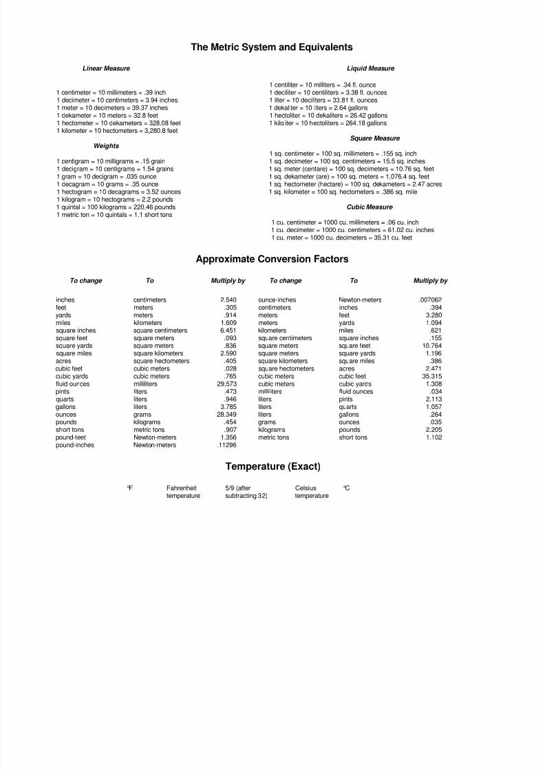
8/7/2019 TM 10-3530-205-10 CLOTHING REPAIR SHOP
http://slidepdf.com/reader/full/tm-10-3530-205-10-clothing-repair-shop 455/455
The Metric System and Equivalents
Linear Measure Liquid Measure
1 centiliter = 10 milliters = .34 fl. ounce1 centimeter = 10 millimeters = .39 inch 1 deciliter = 10 centiliters = 3.38 fl. ounces1 decimeter = 10 centimeters = 3.94 inches 1 liter = 10 deciliters = 33.81 fl. ounces1 meter = 10 decimeters = 39.37 inches 1 dekaliter = 10 liters = 2.64 gallons1 dekameter = 10 meters = 32.8 feet 1 hectoliter = 10 dekaliters = 26.42 gallons
1 hectometer = 10 dekameters = 328.08 feet 1 kiloliter = 10 hectoliters = 264.18 gallons1 kilometer = 10 hectometers = 3,280.8 feetSquare Measure
Weights 1 sq. centimeter = 100 sq. millimeters = .155 sq. inch
1 centigram = 10 milligrams = .15 grain 1 sq. decimeter = 100 sq. centimeters = 15.5 sq. inches1 decigram = 10 centigrams = 1.54 grains 1 sq. meter (centare) = 100 sq. decimeters = 10.76 sq. feet1 gram = 10 decigram = .035 ounce 1 sq. dekameter (are) = 100 sq. meters = 1,076.4 sq. feet1 decagram = 10 grams = .35 ounce 1 sq. hectometer (hectare) = 100 sq. dekameters = 2.47 acres1 hectogram = 10 decagrams = 3.52 ounces 1 sq. kilometer = 100 sq. hectometers = .386 sq. mile1 kilogram = 10 hectograms = 2.2 pounds1 quintal = 100 kilograms = 220.46 pounds Cubic Measure 1 metric ton = 10 quintals = 1.1 short tons
1 cu. centimeter = 1000 cu. millimeters = .06 cu. inch1 cu. decimeter = 1000 cu. centimeters = 61.02 cu. inches1 cu. meter = 1000 cu. decimeters = 35.31 cu. feet
Approximate Conversion Factors
To change To Multiply by To change To Multiply by
inches centimeters 2.540 ounce-inches Newton-meters .007062feet meters .305 centimeters inches .394yards meters .914 meters feet 3.280miles kilometers 1.609 meters yards 1.094square inches square centimeters 6.451 kilometers miles .621square feet square meters .093 square centimeters square inches .155square yards square meters .836 square meters square feet 10.764square miles square kilometers 2.590 square meters square yards 1.196acres square hectometers .405 square kilometers square miles .386cubic feet cubic meters .028 square hectometers acres 2.471cubic yards cubic meters 765 cubic meters cubic feet 35 315