Embed Size (px)
Citation preview
1/17/2012
TAO-3530 USER’S GUIDE 096 | 1/17/2012, TechNexion
SOM TAO-3530 SYSTEM ON MODULE
TAO-3530 USER’S GUIDE 096
1/17/2012, TechNexion
2
TAO-3530
TAO-3530 System on Module
and its Baseboards
User‟s Guide
Rev 0.96
TAO-3530 USER’S GUIDE 096
1/17/2012, TechNexion
3
1 Contents 2 Care and maintenance ..................................................................................................................... 7
2.1 General .................................................................................................................................... 7
2.2 Regulatory information ............................................................................................................ 7
3 Introduction .................................................................................................................................. 10
4 Get started .................................................................................................................................... 11
4.1 First time use Tsunami baseboard XL (7” LCD) ........................................................................ 11
4.2 First time use Tsunami baseboard (4.3” LCD) .......................................................................... 14
4.3 First time use Thunder baseboard .......................................................................................... 17
4.4 First time use Inferno baseboard ............................................................................................ 21
4.5 Explanation of the TAO-3530W System on Module ................................................................ 25
4.6 Explanation of the TAO-3530 System on Module .................................................................... 26
4.7 Explanation of the Tsunami Baseboard ................................................................................... 27
4.8 Explanation of the Thunder Baseboard ................................................................................... 30
4.9 Explanation of the Inferno Baseboard .................................................................................... 32
5 Mechanical Dimensions ................................................................................................................. 34
5.1 Inferno Baseboard dimensions ............................................................................................... 34
5.2 Thunder Baseboard dimensions ............................................................................................. 34
5.3 Tsunami Baseboard dimensions ............................................................................................. 35
6 Harddisk placement (Tsunami) ....................................................................................................... 36
7 Downloads and drivers .................................................................................................................. 37
8 Software – Factory Default Screen ................................................................................................. 38
8.1 Automatic check for updates .................................................................................................. 38
8.2 Installing Linux ....................................................................................................................... 39
8.3 Installing Android ................................................................................................................... 39
8.4 What to do if your development kit does not have the factory default screen ........................ 40
8.4.1 Create the SD-card with the rescue image in a Windows environment ........................... 40
8.4.2 Create the SD-card with the rescue image in a Linux environment .................................. 43
8.4.3 Installing the rescue image on the baseboard with the SD-card ...................................... 45
8.4.4 Factory Default Home Screen ......................................................................................... 46
9 Connecting a null modem cable ..................................................................................................... 47
TAO-3530 USER’S GUIDE 096
1/17/2012, TechNexion
4
10 Software – Linux ........................................................................................................................ 53
10.1 Introduction ........................................................................................................................... 53
10.1 Quick install guide for installing a cross-compiler. .................................................................. 53
10.2 XUKR build instructions .......................................................................................................... 54
10.2.1 X-loader.......................................................................................................................... 54
10.2.2 U-boot ............................................................................................................................ 55
10.2.3 Kernel ............................................................................................................................. 55
10.2.4 Root filesystem ............................................................................................................... 56
10.3 Compiling for TAO-3530 ......................................................................................................... 56
10.3.1 QT .................................................................................................................................. 57
10.4 Basic components of a bootable Linux SD card: ...................................................................... 57
10.5 Manual NAND Installation ...................................................................................................... 58
10.6 How to ................................................................................................................................... 60
10.6.1 How to calibrate the touch screen in Linux ..................................................................... 60
10.6.2 How to use OPKG ........................................................................................................... 61
10.6.3 How to enable wireless .................................................................................................. 62
10.6.4 How to do low level debugging (advanced) ..................................................................... 63
11 Software - Android ..................................................................................................................... 64
11.1 How to install an Android application on TechNexion baseboards .......................................... 64
11.2 How to install an android application with an internet connection ......................................... 70
11.3 ADB - Installing applications ................................................................................................... 77
11.3.1 Windows ........................................................................................................................ 77
11.3.2 Linux .............................................................................................................................. 83
11.3.3 ADB Functions ................................................................................................................ 85
12 Software - Windows CE .............................................................................................................. 86
12.1 Warning ................................................................................................................................. 86
12.2 Update to Windows Embedded CE6.0 R3 ............................................................................... 86
12.3 Get the BSP ............................................................................................................................ 86
12.3.1 Download the BSP from the web-Site ............................................................................. 86
12.3.2 Install BSP to “Platform Builder for CE 6.0”. .................................................................... 86
12.4 Create a SD card ..................................................................................................................... 92
TAO-3530 USER’S GUIDE 096
1/17/2012, TechNexion
5
12.5 How to put the WinCE image in the NAND Flash .................................................................. 104
12.5.1 Create file “NK.nb0”. .................................................................................................... 104
12.5.2 Write the Bootloader and OS image to the NAND Flash. ............................................... 108
12.5.3 Boot from NAND flash. ................................................................................................. 121
12.6 Create a new project using TN_TAO_3530 BSP ..................................................................... 126
12.6.1 Compile project. ........................................................................................................... 138
12.7 How to change the logo that you see during boot up ........................................................... 144
12.7.1 Preparing the BMP ....................................................................................................... 144
12.7.2 Change the makefile.inc ............................................................................................... 144
12.7.3 Calculate the needed blocks ......................................................................................... 144
12.7.4 Change image-cfg.h ...................................................................................................... 146
12.7.5 Compile ........................................................................................................................ 146
12.7.6 Put in NAND ................................................................................................................. 146
13 Appendix – Module .................................................................................................................. 147
13.1 TAO-3530 System on Module Dimensions ............................................................................ 147
13.2 Module Connectors .............................................................................................................. 148
13.3 Nut to Fix TAO-3530 Module to the Baseboard .................................................................... 149
13.4 TAO-3530 JTAG Solder points ............................................................................................... 150
14 Appendix - Schematics ............................................................................................................. 152
14.1 Inferno baseboard schematics .............................................................................................. 152
14.2 Thunder baseboard schematics ............................................................................................ 157
14.3 Tsunami baseboard schematics ............................................................................................ 164
15 Appendix - Pin outs .................................................................................................................. 174
15.1 Module connector B1 ........................................................................................................... 174
15.2 Module connector B2 ........................................................................................................... 176
15.3 SPI1 ...................................................................................................................................... 179
15.4 UART 3 ................................................................................................................................. 180
15.5 Pin header for VGA connector .............................................................................................. 181
15.6 LVDS connector .................................................................................................................... 182
15.7 Thunder expansion pin header ............................................................................................. 184
15.8 Battery connector ................................................................................................................ 186
TAO-3530 USER’S GUIDE 096
1/17/2012, TechNexion
6
15.9 Inferno Expansion Pin Header .............................................................................................. 187
15.10 RS-232 cable..................................................................................................................... 188
TAO-3530 USER’S GUIDE 096
1/17/2012, TechNexion
7
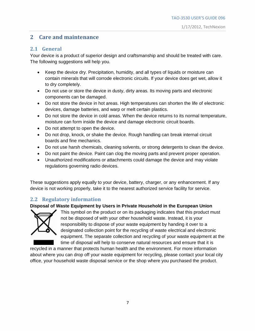
2 Care and maintenance
2.1 General Your device is a product of superior design and craftsmanship and should be treated with care.
The following suggestions will help you.
Keep the device dry. Precipitation, humidity, and all types of liquids or moisture can
contain minerals that will corrode electronic circuits. If your device does get wet, allow it
to dry completely.
Do not use or store the device in dusty, dirty areas. Its moving parts and electronic
components can be damaged.
Do not store the device in hot areas. High temperatures can shorten the life of electronic
devices, damage batteries, and warp or melt certain plastics.
Do not store the device in cold areas. When the device returns to its normal temperature,
moisture can form inside the device and damage electronic circuit boards.
Do not attempt to open the device.
Do not drop, knock, or shake the device. Rough handling can break internal circuit
boards and fine mechanics.
Do not use harsh chemicals, cleaning solvents, or strong detergents to clean the device.
Do not paint the device. Paint can clog the moving parts and prevent proper operation.
Unauthorized modifications or attachments could damage the device and may violate
regulations governing radio devices.
These suggestions apply equally to your device, battery, charger, or any enhancement. If any
device is not working properly, take it to the nearest authorized service facility for service.
2.2 Regulatory information Disposal of Waste Equipment by Users in Private Household in the European Union
This symbol on the product or on its packaging indicates that this product must
not be disposed of with your other household waste. Instead, it is your
responsibility to dispose of your waste equipment by handing it over to a
designated collection point for the recycling of waste electrical and electronic
equipment. The separate collection and recycling of your waste equipment at the
time of disposal will help to conserve natural resources and ensure that it is
recycled in a manner that protects human health and the environment. For more information
about where you can drop off your waste equipment for recycling, please contact your local city
office, your household waste disposal service or the shop where you purchased the product.
TAO-3530 USER’S GUIDE 096
1/17/2012, TechNexion
8
TAO-3530 USER’S GUIDE 096
1/17/2012, TechNexion
9
We hereby declare that the product is in compliance with the essential
requirements and other relevant provisions of European Directive 1999/5/EC
(radio equipment and telecommunications terminal equipment Directive).
Federal Communications Commission (FCC) Unintentional emitter per
FCC Part 15
This device has been tested and found to comply with the limits for a Class B
digital device, pursuant to Part 15 of the FCC rules. These limits are designed
to provide reasonable protection against harmful interference in a residential
installation. This equipment generates, uses, and can radiate radio frequency energy and, if not
installed and used in accordance with the instructions, may cause harmful interference to radio
or television reception. However, there is no guarantee that interference will not occur in a
particular installation. If this equipment does cause interference to radio and television reception,
which can be determined by turning the equipment off and on, the user is encouraged to try to
correct the interference by one or more of the following measures:
■ Reorient or relocate the receiving antenna
■ Increase the separation between the equipment and receiver
■ Connect the equipment to an outlet on a different circuit from that to which the receiver is
connected
■ Consult the dealer or an experienced radio/TV technician for help.
WARNING! To reduce the possibility of heat-related injuries or of overheating
the computer, do not place the computer directly on your lap or obstruct the
computer air vents. Use the computer only on a hard, flat surface. Do not allow
another hard surface, such as an adjoining optional printer, or a soft surface,
such as pillows or rugs or clothing, to block airflow. Also, do not allow the AC
adapter to contact the skin or a soft surface, such as pillows or rugs or clothing, during operation.
The computer and the AC adapter comply with the user-accessible surface temperature limits
defined by the International Standard for Safety of Information Technology Equipment (IEC
60950).
TAO-3530 USER’S GUIDE 096
1/17/2012, TechNexion
10
3 Introduction The TAO-3530 System on Module (SOM) is a small computer that can be clicked in a
baseboard with several IO‟s to form a full computer. Each base board can be developed with
IO‟s in different places and with different functions. The Idea behind the product is that anyone
can develop a base board suitable for their needs and just plug in the SOM. This will make the
system very flexible and faster to develop and cheaper than developing a single board solution,
because all the hard work is already completed within the SOM module.
Anybody can buy a TAO-3530 and a Baseboard from our website.
The development kits are meant to test your software on the platform. In the same time you can
develop your own baseboard with the IO‟s on the place you need. When your own baseboard is
ready, the module can be plugged into your own baseboard to complete the project.
The TAO-3530 system and its baseboards come in different versions, the user‟s guide is meant
as a general guide for all these versions. Pictures and details of the device can differ from the
actual purchased product. All specifications are subject to change without notice.
One can always check our website ( www.technexion.com ) for more details, to download this
user guide or to see other information.
TAO-3530 USER’S GUIDE 096
1/17/2012, TechNexion
11
4 Get started
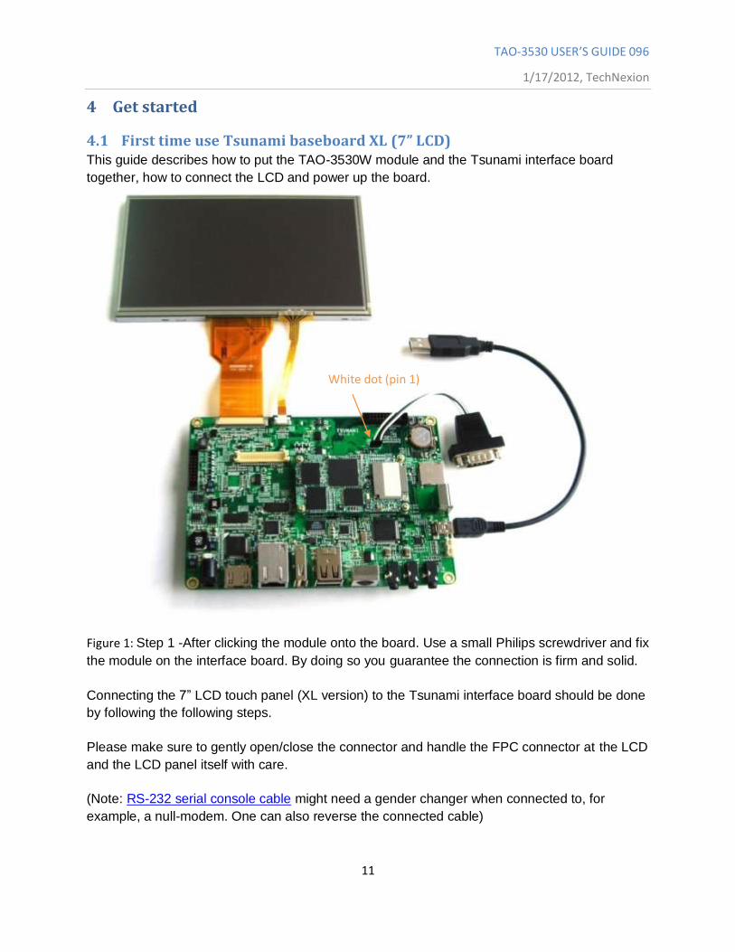
4.1 First time use Tsunami baseboard XL (7” LCD) This guide describes how to put the TAO-3530W module and the Tsunami interface board
together, how to connect the LCD and power up the board.
Figure 1: Step 1 -After clicking the module onto the board. Use a small Philips screwdriver and fix
the module on the interface board. By doing so you guarantee the connection is firm and solid.
Connecting the 7” LCD touch panel (XL version) to the Tsunami interface board should be done
by following the following steps.
Please make sure to gently open/close the connector and handle the FPC connector at the LCD
and the LCD panel itself with care.
(Note: RS-232 serial console cable might need a gender changer when connected to, for
example, a null-modem. One can also reverse the connected cable)
White dot (pin 1)
TAO-3530 USER’S GUIDE 096
1/17/2012, TechNexion
12
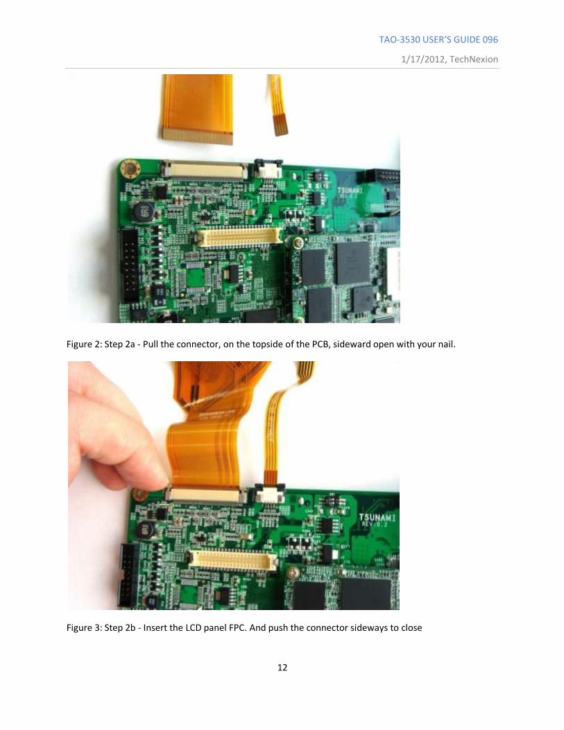
Figure 2: Step 2a - Pull the connector, on the topside of the PCB, sideward open with your nail.
Figure 3: Step 2b - Insert the LCD panel FPC. And push the connector sideways to close
TAO-3530 USER’S GUIDE 096
1/17/2012, TechNexion
13
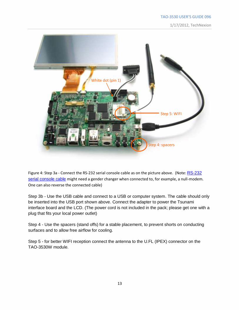
Figure 4: Step 3a - Connect the RS-232 serial console cable as on the picture above. (Note: RS-232
serial console cable might need a gender changer when connected to, for example, a null-modem.
One can also reverse the connected cable)
Step 3b - Use the USB cable and connect to a USB or computer system. The cable should only
be inserted into the USB port shown above. Connect the adapter to power the Tsunami
interface board and the LCD. (The power cord is not included in the pack; please get one with a
plug that fits your local power outlet)
Step 4 - Use the spacers (stand offs) for a stable placement, to prevent shorts on conducting
surfaces and to allow free airflow for cooling.
Step 5 - for better WIFI reception connect the antenna to the U.FL (IPEX) connector on the
TAO-3530W module.
White dot (pin 1)
Step 4: spacers
Step 5: WIFI
TAO-3530 USER’S GUIDE 096
1/17/2012, TechNexion
14
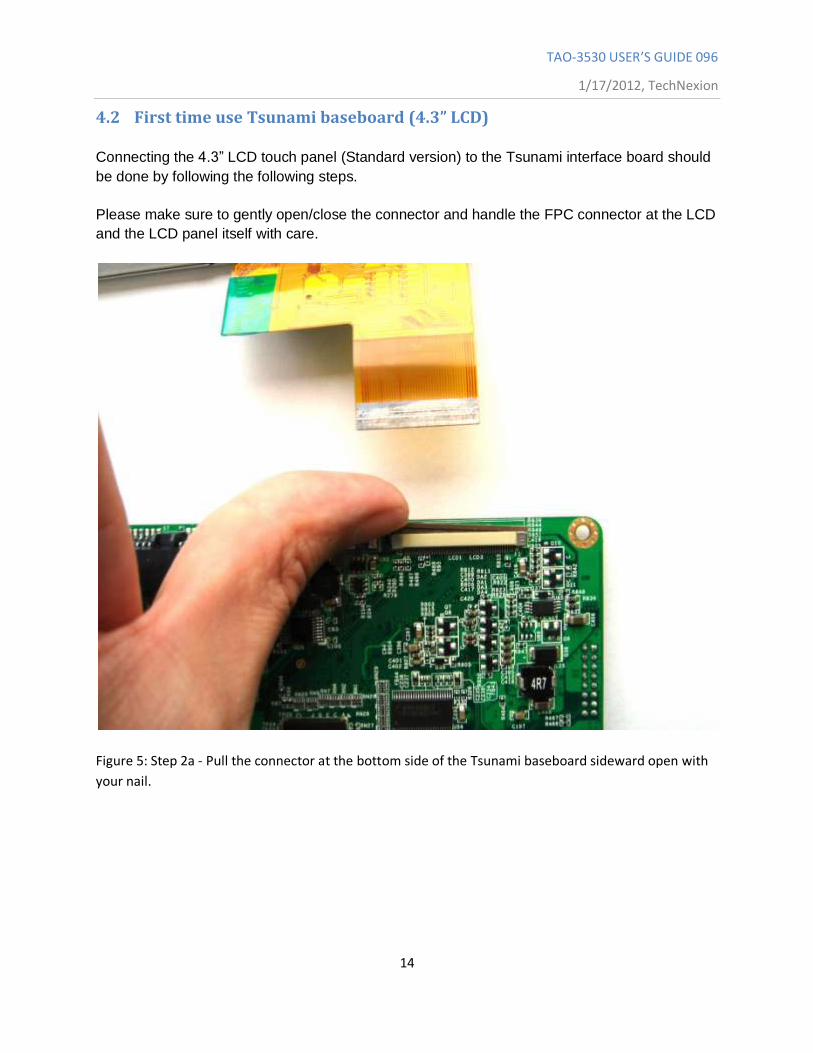
4.2 First time use Tsunami baseboard (4.3” LCD)
Connecting the 4.3” LCD touch panel (Standard version) to the Tsunami interface board should
be done by following the following steps.
Please make sure to gently open/close the connector and handle the FPC connector at the LCD
and the LCD panel itself with care.
Figure 5: Step 2a - Pull the connector at the bottom side of the Tsunami baseboard sideward open with
your nail.
TAO-3530 USER’S GUIDE 096
1/17/2012, TechNexion
15
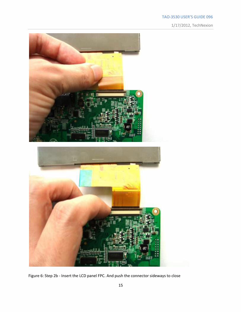
Figure 6: Step 2b - Insert the LCD panel FPC. And push the connector sideways to close
TAO-3530 USER’S GUIDE 096
1/17/2012, TechNexion
16
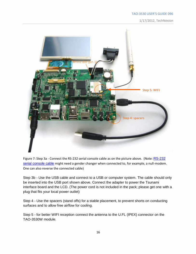
Figure 7: Step 3a - Connect the RS-232 serial console cable as on the picture above. (Note: RS-232
serial console cable might need a gender changer when connected to, for example, a null-modem.
One can also reverse the connected cable)
Step 3b - Use the USB cable and connect to a USB or computer system. The cable should only
be inserted into the USB port shown above. Connect the adapter to power the Tsunami
interface board and the LCD. (The power cord is not included in the pack; please get one with a
plug that fits your local power outlet)
Step 4 - Use the spacers (stand offs) for a stable placement, to prevent shorts on conducting
surfaces and to allow free airflow for cooling.
Step 5 - for better WIFI reception connect the antenna to the U.FL (IPEX) connector on the
TAO-3530W module.
White dot (pin 1)
Step 4: spacers
Step 5: WIFI
TAO-3530 USER’S GUIDE 096
1/17/2012, TechNexion
17
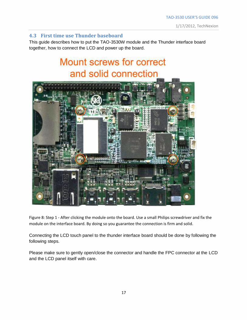
4.3 First time use Thunder baseboard This guide describes how to put the TAO-3530W module and the Thunder interface board
together, how to connect the LCD and power up the board.
Figure 8: Step 1 - After clicking the module onto the board. Use a small Philips screwdriver and fix the
module on the interface board. By doing so you guarantee the connection is firm and solid.
Connecting the LCD touch panel to the thunder interface board should be done by following the
following steps.
Please make sure to gently open/close the connector and handle the FPC connector at the LCD
and the LCD panel itself with care.
TAO-3530 USER’S GUIDE 096
1/17/2012, TechNexion
18
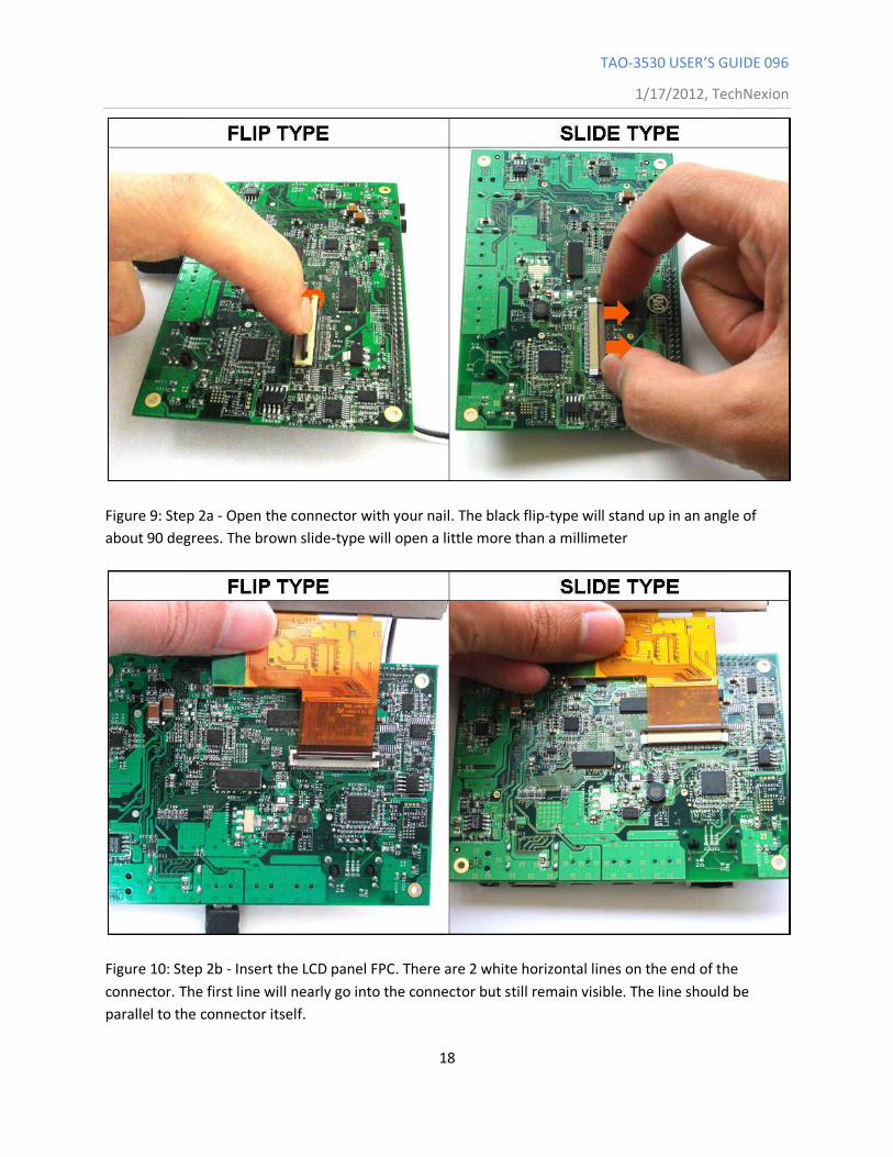
Figure 9: Step 2a - Open the connector with your nail. The black flip-type will stand up in an angle of
about 90 degrees. The brown slide-type will open a little more than a millimeter
Figure 10: Step 2b - Insert the LCD panel FPC. There are 2 white horizontal lines on the end of the
connector. The first line will nearly go into the connector but still remain visible. The line should be
parallel to the connector itself.
TAO-3530 USER’S GUIDE 096
1/17/2012, TechNexion
19
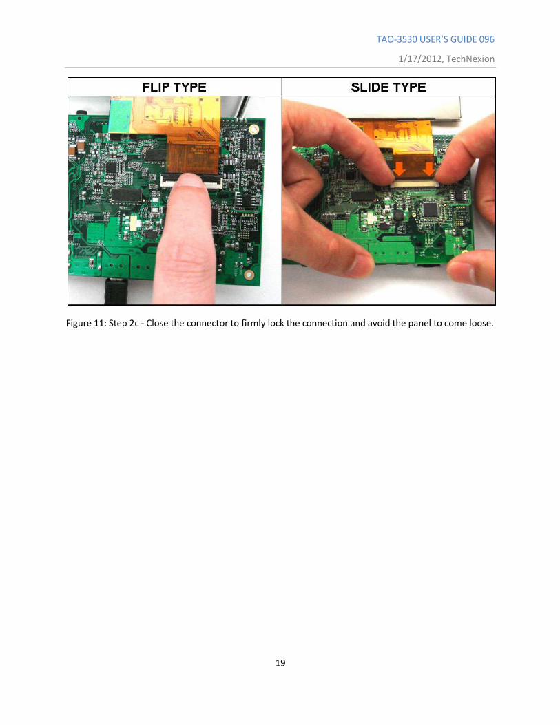
Figure 11: Step 2c - Close the connector to firmly lock the connection and avoid the panel to come loose.
TAO-3530 USER’S GUIDE 096
1/17/2012, TechNexion
20
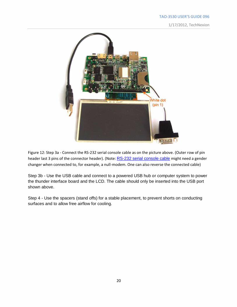
Figure 12: Step 3a - Connect the RS-232 serial console cable as on the picture above. (Outer row of pin
header last 3 pins of the connector header). (Note: RS-232 serial console cable might need a gender
changer when connected to, for example, a null-modem. One can also reverse the connected cable)
Step 3b - Use the USB cable and connect to a powered USB hub or computer system to power
the thunder interface board and the LCD. The cable should only be inserted into the USB port
shown above.
Step 4 - Use the spacers (stand offs) for a stable placement, to prevent shorts on conducting
surfaces and to allow free airflow for cooling.
TAO-3530 USER’S GUIDE 096
1/17/2012, TechNexion
21
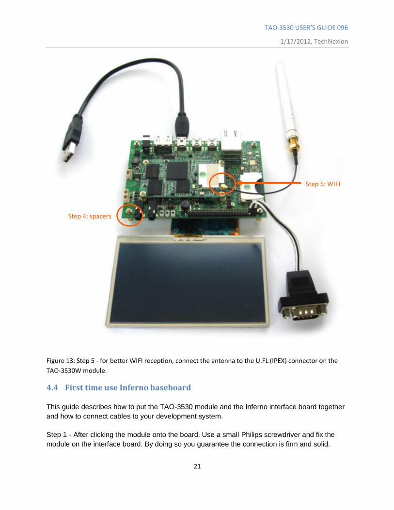
Figure 13: Step 5 - for better WIFI reception, connect the antenna to the U.FL (IPEX) connector on the
TAO-3530W module.
4.4 First time use Inferno baseboard
This guide describes how to put the TAO-3530 module and the Inferno interface board together
and how to connect cables to your development system.
Step 1 - After clicking the module onto the board. Use a small Philips screwdriver and fix the
module on the interface board. By doing so you guarantee the connection is firm and solid.
Step 4: spacers
Step 5: WIFI
TAO-3530 USER’S GUIDE 096
1/17/2012, TechNexion
22
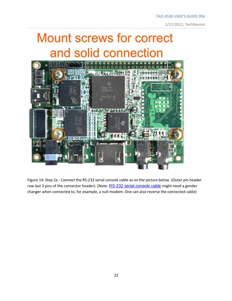
Figure 14: Step 2a - Connect the RS-232 serial console cable as on the picture below. (Outer pin header
row last 3 pins of the connector header). (Note: RS-232 serial console cable might need a gender
changer when connected to, for example, a null-modem. One can also reverse the connected cable)
TAO-3530 USER’S GUIDE 096
1/17/2012, TechNexion
23
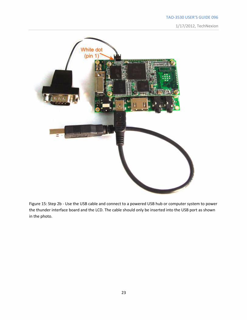
Figure 15: Step 2b - Use the USB cable and connect to a powered USB hub or computer system to power
the thunder interface board and the LCD. The cable should only be inserted into the USB port as shown
in the photo.
TAO-3530 USER’S GUIDE 096
1/17/2012, TechNexion
24
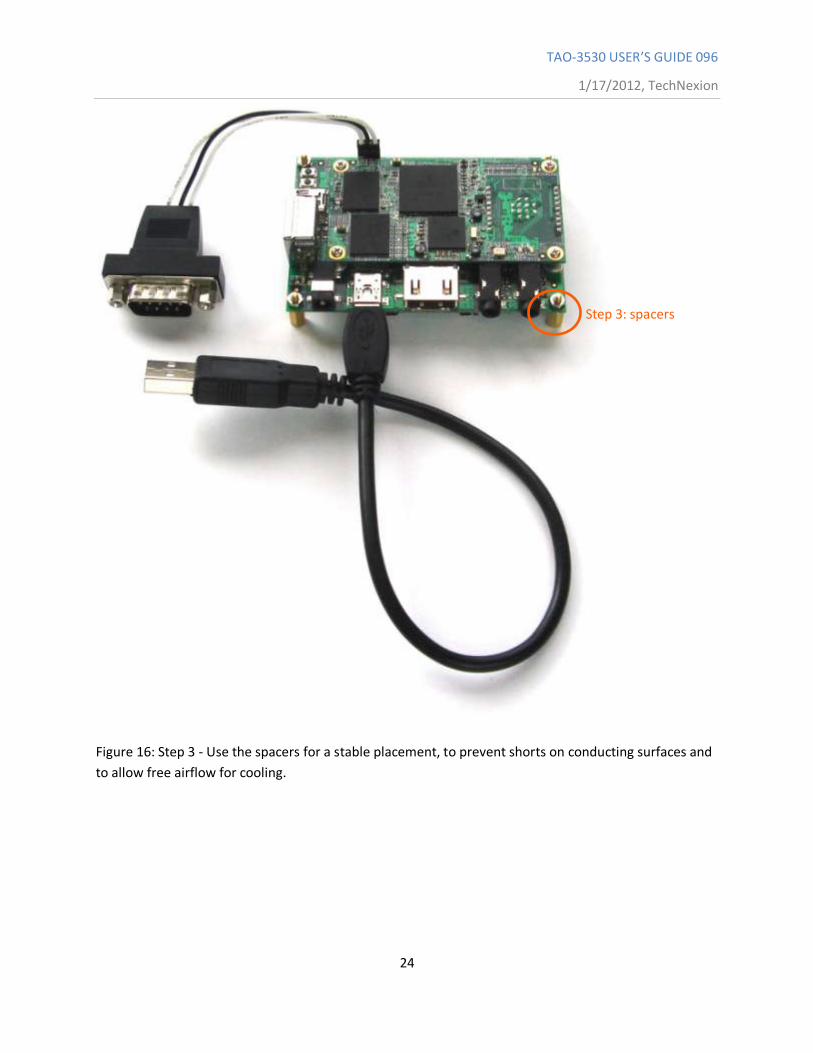
Figure 16: Step 3 - Use the spacers for a stable placement, to prevent shorts on conducting surfaces and
to allow free airflow for cooling.
Step 3: spacers
TAO-3530 USER’S GUIDE 096
1/17/2012, TechNexion
25
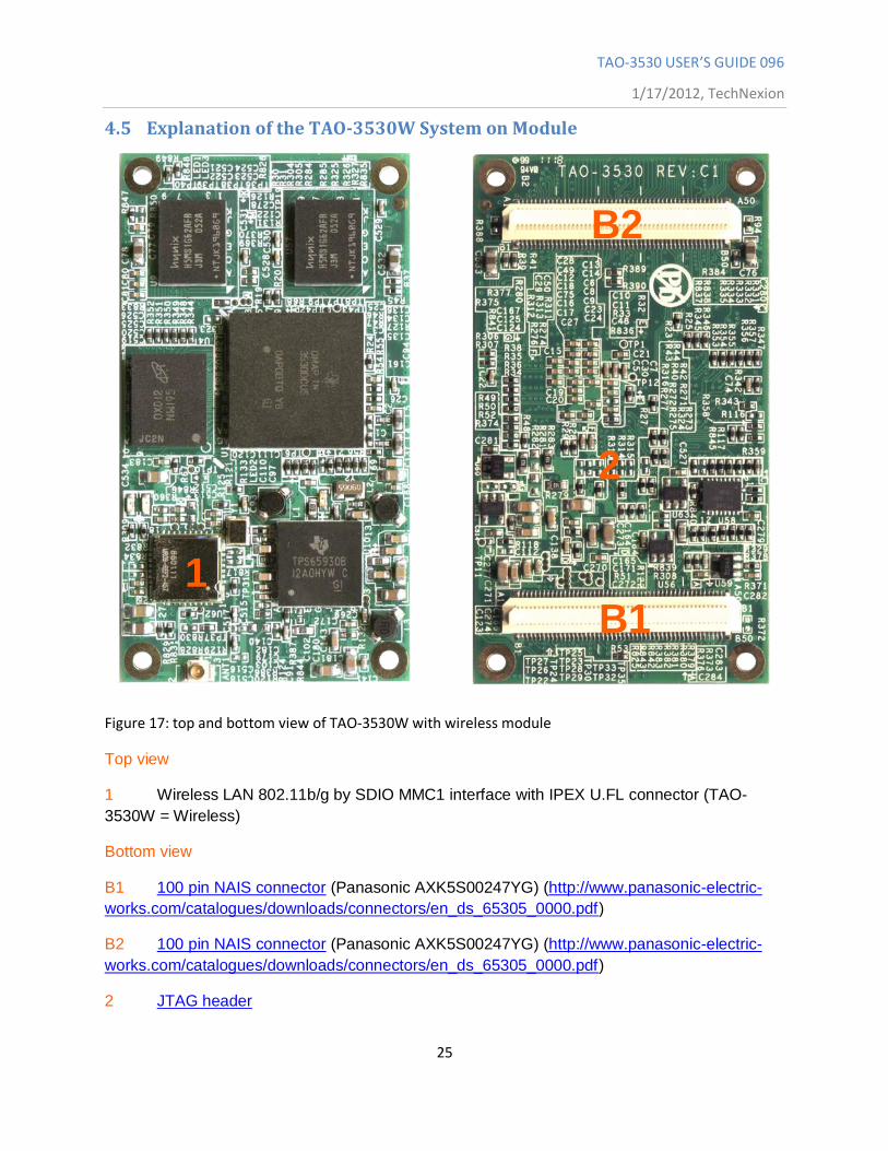
4.5 Explanation of the TAO-3530W System on Module
Figure 17: top and bottom view of TAO-3530W with wireless module
Top view
1 Wireless LAN 802.11b/g by SDIO MMC1 interface with IPEX U.FL connector (TAO-
3530W = Wireless)
Bottom view
B1 100 pin NAIS connector (Panasonic AXK5S00247YG) (http://www.panasonic-electric-
works.com/catalogues/downloads/connectors/en_ds_65305_0000.pdf)
B2 100 pin NAIS connector (Panasonic AXK5S00247YG) (http://www.panasonic-electric-
works.com/catalogues/downloads/connectors/en_ds_65305_0000.pdf)
2 JTAG header
B2
B1 1
2
TAO-3530 USER’S GUIDE 096
1/17/2012, TechNexion
26
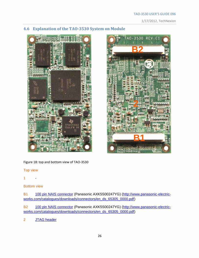
4.6 Explanation of the TAO-3530 System on Module
Figure 18: top and bottom view of TAO-3530
Top view
1 -
Bottom view
B1 100 pin NAIS connector (Panasonic AXK5S00247YG) (http://www.panasonic-electric-
works.com/catalogues/downloads/connectors/en_ds_65305_0000.pdf)
B2 100 pin NAIS connector (Panasonic AXK5S00247YG) (http://www.panasonic-electric-
works.com/catalogues/downloads/connectors/en_ds_65305_0000.pdf)
2 JTAG header
B2
B1
2
TAO-3530 USER’S GUIDE 096
1/17/2012, TechNexion
27
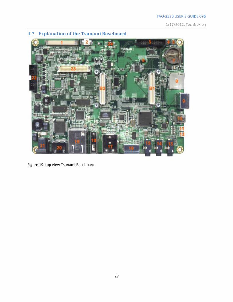
4.7 Explanation of the Tsunami Baseboard
Figure 19: top view Tsunami Baseboard
TAO-3530 USER’S GUIDE 096
1/17/2012, TechNexion
28
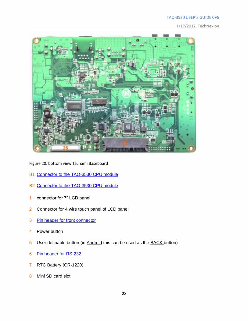
Figure 20: bottom view Tsunami Baseboard
B1 Connector to the TAO-3530 CPU module
B2 Connector to the TAO-3530 CPU module
1 connector for 7” LCD panel
2 Connector for 4 wire touch panel of LCD panel
3 Pin header for front connector
4 Power button
5 User definable button (in Android this can be used as the BACK button)
6 Pin header for RS-232
7 RTC Battery (CR-1220)
8 Mini SD card slot
TAO-3530 USER’S GUIDE 096
1/17/2012, TechNexion
29
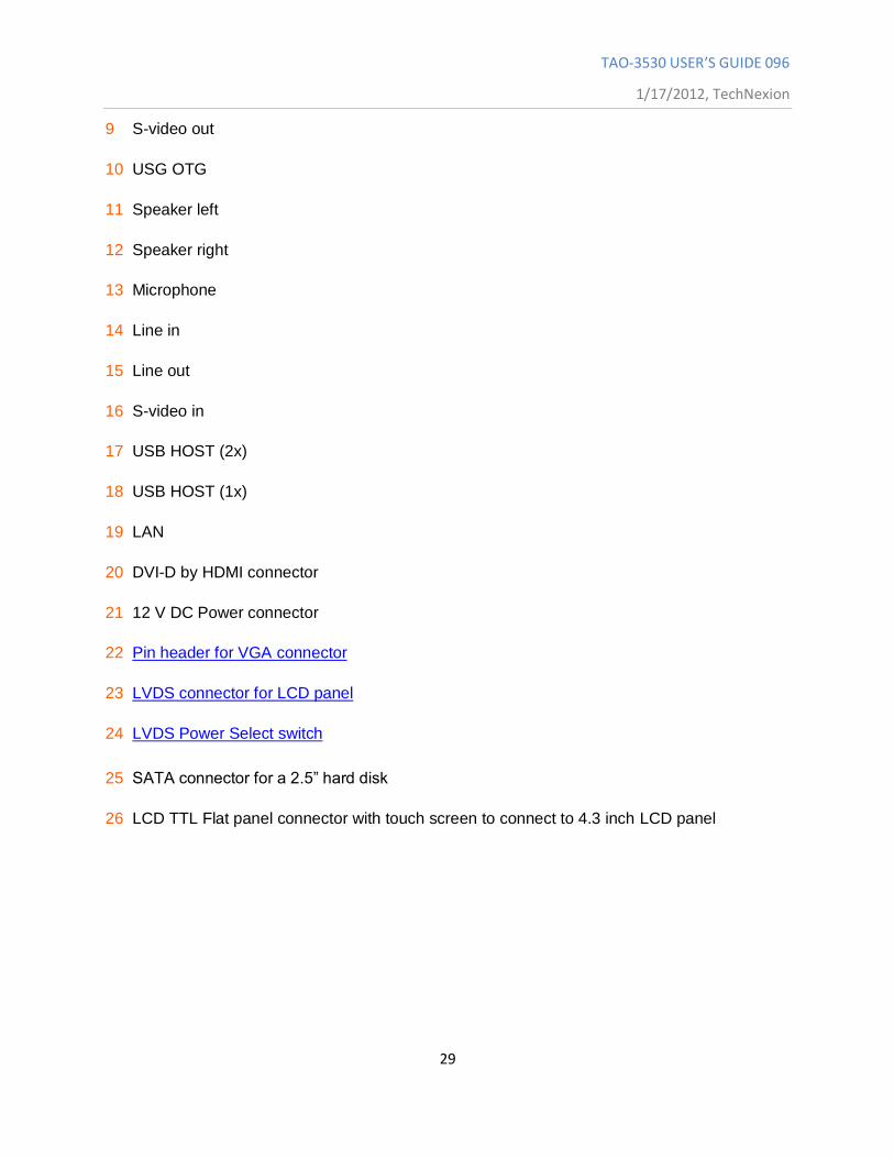
9 S-video out
10 USG OTG
11 Speaker left
12 Speaker right
13 Microphone
14 Line in
15 Line out
16 S-video in
17 USB HOST (2x)
18 USB HOST (1x)
19 LAN
20 DVI-D by HDMI connector
21 12 V DC Power connector
22 Pin header for VGA connector
23 LVDS connector for LCD panel
24 LVDS Power Select switch
25 SATA connector for a 2.5” hard disk
26 LCD TTL Flat panel connector with touch screen to connect to 4.3 inch LCD panel
TAO-3530 USER’S GUIDE 096
1/17/2012, TechNexion
30
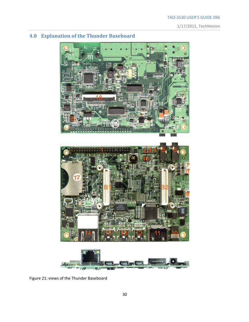
4.8 Explanation of the Thunder Baseboard
Figure 21: views of the Thunder Baseboard
TAO-3530 USER’S GUIDE 096
1/17/2012, TechNexion
31
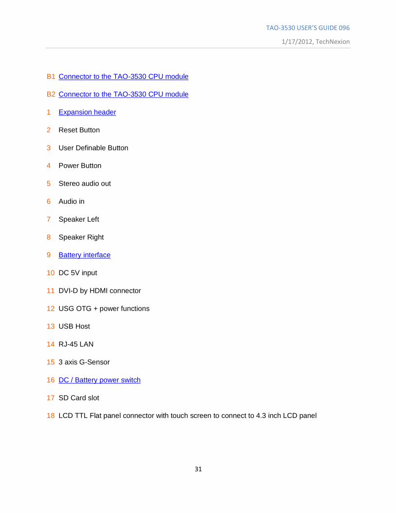
B1 Connector to the TAO-3530 CPU module
B2 Connector to the TAO-3530 CPU module
1 Expansion header
2 Reset Button
3 User Definable Button
4 Power Button
5 Stereo audio out
6 Audio in
7 Speaker Left
8 Speaker Right
9 Battery interface
10 DC 5V input
11 DVI-D by HDMI connector
12 USG OTG + power functions
13 USB Host
14 RJ-45 LAN
15 3 axis G-Sensor
16 DC / Battery power switch
17 SD Card slot
18 LCD TTL Flat panel connector with touch screen to connect to 4.3 inch LCD panel
TAO-3530 USER’S GUIDE 096
1/17/2012, TechNexion
32
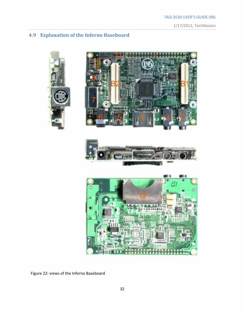
4.9 Explanation of the Inferno Baseboard
Figure 22: views of the Inferno Baseboard
TAO-3530 USER’S GUIDE 096
1/17/2012, TechNexion
33
B1 Connector to the TAO-3530 CPU module
B2 Connector to the TAO-3530 CPU module
1 Expansion header
2 Audio in
3 Stereo audio out
4 DVI-D by HDMI connector
5 USB OTG + power functions
6 DC 5V input
7 S-Video
8 USB Host
9 User Definable button
10 Reset button
11 Pin header for RS-232
12 SD Card slot
TAO-3530 USER’S GUIDE 096
1/17/2012, TechNexion
34
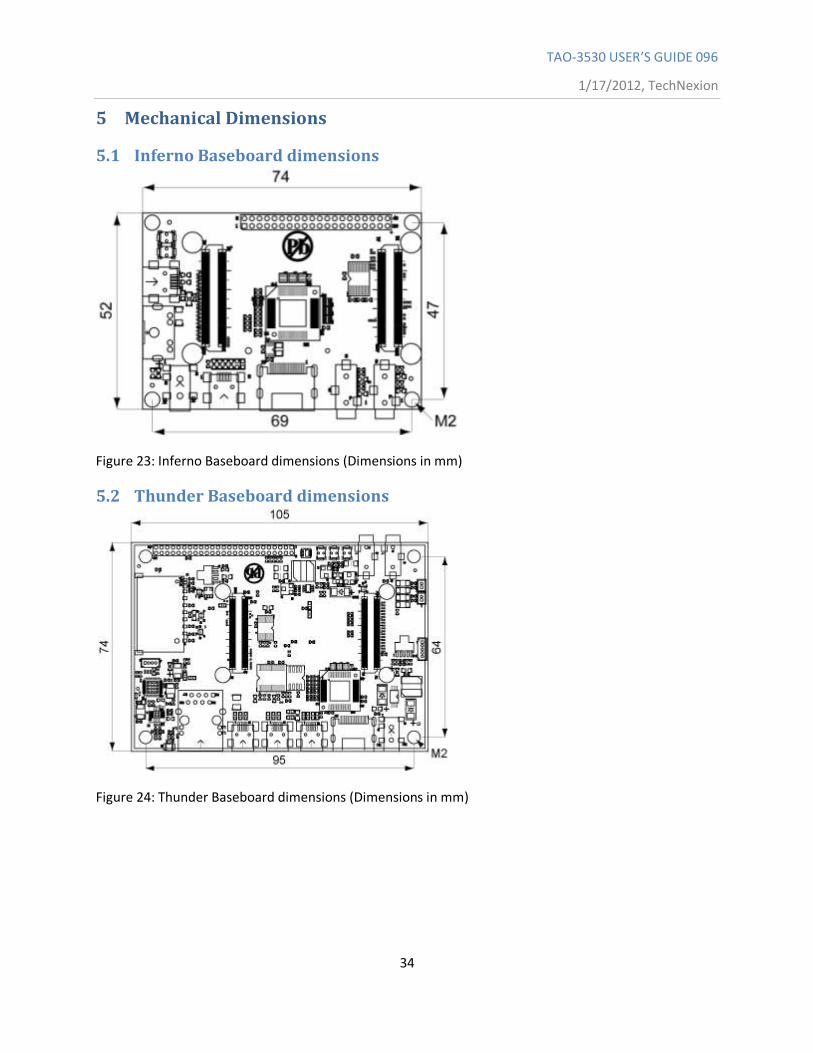
5 Mechanical Dimensions
5.1 Inferno Baseboard dimensions
Figure 23: Inferno Baseboard dimensions (Dimensions in mm)
5.2 Thunder Baseboard dimensions
Figure 24: Thunder Baseboard dimensions (Dimensions in mm)
TAO-3530 USER’S GUIDE 096
1/17/2012, TechNexion
35
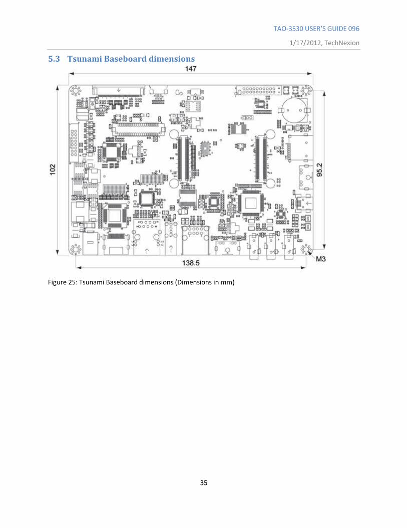
5.3 Tsunami Baseboard dimensions
Figure 25: Tsunami Baseboard dimensions (Dimensions in mm)
TAO-3530 USER’S GUIDE 096
1/17/2012, TechNexion
36
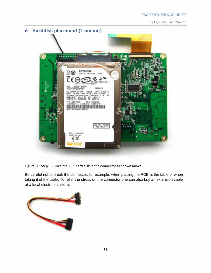
6 Harddisk placement (Tsunami)
Figure 26: Step1 – Place the 2.5” hard disk in the connector as shown above.
Be careful not to break the connector, for example, when placing the PCB at the table or when
taking it of the table. To relief the stress on the connector one can also buy an extension cable
at a local electronics store.
TAO-3530 USER’S GUIDE 096
1/17/2012, TechNexion
37
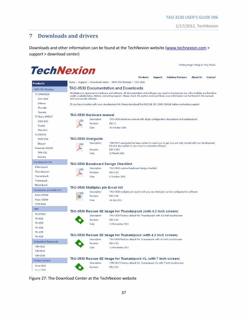
7 Downloads and drivers
Downloads and other information can be found at the TechNexion website (www.technexion.com >
support > download center)
Figure 27: The Download Center at the TechNexion website
TAO-3530 USER’S GUIDE 096
1/17/2012, TechNexion
38
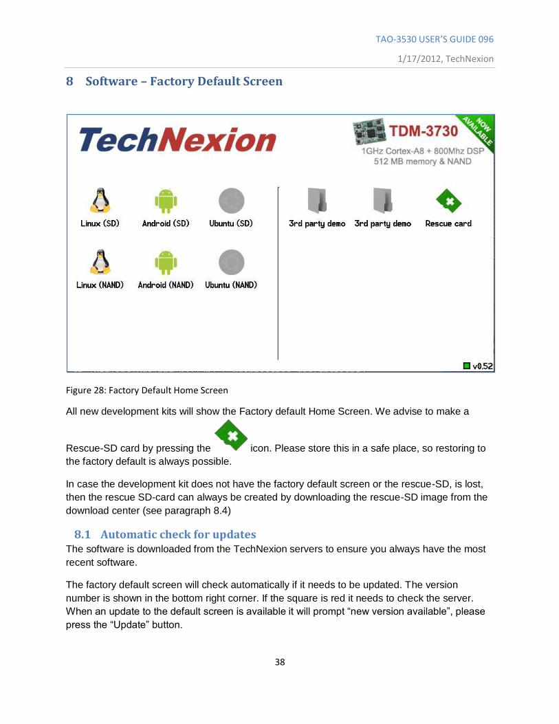
8 Software – Factory Default Screen
Figure 28: Factory Default Home Screen
All new development kits will show the Factory default Home Screen. We advise to make a
Rescue-SD card by pressing the icon. Please store this in a safe place, so restoring to
the factory default is always possible.
In case the development kit does not have the factory default screen or the rescue-SD, is lost,
then the rescue SD-card can always be created by downloading the rescue-SD image from the
download center (see paragraph 8.4)
8.1 Automatic check for updates The software is downloaded from the TechNexion servers to ensure you always have the most
recent software.
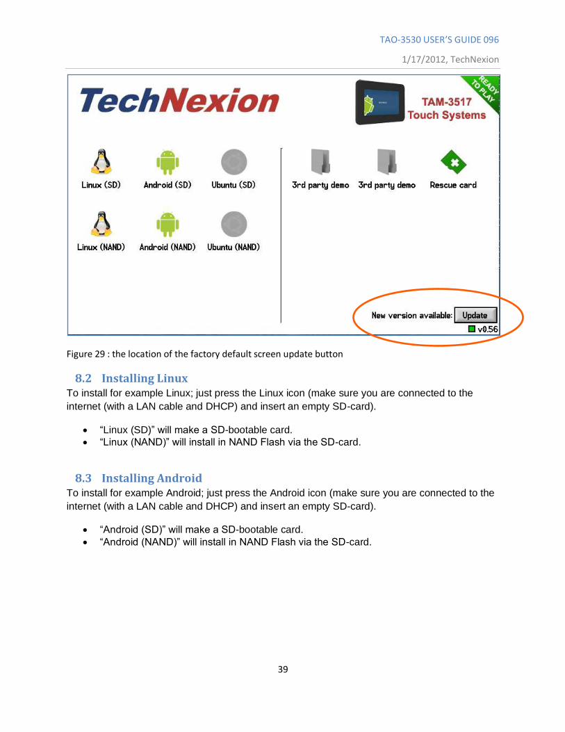
The factory default screen will check automatically if it needs to be updated. The version
number is shown in the bottom right corner. If the square is red it needs to check the server.
When an update to the default screen is available it will prompt “new version available”, please
press the “Update” button.
TAO-3530 USER’S GUIDE 096
1/17/2012, TechNexion
39
Figure 29 : the location of the factory default screen update button
8.2 Installing Linux To install for example Linux; just press the Linux icon (make sure you are connected to the
internet (with a LAN cable and DHCP) and insert an empty SD-card).
“Linux (SD)” will make a SD-bootable card.
“Linux (NAND)” will install in NAND Flash via the SD-card.
8.3 Installing Android To install for example Android; just press the Android icon (make sure you are connected to the
internet (with a LAN cable and DHCP) and insert an empty SD-card).
“Android (SD)” will make a SD-bootable card.
“Android (NAND)” will install in NAND Flash via the SD-card.
TAO-3530 USER’S GUIDE 096
1/17/2012, TechNexion
40
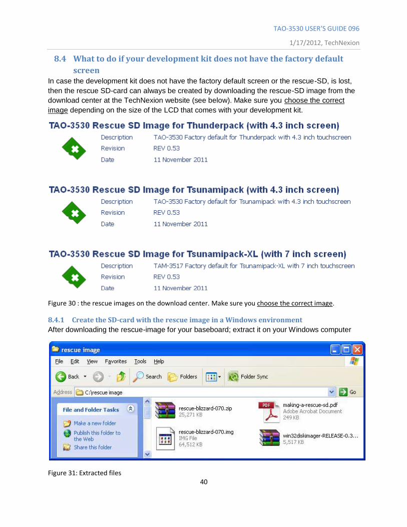
8.4 What to do if your development kit does not have the factory default
screen In case the development kit does not have the factory default screen or the rescue-SD, is lost,
then the rescue SD-card can always be created by downloading the rescue-SD image from the
download center at the TechNexion website (see below). Make sure you choose the correct
image depending on the size of the LCD that comes with your development kit.
Figure 30 : the rescue images on the download center. Make sure you choose the correct image.
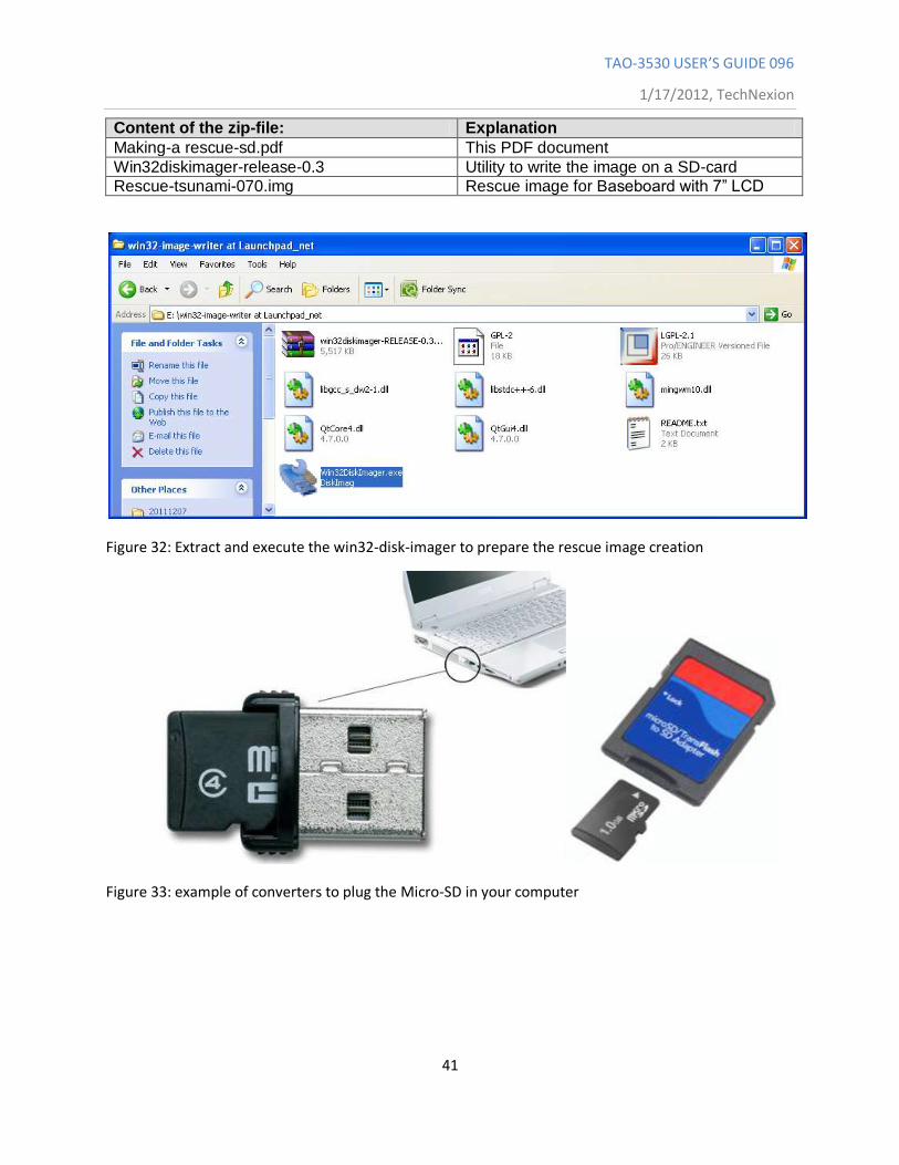
8.4.1 Create the SD-card with the rescue image in a Windows environment
After downloading the rescue-image for your baseboard; extract it on your Windows computer
Figure 31: Extracted files
TAO-3530 USER’S GUIDE 096
1/17/2012, TechNexion
41
Content of the zip-file: Explanation
Making-a rescue-sd.pdf This PDF document
Win32diskimager-release-0.3 Utility to write the image on a SD-card
Rescue-tsunami-070.img Rescue image for Baseboard with 7” LCD
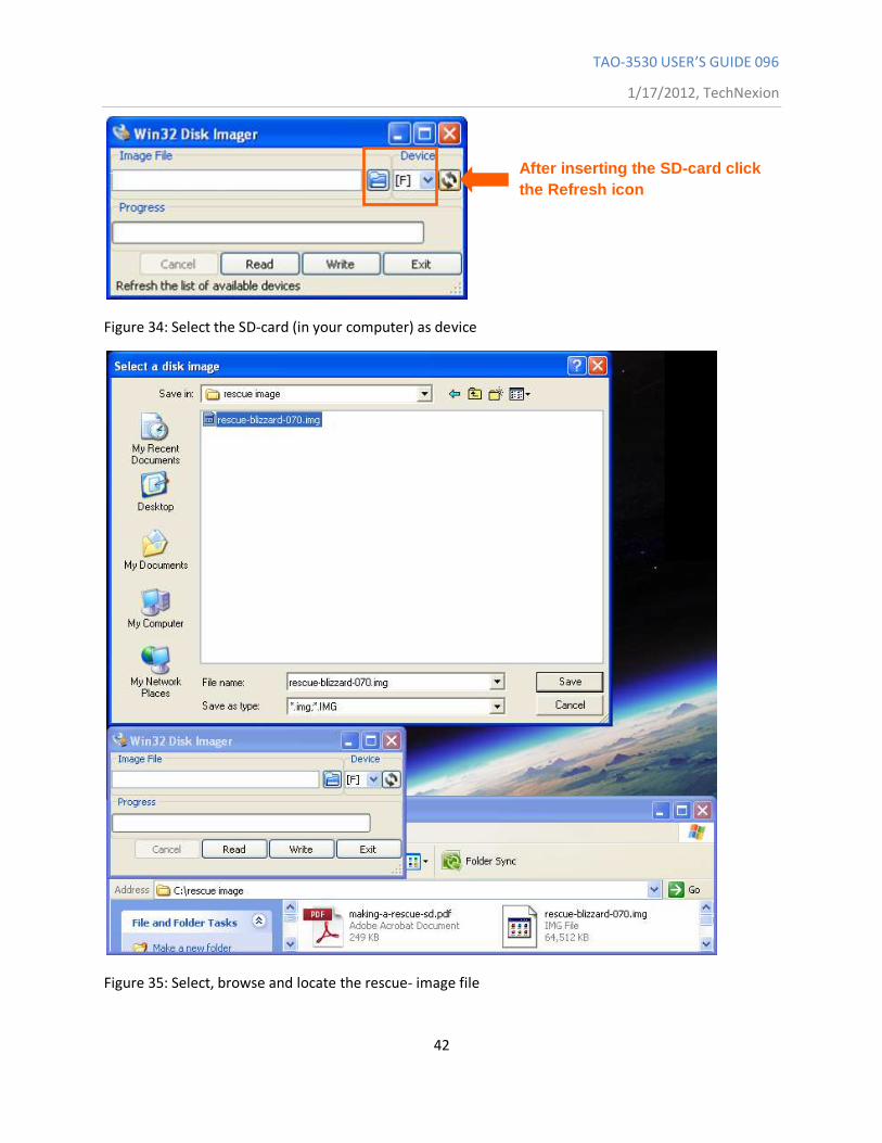
Figure 32: Extract and execute the win32-disk-imager to prepare the rescue image creation
Figure 33: example of converters to plug the Micro-SD in your computer
TAO-3530 USER’S GUIDE 096
1/17/2012, TechNexion
42
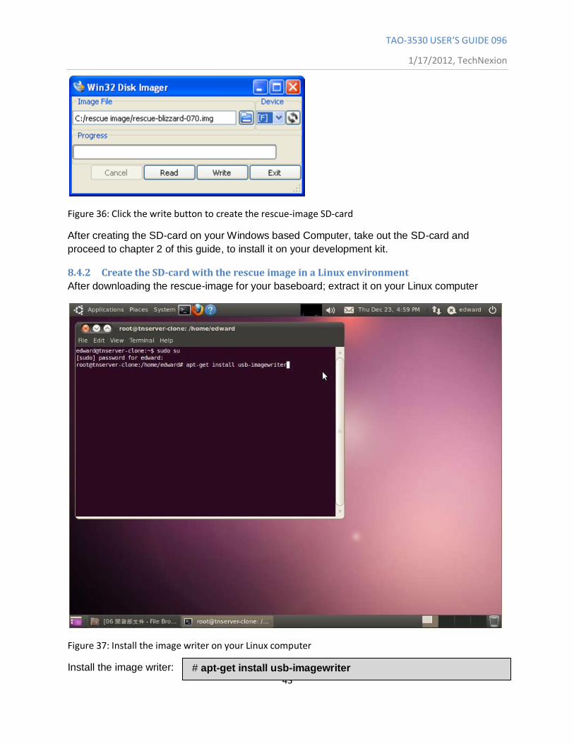
Figure 34: Select the SD-card (in your computer) as device
Figure 35: Select, browse and locate the rescue- image file
After inserting the SD-card click
the Refresh icon
TAO-3530 USER’S GUIDE 096
1/17/2012, TechNexion
43
Figure 36: Click the write button to create the rescue-image SD-card
After creating the SD-card on your Windows based Computer, take out the SD-card and
proceed to chapter 2 of this guide, to install it on your development kit.
8.4.2 Create the SD-card with the rescue image in a Linux environment
After downloading the rescue-image for your baseboard; extract it on your Linux computer
Figure 37: Install the image writer on your Linux computer
Install the image writer: # apt-get install usb-imagewriter
TAO-3530 USER’S GUIDE 096
1/17/2012, TechNexion
44
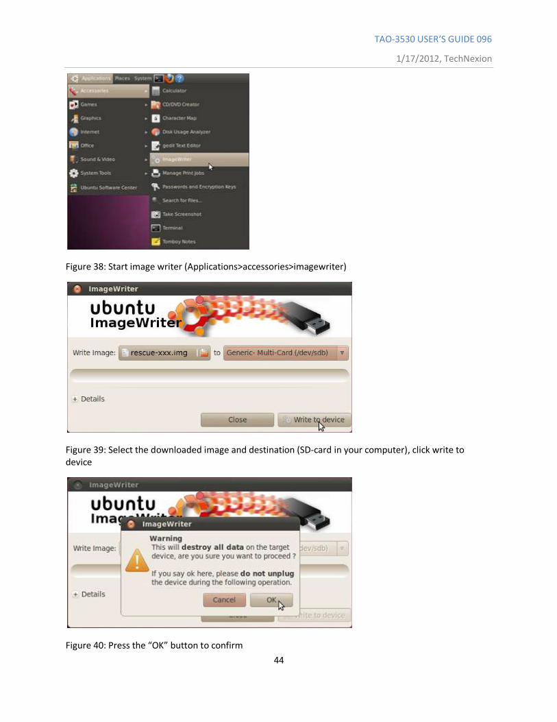
Figure 38: Start image writer (Applications>accessories>imagewriter)
Figure 39: Select the downloaded image and destination (SD-card in your computer), click write to device
Figure 40: Press the “OK” button to confirm
TAO-3530 USER’S GUIDE 096
1/17/2012, TechNexion
45
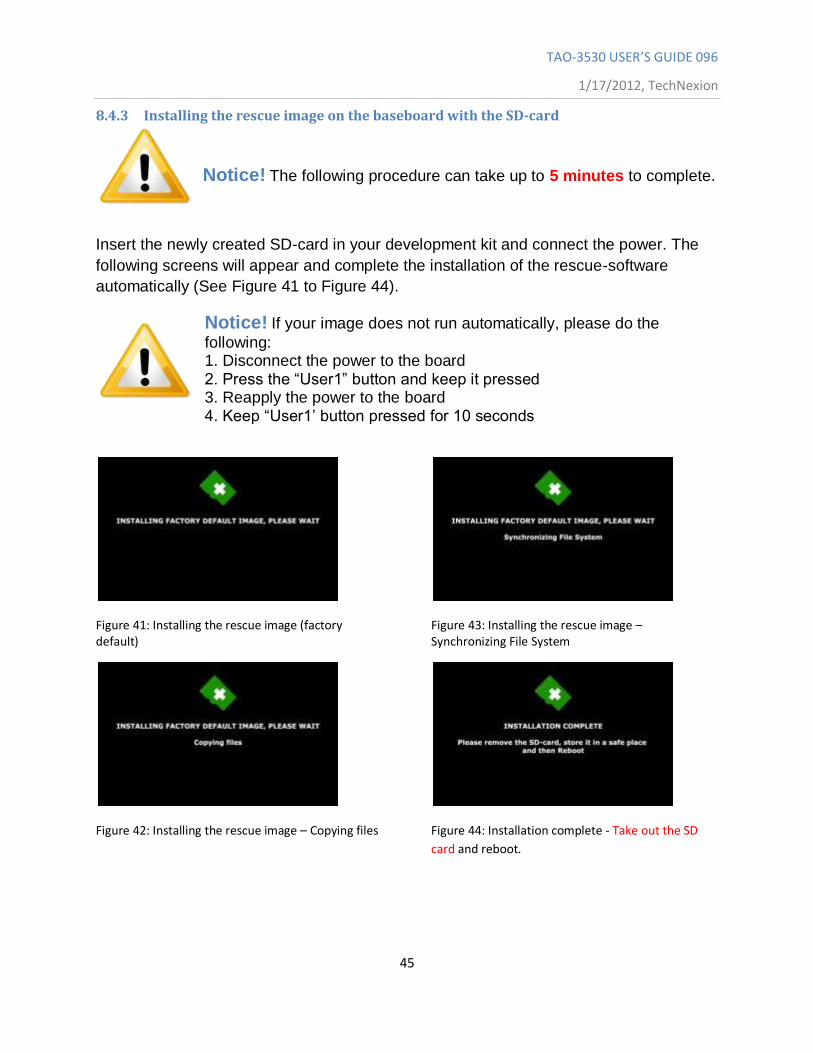
8.4.3 Installing the rescue image on the baseboard with the SD-card
Notice! The following procedure can take up to 5 minutes to complete.
Insert the newly created SD-card in your development kit and connect the power. The
following screens will appear and complete the installation of the rescue-software
automatically (See Figure 41 to Figure 44).
Notice! If your image does not run automatically, please do the
following: 1. Disconnect the power to the board 2. Press the “User1” button and keep it pressed 3. Reapply the power to the board 4. Keep “User1‟ button pressed for 10 seconds
Figure 41: Installing the rescue image (factory default)
Figure 42: Installing the rescue image – Copying files
Figure 43: Installing the rescue image – Synchronizing File System
Figure 44: Installation complete - Take out the SD
card and reboot.
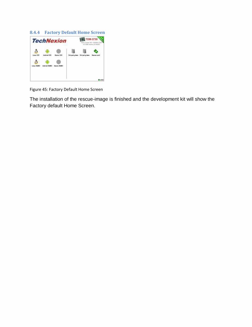
8.4.4 Factory Default Home Screen
Figure 45: Factory Default Home Screen
The installation of the rescue-image is finished and the development kit will show the
Factory default Home Screen.
TAO-3530 USER’S GUIDE 096
1/17/2012, TechNexion
47
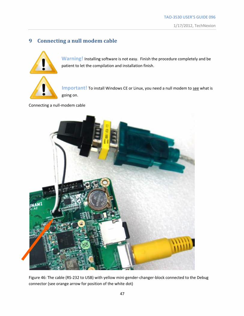
9 Connecting a null modem cable
Warning! Installing software is not easy. Finish the procedure completely and be
patient to let the compilation and installation finish.
Important! To install Windows CE or Linux, you need a null modem to see what is
going on.
Connecting a null-modem cable
Figure 46: The cable (RS-232 to USB) with yellow mini-gender-changer-block connected to the Debug
connector (see orange arrow for position of the white dot)

TAO-3530 USER’S GUIDE 096
1/17/2012, TechNexion
48
Figure 47: The cable (RS-232 to USB) with null-modem-block connected to the debug connector (see
orange arrow for position of the white dot (note: turned 180 degrees))
Start PuTTY on your computer and make sure the “Options controlling local serial lines” are as Figure 48:
Figure 48: Settings
TAO-3530 USER’S GUIDE 096
1/17/2012, TechNexion
49
For computers running a Windows Operating System more steps (see Figure 49 to Figure 51) might be
required in order to check which serial line is used (see orange circle in Figure 48):
Figure 49: Right click on “My Computer” and select Properties
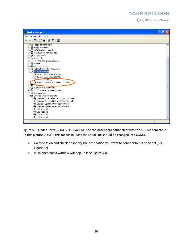
Figure 50: Go to the hardware tab and select “Device manager”
TAO-3530 USER’S GUIDE 096
1/17/2012, TechNexion
50
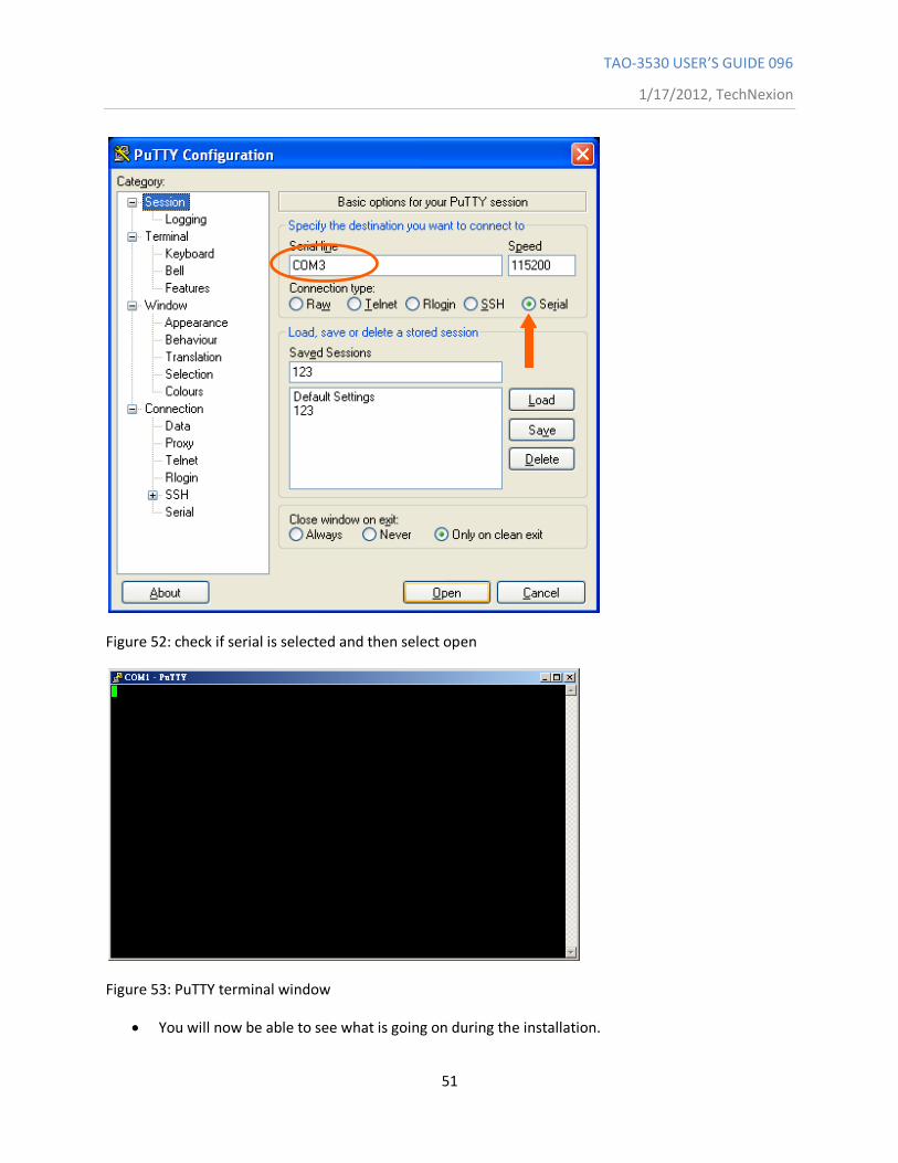
Figure 51: Under Ports (COM & LPT) you will see the baseboard connected with the null modem cable
(in this picture COM3), this means in Putty the serial line should be changed into COM3.
Go to Session and check if “specify the destination you want to connect to “ is on Serial (See
Figure 52)
Push open and a window will pop up (see Figure 53)
TAO-3530 USER’S GUIDE 096
1/17/2012, TechNexion
51
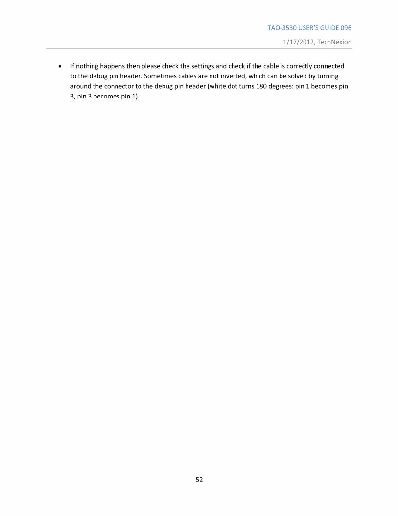
Figure 52: check if serial is selected and then select open
Figure 53: PuTTY terminal window
You will now be able to see what is going on during the installation.
TAO-3530 USER’S GUIDE 096
1/17/2012, TechNexion
52
If nothing happens then please check the settings and check if the cable is correctly connected
to the debug pin header. Sometimes cables are not inverted, which can be solved by turning
around the connector to the debug pin header (white dot turns 180 degrees: pin 1 becomes pin
3, pin 3 becomes pin 1).
TAO-3530 USER’S GUIDE 096
1/17/2012, TechNexion
53
10 Software – Linux
10.1 Introduction This Chapter explains how to use Linux and will mostly use a null modem and terminal to issue
commands to the board. Technical Software knowledge is required.
For much easier installation of Linux please read the “factory default screen” chapter
Things to know in advance:
We use Code Sourcery G++ 2010.09-50 (gcc 4.5.1)
Remember to use cross compile versions of all bintools:
export CC=arm-none-linux-gnueabi-gcc
export AS=arm-none-linux-gnueabi-as
export CPP=arm-none-linux-gnueabi-cpp
etc.
It is recommended to use a PC with a Linux environment (for example: Ubuntu, Fedora)
U-boot#: Refers to commands executed under U-boot
devkit#: Refers to commands executed under TAO-3530 Linux
Host#: Refers to commands executed at PC
10.1 Quick install guide for installing a cross-compiler. 1. Choose your cross compiler.
TechNexion engineering uses CodeSourcery C++ Lite 2010.09-50:
https://sourcery.mentor.com/sgpp/lite/arm/portal/release1600
Other versions can work too: CodeSourcery C++ Lite 2009q1 is a popular version in the community.
2. Once installed, add the bin folder of the toolchain to your PATH
If your toolchain is installed in /opt/arm-2010.09, you should add /opt/arm-2010.09/bin/ to PATH
i.e:
PATH=/usr/bin:/bin:/opt/arm-2010.09/bin:.
TAO-3530 USER’S GUIDE 096
1/17/2012, TechNexion
54
Note: check that you added the right bin folder: do not add '/opt/arm-2010.09/arm-none-linux-
gnueabi/bin/' !
3. Set your CROSS_COMPILE variable to the ABI prefix:
CROSS_COMPILE=arm-none-linux-gnueabi-
(or 'CROSS_COMPILE=ccache arm-none-linux-gnueabi' if ccache is used)
4. Set the architecture variable to arm: ARCH=arm
Both ARCH and CROSS_COMPILE can be set compile time, but it is often easier to set them once in the
working shell.
10.2 XUKR build instructions (From the XUKR-20120103 for TDM3730, TAO3530 and TAM3517 Release candidate) This file contains build reference for x-loader, u-boot and kernel, and a sample Angstrom Linux root file system / userland. It is assumed a cross-compiling environment is already set up. Prebuilt binaries can be found in the prebuilt/ folder.
10.2.1 X-loader
For TAO-3530 based boards, compile using: % make distclean && make tao3530_config && make -j 2 Similarly, for TDM-3730 based boards, the command is: % make distclean && make tdm3730_config && make -j 2 And for TAM-3517 based boards, the command is: % make distclean && make tam3517_config && make -j 2 The resulting binary is named MLO.
TAO-3530 USER’S GUIDE 096
1/17/2012, TechNexion
55
10.2.2 U-boot
To set display size, you need to (unfortunately) edit the relevant configuration file. For 4.3" panel, set the define #define TN_PANEL 043 in include/configs/tao3530.h (For tao3530 - for tdm3730 the file is named tdm3730.h etc) Similarly, for 7" LCD the variable is to be set to #define TN_PANEL 070 instead. For TAO-3530 based boards: % make distclean && make tao3530_config && make -j 2 tao3530 For TDM-3730 based boards: % make distclean && make tdm3730_config && make -j 2 tdm3730 For TAM-3517 based boards: % make distclean && make tam3517_config && make -j 2 tam3517 The resulting binary is named u-boot.bin For THB based boards the SW3 switch define must be enabled for LCD "detection" to work.
10.2.3 Kernel
The kernel configuration depends on both CPU module, baseboard and display. For TAO-3530 on a Tsunami baseboard: % make distclean && make tao3530_tsunami_defconfig && make -j 2 uImage && make modules For TAO-3530 on a Thunder baseboard: % make distclean && make tao3530_thunder_defconfig && make -j 2 uImage && make modules For TDM-3730 on a Blizzard baseboard: % make distclean && make tdm3730_blizzard_defconfig && make -j 2 uImage && make modules
TAO-3530 USER’S GUIDE 096
1/17/2012, TechNexion
56
For TAM-3517 on a Twister baseboard: % make distclean && make tam3517_twister_defconfig && make -j 2 uImage && make modules For TAM-3517 on a THB baseboard: % make distclean && make tam3517_thb_defconfig && make -j 2 uImage && make modules The resulting kernel binary is arch/arm/boot/uImage
10.2.4 Root filesystem
The root filesystem is based on the Angstrom-distribution. There are two things to keep in mind before booting with this: 1. For TAO-3530 the default console is ttyO2 and not ttyO0 – change this in /etc/inittab 2. The wireless kernel module, and the PowerVR modules need to be placed in the /boot folder of the root filesystem.
10.3 Compiling for TAO-3530
While strictly not necessary; the following steps are for getting the most out of your DM3730
Enable floating point using the Neon SIMD DPS by:
-mfpu=neon -funsafe-math-optimizations -mfloat-abi=softfp
The switch enabling unsafe floating point should be used with care, however it is necessary for gcc to
generate Neon instructions (Neon is not 100% compatible with IEEE standards)
Soft-fp ABI switch is to enable FP instructions, but use software emulated fp calling conventions.
The TAO-3530 contains an ARM Cortex A8 core, which supports ARMv7-A instructions
-marm -mcpu=cortex-a8 -march=armv7-a

TAO-3530 USER’S GUIDE 096
1/17/2012, TechNexion
57
Misc flags:
-ftree-vectorize
is not included in -O2, and allows gcc to auto-generate SIMD code for Neon
All-in-all:
arm-none-linux-gnueabi-gcc -marm -mcpu=cortex-a8 -march=armv7-a -mfpu=neon -funsafe-math-
optimizations -ftree-vectorize -mfloat-abi=softfp
or:
setenv ARMROOT /usr/src/tmp/tam3517-default/rootfs/usr
setenv CC arm-none-linux-gnueabi-gcc
setenv AS arm-none-linux-gnueabi-as
setenv CPP arm-none-linux-gnueabi-cpp
setenv CFLAGS "-O2 -fwhole-program -marm -mcpu=cortex-a8 -march=armv7-a -mfpu=neon -funsafe-
math-optimizations -ftree-vectorize -mfloat-abi=softfp -I${ARMROOT}/include -L${ARMROOT}/lib"
configure --prefix=$ARMROOT --host=i686 --target=arm
10.3.1 QT
QT libraries come precompiled in the Ångström root file system provided.
10.4 Basic components of a bootable Linux SD card: - Boot partition (a FAT 32 LBA partition) containing
X-loader, binary (MLO)
TAO-3530 USER’S GUIDE 096
1/17/2012, TechNexion
58
u-boot, boot loader
uImage, Linux kernel
- A root file system (a Linux file system, like ext3).
To prepare a bootable SD card, one needs to:
1. Partition the SD card into two partitions (FAT and, say EXT3)
2. Format the partitions
3. Copy the boot files to the FAT partition
4. Copy the rootfs files to the EXT3 partition
Note1: copying the rootfs must often be done as root, to preserve ownership and permissions of
files.
Note2: if you want your SD card to be bootable no matter what, it must contain a special
boot/partition signature. In this case we recommend you to reuse the partition table from one of
TechNexion's Angstrom SD card images, and if needed resize the EXT3 partition.
(Do NOT use the rescue card image bootsector, it is special and not for general purpose)
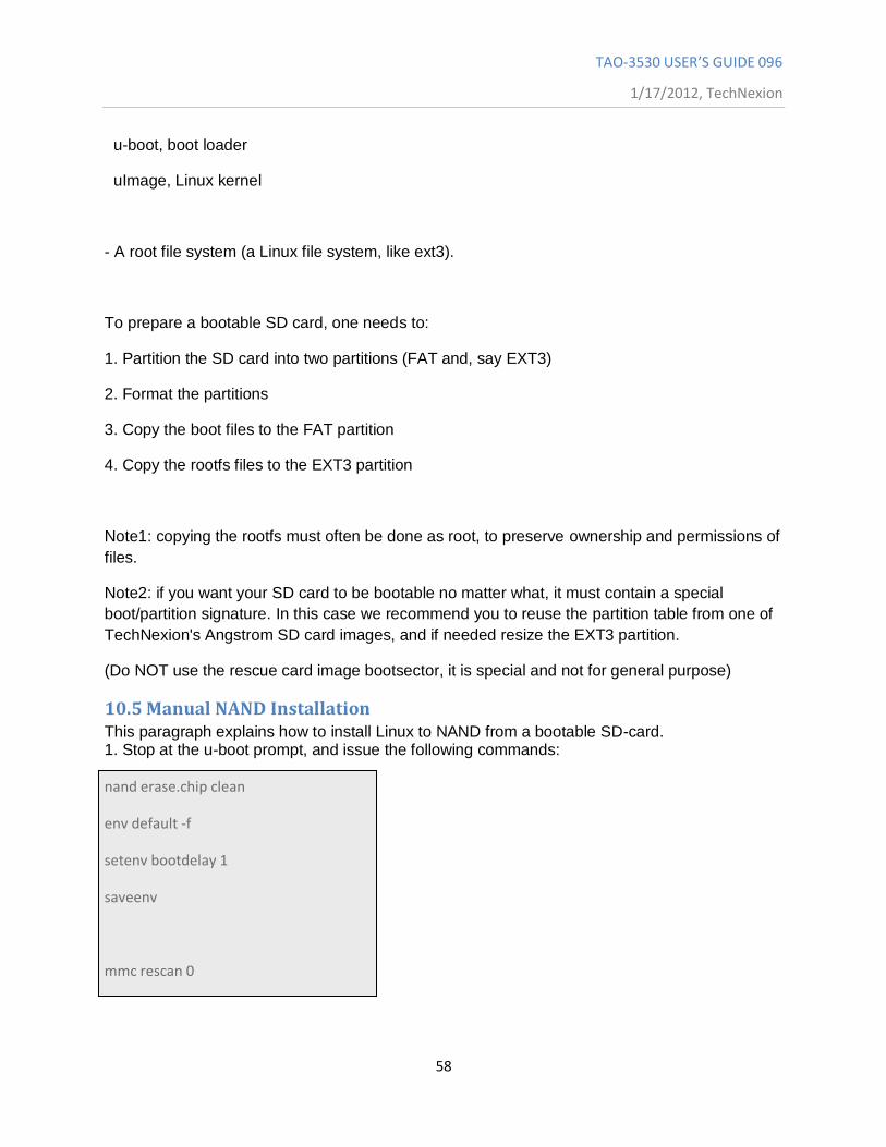
10.5 Manual NAND Installation This paragraph explains how to install Linux to NAND from a bootable SD-card. 1. Stop at the u-boot prompt, and issue the following commands:
nand erase.chip clean
env default -f
setenv bootdelay 1
saveenv
mmc rescan 0
TAO-3530 USER’S GUIDE 096
1/17/2012, TechNexion
59
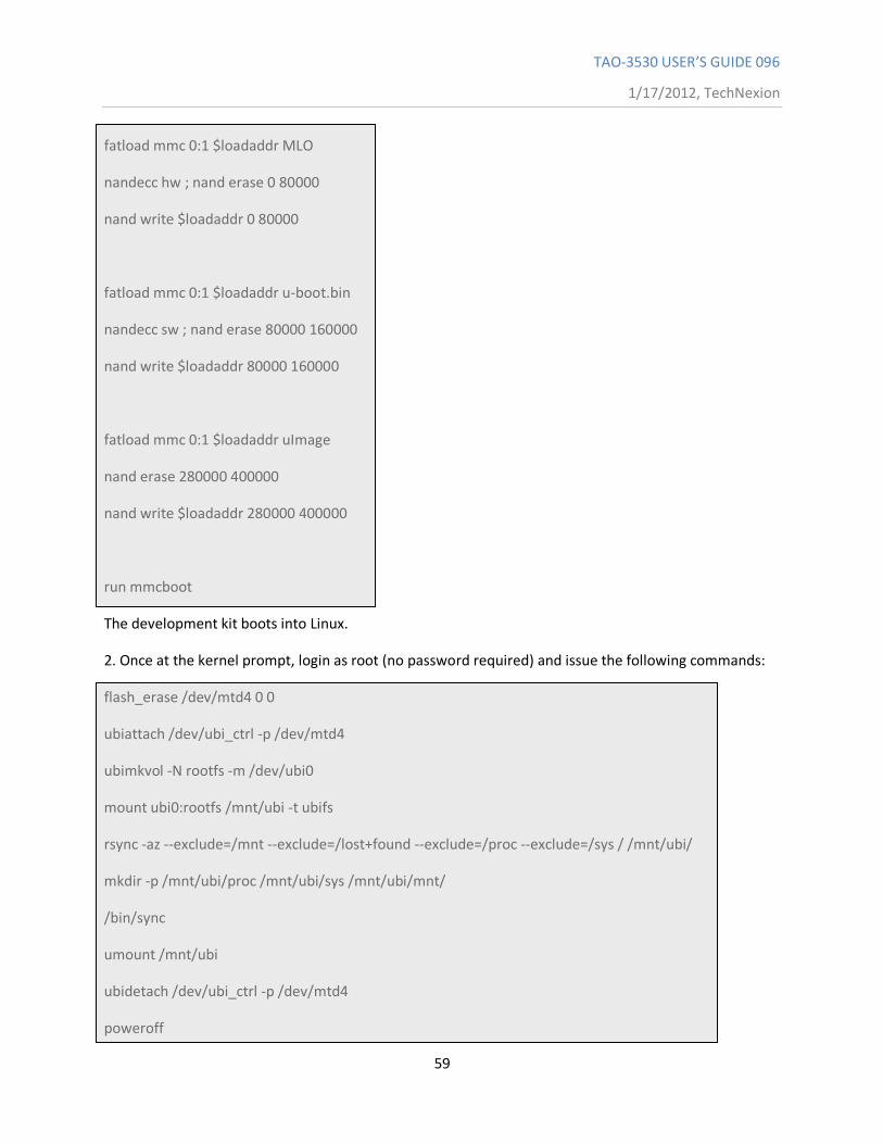
fatload mmc 0:1 $loadaddr MLO
nandecc hw ; nand erase 0 80000
nand write $loadaddr 0 80000
fatload mmc 0:1 $loadaddr u-boot.bin
nandecc sw ; nand erase 80000 160000
nand write $loadaddr 80000 160000
fatload mmc 0:1 $loadaddr uImage
nand erase 280000 400000
nand write $loadaddr 280000 400000
run mmcboot
The development kit boots into Linux.
2. Once at the kernel prompt, login as root (no password required) and issue the following commands:
flash_erase /dev/mtd4 0 0
ubiattach /dev/ubi_ctrl -p /dev/mtd4
ubimkvol -N rootfs -m /dev/ubi0
mount ubi0:rootfs /mnt/ubi -t ubifs
rsync -az --exclude=/mnt --exclude=/lost+found --exclude=/proc --exclude=/sys / /mnt/ubi/
mkdir -p /mnt/ubi/proc /mnt/ubi/sys /mnt/ubi/mnt/
/bin/sync
umount /mnt/ubi
ubidetach /dev/ubi_ctrl -p /dev/mtd4
poweroff
TAO-3530 USER’S GUIDE 096
1/17/2012, TechNexion
60
10.6 How to
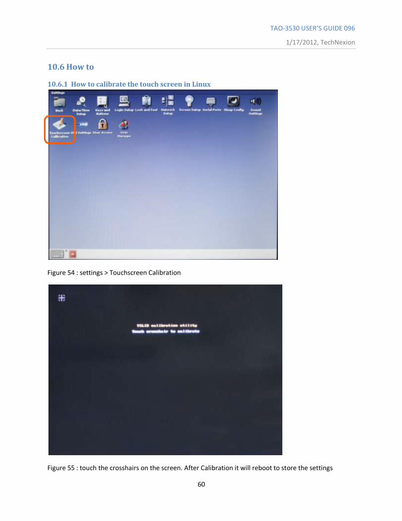
10.6.1 How to calibrate the touch screen in Linux
Figure 54 : settings > Touchscreen Calibration
Figure 55 : touch the crosshairs on the screen. After Calibration it will reboot to store the settings
TAO-3530 USER’S GUIDE 096
1/17/2012, TechNexion
61
In case the calibration is incorrect, you have two options to initiate the calibration process
10.6.1.1 Recover the touch calibration with a USB keyboard.
1. Plug in the USB keyboard
2. Press Ctrl+Alt+F1 (the terminal-screen will open)
3. Type "root" and press return
4. Type "ts_calibrate" and press return
5. Calibrate the screen
6. Type "reboot" and press return
10.6.1.2 Recover the touch calibration with a USB mouse
1. Power off the unit
2. Insert a USB mouse
3. Click on “settings” and then “tocuhscreen calibration”
4. Calibrate by using the mouse to click on the crosshairs
5. The unit will reboot
10.6.2 How to use OPKG
First connect your development kit to the internet. Then, use
opkg update (to update the repository locations etc.)
Then use
opkg list-installed (to list the installed packages)
opkg list (to list the available packages (use grep! the list is long))
opkg install <package> (to install <package>)
opkg remove <package> (to uninstall a package.)
A few more useful commands:
opkg search <full/path/filename> (tells you which package provides the named file)
TAO-3530 USER’S GUIDE 096
1/17/2012, TechNexion
62
10.6.3 How to enable wireless
Wireless can be enabled using a terminal in the following two ways.
10.6.3.1 The easy way
1. Open a terminal
2. # wireless.sh
3. You will be shown a list of networks in range, and asked to type in the name of the network
4. Once an existing network has been typed in, you will be asked for a passphrase (if you are prompted
for the net name again, it means you mistyped something)
Note: it can be enough to type in a part of the network name -- if that part is not a part in any other
nearby network SSID
5. After these steps, the system tries to connect to the network
10.6.3.2 If the easy way does not work
In case the above does not work (due to different network settings etc), you can use the command line
tools to connect manually:
1. Use 'insmod /boot/libertas_sdio.ko' to load the wireless driver
2. Use 'ifconfig wlan0 up' to enable the wireless interface
3. Use 'iwlist wlan0 scan', to scan the networks
4. Use 'wpa_passphrase' to generate the WPA psk for an SSID
5. Edit a wpa_supplicant configuration file containing your network settings
6. Use 'wpa_supplicant -Dnl80211 -iwlan0 -c file' to connect to the SSID in file
7. Use 'udhcpc -i wlan0' to request and IP adress, gateway and DNS server
10.6.3.3 Common errors
Problem: you see the error message "assoc: bss (null) not in scan results"
Reason: Wireless chip sees no networks
Solution1: Attach an antenna :-)
TAO-3530 USER’S GUIDE 096
1/17/2012, TechNexion
63
Solution2: Did you forget 'ifconfig wlan0 up' before scanning?
10.6.4 How to do low level debugging (advanced)
To write to OMAP/Sitara UART:
Send character to physical adress
0x4806A000 == UART1
0x4806C000 == UART2
0x49020000 == UART3
Hope somebody else has set up baud rate etc ;-)
Instructions to write a 'T' to UART3
ldr r8, =0x49020000
mov r7, #'T'
strb r7, [r8, #0]

TAO-3530 USER’S GUIDE 096
1/17/2012, TechNexion
64
11 Software - Android
11.1 How to install an Android application on TechNexion baseboards Things to know in advance:
Plug a USB-keyboard in the baseboard, the “backspace” is the “back” button and the
“home” button goes to the first page.
On the HMI the back button is the top button on the right backside of the HMI
The application (*.apk) should be placed on a micro-SD card.
If you do not have a file-manager, Astro, etc. please read paragraph 11.2)
Figure 56: press (tap it with your finger) on the Settings icon
TAO-3530 USER’S GUIDE 096
1/17/2012, TechNexion
65
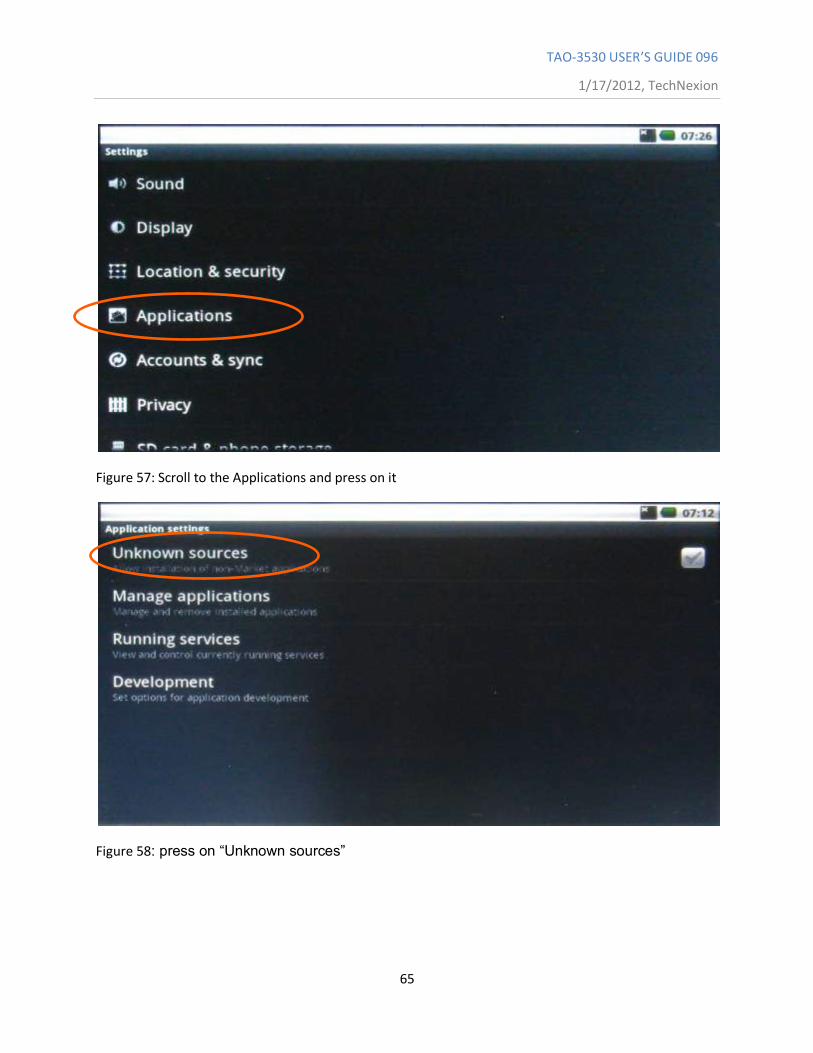
Figure 57: Scroll to the Applications and press on it
Figure 58: press on “Unknown sources”
TAO-3530 USER’S GUIDE 096
1/17/2012, TechNexion
66
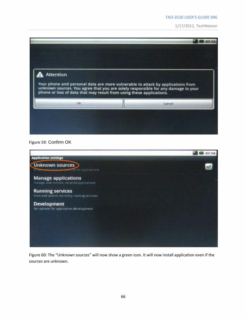
Figure 59: Confirm OK
Figure 60: The “Unknown sources” will now show a green icon. It will now install application even if the
sources are unknown.
TAO-3530 USER’S GUIDE 096
1/17/2012, TechNexion
67
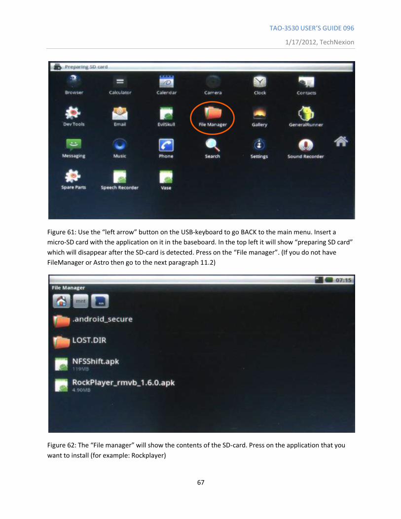
Figure 61: Use the “left arrow” button on the USB-keyboard to go BACK to the main menu. Insert a
micro-SD card with the application on it in the baseboard. In the top left it will show “preparing SD card”
which will disappear after the SD-card is detected. Press on the “File manager”. (If you do not have
FileManager or Astro then go to the next paragraph 11.2)
Figure 62: The “File manager” will show the contents of the SD-card. Press on the application that you
want to install (for example: Rockplayer)
TAO-3530 USER’S GUIDE 096
1/17/2012, TechNexion
68
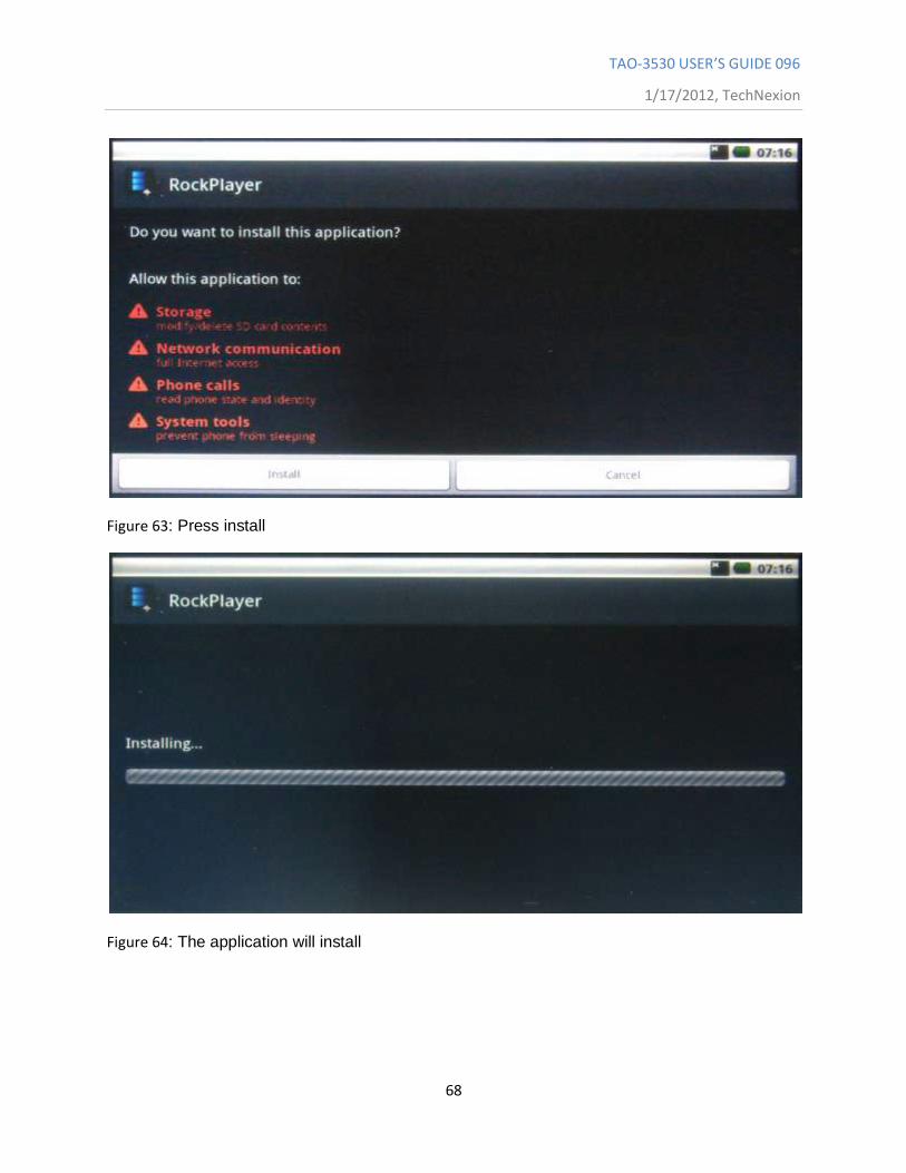
Figure 63: Press install
Figure 64: The application will install
TAO-3530 USER’S GUIDE 096
1/17/2012, TechNexion
69
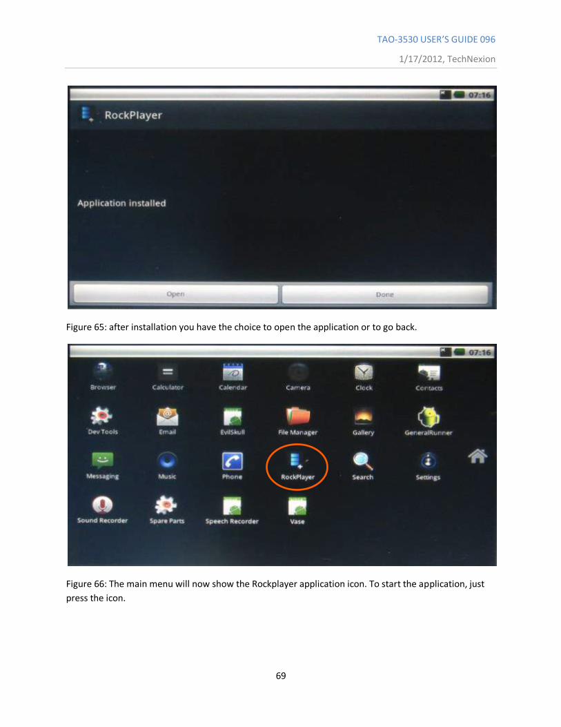
Figure 65: after installation you have the choice to open the application or to go back.
Figure 66: The main menu will now show the Rockplayer application icon. To start the application, just
press the icon.
TAO-3530 USER’S GUIDE 096
1/17/2012, TechNexion
70
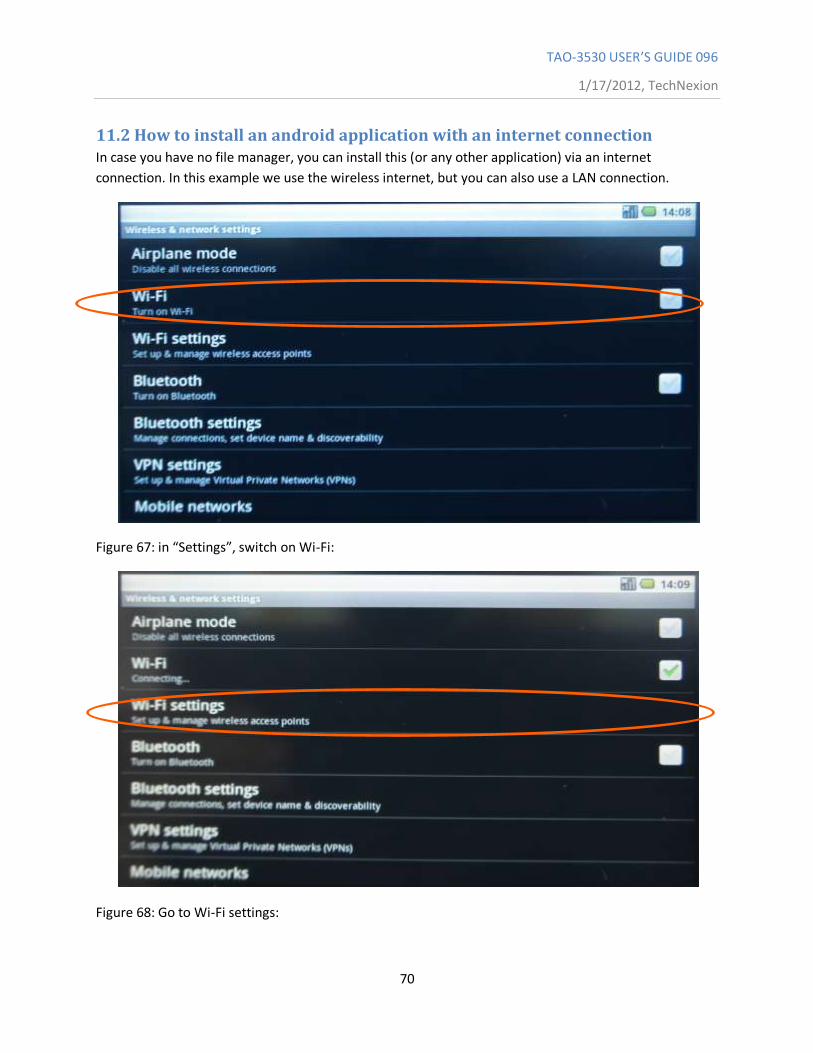
11.2 How to install an android application with an internet connection In case you have no file manager, you can install this (or any other application) via an internet
connection. In this example we use the wireless internet, but you can also use a LAN connection.
Figure 67: in “Settings”, switch on Wi-Fi:
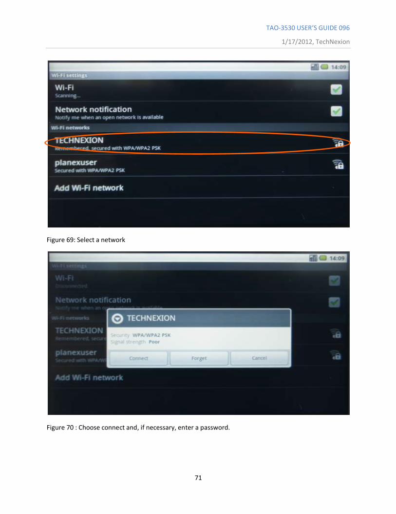
Figure 68: Go to Wi-Fi settings:
TAO-3530 USER’S GUIDE 096
1/17/2012, TechNexion
71
Figure 69: Select a network
Figure 70 : Choose connect and, if necessary, enter a password.
TAO-3530 USER’S GUIDE 096
1/17/2012, TechNexion
72
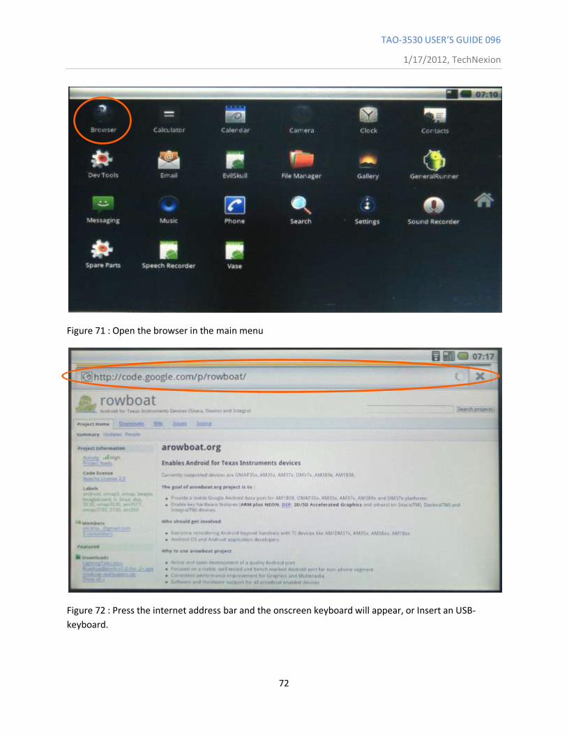
Figure 71 : Open the browser in the main menu
Figure 72 : Press the internet address bar and the onscreen keyboard will appear, or Insert an USB-
keyboard.
TAO-3530 USER’S GUIDE 096
1/17/2012, TechNexion
73
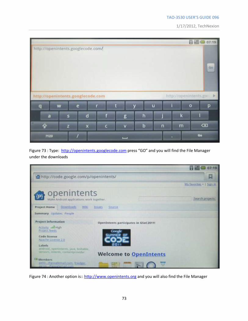
Figure 73 : Type: http://openintents.googlecode.com press “GO” and you will find the File Manager
under the downloads
Figure 74 : Another option is:: http://www.openintents.org and you will also find the File Manager
TAO-3530 USER’S GUIDE 096
1/17/2012, TechNexion
74
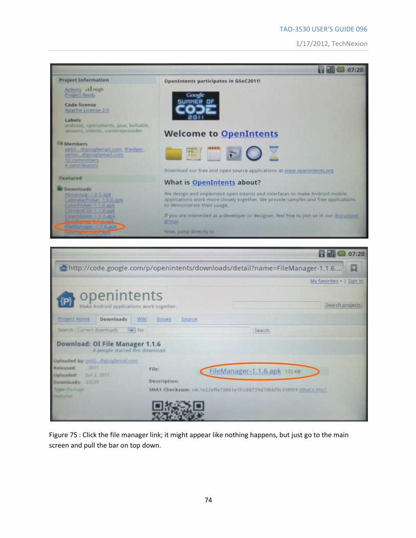
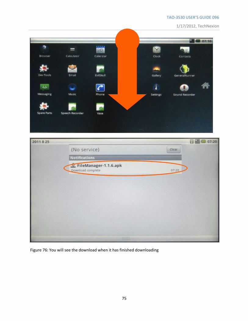
Figure 75 : Click the file manager link; it might appear like nothing happens, but just go to the main
screen and pull the bar on top down.
TAO-3530 USER’S GUIDE 096
1/17/2012, TechNexion
75
Figure 76: You will see the download when it has finished downloading
TAO-3530 USER’S GUIDE 096
1/17/2012, TechNexion
76
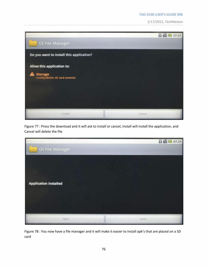
Figure 77 : Press the download and it will ask to install or cancel, Install will install the application, and
Cancel will delete the file
Figure 78 : You now have a file manager and it will make it easier to install apk’s that are placed on a SD
card
TAO-3530 USER’S GUIDE 096
1/17/2012, TechNexion
77
11.3 ADB - Installing applications
11.3.1 Windows
Source of information (in this paragraph): [1]
When it comes to Android modding, most novice users are confused or left wondering by reference over reference to a certain “ADB”. This is especially true when you are looking up something on modding your device, or root it in particular. ADB is the wonder toy of Android and everyone seems to love it, so let‟s have a look at understanding what it is and why you need it,
and how you can get it.
11.3.1.1 What is ADB
ADB stands for Android Debug Bridge. It comes as a part of the standard Android SDK, which you can grab here. Basically, it provides a terminal-based interface for interacting with your phone‟s file system. Since Android platform is based on Linux, command-line is the only way to obtain and manipulate root access often required to perform certain advanced operations on
your device using root access.
While these things can be done directly on the device itself using some terminal emulator, it will be rather difficult to execute complex commands on such a small screen. ADB provides the
bridge between your machine and your computer.
11.3.1.2 How to Install ADB
Step 1: Installing the Android SDK
Note: At the time of updating this guide, the latest version of the Android SDK available is r8
and we shall be using it throughout the rest of the guide. The tools will work the same way however, even if you get a later version. In case of earlier versions though, the location of some
of the tools was different and it is recommended that you get the latest available version.
The first step is to download the SDK. Use the link given at the end of this post and download the latest version of the Android SDK from there. There are versions available for Microsoft Windows, Linux and Mac OS X. In case of Windows, both an installer and a zip file are available but there isn‟t any need to use the installer as a formal installation is not required.
Once you have downloaded the SDK, simply extract the compressed file to a location on your computer. In our case, we have extracted it to the root of our C drive and that makes C:\android-sdk-windows the installation location of the SDK. From here onwards, we shall be referring to
this location as the „SDK folder‟.
Step 2: Downloading the SDK Platform Tools
TAO-3530 USER’S GUIDE 096
1/17/2012, TechNexion
78
Previously, ADB used to be included in the SDK by default in the „tools‟ sub-folder but now, it has been relocated to the „platform-tools‟ sub-folder which needs to be downloaded as an SDK package. Fortunately, this is quite easy:
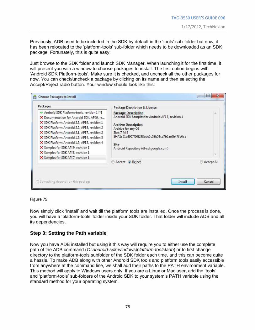
Just browse to the SDK folder and launch SDK Manager. When launching it for the first time, it will present you with a window to choose packages to install. The first option begins with „Android SDK Platform-tools‟. Make sure it is checked, and uncheck all the other packages for now. You can check/uncheck a package by clicking on its name and then selecting the
Accept/Reject radio button. Your window should look like this:
Figure 79
Now simply click „Install‟ and wait till the platform tools are installed. Once the process is done, you will have a „platform-tools‟ folder inside your SDK folder. That folder will include ADB and all
its dependencies.
Step 3: Setting the Path variable
Now you have ADB installed but using it this way will require you to either use the complete path of the ADB command (C:\android-sdk-windows\platform-tools\adb) or to first change
directory to the platform-tools subfolder of the SDK folder each time, and this can become quite a hassle. To make ADB along with other Android SDK tools and platform tools easily accessible from anywhere at the command line, we shall add their paths to the PATH environment variable. This method will apply to Windows users only. If you are a Linux or Mac user, add the „tools‟ and „platform-tools‟ sub-folders of the Android SDK to your system‟s PATH variable using the standard method for your operating system.
TAO-3530 USER’S GUIDE 096
1/17/2012, TechNexion
79
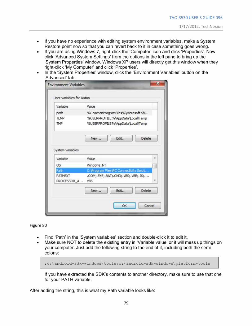
If you have no experience with editing system environment variables, make a System Restore point now so that you can revert back to it in case something goes wrong.
If you are using Windows 7, right-click the „Computer‟ icon and click „Properties‟. Now click „Advanced System Settings‟ from the options in the left pane to bring up the „System Properties‟ window. Windows XP users will directly get this window when they right-click „My Computer‟ and click „Properties‟.
In the „System Properties‟ window, click the „Environment Variables‟ button on the „Advanced‟ tab.
Figure 80
Find „Path‟ in the „System variables‟ section and double-click it to edit it. Make sure NOT to delete the existing entry in „Variable value‟ or it will mess up things on
your computer. Just add the following string to the end of it, including both the semi-
colons:
;c:\android-sdk-windows\tools;c:\android-sdk-windows\platform-tools
If you have extracted the SDK‟s contents to another directory, make sure to use that one for your PATH variable.
After adding the string, this is what my Path variable looks like:
TAO-3530 USER’S GUIDE 096
1/17/2012, TechNexion
80
C:\Program Files\Common Files\Microsoft Shared\Windows Live;C:\Program Files
(x86)\Common Files\Microsoft Shared\Windows
Live;%SystemRoot%\system32;%SystemRoot%;%SystemRoot%\System32\Wbem;%SYSTEMROO
T%\System32\WindowsPowerShell\v1.0\;C:\Program Files (x86)\ATI
Technologies\ATI.ACE\Core-Static;C:\Program Files (x86)\Windows
Live\Shared;C:\Program Files\Java\jdk1.6.0_23\bin;C:\Program Files
(x86)\Java\jdk1.6.0_23\bin;C:\android-sdk-windows\tools;C:\android-sdk-
windows\platform-tools
Don‟t worry if yours does not include some of the other text – what is important is the way the new entry should be added to the existign one, and the way the previous entries MUST be left unchanged. Notice that the semi-colons are necessary to separate each path variable entry from the next and previous ones. Once you have added the path, your machine may require a
reboot.
In case you messed up while editing the Path variable and ended up deleting the previously existing entries, just restore the System Restore point you made and retry, being more careful
this time.
Step 4: Installing the USB drivers
Finally, you need to install the USB drivers. You may or may not need to perform this step, depending on your device. If you are using a device that ships with stock Android operating system such as the Nexus One, this will be necessary. In case of other devices that ship with their custom version of Android and some tools to sync the device with the PC, such as devices from HTC that ship with HTC Sync or devices by Samsung that ship with Samsung‟s own software, the suitable driver for your device will be automatically installed with that software
package.
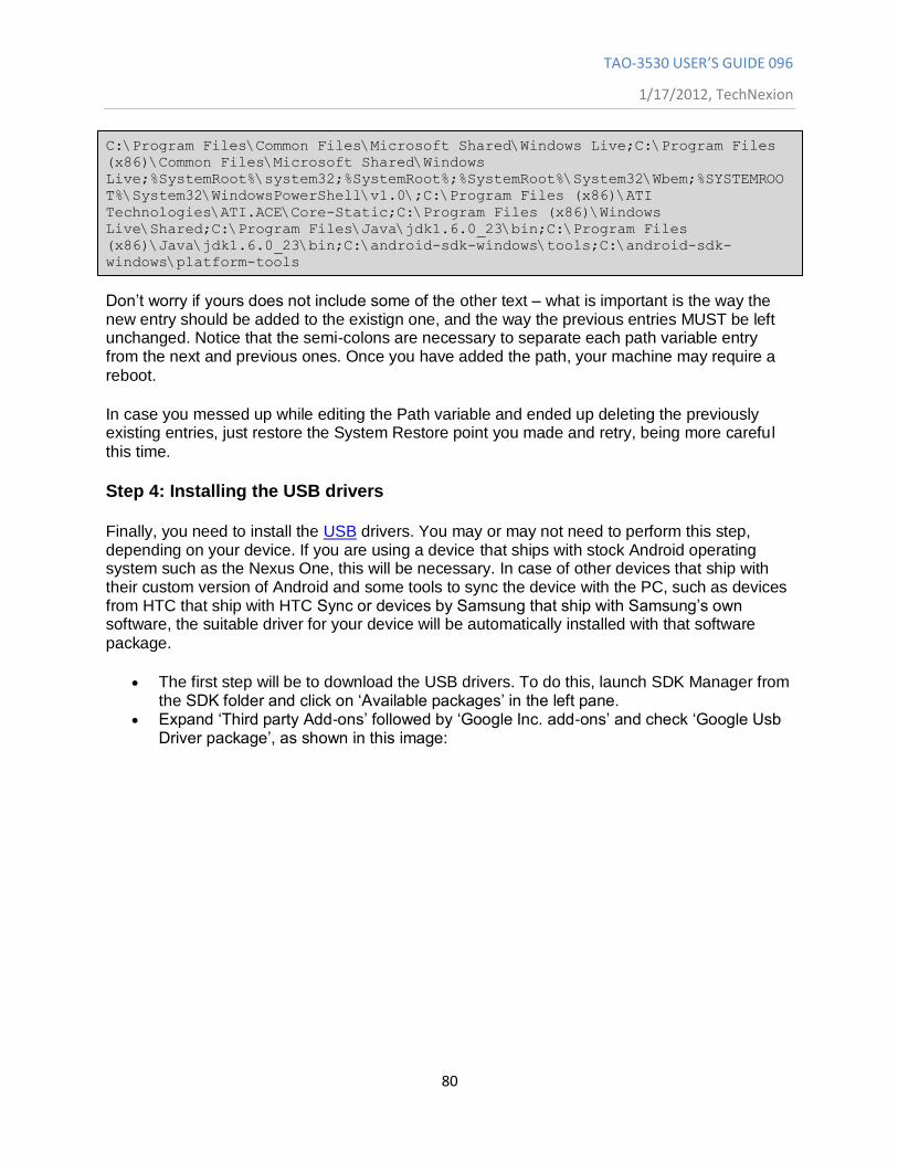
The first step will be to download the USB drivers. To do this, launch SDK Manager from the SDK folder and click on „Available packages‟ in the left pane.
Expand „Third party Add-ons‟ followed by „Google Inc. add-ons‟ and check „Google Usb Driver package‟, as shown in this image:
TAO-3530 USER’S GUIDE 096
1/17/2012, TechNexion
81
Figure 81
Click „Install Selected‟ and in the window that pops up, click the „Accept all‟ radio button followed by the „Install‟ button. Wait patiently while the USB drivers are downloaded and installed in the Android SDK.
The drivers for both 32 bit and 64 bit systems will now be present in the SDK folder
under „usb_driver\x86′ and „usb_driver\x64′ sub-folders respectively.
Now that the USB drivers have been downloaded, you can install them to your computer as follows:
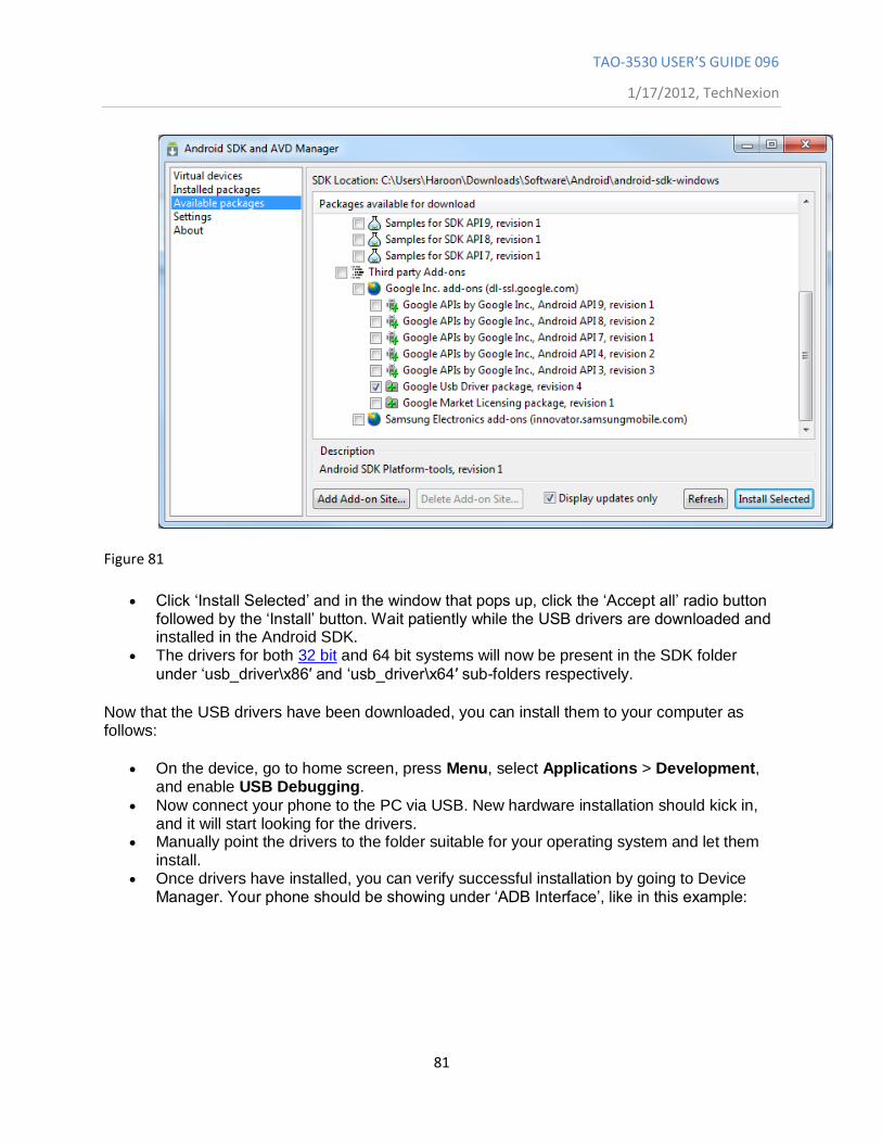
On the device, go to home screen, press Menu, select Applications > Development, and enable USB Debugging.
Now connect your phone to the PC via USB. New hardware installation should kick in, and it will start looking for the drivers.
Manually point the drivers to the folder suitable for your operating system and let them install.
Once drivers have installed, you can verify successful installation by going to Device Manager. Your phone should be showing under „ADB Interface‟, like in this example:
TAO-3530 USER’S GUIDE 096
1/17/2012, TechNexion
82
Figure 82
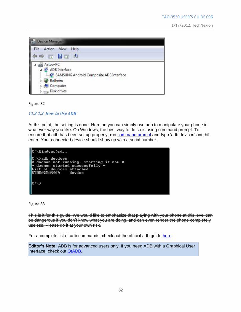
11.3.1.3 How to Use ADB
At this point, the setting is done. Here on you can simply use adb to manipulate your phone in whatever way you like. On Windows, the best way to do so is using command prompt. To ensure that adb has been set up properly, run command prompt and type „adb devices‟ and hit
enter. Your connected device should show up with a serial number.
Figure 83
This is it for this guide. We would like to emphasize that playing with your phone at this level can be dangerous if you don‟t know what you are doing, and can even render the phone completely
useless. Please do it at your own risk.
For a complete list of adb commands, check out the official adb guide here.
Editor’s Note: ADB is for advanced users only. If you need ADB with a Graphical User
Interface, check out QtADB.
TAO-3530 USER’S GUIDE 096
1/17/2012, TechNexion
83
11.3.1.4 Summary
Download
Download JRE/JDK
Above two will install the Android SDK.
When plug in our device, Windows will prompt that a new device is found, and asks for driver.
Please install with the drivers we provide.
11.3.2 Linux
Download
tar zxvf ~/android-sdk_r08-linux_86.tgz cd android-sdk-linux_86
The folder structure should be
Add-ons Platforms SDK Readme.txt Tools
Most of the utilities are basic, so you need to update:
./tools/android update SDK
It will launch a GUI interface. Install all the packages you need.
Now the "ADB" is in the folder "platform-tools", you can add it to your path.
11.3.2.1 Connect by USB
Connect USB-otg on TAO to host machine
Turn on USB Debug
MENU->Settings->Applications->Development and then enable the "USB debugging" option.
Setup Host Machine
Log in as root and create this file: /etc/udev/rules.d/51-android.rules
TAO-3530 USER’S GUIDE 096
1/17/2012, TechNexion
84
For Gusty/Hardy, edit the file to read: SUBSYSTEM=="usb", SYSFS{idVendor}=="18d1", MODE="0666" For Dapper, edit the file to read: SUBSYSTEM=="usb_device", SYSFS{idVendor}=="18d1", MODE="0666"
Execute the following to change the user mode for the rules file:
host#> chmod a+r /etc/udev/rules.d/51-android.rules
Verify the adb connectivity between host and target board:
host#> adb devices
If device is connected, then output on screen should list the device, example:
List of devices attached 20100720 device
Login use ADB
host#> adb shell
11.3.2.2 Connect by Ethernet
Please make sure Ethernet on both TAO and the host machine are connected to same network Check Ethernet configuration for the board
tao #> netcfg lo UP 127.0.0.1 255.0.0.0 0x00000049 eth0 UP 192.168.70.135 255.255.255.0 0x00001043
If Ethernet was not configured, configure Ethernet of the board using ifconfig/netcfg as shown below.
tao #> netcfg eth0 dhcp
Configure the ADB Daemon to use an Ethernet connection using setprop as shown below.
tao #> setprop service.adb.tcp.port 5555
If network is configured successfully (above steps) then restart service adbd on the target,
tao #> stop adbd tao #> start adbd
On the host machine use following commands to establish the ADB connection
TAO-3530 USER’S GUIDE 096
1/17/2012, TechNexion
85
host#> export ADBHOST=<target's ip address> host#> adb kill-server host#> adb start-server
Verify for device connectivity, by executing the following commands
host#> adb devices
If connected, find the device name listed as an "emulator"
List of devices attached emulator-5554 device
Login use ADB
host#> adb shell
For more information about adb commands, see Android Debug Bridge page at http://developer.android.com/guide/developing/tools/adb.html
11.3.3 ADB Functions
11.3.3.1 Application Install/Remove
Install
$> adb install <package>.apk
Remove
$> adb uninstall <package>.apk
11.3.3.2 File Operation
To Device
$> adb push <local_file_path> <remote_path>
From Device
$> adb pull <remote_file_path> <local_path>
11.3.3.3 Shell Operation $> adb shell
11.3.3.4 Show Devices $> adb devices
TAO-3530 USER’S GUIDE 096
1/17/2012, TechNexion
86
12 Software - Windows CE
12.1 Warning
Warning! Installing software is not easy. Finish the procedure
completely and be patient to let the compilation and installation finish.
Important! To install Windows CE, you need a null modem to see what
is going on.
12.2 Update to Windows Embedded CE6.0 R3
Make sure you have downloaded all R3 patches for Windows Embedded 6.0. The
Patches can be found at Windows Embedded CE6.0 R3 on the Microsoft website.
12.3 Get the BSP
12.3.1 Download the BSP from the web-Site
Go to www.technexion.com > Support > Download Center and download
TAO-3530_WinCE 6_versionnumber.
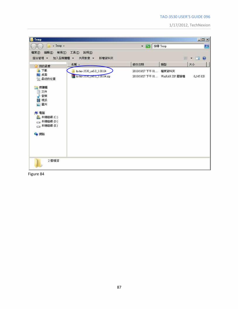
12.3.2 Install BSP to “Platform Builder for CE 6.0”.
Decompress the downloaded file. (See Figure 84)
TAO-3530 USER’S GUIDE 096
1/17/2012, TechNexion
87
Figure 84
TAO-3530 USER’S GUIDE 096
1/17/2012, TechNexion
88
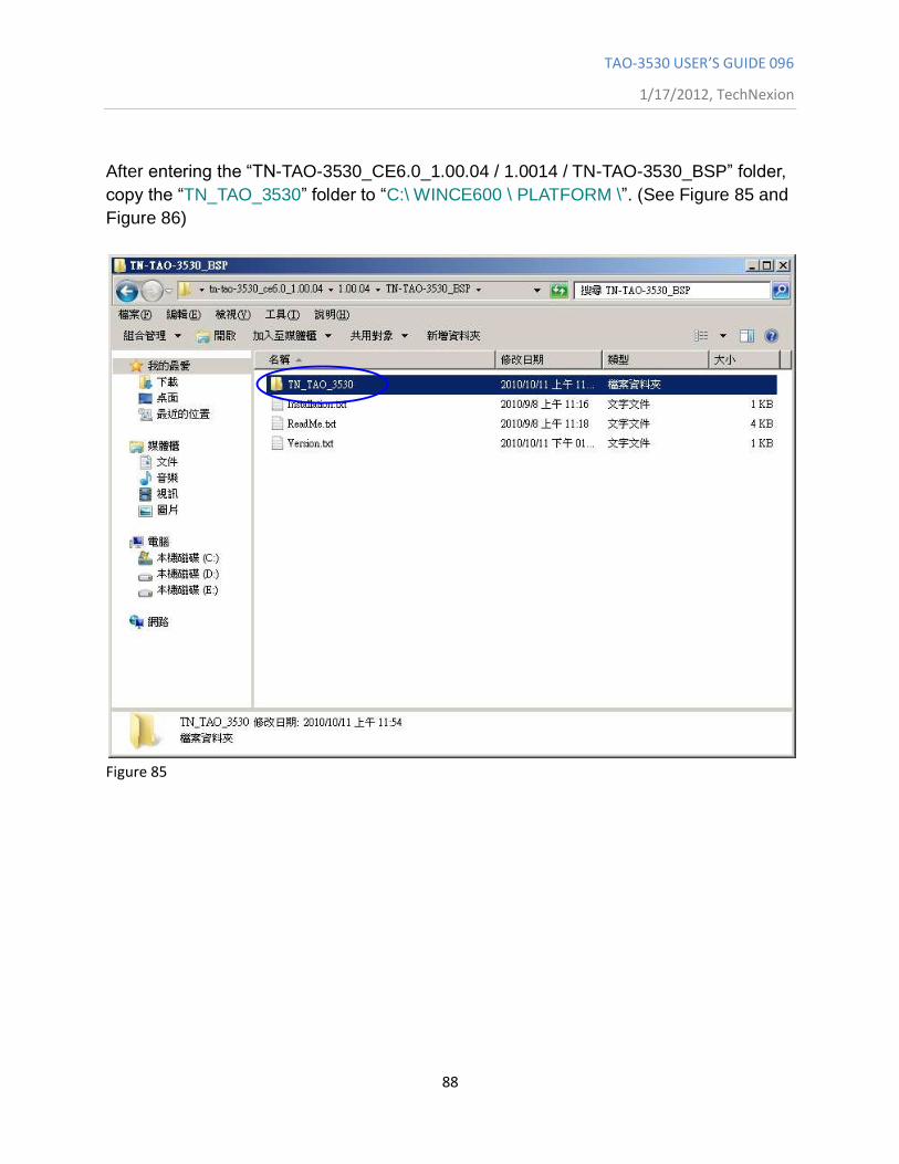
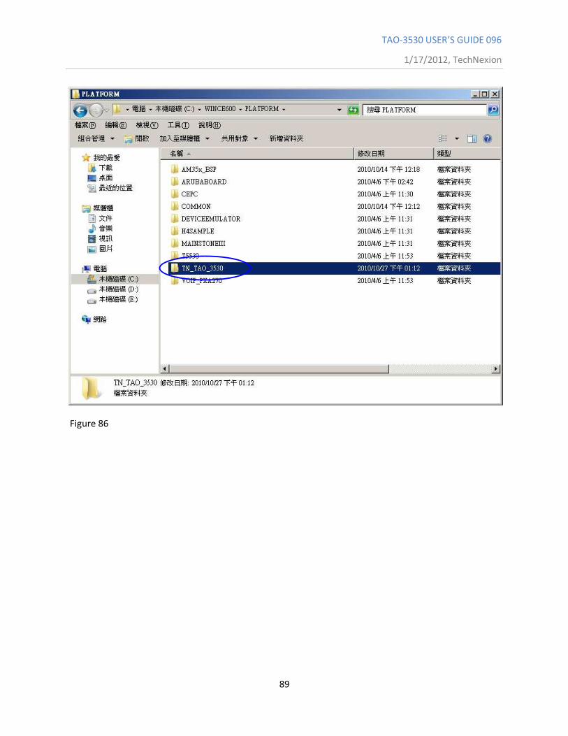
After entering the “TN-TAO-3530_CE6.0_1.00.04 / 1.0014 / TN-TAO-3530_BSP” folder,
copy the “TN_TAO_3530” folder to “C:\ WINCE600 \ PLATFORM \”. (See Figure 85 and
Figure 86)
Figure 85
TAO-3530 USER’S GUIDE 096
1/17/2012, TechNexion
89
Figure 86
TAO-3530 USER’S GUIDE 096
1/17/2012, TechNexion
90
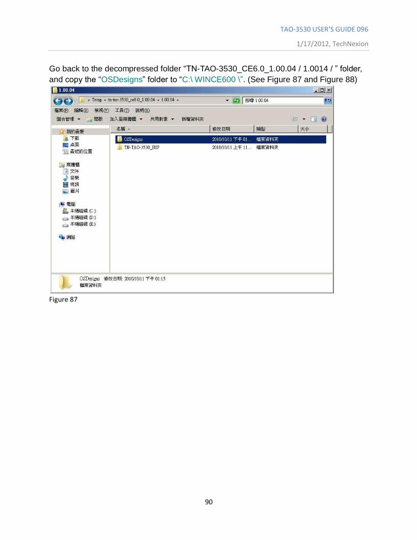
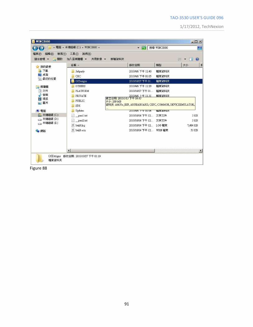
Go back to the decompressed folder “TN-TAO-3530_CE6.0_1.00.04 / 1.0014 / ” folder,
and copy the “OSDesigns” folder to “C:\ WINCE600 \”. (See Figure 87 and Figure 88)
Figure 87
TAO-3530 USER’S GUIDE 096
1/17/2012, TechNexion
91
Figure 88
TAO-3530 USER’S GUIDE 096
1/17/2012, TechNexion
92
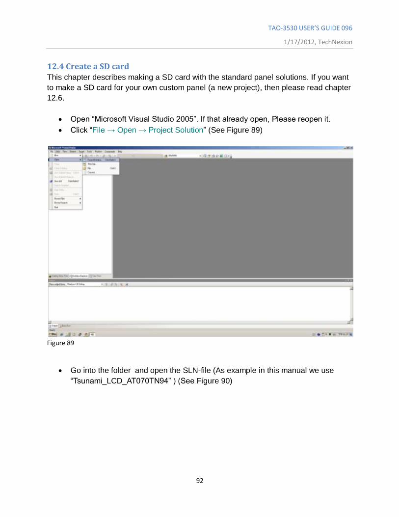
12.4 Create a SD card
This chapter describes making a SD card with the standard panel solutions. If you want
to make a SD card for your own custom panel (a new project), then please read chapter
12.6.
Open “Microsoft Visual Studio 2005”. If that already open, Please reopen it.
Click “File → Open → Project Solution” (See Figure 89)
Figure 89
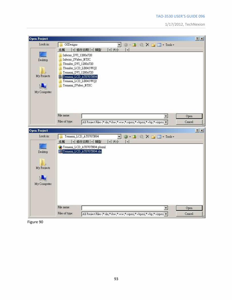
Go into the folder and open the SLN-file (As example in this manual we use
“Tsunami_LCD_AT070TN94” ) (See Figure 90)
TAO-3530 USER’S GUIDE 096
1/17/2012, TechNexion
93
Figure 90
TAO-3530 USER’S GUIDE 096
1/17/2012, TechNexion
94
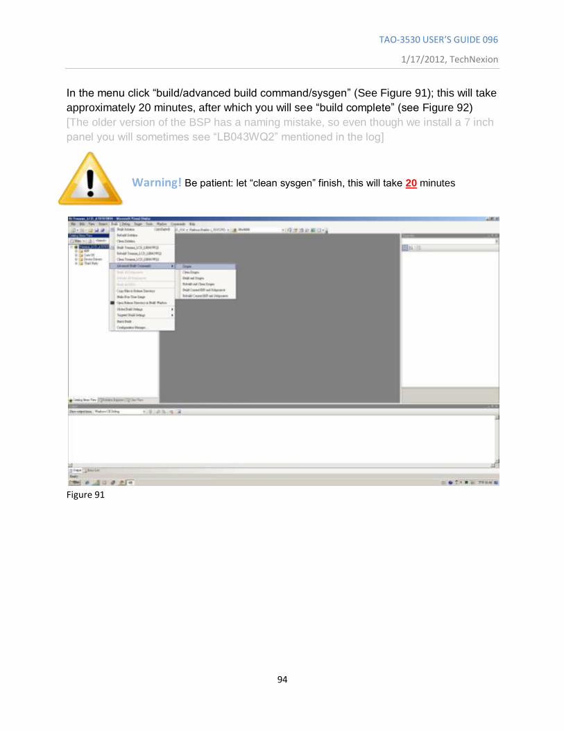
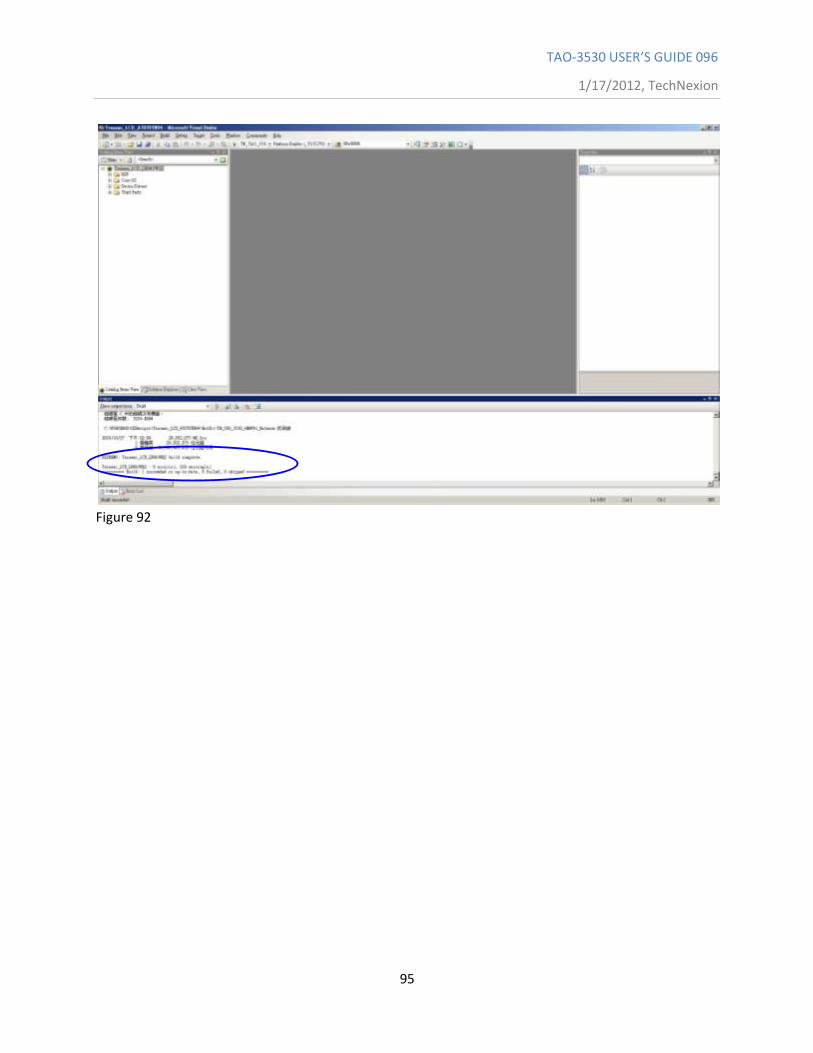
In the menu click “build/advanced build command/sysgen” (See Figure 91); this will take
approximately 20 minutes, after which you will see “build complete” (see Figure 92)
[The older version of the BSP has a naming mistake, so even though we install a 7 inch
panel you will sometimes see “LB043WQ2” mentioned in the log]
Warning! Be patient: let “clean sysgen” finish, this will take 20 minutes
Figure 91
TAO-3530 USER’S GUIDE 096
1/17/2012, TechNexion
95
Figure 92
TAO-3530 USER’S GUIDE 096
1/17/2012, TechNexion
96
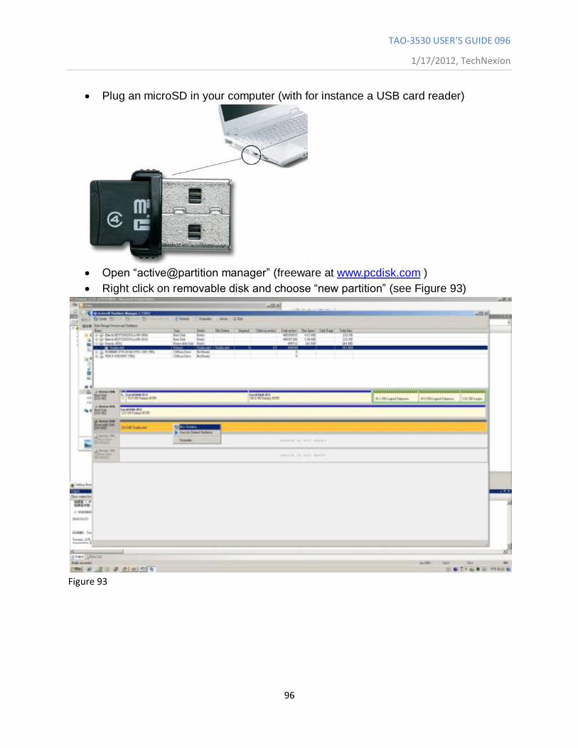
Plug an microSD in your computer (with for instance a USB card reader)
Open “active@partition manager” (freeware at www.pcdisk.com )
Right click on removable disk and choose “new partition” (see Figure 93)
Figure 93
TAO-3530 USER’S GUIDE 096
1/17/2012, TechNexion
97
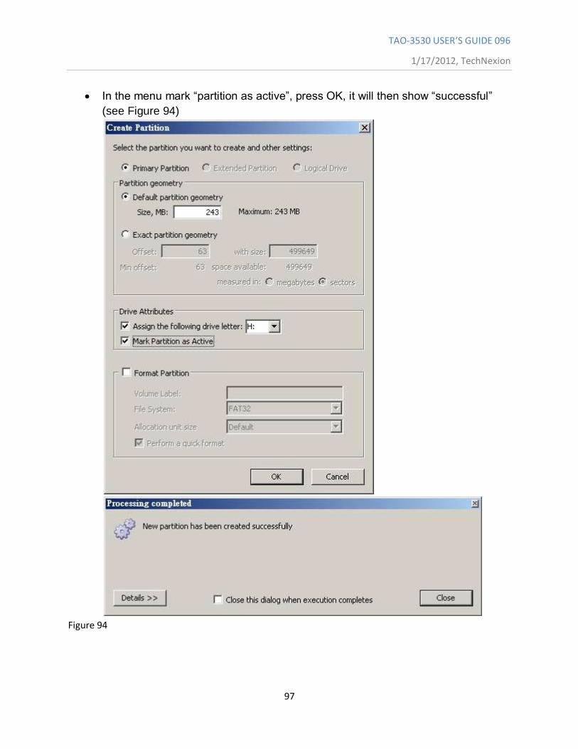
In the menu mark “partition as active”, press OK, it will then show “successful”
(see Figure 94)
Figure 94
TAO-3530 USER’S GUIDE 096
1/17/2012, TechNexion
98
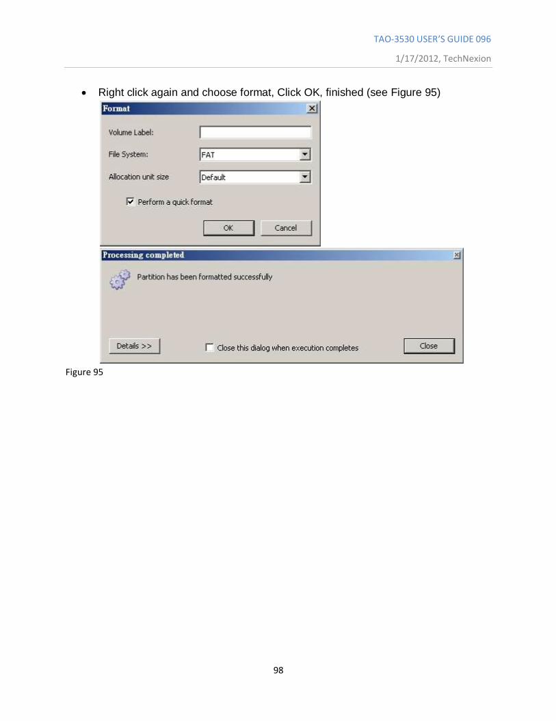
Right click again and choose format, Click OK, finished (see Figure 95)
Figure 95
TAO-3530 USER’S GUIDE 096
1/17/2012, TechNexion
99
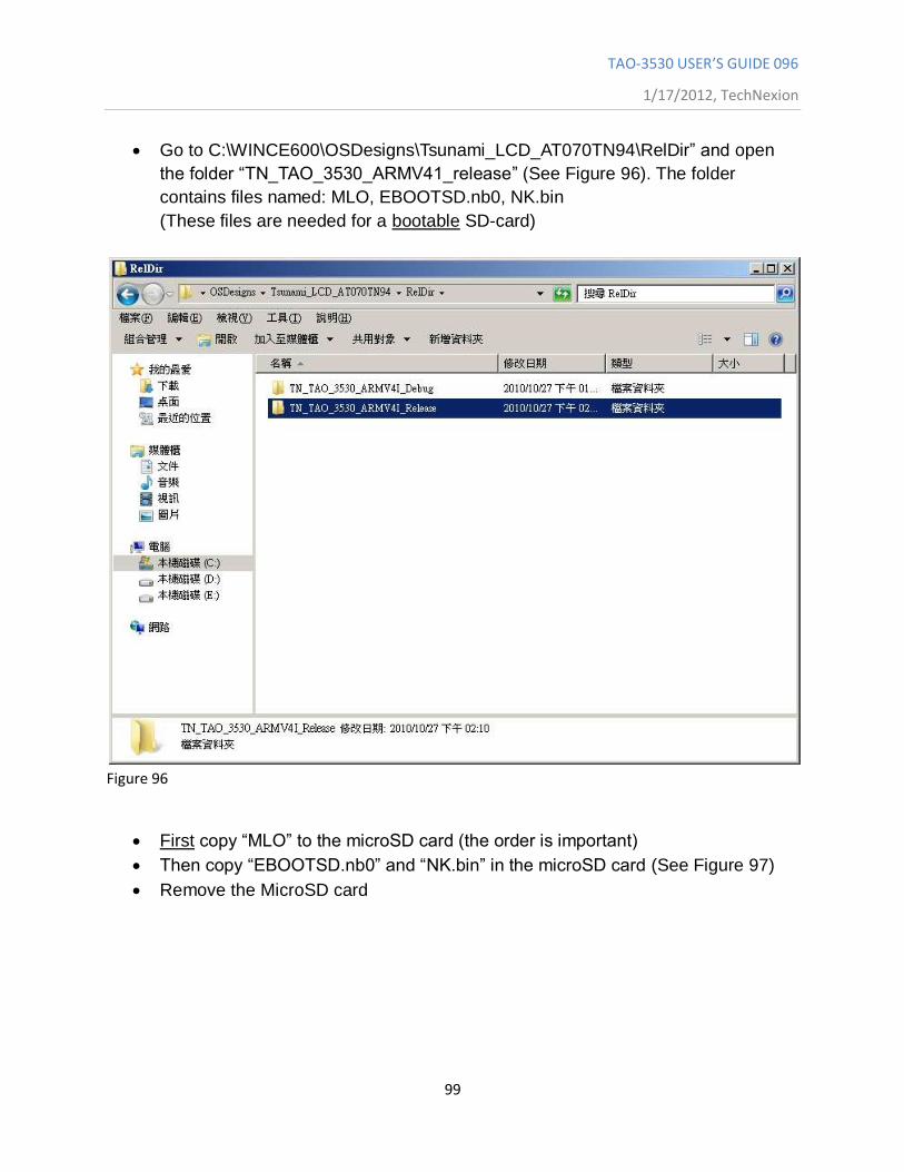
Go to C:\WINCE600\OSDesigns\Tsunami_LCD_AT070TN94\RelDir” and open
the folder “TN_TAO_3530_ARMV41_release” (See Figure 96). The folder
contains files named: MLO, EBOOTSD.nb0, NK.bin
(These files are needed for a bootable SD-card)
Figure 96
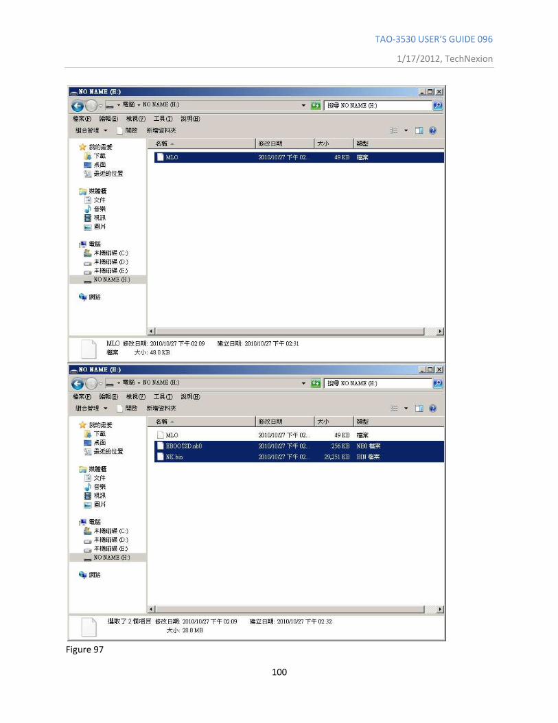
First copy “MLO” to the microSD card (the order is important)
Then copy “EBOOTSD.nb0” and “NK.bin” in the microSD card (See Figure 97)
Remove the MicroSD card
TAO-3530 USER’S GUIDE 096
1/17/2012, TechNexion
100
Figure 97
TAO-3530 USER’S GUIDE 096
1/17/2012, TechNexion
101
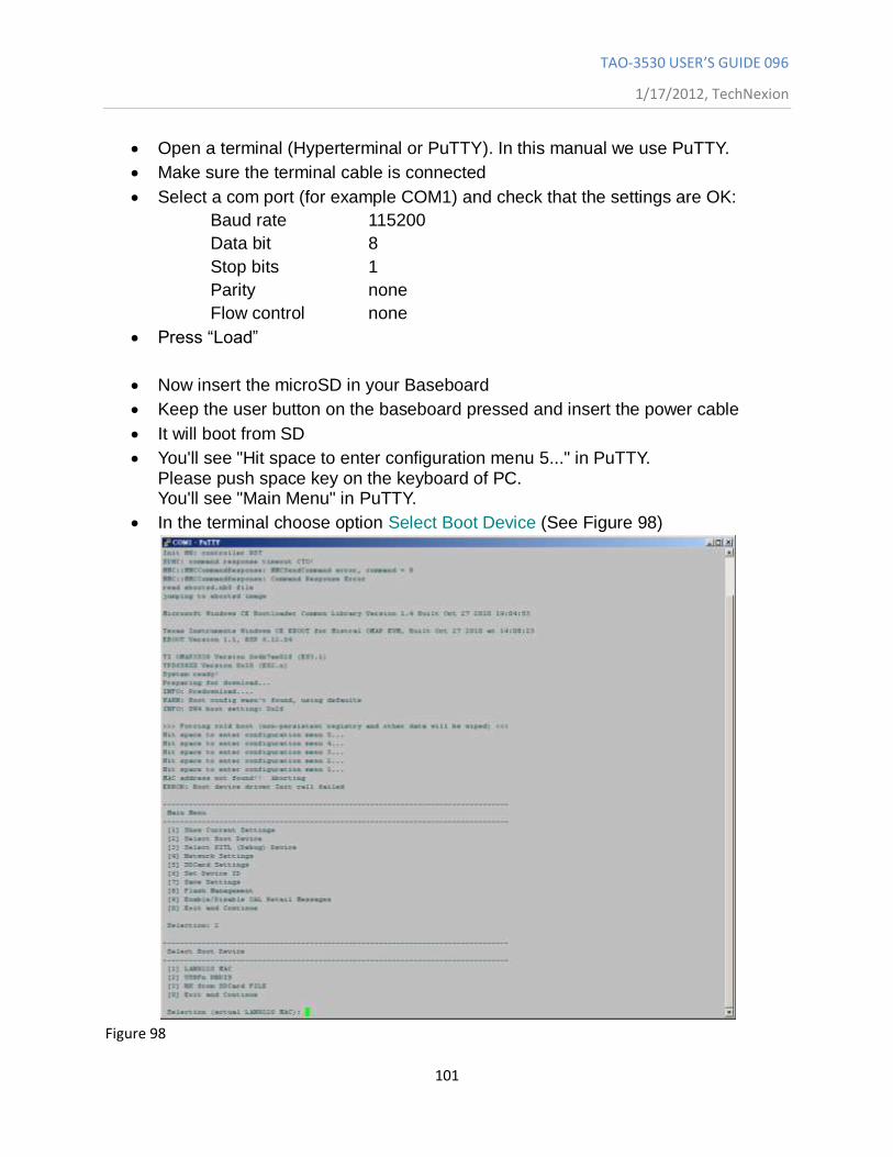
Open a terminal (Hyperterminal or PuTTY). In this manual we use PuTTY.
Make sure the terminal cable is connected
Select a com port (for example COM1) and check that the settings are OK:
Baud rate 115200
Data bit 8
Stop bits 1
Parity none
Flow control none
Press “Load”
Now insert the microSD in your Baseboard
Keep the user button on the baseboard pressed and insert the power cable
It will boot from SD
You'll see "Hit space to enter configuration menu 5..." in PuTTY. Please push space key on the keyboard of PC. You'll see "Main Menu" in PuTTY.
In the terminal choose option Select Boot Device (See Figure 98)
Figure 98
TAO-3530 USER’S GUIDE 096
1/17/2012, TechNexion
102
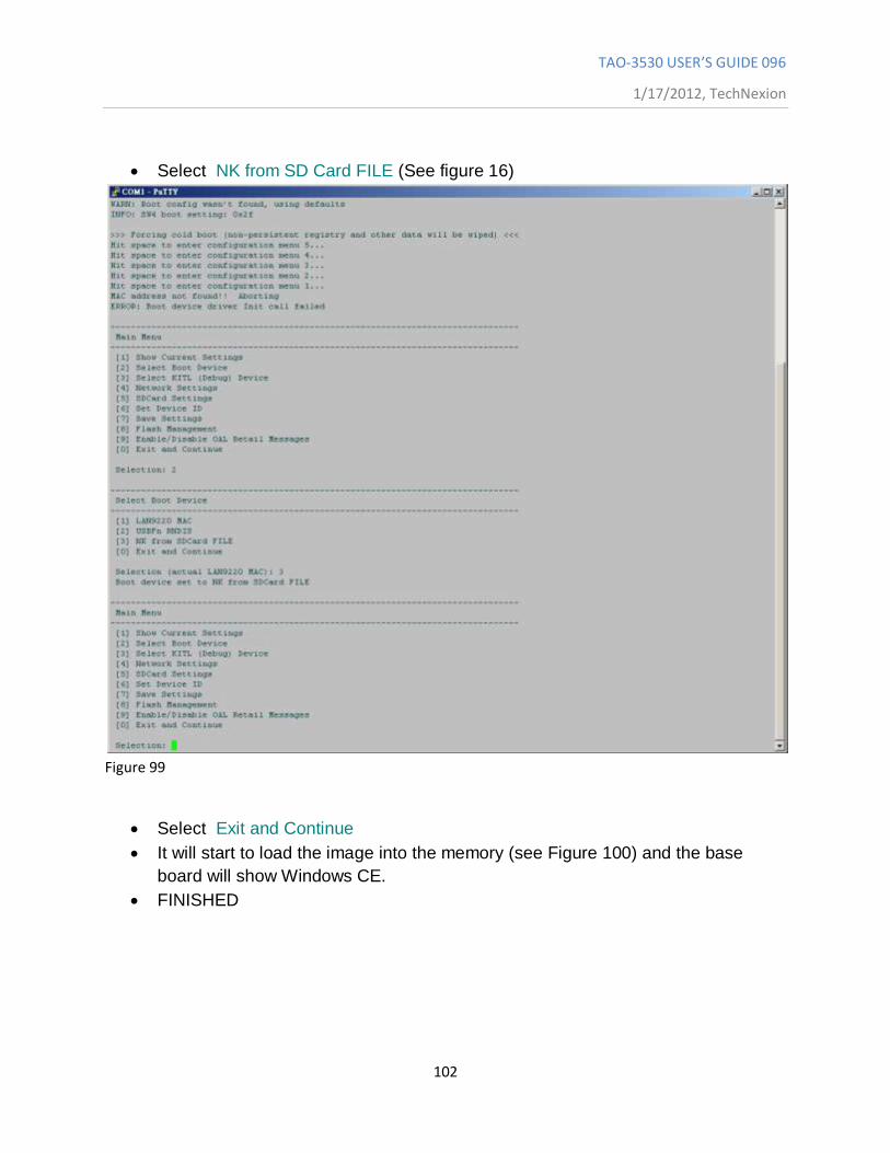
Select NK from SD Card FILE (See figure 16)
Figure 99
Select Exit and Continue
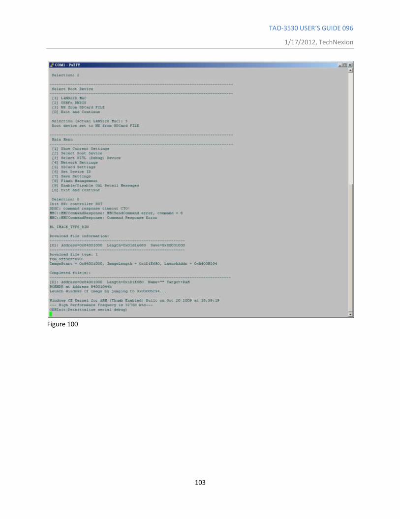
It will start to load the image into the memory (see Figure 100) and the base
board will show Windows CE.
FINISHED
TAO-3530 USER’S GUIDE 096
1/17/2012, TechNexion
103
Figure 100
TAO-3530 USER’S GUIDE 096
1/17/2012, TechNexion
104
12.5 How to put the WinCE image in the NAND Flash
In the previous section we showed how to boot from a SD card. Now we explain how to
put the image in the NAND Flash so you can boot without the SD card.
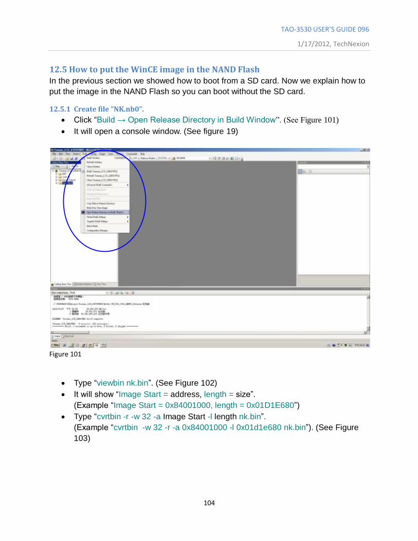
12.5.1 Create file “NK.nb0”.
Click “Build → Open Release Directory in Build Window”. (See Figure 101)
It will open a console window. (See figure 19)
Figure 101
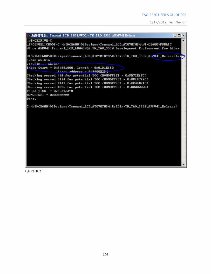
Type “viewbin nk.bin”. (See Figure 102)
It will show “Image Start = address, length = size”.
(Example “Image Start = 0x84001000, length = 0x01D1E680”)
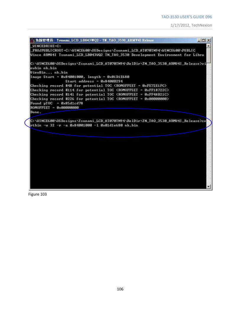
Type “cvrtbin -r -w 32 -a Image Start -l length nk.bin”.
(Example “cvrtbin -w 32 -r -a 0x84001000 -l 0x01d1e680 nk.bin”). (See Figure
103)
TAO-3530 USER’S GUIDE 096
1/17/2012, TechNexion
105
Figure 102
TAO-3530 USER’S GUIDE 096
1/17/2012, TechNexion
106
Figure 103
TAO-3530 USER’S GUIDE 096
1/17/2012, TechNexion
107
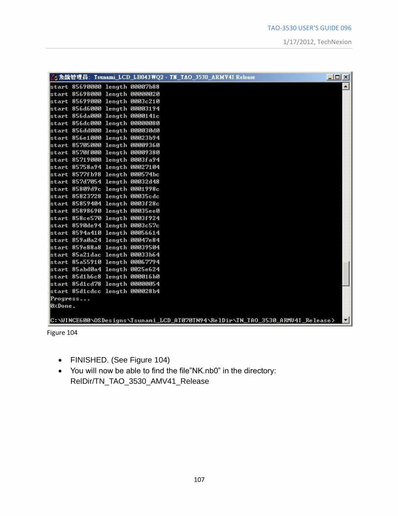
Figure 104
FINISHED. (See Figure 104)
You will now be able to find the file”NK.nb0” in the directory:
RelDir/TN_TAO_3530_AMV41_Release
TAO-3530 USER’S GUIDE 096
1/17/2012, TechNexion
108
12.5.2 Write the Bootloader and OS image to the NAND Flash.
Format the SD Card with the USB Card Reader in the computer, using “Active@
Partition Manager” or another utility.
Mark “partition as active”
This needs “MLO”, “EBOOTSD.nb0”, “fldr.raw” or “fldrlogo.raw” and “nk.nb0”.
These are in “C:\WINCE60\OSDesigns\Project Name\
RelDir\TN_TAO_3530_ARMV4I_Release\”.
(Note: for installing into NAND we need the nk.nb0, this is different from the
nk.bin we used for the bootable SD-card)
You can choose between “fldr.raw” or “fldrlogo.raw” (the end result will be the
same). Fldr.raw will, during boot up, show a screen divided in four different colors.
Fldrlogo.raw will, during boot up, show a dark screen with a TechNexion logo. If
you want your own logo to appear then please read chapter 12.7.
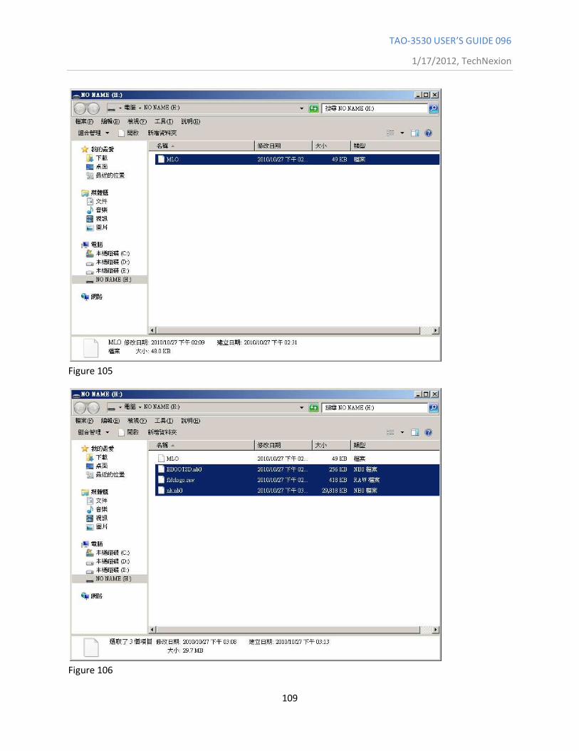
First copy only the “MLO” file to the SD card. (the order is important) See Figure
105)
Then copy “EBOOTSD.nb0”, “fldr.raw” or “fldrlogo.raw” and “nk.nb0” files to the
SD card. (see Figure 106)
Connect the UART cable. Open terminal setting:
Chose Serial port: COM1 or other
Speed: 115200
Data bits: 8
Stop bits: 1
Parity: None
Flow Control: None
Insert SD Card into the target board. Keep USER1 bottom pushed in. Then
connect the power cable.
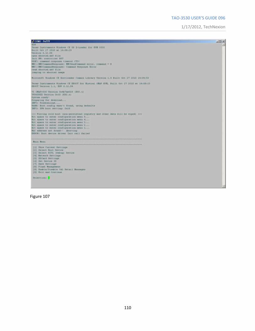
When it shows “Hit space to enter configuration menu”. Please push space
button on the keyboard.
It will show “Main Menu” in the terminal. (See Figure 107 )
TAO-3530 USER’S GUIDE 096
1/17/2012, TechNexion
109
Figure 105
Figure 106
TAO-3530 USER’S GUIDE 096
1/17/2012, TechNexion
110
Figure 107
TAO-3530 USER’S GUIDE 096
1/17/2012, TechNexion
111
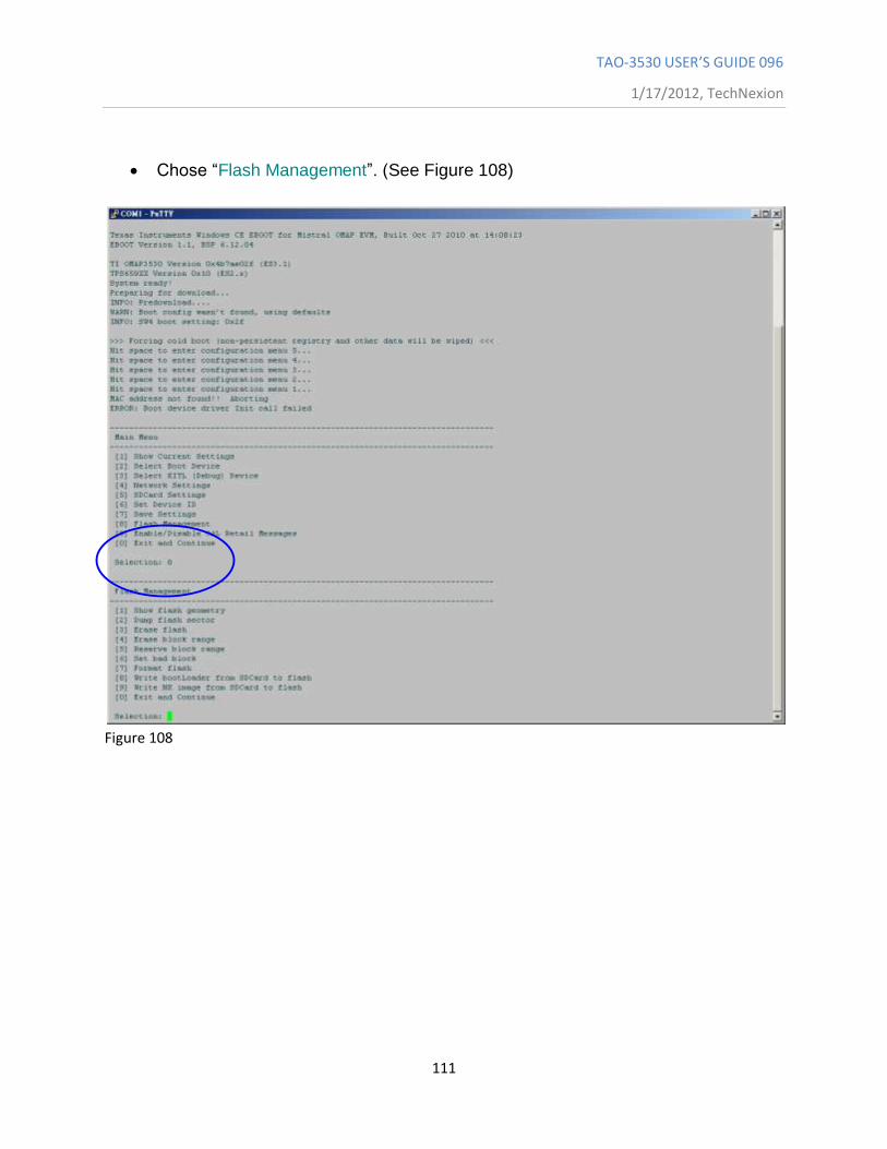
Chose “Flash Management”. (See Figure 108)
Figure 108
TAO-3530 USER’S GUIDE 096
1/17/2012, TechNexion
112
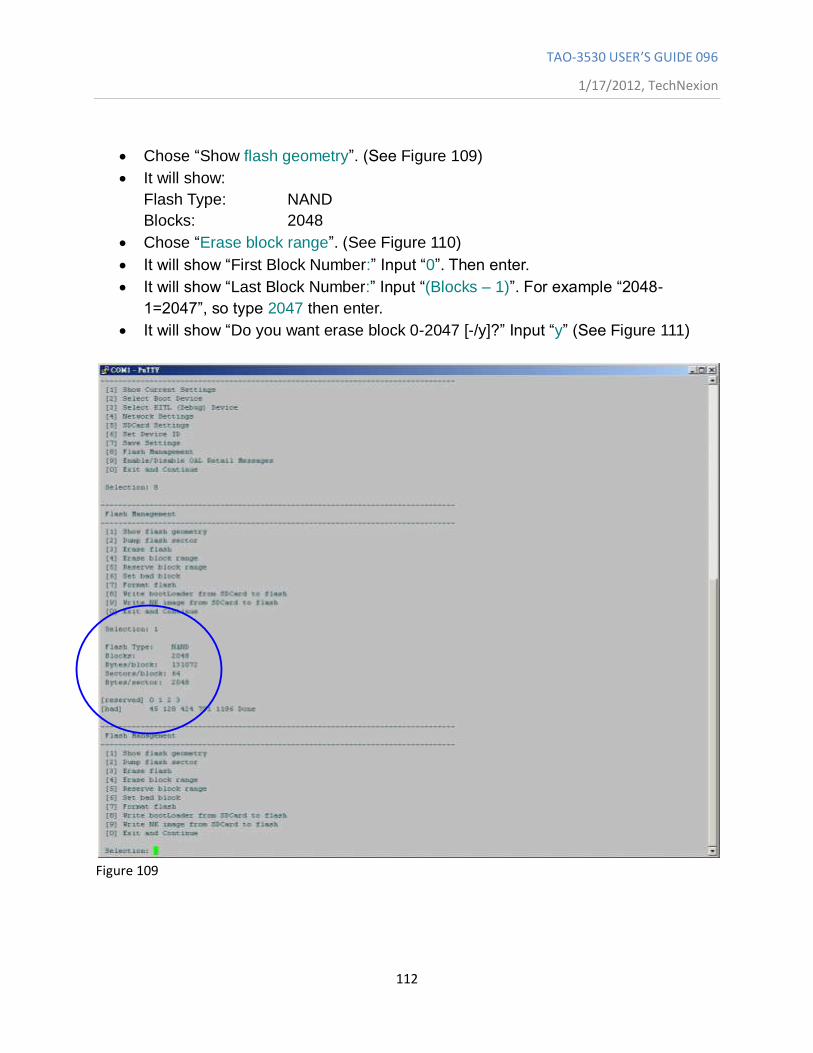
Chose “Show flash geometry”. (See Figure 109)
It will show:
Flash Type: NAND
Blocks: 2048
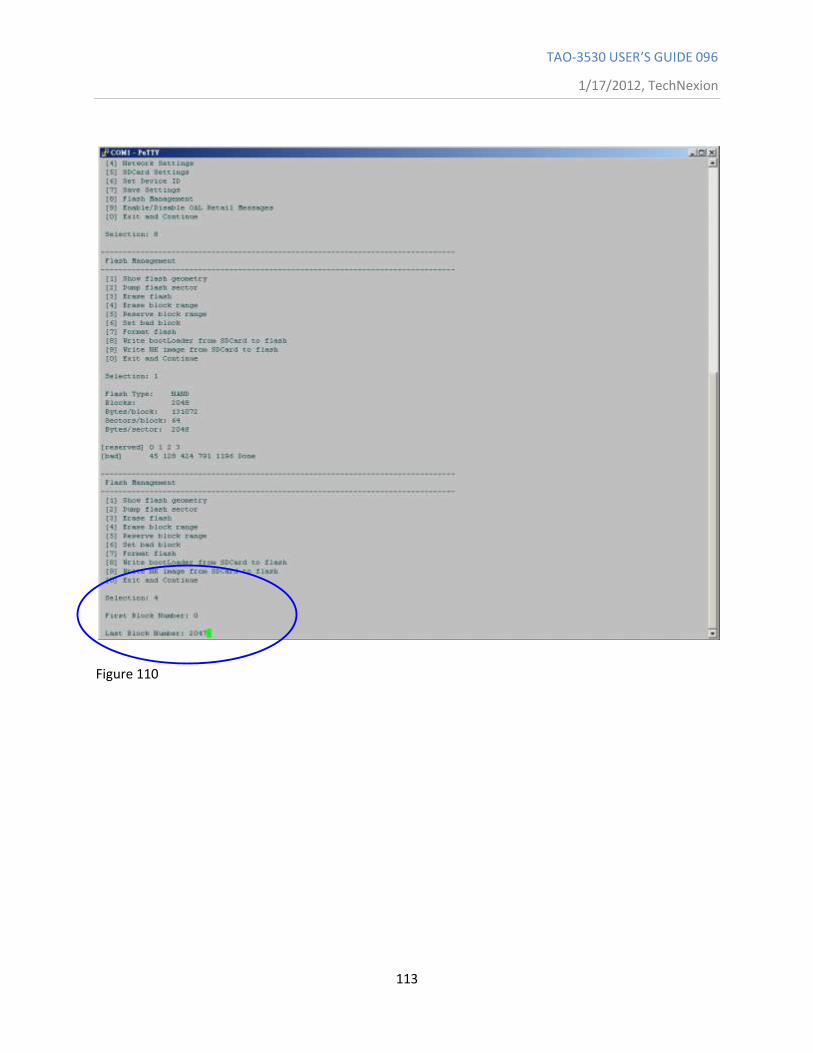
Chose “Erase block range”. (See Figure 110)
It will show “First Block Number:” Input “0”. Then enter.
It will show “Last Block Number:” Input “(Blocks – 1)”. For example “2048-
1=2047”, so type 2047 then enter.
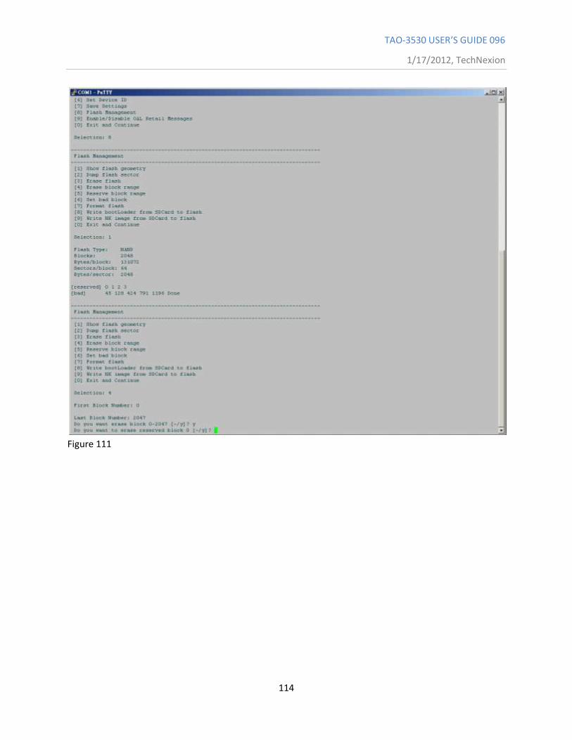
It will show “Do you want erase block 0-2047 [-/y]?” Input “y” (See Figure 111)
Figure 109
TAO-3530 USER’S GUIDE 096
1/17/2012, TechNexion
113
Figure 110
TAO-3530 USER’S GUIDE 096
1/17/2012, TechNexion
114
Figure 111
TAO-3530 USER’S GUIDE 096
1/17/2012, TechNexion
115
Chose “Write Bootloader from SD-Card to flash”. (See Figure 112)
It will show “Do you want to write Bootloader to flash [-/y]?” Input “y”
Then it will show “Bootloader Image written”. (See Figure 113)
Figure 112
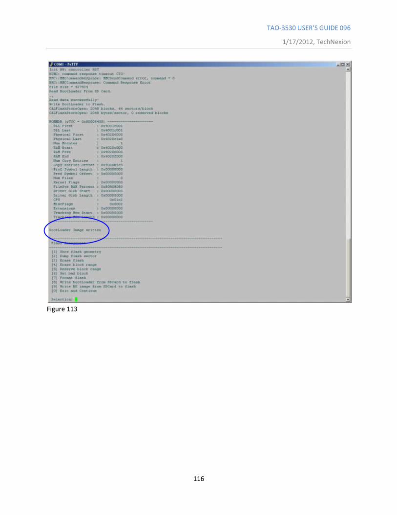
TAO-3530 USER’S GUIDE 096
1/17/2012, TechNexion
116
Figure 113
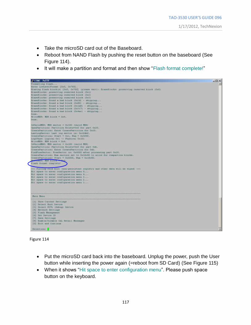
TAO-3530 USER’S GUIDE 096
1/17/2012, TechNexion
117
Take the microSD card out of the Baseboard.
Reboot from NAND Flash by pushing the reset button on the baseboard (See
Figure 114).
It will make a partition and format and then show “Flash format complete!”
Figure 114
Put the microSD card back into the baseboard. Unplug the power, push the User
button while inserting the power again (=reboot from SD Card) (See Figure 115)
When it shows “Hit space to enter configuration menu”. Please push space
button on the keyboard.
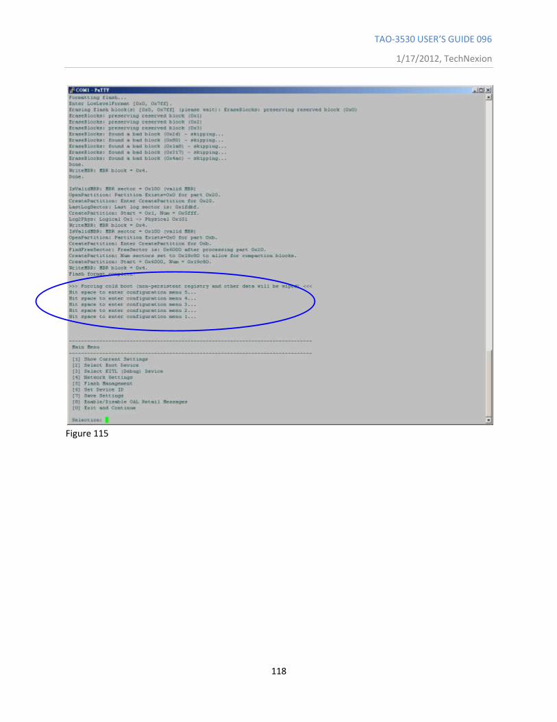
TAO-3530 USER’S GUIDE 096
1/17/2012, TechNexion
118
Figure 115
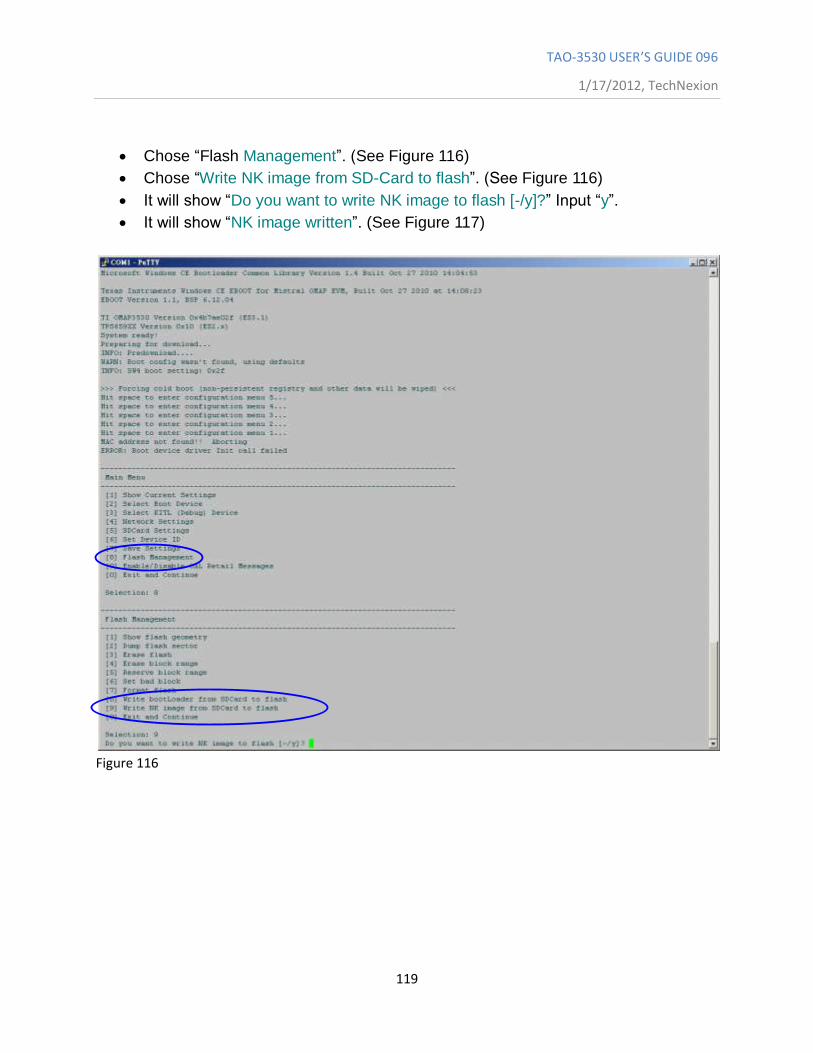
TAO-3530 USER’S GUIDE 096
1/17/2012, TechNexion
119
Chose “Flash Management”. (See Figure 116)
Chose “Write NK image from SD-Card to flash”. (See Figure 116)
It will show “Do you want to write NK image to flash [-/y]?” Input “y”.
It will show “NK image written”. (See Figure 117)
Figure 116
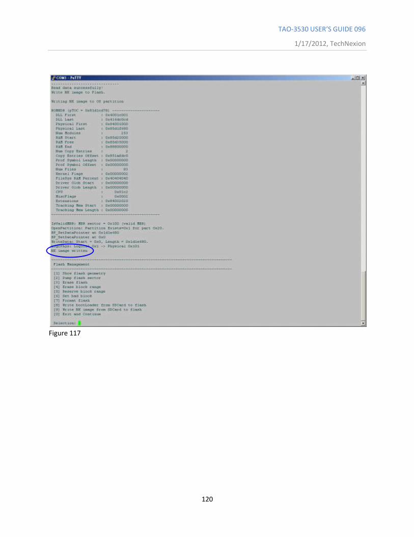
TAO-3530 USER’S GUIDE 096
1/17/2012, TechNexion
120
Figure 117
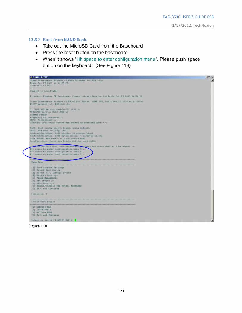
TAO-3530 USER’S GUIDE 096
1/17/2012, TechNexion
121
12.5.3 Boot from NAND flash.
Take out the MicroSD Card from the Baseboard
Press the reset button on the baseboard
When it shows “Hit space to enter configuration menu”. Please push space
button on the keyboard. (See Figure 118)
Figure 118
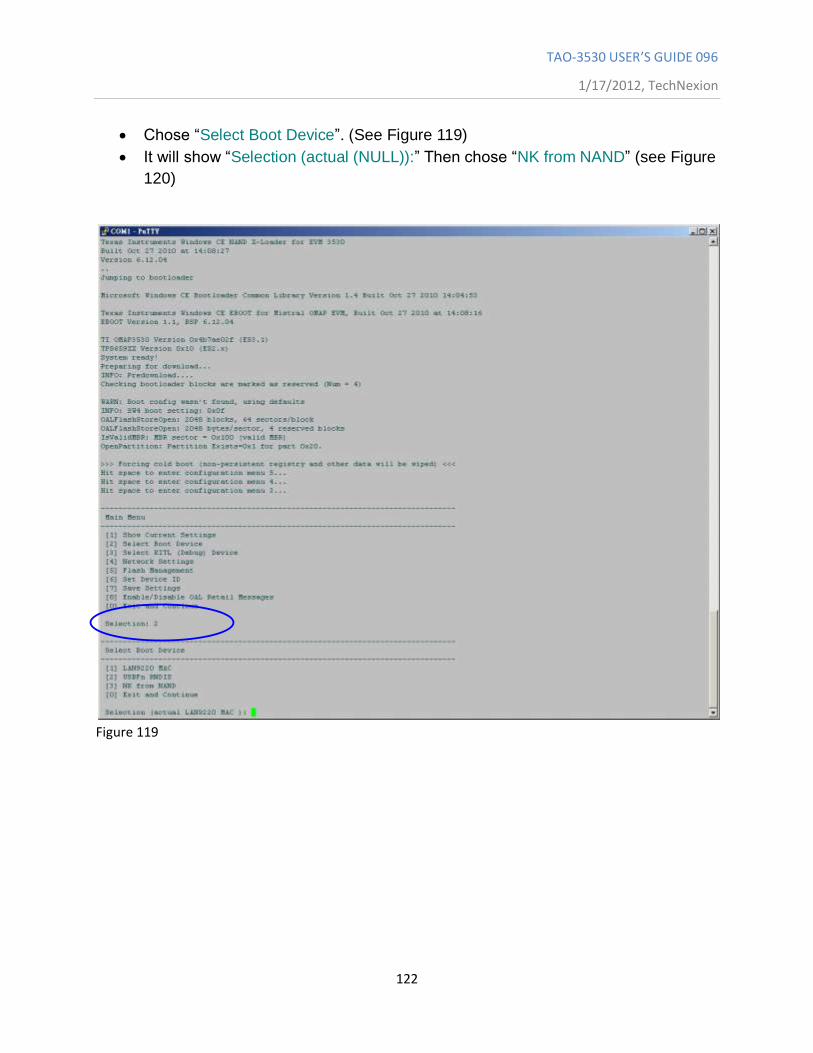
TAO-3530 USER’S GUIDE 096
1/17/2012, TechNexion
122
Chose “Select Boot Device”. (See Figure 119)
It will show “Selection (actual (NULL)):” Then chose “NK from NAND” (see Figure
120)
Figure 119
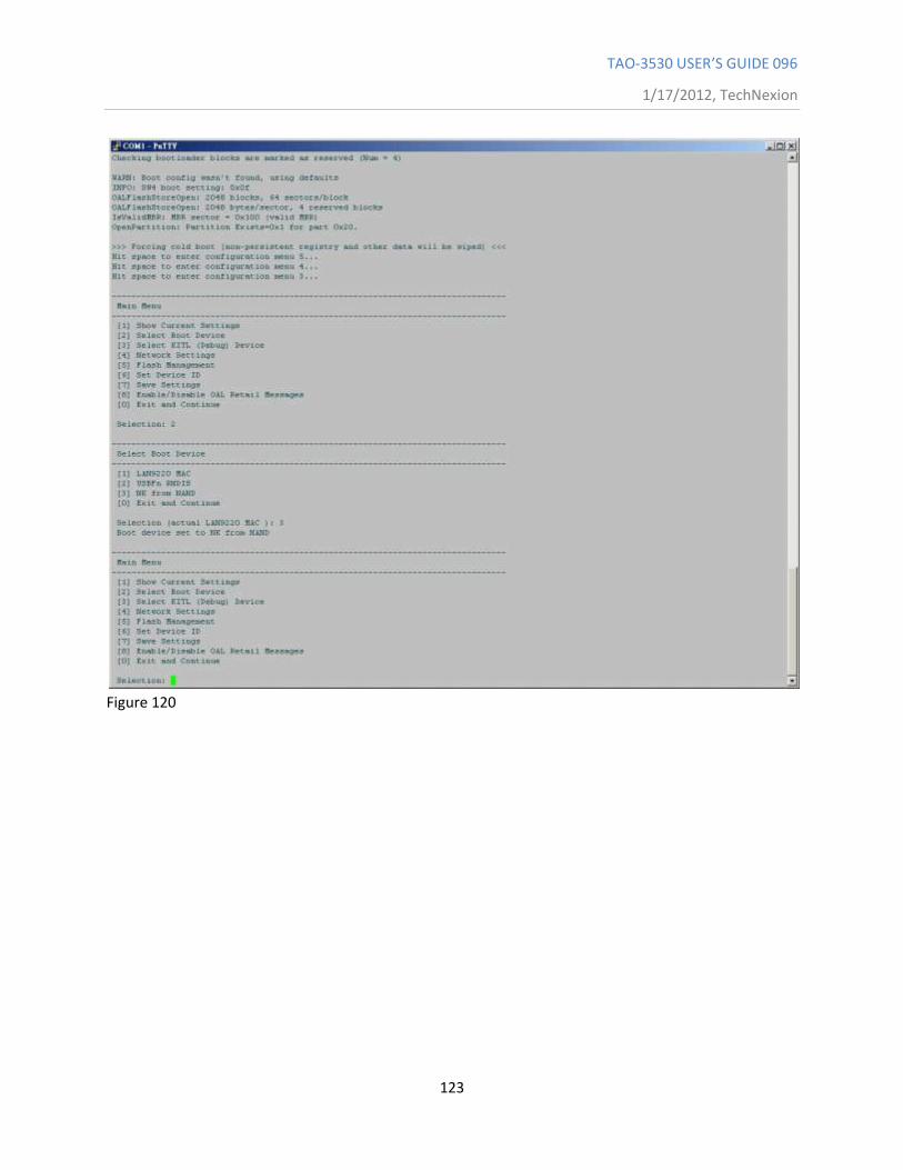
TAO-3530 USER’S GUIDE 096
1/17/2012, TechNexion
123
Figure 120
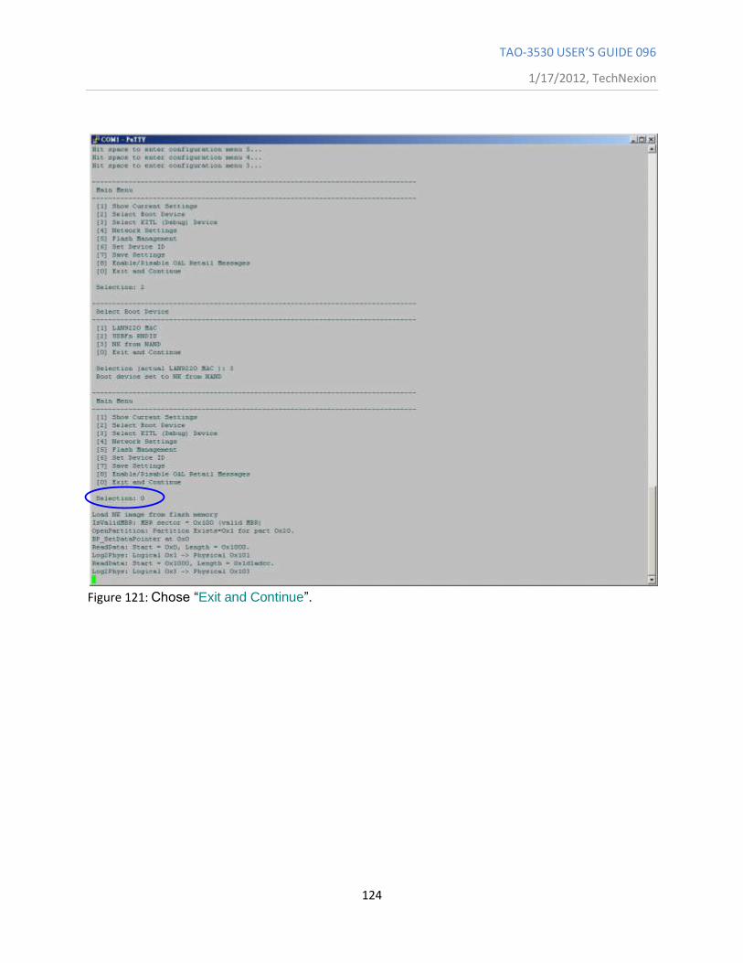
TAO-3530 USER’S GUIDE 096
1/17/2012, TechNexion
124
Figure 121: Chose “Exit and Continue”.
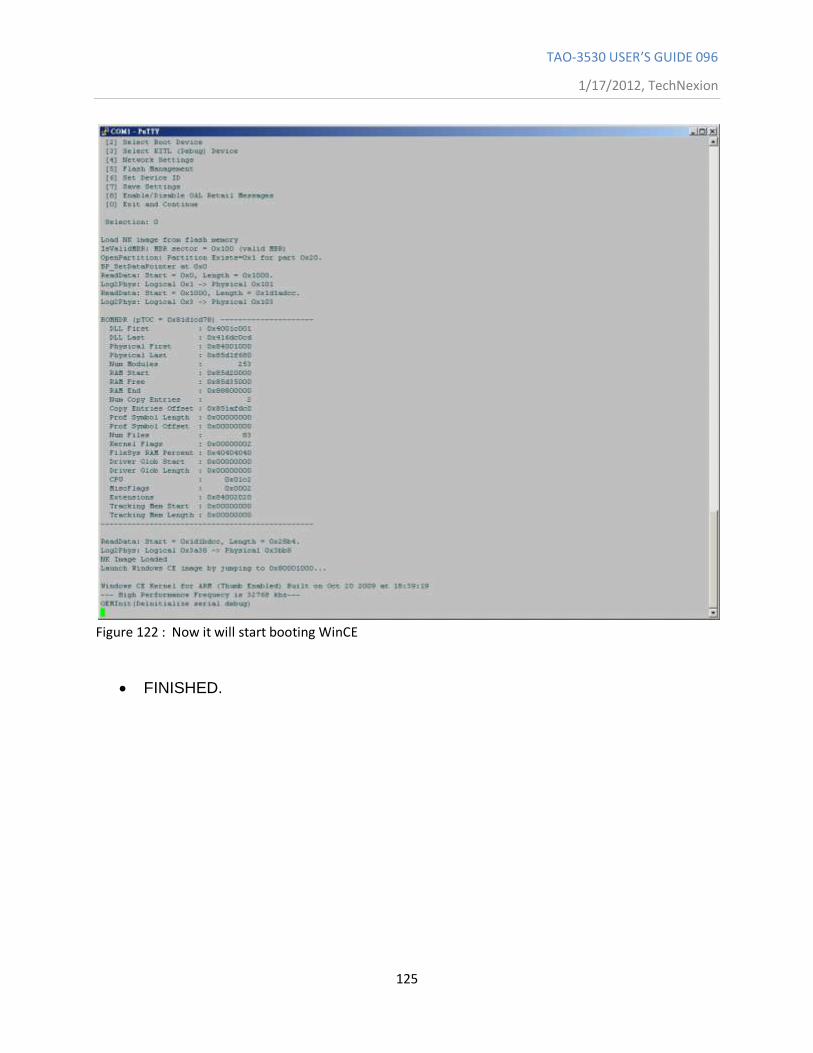
TAO-3530 USER’S GUIDE 096
1/17/2012, TechNexion
125
Figure 122 : Now it will start booting WinCE
FINISHED.
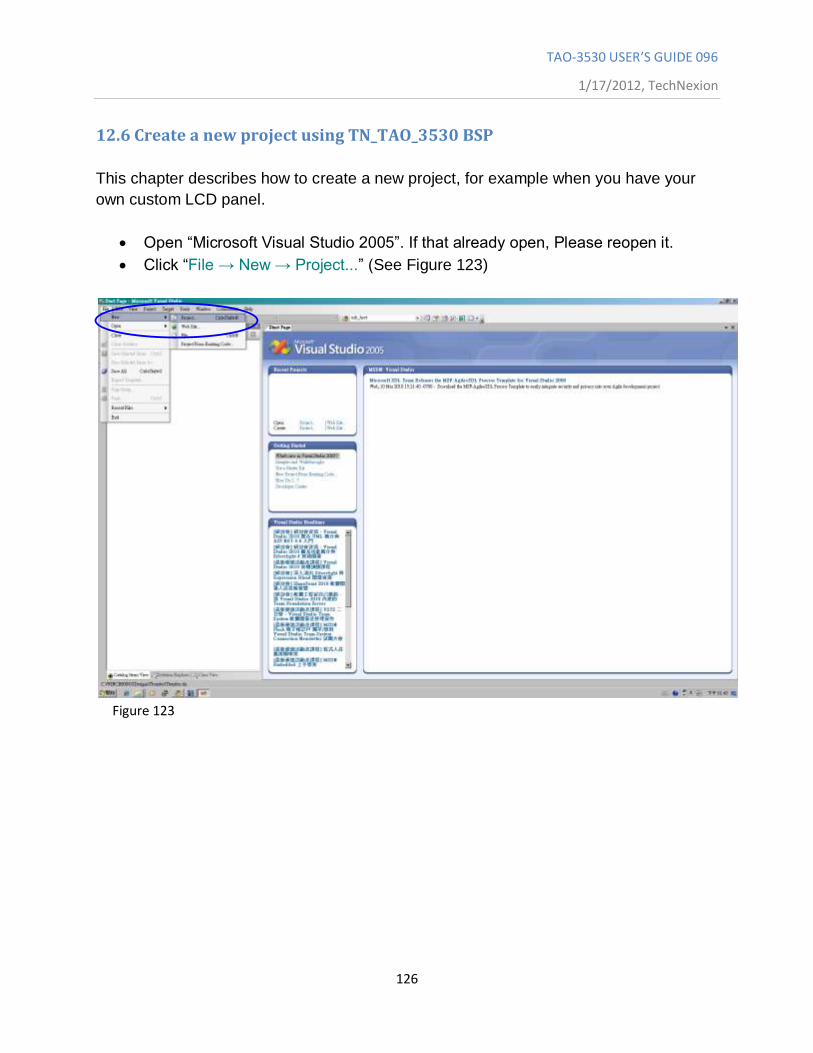
TAO-3530 USER’S GUIDE 096
1/17/2012, TechNexion
126
12.6 Create a new project using TN_TAO_3530 BSP
This chapter describes how to create a new project, for example when you have your
own custom LCD panel.
Open “Microsoft Visual Studio 2005”. If that already open, Please reopen it.
Click “File → New → Project...” (See Figure 123)
Figure 123
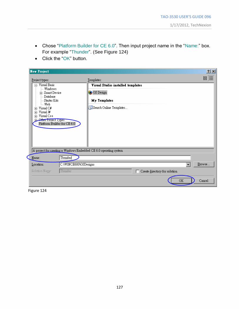
TAO-3530 USER’S GUIDE 096
1/17/2012, TechNexion
127
Chose “Platform Builder for CE 6.0”. Then input project name in the “Name:” box.
For example “Thunder”. (See Figure 124)
Click the “OK” button.
Figure 124
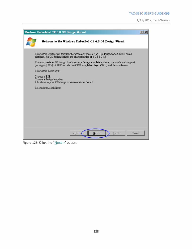
TAO-3530 USER’S GUIDE 096
1/17/2012, TechNexion
128
Figure 125: Click the “Next >” button.
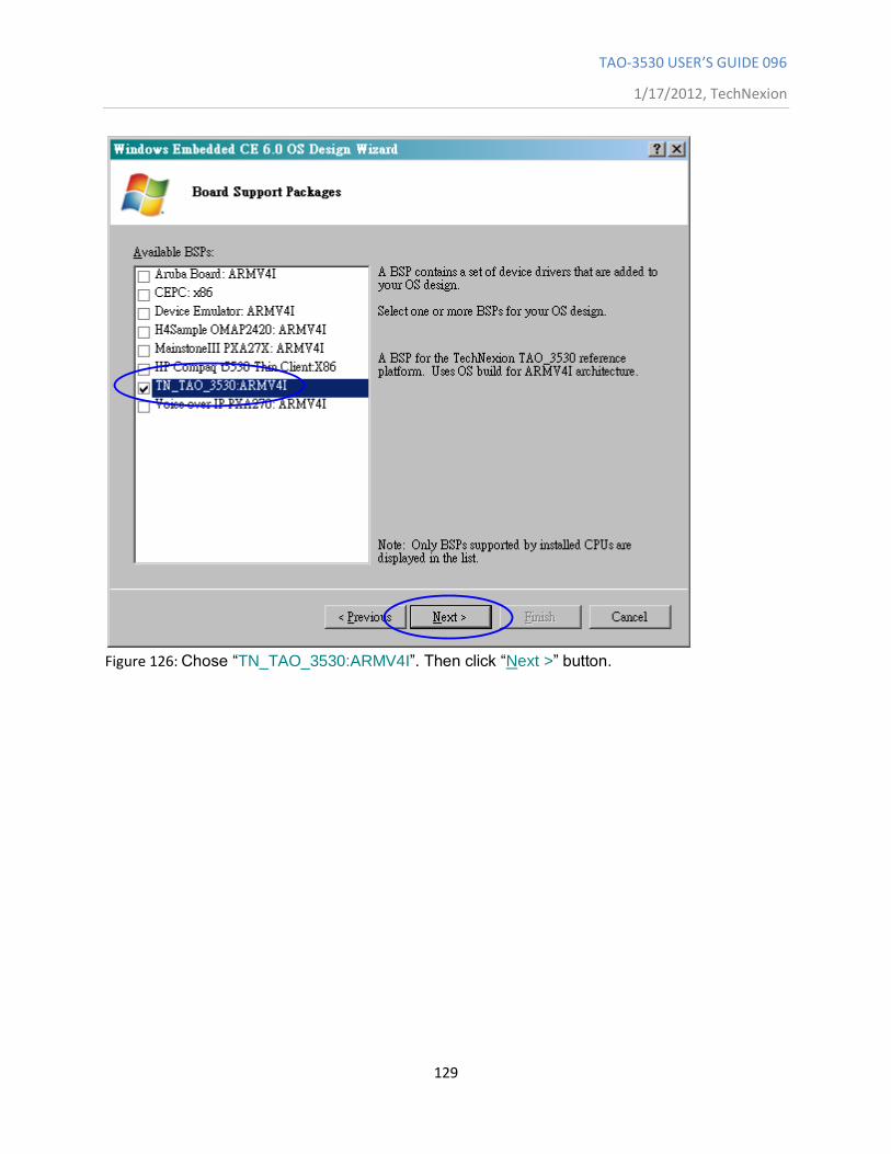
TAO-3530 USER’S GUIDE 096
1/17/2012, TechNexion
129
Figure 126: Chose “TN_TAO_3530:ARMV4I”. Then click “Next >” button.
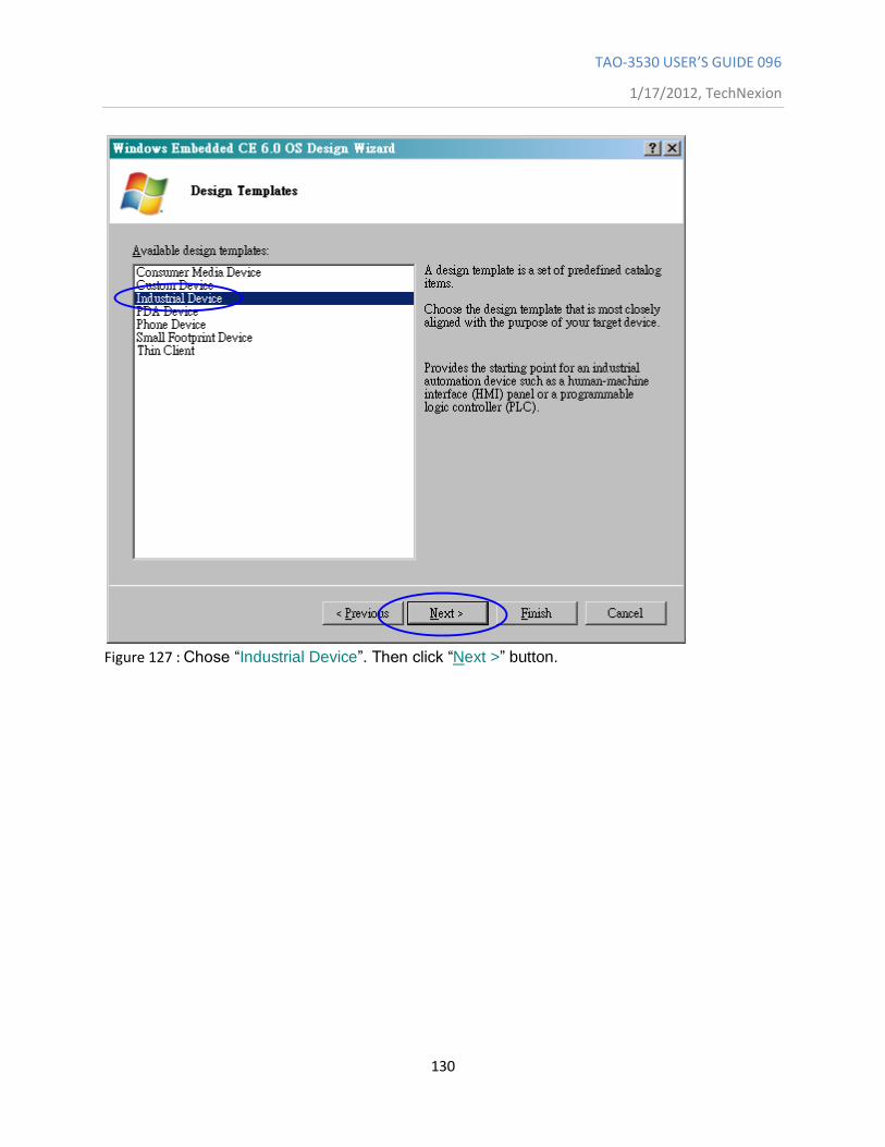
TAO-3530 USER’S GUIDE 096
1/17/2012, TechNexion
130
Figure 127 : Chose “Industrial Device”. Then click “Next >” button.
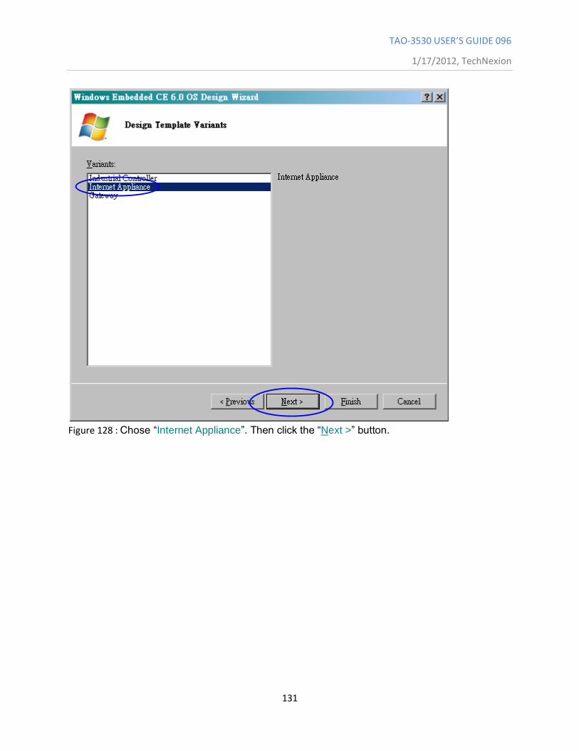
TAO-3530 USER’S GUIDE 096
1/17/2012, TechNexion
131
Figure 128 : Chose “Internet Appliance”. Then click the “Next >” button.
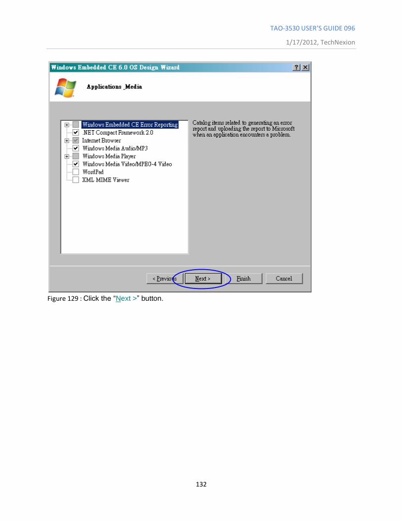
TAO-3530 USER’S GUIDE 096
1/17/2012, TechNexion
132
Figure 129 : Click the “Next >” button.
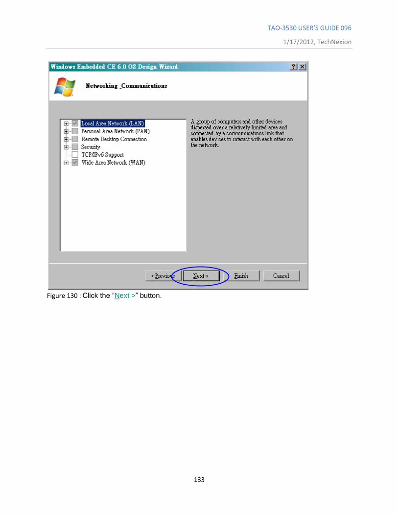
TAO-3530 USER’S GUIDE 096
1/17/2012, TechNexion
133
Figure 130 : Click the “Next >” button.
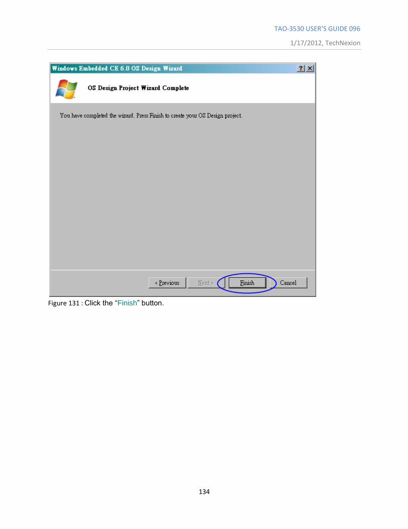
TAO-3530 USER’S GUIDE 096
1/17/2012, TechNexion
134
Figure 131 : Click the “Finish” button.
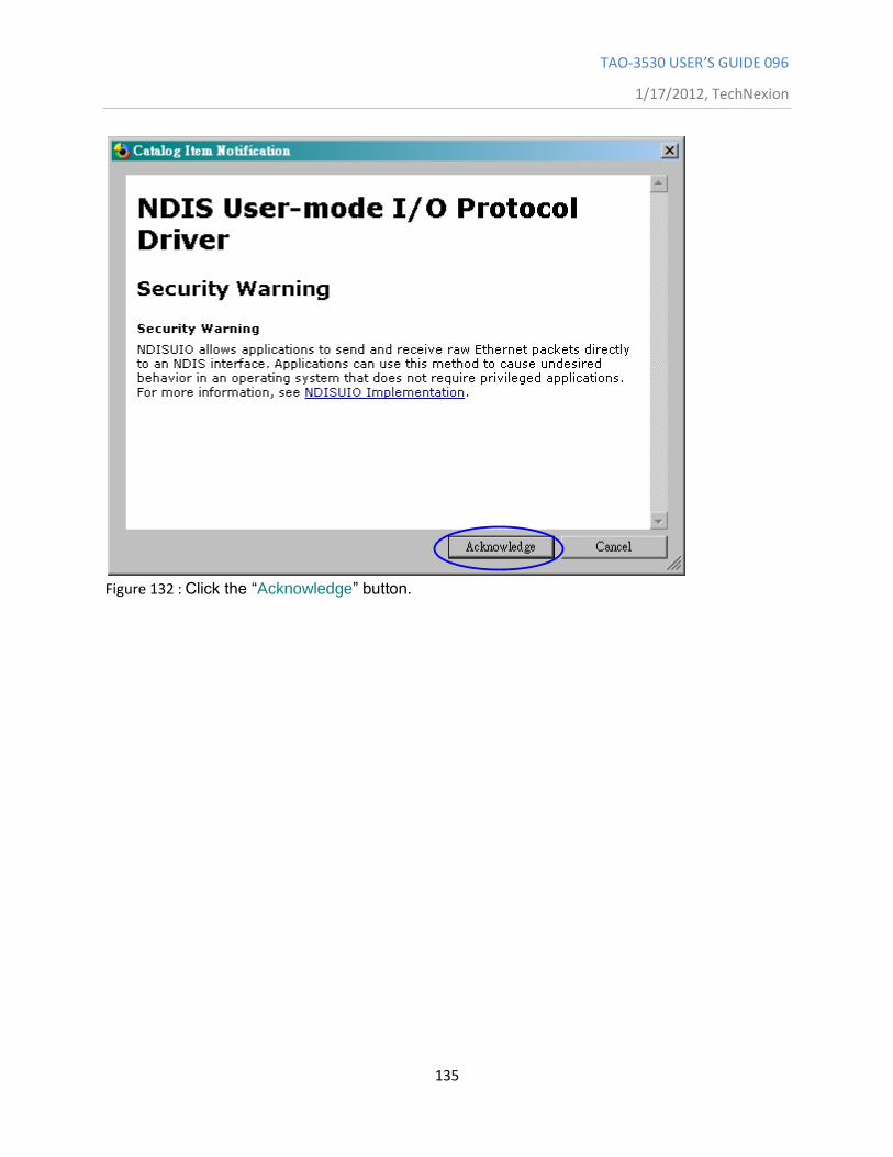
TAO-3530 USER’S GUIDE 096
1/17/2012, TechNexion
135
Figure 132 : Click the “Acknowledge” button.
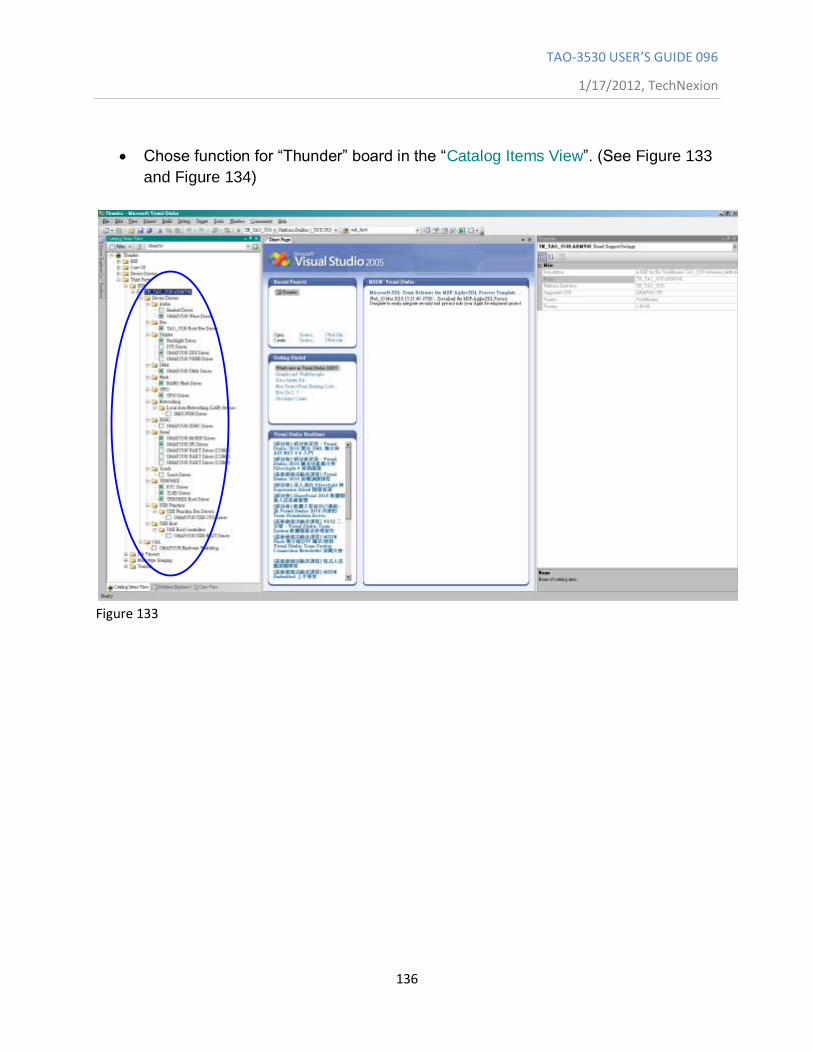
TAO-3530 USER’S GUIDE 096
1/17/2012, TechNexion
136
Chose function for “Thunder” board in the “Catalog Items View”. (See Figure 133
and Figure 134)
Figure 133
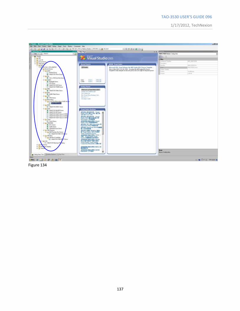
TAO-3530 USER’S GUIDE 096
1/17/2012, TechNexion
137
Figure 134
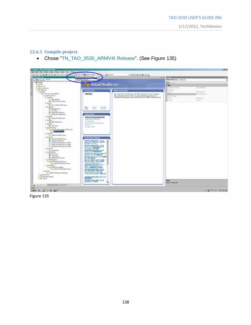
TAO-3530 USER’S GUIDE 096
1/17/2012, TechNexion
138
12.6.1 Compile project.
Chose “TN_TAO_3530_ARMV4I Release”. (See Figure 135)
Figure 135
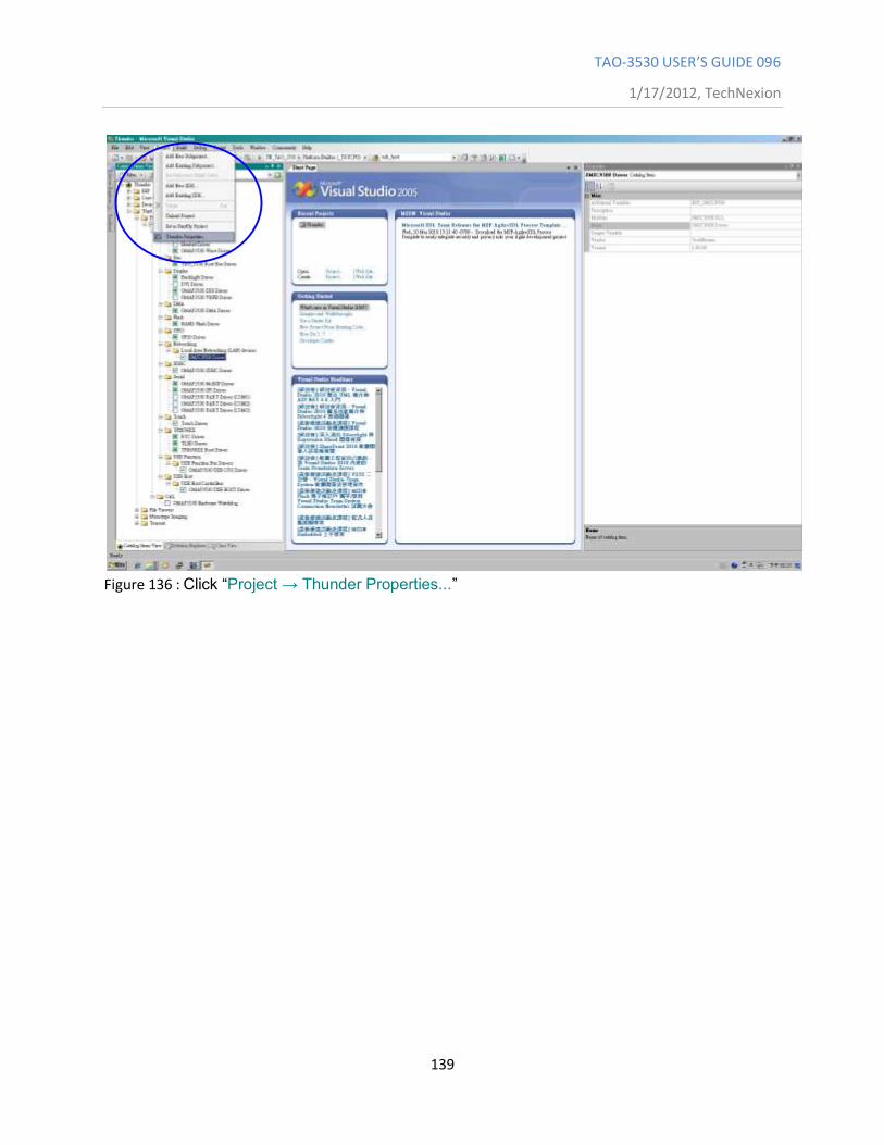
TAO-3530 USER’S GUIDE 096
1/17/2012, TechNexion
139
Figure 136 : Click “Project → Thunder Properties...”
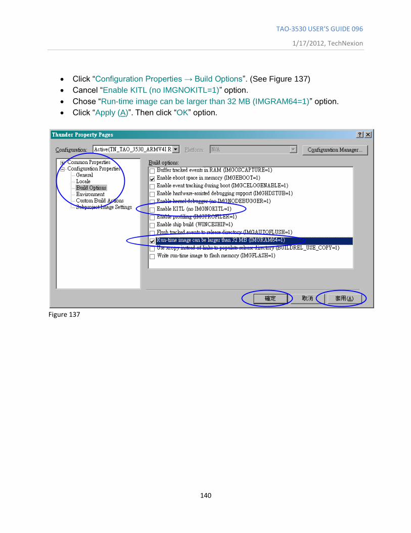
TAO-3530 USER’S GUIDE 096
1/17/2012, TechNexion
140
Click “Configuration Properties → Build Options”. (See Figure 137)
Cancel “Enable KITL (no IMGNOKITL=1)” option.
Chose “Run-time image can be larger than 32 MB (IMGRAM64=1)” option.
Click “Apply (A)”. Then click “OK” option.
Figure 137

TAO-3530 USER’S GUIDE 096
1/17/2012, TechNexion
141
Figure 138 : Click “Build → Advanced Build Commands → Sysgen”.
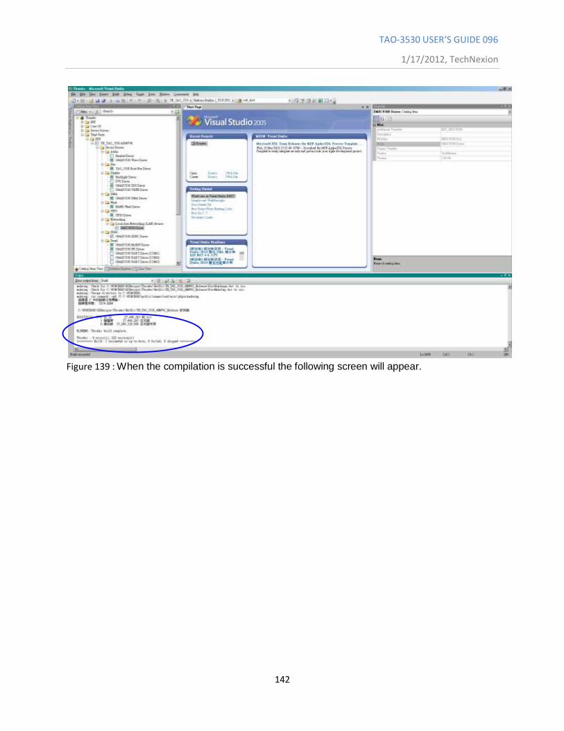
TAO-3530 USER’S GUIDE 096
1/17/2012, TechNexion
142
Figure 139 : When the compilation is successful the following screen will appear.
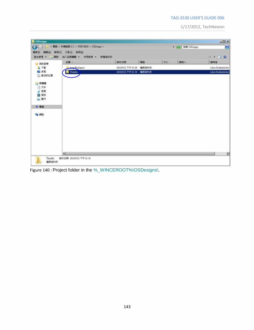
TAO-3530 USER’S GUIDE 096
1/17/2012, TechNexion
143
Figure 140 : Project folder in the %_WINCEROOT%\OSDesigns\.
TAO-3530 USER’S GUIDE 096
1/17/2012, TechNexion
144
12.7 How to change the logo that you see during boot up
During boot up you will see a TechNexion logo or a screen with four colored squares. As
shown in 12.5.2 you can choose between “fldr.raw” and “fldr-logo.raw”. Fldr.raw will,
during boot up, show a screen divided in four squares with different colors. Fldrlogo.raw
will, during boot up, show a dark screen with a TechNexion logo. This section will
describe how to make your own logo to appear.
12.7.1 Preparing the BMP
You will need to prepare a BMP with your logo. However the logo needs to be
flipped vertical (see Figure 141)
Figure 141
This can be done with for instance Photoshop (Use: edit \ transform \ flip vertical)
Place the flipped BMP at the following directory:
C:\WINCE600\PLATFORM\TN_TAO_3530\FILES
The final result on your display will be as below (see Figure 142)
Figure 142
12.7.2 Change the makefile.inc
Open a text editor (for instance Notepad)
Open makefile.inc, which is in the directory:
C:\WINCE600\PLATFORM\TN_TAO_3530\SRC\BOOT\XLDR\NAND
Change the orange part in the following line with the name of your BMP:
Copy /b $(_TGT)\TIEVM3530-nand.raw + $(_FILES)\TechNexion.bmp
$(_TGT)\TIEVM3530-nand-logo.raw
Save makefile.inc in the same directory
12.7.3 Calculate the needed blocks
You need to calculate the needed blocks in your NAND Flash to store the logo.
For instance the TechNexion logo is 292x39 pixels and in RGB color(x3), that
means it is using: 292x39x3=34164 bytes.
This is 34164/1024= 33.36kB
The NAND Flash blocks are 128kB in size so it will fit in 1 block
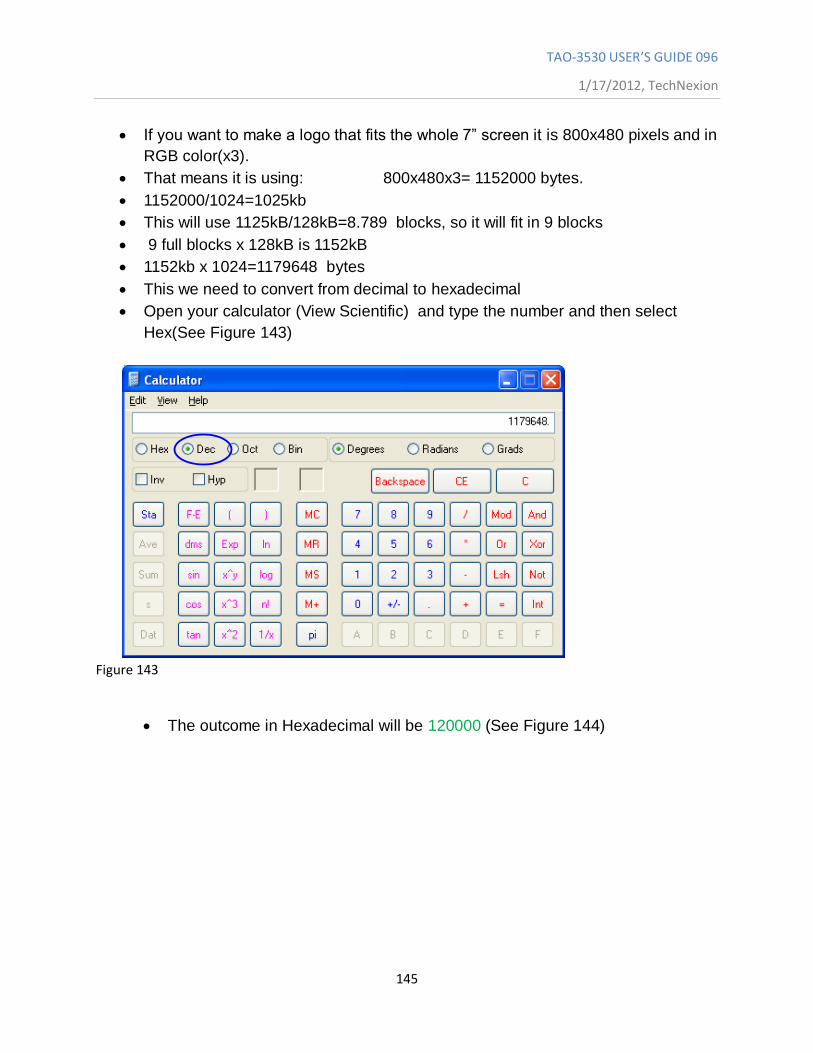
TAO-3530 USER’S GUIDE 096
1/17/2012, TechNexion
145
If you want to make a logo that fits the whole 7” screen it is 800x480 pixels and in
RGB color(x3).
That means it is using: 800x480x3= 1152000 bytes.
1152000/1024=1025kb
This will use 1125kB/128kB=8.789 blocks, so it will fit in 9 blocks
9 full blocks x 128kB is 1152kB
1152kb x 1024=1179648 bytes
This we need to convert from decimal to hexadecimal
Open your calculator (View Scientific) and type the number and then select
Hex(See Figure 143)
Figure 143
The outcome in Hexadecimal will be 120000 (See Figure 144)
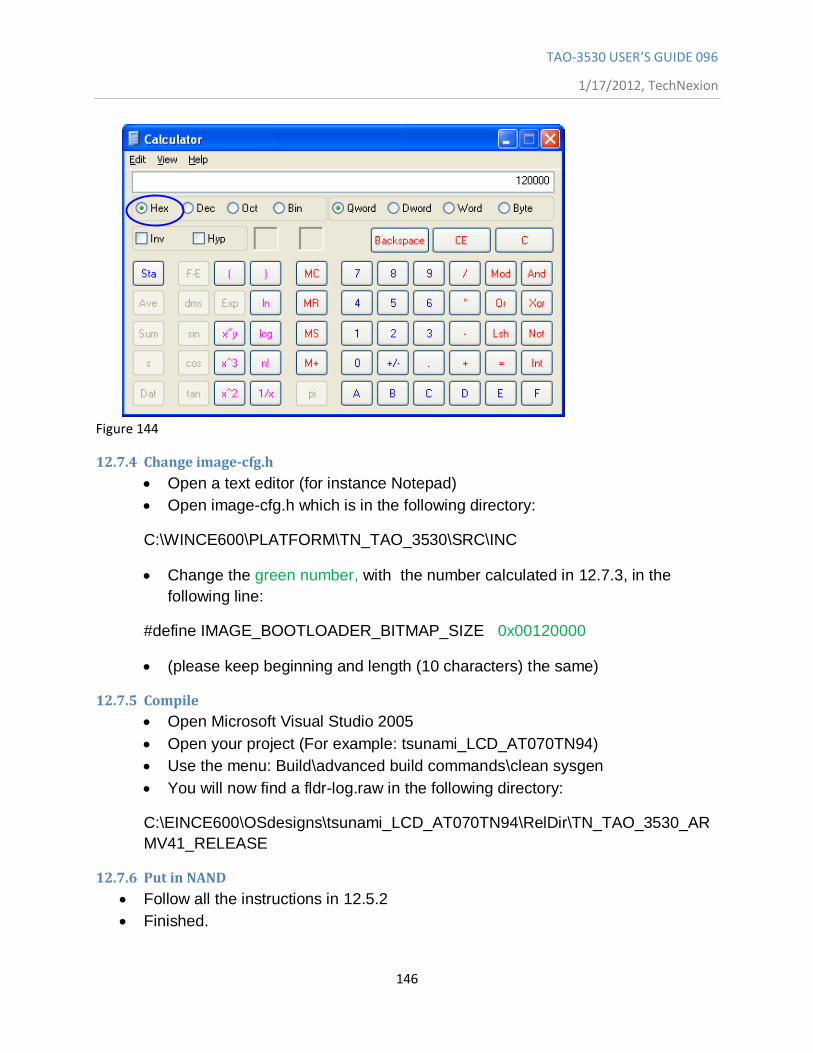
TAO-3530 USER’S GUIDE 096
1/17/2012, TechNexion
146
Figure 144
12.7.4 Change image-cfg.h
Open a text editor (for instance Notepad)
Open image-cfg.h which is in the following directory:
C:\WINCE600\PLATFORM\TN_TAO_3530\SRC\INC
Change the green number, with the number calculated in 12.7.3, in the
following line:
#define IMAGE_BOOTLOADER_BITMAP_SIZE 0x00120000
(please keep beginning and length (10 characters) the same)
12.7.5 Compile
Open Microsoft Visual Studio 2005
Open your project (For example: tsunami_LCD_AT070TN94)
Use the menu: Build\advanced build commands\clean sysgen
You will now find a fldr-log.raw in the following directory:
C:\EINCE600\OSdesigns\tsunami_LCD_AT070TN94\RelDir\TN_TAO_3530_AR
MV41_RELEASE
12.7.6 Put in NAND
Follow all the instructions in 12.5.2
Finished.
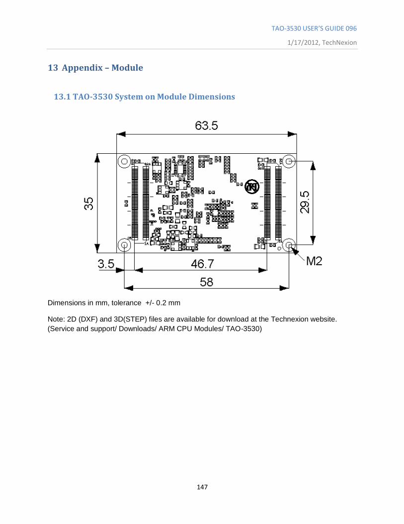
TAO-3530 USER’S GUIDE 096
1/17/2012, TechNexion
147
13 Appendix – Module
13.1 TAO-3530 System on Module Dimensions
Dimensions in mm, tolerance +/- 0.2 mm
Note: 2D (DXF) and 3D(STEP) files are available for download at the Technexion website.
(Service and support/ Downloads/ ARM CPU Modules/ TAO-3530)
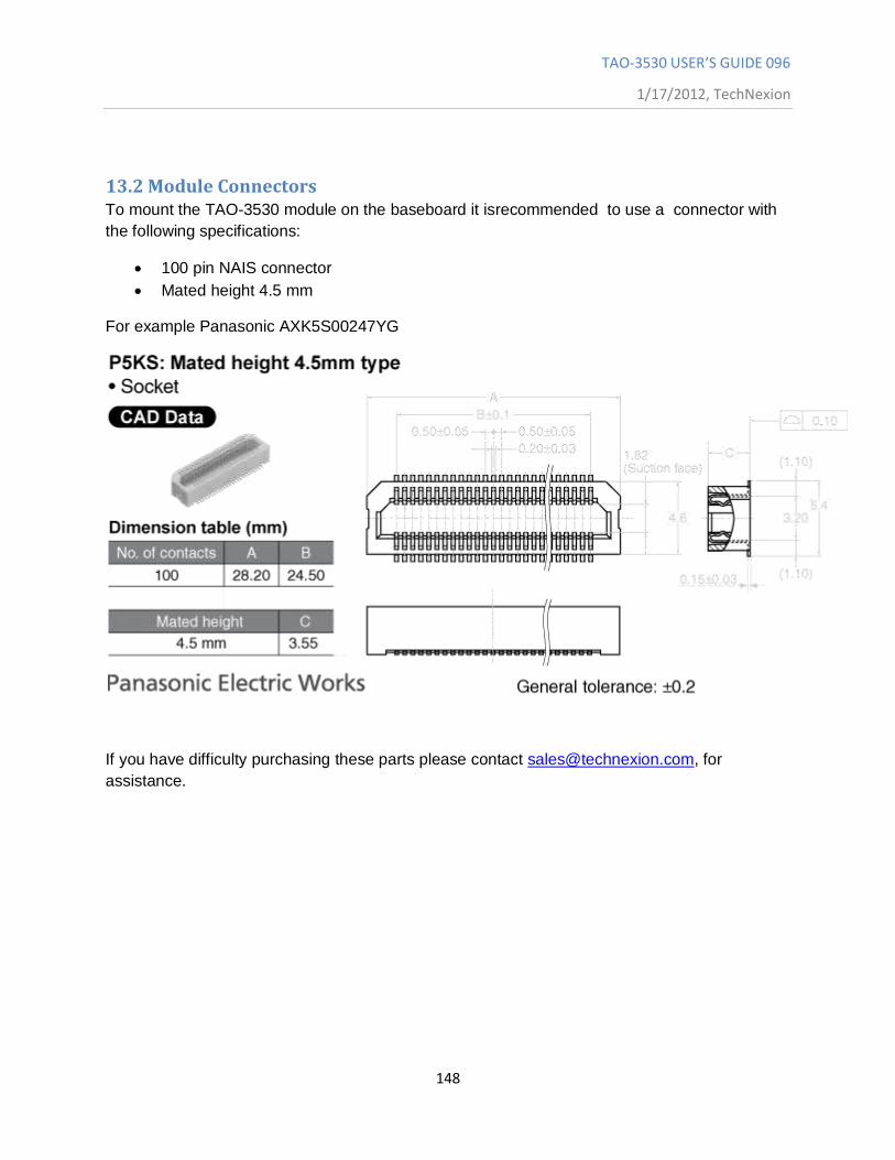
TAO-3530 USER’S GUIDE 096
1/17/2012, TechNexion
148
13.2 Module Connectors To mount the TAO-3530 module on the baseboard it isrecommended to use a connector with
the following specifications:
100 pin NAIS connector
Mated height 4.5 mm
For example Panasonic AXK5S00247YG
If you have difficulty purchasing these parts please contact [email protected], for
assistance.
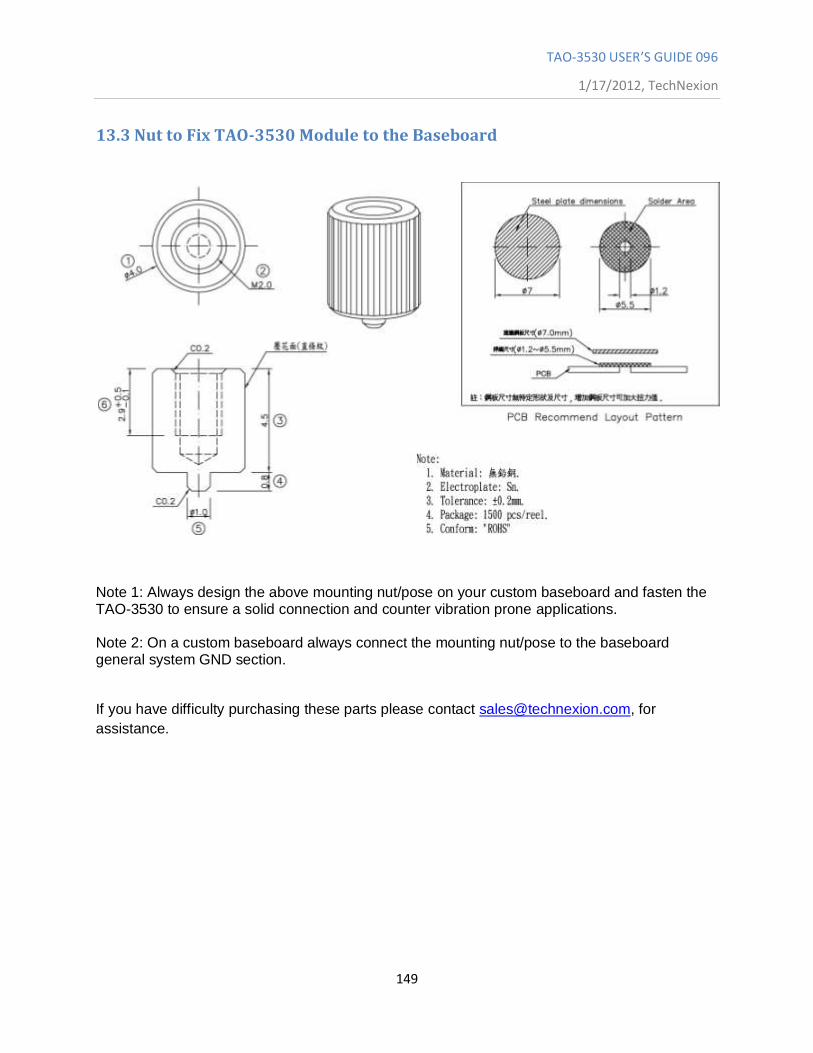
TAO-3530 USER’S GUIDE 096
1/17/2012, TechNexion
149
13.3 Nut to Fix TAO-3530 Module to the Baseboard
Note 1: Always design the above mounting nut/pose on your custom baseboard and fasten the TAO-3530 to ensure a solid connection and counter vibration prone applications. Note 2: On a custom baseboard always connect the mounting nut/pose to the baseboard general system GND section.
If you have difficulty purchasing these parts please contact [email protected], for
assistance.
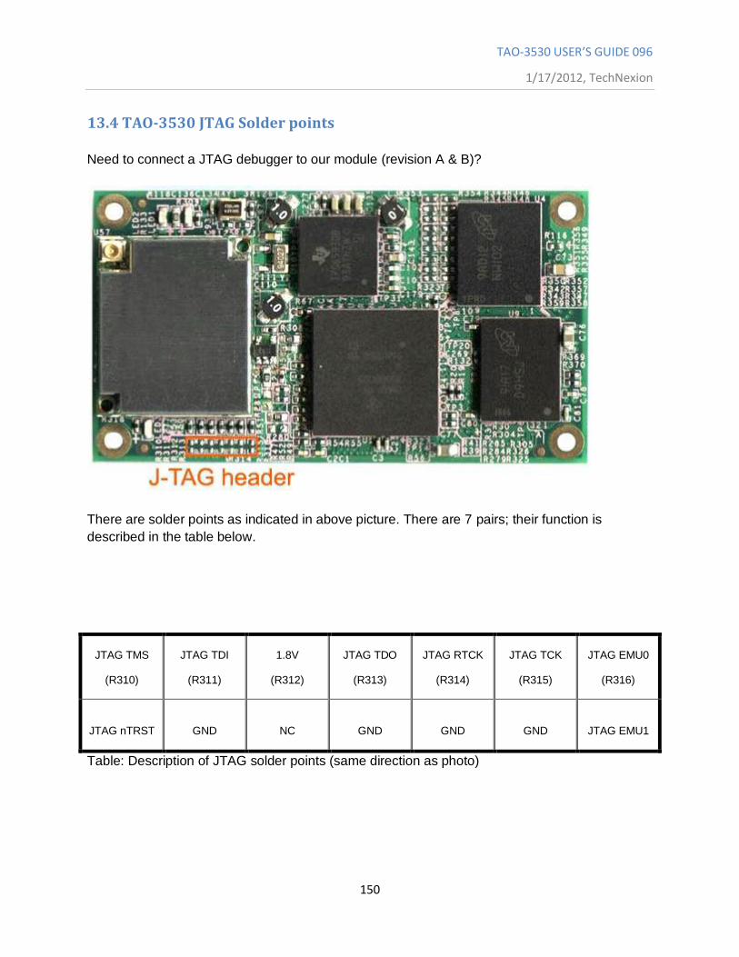
TAO-3530 USER’S GUIDE 096
1/17/2012, TechNexion
150
13.4 TAO-3530 JTAG Solder points
Need to connect a JTAG debugger to our module (revision A & B)?
There are solder points as indicated in above picture. There are 7 pairs; their function is
described in the table below.
JTAG TMS
(R310)
JTAG TDI
(R311)
1.8V
(R312)
JTAG TDO
(R313)
JTAG RTCK
(R314)
JTAG TCK
(R315)
JTAG EMU0
(R316)
JTAG nTRST
GND
NC
GND
GND
GND
JTAG EMU1
Table: Description of JTAG solder points (same direction as photo)
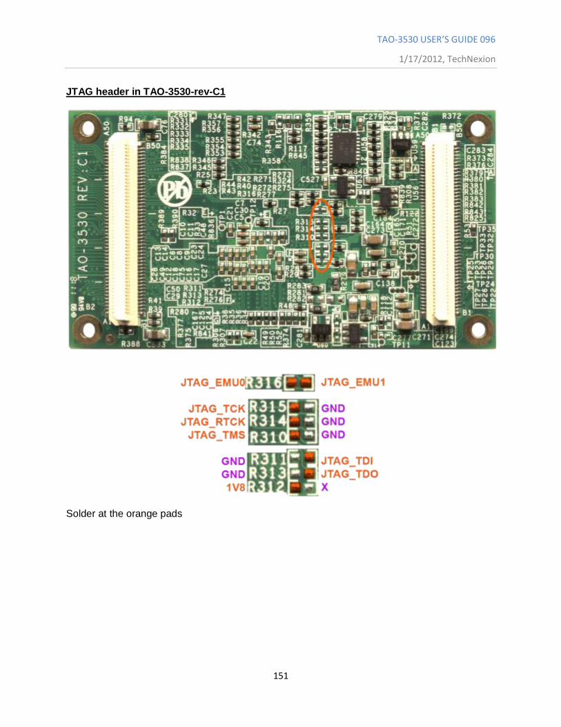
TAO-3530 USER’S GUIDE 096
1/17/2012, TechNexion
151
JTAG header in TAO-3530-rev-C1
Solder at the orange pads
TAO-3530 USER’S GUIDE 096
1/17/2012, TechNexion
152
14 Appendix - Schematics
14.1 Inferno baseboard schematics
If you are designing your own baseboard then please contact [email protected] for clear design files
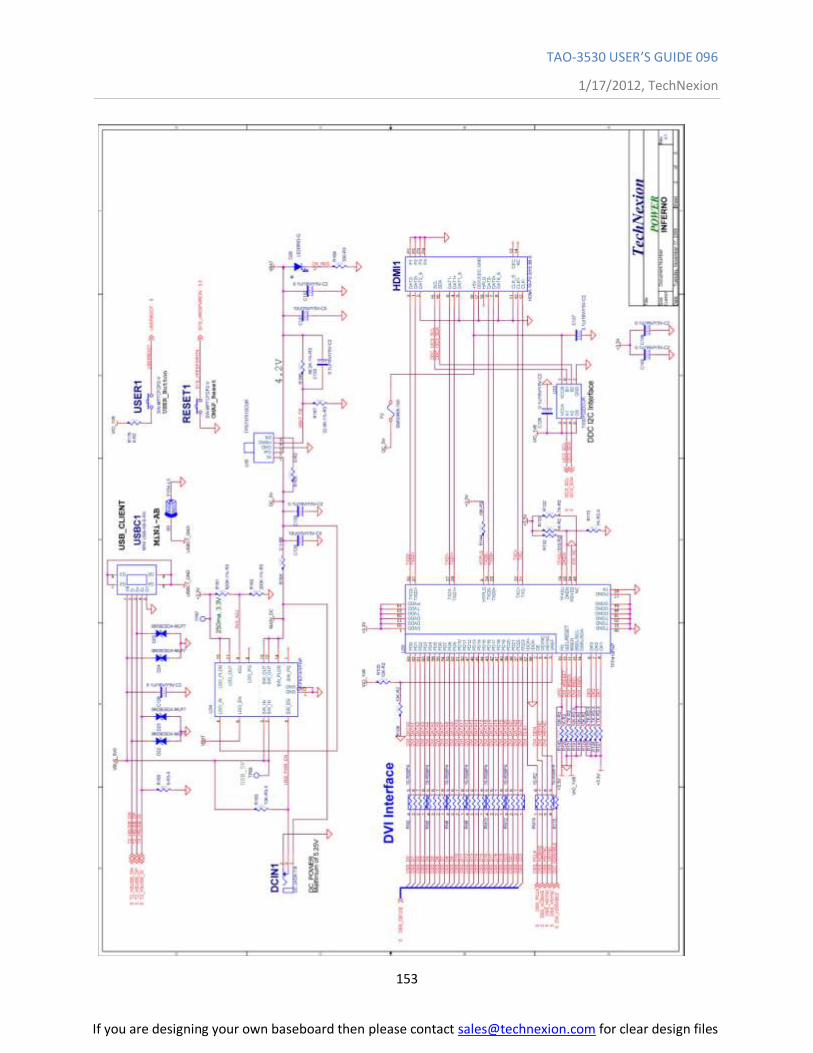
TAO-3530 USER’S GUIDE 096
1/17/2012, TechNexion
153
If you are designing your own baseboard then please contact [email protected] for clear design files
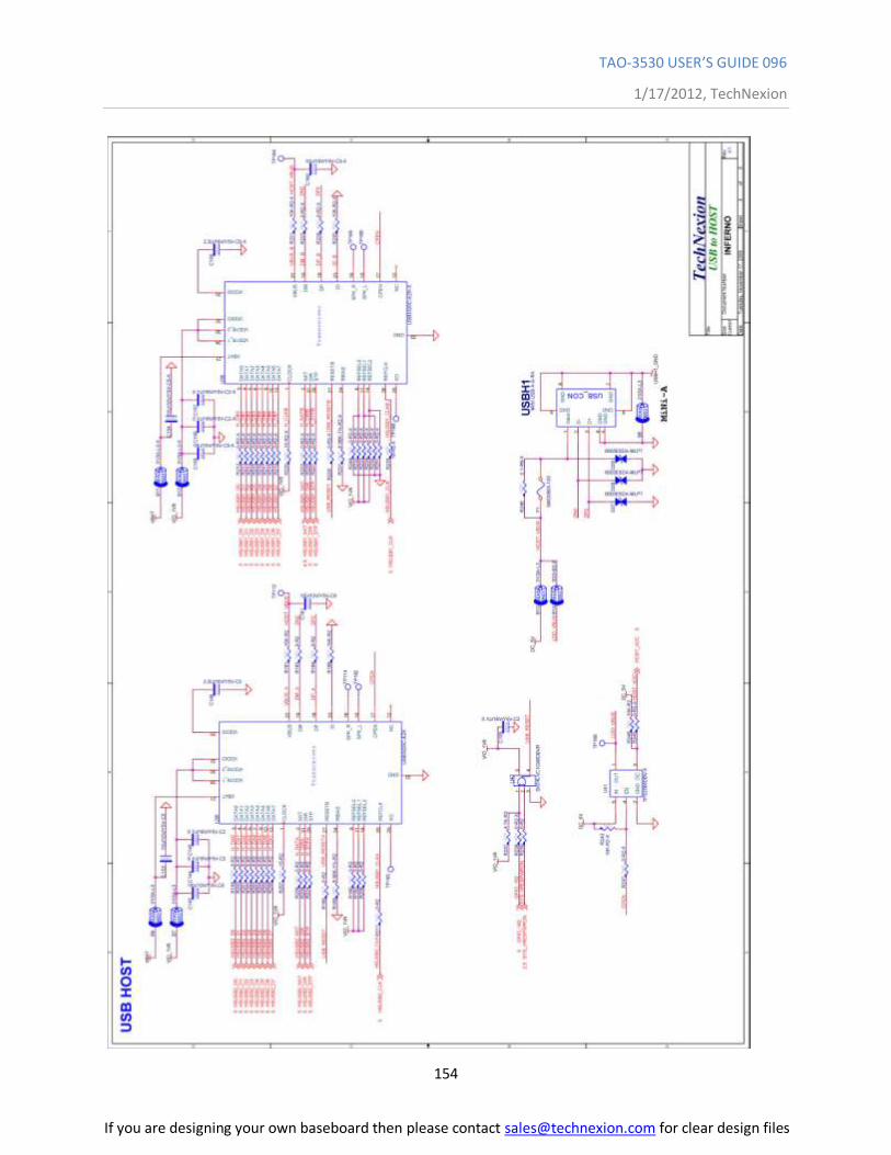
TAO-3530 USER’S GUIDE 096
1/17/2012, TechNexion
154
If you are designing your own baseboard then please contact [email protected] for clear design files
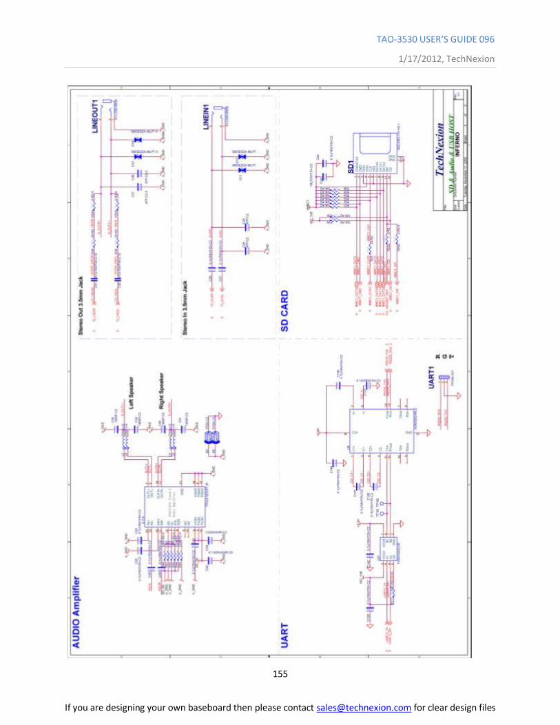
TAO-3530 USER’S GUIDE 096
1/17/2012, TechNexion
155
If you are designing your own baseboard then please contact [email protected] for clear design files
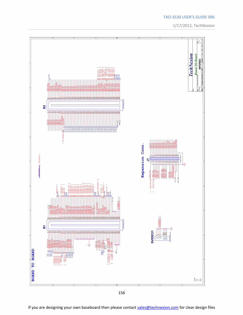
TAO-3530 USER’S GUIDE 096
1/17/2012, TechNexion
156
If you are designing your own baseboard then please contact [email protected] for clear design files
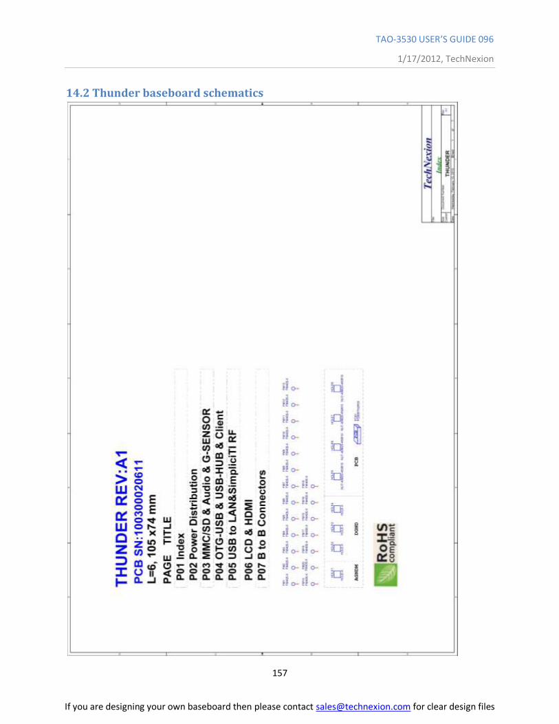
TAO-3530 USER’S GUIDE 096
1/17/2012, TechNexion
157
14.2 Thunder baseboard schematics
If you are designing your own baseboard then please contact [email protected] for clear design files
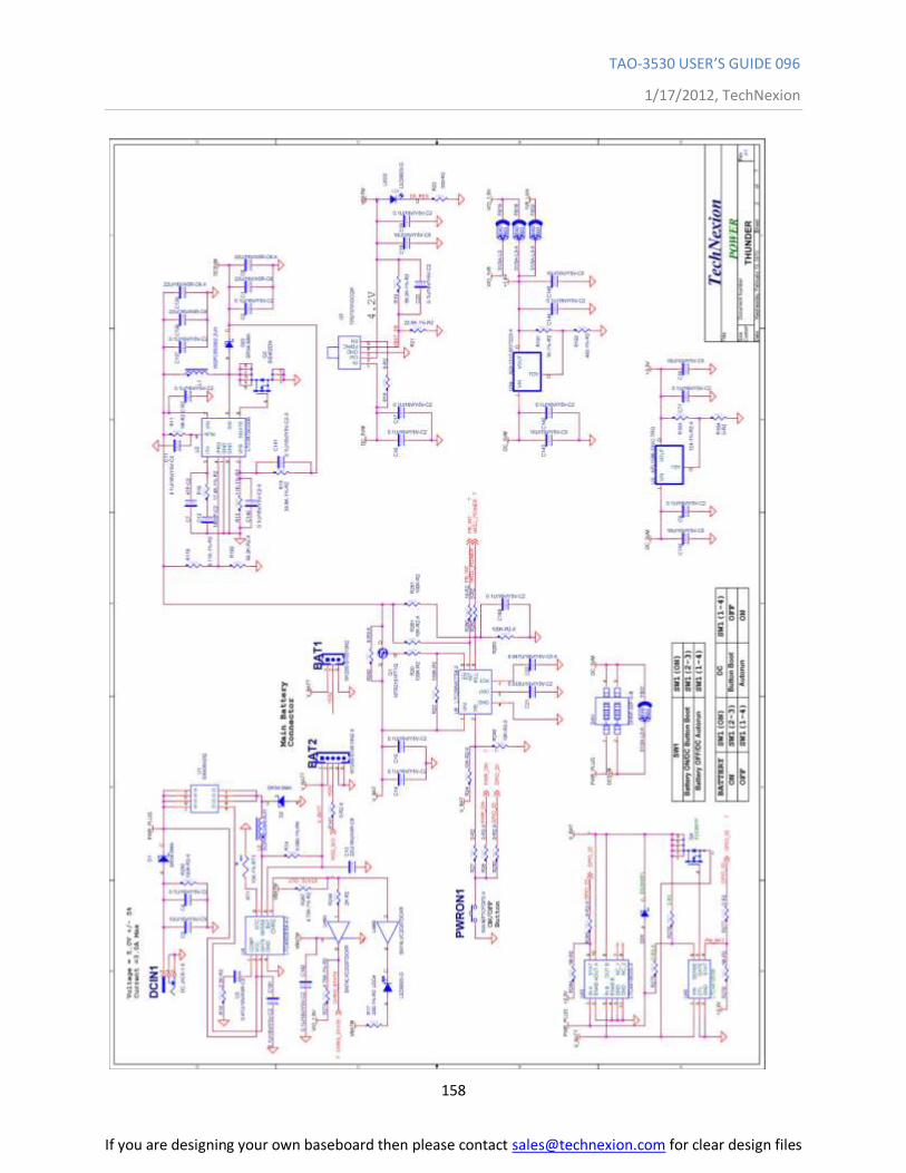
TAO-3530 USER’S GUIDE 096
1/17/2012, TechNexion
158
If you are designing your own baseboard then please contact [email protected] for clear design files
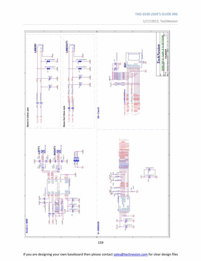
TAO-3530 USER’S GUIDE 096
1/17/2012, TechNexion
159
If you are designing your own baseboard then please contact [email protected] for clear design files
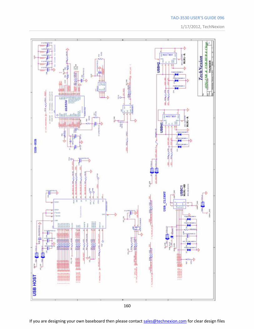
TAO-3530 USER’S GUIDE 096
1/17/2012, TechNexion
160
If you are designing your own baseboard then please contact [email protected] for clear design files
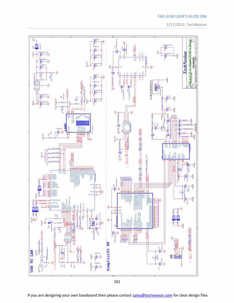
TAO-3530 USER’S GUIDE 096
1/17/2012, TechNexion
161
If you are designing your own baseboard then please contact [email protected] for clear design files
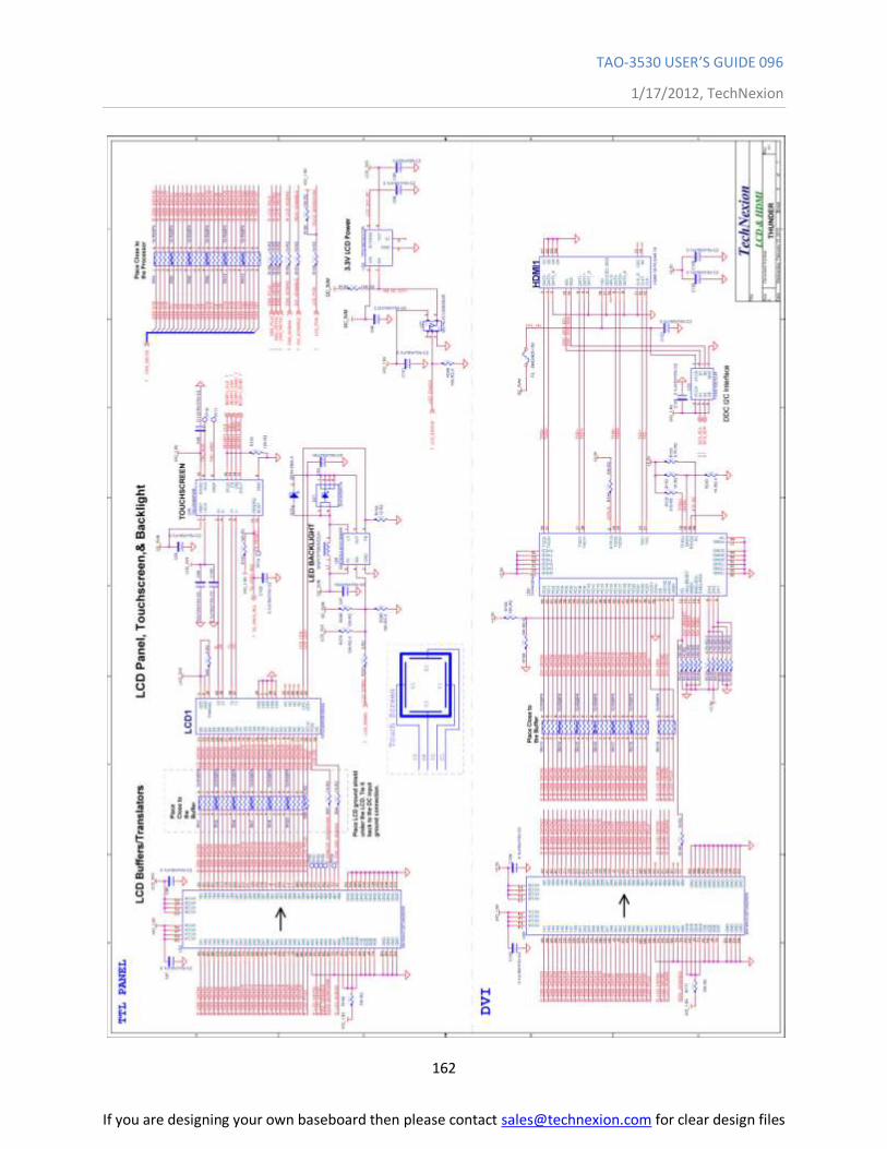
TAO-3530 USER’S GUIDE 096
1/17/2012, TechNexion
162
If you are designing your own baseboard then please contact [email protected] for clear design files
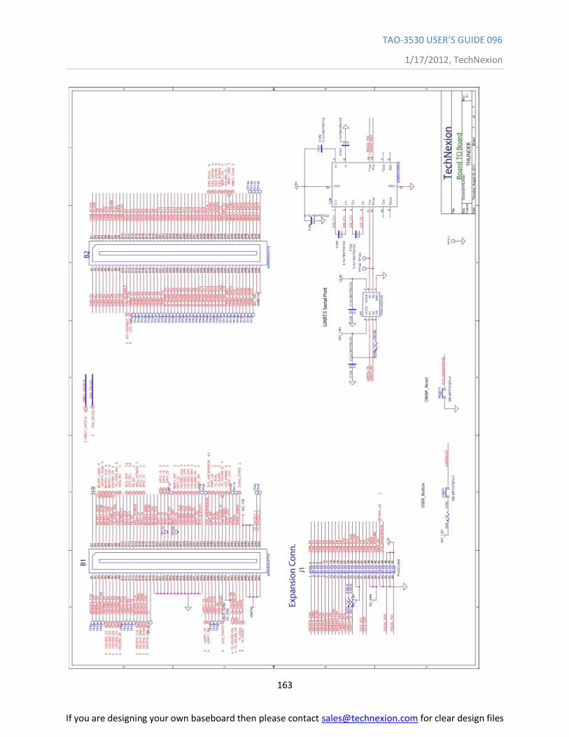
TAO-3530 USER’S GUIDE 096
1/17/2012, TechNexion
163
If you are designing your own baseboard then please contact [email protected] for clear design files
TAO-3530 USER’S GUIDE 096
1/17/2012, TechNexion
164
14.3 Tsunami baseboard schematics
If you are designing your own baseboard then please contact [email protected] for clear design files
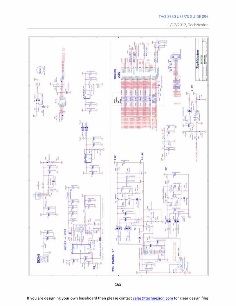
TAO-3530 USER’S GUIDE 096
1/17/2012, TechNexion
165
If you are designing your own baseboard then please contact [email protected] for clear design files
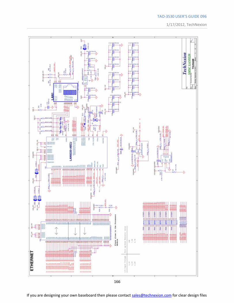
TAO-3530 USER’S GUIDE 096
1/17/2012, TechNexion
166
If you are designing your own baseboard then please contact [email protected] for clear design files
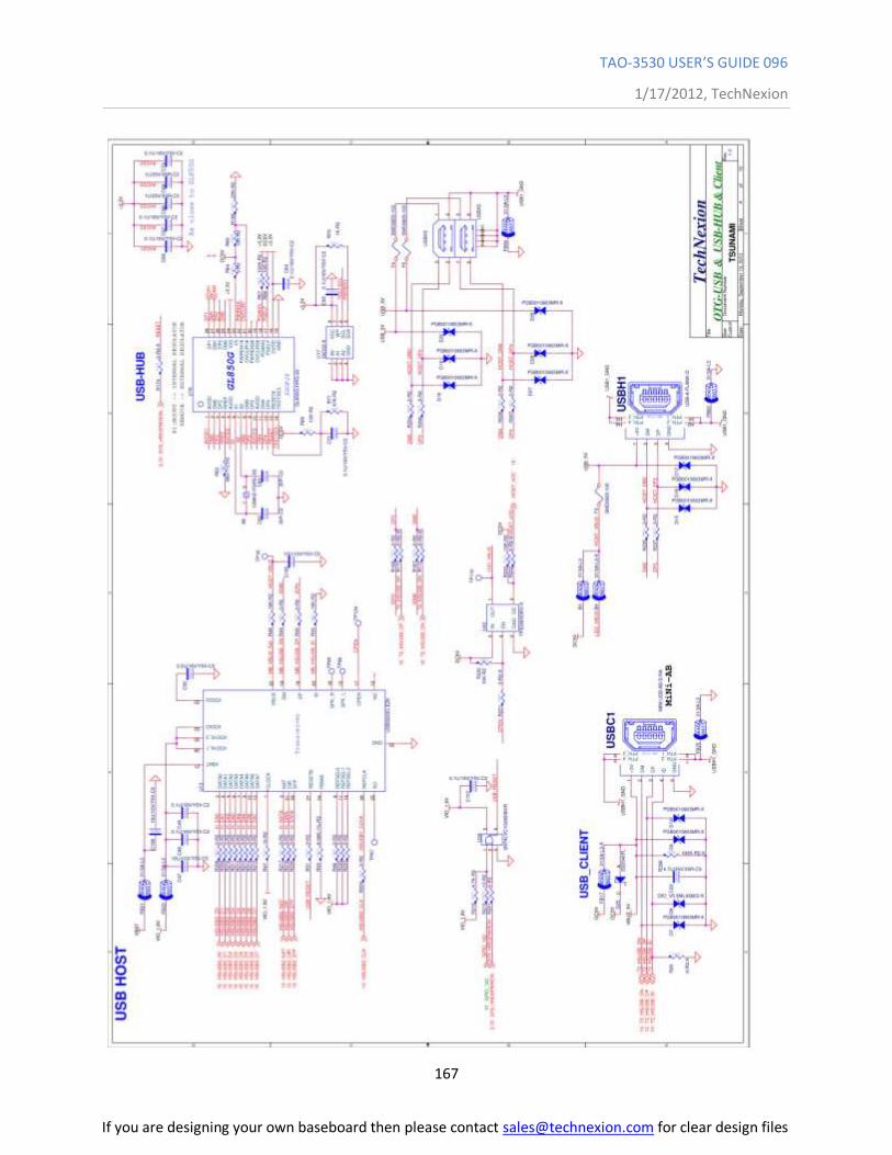
TAO-3530 USER’S GUIDE 096
1/17/2012, TechNexion
167
If you are designing your own baseboard then please contact [email protected] for clear design files
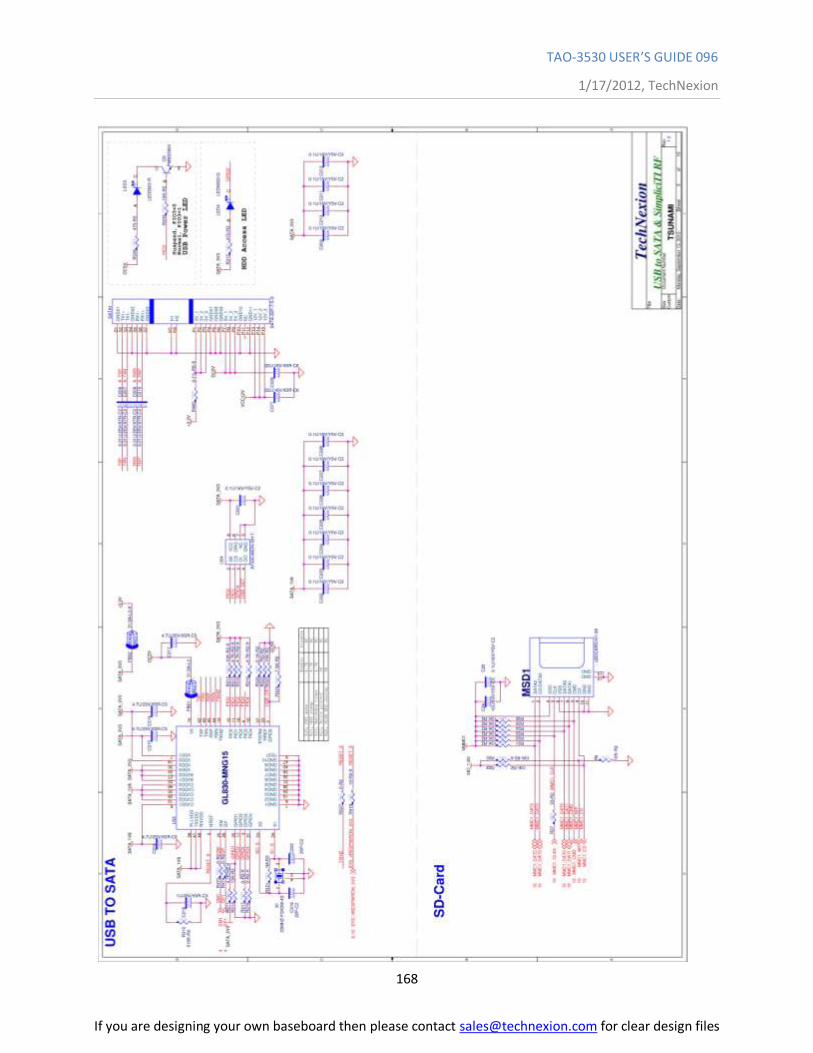
TAO-3530 USER’S GUIDE 096
1/17/2012, TechNexion
168
If you are designing your own baseboard then please contact [email protected] for clear design files
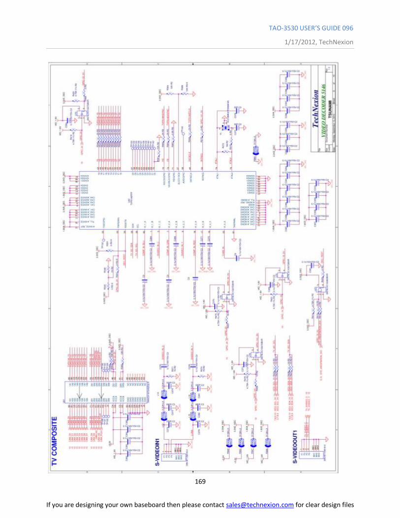
TAO-3530 USER’S GUIDE 096
1/17/2012, TechNexion
169
If you are designing your own baseboard then please contact [email protected] for clear design files
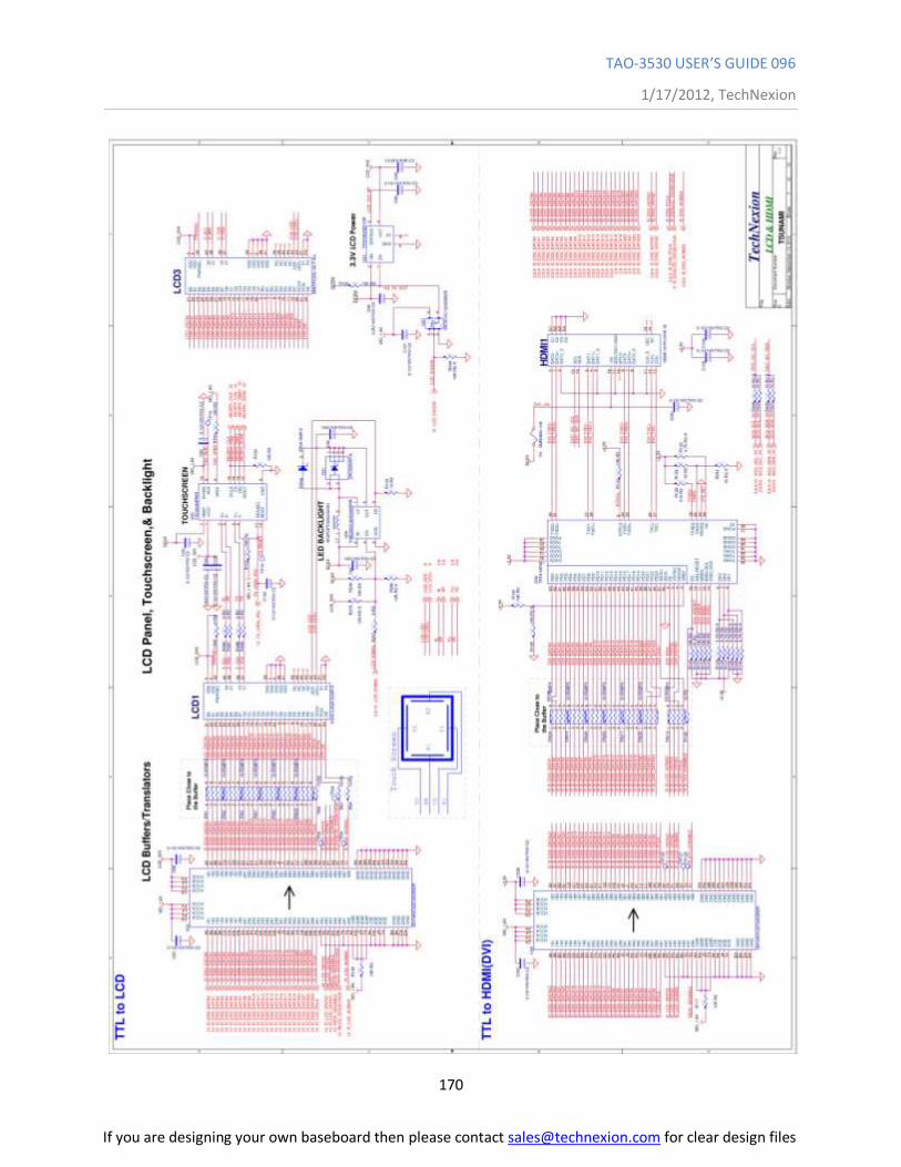
TAO-3530 USER’S GUIDE 096
1/17/2012, TechNexion
170
If you are designing your own baseboard then please contact [email protected] for clear design files
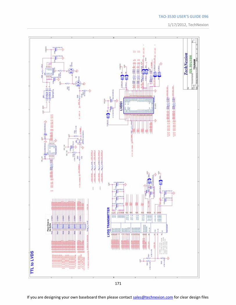
TAO-3530 USER’S GUIDE 096
1/17/2012, TechNexion
171
If you are designing your own baseboard then please contact [email protected] for clear design files

TAO-3530 USER’S GUIDE 096
1/17/2012, TechNexion
172
If you are designing your own baseboard then please contact [email protected] for clear design files
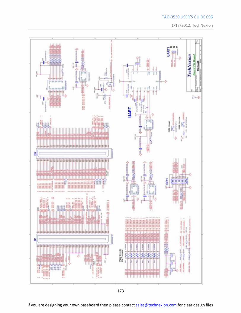
TAO-3530 USER’S GUIDE 096
1/17/2012, TechNexion
173
If you are designing your own baseboard then please contact [email protected] for clear design files
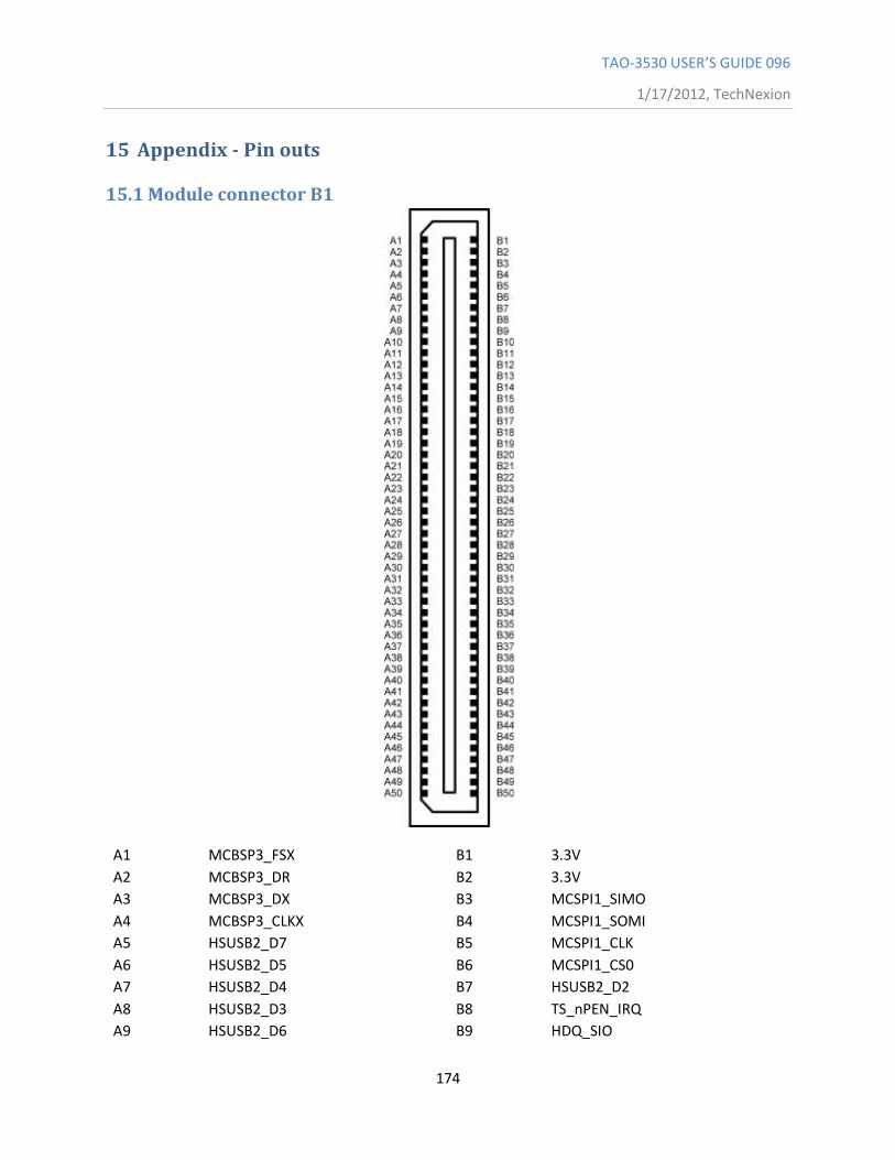
TAO-3530 USER’S GUIDE 096
1/17/2012, TechNexion
174
15 Appendix - Pin outs
15.1 Module connector B1
A1 MCBSP3_FSX B1 3.3V
A2 MCBSP3_DR B2 3.3V
A3 MCBSP3_DX B3 MCSPI1_SIMO
A4 MCBSP3_CLKX B4 MCSPI1_SOMI
A5 HSUSB2_D7 B5 MCSPI1_CLK
A6 HSUSB2_D5 B6 MCSPI1_CS0
A7 HSUSB2_D4 B7 HSUSB2_D2
A8 HSUSB2_D3 B8 TS_nPEN_IRQ
A9 HSUSB2_D6 B9 HDQ_SIO
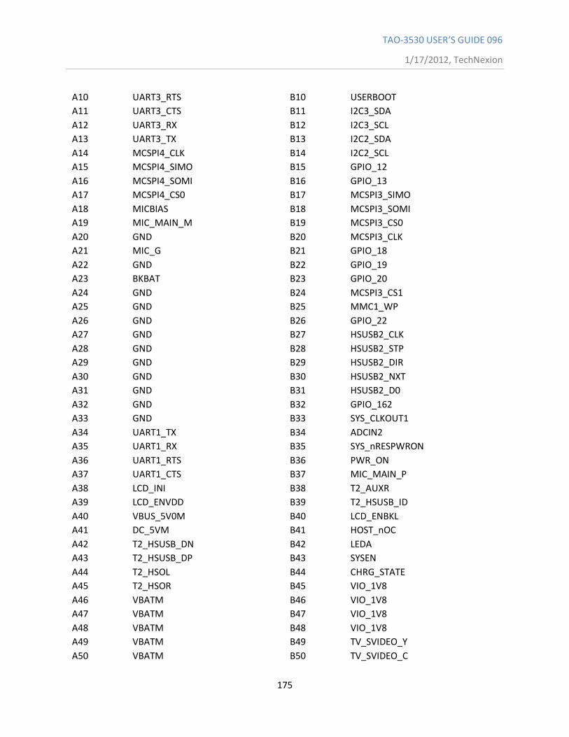
TAO-3530 USER’S GUIDE 096
1/17/2012, TechNexion
175
A10 UART3_RTS B10 USERBOOT
A11 UART3_CTS B11 I2C3_SDA
A12 UART3_RX B12 I2C3_SCL
A13 UART3_TX B13 I2C2_SDA
A14 MCSPI4_CLK B14 I2C2_SCL
A15 MCSPI4_SIMO B15 GPIO_12
A16 MCSPI4_SOMI B16 GPIO_13
A17 MCSPI4_CS0 B17 MCSPI3_SIMO
A18 MICBIAS B18 MCSPI3_SOMI
A19 MIC_MAIN_M B19 MCSPI3_CS0
A20 GND B20 MCSPI3_CLK
A21 MIC_G B21 GPIO_18
A22 GND B22 GPIO_19
A23 BKBAT B23 GPIO_20
A24 GND B24 MCSPI3_CS1
A25 GND B25 MMC1_WP
A26 GND B26 GPIO_22
A27 GND B27 HSUSB2_CLK
A28 GND B28 HSUSB2_STP
A29 GND B29 HSUSB2_DIR
A30 GND B30 HSUSB2_NXT
A31 GND B31 HSUSB2_D0
A32 GND B32 GPIO_162
A33 GND B33 SYS_CLKOUT1
A34 UART1_TX B34 ADCIN2
A35 UART1_RX B35 SYS_nRESPWRON
A36 UART1_RTS B36 PWR_ON
A37 UART1_CTS B37 MIC_MAIN_P
A38 LCD_INI B38 T2_AUXR
A39 LCD_ENVDD B39 T2_HSUSB_ID
A40 VBUS_5V0M B40 LCD_ENBKL
A41 DC_5VM B41 HOST_nOC
A42 T2_HSUSB_DN B42 LEDA
A43 T2_HSUSB_DP B43 SYSEN
A44 T2_HSOL B44 CHRG_STATE
A45 T2_HSOR B45 VIO_1V8
A46 VBATM B46 VIO_1V8
A47 VBATM B47 VIO_1V8
A48 VBATM B48 VIO_1V8
A49 VBATM B49 TV_SVIDEO_Y
A50 VBATM B50 TV_SVIDEO_C
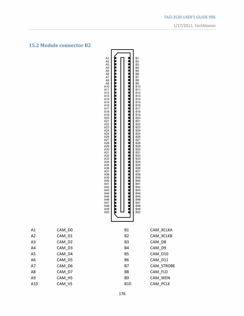
TAO-3530 USER’S GUIDE 096
1/17/2012, TechNexion
176
15.2 Module connector B2
A1 CAM_D0 B1 CAM_XCLKA
A2 CAM_D1 B2 CAM_XCLKB
A3 CAM_D2 B3 CAM_D8
A4 CAM_D3 B4 CAM_D9
A5 CAM_D4 B5 CAM_D10
A6 CAM_D5 B6 CAM_D11
A7 CAM_D6 B7 CAM_STROBE
A8 CAM_D7 B8 CAM_FLD
A9 CAM_HS B9 CAM_WEN
A10 CAM_VS B10 CAM_PCLK
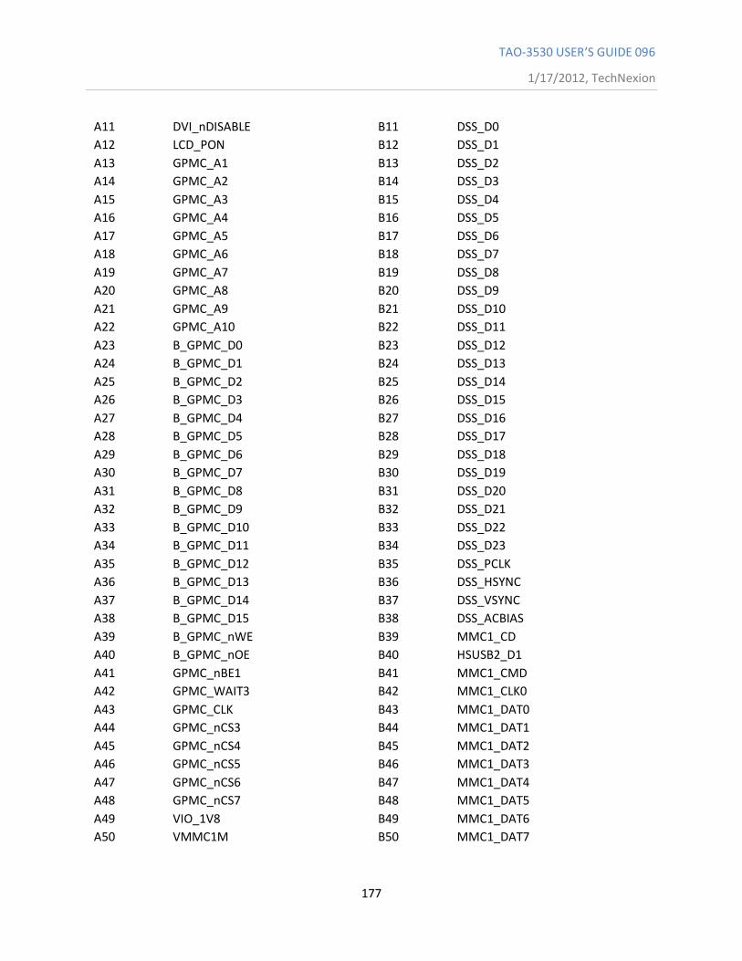
TAO-3530 USER’S GUIDE 096
1/17/2012, TechNexion
177
A11 DVI_nDISABLE B11 DSS_D0
A12 LCD_PON B12 DSS_D1
A13 GPMC_A1 B13 DSS_D2
A14 GPMC_A2 B14 DSS_D3
A15 GPMC_A3 B15 DSS_D4
A16 GPMC_A4 B16 DSS_D5
A17 GPMC_A5 B17 DSS_D6
A18 GPMC_A6 B18 DSS_D7
A19 GPMC_A7 B19 DSS_D8
A20 GPMC_A8 B20 DSS_D9
A21 GPMC_A9 B21 DSS_D10
A22 GPMC_A10 B22 DSS_D11
A23 B_GPMC_D0 B23 DSS_D12
A24 B_GPMC_D1 B24 DSS_D13
A25 B_GPMC_D2 B25 DSS_D14
A26 B_GPMC_D3 B26 DSS_D15
A27 B_GPMC_D4 B27 DSS_D16
A28 B_GPMC_D5 B28 DSS_D17
A29 B_GPMC_D6 B29 DSS_D18
A30 B_GPMC_D7 B30 DSS_D19
A31 B_GPMC_D8 B31 DSS_D20
A32 B_GPMC_D9 B32 DSS_D21
A33 B_GPMC_D10 B33 DSS_D22
A34 B_GPMC_D11 B34 DSS_D23
A35 B_GPMC_D12 B35 DSS_PCLK
A36 B_GPMC_D13 B36 DSS_HSYNC
A37 B_GPMC_D14 B37 DSS_VSYNC
A38 B_GPMC_D15 B38 DSS_ACBIAS
A39 B_GPMC_nWE B39 MMC1_CD
A40 B_GPMC_nOE B40 HSUSB2_D1
A41 GPMC_nBE1 B41 MMC1_CMD
A42 GPMC_WAIT3 B42 MMC1_CLK0
A43 GPMC_CLK B43 MMC1_DAT0
A44 GPMC_nCS3 B44 MMC1_DAT1
A45 GPMC_nCS4 B45 MMC1_DAT2
A46 GPMC_nCS5 B46 MMC1_DAT3
A47 GPMC_nCS6 B47 MMC1_DAT4
A48 GPMC_nCS7 B48 MMC1_DAT5
A49 VIO_1V8 B49 MMC1_DAT6
A50 VMMC1M B50 MMC1_DAT7
TAO-3530 USER’S GUIDE 096
1/17/2012, TechNexion
178
Above schematic block are the 2 connectors from the module towards your interface base
board. Keep note of the following requirements.
1. Provide 5VDC on the signals requesting them.
2. Provide 4.2VDC on the VBAT pins towards the module. (you need provide this from your
baseboard)
3. When using TAO-3530W (with wireless) you also need to provide 3.3VDC. If you don't have
wireless. You can ignore this requirement.
4. Connect all GND pins to GROUND.
5. If you don't have a BKBAT please connect A23 on connector B1 to GND. Don't let it floating.
6. If you don't implement microphone function. Please connect pin A19 and A21 on connector
B1 to GND
All 1.8V signals are generated on the module and are OUTPUTS from the module towards the
interface base boards. They will be used towards the GPIO's for example.
For the Pin out and for changing the signals on the pins, it is recommended to read the TAO-
3530-hardware-manual, which describes how signals can be multiplexed.
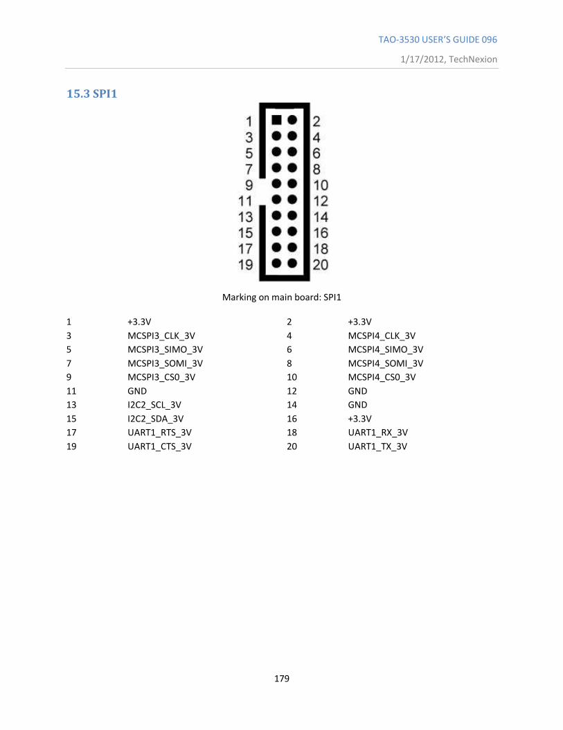
TAO-3530 USER’S GUIDE 096
1/17/2012, TechNexion
179
15.3 SPI1
Marking on main board: SPI1
1 +3.3V 2 +3.3V
3 MCSPI3_CLK_3V 4 MCSPI4_CLK_3V
5 MCSPI3_SIMO_3V 6 MCSPI4_SIMO_3V
7 MCSPI3_SOMI_3V 8 MCSPI4_SOMI_3V
9 MCSPI3_CS0_3V 10 MCSPI4_CS0_3V
11 GND 12 GND
13 I2C2_SCL_3V 14 GND
15 I2C2_SDA_3V 16 +3.3V
17 UART1_RTS_3V 18 UART1_RX_3V
19 UART1_CTS_3V 20 UART1_TX_3V
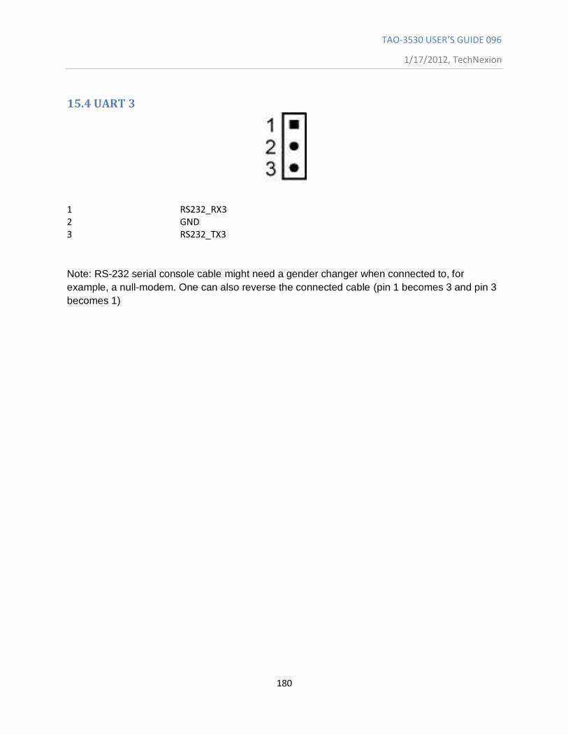
TAO-3530 USER’S GUIDE 096
1/17/2012, TechNexion
180
15.4 UART 3
1 RS232_RX3 2 GND 3 RS232_TX3
Note: RS-232 serial console cable might need a gender changer when connected to, for
example, a null-modem. One can also reverse the connected cable (pin 1 becomes 3 and pin 3
becomes 1)
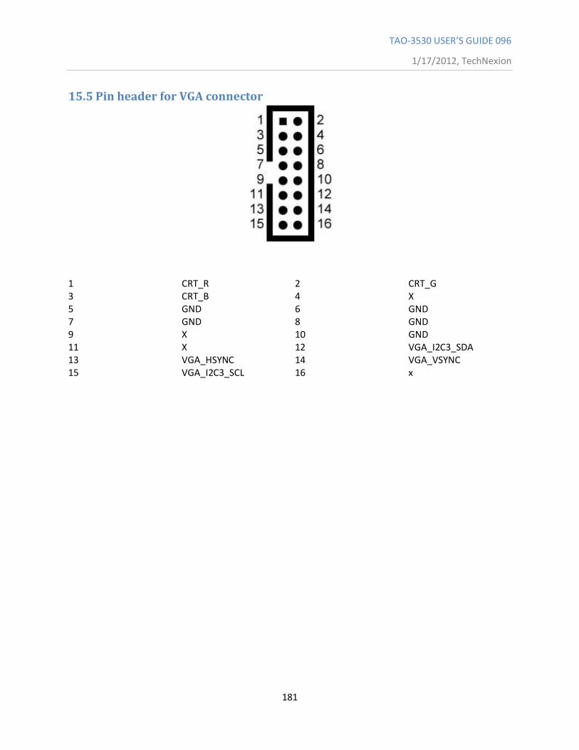
TAO-3530 USER’S GUIDE 096
1/17/2012, TechNexion
181
15.5 Pin header for VGA connector
1 CRT_R 2 CRT_G 3 CRT_B 4 X 5 GND 6 GND 7 GND 8 GND 9 X 10 GND 11 X 12 VGA_I2C3_SDA 13 VGA_HSYNC 14 VGA_VSYNC 15 VGA_I2C3_SCL 16 x
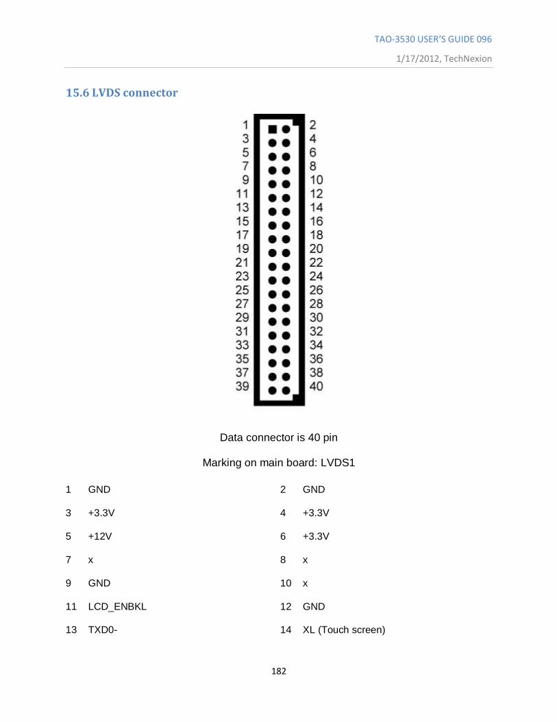
TAO-3530 USER’S GUIDE 096
1/17/2012, TechNexion
182
15.6 LVDS connector
Data connector is 40 pin
Marking on main board: LVDS1
1 GND 2 GND
3 +3.3V 4 +3.3V
5 +12V 6 +3.3V
7 x 8 x
9 GND 10 x
11 LCD_ENBKL 12 GND
13 TXD0- 14 XL (Touch screen)
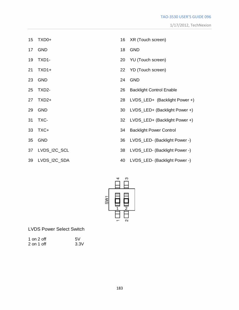
TAO-3530 USER’S GUIDE 096
1/17/2012, TechNexion
183
15 TXD0+ 16 XR (Touch screen)
17 GND 18 GND
19 TXD1- 20 YU (Touch screen)
21 TXD1+ 22 YD (Touch screen)
23 GND 24 GND
25 TXD2- 26 Backlight Control Enable
27 TXD2+ 28 LVDS_LED+ (Backlight Power +)
29 GND 30 LVDS_LED+ (Backlight Power +)
31 TXC- 32 LVDS_LED+ (Backlight Power +)
33 TXC+ 34 Backlight Power Control
35 GND 36 LVDS_LED- (Backlight Power -)
37 LVDS_I2C_SCL 38 LVDS_LED- (Backlight Power -)
39 LVDS_I2C_SDA 40 LVDS_LED- (Backlight Power -)
LVDS Power Select Switch
1 on 2 off 5V 2 on 1 off 3.3V
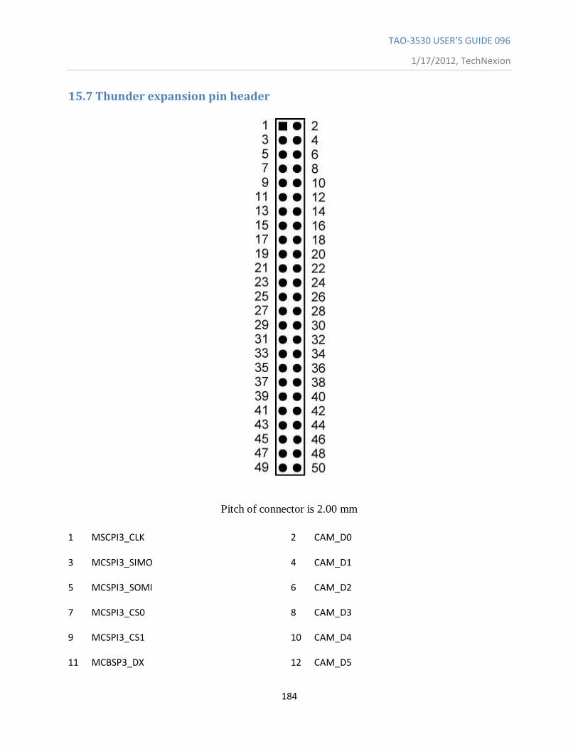
TAO-3530 USER’S GUIDE 096
1/17/2012, TechNexion
184
15.7 Thunder expansion pin header
Pitch of connector is 2.00 mm
1 MSCPI3_CLK 2 CAM_D0
3 MCSPI3_SIMO 4 CAM_D1
5 MCSPI3_SOMI 6 CAM_D2
7 MCSPI3_CS0 8 CAM_D3
9 MCSPI3_CS1 10 CAM_D4
11 MCBSP3_DX 12 CAM_D5
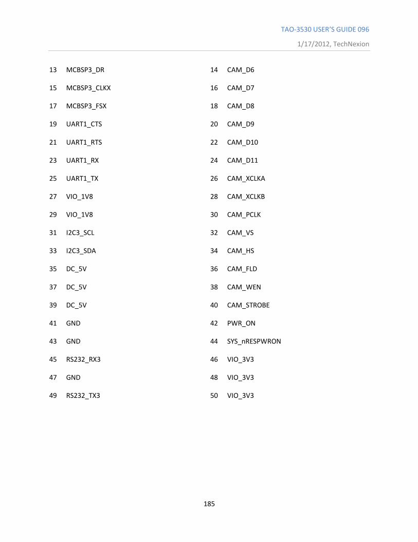
TAO-3530 USER’S GUIDE 096
1/17/2012, TechNexion
185
13 MCBSP3_DR 14 CAM_D6
15 MCBSP3_CLKX 16 CAM_D7
17 MCBSP3_FSX 18 CAM_D8
19 UART1_CTS 20 CAM_D9
21 UART1_RTS 22 CAM_D10
23 UART1_RX 24 CAM_D11
25 UART1_TX 26 CAM_XCLKA
27 VIO_1V8 28 CAM_XCLKB
29 VIO_1V8 30 CAM_PCLK
31 I2C3_SCL 32 CAM_VS
33 I2C3_SDA 34 CAM_HS
35 DC_5V 36 CAM_FLD
37 DC_5V 38 CAM_WEN
39 DC_5V 40 CAM_STROBE
41 GND 42 PWR_ON
43 GND 44 SYS_nRESPWRON
45 RS232_RX3 46 VIO_3V3
47 GND 48 VIO_3V3
49 RS232_TX3 50 VIO_3V3
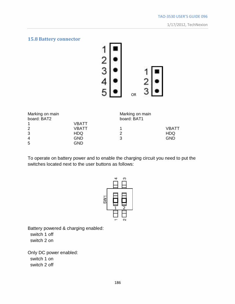
TAO-3530 USER’S GUIDE 096
1/17/2012, TechNexion
186
15.8 Battery connector
OR
Marking on main board: BAT2
Marking on main board: BAT1
1 VBATT 2 VBATT 1 VBATT 3 HDQ 2 HDQ 4 GND 3 GND 5 GND
To operate on battery power and to enable the charging circuit you need to put the
switches located next to the user buttons as follows:
Battery powered & charging enabled:
switch 1 off
switch 2 on
Only DC power enabled:
switch 1 on
switch 2 off
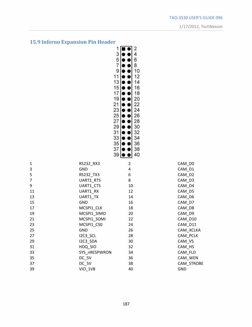
TAO-3530 USER’S GUIDE 096
1/17/2012, TechNexion
187
15.9 Inferno Expansion Pin Header
1 RS232_RX3 2 CAM_D0 3 GND 4 CAM_D1 5 RS232_TX3 6 CAM_D2 7 UART1_RTS 8 CAM_D3 9 UART1_CTS 10 CAM_D4 11 UART1_RX 12 CAM_D5 13 UART1_TX 14 CAM_D6 15 GND 16 CAM_D7 17 MCSPI1_CLK 18 CAM_D8 19 MCSPI1_SIMO 20 CAM_D9 21 MCSPI1_SOMI 22 CAM_D10 23 MCSPI1_CS0 24 CAM_D11 25 GND 26 CAM_XCLKA 27 I2C3_SCL 28 CAM_PCLK 29 I2C3_SDA 30 CAM_VS 31 HDQ_SIO 32 CAM_HS 33 SYS_nRESPWRON 34 CAM_FLD 35 DC_5V 36 CAM_WEN 37 DC_5V 38 CAM_STROBE 39 VIO_1V8 40 GND
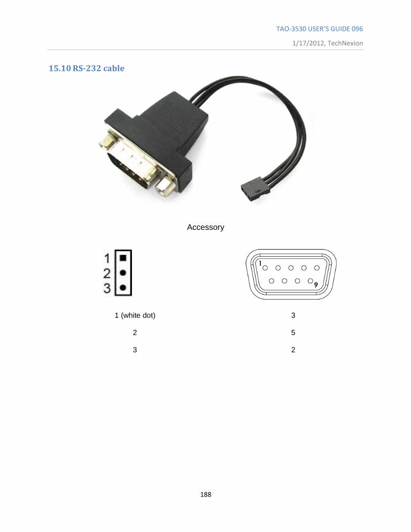
TAO-3530 USER’S GUIDE 096
1/17/2012, TechNexion
188
15.10 RS-232 cable
Accessory
1 (white dot) 3
2
5
3
2