Embed Size (px)
Citation preview

....
------,,..
-
-
'-tJ ENTERED ---- ¢ TRANSWESTERN PIPELINE COMPANY AnENERGY TRANSFERCC1111f!Ony
May 26, 2017
Mr. Dave Cobrain New Mexico Hazardous Waste Bureau New Mexico Environment Department 2905 Rodeo Park Drive East, Building 1 Santa Fe, New Mexico 87505-6313
RE: Submittal of Revised Operation and Maintenance and Monitoring (O&MM) Plan For the Former Surface Impoundments Annual Report Roswell Compressor Station No. 9 Transwestem Pipeline Company, LLC Roswell, Chavez County, New Mexico NMOCD Case #GW-052/EPA ID NO. NMD986676955
Dear Mr. Cobrain:
In response to the "Notice of Revisions to Operation and Maintenance (O&M) and Monitoring Plan" correspondence from the New Mexico Environmental Department (NMED) dated April 18, 2017; and in general accordance with Section IV.A - Remediation System and Groundwater Monitoring of the March 2013 Stipulated Final Orderfor Transwestem Pipeline Company, LLC's (Transwestern) Roswell Compressor Station No. 9 (Site), attached for your review is the Revised Operation and Maintenance and Monitoring (O&MM) Plan for the site. This plan has revised to allow flexibility for recovery system optimization and update the Sampling and Analysis Plan (SAP).
If you have any questions or comments regarding this submission, please do not hesitate to contact me at 210.870.2725 (office) or JD Haines of EarthCon Consultants, Inc. at (317) 450-6126.
Sincerely,
Stacy Boultinghouse, PG(Tx48891lA73) Environmental Manager Transwestern Pipeline Company, LLC [email protected]
Attachment: Operation and Maintenance and Monitoring Plan
ec: Electronic Submissions Kristen Van Horn, Hazardous Waste Bureau, New Mexico Environment Department Brad Billings, Environmental Bureau, New Mexico Oil Conservation Division New Mexico OU Conservation Division (Artesia) New Mexico State Land Office Laurie King, US Environmental Protection Agency - Region 6 Larry Campbell - Transwestem Pipeline Company (Roswell, NM) Rachel Andrews - EarthCon Consultants, Inc. JD Haines - EarthCon Consultants, Inc.
1300 Main Street Houston, Texas 77002 (713) 989-7000

-
---
OPERATION AND MAINTENANCE AND MONITORING (O&MM) PLAN
TRANSWESTERN ROSWELL COMPRESSOR STATION NO. 9 ROSWELL, CHAVEZ COUNTY, NEW MEXICO
NMED 1656; NMOCD Case #GW-052 EPA ID NO. NMD986676955
PREPARED FOR:
TRANSWESTERN PIPELINE COMPANY, LLC 800 EAST SONTERA BLVD., SUITE 400
SAN ANTONIO, TX 78258
PREPARED BY:
EARTHCON CONSULTANTS, INC. 1880 WEST OAK PARKWAY, SUITE 106
MARIETTA, GA 30066 (770) 973-2100
EarthCon Project No. 02.20120037.00
SEPTEMBER 2015 (Revised May 2017)

'"'"
-·
--
-----
-
-
OPERATION & MAINTENANCE PLAN - Compressor Station No. 9 Roswell, New Mexico Page Ii
CONTENTS 1.0 INTRODUCTION ................................................................................................... 1
2.0 SAFETY ................................................................................................................. 1
3.0 OPERATION ......................................................................................................... 1
3.1 Overall System Operation ............................................................................................. 2
3.2 Soil Vapor Extraction and Treatment System ............................................................... 2
3.3 Groundwater Extraction and Treatment System ........................................................... 3
3.4 Automated Logic Control Description ............................................................................ 4
4.0 MONITORING ....................................................................................................... 6
4.1 System Monitoring ........................................................................................................ 6
4.2 Groundwater Monitoring ............................................................................................... 9
5.0 MAINTENANCE .................................................................................................. 11
FIGURES
Figure 1 : Site Location Map Figure 2: Remediation System Layout Plan Figure 3: Equipment Compound Detail Plan Figure 4: Process and Instrumentation Diagram - Groundwater Extraction and Treatment Figure 5: Process and Instrumentation Diagram - Soil Vapor Extraction and Treatment
ATTACHMENT
Attachment A: Monitoring Forms

OPERATION & MAINTENANCE PLAN - Compressor Station No. 9 Roswell, New Mexico Page 11
1.0 INTRODUCTION
"'" This Revised Operating and Maintenance and Monitoring (O&MM) Plan was prepared by EarthCon
- Consultants, Inc. (EarthCon) on behalf of Transwestern Pipeline Company, LLC (Transwestern) for
the former Surface lmpoundment project at the Transwestern Compressor Station No. 9 (also
known as the Roswell Compressor Station) property (the "Site") located at 6381 North Main Street
in Roswell, New Mexico (Figure 1, Site Location Map). On March 13,, 2013, the New Mexico
Environment Department (NMED) issued a Stipulated Order (SO) that governs on-going
environmental response activities associated with the Site. This Revised O&MM Plan was
developed in general accordance with Section IV of the SO and the Site's Stage 2 Abatement Plan
(AP), dated December 3, 2015 and approved by New Mexico Oil and Conservation District (OCD)
on March 1, 2016. This O&MM Plan provides information about the operation, maintenance, and
monitoring of the Site's multiphase extraction (MPE) remediation system.
~Jl-ilH
-
2.0 SAFETY
Prior to operating the system, technical operational and maintenance documents supplied by the
original equipment manufacturer (OEM) for each equipment component (i.e. blower, thermal
oxidizer, pumps, and air compressor) should be reviewed for safe and proper operation. The
emergency shut-off power switch should be clearly marked and identified at the facility to implement
emergency procedures. A Health and Safety Plan (HASP), including an emergency response plan,
should be reviewed and appropriate personal protective equipment (PPE) should be donned and/or
acquired prior to performing system operation or maintenance. Only tra~ned personnel should be
operating and monitoring the MPE system.
3.0 OPERATION
The MPE remediation system consists of soil vapor extraction (SVE) and vapor treatment, and
groundwater/phase-separated hydrocarbons (PSH) recovery and treatment. Operating
components of the MPE remediation system (i.e. pneumatic pumps) may be manipulated
periodically to optimize recovery system efforts, as described further in Section 3.1 of this document.
The layout of the remediation system is presented in Figure 2 and the equipment compound detail
is presented in Figure 3. The process and instrumentation diagram of the SVE system and

OPERATION & MAINTENANCE PLAN - Compressor Station No. 9 Roswell, New Mexico Page 12
''"" groundwater extraction and treatment (GET) system is presented in Figure 4 and Figure 5,
respectively.
-
--
-~~Ji'
---·
3.1 Overall System Operation
The MPE remediation system operation will be optimized in a manner to maximize contaminant
removal while minimizing the length of the remediation process. Given that remediation at the Site
has been ongoing for over 1 O years with measurable thickness of PSH remaining, operations need
to be changed to evaluate the effect of differing system operating parameters on mass removal,
PSH thickness and radius of influence. During the optimization process, data will be collected that
assist in determining what changes may be made to system operations that could increase both the
effectiveness and decrease the timeframe for the remediation. The details, data and results of
system optimization will be reported in the Annual Report for the Site. Additional details on the
system and groundwater monitoring plans are summarized in Sections 4.1 and 4.2 of this document.
3.2 Soil Vapor Extraction and Treatment System
The SVE and treatment system can handle a total air flowrate of approximately 400 standard cubic
feet per minute (scfm) with vapor concentrations ranging between 50°/c, Lower Explosive Limits
(LEL) and 60% LEL in thermal mode. Soil vapor is extracted from SVE-only wells and MPE wells
using two vacuum blowers and routed to two Baker Furnace 200 thermal oxidizer units for treatment
prior to being discharged to the atmosphere. A vacuum is applied to each well by two positive
displacement (PD) rotary lobe blowers located on the thermal oxidizers for extracting soil vapor.
Extracted vapors from the wells are connected by a common manifold piping system and enter two
55-gallons air water separator drums (also known as knock-out tanks) to separate condensate
entrained in the vapor stream. Separated condensate is transferred by pneumatic diaphragm
pumps operated on a time sequence and processed through the groundwater treatment system.
Separated vapors continue through the PD vacuum blowers and into the thermal oxidizers for
treatment. Treated vapors are discharged to the atmosphere.
The Baker Furnace 200 thermal oxidizer is a skid mounted system used for treating vapor-phase
volatile organic compounds (VOCs) (destruction efficiency of 99%) of SVE systems. Each thermal
oxidizer is capable of processing an air flow rate of 200 scfm and treating VOC concentrations with
a LEL ranging between 50% and 60% in thermal mode. The thermal oxidizer is equipped with a
10-horse power (hp) PD blower capable of 200 cfm at 4 inches of mercury ("Hg), a 12 gallon KO

-
-
----
OPERATION & MAINTENANCE PLAN - Compressor Station No. 9 Roswell, New Mexico Page 13
pot with drain ports, air filters, a chart recorder, interlocking controllers and air flow and pressure
gauges. Natural gas combined with the influent VOC vapor stream extracted from wells is used to
supply fuel to the thermal oxidizer for achieving operating temperature of greater than 1,450 degree
Fahrenheit (°F) in the combustion chamber. The thermal oxidizer is capable of operating in catalytic
mode to reduce supplemental fuel usage if equipped with catalytic blocks and concentrations are
less than 20% LEL.
3.3 Groundwater Extraction and Treatment System
The GET system can handle a water flow rate of 20 gallons per minute (gpm). Groundwater and
PSH are recovered by operating pneumatic pumps installed in MPE we~lls. The MPE wells are
connected into four groups, which are labeled as Circuit A, Circuit B, Circuit C, and Circuit D. At
each circuit, the recovered fluids are conveyed from pneumatic pumps through a common manifold
and deposited in a 200-gallon holding tank. A 15-hp rotary screw air compressor rated for 67 cfm
at 100 pounds per square inch (psi) is used to supply compressed air to the pneumatic pumps and
the knock-out tank diaphragm pump for the SVE system. Once fluids reach a certain level in the
"""' holding tanks, % hp centrifugal transfer pumps deliver the recovered fluids to a 90-barrel
- (approximately 2,800 gallons) aboveground storage tank that serves as surge tank and separation
unit of PSH and groundwater. Separated PSH in the surge tank is removed manually and sent off-
-
---
-
site to a permitted facility for recycling. Separated groundwater is transfc3rred by gravity from the
surge tank to a 325 gallon equalization tank and a 100 gallon holding tank that are connected in
series. From the holding tank, a 1-hp centrifugal pump is used to process separated groundwater
to the air stripper. The air stripper is equipped with a 3-hp regenerative blower to move air within
the 7-tray stripper tower for volatilizing hydrocarbons in groundwater. Emissions from the air
stripper are treated by two 400 pound vapor-phase granular activated carbon (GAC) vessels prior
to discharge to the atmosphere. Once treated, groundwater is pumped by a 1-hp transfer pump
through a 1 O micron bag filter and two 400 pound liquid-phase GAC vessels and stored in a 1,000
gallon aboveground irrigation water tank. After reaching a certain level in the tank, the treated water
is transferred by a 1-hp centrifugal pump through a 10 micron bag filter and disperses the water
through an irrigation system consisting of above ground spray nozzles.
The groundwater extraction piping manifolds, 200-gallon holding tanks, transfer pumps, and the air
compressor are housed in an enclosed building. The surge tank, air stripper, bag filters, carbon

OPERATION & MAINTENANCE PLAN - Compressor Station No. 9 Roswell, New Mexico Page 14
...,, vessels, and irrigation tank are located outside without an enclosure. During cold weather
-
-·
-· -·
-
conditions, the system is deactivated to prevent damage caused by freezing water.
3.4 Automated Logic Control Description
The SVE and treatment system operates independent of the GET system. Each system consists
of logic controllers for automatic operation and deactivation. The following paragraphs provide a
description of the logic control schematic of each system.
Thermal Oxidizer and Vacuum Blowers:
The thermal oxidizer and vacuum extraction blower are integrated as orn:l operating unit. At initial
startup, a 60 second purge (five air changes) cycle of the combustion chamber is performed with
ambient air using the combustion blower prior to ignition of the pilot. According to the OEM manual,
the oxidizer has a 15 second ignition trial which lights the pilot. If the pilot does not light in 15
seconds, the supplemental fuel line is closed to reduce the potential for an explosion. The main
gas valve in the supplemental fuel train will not open until the pilot is lit. The thermal oxidizer must
be reset and the initial startup procedure repeat until activation. The process line of the thermal
oxidizer consists of actuated three-way valves that are used to supply clean air and to restrict
voe vapors provided by the vacuum extraction blower. The voe vapor line is closed from
entering the thermal oxidizer by the three-way valve until the set operating temperature (1,450°
F) is reached. In addition, two actuated valves are linked to oxygen and LEL sensors to prevent
levels from exceeding set points and to add dilution air to the process stream to maintain below
the set points. If the LEL is exceeded, the valve is closed and temporarily shuts down the
combustion burner until the LEL is below the set point. If the combustion or vacuum extraction
blower fails to operate, the control system will close the supplemental fuel line and close the voe vapor line to the oxidizer. The thermal oxidizer is equipped with a high temperature limit controller.
If a high temperature condition exists, the thermal oxidizer will close the supplemental fuel line
and the voe vapor line. The vacuum blower is equipped with a KO pot. The KO pot consists of
level switches to monitor liquids in the KO pot. If liquid levels reach a cHrtain level in the KO pot,
the thermal oxidizer and vacuum blower will be deactivated. The following table includes a list of
relay control sequences for automatic operation and deactivation of the SVE system:

~'
--
-
OPERATION & MAINTENANCE PLAN - Compressor Station No. 9 Roswell, New Mexico Page 15
Table 3.3-1: Relay Control Systems for the SVE System
Component Devices Condition Response
12-gal KO POT Liquid level High-high water Deactivate SVE blower and Thermal switches level Oxidizer
Thermal Temperature High temperature Deactivate SVE blower and Thermal Oxidizer Transducer Oxidizer
Closes Supply Gas valve
Open Dilution Valve
Thermal LEL High LEL Deactivate SVE blower and Thermal Oxidizer Transducer concentration Oxidizer
Closes Supply Gas valve
Open Dilution Valve
Combustion Actuated Startup and Reset Activate Combustion Blower Blower Valve
Groundwater Extraction and Treatment System:
The GET system is integrated using electrical relays, actuated valves, pressure sensors, and
levels switches. The following table includes a list of relay control sequences for automatic
operation and deactivation of the GET system:
Table 3.3-2: Relay Control Systems for the Groundwater Extraction System
Component Devices Condition Response 200-gallon Liquid level High-high water Close air supply line by pressure Holding Tanks switches level switch valvei for Circuit
High water level Activate transfer pump for Circuit
Low water level Deactivate transfer pump for Circuit
90-Barrel Surge Liquid level High-high water Closes air supply line actuated valves Tank switches level for all Circuits 100-gallon Liquid level High water level Activate transfer pump for tank Transfer Tank switches Low water level Deactivate transfer pump for tank
Air Stripper Liquid level High-high water Close pneumatic actuated valve of switches level surge tank Bffluent line Blower pressure High water level Activate transfer pump for air stripper switch Low water level Deactivate transfer pump for air
stripper
Low air pressure Close pneumatic actuated valve of surge tank Hffluent line
Irrigation Tank Liquid level High water level Activate transfer pump for irrigation switches tank

-·
OPERATION & MAINTENANCE PLAN - Compressor Station No. 9 Roswell, New Mexico Page 16
Table 3.3-2: Relay Control Systems for the Groundwater Extraction System Component Devices Condition Response
Low water level Deactivate transfer pump for irrigation tank
Air Compressor Temperature High Deactivate air compressor switch temperature
- STARTUP SEQUENCE
'""
---
-
-
-
1. Confirm all switches are in "off" position 2. Close valves for SVE wells 3. Energize main breaker switch 4. Activate Thermal Oxidizer/SVE Blower- East 5. Activate Thermal Oxidizer/SVE Blower-West 6. Open valves for SVE wells 7. Activate Air Stripper 8. Activate Transfer Pumps 9. Activate Air Compressor 10. Perform operation monitoring
SHUTDOWN SEQUENCE
1. Perform operation monitoring. 2. Deactivate Air Compressor 3. Deactivate Transfer Pumps 4. Deactivate Air Compressor 5. Deactivate Thermal Oxidizer/SVE Blower - East 6. Deactivate Thermal Oxidizer/SVE Blower-West 7. Close valves for SVE wells. 8. De-energize main breaker switch
MALFUNCTION SEQUENCE
1. Identify alarm condition 2. Resolve alarm condition 3. Reset button to clear alarm condition 4. Reactivate system following Start-up Sequence 5. Document alarm condition and resolution.
4.0 MONITORING
4.1 System Monitoring
Routine monitoring of the system will be performed to maintain the operation of the system. In
conjunction with system operations, the monitoring schedule may be adjusted based on system
performance over time. The equipment, meters, gauges, and/or instruments used to collect the
-
-
-· -
....
OPERATION & MAINTENANCE PLAN - Compressor Station No. 9 Roswell, New Mexico Page 17
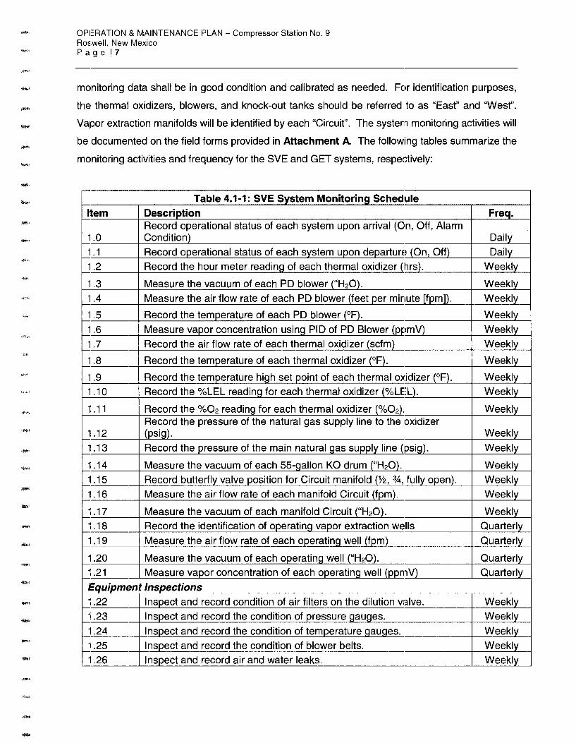
monitoring data shall be in good condition and calibrated as needed. For identification purposes,
the thermal oxidizers, blowers, and knock-out tanks should be referred to as "East" and 'Wesf'.
Vapor extraction manifolds will be identified by each "Circuit". The system monitoring activities will
be documented on the field forms provided in Attachment A. The following tables summarize the
monitoring activities and frequency for the SVE and GET systems, respectively:
Table 4.1-1: SVE System Monitoring Schedule
Item Description Freq. Record operational status of each system upon arrival (On, Off, Alarm
1.0 Condition) Daily
1.1 Record operational status of each system upon departure (On, Off) Daily
1.2 Record the hour meter readinq of each thermal oxidizer (hrs). Weekly
1.3 Measure the vacuum of each PD blower ("H20). Weekly
1.4 Measure the air flow rate of each PD blower (feet per minute [fpm]). Weekly
1.5 Record the temperature of each PD blower (°F). Weekly
1.6 Measure vapor concentration using PIO of PD Blower (ppmV) Weekly
1.7 Record the air flow rate of each thermal oxidizer (scfm) Weekly
1.8 Record the temperature of each thermal oxidizer (°F). Weekly
1.9 Record the temperature high set point of each thermal oxidizer (°F). Weekly
1.10 Record the %LEL readinq for each thermal oxidizer (%LEL). Weekly
1.11 Record the %02 reading for each thermal oxidizer (%02). Weekly Record the pressure of the natural gas supply line to the oxidizer
1.12 (psig). Weekly
1.13 Record the pressure of the main natural gas supply line (psig). Weekly
1.14 Measure the vacuum of each 55-gallon KO drum ("H20). Weekly
1.15 Record butterfly valve position for Circuit manifold (Y2, %, fully open). Weekly
1.16 Measure the air flow rate of each manifold Circuit (fpm). Weekly
1.17 Measure the vacuum of each manifold Circuit ("H20). Weekly
1.18 Record the identification of operating vapor extraction wells Quarterly
1.19 Measure the air flow rate of each operating well (fpm) Quarterly
1.20 Measure the vacuum of each operating well ("H20). Quarterly
1.21 Measure vapor concentration of each operating well (ppmV) Quarterly
Equipment Inspections 1.22 Inspect and record condition of air filters on the dilution valve. Weekly
1.23 Inspect and record the condition of pressure gauges. Weekly
1.24 Inspect and record the condition of temperature qauqes. Weekly
1.25 Inspect and record the condition of blower belts. Weekly
1.26 Inspect and record air and water leaks. Weekly

--,.,.,
-
.....
---
-·
OPERATION & MAINTENANCE PLAN - Compressor Station No. 9 Roswell, New Mexico Page IB
Table 4.1-1: SVE System Monitoring Schedule Item Description
1.27 Inspect and record condition of check valves.
1.28 Drain condensate from KO pots.
1.29 Perform routine maintenance as required by the OEM.
Sampling Collect influent air sample for voe after PD blowers and submit to
1.30 laboratory for analysis of Total VOC by EPA Method T0-15. Leak Detection and Repair Monitoring (after 2 consecutive months of
1.31 non-detect, monitoring can be done quarterly)
Table 4.1-2: Groundwater Extraction System Monitoring Schedule
Item Description Provide the operational status of system upon arrival (On, Off, Alarm
2.0 Condition) Provide the operational status of system upon departure (On, Off, Alarm
2.1 Condition)
2.2 Record air stripper blower static pressure ("H20).
2.3 Record air stripper blower air flow (cfm).
2.4 Record the air stripper rotameter (gpm).
2.5 Record vapor-phase carbon vessel pressure 1 ("H20).
2.6 Record vapor-phase carbon vessel pressure 2 ("H20).
2.7 Record vapor-phase carbon vessel temperature (°F).
2.8 Record Water Meter Readinq (qallons).
2.9 Record air compressor sump tank presssure (psi)
2.10 Record air compressor discharqe presssure (psi)
2.11 Record air compressor hour meter (hr)
2.12 Measure PSH and water level in Surge Tank (feet)
2.13 Measure vapor concentration prior to carbon vessel 1 (ppmV)
2.14 Measure vapor concentration between carbon vessel 1 and 2 (ppmV)
2.15 Measure vapor concentration after carbon vessel 2 (ppmV)
2.16 Measure (bucket test) the water flow rate of each operatinq well (qpm) Measure liquid level readings of each operating well (ft below top of
2.17 casinq)
Equipment Inspections
2.18 Inspect and record the condition of air stripper rotameter. Inspect and record condition of 200 gallon holding tanks (Circuit A, B, C,
2.19 and D). Inspect and record condition of 325 gallon equalization tank and 100 gallon
2.20 holdino tank.
Freq.
Weekly
Weekly
Per OEM
Quarterly
Quarterly
Freq.
Daily
Daily
Weekly
Weekly
Weekly
Weekly
Weekly
Weekly
Weekly
Weekly
Weekly
Weekly
Weekly
Bi-Monthly
Bi-Monthly
Bi-Monthly
Quarterly Semi-Annual
Daily
Daily
Daily

--
--
----
--
-·
OPERATION & MAINTENANCE PLAN - Compressor Station No. 9 Roswell, New Mexico Page 19
Table 4.1-2: Groundwater Extraction System Monitoring Schedule Item Description
2.21 Inspect and record the condition of air flow, and pressure qauqes.
2.22 Inspect and record the condition of bao filters.
2.23 Inspect and record the condition of water meter.
2.24 Inspect air compressor for air leaks.
2.25 Inspect and record air compressor oil level in site tube.
2.26 Inspect air compressor oil return line.
2.27 Drain air receiver and condensate from air compressor filter separator.
2.28 Inspect for water leaks.
2.29 Inspect bao filters and replace as needed.
2.30 Inspect sprinkler heads on the irrioation system.
2.31 Inspect pneumatic pumps.
Sampling 2.32 Collect influent water sample prior to air stripper
2.33 Collect effluent water sample after air stripper
2.34 Collect effluent water sample after liquid-phase carbon vessels
4.2 Groundwater Monitoring
Freq. Daily
Daily
Daily
Daily
Daily
Daily
Daily
Daily
Daily
Daily
As needed
Monthly
Monthly
Monthly
Groundwater sampling will be conducted semi-annually in accordance with the SO and the Stage
2 AP to monitor system effectiveness and the extent of the plume. The! groundwater monitoring
network at the Site consists of 30 monitoring wells. Eighteen of these wells are included in the
sampling and analysis plan (SAP), which lists the sampling frequency and laboratory analytical
results for each monitoring well. The SAP is summarized in the following table:
Table 4.2-1: Groundwater Sampling and Analysis Plan
Well ID 1st Semiannual Event Analytical 2nd Semiannual Event Analytical
Parameters Parameters
MW-13 -- BTEX
MW-14 -- BTEX
MW-16 -- BTEX
MW-20 -- voes
MW-21 BTEX BTEX
MW-22 voes voes
MW-24D -- BTEX
MW-26 -- voes

----
-
OPERATION & MAINTENANCE PLAN - Compressor Station No. 9 Roswell, New Mexico Page 110
Table 4.2-1: Groundwater Sampling and Analysis Plan
Well ID 1st Semiannual Event Analytical 2nd Semiannual Event Analytical
Parameters Parameters MW-27 BTEX BTEX
MW-29 -- BTEX
MW-32 -- BTEX
MW-34 -- BTEX
MW-35 -- BTEX
MW-37 -- BTEX
MW-39 -- voes
MW-40 -- voes
MW-41 voes voes
MW-42 voes voes Notes: 1. BTEX - benzene, toluene, ethylbenzene, xylenes 2. voes - volatile organic compounds 3. BTEX and voes will be analyzed by EPA method 8260
The remediation system shall be deactivated for 48 to 72 hours prior to the start of each sampling
event. Depth to PSH, if present, and depth to groundwater will be measured in each groundwater
monitoring well and MPE well using an optical sensor probe capable of distinguishing between PSH
and groundwater prior to purging and sampling activities. Fluid measurements should be completed
within 48-hours.
Prior to sampling, the monitoring wells will be purged and monitored for stabilization of water quality
parameters, including pH, specific conductance, dissolved oxygen (DO), oxidation-reduction
potential (OAP), and temperature using a calibrated YSI 556 Meter, or equivalent. Purging will be
considered complete when the measured parameters of the purge water stabilize to within 1 O
percent for three consecutive measurements. In addition to the samples collected from the
monitoring wells, the following data quality control samples will be collected and analyzed for either
BTEX or VOes, as required: field duplicates, field blanks, equipment rinsate blanks. The
groundwater monitoring data will be summarized in an annual monitoring report, which will be
submitted to NMED by March 31 of the following year.

-
OPERATION & MAINTENANCE PLAN - Compressor Station No. 9 Roswell, New Mexico Page I 11
5.0 MAINTENANCE
Routine maintenance will be conducted while operating the system to minimize excessive wear and
major failures of equipment components. Maintenance requirements for specific equipment
components is provided in the technical operation and maintenance manuals provided by the OEM.
Only trained personnel should be maintaining the system. General maintenance activities for the
SVE system and GET system equipment components are provided in the1 following table:
Table 5-1: General Maintenance Item Description Freq. 3.1 Grease bearings on vacuum blower Monthly
3.2 Replace Oil Every 6 mos.
3.3 Clean and/or replace KO pot air filter Every 6 mos.
3.4 Clean and/or replace vacuum blower air filter Every 6 mos.
3.5 Replace vacuum blower belts Every 6 mos.
3.6 Replace baq filters Weekly
3.7 Check air compressor belt tension Weekly
3.8 Check air compressor inlet filter element Weekly
3.9 Change air compressor filter Every 6 mos.
3.10 Change air compressor lubricant filter Every 6 mos.
3.11 Check and tighten fittings Weekly
3.12 Clean check valves Every 6 mos.
3.13 Clean air stripper trays Every 6 mos.
3.14 Clean air stripper rotameter Monthly

FIGURES

- - - - - - -
REPORT OF 2016 GROUNDWATER REMEDIATION ACTIVITIES TRANSWESTERN PIPELINE COMPANY, LLC
TRANSWESTERN COMPRESSOR STATION No. 9 (ROSWELL COMPRESSOR STATION )
ROSWELL, CHAVES COUNTY, NEW MEXICO
- - - - -
EARJHCONe
- - - - -
FACILITY BOUNDARY
PROJECT AREA BOUNDARY
-SCALE FEET
-
SOURCE: GOOGLE EARTH PRO AERIAL PHOTOGRAPH, DATED DECEMBER 2015
SITE LOCATION MAP
~ EarthCon Consultants, Inc.
~ L-~~~~~~~P_R_O_J_EC~T_N_o_._0_2_.2_0_12_0_0_3_7~~~~~~--'L-100.......;o _w_ES~T~O-AK_P_K_WY~·~B-LD_G_1_00~.s_T_E_100_.~M_A_Rl_ETT.......;A ,_G~A,_3006~2__.~0AA-WN~• ~~SN~W.......;~~~-E-CKED~· ~~JD~H"'-~~M-~-·.....;2~'1~3'~20~1~7~ ...... FlGU~~-·-1~ ...... Copyright e 2017 Ear1!1Con Consul1ants, Inc. All Rights Reseived

- - - - - - - - - -TRANSWESTERN COMPRESSOR STATION
MW-36
MW-37 • MW-38
•MW-342®
I •MW-35
MW-30 •
6 3 ~ ~ MW-29
•MW-32 • ~ ~
~ 4 5 1
MW-33 •
L J __ r ___.___
Facility Boundary
-- - - -- Project Area Boundary
.,_ -o-- Remediation System Fence
MW-31
• MW-17
Circuit A (5 Wells)
Circuit B (10 Wells)
Circuit C (8 Wells)
Circuit D (8 Wells)
-
MW-18
- - - - -
MW-26 •
MW-23D
MW-9
/ {."'
~
- - -.. :1
MW-39
• • MW-40
/
• MW-42
/
/
2 "-APROXIMATE CENTERLINE
OF 10' PIPELINE EASMENT
/ /
SOURCE: CYPRESS ENGINEERING SERVICES INC.
SCALE IN FEET
0 100 200
EA~HCON® REMEDIATION SYSTEM LAYOUT

- - -
TRANSFER PUMP
- - -
SOUNOID VAL~
-
TRANSFER TANK C
TRANSFER PUMP
TRANSFER PUMP
TRANSFER PUMP
-
COMPRESSED AIR SUPPLY
-
HEADERS
DIAPHRAGM
-
AIR COMPRESSOR
SVE
PUMP WITH'\ TIMER \
MOISTURE SEPARATOR ,.....,__,_~
-
ROU UP DOOR
UP R
- -
1100 GM.. HOPE IRRIGATION TANK
"WEST" THERMAL OXIDIZER W/ SVE BLOWER
"EAST" THERMAL OXIDIZER W/ SVE BLOWER
SHED SHED ---- FROM PLANT---
TOTAL FLUIDS HEADER
---·~-~~~~_J (NOT TO SCALE)
TRANSWESTERN PIPELINE COMPANYCLLC
ROSWELL COMPRESSOR STATION
ROSWELL, CHAVES COUNTY, NEW MEXICO
EARJHCON® ~ EarthCon Consultants, Inc.
- - - -z -
- -~CAL WATIER LEG
EDUIPMENT COMPOUND DETAIL
i\j PROJECTN0. 02.20120037 .00 1880WESTOAKPKWY, BLDG100, STE106, MARIETTA, GA, 30062 DRAWN SSW CHECKED SD DATE 9/25/2015 FKlURE 3 ~ '-~~~~~~~~~~~~~~~~~~~~~~~~~-1...~~~~~~-'-~~-'-~~-'-~~-'--'-~~ ..... ~~_,;;..;;.;.;~~-"-~~~....;;;.~~-""~~------~--' ..... ~~~ ....
Copyright © 2015 E..thCon Consultants, Inc. All Rights Reserved

I I I I I I I I I I I I I I I I I I I
VAPOR
.- - ·- --··-· - · ----··r · ·-··
Component Devices Condition
12·gal KO POT Liquid level switches High-high water level
Thermal Ox id izer Temperature Transd uce r High temperature
~
CIRCUIT C 10 POINTS
VAPOR
CIRCUIT D 9 POINTS
VAPOR
TYP.
CIRCUIT SHALLOW 10 POINTS
VAPOR
COMBUSTION BLOWER (FAN)
...... - . . . . . ............ .
1 + )
AIR -+-TIMER -+-- AIR COMPRESSOR 1"-1>----'1'-t GAST KO DRUM
TO SURGE TANK OF GWTS
~GASTKO DRUM
SANDPIPER 6 GPM 0 40 PSI
SET TEMP POINT(!) CD
I I
r:=:l 0 CHART ~ RECORDER ~~ ATlt.40SPHERE DILUTION
l ~
t ·Cf! ~'"''"",: r1- . J_ ~l~I"'"' ~ ·
BID dJ..._ ~ H :;;, . "' PITOT V _I:_~ """ LI ,_, --~ L----=-=::-:-:- FOR ROOTS PD BLOWER ~ '"" TI<ERM>C OHMH '50HP U"I 12-G'L
OXIDIZER 230/460V/34> 200 CFM
200 CFM O 4"H20
/,~
/,
COMBUSTION BLOWER (FAN)
I~+- ATlt.40SPHERE
SET TEMP
POINTCV CV ...... . . · 1 PANEL ~0· ~~ART
RECORDER . at V SUPPLIED AIR
~oro ~ J I T '"""'" '.1'W..- : ' T '"-" ~ ~ 4" ,,:i:, BAKER '""""- I ' BID ,f-J ~~ II • ,4, ' II --- OXIDIZER CHART
lcSHH ·
LSl (, 200 CFM ROOTS PD BLOWER
150HP URAi 230/460V/34>
200 CFM 0 4"H20
~~ 12-GAL
Response
Deactivate SVE blower and Th ermal Oxidize r
Deactivate SVE blower and Th ermal Oxidizer
LEGEND
VAPOR EXTRACTOR PROCESS LINES
,------,--- TOTAL FLUID EXTRACTION LINES
NATURE GAS
) I ~ ........ ELECTRICAL LINE
CP CONTROL PANEL
F AIR FLOW
GWTS GROUNDWATER TREATlt.4ENT SYSTEM
KO KNOCKOUT
LSHH LEVEL SWITCH HIGH-HIGH
LSH LEVEL SWITCH HIGH
LSL LEVEL SWITCH LOW
p PRESSURE
T TEMPERATURE
YES VAPOR EXTRACTION SYSTEM
l~I ACTUATED VALVE
cxx:J BALL VALVE
N BUffiRFLY VALVE
lr1 CHECK VALVE
[><] GATE VALVE
II PIPE UNION
ifil. ALARM
0 GAUGES
I c:::J ROTAMETER
~ PRESSURE SWITCH VALVE
121 PRESSURE REGULATOR
t PRESSURE RELIEF VALVE
t VACUUM RELIEF VALVE
+- SAMPLE PORT
~ TRANSDUCER
EJ CONTROL PANEL
ll1I DIAPHRAGM PUMP
ffiE FLAME ARRESTOR
C=> MUFFLER u BLOWER
@F TRANSFER PUMP
Closes Supply Gas valve
Open Dilution Valve TRANSWESTERN PIPELINE COMPANYClLC
ROSWELL COMPRESSOR STATION EARJHCON® PROCESS AND INSTRUMENTATION DIAGRAM
FOR SOIL VAPOR EXTRACTION AND Deactivate SVE blower and Thermal Oxidizer
TREATMENT SYSTEM ~ open Dilution v alve EarthCon Consultants, Inc. _ . ~ CJAAWN· CliECKED: DA1E FIGURE. 4 ~ l~~c:o:m:b:us~ti:o:n :Bl:o:::we r~A=ct=ua~t=ed~V~a~lv~e::::::~S~ta~rt~u~p~a~nd~R~e~se~t::::::'.:A~ct~i~va~t~e :Co~m:b~u~st:io:n:B:l o:w:e:r:::::::::::._~~~~~~~~.l~~~~~~~~~P~R~O~J~E~C~T:_:::N:0:·~0~2~.:2~0~12~0~0~3~7~.~0~0~~~~~~...J_..,:1~88~0~W~E~S~T~O:A:K~P:KWY::.:,;,~B~LD~G::.:;100::::::.;, S~T~E~1~06~, ~MA::::.;:Rl~E~n~A~, G~A~,~30~0~6~2...J~~· ~~S~S~W~~-..J"-~~~~S~D:._~...1..~~_:;:.9/~2~5/~1~5~~.1...~~~....J ~
Thermal Ox id izer LEL Transduce r High LEL concentrat ion Closes Supply Gas valve ROSWELL CHAVES COUNTY, NEW MEXICO
Copyright C 2015 EarthCon Consultants, Inc. All Rights Reserved

I I I I I I I I I I I I I I I I I I I
CIRCUIT C 11 POINTS
CIRCUIT D 8 POINTS
CIRCUIT A 5 POINTS
200-GAL: HOLDING
TANK
································ · ············ ·· ····· ·· ···· · ·· · · ··· f::l·
L'tJ
I_ AIR
COMPRESSOR
,/
15 HP CURTIS - TOLEDO R/S 15 230V/34>/60Hz
67 CFM 0 100 PSI
Relay Control Description
CorJ1Jonent I Devices
200-gallon Holding Tanks I Liquid level switches
90-Barrel Surqe Tank LiQuid level switches
100-gallon Transfer Tank I Liquid level swrtches
Air Stripper Liquid level swrtches
Blower oressure switch
Irrigation Tank Liquid level swrtches
CIRCUIT B 11 POINTS
Fl~ QED AP4
SHORT PUMP 4 GPM (TYP.)
Response
Hich-hioh water level I Close air su
~p MYERS CT07 230V /34> /60Hz
25 GPM 0 28 PSI
CONDENSATE FROM KO OF VES -
LSHH
SURGE TANK
90-BARREL
11 11
: . AIR ·oPERA rr[)
r AIR
COMPRESSOR
1HP FLOWTEC 230V/34>/60Hz
40 GPM 0 30 PSI
GRAVITY DRAINED
SPRAY FIELDS ---+---+-----6
TRANSWESTERN PIPELINE COMPANYcLLC
ROSWELL COMPRESSOR STATION
ROSWELL, CHAVES COUNTY, NEW MEXICO
LEGEND:
AIR LINE
WATER LINE
,-------,---- NATURE GAS
ELECTRICAL LINE
CP CONTROL PANEL
F AIR FLOW
GWTS GROUNDWATER TREATMENT SYSTEM
KO KNOCKOUT
LSHH LEVEL SWITCH HIGH-HIGH
LSH LEVEL SWITCH HIGH
LSL LEVEL SWITCH LOW p PRESSURE
T TEMPERATURE
VES VAPOR EXTRACTION SYSTEM
p T p
l~I [:Xx:]
N
lr1
l><l
II
JS: 0
ACTUATED VALVE
BALL VALVE
BUTTERFLY VALVE
CHECK VALVE
GATE VALVE
PIPE UNION
ALARM
GAUGES
t::J ROTAMETER
EJ [):!]
EEE3
C=>
C7
CONTROL PANEL
DIAPHRAGM PUMP
FLAME ARRESTOR
MUFFLER
BLOWER
@? TRANSFER PUMP
~ PRESSURE SWITCH VALVE
~ PRESSURE REGULA TOR
+ PRESSURE RELIEF VALVE
f VACUUM RELIEF VALVE
+--- SAMPLE PORT
(I- TRANSDUCER
00 :z= ~~ ~
EXHAUST TO ATMOSPHERE
1-+
F : ..r.:<.-· · · · ·~
p
-r: EJ [Eb
TETRASOLV 400 LB CARBON VESSEL VR-400
600 CFM 4" H20 DROP
5HP ROTRON REGEN 230V /34> /60Hz
212 CFM 0 70" H20
TETRASOLV 400 LB CARBON VESSEL VR-400
600 CFM 4" H20 DROP
TETRASOL V CARBON VESSELS 400 LBS, 20 GPM
MAX PRESS 100 PSI
AIR STRIPPER INFLUENT
i~MBIENT AIR
ORS LOW PROFILE II 7 TRAY 20 GPM
~~)
1HP RED LION 230V/34>/60Hz
54 GPM 0 20 PSI
BAG FILTER {10µm) KRYSTAL KLEAR L88
300 GPM 0 100 P.~1 . )4AX
BAG FILTER {10µm) KRYSTAL KLEAR L88
300 GPM 0 1 OD PSI MAX
MASTER WATER METER
1HP FLOWTEC SPRINKLER TYPE 230V/34>/60Hz
55 GPM 0 10 PSI
IRRIGATION TANK 1,100 GAL
LSH
tSL··
EARTH CON® PROCESS AND INSTRUMENTATION DIAGRAM FOR GROUNDWATER EXTRACTION AND
TREATMENT SYSTEM I "' IAir Compressor I Temperature swrtch I High temperature I Deactivate air compressor I EarthCon Consultants, Inc.
~ PROJECT NO. 02 .20120037.00 1880 WEST OAK PKWY, BLOG 100, STE 106, MARIETIA, GA, 30062 DRAYm: SSW CHECKED: SO DATE: 9/25/15 FIGURE: 5 ~'--~~~~~~~~~~~~~~~~~~~~~~~~~~~~~~~~~~~~~~~~~~...J.~~~~~~~~~~~~~~~~~~~~~~~~~~.L..~~~~~~..;...~~..;...~.....;~~~.;.....;....~~L-~~...;.;;;.;..;..~~ ..... ~~~..;;.;;;....~-i...~~~~;.;;...~--'~~~~~
Copyright 0 2015 EarthCon Consultants, Inc. All Rights RBS81Ved

ATTACHMENT A

~ > i ! f I! I II II! I
ROSWELL COMPRESSOR STATION SVE SYSTEM INSPECTION REPORT
Total Charts Date /Time I Baker
Inspector Furnace Hours of Changed Set Point
Operation (Y/N)
EAST UNIT
WEST UNIT
Comments/ Observations
EAST UNIT
WEST UNIT
Comments/ Observations
EAST UNIT •
WEST UNIT
Comments/ Observations
EAST UNIT
;
WEST UNIT
Comments/ Observations
EAST UNIT
WEST UNIT
Comments/ Observations
EAST UNIT
~··· -r-
WEST UNIT
..
Comments/ Observations
EAST UNIT
'wesTUNIT ' '
Comments/ Observations
CYPRESS ENGINEERING SERVICES
r
Vapor Oxidizer
Temp. (F) Flow Rate
(CFM)
Vacuum Water in KO
Water in SVE Recovery SVE
@Inlet Tank? CIRCUIT OPEN
Cleanouts? (in. H20)
IVolume\ (volume removed)
Circuit A % Circuit B % Circuit C % Circuit D O/o Shallow %
List wells turned off:
Circuit A % Circuit B % Circuit C % Circuit D % Shallow %
List wells turned off:
Circuit A % Circuit B % Circuit C % Circuit D % Shallow %
List wells turned off:
Circuit A % Circuit B % Circuit C % Circuit D % Shallow %
List wells turned off:
Circuit A % Circuit B % Circuit C % Circuit D % Shallow %
List wells turned off:
Circuit A % Circuit B % Circuit C % Circuit D % Shallow %
List wells turned off:
Circuit A % Circuit B % CircuitC % Circuit D % Shallow %
List wells turned off:
Page. ___ _
-
-
--
-
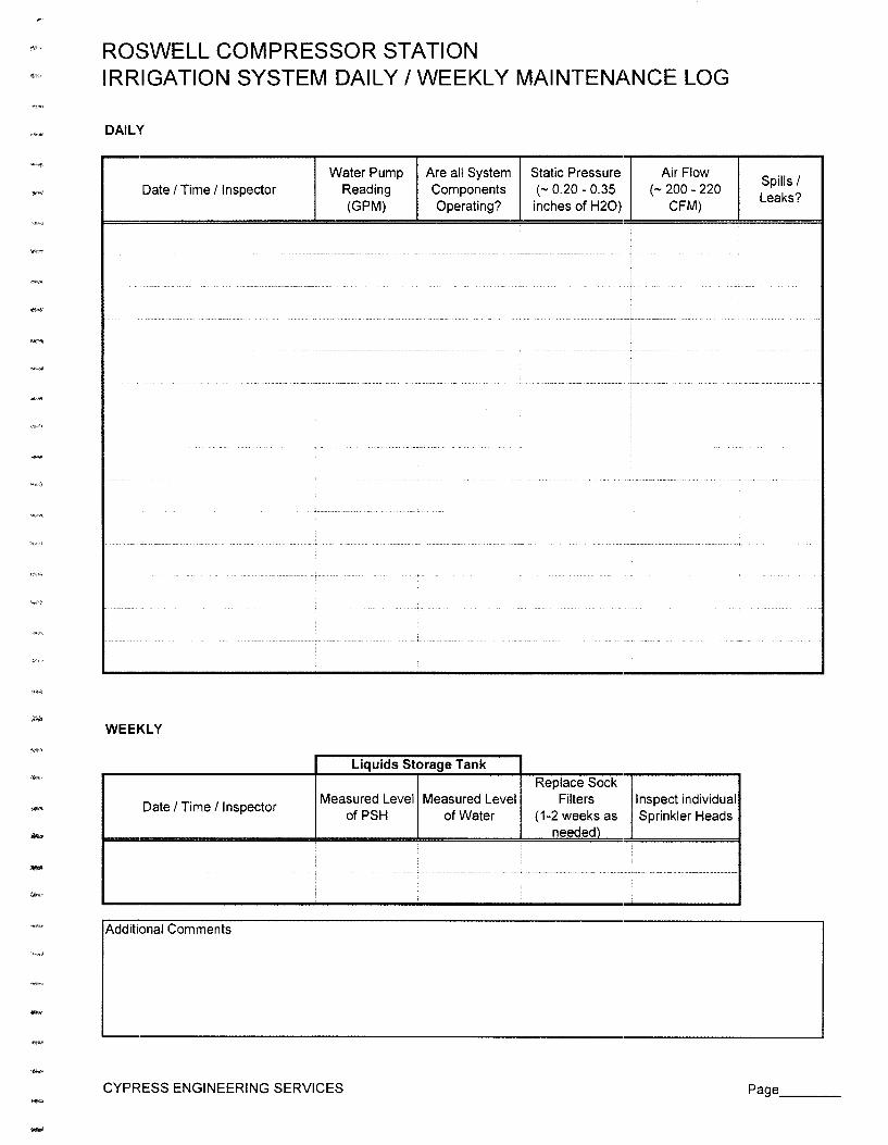
-
ROSWELL COMPRESSOR STATION IRRIGATION SYSTEM DAILY /WEEKLY MAINTENANCE LOG
DAILY
Date I Time / Inspector
WEEKLY
Date I Time/ Inspector
.....
Additional Comments
Water Pump Reading (GPM)
Are all System Components Operating?
Liquids Storage Tank
Measured Level Measured Level of PSH of Water
CYPRESS ENGINEERING SERVICES
Static Pressure (- 0.20 - 0.35 inches of H20)
Replace Sock Filters
( 1-2 weeks as needed)
.)__ _____ _
Air Flow (- 200 - 220
CFM)
Inspect individual Sprinkler Heads
·-··
Spills I Leaks?
Page __ _

ROSWELL COMPRESSOR STATION AIR. COMPRESSOR DAILY I WEEKLY MAINTENANCE LOG
DAILY
Date I Time/ Inspector Maintain oil Check oil Drain Oil
Oil Filter at 1 /3 level return line Condensate Separator in site tube for oil flow seperator (psi) (psi)
WEEKLY
Inspect air Check heat Tighten Drain Check
Date I Time / Inspector inlet filter Check belt exchanger loose Drain air condensate load I
element tension for fittings.& receiver from oil unload
cleanliness fasteners sumo Cvcle
----,~- . -~- ·-----------------·- -- ----·- ··-------- ........ ____ '""""" ----- - . """"
l ! i
Additional Comments
CYPRESS ENGINEERING SERVICES Page __ _

--
-
ROSWELL COMPRESSOR STATION BAKER FURNACE SEMI-ANNUAL I ANNUAL MAINTENANCE LOG WEST UNIT (Serial No. 285); NMED Air Permit No. 1777
MONTHLY
Date I Time / Inspector
SEMI-ANNUAL
Date I Time / Inspector
-·---~---·- .. ,,_,_,, _______________ " -----·--·--~----- -
Additional Comments
Total Hours of Grease Operation Bearings
L __ i i
Total Hours of Operation
Replace Oil
CYPRESS ENGINEERING SERVICES
Check Be,lts Check Air Filter
Replace Air Replace Belts Filter (as needed)
------- ..... _.,_ - ... -._. _______________
Page __ _

--....
-
ROSWELL COMPRESSOR STATION BAKER FURNACE SEMI-ANNUAL I ANNUAL MAINTENANCE LOG EAST UNIT (Serial No. 286); NMED Air Permit No. 1 ~776
MONTHLY
Date I Time I Inspector Total Hours of Grease
Check Belts Check Air Filter Operation Bearings
:
' .
SEMI-ANNUAL
Date I Time I Inspector Total Hours of
Replace Oil Replace Air Replace Belts
Operation Filter (as needed)
. '
Additional Comments
CYPRESS ENGINEERING SERVICES Page __ _

--
ROSWELL COMPRESSOR STATION AIR COMPRESSOR SEMI-ANNUAL I ANNUAL MAINTENANCE LOG
SEMI-ANNUAL
Date I Time / Inspector
ANNUAL
Date I Time/ Inspector
Additional Comments
Check motor/compressor V-belt alignment
Change Lubricant
CYPRESS ENGINEERING SERVICES
(
Change Air Change Filter Lubricant Filter
Change Oil/Air Separator Element
I
Page __ _