Embed Size (px)
Citation preview

SG2X Vibrator Motor
Issued 12 Jun 09 Rev 15 Dec 15
Maintenance & Operation Manual
DISCLAIMER
Derrick Corporation has taken care to ensure that all of its maintenance and operation manuals are accurate. However, we offer no guarantees or warranties in this regard. Our manuals are provided only as a guide to assist with the maintenance and operation. Derrick Corporation takes no responsibility for any losses, damage, or injuries that may occur as a result of using any of our manuals.
It is ultimately the operator’s responsibility to ensure that the operation, repair, and maintenance of equipment complies with all applicable national and local regulations, including safety regulations.
THIS MANUAL IS PROVIDED BY DERRICK CORPORATION ON AN “AS IS” BASIS AND DERRICK CORPORATION EXPRESSLY DISCLAIMS ANY AND ALL WARRANTIES, EXPRESS OR IMPLIED, INCLUDING WITHOUT LIMITATION WARRANTIES OF MERCHANTABILITY AND FITNESS FOR A PARTICULAR PURPOSE. IN NO EVENT SHALL DERRICK CORPORATION BE LIABLE FOR ANY DIRECT, INDIRECT, INCIDENTAL, PUNITIVE, OR CONSEQUENTIAL DAMAGES OF ANY KIND WHATSOEVER WITH RESPECT TO THE MANUAL AND EQUIPMENT.
Derrick Equipment Company 15630 Export Plaza Drive
Houston, Texas 77032 Phone: 281.590.3003
Toll Free: 1.866.DERRICK Fax: 281.442.6948
www.derrickequipment.com


PRODUCT SUPPORT Derrick offers 24-hour-per-day, 7-day-per-week product support for repair, parts, and service. Refer to the following table for the parts/service center nearest you.
PARTS SALES & SERVICE LOCATIONS
Colorado
Grand Junction - 970.241.2417
Louisiana
Broussard - 877.635.3354
New York - Corporate Headquarters
Buffalo - 716.683.9010
Oklahoma
Oklahoma City - 405.208.4070
Texas
Houston (Oilfield Headquarters) - 866.DERRICK (337.7425) 281.590.3003
North Texas (Bridgeport) - 405.208.4070
South Texas (Corpus Christi) - 361.299.6080
West Texas (Midland) - 405.397.4089
East Texas, Arkansas, and Louisiana - 281.546.1166
Wyoming
Casper - 307.265.0445
North Dakota
Williston - 701.572.0722
This document contains proprietary information of Derrick Corporation. It is intended solely for the information and use of parties operating and maintaining the equipment described herein. Such proprietary information may not be used, reproduced, or disclosed to any other parties for any other purpose without the expressed written permission of Derrick Corporation. Continuous improvement is a policy of Derrick Corporation. All instructions and procedures are subject to change without notice.


CONTENTS SG2X VIBRATOR MOTOR
15 Dec 12 TOC
Page Description ............................................................................................................. 1 Repair Restrictions................................................................................................. 2 Safety .................................................................................................................... 2 Storage .................................................................................................................. 3 Operating Environment .......................................................................................... 3 Replacement Parts ................................................................................................ 3 Removal and Installation ........................................................................................ 5 Electrical Connections ........................................................................................... 9 Preventive Maintenance ........................................................................................ 13 Oil Change Procedure ........................................................................................... 14 Bearing Replacement ............................................................................................ 16 Troubleshooting ..................................................................................................... 29


SG2X VIBRATOR MOTOR
15 Dec 12 1
DESCRIPTION Motion generated by the explosion-proof SG2X vibrator motors is transmitted to the screen frame to separate and convey solids over the screen panels. The motors are rated for continuous duty with Totally Enclosed Non-Ventilated (TENV) construction and oil-bath lubricated bearings. To maximize the G-forces produced by the vibrator motors, they are attached directly to the screen frame and are positioned over the screening bed.
Eccentric weights installed on the rotor shaft produce the motor’s vibratory action. The weight, which is measured in in-lbs, varies depending on the application and equipment on which the vibrator motor is installed. The weight is stamped on the motor nameplate. When two vibrator motors are installed on a single screen frame, the motors are connected to cause the motors to rotate in opposite directions for maximum G-forces.
The vibrator motors must be operated at their rated three-phase supply voltage. The model designation shown on the nameplate is defined as follows:
SG2 X 30 – 18 – 460/480 – 6 000
Factory-Assigned Options Code Supply Voltage Frequency 5 - 50Hz 6 - 60Hz Operating Voltage RPM (x 100) Eccentric Weight (in-lbs) per Side Construction: X - Explosion-Proof SG2 Motor

SG2X VIBRATOR MOTOR
2 15 Dec 12
REPAIR RESTRICTIONS The Derrick SG2X motor has a CLASS I (flammable gas atmosphere) certification, which restricts the user to replacing only the following parts: • Bearings • Outer eccentric weights • Power cord • Junction box components
To maintain the flameproof rating of the motor, no parts beyond the bearing may be removed.
Also, while under warranty, no repairs of any kind are permitted; the motor may not be opened for any reason. If the motor fails while under warranty, contact the Derrick Service department for assistance. The warranty will be void, if it is determined that the motor has been opened during the warranty period.
Caution! Contact The Derrick Service Department If Motor Fails During The Warranty Period. All Warranties, Whether Stated Or Implied, Will Be Null And Void If The Motor Is Opened During The Warranty Period. Derrick Corporation May Not Be Held Responsible For Any Liabilities Incurred During, Or As A Result Of, Unauthorized Repair Attempts.
SAFETY Successful and safe operation of all industrial machinery, including Derrick vibrators, requires proper handling, installation, operation, and maintenance. Failure to follow installation and maintenance requirements may result in personal injury, equipment failure, or property damage.
Only trained, qualified personnel should be involved in the installation, operation, and maintenance procedures. All plant safety procedures must be observed. Qualified personnel must be familiar with the construction, installation, maintenance, and operation of the equipment and must be aware of any hazards associated with operation of the equipment. In addition, personnel must be trained and authorized to energize, de-energize, clear, ground, and tag circuits and equipment in accordance with established safety practices and be trained in proper care and use of personal protective equipment in accordance with established safety practices.
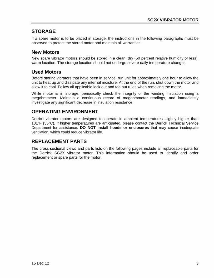
DANGER! HIGH VOLTAGE. SHUT DOWN, LOCK OUT, AND TAG OUT ELECTRIC POWER BEFORE WORKING ON THIS EQUIPMENT.
WARNING! ALL DERRICK VIBRATOR MOTORS MUST BE INSTALLED AND GROUNDED IN ACCORDANCE WITH ALL APPLICABLE NATIONAL, STATE, AND LOCAL ELECTRICAL CODES.
WARNING! HOT SURFACE. DO NOT TOUCH MOTOR HOUSING DURING OR IMMEDIATELY AFTER OPERATION.
SG2X VIBRATOR MOTOR
15 Dec 12 3
STORAGE If a spare motor is to be placed in storage, the instructions in the following paragraphs must be observed to protect the stored motor and maintain all warranties.
New Motors New spare vibrator motors should be stored in a clean, dry (50 percent relative humidity or less), warm location. The storage location should not undergo severe daily temperature changes.
Used Motors Before storing vibrators that have been in service, run unit for approximately one hour to allow the unit to heat up and dissipate any internal moisture. At the end of the run, shut down the motor and allow it to cool. Follow all applicable lock out and tag out rules when removing the motor.
While motor is in storage, periodically check the integrity of the winding insulation using a megohmmeter. Maintain a continuous record of megohmmeter readings, and immediately investigate any significant decrease in insulation resistance.
OPERATING ENVIRONMENT Derrick vibrator motors are designed to operate in ambient temperatures slightly higher than 131°F (55°C). If higher temperatures are anticipated, please contact the Derrick Technical Service Department for assistance. DO NOT install hoods or enclosures that may cause inadequate ventilation, which could reduce vibrator life.
REPLACEMENT PARTS The cross-sectional views and parts lists on the following pages include all replaceable parts for the Derrick SG2X vibrator motor. This information should be used to identify and order replacement or spare parts for the motor.

SG2X VIBRATOR MOTOR
4 15 Dec 12
REPLACEMENT PARTS (CONT’D)
Ref
. Dw
g. 1
5567

SG2X VIBRATOR MOTOR
15 Dec 12 5
SG2X MOTOR REPLACEMENT PARTS
No. Part No. Description Qty
1 G0004163 Plug, O-Ring Boss, .875-14, Zpl-Stl 2
2 15697-01 Spacer, Bearing, A6061 T651 Al 2
3 G0004742 O-Ring, .680 ID x .070 Cross Section, 75 Duro Viton, Drain 2
4 G0003195 Bolt, Hex Skt Hd, M8-1.25 x 65MM, Aly Stl W/Nylon Patch 12
5 G0001960 Bearing 2
6 G0003627 O-Ring, 5.25 ID x .070 Cross Section, 75 Duro Viton 1
7 11006-00-001 Junction Box Assembly 1
8 15533-01-001 Junction Box Cover 1
9 14226-01 Mount, Bearing 2
10 15301-01 Washer, Oil Dam, Shaft 4140 Aly Stl 2
11 15042-00-001 Cover Plate, Oil Reservoir 2
12 G0004162 Plug, O-Ring Boss, .500-20, Zpl Stl 4
13 G0008039 O-Ring, 6.237 ID x .103 Cross Section, Viton, Cover Plate 2
14* 15699-00* Motor Weight(s), Outer* A/R
15 G0005067 O-Ring, 8.519 ID x .070XS, Viton, Brng Hsng to Reservoir 2
16 15559-00-001 Reservoir, Oil 2
17 G0002315 Nipple, Toe, .125 NPT x 2.75 Sch 40 2
18 15534-01 Cup, Oil Return, 319 Al 2
19 G0007047 Bolt, Hex Skt, M6-1.0 x 20MM 12
20 G0005059 Block, Cord Retainer, 6061 T6 Al 1
21 G0004743 Grommet, Cord, .750 ID 1
22 G0002266 Bolt, Hex Skt Hd, M6, 1.0 x 16mm, SST W/Nylon Patch 6
23 SKPP-75 Plug, Pipe, .750 NPT W/Hex Skt, Zpl Stl 1
* Include serial number with order
REMOVAL AND INSTALLATION The removal and installation procedures below include photos for a typical motor. While the motor appearance may vary, these differences do not affect removal and installation.

SG2X VIBRATOR MOTOR
6 15 Dec 12
Tool Kit A tool kit containing all necessary equipment for removing and installing motor mounting studs is available from Derrick. The kit part number and components are as follows:
Part No. Description Kit No. G0003029 - 3/4” Hex Head Bolt G0002020 Torque Wrench, 200-600 ft-lbs, 3/4” Drive
G0003026 Extension, 3/4” Drive x 8” Lg
G0003027 Deep Socket, 3/4” Drive x 1-1/8”
G0003028 Box End Wrench, Offset, 1-1/8”
G0003030 Breaker Bar, 3/4”
Safety Be sure to follow the warnings listed below before, during, and after the removal or installation of the vibrator motor.
DANGER! HIGH VOLTAGE. SHUT DOWN, LOCK OUT, AND TAG OUT ELECTRIC POWER BEFORE WORKING ON THIS EQUIPMENT.
WARNING! HOT SURFACE. DO NOT TOUCH MOTOR HOUSING DURING OR IMMEDIATELY AFTER OPERATION.
WARNING! BE SURE THAT HANDLING DEVICES HAVE SUFFICIENT LIFTING CAPACITY TO SAFELY HANDLE THE WEIGHT OF THE EQUIPMENT.
Caution! Screen Panels Will Be Damaged If Struck By Hardware Or Tools. Either Remove Screen Panels Or Protect From Damage During Motor Removal Or Installation.
Caution! Motor May Be Damaged By Storing In A High-Humidity Environment (Greater Than 50% RH). Out-Of-Service Motor(S) Must Be Stored In A Low-Humidity Environment.
Motor Handling 1. When lifting motor, position lifting sling at the center of the motor case (Figure 1).
2. DO NOT PINCH MOTOR POWER CORD WHEN INSTALLING LIFTING SLING. To prevent damage to power cord when lifting motor assembly, always keep sling next to motor case.

SG2X VIBRATOR MOTOR
15 Dec 12 7
Figure 1. Hoisting Sling Position
Mounting Hardware Installation
Caution! Due To High Torque Applied During Installation, Re-Use Of Motor Mounting Hardware Is Not Recommended. All Hardware Components Should Be Replaced Whenever A Motor Is Removed.
The vibrator motors are secured with 3/4” studs installed from either side of the screen frame (Figure 2). Hardened washers are installed under both nuts as shown.
Figure 2. Motor Mounting Stud Installation

SG2X VIBRATOR MOTOR
8 15 Dec 12
Motor Positioning and Mounting
1 - Using overhead lifting device, position vibrator motor over screen frame.
2 - Insert stud with nut and hardened washer from top of motor. Lower motor onto screen frame, and insert stud through screen frame.
3 - Install hardened washer and nut on each stud. Restrain nut on top while tightening nut from underside of screen frame.
4 - Use a 1-1/8” wrench to restrain nut on top while using a torque wrench with a 1-1/8” deep socket to tighten nut to 250 ft lbs (339 Nm).
SG2X VIBRATOR MOTOR
15 Dec 12 9
ELECTRICAL CONNECTIONS The following instructions are to be used when replacing a motor and/or electric power cord on a Derrick machine. To ensure that connections are correct, always tag leads for identification before disconnecting.
The Derrick vibrator motor must be operated at the specified voltage and frequency. Refer to the data plate on the motor case for the motor’s voltage and frequency requirements. Prior to installing the vibrator motor, verify that the electrical power configuration corresponds to the electrical requirements specified on the motor.
Safety Electrical connections should be performed only by trained, qualified personnel familiar with high-voltage applications and knowledgeable of National Electrical Code (NEC) standards and all other national, state, or local codes applicable to installation of industrial equipment.
DANGER! HIGH VOLTAGE. SHUT DOWN, LOCK OUT, AND TAG OUT ELECTRIC POWER BEFORE WORKING ON THIS EQUIPMENT.
WARNING! ALL ELECTRICAL CONNECTIONS MUST COMPLY WITH NATIONAL, STATE, AND LOCAL ELECTRICAL CODES. FAILURE TO COMPLY MAY RESULT IN AN UNSAFE CONDITION THAT COULD INJURE PERSONNEL OR DAMAGE EQUIPMENT. ENSURE THAT ALL ELECTRICAL AND CONDUIT CONNECTIONS ARE SECURE.
WARNING! BE SURE THAT MOTOR IS PROPERLY GROUNDED.
WARNING! HOT SURFACE. DO NOT TOUCH MOTOR HOUSING DURING OR IMMEDIATELY AFTER OPERATION.
Caution! Motor May Be Damaged By Incorrect Supply Power. Be Sure That Voltage And Frequency Are Within ±10% Of Motor Data Plate Specifications.
Caution! Screen Panels Will Be Damaged If Struck By Hardware Or Tools. Either Remove Screen Panels Or Protect From Damage During Motor Removal Or Installation.
Caution! Motor May Be Damaged If Stored In A High-Humidity Environment (Greater Than 50% RH). Be Sure That Motor Was Stored In A Low-Humidity Environment.
SG2X VIBRATOR MOTOR
10 15 Dec 12
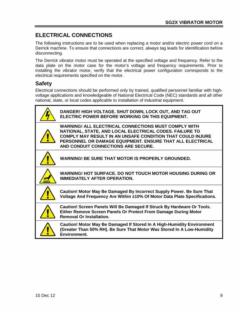
Connections To Motor Junction Box If replacing a cable, tag all leads for identification before disconnecting old cable. Beginning with serial number SG2-3443, the motor cord is connected to a plug-in female receptacle instead of the terminal block that was formerly used for these connections. The cord leads are fed through the junction box cover and connected to the receptacle, which mates with a male plug in the motor junction box.
To connect motor cord to power connector, proceed as follows:
1. Remove cover from motor junction box, and discard O-ring (Figure 3).
Figure 3. Motor Cord Connections to Power Connector
2. Insert motor cord leads through junction box cover.
3. Apply anti-seize compound to front gland nut, and install and tighten in threaded opening in cover.
4. Install remaining gland components, and tighten backnut only sufficiently to cause red seal to begin to protrude. Do not over-tighten backnut.
5. Match leads to power connector labels, and connect leads to terminals as shown.
6. Apply small amount of LubriPlate 5555, part number L0107-007, or UL-approved equivalent, to new O-ring, and install O-ring in groove of cover.
7. Align cover mounting holes with holes in junction box (Figure 4), ensure that O-ring remains in place, and install cover by engaging power connector plug and receptacle.

SG2X VIBRATOR MOTOR
15 Dec 12 11
Figure 4. Mating Power Connector with Motor Junction Box
Note! Be sure that connector halves mate easily and that O-ring remains in place during assembly.
8. Secure cover to junction box with four socket head cap screws, and tighten screws to 250 in lbs (28.2 Nm).
9. Check for proper fit between cover and junction box surface by attempting to insert a 0.001” shim between the two parts around the entire mating area circumference. If the shim can be inserted at any location, unplug the cover and correct any defect.
Connections To Control Panel Motor leads are connected to thermal overloads inside the electrical control panel. Before disconnecting and removing old cable, tag all leads for identification. In addition to the following procedure, refer to the schematic diagram in Section 8 of your equipment manual to confirm proper connections.
1. Wrap leads loosely with electrical tape to facilitate threading through elbows.
2. Pass leads through elbows and into control panel (Figure 5).
3. Thread front gland nut into elbow, and tighten securely. Thread rear gland nut onto front gland nut, and tighten securely. Thread and tighten backnut onto cable gland.
4. Connect power leads to starter overload terminals inside control panel. Typical connections are shown in Figure 6. Due to variations, however, actual connections on your equipment may be different (refer to the schematic diagram in Section 8 of your equipment manual).

SG2X VIBRATOR MOTOR
12 15 Dec 12
Motor Cord Power Connections To Control Panel (Cont’d)
Figure 5. Typical Motor Cord and Gland Installation in Control Panel
Figure 6. Typical Motor Connections to Starter Overloads

SG2X VIBRATOR MOTOR
15 Dec 12 13
Motor Thermal Switch Connections The blue and orange leads from the normally closed (N.C.) contacts of the motor’s thermal switch may be connected to a customer-supplied indicator to provide a visual indication of normal motor temperature. Alternatively, the switch may be wired to shut down the motor in case of overheating. If the motor overheats, the N.C. contacts will open. Depending on wiring configuration, this will either turn off the indicator or shut down the motor. If the thermal switch connection is to be used, refer to the electrical schematic diagram in Section 8 of your equipment manual for guidance in connecting the switch leads.
Motor Test After completing the electrical connections, test the motor to confirm proper operation. Check that motors rotate in opposite directions. If the motor test reveals that motors are rotating in the same direction, reverse the leads of one motor to correct the direction of rotation.
PREVENTIVE MAINTENANCE Routine maintenance will ensure maximum life for the vibrator motor. While the maintenance schedule in this section is not rigid, modifications should be based on operating experience at your facilities. A maintenance log will help establish and monitor a service schedule that is correct for your equipment. The maintenance log should contain the following information: • Motor model and serial number from motor data plate • Power requirements • Voltage readings: L1 to L2, L1 to L3, and L2 to L3 • Amperage readings: L1 to L2, L1 to L3, and L2 to L3
DANGER! HIGH VOLTAGE. SHUT DOWN, LOCK OUT, AND TAG OUT ELECTRIC POWER BEFORE WORKING ON THIS EQUIPMENT.
WARNING! HOT SURFACE. WEAR HEAT-RESISTANT GLOVES WHEN WORKING NEAR MOTOR DURING OR IMMEDIATELY AFTER OPERATION.
VIBRATOR MOTOR MAINTENANCE
Maintenance Action Frequency
Clean process material from exterior of motor case*. Daily or as required
Inspect motor cable for signs of deterioration or damage. Each shift or as required
Using a torque wrench, verify that motor mounting bolt torque is in accordance with torque listed in Motor Removal and Installation.
After first 40 hours of operation; then once each year
Change lubricating oil when bearings are replaced. Refer to Oil Change Procedure. At time of bearing replacement
* The vibrator motor is designed to dissipate heat through the motor case. Buildup of process material on the motor case exterior prevents proper heat dissipation and may cause the motor to overheat.

SG2X VIBRATOR MOTOR
14 15 Dec 12
OIL CHANGE PROCEDURE The oil should be changed when bearings are replaced. The following paragraphs describe the approved oils and the draining and filling procedure.
Safety
DANGER! HIGH VOLTAGE. SHUT DOWN, LOCK OUT, AND TAG OUT ELECTRIC POWER BEFORE WORKING ON THIS EQUIPMENT.
WHEN DRAINING AND RE-FILLING MOTOR, PROTECT PROCESS MATERIAL AND ENVIRONMENT FROM OIL CONTAMINATION. DISPOSE OF USED OIL IN ACCORDANCE WITH ALL APPLICABLE FEDERAL, STATE, AND LOCAL REGULATIONS.
Approved Oils The vibrator motor is filled at the factory with Chevron GST ISO 68 Turbine oil. This product is suitable for temperatures ranging from ≤20°F to ≥104°F (≤-7°C to ≥40°C). Only equivalent products may be used in the motor. Synthetic oils are not recommended as they may contain additives that could adversely affect motor life.
Caution! To Prevent Damage To Motor, Use Only Approved Lubricating Oil. Confirm That Any Alternative Product Is Equivalent To Chevron GST ISO 68 Turbine Oil.
Draining Oil 1. Verify that the equipment has been de-energized and locked out and tagged out. 2. Read and understand all safety information presented in this section before performing the
maintenance procedure. 3. Spread protective plastic sheet, or equivalent, directly below machine-mounted vibrator motor.
Protective sheet must be large enough to protect process material and surrounding environment from contamination by lubricating oil during draining and re-filling.
4. Place a suitable container below one drain plug to receive used oil (Figure 7). Each end of motor contains 1.5 quarts (1.42 liters), for a total of 3 quarts (2.84 liters).To avoid spillage, the container should have a capacity of at least 1.75 quarts (1.7 liters).
5. To facilitate draining, the motor should be vented by removing the oil fill plug from one end. To assist in loosening the plug, tap lightly with a 14-ounce hammer; then use a 3/8” hex bit to unscrew plug.
6. To remove drain plug from one side of the motor, tap lightly with a 14-ounce hammer; then use a 3/16” hex bit to unscrew plug. Allow oil to drain completely, and then re-install drain plug.
7. Repeat steps 4 through 6 for the opposite end of the motor. 8. Dispose of waste oil properly.

SG2X VIBRATOR MOTOR
15 Dec 12 15
Figure 7. Oil Drain and Fill Plugs
Re-Filling 1. Using a funnel, fill each end of the motor with 1.5 quarts (1.42 liters) of Chevron GST ISO 68
Turbine oil or equivalent product.
2. Re-install and tighten oil fill plug.
3. Confirm that oil level is at the level plug on the cover plate.
4. Repeat steps 1 through 3 for opposite end of motor.
Note! Oil level should be at level plug on the cover plate after motor is run about 30 minutes. Oil level is satisfactory as long as it remains at the level plug.
BEARING REPLACEMENT The following bearing replacement procedure applies only to SG2X motors that are no longer under warranty. During the warranty period the motor is not to be opened for any reason, as this will void the warranty. Contact the Derrick Service department for assistance if a motor fails while under warranty.
Note! All warranties, whether stated or implied, will be void if the Derrick motor is opened during the warranty period.
SG2X VIBRATOR MOTOR
16 15 Dec 12
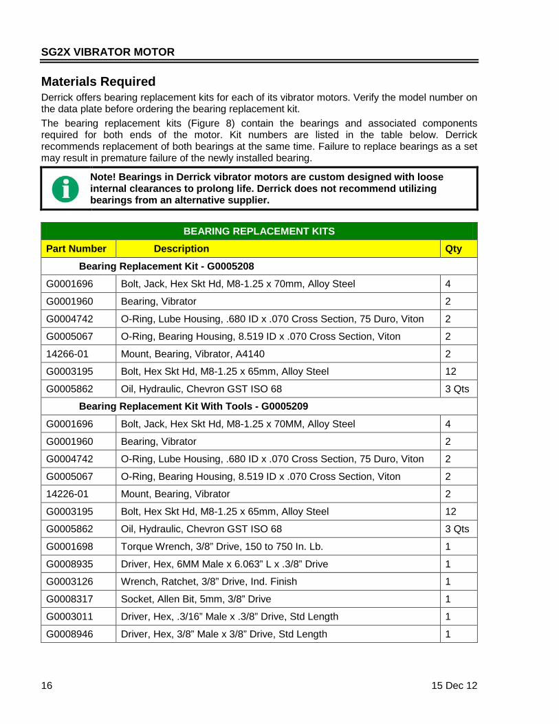
Materials Required Derrick offers bearing replacement kits for each of its vibrator motors. Verify the model number on the data plate before ordering the bearing replacement kit. The bearing replacement kits (Figure 8) contain the bearings and associated components required for both ends of the motor. Kit numbers are listed in the table below. Derrick recommends replacement of both bearings at the same time. Failure to replace bearings as a set may result in premature failure of the newly installed bearing.
Note! Bearings in Derrick vibrator motors are custom designed with loose internal clearances to prolong life. Derrick does not recommend utilizing bearings from an alternative supplier.
BEARING REPLACEMENT KITS
Part Number Description Qty
Bearing Replacement Kit - G0005208
G0001696 Bolt, Jack, Hex Skt Hd, M8-1.25 x 70mm, Alloy Steel 4
G0001960 Bearing, Vibrator 2
G0004742 O-Ring, Lube Housing, .680 ID x .070 Cross Section, 75 Duro, Viton 2
G0005067 O-Ring, Bearing Housing, 8.519 ID x .070 Cross Section, Viton 2
14266-01 Mount, Bearing, Vibrator, A4140 2
G0003195 Bolt, Hex Skt Hd, M8-1.25 x 65mm, Alloy Steel 12
G0005862 Oil, Hydraulic, Chevron GST ISO 68 3 Qts
Bearing Replacement Kit With Tools - G0005209
G0001696 Bolt, Jack, Hex Skt Hd, M8-1.25 x 70MM, Alloy Steel 4
G0001960 Bearing, Vibrator 2
G0004742 O-Ring, Lube Housing, .680 ID x .070 Cross Section, 75 Duro, Viton 2
G0005067 O-Ring, Bearing Housing, 8.519 ID x .070 Cross Section, Viton 2
14226-01 Mount, Bearing, Vibrator 2
G0003195 Bolt, Hex Skt Hd, M8-1.25 x 65mm, Alloy Steel 12
G0005862 Oil, Hydraulic, Chevron GST ISO 68 3 Qts
G0001698 Torque Wrench, 3/8” Drive, 150 to 750 In. Lb. 1
G0008935 Driver, Hex, 6MM Male x 6.063” L x .3/8” Drive 1
G0003126 Wrench, Ratchet, 3/8” Drive, Ind. Finish 1
G0008317 Socket, Allen Bit, 5mm, 3/8” Drive 1
G0003011 Driver, Hex, .3/16” Male x .3/8” Drive, Std Length 1
G0008946 Driver, Hex, 3/8” Male x 3/8” Drive, Std Length 1

SG2X VIBRATOR MOTOR
15 Dec 12 17
Figure 8. Bearing Replacement Kit Components (Without Tool Kit)
Tools Required Following is a recommended tool list for use during the bearing replacement procedure: • Torque wrench, 100 to 300 in lbs (11.3 to 34 Nm) • Hex wrench, 5mm • Hex wrench, 6mm • Hex wrench, 3/16” • Hex wrench, 3/8” • Hammer • Dental pick or similar tool • Clean, absorbent cloths • Safety glasses • Heat resistant gloves, 250°F (121°C) or higher • Welder’s torch • Bearing heater
Work Area Environment Derrick Corporation recommends the following work area environment:
1. Well-lighted area with sufficiently large work-surface area to accomplish the required tasks.
2. Clean work surface to prevent contamination of the new bearings and motor interior.

SG2X VIBRATOR MOTOR
18 15 Dec 12
Safety The following WARNINGS relate to the bearing replacement procedure. Be sure to read and understand these WARNINGS before proceeding.
DANGER! HIGH VOLTAGE. SHUT DOWN, LOCK OUT, AND TAG OUT ELECTRIC POWER BEFORE WORKING ON THIS EQUIPMENT.
WARNING! HOT SURFACE. DO NOT TOUCH MOTOR HOUSING DURING OR IMMEDIATELY AFTER OPERATION.
WARNING! SAFETY GLASSES MUST BE WORN DURING BEARING REPLACEMENT PROCEDURES. FAILURE TO WEAR SAFETY GLASSES MAY RESULT IN SERIOUS EYE INJURY OR PERMANENT LOSS OF VISION.
WARNING! ALL OPERATING AND MAINTENANCE PERSONNEL MUST READ AND UNDERSTAND ALL SAFETY INFORMATION IN THIS MANUAL BEFORE WORKING WITH THE EQUIPMENT.
Bearing Replacement Procedure Bearing replacement consists of bearing removal and installation. The procedures for replacing one bearing are presented below. Repeat these procedures for the second bearing.
Note! The vibrator motor must be removed from the equipment before performing bearing replacement. Refer to Removal and Installation.
Note! Keep bearings in a clean area until ready for installation. Premature bearing failure will occur if replacement bearings become contaminated during bearing replacement procedure.
Bearing Removal The following procedure describes bearing removal for one side of the motor. Repeat the procedure to remove bearing at opposite end.

SG2X VIBRATOR MOTOR
15 Dec 12 19
1 - Remove motor from the equipment and position in a cradle with the oil drain plugs at the bottom of the motor. Place a suitable container beneath drain plug.
2 - Tap drain and fill plugs lightly with a 14 oz. hammer to facilitate removal. To vent the motor, remove fill plug using a 3/8” hex wrench; then use a 3/16” hex wrench to remove drain plug. Allow oil to drain fully. Discard waste oil properly.
3 - If motor has 60 in lb eccentric weights (refer to identification tag), the weight will interfere with housing removal. To prevent this interference, remove oil return cup as described in steps 3a and 3b. If eccentric weights are less than 60 in lb, skip to step 4.

SG2X VIBRATOR MOTOR
20 15 Dec 12
Bearing Removal (Cont’d)
3a - Remove six M6 screws securing cover plate to oil reservoir, and remove plate. Retain O-ring.
3b - Working through reservoir opening, remove six M6 screws securing oil return cup to interior of reservoir, and remove cup and O-ring. Retain O-ring.
4 - Using a 6mm hex wrench, remove eight M8 screws securing oil reservoir to bearing housing, being sure to support cover as last screw is being removed.
5 - Carefully slide off reservoir and set aside.

SG2X VIBRATOR MOTOR
15 Dec 12 21
6 - Using a 6mm hex wrench, loosen socket head set screw securing outboard eccentric weight(s) to motor shaft. Note that more than one outboard eccentric weight may be installed.
7 - Remove outboard eccentric weight(s) from motor shaft. Then, using a soft absorbent cloth, remove excess lubricant from components. Do not use compressed air to remove lubricant.
8 - Remove reservoir O-ring and bearing housing O-ring (arrow). If necessary, use a dental pick or other tool to free a compacted ring. Discard both O-rings.
9 - Slide the spacer off the motor shaft and set aside. If spacer is not easily removed, gently heat spacer for about 5 seconds to facilitate removal.

SG2X VIBRATOR MOTOR
22 15 Dec 12
Bearing Removal (Cont’d)
10 - Using a 6mm hex wrench, remove six M8 screws securing bearing mount to bearing housing.
11 - Identify two threaded holes that accept M8-1.25x70 socket head jack bolts. The jack bolt holes are 180° apart as shown.
12 - Carefully thread jack bolts into threaded holes in bearing mount, being sure to avoid cross-threading.
13 - Using a 6mm hex wrench, alternately and equally advance each jack bolt a few turns at a time to extract bearing mount from housing.

SG2X VIBRATOR MOTOR
15 Dec 12 23
14 - Remove and discard bearing and bearing mount.
15 - Using a soft absorbent cloth, remove excess lubricant from interior of bearing housing and inner bearing race. Do not use compressed air for cleaning, as this may drive contaminants into motor.
16 - A bearing puller is recommended for removing inner bearing race. If puller is not available, use a torch with a diffused flame to heat inner bearing race to approximately 200°-230°F (93°-110°C). Typically, heating requires less than 10 seconds to expand the inner bearing race for removal.
17 - Carefully remove and discard heated inner bearing race from motor shaft. Using a soft absorbent cloth, remove excess lubricant from interior of bearing housing.

SG2X VIBRATOR MOTOR
24 15 Dec 12
Bearing Installation
1 - Wipe excess lubricant from new inner bearing race and, using a bearing heater or oil bath heater, heat inner bearing race to approximately 230°F (110°C). Be careful to avoid contaminating these components.
2 - Slide heated inner bearing race onto motor shaft until shoulder of race contacts bearing seat in rear of cavity.
3 - Lightly lubricate surface of inner bearing race and wall of bearing housing.
4 - Select any two clearance holes (NOT threaded) in bearing mount that are 180° apart. Insert two M8-1.25x70 jack bolts through the clearance holes.

SG2X VIBRATOR MOTOR
15 Dec 12 25
5 - Visually align the open clearance holes in bearing mount with threaded holes in bearing housing. Thread jack bolts into holes in bearing housing.
6 - Alternately advance jack bolts a few turns at a time until bearing mount is drawn securely into bearing housing. Remove both jack bolts.
7 - Secure bearing mount by installing six M8-1.25x65 socket head cap screws in the clearance holes; hand-tighten screws.
8 - Using a torque wrench and 6mm hex bit, alternately tighten all six bearing mount cap screws to 250 in lbs (28.2 Nm).

SG2X VIBRATOR MOTOR
26 15 Dec 12
Bearing Installation (Cont’d)
9 - Position spacer on motor shaft, and slide spacer into bearing.
10 - Lightly lubricate and install both main cover O-ring and oil drain O-ring.
11 - Orient eccentric weight(s) with split facing Derrick logo on motor case and pin on inside of weight aligned with keyway of motor shaft. If two weights are used, install heaviest weight closest to bearing mount.
12 - Using a torque wrench and 6mm hex wrench, tighten M8 cap screw(s) to 250 in lbs (28.2 Nm).

SG2X VIBRATOR MOTOR
15 Dec 12 27
13 - Check for free rotation of motor shaft by rotating the eccentric weight(s) several revolutions in both directions. If any binding is detected, disassemble motor and correct defect(s).
14 - Check axial play of motor shaft by pushing and pulling eccentric weight(s). Axial movement shall be 1/16” to 1/8” (1.6 to 3.2mm). If movement is excessive, disassemble motor and correct defect(s).
15 - Position oil reservoir on bearing housing, using care to avoid pinching O-ring (arrow). Orient cover with fill plug aligned with lifting lug, and install and hand-tighten six M8 screws.
16 - Using a torque wrench and a 6mm hex bit, tighten screws to 250 in lbs (28.2 Nm).

SG2X VIBRATOR MOTOR
28 15 Dec 12
Bearing Installation (Cont’d)
17a - If oil return cup was removed, install O-ring on cup and position cup on interior of reservoir. Align cup opening with lifting lug on motor case, and secure with six M6 screws tightened to 115 in lbs (13 Nm).
17b - Install cover plate O-ring in reservoir groove. Place cover plate on reservoir, and secure with six M6 screws tightened to 115 in lbs (13 Nm).
18 - Install oil drain plug, and tighten to 100 in lbs (11.3 Nm).
19 - Fill each reservoir with approximately 1.5 quarts (1.4 liters) of approved fresh oil, and then install and tighten oil filler plug to 200 in lbs (22.6 Nm).
20 - Run motor for 5 minutes, and then shut down motor. Re-check oil level after 5 minutes, and replenish if necessary.
TROUBLESHOOTING The following troubleshooting procedures apply to Derrick SG2X vibrator motors. If the fault appears to be starter-related, contact Derrick Technical Services for assistance in troubleshooting.

SG2X VIBRATOR MOTOR
15 Dec 12 29
Troubleshooting Chart In the following troubleshooting chart, corrective actions refer to a single motor even though a malfunction may affect both motors.
TROUBLESHOOTING CHART
Trouble Possible Cause Corrective Action
Motor fails to run Incorrect power supply connections
Check that connections are in accordance with this section and schematic diagram in Section 8 of equipment manual.
No power or incorrect voltage supplied to starter
1. With power source shut down, locked out, and tagged out, check for obvious damage to motor cord at gland in motor junction box. Replace cord if damaged or defective.
2. Check that supply power configuration agrees with motor data plate.
3. Check for blown main fuse, and confirm that circuit breaker is closed. Replace blown fuse, and close circuit breaker.
4. Turn on power source and, using a voltmeter, check that all voltages at starter input terminals L1 (black), L2 (white), and L3 (red) to GROUND (green) agree with motor data plate. If not, correct power defect before proceeding.
Open or short-circuited stator winding
1. With power source shut down, locked out, and tagged out, check for infinite resistance from each motor lead—L1, L2, and L3—to GND terminal in machine junction box. Replace motor if any resistance to ground is low.
2. Check for low and nearly uniform resistance between phases L1-L2, L1-L3, and L2-L3. Zero resistance indicates a shorted winding; infinite resistance means winding is open. Replace motor if either condition is found in any winding or if wide variation is found in resistances between phases.
Motor starter open circuited
With power available at starter input, close starter ON switch and, using a voltmeter, check starter output voltages to ground at starter output terminals. Voltage at each phase—L1 (black), L2 (white), and L3 (red)—should be equal. If low or no voltage is measured at any phase, check starter thermal overload as described in next step.
DERRICK® CORP. - MOTOR DATA SHEET
JFS M:\Motor Docs\Pe-s-265.doc (Maintenance) U:\Motor PDFs\Pe-s-265.pdf (view/print)
DOC# PE-S-265-02
Wire Code
Power Black, White & Red Ground Green Thermal Switch Orange & Blue
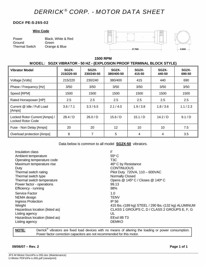
1500 RPM MODEL: SG2X VIBRATOR - 50 HZ - (EXPLOSION PROOF TERMINAL BLOCK STYLE)
Vibrator Model SG2X-215/220-50
SG2X-230/240-50
SG2X-380/400-50
SG2X- 415-50
SG2X- 440-50
SG2X- 690-50
Voltage [Volts] 215/220 230/240 380/400 415 440 690
Phase / Frequency [Hz] 3/50 3/50 3/50 3/50 3/50 3/50
Speed [RPM] 1500 1500 1500 1500 1500 1500
Rated Horsepower [HP] 2.5 2.5 2.5 2.5 2.5 2.5
Current @ Idle / Full Load [Amps]
3.6 / 7.1 3.3 / 6.5 2.1 / 4.0 1.9 / 3.8 1.8 / 3.6 1.1 / 2.3
Locked Rotor Current [Amps] / Locked Rotor Code
28.4 / D 26.0 / D 15.6 / D 15.1 / D 14.2 / D 9.1 / D
Fuse - Non Delay [Amps] 20 20 12 10 10 7.5
Overload protection [Amps] 8 7 5 4 4 3.5
Data below is common to all model SG2X-50 vibrators.
Insulation class F Ambient temperature 55º C Operating temperature code T3C Maximum temperature rise 46º C by Resistance Duty CONTINUOUS Thermal switch rating Pilot Duty 720VA, 110 – 600VAC Thermal switch type Normally Closed Thermal switch temperature Opens @ 145º C / Closes @ 140º C Power factor - operations 99.13 Efficiency - running 98% Service Factor 1.0 NEMA design TENV Ingress Protection IP 56 Weight 415 lbs.-(189 kg) STEEL / 290 lbs.-(132 kg) ALUMINUM Hazardous location (listed as) CLASS 1 GROUPS C, D / CLASS 2 GROUPS E, F, G Listing agency UL Hazardous location (listed as) EExd IIB T3 Listing agency DEMKO
NOTE: Derrick® vibrators are fixed load devices with no means of altering the loading or power consumption.
Power factor correction capacitors are not recommended for this motor. 09/06/07 – Rev. 2 Page 1 of 1
37.7500 9.5000

DERRICK® CORP. - MOTOR DATA SHEET
JFS M:\Motor Docs\Pe-s-266.doc (Maintenance) U:\Motor PDFs\Pe-s-266.pdf (view/print)
DOC# PE-S-266-01
Wire Code Power Black, White & Red Ground Green Thermal Switch Orange & Blue
1800 RPM
MODEL: SG2X VIBRATOR - 60 HZ - (EXPLOSION PROOF TERMINAL BLOCK STYLE)
Vibrator Model SG2X-215/220-60 SG2X-230/240-60 SGX2-380/400-60 SG2X-440-60 SG2X-460/480-60 SG2X-575/600-60
Voltage [Volts] 215/220 230/240 380/400 440 460/480 575/600
Phase / Frequency [Hz] 3/60 3/60 3/60 3/60 3/60 3/60
Speed [RPM] 1800 1800 1800 1800 1800 1800
Rated Horsepower [HP] 2.5 2.5 2.5 2.5 2.5 2.5
Current @ Idle / Full Load [Amps]
4.4 / 8.7 4.1 / 8.2 2.5 / 4.9 2.1 / 4.3 2.0 / 4.1 1.6 / 3.3
Locked Rotor Current [Amps] / Locked Rotor Code
34.9 / F 32.6 / F 19.6 / F 17.0 / F 16.3 / F 13 / F
Fuse - Non Delay [Amps]
25 25 15 12 12 10
Overload protection [Amps]
10 10 6 5 5 4
Data below is common to all model SG2X-60 vibrators.
Insulation class Ambient temperature Operating temperature code Maximum temperature rise Duty Thermal switch rating Thermal switch type Thermal switch temperature Power factor - operations Efficiency - running Service Factor NEMA design Ingress Protection Weight Hazardous location (listed as) Listing agency
Hazardous location (listed as) Listing agency
F 55ºC T3C 46º C by Resistance CONTINUOUS Pilot Duty 720VA, 110 – 600VAC Normally Closed Opens @ 145º C / Closes @ 140º C 99.13 98% 1.0 TENV IP 56 415 lbs.-(189 kg.) STEEL / 290 lbs.–(132 kg.) ALUMINUM CLASS 1 GROUPS C,D / CLASS 2 GROUPS E,F,G UL EExd IIB T3 DEMKO
NOTE: Derrick® vibrators are fixed load devices with no means of altering the loading or power consumption. Power factor correction capacitors are not recommended for this motor.
02/11/05 – Rev. 1 Page 1 of 1
37.7500 9.5000


![Title 46 46 MOTOR VEHICLES MOTOR VEHICLESleg.wa.gov/CodeReviser/RCWSelectedTitles/Documents/2017/...(2017 Ed.) [Title 46 RCW—page 1] Title 46 Title 46 46 MOTOR VEHICLES MOTOR VEHICLES](https://img.pdfslide.us/doc/110x75/5b2073857f8b9adb5d8b48fe/title-46-46-motor-vehicles-motor-2017-ed-title-46-rcwpage-1-title-46-title.jpg)