Embed Size (px)
Citation preview

EEL 4924 Electrical Engineering Design
(Senior Design)
Final Design Report
25 April 2012
Project Title:
Multi-Function Pontoon
(MFP)
Team Members:
Name: Mikkel Gabbadon Name: Sheng-Po Fang
Project Abstract:
Our project consists of building a remote boat with various sensors and GPS navigation.
Temperature and distance will be the main sensors mounted on the boat. The information received from
the sensors will be transmitted to an LCD screen via Xbee. The LCD screen will be mounted on the
controller which sends information back to the main board—also Xbee. There will also be a GPS
module which will receive the GPS coordinates a manually take control of the steering of the boat to
make it travel to pre-programmed way-points; while simultaneously transmitted the location and
distance to waypoint information back to the laptop screen. The boat will be controlled remotely by our
personally designed motor controller. The controller will control one 3-phase motor that will allow the
boat to accelerate and a stepper motor which facilitates turning.

University of Florida EEL 4924—Spring 2012 25-Apr-12
Electrical & Computer Engineering
Page 2/13 Final Report: MFP
Table of Contents
Abstract………...............................................................................................................................1
Project Features/Objectives……………………………………..………...……………………3
Concept/Technology Selection..................................................................................................... 3
Project Architecture…………………………………………………………………………….7
Distribution of Labor.................................................................................................................... 10
Parts List…………....................................................................................................................... 10
Projected Timeline ........................................................................................................................ 11
Figures and Tables:
Figure 1: Final Boat Frame Design……………………………………………………..………3
Figure 2: Xbee…………………………………………….……….…………………….……….4
Figure 3: EM406-A ………..…………………………………………………………….………5
Figure 4: Basic MSP-430 processor………………………………………………….…………..6
Figure 5: Distance Sensor(XL Max-Sonar EZ2)…………………………………………………6
Figure 6: Project Flow-Chart…………………………………….……………………………….9
Figure 7: Motor Driver Schematic……………………………………………………………….11
Figure 8: Motor Driver Schematic……………………………………………………………….12
Figure 9: MSP430 PCB………………………………………………………………………….13
Table 1: Showing Parts List…………………………………………………….………………10
Table 2: Showing division of Labor…………………………………………………………….10

University of Florida EEL 4924—Spring 2012 25-Apr-12
Electrical & Computer Engineering
Page 3/13 Final Report: MFP
Project Features/Objectives:
The main objective of our project is to design a system test water quality
Remote controlled boat.
GPS navigation and display data
Distance sensors and collision detection
Display all sensor data on LCD and all GPS on monitor
Completely wireless communication
Technical Concepts/Technology Selection:
To make all of these features possible there are several key objectives that must be achieved.
Boat Frame Design
This is probably the most important step in project. The boat will have to be designed in such a
way to protect all of the electrical components from water and support the weight of the PCB, motors
and power source .We are going to buy the frame of the boat and then modify it. The main modifications
are the two floatation devices that will be added to both sides of the boat. This add-on is incredibly
important because not only does it decrease the like-hood of the boat sinking—by increasing the
buoyancy, the boat will be able to support more weight; especially because some of the components—
motors, battery will be heavy.
University of Florida EEL 4924—Spring 2012 25-Apr-12
Electrical & Computer Engineering
Page 4/13 Final Report: MFP
Figure 1: Final Boat Frame Design
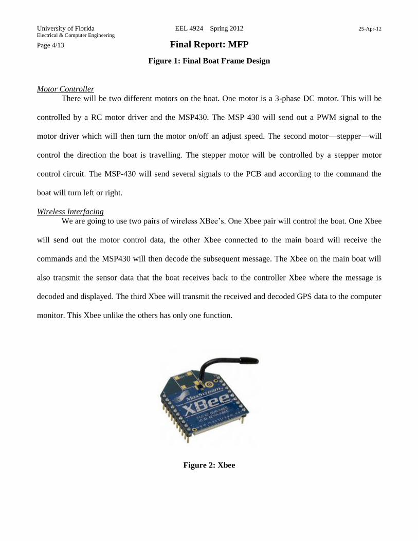
Motor Controller
There will be two different motors on the boat. One motor is a 3-phase DC motor. This will be
controlled by a RC motor driver and the MSP430. The MSP 430 will send out a PWM signal to the
motor driver which will then turn the motor on/off an adjust speed. The second motor—stepper—will
control the direction the boat is travelling. The stepper motor will be controlled by a stepper motor
control circuit. The MSP-430 will send several signals to the PCB and according to the command the
boat will turn left or right.
Wireless Interfacing
We are going to use two pairs of wireless XBee’s. One Xbee pair will control the boat. One Xbee
will send out the motor control data, the other Xbee connected to the main board will receive the
commands and the MSP430 will then decode the subsequent message. The Xbee on the main boat will
also transmit the sensor data that the boat receives back to the controller Xbee where the message is
decoded and displayed. The third Xbee will transmit the received and decoded GPS data to the computer
monitor. This Xbee unlike the others has only one function.
Figure 2: Xbee

University of Florida EEL 4924—Spring 2012 25-Apr-12
Electrical & Computer Engineering
Page 5/13 Final Report: MFP
GPS
We will be using an EM-406A GPS to receive GPS data. The GPS will be connected to a RX pin
on the microprocessor UART. The information received by the GPS-microp will then be decoded into a
buffer where the location can be stored so that further processes can happen.
Figure 3: EM-406A
Information Display
We will be using a 2 line LCD screen to display the sensor data received. The information will
be received via Xbee, decoded by the microprocessor and then displayed on the LCD screen. The GPS
positional data will be decoded by the microprocessor on the main board and then displayed on the
computer motor.
Microprocessor
We choose an MSP-430 with 64 pins to all of the operations. Specifically, we chose the MSP-
430F2619 because each 64-pin MSP-430 had two UART modules. The UART modules are especially
important because the only way for the Xbee’s and the GPS to communicate with the MSP-430’s is via
UART.

University of Florida EEL 4924—Spring 2012 25-Apr-12
Electrical & Computer Engineering
Page 6/13 Final Report: MFP
Figure 4: Basic MSP-430 processor
Sensors
The sensors account for the main analog component of this experiment. We are using two main
sensors for our project—temperature, distance/depth and PH sensors. The temperature sensor will be
placed on the base on the boat directly into the water. The temperature sensor will be able to measure
water temperature. The distance sensor will be placed on top of the boat facing outwards. The distance
will be used as an object detection device.
Figure 5: Distance Sensor( XL-Maxsonar EZ2)

University of Florida EEL 4924—Spring 2012 25-Apr-12
Electrical & Computer Engineering
Page 7/13 Final Report: MFP
Miscellaneous
There are also costs that will be added to the project apart from the main components. Overall the boat
should cost around $50.
Enclosure: We need two enclosures. One for the controller device and one to protect the
circuitry on the main board
Fans: We need 2 fan blades to attach to the DC motor component.
Water Proofing : Expoxy will be used to make the sensors water-proof and still usable
Power-Source: We need a 7.4v lipo battery to power all the various motors on the main board.
Also, a 9V battery for the remote controller.
Circuitry: We will need a lot of basic circuit components. Capacitors, MOS, resistors etc.
Project Architecture
The design of the boat was split into several modules:
1. Sensors
Both sensors on the boat were connected to the ADC of the MSP430F2619. The sensor data was
sampled using the ADC sampling timer. The ADC data was then converted from voltage data into
useable data and then stored in a buffer.
2. Xbee Communication
There were three Xbee’s and each Xbee performed a completely different function:
Xbee Controller—This Xbee performed two functions. It was connected to the MSP on the
controller via the UART. When the user presses a button on the controller the Xbee will
transmit a Byte of data containing all of the switch data. This Xbee will also receive data

University of Florida EEL 4924—Spring 2012 25-Apr-12
Electrical & Computer Engineering
Page 8/13 Final Report: MFP
from the Xbee Boat. While sending data, the Xbee will also receive strings of sensor data for
the MSP-430 to decode.
Xbee Boat—This Xbee also performs two functions. It receives controller data from the Xbee
Controller for the MSP430 to decode. It also transmits the string of sensor data to the
controller Xbee.
Xbee GPS—This Xbee transmits the decoded GPS data to another Xbee connected to the
computer. This Xbee data is then displayed on the X-CTU program.
3. GPS control
The GPS is connected to the MSP430 via the UART. The GPS receives satellite data and transmits
them to the MSP-430. The MSP430 then decodes the NMEA GPS data and stores the location in
several buffers. When the boat is switched to GPS mode the boat will drive to a stored way-point
and return to the first point that the GPS recorded.

University of Florida EEL 4924—Spring 2012 25-Apr-12
Electrical & Computer Engineering
Page 9/13 Final Report: MFP
Figure 6: Project Flow-Chart
University of Florida EEL 4924—Spring 2012 25-Apr-12
Electrical & Computer Engineering
Page 10/13 Final Report: MFP
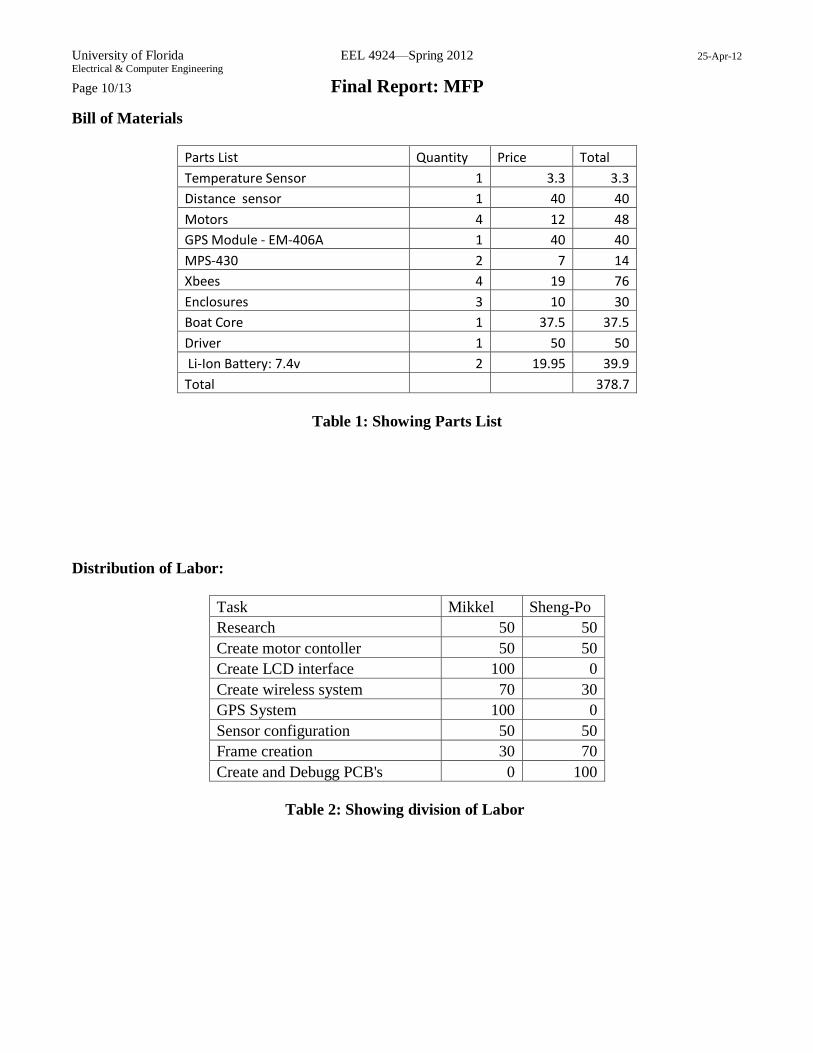
Bill of Materials
Parts List Quantity Price Total
Temperature Sensor 1 3.3 3.3
Distance sensor 1 40 40
Motors 4 12 48
GPS Module - EM-406A 1 40 40
MPS-430 2 7 14
Xbees 4 19 76
Enclosures 3 10 30
Boat Core 1 37.5 37.5
Driver 1 50 50
Li-Ion Battery: 7.4v 2 19.95 39.9
Total
378.7
Table 1: Showing Parts List
Distribution of Labor:
Task Mikkel Sheng-Po
Research 50 50
Create motor contoller 50 50
Create LCD interface 100 0
Create wireless system 70 30
GPS System 100 0
Sensor configuration 50 50
Frame creation 30 70
Create and Debugg PCB's 0 100
Table 2: Showing division of Labor

University of Florida EEL 4924—Spring 2012 25-Apr-12
Electrical & Computer Engineering
Page 11/13 Final Report: MFP
Appendices
Figure 7: Motor Driver Schematic

University of Florida EEL 4924—Spring 2012 25-Apr-12
Electrical & Computer Engineering
Page 12/13 Final Report: MFP
Figure 8: Motor Driver PCB

University of Florida EEL 4924—Spring 2012 25-Apr-12
Electrical & Computer Engineering
Page 13/13 Final Report: MFP
Figure 9:MSP430 PCB