Embed Size (px)
Citation preview
http://repository.osakafu-u.ac.jp/dspace/
Title Material Behavior in Grinding with Single Modified Tool
Author(s) Kita, Yoshihiro; Ido, Mamoru
Editor(s)
CitationBulletin of University of Osaka Prefecture. Series A, Engineering and nat
ural sciences. 1973, 21(2), p.175-186
Issue Date 1973-03-31
URL http://hdl.handle.net/10466/8253
Rights
・175
Material Behavior in Grinding with Single
Modified Tool
Yoshihiro KiTA* and Mamoru IDo*
(Reseived November 15, 1972)
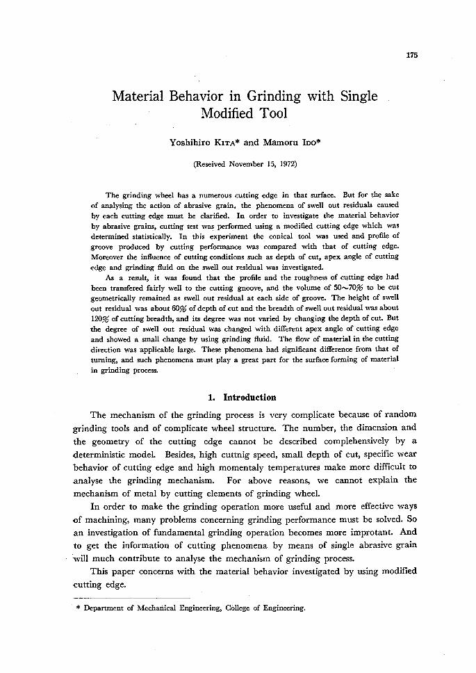
The grinding wheel has a numerous cutting edge in that surface. But for the sake
of analysing the action of abrasive grain. the phenomena of swell out residuals caused
by each cutting edge must be clarified. In order to investigate the materia! behavior
by abrasive grains, cutting test was perfbrmed using a modified cuttlng edge which was
deterrnined statistically. In this experiment the conical tool was used and profile of
groove produced by cutting perfbrmance was compared with that of cutting edge.
Mereover the infiuence of cutting conditions such as depth of cut, apex angle of cutting
edge and grinding fiuid on the swell out residual was investigated.
As a result, it was fbund that the profi!e and the roughness of cutting edge had
been transfered fairly well to the cutting gnoove, and the volume of 50.v70% to be cut
geometrica!ly remained as swell out residual at each side of groove. The height of swe!1
out residual was about 60% of depth of cut and the breadth of swell out residual was about
120% of cutting breadth, and its degree was not vaTied by changing the depth of cut・ But
the degree of swell out residua! was changed with different apex angle of cutting edge
and showed a smal! change by using grinding fluid. The flow of rnaterial in the cutting
direction was applicab!e large. These phenomena had significant difrerence from that of
turning, and such phenomena must play a great part for the surface forming of material
in grinding process.
1. Introduction
The mechanism of the grinding process is very complicate because of random
grinding tools and of complicate wheel structure. The number, the dimension and
the geometry of the cutting edge cannot be described complehensively by a
deterministic model. Besides, high cuttnig speed, small depth of cut, specific wear
behavior of cutting edge and high momentaly temperatures make more difeicult to
analyse the grinding mechanism. For above reasons, we cannot explain the
mechanism of metal by cutting elements of grinding wheel.
In order to make the grinding operation more usefu1 and more effective ways
of machining, many problems concerning grinding performance must be solved・ So
an investigation of fundamental grinding operation becomes more improtant. And
to get the information of cutting phenomena by means of single abrasive grain
・ will much contribute to analyse the mechanism of grinding process.
This paper concerns with the material behavior investigated by using modified
cutting edge.
* Department of Mechariical Engineering, Cbllege of Engineering.
276 Y. KrTA and M. IDo 2. Experimental Procedure
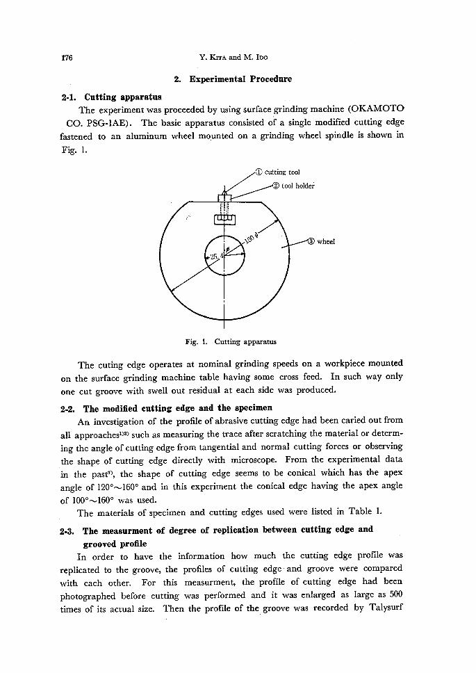
2-1. Cutting apparatus The experiment was proceeded by using surfa¢e grihding machine (OKAMOTO
CO. PSG-IAE). The basic apparatus consisted of a single modified cutting edge
fastened to an aluminum wheel mounted on a grinding wheel spindle is shown in
Fig. 1.
O cutting tool
f"
`i:
2s.4
@ tool holdef
li, ll
l
,
m
sss)lj
,
3 whbe1
Fig. 1. Cutting apparatus
The cuting edge operates at nominal grinding speeds on a workpiece mounted
on the surface grinding machine tab!e having some cross feed. In such way only
one cut groove with swell out residual at each side was produced.
2-2. The modified cutting edge and the specimen
An investigation of the profile of abrasive cutting edge had been caried out from
all approachesi)2) such as measuring the trace after scratching the material or determ-
ing the angle ofcutting edge from tangential and normal cutting forces or observing
the shape of cutting edge directly with microscope. From the experimental data
in the past3), the shape of cutting edge seems to be conical which has the apex
angle of 1200N1600 and in this experiment the conical edge having the apex angle
of 1000-v1600 was used: '
The materials of specimen and cutting edges used were listed in Table 1.
2-3. The measurrnent of degree of replication between cutting edge and
grooved profiIe
In order to have the information how much the.cutting edge prorne was
replicated to the groove, the profiles of cutting edge and groove were compared
with each other. For this measurment, the profile ofcutting edge had been
photographed before cutting was performed and it was enlarged as large as 500
times of its actual size. Then the profile of the groove was recorded by Talysurf

Mhterial Behavior in, Grinding with SVhgle Mbdijied 7lool
-.,. Table・ 1. Specimens and cutting tools
(a)' Msterials of Speeirnen
W7
Material.Heattreatmentannealed
intheVacuumHardness(Hv)
S15CS55CAI
Cu
gooec6omin.7goec6omin.
350℃30min.500℃30min.
102
,185
・32
44
(b) Cutting tgols
Shape Conical
Apexanglee 100"--1600
Cuttingtool
materiaIs
Diamond.
Cementeddarbide.
Highspeedsteel
Abrasivegrain2A
IV at the magnification as large as 500 times of its actual size in both horizontal
and vartical direction.
And also the roughness of the flank of the cutting edge and the groove were
measured by Talysurf IV and compared with each other.
2-4. The measurment of swell out residuals
The swell out residual at each side of the groove produced by cutting is
shown schematically in Fig. 2. To represent the extent of defbrmation, the height
and the breadth of swell out residual were measured from the profile, and fo11owing
two coethicients were denoted.
z y
y
x Xl
L
h
la
£ bu
.ha
e
02 x va 1 1 x-x
Fig. 2. Swell out residual produced by cutting
Hight coeMcient of swell out residual rh :
Breadth coethcient of swell out residual rb :
The profile of the groove was recorded at the
direction. To measure the profile at aceurately spaced
the groove, the specimen was set on the cross
dx
sectlon
and measured terms
rh = (h, + h,) 12d
rb == (bi + b2) !2be
center of groove in the cutting
section along the length of ,
table which could be moved,

178 Y. KiTA and M. IDoaccurately by the screw with dial indicator. By summing those all profiles, the
volume of swell out residuai can be caluculated and also the volume which is to
,be removed by the cutting edge geometrically can be obtained as following.
Now, we set the Z-coordinate along the length of groove and describe the
area of profile of groove as Wlx and the area of swell out tesidual as W>z. Then
VVI2-Il4iz represents the area of material removed in that section and denoted
(VVIx-I4,Za)IWIz to removal ratio and also %z/IJVIx to residual ratio. And describing
the distance between adjacent two sections as dZi ll2>adZ represents the volume of
swell out residual at that sections. So the total volume of swell out residual
around thLe groove is .:LL.i W2zdZ and total volume of the groove to be cutLis .>L:..],VVIzdZ
So that .Z.-,{ (Wlz- W>a) 1.Wlz} repre.sents the removal volume ratio and .Z.-, (VVLz/Wl.)
represents the rsidual volume ratio respectively. In this experiment dZ was taken
as 250pt and the relation between the length and the depth ofcut is listed intable 2.
' , Table 2. The relation between the depth of cut and the
!ength of groove
・ 3. Results and Discussion tt3-1. The degree of replication between cutting edge and groove profile.
To represent the degree of rep!ication, the angle of profile of cutting edge e
and the angle of groove e' were measured and compared with each other. Then
the ratio e'/e was caluculated and p!otted fbr the various depth of cut (d) in Fig.
3. Fig. 3 (a) shows the result for the materials Al, S15C, S55C taking the apex
angle of cutting edge as patameter. Fig. 3 (b) shows the effect of speed on the
1-degree of replication and Fig. 3 (c) is the similar exprimental result when the
diamond cutting edge is used. According to these results, we can realize easily
that the profile of cufting edge is replicated fairly well to the groove.
Then the replication of surface roughness of cutting edge on the groove was
investigated and its results are shown in Table 3. Table 3 (a) is the results tested
by various cutting tool materials such as Cemented carbide, High speed steel and
Abrasive grain (2A). And Table 3 (b) is the results examined in various cutting
speeds such as 1700, 600, 400 and 240 m/min.
From these results it becomes clear that the surface roughness of cut groove is
the same order as the roughness of cutting edge in perpendicular to the cutting
direction but it is very small in the cutting direction. And there is a tendency
that the surface roughness is smaller for the hard material than the softer one.
Thedepthofcut(d)pt 10 20 30 40 50
Thelengthofgroove(L)mm 2,5 3.6 4.4 5.0 5.6

Mlriterinl Behavior in orinding wih'ic sttrgle A`fodZtied 7bel 'tro
1.2
Ri.ott Lct' " ' '
O. 8 o
1. 2
as'is 10
O. 8 o 1,. 2
cts.
NLO " O.8 o
'
S15C
tttt ttt .ttt-tt - J'.. ;tt.t.. t.t. tt. /ttt .t
10 2Q・ id(pt).
30
r・-1
S55C
..}
tt-
'
10 20d(pt)
30
(a) Thg, etfqct g.f .. materials tQ'.be cut. ..
' V-t1700mhnitu
40 cemented carbide tool
' o esi 160q・ '
e ez l4oo ・・ o B,Ei li20" . ,)
4o O e= looo .
Al
10 20d(pt)-
30 40
1. 2
"is'1. 0
o. 8o
ct, 1・2
tsqb 1.0
O.8 o
1. ・2
"N1.0" O. 8
1.2cb 'li.o
' O.8 o
=・- .ttt
S15C'.t
'''
'
10 20・d(pt)
・ 30 40
'
S55C
10 20{ ・ ' 30 ttt t t.ttd(pt)・ 1.
'40
It tt
sls6
o1020d(.).39 40'5Q'
tt
・S55C
t
(b) The:e.ffegt.p.f,--.,
cntting speed.:' ...'
' o V = 1700mimini・ .
e .'V .- 600 m/inin.
V =,oo. Omhnin. ..
o V = 200 mimin.
-/.' l ",, l ' ・・ :/'Cc5 The effect of
cutting edge matetial
, V= 17POmhnin.
diamond too1 '
O e; 16oe e e=.14oe o ei= IQoe
10 20 30 4Q 510 1. d(") .. ・i Fig. 3. degree of replication between cuttihg edge and groove profile . ' /-
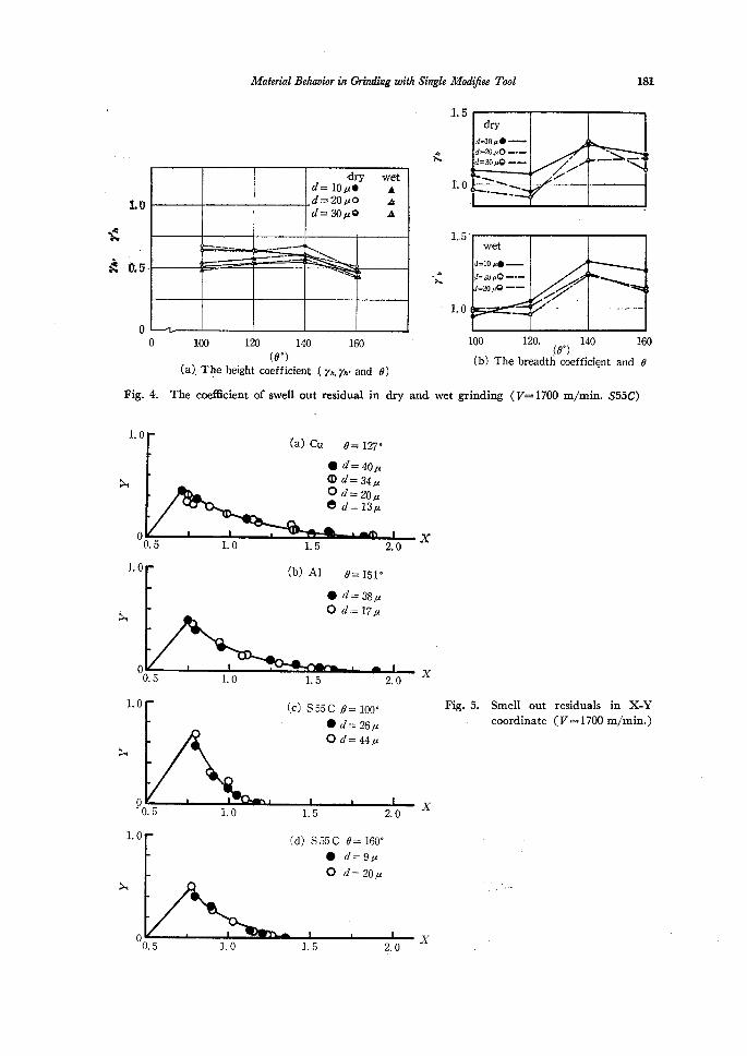
3-2. The swell out residuals
The coeficient of swell out residual was caluculated and listed in Table 4,andi
the results are shown in Fig. 4. rh, rb and r'h, r'b are the coethcients inithe
'conditions of dry and wet grinding.rcspectively, This rcs.ult indicate that the s .eff;ect of depth of cut on the gpethciehi・' i=s 'a little. . ' ''' ・
To investigate the profile. o/f swell out residual more detail similar experiments
were carried out for different ・materials 'in various' depthes of cut.
For normarizing the size of swell out residual the profile was expressed in the
two-dimensonal standerd coordinate X, Y:that is' '
X =xlb.e where x is abscissa represents the distance from the center of groove
and b, is the breadth of cutting edge at the heightd '・ Y=orld where y is ordinate represents the height of swell out residual and d
is the depth of cut. ・

-1eo
(a) The effec't
Y; K!zz ptrd- M. Ibo.
Table 3. The replication of surface roughness
of cutting .mater'ial
Surfaeercnlglmessof
grooveS15CRmaxIt
Surfaceroughnessof.
grooveS55CRmaxFtCuttingedge
e=-14oo
Sur.face
roghness..Qf
cuttingedge,
(Rmax)g
Parallpltocuttmgdirection'
Rectangular.tocuttmgdirection Parallglto
cuttmgdirection
Rectangular.tocuttmg
direction
.Cemented
caride(G2)
Highspeedsteel
Abrasivegrain(2A)
O.34
O.45
O.38
O.08
O.05
O.10
O.30
O.52
O.40
O.05
e.so
O.07
O.20
O.47
O.30
(6) The effect of cutt'm' g speed
Surfaceroughnessofgroove
CuttingedgeCuttingspeed
Vmlm'inParallelto
cuttingdirectionRectangularto
cuttingdirectiontt
Abrasive
grain
e-14oe
RmaxO.38pt
1700
600
400
240
O.07
O.07
O.09
O.10
O.30
O.31
O.32・
O.42
Table 4. The height coeMcient in dry ('rh) and wet (rh') condition
'
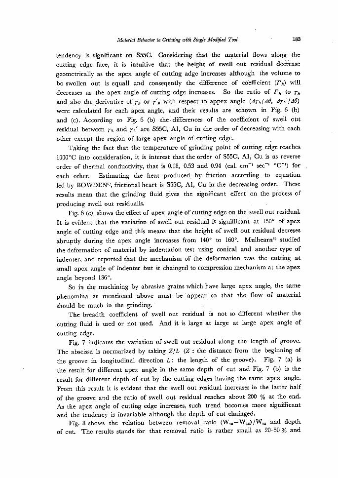
Fig. 5 shows the swell out residuals represnted using X-Y coordinate, and it is
evident that the profile of swell out resklual produced by the same cutting edge
are the same although the depth of cut is diflbrent. But as shown in Fig. 4 the
・profile of swell out residual is rnore influenced by the cutting edge having larger
apex angle. And at the region of small apex angle it is much influenced by the
'S55C Al Cu
eo dpt 7h 7fi 7h '7fi .7h 7h'
10 O.65 O.49 O.61 O.53 O.56 O.51
100 20 O.68 O.51 O.65 O.55 O.61 O.53
30 O.64・ O.54 O.60 O.53 O.61 e.57
10 O.64 O.'54 O.67 O.60 O.58 O.54
120 20 O.64 O.54 O.59 O.50 ・O.64 O.62
30 O.65 O.57 O.60 O.53 O`63 O.60'
10 O.60 O.58 O.57 O.51 O.39 O.35.
140 20O.60l
O.55 O.61 O.54 O.39 O.3430 O.67 O.61 O.64 O.55 O.42 O.39
'
10 O.47 O.43 O.45 O.42 O.48 O.46
16e ee O.52 O.49 o." O.43 O.37 O.36''
30 O.49 O.44 O.'35 O.35. O.31 O.30
-aj
Nft
1,O
'ct5・
o o
Fig. 4.
1. 0
N
o
1.0
N
o
1.0
N
p
zo
N
o
dry1vetd=lopteAd=120AO.tsd=so"oA
/ -L-.- -"----"-1-'~"-'
' NN
(a
The
Mbten'al Bchaviar in (]rimling with Si,rgle MbdViee Ibel 18S
l.5
g
1.5 wet
d=le"e. -£ d;.co:.O-.in: .f,7fff X
・ 1.0
). Tlje height coefficient, ・< rh, ?th・ and e) '
coeMcient of swell out residual in -dry and wet grinding (V== 1700 m/min. S55C)
{a.) Cu e= 127e
e d= 4o pt O d= 34# Od=20pt e d== 13"
x LO l.5 2.0 (b) Al e= lslo
e d-- 3s pt O d= 17pt
dry
d=le#e-d;20.#O-.-=30re---
"Nt.1./
>s"!N-`NNe・'
Sliib`N.-.--'
O. 5
O. 5 1.Q L5
Cc) S55C o = 1,ooe
e d= 26 pt
Od=44"
2. 0 X
X
Fig.5. Smell out coordinate
residuals in X-Y(V ma 1700 m/min.)
O. 5 1.0 1.5
(d) S55C
e o
e== 16oe
d== 9"
d== 20"
2. 0
X
't
O.5 1.0 l.5 Z・ o

'182 ・ Y. KrrA and M. IDogrinding fluid. In,Fig. 4 the 'coeMcient of rn decrease progrssively as apex angle
increase from 100e to 1400 and it decrease abruptly at the apex angle between
1400-1600 in dry grinding. On"the other had, in wet grinding tb.e coeMcient
increase as.the apex angle between 1200"vl400.but it chainges the trend and
g:2geawSeerghaenaaPiyesXeda:sglfai?oewtX.negeP i400'yi600・ inorder to make.ciear this tenq,.p, cy
f"s Fig. 6 (a) show the differerce of the coeMcient of swell out residual (rh>"'
between dry and wet grinding on Al, Cu, S55C and the relation among rhi.pa. e.;
(apex angle of cutting edge) are represented. We can recognize that the diffbrence
of coeMcient (rh) increases as apex angle of cutting edge becomes small and this
tt ttt
'
O.2
£O.1
o 100 1eo ・140 1oo (t7)e (a) The relation hetween ili and e O. 3
O. 2 s' x・ R:
O. 1
o, '100 120 140 1oo <e)o (b) The relation hetween.I'Ulva and e O.2
R.
SO.1 ' N lt . "
NstO , l /1・
--o.i 1 110 (e)130 150 r (c) The ratid dn,fdad7i:!de and e i,
Fig. 6. The effect of fluid on the swell out residual (V=17oo mlmin.)
Il/
OS55C"AlACU
・I・
-/- L--- --.N <
"A- N
Mif20
--x- .t. .N
30
20 tsk"X
--10
;.--. -- -L--
'. 10
't-.
ts
d=10p20"30ptS55CQOO
AIaoCu・A・A
-×'x. '-
- .
-..---
N.N"-.
-..-...
'
S55Cdrywetd=lopteAd=20ptOLd==30pt.OA
,
tttt
v-t'/t
'?r==-t-bec".
Mdten'al Behavinr in Grihcting with Single MbdZtied 7'bol 183
tendency. is significant on S55C. Considering that the m4terial flows along the
cutting edge face, it is intuitive that the height of swell out resldual decrease
geometrically as the apex angle of cutting adge increases although the volume to
be swollen out is equall and conseqently the 'diflbrence of cdeM'cient (rh) will
decreases as the apex angle of cutting edge increases. So the ratio of rh to rh
and also the derivative of rh or r'h with respect to appex angle (drh/Ae, ztrh'IAe)
were calculated fbr each apex angle, and their results are schown in Fig. 6 (b)
and (c). According to Fig. 6 (b) theldiffbrences of the coeMcient of swell oUt
residual between rh and rh' are S55C, Al, Cu in the order of decreasing with each
other except the region of large apex angle of cutting edge. . Taking the fact that the terr}Per,ature of grinding point of cutting edge reaches
10000C into consideration, it is int6rest that the order of S55C, Al, Cu is as reverse
order of thermal conductivity, that is O.18, O.53 and O.94 (cal. cm"t sec"" OC"t) for
eagh other. Estimating the heat produced by friction according to equation
led by BOWDEN5), frictional heart is S55C, Al, Cu in the decreasing order. These
results mean that the grinding fluid give's the significant effect on the process of
producing swell out residualls. . , Fig. 6 (c) shows the efuct of apex angle of cutting edge on the swel! out residual.
It is evident that the variation of swell out residual is signiMcant at 1500 of apex
angle of cutting edge and this means that the height of swell out "residual decreses
abruptly during the apex angle increases from 140e to 1600. Mulhearn6) studied
the deformation of material by indentation test using conical and another type of
indenter, and reported that the mechanism of the deformation was the cutting at
small apex angle of indenter but it chainged to compression mechanism at the apex
angle beyond 1360.
So in the machining by abrasive grains which have large apex angle, the same
phenomina as mentioned above must be'appear so that the flow of materia!
should be much in the grinding.' ' . '' The breadth coeMcient of swell out residual is not so diflbrent whether the
cutting fluid is used or not used. And it is large at large at large apex angle of
cutting edge.
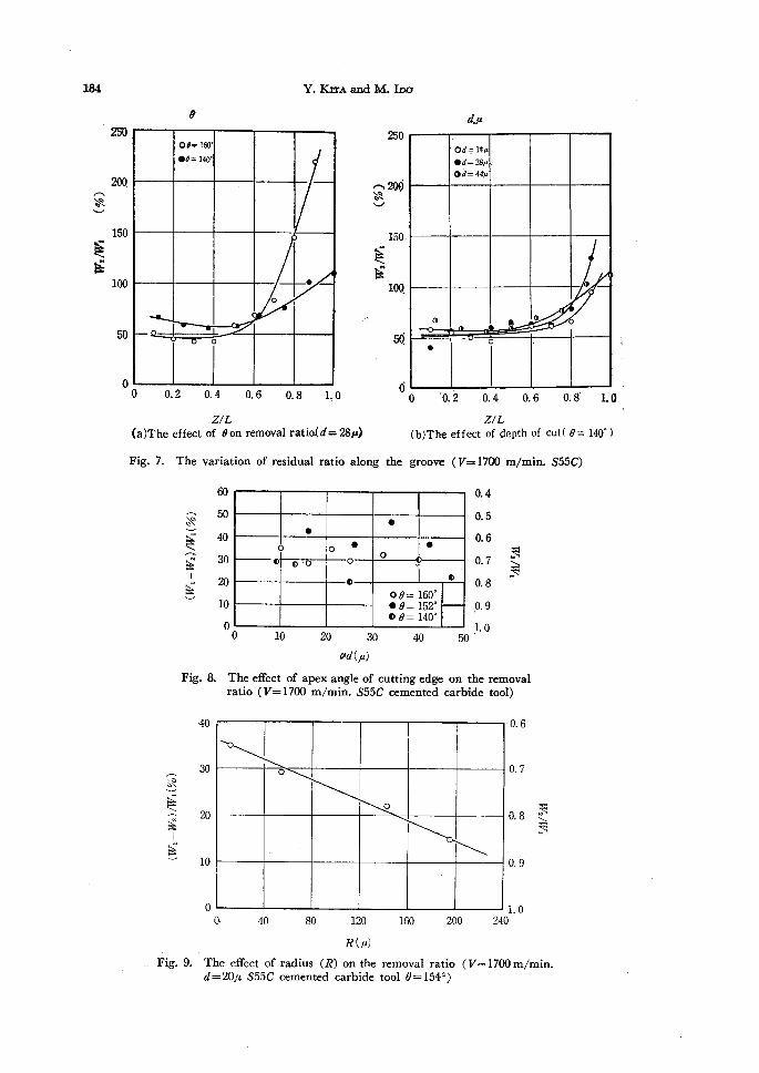
Fig. 7 indicates the variation of swell out residua! along the length of groove.
The abscissa is normarized by taking Z/L (Z:the distance from the beginning of
the groove in longitudinal direction L: the length of the groove). Fig. 7 (a) is
the result fbr diflbrent apex angle in the same depth of cut and Fig. 7 (b) is the
result for different depth of cut by the cutting edges having the same apex angle.
From this result it is evident that the swell out residual increases in the latter half
of the groove and the ratio of sweli out residual reaches about 200 % at the end.
As the apex angle of cutting edge increases, such trend becomes more signiMcant
and the tendency is invariable although the depth of cut chainged.
Fig. 8 shows the relation between remova} ratio (Wiz-W2a)/Wiz and depthof cut. The results stands fbr that removal ratio is rather small as 20-50 % and
184
A"v
Eg
am
20Q
150
1oo
50
o
e
Y. Ki rA and M. Ico
oe=1oo'
e-e=14ee
.
o
o
aso
,A 2QeX."N
v
EE
O O.2 O.4 O.6 O.8 1.0 ZIL(a)The effect of e・on removal ratia(d='ggA)
Fig. 7. The variation of residual ratio along
150・
1co
5Q
d
the
4pt
Od=14"'
ed=28#'Od=44B,
o e
.'
e 'e. 2' or4 o.6
ZIL(b)The effect of depth of
groove (V=17oo mlmin.
O. 8'
cut( e =
S55C)
1.0
14o")
,
'
a=N>sL
g
Fig. 8.
60
50
40
30
ee
10
o
ee
o oe e
o o'
oQ
otto
o
oe==16ooee=ls2"oe=14oe
o
The effect
ratio (V
10 20 30 40 crd(.pt)
of apex angle of cutting edge
=1700 mlmin. S55C cemented
50
O. 4
e. s
O. 6
O. 7
O. 8
O. 9
1. 0
gek
on the removalcarbide tool)
AYN>sL
E
.. Fig.
・40
so
20
10
o
O・ 40 80 120 R(pt)
9. The eflbct of radius (R) on the
d==20pt S55C cemented carbide
o
o
16e 200
removal ratio (V==tool e==ls4o)
240
O. 6
O. 7
O.8 S
g
O. 9
LO
1 7oo m/min.

Mbterial Behavior in Gbuinding evith Siagle MbdZtied 7lool 185
almost of material remains as swell out resldual at each side of the groove The
effect of radious of cutting cdge (R) on the removal ratko was investigated and its
result is shown in Fig. 9. In the limit ef this experiment (d=20st, R==10"v200pt),
the removal ratio decreases as the radious of cutting edge increases. In another
words swell out residual becomes large by daN cutting edges, and this means ifthe
radious of cutting edge reaches characteristic value by the cause of wear, all mate-
rial to be cut remains as sw,ell out residual. In the agtual grinding process the
geastitdeunaeidmduUsiti bCeUtitoi?.g edges piay a great part, and consc¢quentiy the swep out
' ' Fig. 10 represents the effect of inteerencg angle (a) on the removal ratio andthis result indicates that the removal ratio is larger when cuttihg is performed at
smaller interference angle and it is not so infiuenced by the depth of cut.
60 O.4 A "60 O.5 = it・ 40 O.6 S・30 O.7S N- 2o o.s v
-10 O.9 O LO 'O 10 '20 ,30 40 50 d(p)
Fig. 10. The effect of interference angle on the removal ratio (V== !700 mlmin. S55C cemented cabride tool e= 1540)
To promoting grindining machinings, the most effective condition must be
constructed and this is a important subject for a future study. This experiment
will be usefu1 in solving iater problems.
4. Conclusion
From this basic expreiment, fbllowings were made clear
l. The profile and the roughness of cutting edge are replicated fairly wel! to
the cut groove.
2. The swell out residuals are influenced by using grinding fluid significuntly at
the apex angle of cutting edge between 1000tvl400. But at the larger apex angle
of cutting edge beyond 1400, the deformation by compressign mechanism play a
great role in the process of producing swell out residuals.
3. The depth of cut has not significant aflbct on the swe!1 out residuals. The
height coethcients of swell out residual are O.4-vO.7 and the breadth coeMcients are
1.0N2.0 in the limit of this experiment on Al, Cu and S55C.
4. The removal ratio is 20Ay50% and almost of material remains as swell out
residual at each side of the groove. And its ratio is afl}ected by the radious of
o o
o
o
o.
ge
o oole-e
oI
oe
ea=3eOa=13oOa=230

・186 Y. KiTA and M. IDo
cutting edge and the interference angle.
5. In the cutting by abrasive grain, the material fiow into cutting direction is
signficant and swell out residual becomes large at the lattcr half of the groove.
Referenees
1) K. Okamura, Jour. Soc, Prec. Mech. Japan, 27, 333 (1961).
2) A. Kobayashi, Jour. Soa Prec. Mech. Japan, 24, 95 (1950).
3) M.' Matui, Jcrur. Sci. Mach. Japan, 2eq 1611 (l971).
4) J. O. Oatwater and M. C. Show, Tran. ASME, U, 73 (1952).5) E P. Bowden and O. Tabor, The friction and lubrication of Solids, p. 31 Oxfbrd (1954).
6) T. O. Mulhearn, Jour. Mech. Pech. Phys. Solid, 7, 85 (1959).