Embed Size (px)
Citation preview

1
Paper IBC 17-89
34th International Bridge Conference
Gaylord National Resort, National Harbor, MD
June 5-8, 2017
Title: Low-Cost Scour Preventing
Fairings for Bridges
ROGER L. SIMPSON, Ph.D., P.E., M.ASCE corresponding author
Email: [email protected]
Phone: (540)-961-3005
FAX: 866-223-8673
GWIBO BYUN, Ph.D.
Email: [email protected]
Phone: (540)-553-5139
FAX: 866-223-8673
Applied University Research, Inc.
605 Preston Avenue
Blacksburg, VA 24060-4618
KEYWORDS: Bridge scour prevention; scour-vortex prevention;
bridge piers; abutments; vortex generators
2
Abstract
Cost-effective optimized robust scour preventing three-
dimensional convex-concave hydrodynamic fairings (scAURTM) with
attached counter-scour vortex generators (VorGAURTM) have been
designed, developed, extensively tested at model and full scale
under NCHRP-IDEA sponsorship, and are now available for
practical use for bridge piers and abutments. Their particular
shape prevents creation of scouring vortices that cause the
local scour problem for any river level, speed, and angles of
attack up to 20 degrees (45 degrees with a “dog-leg). Many
advantages are discussed.
Introduction- Background of Bridge Pier and Abutment Scour
Removal of river bed substrate around bridge pier and abutment
footings, also known as scour, presents a significant cost and
risk in the maintenance of many bridges throughout the world and
is one of the most common causes of highway bridge failures (1).
In a recent work (2), it is estimated that over 70% of US
bridges were not designed for scour prevention and that peak
flows during floods cause most scour and failures over a short
period of time. It has been estimated that 60% of all bridge
failures result from scour and other hydraulic-related causes
(3). This has motivated research on the causes of scour at
bridge piers and abutments (4) and led bridge engineers to
develop numerous countermeasures that attempt to reduce the risk
of catastrophe. Unfortunately, all previously used
countermeasures are temporary responses that require many
recurring costs and do not prevent the formation of scouring
vortices, which is the root cause of the local scour (5,6).
Consequently, sediment such as sand and rocks around the
foundations of bridge abutments and piers is loosened and
3
carried away by the flow during floods, which may compromise the
integrity of the structure. Even designing bridge piers or
abutments with the expectation of some scour is highly
uncertain, since a recently released study (5) showed huge
uncertainties in scour data from hundreds of experiments. None
of the conservative current bridge pier and abutment footing or
foundation designs prevent scouring vortices, which are created
when the flow interacts with underwater structures, so the
probability of scour during high water or floods is present in
all previous designs.
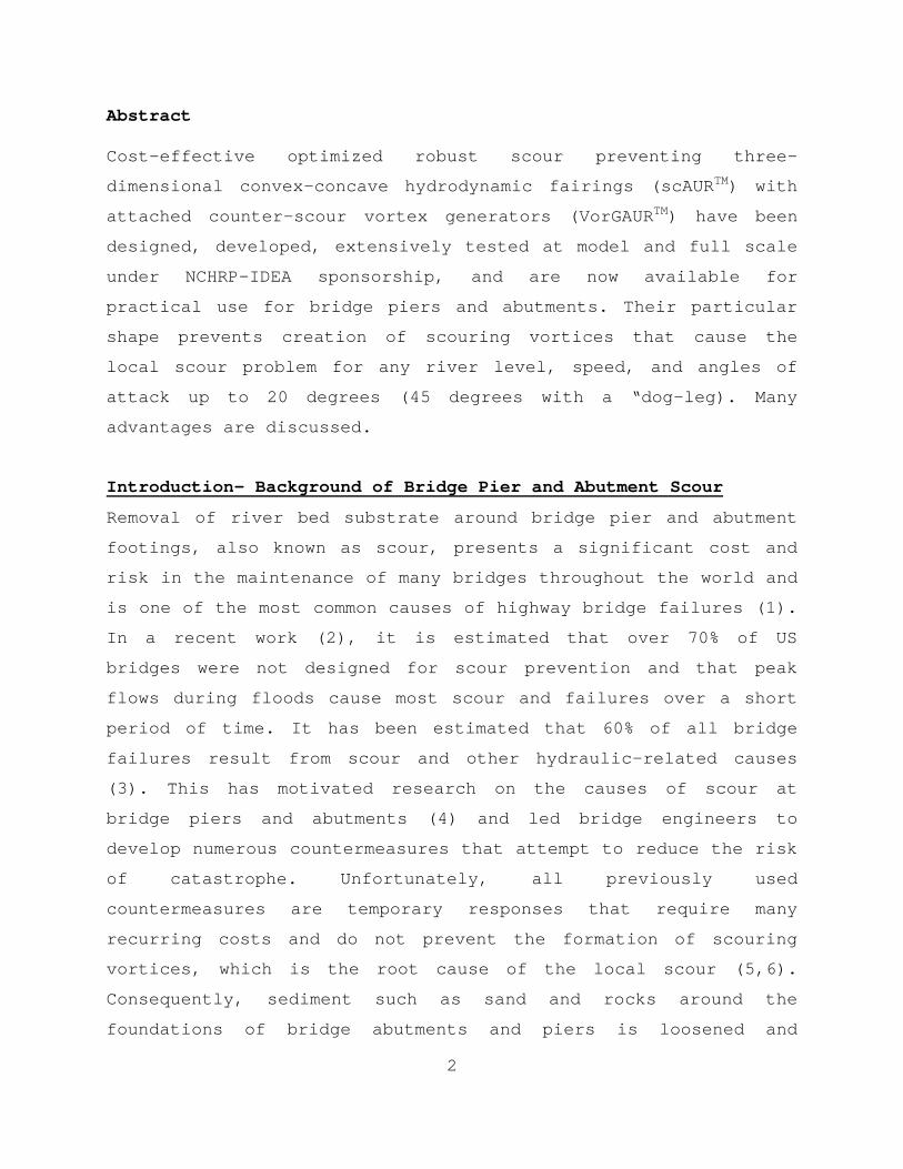
The bridge foundations in a water current, such as piers and
abutments, change the local hydraulics drastically because of
the appearance of large-scale unsteadiness and shedding of
coherent vortices, such as horseshoe vortices. Figure 1a is a
sketch of the horseshoe vortex formed around the base of a pier
by a separating boundary layer. The horseshoe vortex produces
high bed shear stress, triggers the onset of sediment scour, and
forms a scour hole. (See www.noscour.com.)
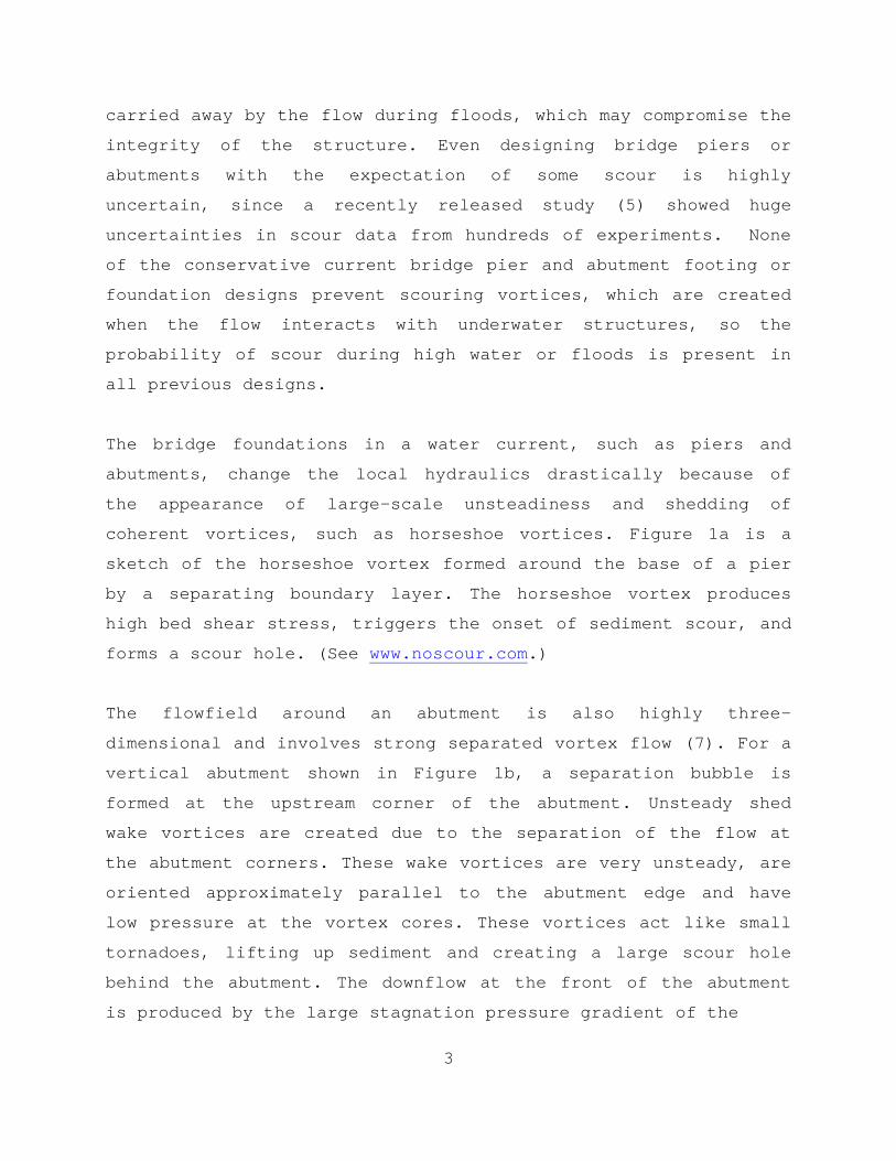
The flowfield around an abutment is also highly three-
dimensional and involves strong separated vortex flow (7). For a
vertical abutment shown in Figure 1b, a separation bubble is
formed at the upstream corner of the abutment. Unsteady shed
wake vortices are created due to the separation of the flow at
the abutment corners. These wake vortices are very unsteady, are
oriented approximately parallel to the abutment edge and have
low pressure at the vortex cores. These vortices act like small
tornadoes, lifting up sediment and creating a large scour hole
behind the abutment. The downflow at the front of the abutment
is produced by the large stagnation pressure gradient of the
4
Figure 1a. The formation of a horseshoe vortex around the bottom
of a bridge pier with no scouring-vortex prevention.
Figure 1b. . The formation of a scouring vortices around a
vertical abutment with no scouring-vortex prevention.
approaching flow. The down flow rolls up and forms the primary
5
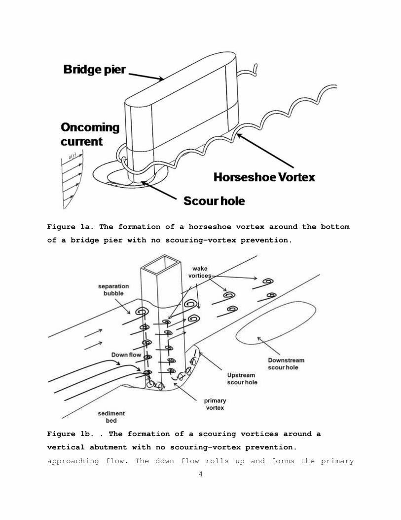
vortex, which is similar to the formation of the horseshoe
vortex around a single bridge pier.
Figure 1c. Flow structure around the spill-through abutment with
no scouring vortex protection.
For the spill-through abutment with no scour protection, the
flow is accelerated around the contraction and
separated downstream of the contraction leading edge as shown in
Figure 1c. There is a free surface level difference before and
after the contraction leading edge due to the free surface
vortex formation. The spill-though abutment has the scour hole
at the downstream of the model with the similar order of depth
of the vertical square corner wall due to the free surface
vortex generated at the leading edge of the contraction.
It should be noted that rip rap countermeasures are not
acceptable design elements for new bridges (1). To avoid
liability risk to engineers and bridge owners, new bridges must
5
vortex, which is similar to the formation of the horseshoe
vortex around a single bridge pier.
Figure 1c. Flow structure around the spill-through abutment with
no scouring vortex protection.
For the spill-through abutment with no scour protection, the
flow is accelerated around the contraction and
separated downstream of the contraction leading edge as shown in
Figure 1c. There is a free surface level difference before and
after the contraction leading edge due to the free surface
vortex formation. The spill-though abutment has the scour hole
at the downstream of the model with the similar order of depth
of the vertical square corner wall due to the free surface
vortex generated at the leading edge of the contraction.
It should be noted that rip rap countermeasures are not
acceptable design elements for new bridges (1). To avoid
liability risk to engineers and bridge owners, new bridges must
6
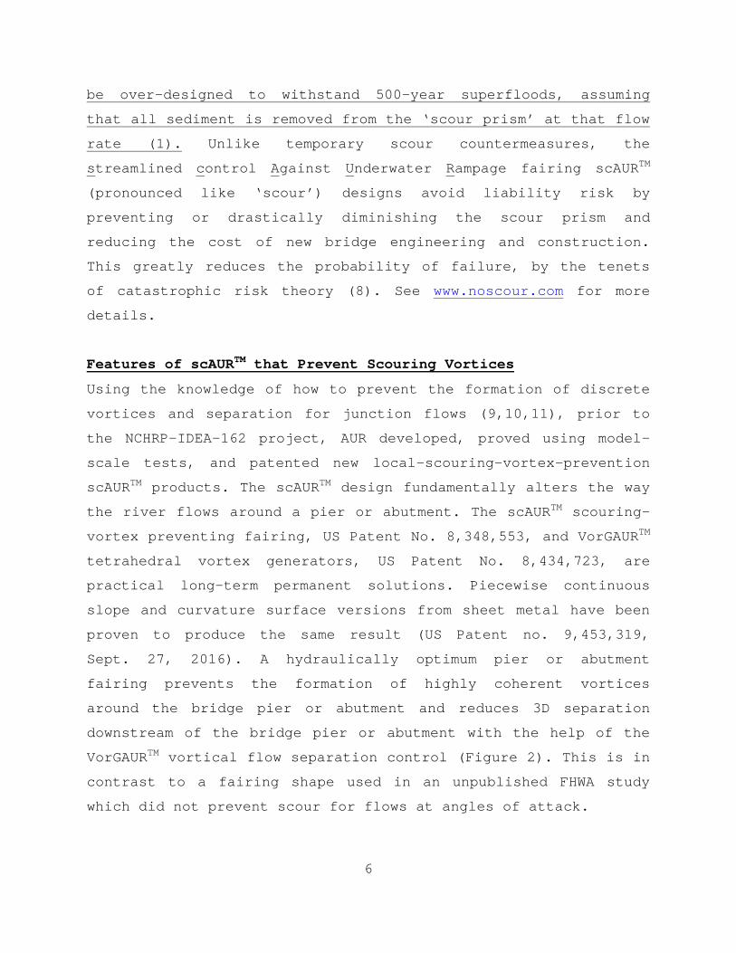
be over-designed to withstand 500-year superfloods, assuming
that all sediment is removed from the ‘scour prism’ at that flowrate (1). Unlike temporary scour countermeasures, the
streamlined control Against Underwater Rampage fairing scAURTM
(pronounced like ‘scour’) designs avoid liability risk by
preventing or drastically diminishing the scour prism and
reducing the cost of new bridge engineering and construction.
This greatly reduces the probability of failure, by the tenets
of catastrophic risk theory (8). See www.noscour.com for more
details.
Features of scAURTM that Prevent Scouring Vortices
Using the knowledge of how to prevent the formation of discrete
vortices and separation for junction flows (9,10,11), prior to
the NCHRP-IDEA-162 project, AUR developed, proved using model-
scale tests, and patented new local-scouring-vortex-prevention
scAURTM products. The scAURTM design fundamentally alters the way
the river flows around a pier or abutment. The scAURTM scouring-
vortex preventing fairing, US Patent No. 8,348,553, and VorGAURTM
tetrahedral vortex generators, US Patent No. 8,434,723, are
practical long-term permanent solutions. Piecewise continuous
slope and curvature surface versions from sheet metal have been
proven to produce the same result (US Patent no. 9,453,319,
Sept. 27, 2016). A hydraulically optimum pier or abutment
fairing prevents the formation of highly coherent vortices
around the bridge pier or abutment and reduces 3D separation
downstream of the bridge pier or abutment with the help of the
VorGAURTM vortical flow separation control (Figure 2). This is in
contrast to a fairing shape used in an unpublished FHWA study
which did not prevent scour for flows at angles of attack.

7
Recent NCHRP research using hundreds of sets of scour data (5)
shows that model-scale bridge scour experiments produce much
more severe scour depth to pier size ratios than the scour depth
to pier size ratios observed for full-scale cases due to scale
or size effects. Thus, the scAURTM fairing will work just as well
in preventing the scouring vortices and any scour at full scale
as at the proven model scale.
Recent NCHRP-IDEA-162 Project
This project focused on providing more evidence that the scAURTM
and VorGAURTM concepts and products work at full scale in
preventing scour-producing vortices and for a wider range of
geometries and conditions. Task I, which is not discussed
further here, dealt with selecting a scour-critical bridge in
Virginia for prototype installation (8). Further computational
work on the effect of pier size or scale (Task II) and model
flume tests for other sediments (Task III), other abutment
designs (Task IV.A), and for open bed scour conditions (Task
IV.B) were done to expand confidence in these concepts and
designs. Constructed full-scale prototypes (Task V, not
discussed here) were tested (Task VI). Cost-effective
manufacturing and installation of scAURTM and VorGAURTM products
were further developed (Task VII).
TASK II – Computational Fluid Dynamic (CFD) Calculations for a
Full-scale Pier compared to low Reynolds Number Model-scale CFD
While much previous AUR computational and experimental work at
model size (Ret = 1.34x10⁵, pier width t = 0.076m) was done to
prove these designs, Reynolds number and bridge pier size
effects were examined using computations to confirm the
applicability of these products at full scale (Ret = 2.19x10⁶, t
8
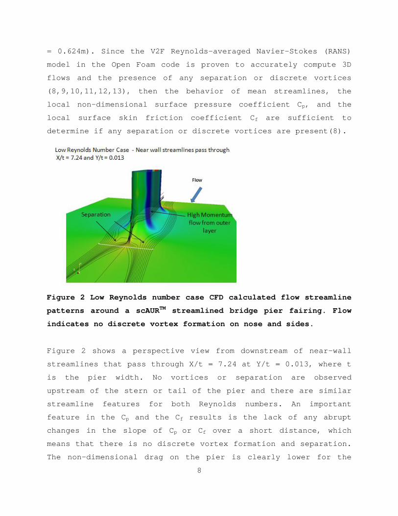
= 0.624m). Since the V2F Reynolds-averaged Navier-Stokes (RANS)
model in the Open Foam code is proven to accurately compute 3D
flows and the presence of any separation or discrete vortices
(8,9,10,11,12,13), then the behavior of mean streamlines, the
local non-dimensional surface pressure coefficient Cp, and the
local surface skin friction coefficient Cf are sufficient to
determine if any separation or discrete vortices are present(8).
Figure 2 Low Reynolds number case CFD calculated flow streamline
patterns around a scAURTM streamlined bridge pier fairing. Flow
indicates no discrete vortex formation on nose and sides.
Figure 2 shows a perspective view from downstream of near-wall
streamlines that pass through X/t = 7.24 at Y/t = 0.013, where t
is the pier width. No vortices or separation are observed
upstream of the stern or tail of the pier and there are similar
streamline features for both Reynolds numbers. An important
feature in the Cp and the Cf results is the lack of any abrupt
changes in the slope of Cp or Cf over a short distance, which
means that there is no discrete vortex formation and separation.
The non-dimensional drag on the pier is clearly lower for the
8
= 0.624m). Since the V2F Reynolds-averaged Navier-Stokes (RANS)
model in the Open Foam code is proven to accurately compute 3D
flows and the presence of any separation or discrete vortices
(8,9,10,11,12,13), then the behavior of mean streamlines, the
local non-dimensional surface pressure coefficient Cp, and the
local surface skin friction coefficient Cf are sufficient to
determine if any separation or discrete vortices are present(8).
Figure 2 Low Reynolds number case CFD calculated flow streamline
patterns around a scAURTM streamlined bridge pier fairing. Flow
indicates no discrete vortex formation on nose and sides.
Figure 2 shows a perspective view from downstream of near-wall
streamlines that pass through X/t = 7.24 at Y/t = 0.013, where t
is the pier width. No vortices or separation are observed
upstream of the stern or tail of the pier and there are similar
streamline features for both Reynolds numbers. An important
feature in the Cp and the Cf results is the lack of any abrupt
changes in the slope of Cp or Cf over a short distance, which
means that there is no discrete vortex formation and separation.
The non-dimensional drag on the pier is clearly lower for the
9
higher Reynolds number case because Cf is always lower and the
overall drag is an integral of the surface shearing stress over
the pier surface area. In addition, these results show lower
flow blockage than without the scAURTM and VorGAURTM products
because low velocity swirling high flow blockage vortices are
absent. As a result, water moves around a pier or abutment
faster near the river surface, producing a lower water level at
the bridge and lower over-topping frequencies on bridges during
flood conditions for any water level when no discrete vortices
are present.
Based on the past published work on scour and the experience of
AUR (9, 10, 11), more physical evidence and insights support the
idea that these scour vortex preventing devices will work better
at full scale than model scale. Scouring forces on river bed
materials are produced by pressure gradients and turbulent
shearing stresses, which are instantaneously unsteady. At higher
Reynolds numbers and sizes, pressure gradients and turbulent
fluctuation stresses are lower than at model scale, so scour at
the same flow speed is lower. Work by others (4,5,14) supports
the conclusion that scour predictive equations, developed
largely from laboratory data, overpredict scour on full-scale
underwater structures. Thus, the scAURTM and VorGAURTM work as
well or better in preventing the scouring vortices and any scour
at full scale as at the proven model scale. Other CFD by AUR,
which is discussed below, shows that scAURTM and VorGAURTM
products also prevent scouring vortices around bridge piers
downstream of bending rivers.
TASK III Flume Tests with Several Smaller Size Sediments at
Model Scale

10
Data on the performance of the scAURTM fairing and VorGAURTM VGs
were obtained using several smaller size sediments at model
scale in the AUR flume to prove the applicability of the designs
for fine sediments (8). All tests were at a flow speed of
0.66mps when incipient open bed scour of the pea gravel (3.2mm
to 6.3mm) was first observed. Melville (15) states that the
greatest equilibrium scour depth occurs around a circular pier
(width = t) when it is surrounded by uniform sediment at times
when the flow velocity equals the critical value, i.e.,
incipient conditions for open bed scour. Also, live bed scour
depth is never larger than incipient scour depth. Melville
states: "Recent data by Sheppard et al. (14)
demonstrate significant scour depth reductions for increasing
t/d50 when t/d50 > 50. Thus, local scour depths at field scale
may be significantly reduced from those observed in the
laboratory." The "t/d50" term is the ratio of pier width to
median grain diameter. A value of t/d50=50 was used, with a
range of sediments from 38.1 to 64.6.
Three sieved sand or gravel sizes were used to encompass this
range for previously reported flow conditions where scour will
be the greatest for the AUR t = 76.2mm wide model pier: Gravel
A: 1.18 to 1.4 mm; Gravel B: 1.4 to 1.7mm; Gravel C: 1.7 to
2mm. Usually smaller sediment scours before larger pea gravel.
No scour around the scAURTM model occurred for any of these black
slag gravel at speeds when the open bed pea gravel began to
scour (8) within the y/t = +/- 0.004 measurement uncertainty.
Task IV.A – Flume Tests of SCAURTM and VorGAURTM Concepts for a
Larger Class of Abutments
The performance of scAURTM and VorGAURTM concepts for wing-wall
11
and spill-through abutments was examined by model scale flume
tests at incipient open bed scour flow speeds of 0.66mps (8) and
show that scAURTM and VorGAURTM prevent the formation of scouring
vortices and scour.
Figure 3 shows surface oilflow results for a scAURTM modified
wing-wall abutment with VorGAURTM vortex generators (VGs)(8). The
mixture of yellow artist oil paint and mineral oil flows with
the skin friction lines. Yellow streaks are first painted about
perpendicular to the flow direction on a black painted surface.
The flow causes some oil to be carried downstream in a local
flow direction, which can be observed against the black painted
surface. Figure 3 clearly shows that the effects of the scAURTM
with VorGAURTM are to bring lower velocity flow up from the flume
bottom and prevent the scour around the bottom of the abutment.
With a scAURTM modified wing-wall abutment with VGs, there is not
only no scour around the model base (Figure 4), but there is no
open bed scour hole farther downstream of the model around x/L =
2. This is because the VGs generate counter-rotating vortices
which diffuse and reduce the strength of the free-surface
generated vortex, which caused the scour hole farther downstream
of the model for the untreated case.
Flow and scour depth results are given for flume tests without
and with scAURTM modified spill-through abutment with VorGAURTM
VGs under the same 0.66mps flow (8). The surface oilflow (Figure
5) clearly shows that the scAURTM and VorGAURTM products bring
lower velocity flow up from the flume bottom and prevent scour
around the bottom of the abutment. Deep scour holes occur around
the foundation for the untreated spill-through abutment (8).
12
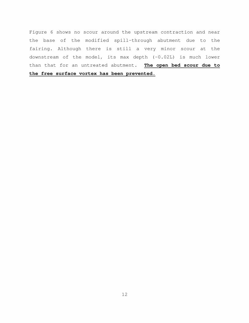
Figure 6 shows no scour around the upstream contraction and near
the base of the modified spill-through abutment due to the
fairing. Although there is still a very minor scour at the
downstream of the model, its max depth (-0.02L) is much lower
than that for an untreated abutment. The open bed scour due to
the free surface vortex has been prevented.

13
Figure 3. Surface oilflow results for the modified wing-wall
abutment model with VGs. Flow from right to left. The upward
streaks show that scAURTM and VorGAURTM products cause the flow to
move up the abutment. The gray region is produced by a mixture
of the oilflow material and waterborne substances at the free
surface.
14
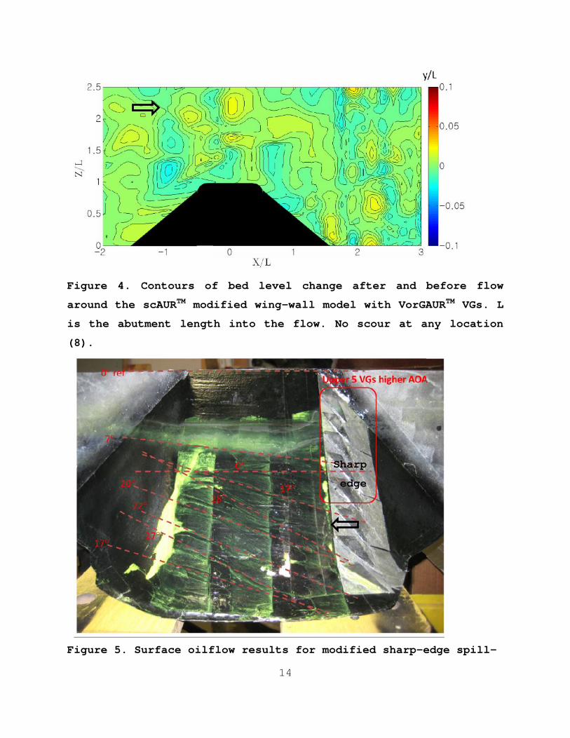
Figure 4. Contours of bed level change after and before flow
around the scAURTM modified wing-wall model with VorGAURTM VGs. L
is the abutment length into the flow. No scour at any location
(8).
Figure 5. Surface oilflow results for modified sharp-edge spill-
Sharp
edge
14
Figure 4. Contours of bed level change after and before flow
around the scAURTM modified wing-wall model with VorGAURTM VGs. L
is the abutment length into the flow. No scour at any location
(8).
Figure 5. Surface oilflow results for modified sharp-edge spill-
Sharp
edge
14
Figure 4. Contours of bed level change after and before flow
around the scAURTM modified wing-wall model with VorGAURTM VGs. L
is the abutment length into the flow. No scour at any location
(8).
Figure 5. Surface oilflow results for modified sharp-edge spill-
Sharp
edge

15
through abutment model with 8 VGs. Note that scAURTM and VorGAURTM
cause the flow to move up the abutment as it moves downstream,
bringing low speed fluid from the bottom of the river and
preventing scour. The gray region is produced by a mixture of
the oilflow material and waterborne substances at the free
surface (8).
Figure 6. Contours of bed level change after and before flow
around the scAURTM modified sharp-edge spill-through model with
VorGAURTM VGs (L = 229mm). No scour at any location (8).
TASK IV.B – Flume Tests of Foundations Exposed by Open Bed Scour
Aspects of the scAURTM and VorGAURTM design features have been
expanded for use around the foundation (US Patent 9,453,319,
Sept. 27, 2016) to protect the foundation from the effects of
contraction scour, long term degradation scour, settlement and
differential settlement of footers, undermining of the concrete
scAURTM segments, and effects of variable surrounding bed levels.
As all AUR flume studies have shown (8), under these conditions
scour of the open bed material occurs at a lower river speed
before scour of the material around the base of the scAURTM
16
fairing occurs.
This means that scour of the river bed away from the scAURTM
protected pier or abutment occurs first and that the river bed
level will be lower away from the pier or abutment. If a pier or
abutment foundation is exposed, it will still have a higher
immediate surrounding river bed level than farther away. Even
so, one would like to further arrest scour around the foundation
to prevent high speed open bed scour from encroaching on the
river bed material next to the foundation.
Second, if the front of the foundation of a pier or abutment is
exposed to approach flows, then a foundation horseshoe or
scouring vortex is formed at the front which will cause local
scour around the pier or abutment. This suggests that a curved-
top ramp be mounted in front of the foundation that prevents the
formation of this foundation horseshoe vortex.
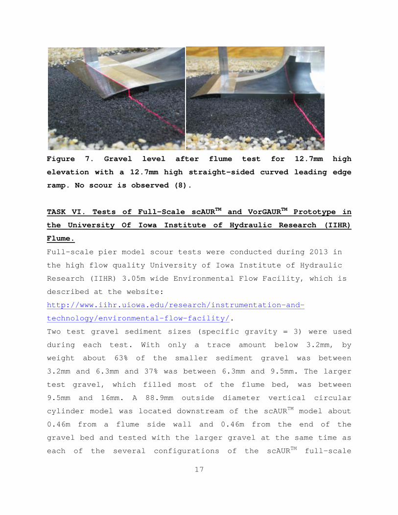
Based on these facts, flume tests were conducted with 3
foundation leading edge ramp configurations: (1) an exposed
rectangular foundation with no front ramp protection, (2) an
upstream curved-top foundation ramp with trapezoidal span-wise
edges to produce a stream-wise vortex to bring open bed
materials toward the foundation, and (3) a curved-top upstream
foundation ramp with straight span-wise edges. Gravel A was
used around the foundation since it was the smallest gravel
tested in this project in Task III. In summary, all of these
foundation tests show that a leading edge straight-sided curved
top ramp prevents scour around a foundation when there is open
bed scour, as shown in Figure 7.
17
Figure 7. Gravel level after flume test for 12.7mm high
elevation with a 12.7mm high straight-sided curved leading edge
ramp. No scour is observed (8).
TASK VI. Tests of Full-Scale scAURTM and VorGAURTM Prototype in
the University Of Iowa Institute of Hydraulic Research (IIHR)
Flume.
Full-scale pier model scour tests were conducted during 2013 in
the high flow quality University of Iowa Institute of Hydraulic
Research (IIHR) 3.05m wide Environmental Flow Facility, which is
described at the website:
http://www.iihr.uiowa.edu/research/instrumentation-and-
technology/environmental-flow-facility/.
Two test gravel sediment sizes (specific gravity = 3) were used
during each test. With only a trace amount below 3.2mm, by
weight about 63% of the smaller sediment gravel was between
3.2mm and 6.3mm and 37% was between 6.3mm and 9.5mm. The larger
test gravel, which filled most of the flume bed, was between
9.5mm and 16mm. A 88.9mm outside diameter vertical circular
cylinder model was located downstream of the scAURTM model about
0.46m from a flume side wall and 0.46m from the end of the
gravel bed and tested with the larger gravel at the same time as
each of the several configurations of the scAURTM full-scale
18
model to show that the flow conditions cause scour with the
cylinder. Test runs continued until after the cylinder scour
reached equilibrium conditions with no further observed scour.
With the larger gravel, the equilibrium scour hole was 76mm deep
in front of the cylinder and extended 89mm upstream with a span-
wise width of 0.28m.
Measurements were obtained for the scour depth around the base
of the model after the flume was drained using photos of laser
sheet surface locations (6), surface oilflows over the model to
determine the local surface flow direction, and some pitot tube
flow velocity data in front of and around the model. Five full-
scale model configurations were tested with the larger and
smaller gravel on opposite sides of the model (8): Configuration
A, a full-scale 10.16m long 1.42m wide scAURTM model with 6
VorGAURTM vortex generators with three 2.44m side sections on
each side, as shown in Figure 8, flush with the gravel bed top;
Configuration B, same as Configuration A, but with 8 VorGAURTM
vortex generators; Configuration C, same as B, but with the
straight-sided leading edge curved-top ramp like in Figure 7
above and the model 76mm above the surrounding gravel bed;
Configuration D, full-scale scAURTM with 8 VorGAURTM vortex
generators with only one side section on each side and flush
with the gravel bed; Configuration E, full-scale scAURTM nose and
tail sections with 4 nose section VorGAURTM vortex generators
with no side sections.

19
Figure 8. Photo from upstream of the AUR full-scale 10.16m long
1.42m wide scAURTM with VorGAURTM vortex generators model in the
IIHR Environmental Flume Facility with three 2.44m side sections
on each side for Configurations A and B. Small and large gravel
on opposite sides are flush with the edge of the model.
In summary, the full-scale model tests confirmed that there was
no scour around the front and sides for each Configuration with
either the smaller or larger gravel, as was also observed at
model scale. Only a small amount of scour of the smaller gravel
was observed downstream, which was due to full-scale model width
to flume width (0.15 to 1/3) flow blockage effects, which were
comparable to flow blockage results for the 1/7 size models in
the AUR flume (8).
TASK VII. Cost-effective Manufacturing and Installation of
20
scAURTM and VorGAURTM Products
Before this project, AUR performed a cost-benefit analysis of
scAURTM with VorGAURTM as compared to current scour
countermeasures (8). Published information shows that current
expenses are required for scour monitoring, evaluation, and
anti-scour mitigation design and construction, usually with rip-
rap. For a bridge closed due to scour, the cost to motorists
due to traffic detours is estimated to be as great as all other
costs combined, but were not included in the analysis (8).
There is no situation where scAURTM and VorGAURTM products cost
more than current countermeasures. As shown in Figure 9 for
stainless steel retrofits. There is no situation where any type
of scour is worse with the use of the scAURTM and VorGAURTM
products than without them. The more frequent that scouring
floods occur, the more cost effective are scAURTM and VorGAURTM.
Clearly, scAURTM and VorGAURTM products are practical and cost-
effective for US highway bridges (8).
In order to further reduce costs and increase the versatility of
the scAURTM and VorGAURTM products, multiple manufacturing
alternatives were considered. The required labor, materials,
time, logistics, and practical issues were examined and used to
evaluate manufacturing alternatives (8). Since the NCHRP-IDEA-
162 project, detailed full-scale cost-effective versions have
been developed for installation.
Retrofit to an Existing Bridge
An installed welded stainless steel (SS) scAURTM retrofit bridge
fairing is cost-effective, being about half of all costs for

21
Figure 9. Economics of stainless steel retrofits.
precast or cast-in-place concrete manufacturing and installation
(8). Its corrosion resistance gives it a lifetime of 100 years
even in seawater environments, using a proper thickness,
construction methods, and type of SS. It is an effective way to
reduce weight and the cost associated with casting custom
reinforced concrete structures. Another benefit is that the SS
VorGAURTM vortex generators can be welded directly onto the side
sections instead of having to be integrated into the rebar cage
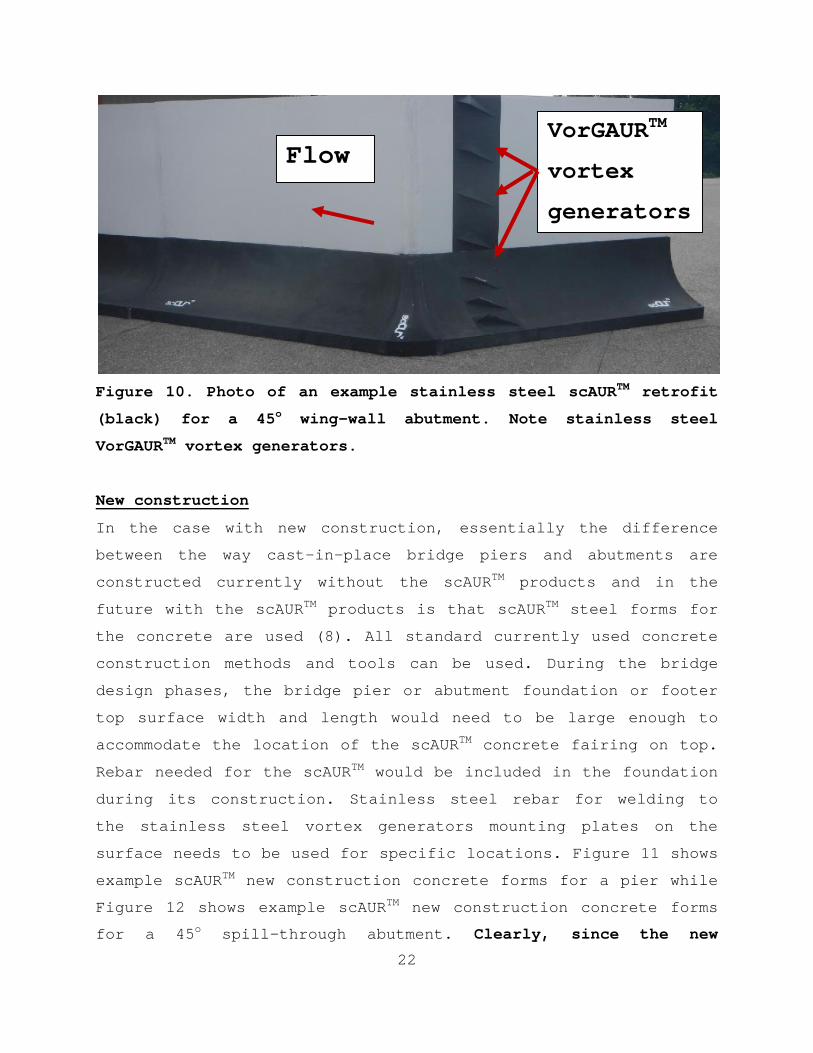
of the reinforced concrete structure. Figure 10 is an example of
a retrofitted wing-wall abutment. Even for bridges with little
life left, current temporary countermeasures are much more
expensive when the present value of future expenses is
considered (8).
22
Figure 10. Photo of an example stainless steel scAURTM retrofit
(black) for a 45o wing-wall abutment. Note stainless steel
VorGAURTM vortex generators.
New construction
In the case with new construction, essentially the difference
between the way cast-in-place bridge piers and abutments are
constructed currently without the scAURTM products and in the
future with the scAURTM products is that scAURTM steel forms for
the concrete are used (8). All standard currently used concrete
construction methods and tools can be used. During the bridge
design phases, the bridge pier or abutment foundation or footer
top surface width and length would need to be large enough to
accommodate the location of the scAURTM concrete fairing on top.
Rebar needed for the scAURTM would be included in the foundation
during its construction. Stainless steel rebar for welding to
the stainless steel vortex generators mounting plates on the
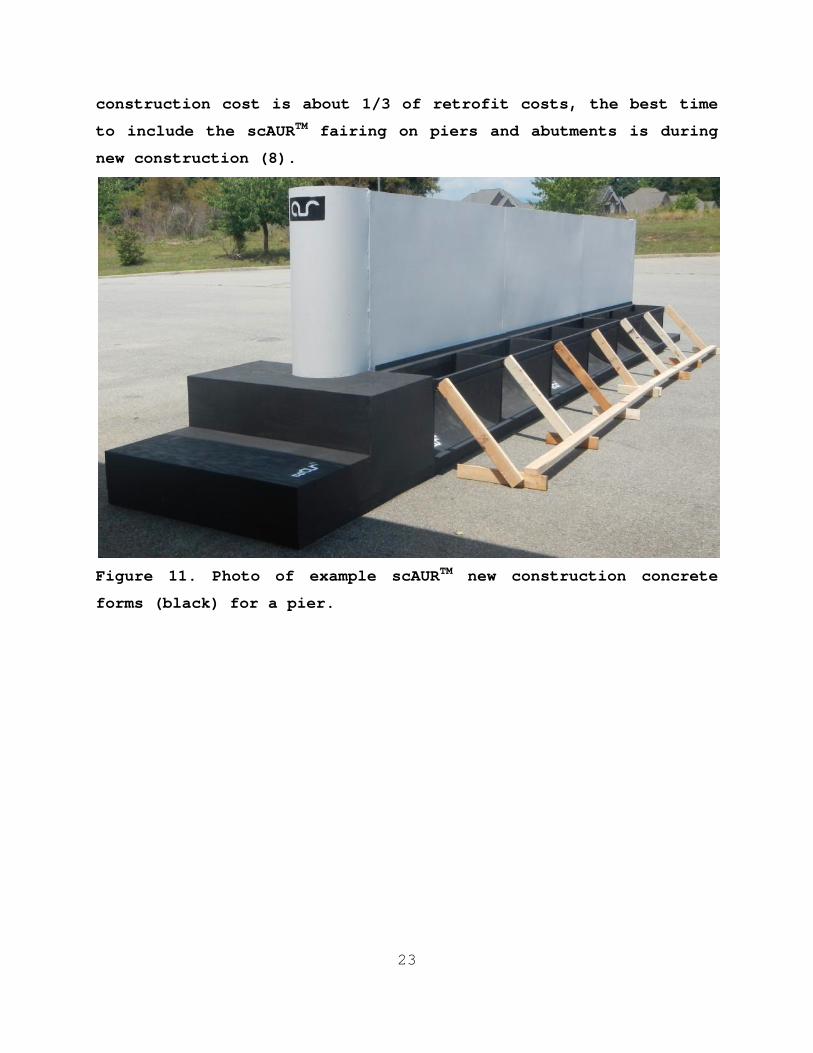
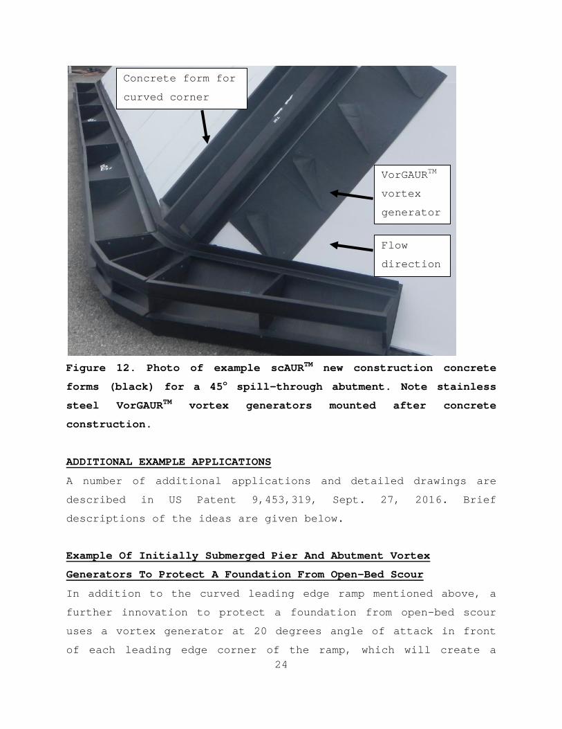
surface needs to be used for specific locations. Figure 11 shows
example scAURTM new construction concrete forms for a pier while
Figure 12 shows example scAURTM new construction concrete forms
for a 45o spill-through abutment. Clearly, since the new
VorGAURTM
vortex
generators
Flow
23
construction cost is about 1/3 of retrofit costs, the best time
to include the scAURTM fairing on piers and abutments is during
new construction (8).
Figure 11. Photo of example scAURTM new construction concrete
forms (black) for a pier.
24
Figure 12. Photo of example scAURTM new construction concrete
forms (black) for a 45o spill-through abutment. Note stainless
steel VorGAURTM vortex generators mounted after concrete
construction.
ADDITIONAL EXAMPLE APPLICATIONS
A number of additional applications and detailed drawings are
described in US Patent 9,453,319, Sept. 27, 2016. Brief
descriptions of the ideas are given below.
Example Of Initially Submerged Pier And Abutment Vortex
Generators To Protect A Foundation From Open-Bed Scour
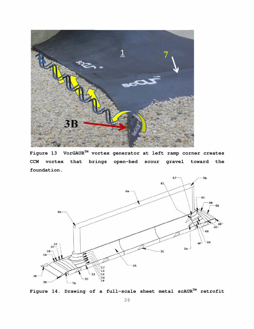
In addition to the curved leading edge ramp mentioned above, a
further innovation to protect a foundation from open-bed scour
uses a vortex generator at 20 degrees angle of attack in front
of each leading edge corner of the ramp, which will create a
VorGAURTM
vortex
generator
sFlow
direction
Concrete form for
curved corner

25
vortex that brings available loose open-bed scour materials
toward the pier or abutment foundation to protect the pier or
abutment, as shown in Figure 13 for a pier. Like for the ramp,
when there is no high velocity flow and the curved leading edge
ramp (7 on figure) is covered with river bed material, the
vortex generators (3B on figure) are also covered with bed
material. When the water flow speed approaching the pier or
abutment is large enough to cause open-bed scour, the bed
material over the curved leading edge ramp and the vortex
generators will eventually be removed exposing both the ramp and
vortex generators. Both the curved leading edge ramp and the
vortex generators create vortices that bring loose open-bed
material toward the foundation to further protect it from scour.
Another innovation uses vortex generators (VG) mounted on the
sides of the foundation to bring more available loose open-bed
scour materials toward the pier or abutment foundation to
protect further the pier or abutment. These vortex generators
are initially submerged below the surface of the river bed, but
are exposed when there is high velocity flow and open-bed scour.
Properly oriented, they create vortices that bring open–bedscour material towards the foundation for protection.
Figures 14, 15, and 16 show patent drawings of the piece-wise
continuous stainless steel retrofits to a pier, wing-wall
abutment, and spill-through abutment. Note the use of vortex
generators around the foundation to prevent scour when there is
open bed scour.
26
Figure 13 VorGAURTM vortex generator at left ramp corner creates
CCW vortex that brings open-bed scour gravel toward the
foundation.
Figure 14. Drawing of a full-scale sheet metal scAURTM retrofit
26
Figure 13 VorGAURTM vortex generator at left ramp corner creates
CCW vortex that brings open-bed scour gravel toward the
foundation.
Figure 14. Drawing of a full-scale sheet metal scAURTM retrofit
26
Figure 13 VorGAURTM vortex generator at left ramp corner creates
CCW vortex that brings open-bed scour gravel toward the
foundation.
Figure 14. Drawing of a full-scale sheet metal scAURTM retrofit
27
fairing with VorGAURTM for a pier (6A) with piece-wise continuous
concave-convex curvature surfaces, with individual sections or
pieces of nose surface (1A), (1B), (1C), (1D), (1E), (1F),
(1G),(1H),(1I),(1J); for the side of the pier (2A); and the
stern or tail, with individual sections or pieces of surface
(4A), (4B), (4C), (4D), (4E), (4F),(4G),(4H),(4I), and (4J),
within definable tolerances that produce the same effects as
continuous concave-convex-curvature surfaces. The leading edge
ramp (7A) and pier foundation protecting VGs (3B) mounted on
leading edge plate (7B) and (3C) mounted on (1E) and (2A)
protect the foundation from open-bed scour.
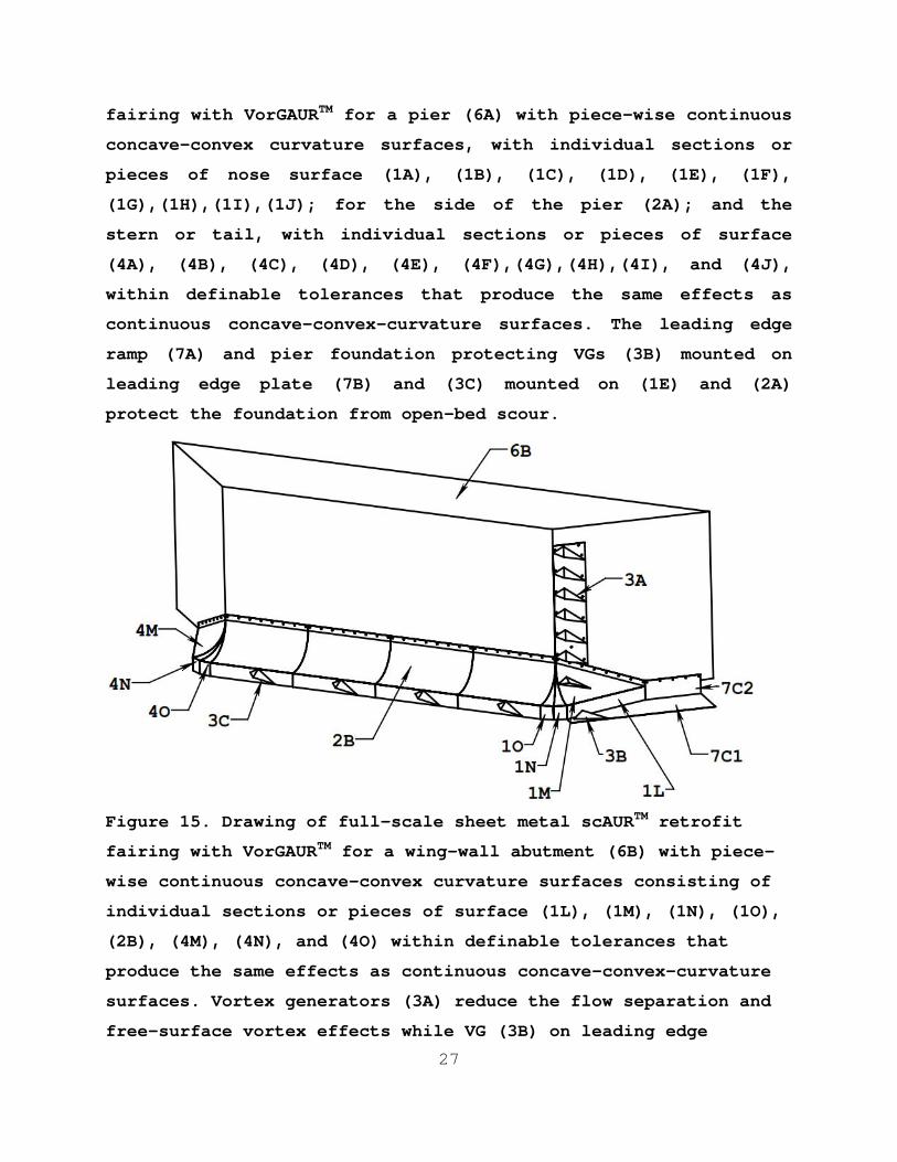
Figure 15. Drawing of full-scale sheet metal scAURTM retrofit
fairing with VorGAURTM for a wing-wall abutment (6B) with piece-
wise continuous concave-convex curvature surfaces consisting of
individual sections or pieces of surface (1L), (1M), (1N), (1O),
(2B), (4M), (4N), and (4O) within definable tolerances that
produce the same effects as continuous concave-convex-curvature
surfaces. Vortex generators (3A) reduce the flow separation and
free-surface vortex effects while VG (3B) on leading edge
28
horizontal plate (7C1) that is connected to vertical plate (7C2)
and VG (3C) protect the foundation from open-bed scour.
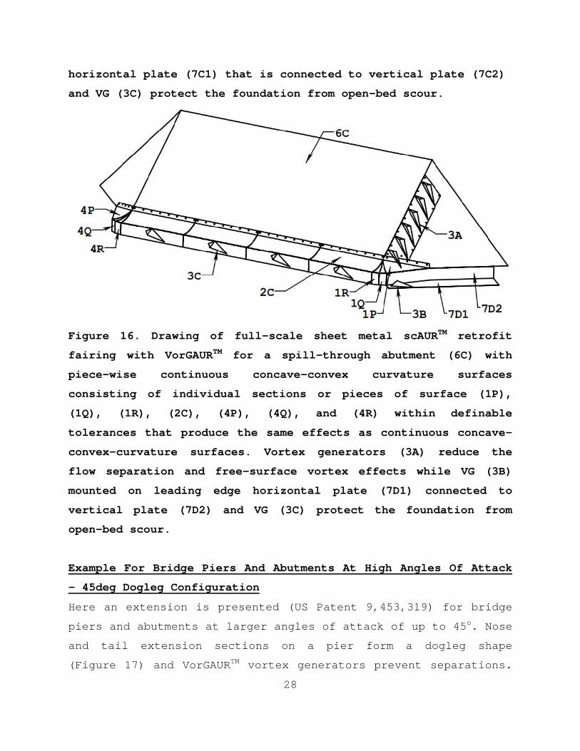
Figure 16. Drawing of full-scale sheet metal scAURTM retrofit
fairing with VorGAURTM for a spill-through abutment (6C) with
piece-wise continuous concave-convex curvature surfaces
consisting of individual sections or pieces of surface (1P),
(1Q), (1R), (2C), (4P), (4Q), and (4R) within definable
tolerances that produce the same effects as continuous concave-
convex-curvature surfaces. Vortex generators (3A) reduce the
flow separation and free-surface vortex effects while VG (3B)
mounted on leading edge horizontal plate (7D1) connected to
vertical plate (7D2) and VG (3C) protect the foundation from
open-bed scour.
Example For Bridge Piers And Abutments At High Angles Of Attack
- 45deg Dogleg Configuration
Here an extension is presented (US Patent 9,453,319) for bridge
piers and abutments at larger angles of attack of up to 45o. Nose
and tail extension sections on a pier form a dogleg shape
(Figure 17) and VorGAURTM vortex generators prevent separations.
29
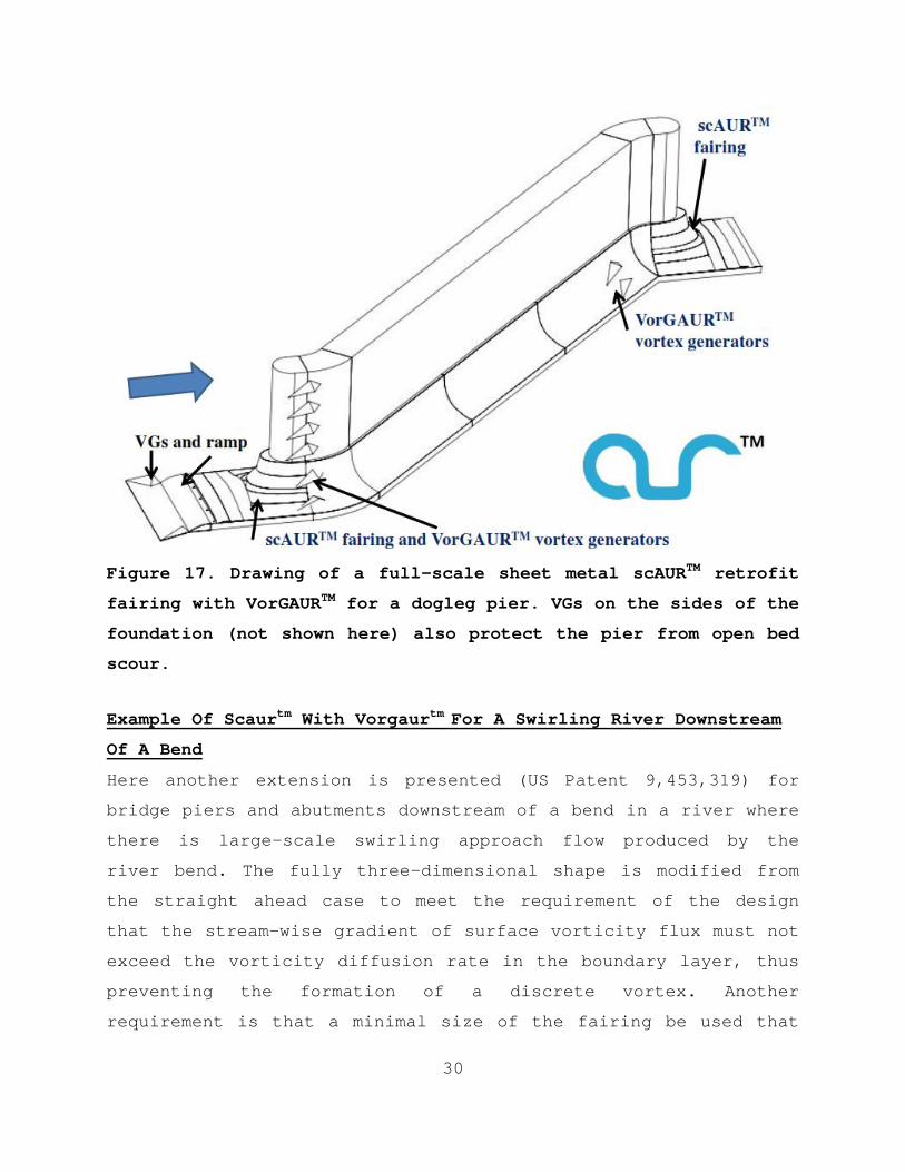
The centerline of the piece-wise continuous curved pier nose and
tail extensions and the nose and tail of the scAURTM are aligned
with the on-coming flow direction. VorGAURTM vortex generators
are used to energize the near-wall flow upstream of the adverse
pressure gradient regions around the pier and prevent separation
and scour. The leading edge ramp and pier foundation protecting
VGs mounted on leading edge plate and the sides of the
foundation protect the foundation from open-bed scour.
Model scale experiments in the AUR flume were performed that
confirm that this design prevents scour. The VGs are attached on
both front and rear fairings as shown in Figure 17. The VGs are
76mm long and 19mm high. The free-stream velocity is 0.58m/s and
the flow speed near the VGs on the fairings is about 0.61m/s,
which caused scour when the VGs were not used. There was no
scour around the model.
Manufacturing and installation processes and methods would be
the same as for bridges at lower angles of attack that do not
need the dogleg. However there are increases in costs due to the
addition of the additional components required for the SS dogleg
on a pier (8).
30
Figure 17. Drawing of a full-scale sheet metal scAURTM retrofit
fairing with VorGAURTM for a dogleg pier. VGs on the sides of the
foundation (not shown here) also protect the pier from open bed
scour.
Example Of Scaurtm With Vorgaurtm For A Swirling River Downstream
Of A Bend
Here another extension is presented (US Patent 9,453,319) for
bridge piers and abutments downstream of a bend in a river where
there is large-scale swirling approach flow produced by the
river bend. The fully three-dimensional shape is modified from
the straight ahead case to meet the requirement of the design
that the stream-wise gradient of surface vorticity flux must not
exceed the vorticity diffusion rate in the boundary layer, thus
preventing the formation of a discrete vortex. Another
requirement is that a minimal size of the fairing be used that
31
meets the first requirement.
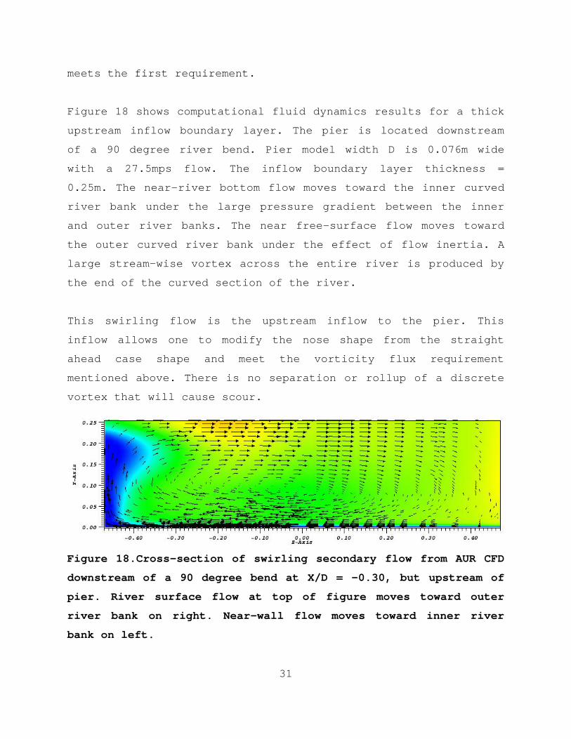
Figure 18 shows computational fluid dynamics results for a thick
upstream inflow boundary layer. The pier is located downstream
of a 90 degree river bend. Pier model width D is 0.076m wide
with a 27.5mps flow. The inflow boundary layer thickness =
0.25m. The near-river bottom flow moves toward the inner curved
river bank under the large pressure gradient between the inner
and outer river banks. The near free-surface flow moves toward
the outer curved river bank under the effect of flow inertia. A
large stream-wise vortex across the entire river is produced by
the end of the curved section of the river.
This swirling flow is the upstream inflow to the pier. This
inflow allows one to modify the nose shape from the straight
ahead case shape and meet the vorticity flux requirement
mentioned above. There is no separation or rollup of a discrete
vortex that will cause scour.
Figure 18.Cross-section of swirling secondary flow from AUR CFD
downstream of a 90 degree bend at X/D = -0.30, but upstream of
pier. River surface flow at top of figure moves toward outer
river bank on right. Near-wall flow moves toward inner river
bank on left.
32
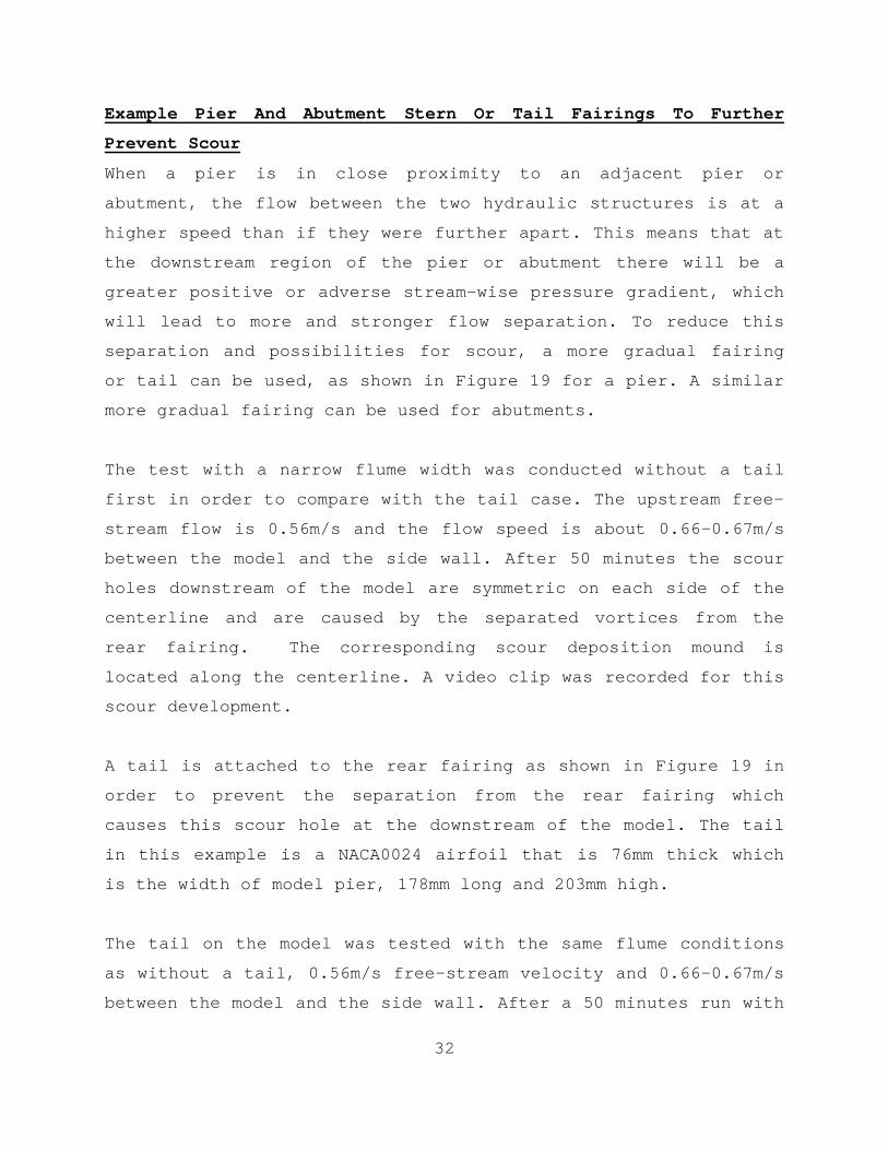
Example Pier And Abutment Stern Or Tail Fairings To Further
Prevent Scour
When a pier is in close proximity to an adjacent pier or
abutment, the flow between the two hydraulic structures is at a
higher speed than if they were further apart. This means that at
the downstream region of the pier or abutment there will be a
greater positive or adverse stream-wise pressure gradient, which
will lead to more and stronger flow separation. To reduce this
separation and possibilities for scour, a more gradual fairing
or tail can be used, as shown in Figure 19 for a pier. A similar
more gradual fairing can be used for abutments.
The test with a narrow flume width was conducted without a tail
first in order to compare with the tail case. The upstream free-
stream flow is 0.56m/s and the flow speed is about 0.66-0.67m/s
between the model and the side wall. After 50 minutes the scour
holes downstream of the model are symmetric on each side of the
centerline and are caused by the separated vortices from the
rear fairing. The corresponding scour deposition mound is
located along the centerline. A video clip was recorded for this
scour development.
A tail is attached to the rear fairing as shown in Figure 19 in
order to prevent the separation from the rear fairing which
causes this scour hole at the downstream of the model. The tail
in this example is a NACA0024 airfoil that is 76mm thick which
is the width of model pier, 178mm long and 203mm high.
The tail on the model was tested with the same flume conditions
as without a tail, 0.56m/s free-stream velocity and 0.66-0.67m/s
between the model and the side wall. After a 50 minutes run with

33
the same flow speed as before, there are only very minor scour
holes generated at the downstream of the model.
Figure 19. Drawing of full-scale sheet metal retrofit scAURTM
with VorGAURTM vortex generators for a pier with tail or stern.
Vortex generators reduce the flow separation and free-surface
vortex effects while VGs (not shown here on foundation) and ramp
protect the foundation from open-bed scour.
CONCLUSIONS
Local scour of bridge piers and abutments is a common cause of
highway bridge failures. All currently used countermeasures are
temporary and do not prevent the root cause of local scour –discrete large-scaled vortices formed by separations on
underwater structures. Using the knowledge of how to prevent the
34
formation of discrete vortices, prior to the NCHRP-IDEA-162
project, AUR developed, proved using model-scale tests, and
patented new local-scouring-vortex-prevention products that are
practical cost-effective long-term permanent solutions to the
bridge pier and abutment local scour problem. In the NCHRP
Project and later work, work on the effect of pier size or scale
and model flume tests for other sediments, other abutment
designs, and for open bed scour conditions showed that the
products prevent scouring vortices and scour. Full-scale
prototypes were successfully tested and cost-effective
manufacturing and installation plans were developed. The present
value cost of these products over the life of a bridge are an
order of magnitude cheaper than current scour countermeasures.
Concrete forms for new bridges and stainless steel retrofit
versions for existing bridges are now available. Plans for
installation these products on scour-critical bridges are
underway.
Acknowledgments
The scAURTM and VorGAURTM were developed first with IR&D funding
from AUR, Inc. The new work here was partially supported as
Project NCHRP-162 from the NCHRP-IDEA program. The authors
appreciate the endorsements and involvement from New Hampshire,
Texas, and Virginia DOTs for the NCHRP program.
References
1. Lagasse, P., Zevenbergen, L., Schall, J., and Clopper, P.,
Bridge Scour and Stream Instability Countermeasures. FHWA
Technical Report Hydraulic Engineering Circular (HEC)-23, 2001.
2. Flint, M. M., Fringer, O.,Billington, S.L., Freyberg,D., and
Diffenbaugh, N. S., 2017 Historical Analysis of Hydraulic Bridge
35
Collapses in the Continental United States, ASCE Journal of
Infrastructure Systems, 2017, 23(3),ASCE, ISSN 1076-0342.
3. Briaud, Jean-Louis, Monitoring Scour Critical Bridges, NCHRP
Synthesis 396, 2006.
4. Ettema, R., Yoon, Byungman, Nakato, Tatsuaki and Muste,
Marian, A review of scour conditions and scour-estimation
difficulties for bridge abutments, KSCE Journal of Civil
Engineering, Volume 8, Number 6, Pages 643-65, 2004.
5. Sheppard, D.M., Demir, H., and Melville, B., Scour at Wide
Piers and Long Skewed Piers, NCHRP-Report 682, 2011.
6. Tian, Q.Q., Simpson, R.L., and Lowe, K.T., A laser-based
optical approach for measuring scour depth around hydraulic
structures, 5th International Conference on Scour and Erosion,
ASCE, San Francisco, Nov. 7-11, 2010.
7. Barkdoll, B.D., Ettema, R., and B. W. Melville,
Countermeasures to Protect Bridge Abutments from Scour, NCHRP
Report 587, 2007.
8. Simpson, R. L., Unabridged Report on Full-Scale Prototype
Testing and Manufacturing and Installation Plans for New Scour-
Vortex-Prevention scAURTM and VorGAURTM Products for a
Representative Scour-critical Bridge, AUR, Inc., Internal
Report NCHRP-162, July 2013.
9. Simpson, R.L. Turbulent Boundary Layer Separation, Annual
Review of Fluid Mechanics, Vol. 21, pp.205-234, 1989.
10. Simpson, R.L., Aspects of Turbulent Boundary Layer
Separation, Progress in Aerospace Sciences, Vol.32, pp.457 –521, 1996.
11. Simpson, R. L., Junction Flows, Annual Review of Fluid
Mechanics, Vol. 33, pp. 415-443, 2001.
12. Durbin, P.A. and Petterson Reif, B.A., Statistical Theory
and Modeling for Turbulent Flows, Wiley, 2001.
36
13. Simpson, R.L., “Some Observations on the Structure andModeling of 3-D Turbulent Boundary Layers and Separated Flow,”Invited Plenary Lecture, Turbulent Shear Flow Phenomena-4,
Williamsburg, Va, June 27-29, 2005.
14. Sheppard, D.M., Odeh,M., Glasser,T., “Large Scale Clear-Water Local Pier Scour Experiments,” J. Hydraulic Eng., ASCE,
Vol. 130, pp. 957 -063, 2004.
15. Melville, B., “The Physics of Local Scour at Bridge Piers,”4th International Conference on Scour and Erosion, Tokyo, Japan,
2008.