Embed Size (px)
Citation preview
Instructions for Use - EN
Titan
Science made smarter
8100
759
D-0
1006
08-H
– 2
019/
04


Table of contents 1 Introduction ....................................................................................................................................... 1
1.1 About this manual ...........................................................................................................................1 1.2 Intended use ...................................................................................................................................1 1.3 Product description .........................................................................................................................1
1.3.1 Probe, transducers and cable configurations ......................................................................4 1.3.2 The preamplifer cable ..........................................................................................................4 1.3.3 Contra phone (for acoustic reflexes only) ............................................................................4
1.4 Warnings ........................................................................................................................................5 1.5 Data protection ...............................................................................................................................5
2 Unpacking and installation .............................................................................................................. 7
2.1 Unpacking and inspection ..............................................................................................................7 2.2 Markings .........................................................................................................................................8 2.3 Hardware installation ......................................................................................................................9 2.4 Installing the cradle ..................................................................................................................... 11 2.5 Mounting a cradle on the wall ..................................................................................................... 13 2.6 Cradle indication lights ................................................................................................................ 14 2.7 Calibration cavities and issues .................................................................................................... 14 2.8 Installing the Sanibel MPT-II thermal printer ............................................................................... 15
2.8.1 Battery pack insertion and charging ................................................................................. 15 2.8.2 Installing Paper in the Thermal Printer ............................................................................. 15 2.8.3 Turning the printer on and off ............................................................................................ 15 2.8.4 Connecting the printer to the Titan via cable .................................................................... 16 2.8.5 Connecting the printer to the Titan via Bluetooth .............................................................. 16
2.9 Installing Titan and its battery ..................................................................................................... 17 2.9.1 Charging the battery ......................................................................................................... 17 2.9.2 Battery Lifetime and Charging Time ................................................................................. 18
2.10 Changing probes and extension cords on the Titan ................................................................... 19 2.11 Connecting transducers to the shoulder box and preamplifier ................................................... 20 2.12 Placing and using the Long Clinical Extension Cable (Shoulder Box) or preamplifier cable ...... 20 2.13 Placing the montage-indication stickers on the preamplifier ....................................................... 21 2.14 Use of the E-A-RTONE ABR transducer with ear tips, foam inserts or EarCups
(ABRIS440 only) ......................................................................................................................... 22 2.15 Use of the IP30 ABR transducer with ear tips, foam inserts or EarCups (ABRIS440 only) ........ 23 2.16 Safety Precautions to take when connecting the Titan ............................................................... 23 2.17 Software installation .................................................................................................................... 30 2.18 Installation of the driver ............................................................................................................... 32 2.19 Standalone installation of Titan Suite .......................................................................................... 33 2.20 License ........................................................................................................................................ 33 2.21 Creating a Bluetooth connection for PC controlled measurements ............................................ 33 2.22 Bluetooth installation (Windows® 7) ............................................................................................ 34 2.23 Bluetooth installation (Windows® 8 & 10) .................................................................................... 36
3 Operating instructions ................................................................................................................... 39
3.1 Handling and selection of ear tips ............................................................................................... 40 3.2 Switching the Titan on and off ..................................................................................................... 40 3.3 Probe status ................................................................................................................................ 41 3.4 Titan handheld operation panel ................................................................................................... 41 3.5 Operating Titan in handheld mode .............................................................................................. 42
3.5.1 Startup ............................................................................................................................... 42 3.5.2 Battery ............................................................................................................................... 42 3.5.3 Test screen ....................................................................................................................... 42 3.5.4 Done screen ...................................................................................................................... 44 3.5.5 Select Client & Save ......................................................................................................... 45 3.5.6 Edit New Screen ............................................................................................................... 46

3.5.7 View Clients Screen .......................................................................................................... 46 3.5.8 View Details Screen .......................................................................................................... 47 3.5.9 Edit Details Screen ........................................................................................................... 47 3.5.10 View Sessions Screen ...................................................................................................... 47 3.5.11 View Session Screen ........................................................................................................ 48 3.5.12 Select Protocol Screen ..................................................................................................... 48 3.5.13 Setup Screen .................................................................................................................... 49 3.5.14 Language Screen .............................................................................................................. 49 3.5.15 Date & Time Screen .......................................................................................................... 49 3.5.16 Titan Screen ...................................................................................................................... 50 3.5.17 Printer Screen ................................................................................................................... 50 3.5.18 Clinic Info Screen .............................................................................................................. 50 3.5.19 License Screen ................................................................................................................. 51 3.5.20 About Screen .................................................................................................................... 51
3.6 Probe test for TEOAE.................................................................................................................. 52 3.6.1 Performing the probe test ................................................................................................. 52 3.6.2 Functioning probe ............................................................................................................. 53 3.6.3 Faulty probe ...................................................................................................................... 53
3.7 Operating in PC controlled mode ................................................................................................ 55 3.7.1 PC power configuration ..................................................................................................... 55 3.7.2 Starting from OtoAccess® ................................................................................................ 55 3.7.3 Starting from Noah 4 ......................................................................................................... 55 3.7.4 Crash report ...................................................................................................................... 55
3.8 PC controlled operation via Bluetooth ......................................................................................... 56 3.9 Using the main tab ...................................................................................................................... 57 3.10 Using the IMP module ................................................................................................................. 62 3.11 Using the 3D Tympanometry and Absorbance test .................................................................... 66 3.12 Using the ABRIS module ............................................................................................................ 70 3.13 Using the DPOAE module ........................................................................................................... 74 3.14 Using the TEOAE tab .................................................................................................................. 81 3.15 Using the Print Wizard................................................................................................................. 87
4 Maintenance .................................................................................................................................... 89
4.1 General maintenance procedures ............................................................................................... 89 4.2 Cleaning the probe tip ................................................................................................................. 90 4.3 Concerning repair ........................................................................................................................ 91 4.4 Warranty ...................................................................................................................................... 91
5 General technical specification .................................................................................................... 93
5.1 Titan hardware – technical specifications ................................................................................... 93 5.2 Electromagnetic compatibility (EMC) ........................................................................................ 103

D-0100608-H – 2019/04 Titan - Instructions for Use - EN Page 1
1 Introduction About this manual
This manual is valid for the Titan version 3.4.1 The product is manufactured by:
Interacoustics A/S Audiometer Allé 1 5500 Middelfart Denmark Tel.: +45 6371 3555 Fax: +45 6371 3522 E-mail: [email protected] Web: www.interacoustics.com
Intended use The Titan with IMP440 Impedance System is an electroacoustic test instrument that produces controlled levels of test tones and signals intended for use in conduction diagnostic hearing evaluations and assisting in the diagnosis of possible otologic disorders. It features tympanometry and acoustic reflexes. It also measures various acoustic properties of the ear, namely power reflectance, power absorption, transmittance, reflectance group delay, complex acoustic impedance and admittance, and equivalent ear canal volume. These measures allow the evaluation of the functional condition of the middle and outer ear. The target population for Titan with IMP440 includes all ages. The Titan with DPOAE440 is intended for use in the audiologic evaluation and documentation of ear disorders using Distortion Product Otoacoustic Emissions. The target population for Titan with DPOAE440 includes all ages. The Titan with ABRIS4401 is intended for use in the audiologic evaluation and documentation of ear and nerve disorders using auditory evoked potentials from the inner ear, the auditory nerve and the brainstem. The target population for Titan with ABRIS440 is newborns. The Titan with TEOAE440 is intended for use in the audiologic evaluation and documentation of ear disorders using Transient Evoked Otoacoustic Emissions. The target population for Titan with TEOAE440 includes all ages. The Titan System is to be used by trained personnel only, such as audiologists, ENT surgeons, doctors, hearing healthcare professionals or personnel with a similar level of education. The device should not be used without the necessary knowledge and training to understand its use and how results should be interpreted.
Product description The Titan is a multifunctional screening and/or diagnostic device that interfaces with integrated audiologic software modules on a PC or can be operated as a standalone handheld device. Depending on the installed software modules, it can perform:
• Impedance and Wide Band Tympanometry (IMP440/WBT440) • Distortion Product Otoacoustic Emissions (DPOAE440) • Automated Auditory Brainstem Responses (ABRIS440)1 • Transient Evoked Otoacoustic Emissions (TEOAE440)
1 This license and corresponding hardware may not be available in your region.

D-0100608-H – 2019/04 Titan - Instructions for Use - EN Page 2
The system consists of the following included and options parts:
Standard Components, General IMP440 ABRIS440 DPOAE440 TEOAE440 Titan handheld unit • • • • Titan cradle •* • • • Power supply (with converter) • • • • Test cavities (0.2, 0.5, 2 & 5 cc) • • • • Lithium battery (2x) • • • • Carry bag • • • • USB cable • • • • USB adaptor • • • • Titan Suite software bundle • • • • OtoAccess® database •* • • • Instructions for Use • • • • SanibelTM ADI Ear Tip Kit2 • Optional • • Pediatric ear tip kit2 n/a Optional •** •** Probe tip kit for IOW probe2 n/a Optional n/a n/a Probe tip kit for IOWA probe2 • n/a • • Titan probe floss kit • Optional • • Accessory kit 1055 (for ABRIS)2 n/a • n/a n/a
Neckstrap for preamplifier2 n/a • n/a n/a
Preamplifier montage stickers n/a • n/a n/a
Use of disposable electrodes Quick Guide n/a • n/a n/a
Cleaning cloth • • • • Transducers Clinical extension cable with IOWA probe2 •* n/a • • CIR55 contra insert (minijack)2 3 •* n/a n/a n/a
Preamplifier1 2 3 n/a • n/a n/a
Short extension cable2 Optional • Optional Optional
IOW detachable probe2 •** • Optional Optional
TDH39C contra cup headset (minijack)2 Optional n/a n/a n/a
DD45C contra cup headset (minijack)2 Optional n/a n/a n/a
E-A-RTONE 3A insert contra (minijack)2 3 Optional n/a n/a n/a
IP30 insert contra (minijack)2 Optional n/a n/a n/a
CIR553 contra insert (ID plug)2 Optional n/a n/a n/a
TDH39C contra cup headset (ID plug)2 Optional n/a n/a n/a
DD45C contra cup headset (ID plug)2 Optional n/a n/a n/a
2 Applied part according to IEC 60601-1 3 This part is not certified according to IEC 60601-1 * Standard part for diagnostic or clinical versions only. May be optional for screener version. ** Standard part for screener version only.

D-0100608-H – 2019/04 Titan - Instructions for Use - EN Page 3
E-A-RTONE 3A insert contra (ID plug)2 Optional* n/a n/a n/a
IP30 insert contra (ID plug)2 n/a n/a n/a n/a
TDH39 stereo ID headset2 n/a Optional n/a n/a
DD45 stereo ID headset2 n/a Optional n/a n/a
E-A-RTONE EarCup stereo ID headset2 n/a Optional n/a n/a
E-A-RTONE ABR stereo ID earphone2 n/a Optional n/a n/a
IP30 EarCup stereo ID headset2 n/a • n/a n/a
IP30 ABR stereo ID earphone2 n/a Optional n/a n/a
Optional accessories or software WBT calibration kit Optional n/a n/a n/a MPT-II thermal printer + paper kit Optional Optional Optional Optional HiTrack Add-in for OtoAccess® n/a Optional Optional Optional

D-0100608-H – 2019/04 Titan - Instructions for Use - EN Page 4
1.3.1 Probe, transducers and cable configurations Titan operates with different transducers and cable configurations. The table below shows which transducers and cable configurations are possible for use with the Titan.
Transducer/cable configuration IMP440/WBT440 DPOAE440 TEOAE440 ABRIS440 Detachable probe directly connected to Titan
Yes Not permitted Not permitted Not permitted
Detachable probe + short extension cable
Yes Yes Yes Not permitted
Long clinical extension cable (shoulder box) with fixed probe
Yes
Yes Yes Not permitted
Preamplifier with short extension cable + detachable probe
Yes
Yes Yes Yes
Detachable probe directly connected to preamplifier
Not permitted Not permitted Not permitted Not permitted
1.3.2 The preamplifer cable The preamplifier cable (used with IMP440/DPOAE440/TEOAE440/ABRIS440) detects which ID transducer is connected to it and will automatically read the calibration data from the ID transducer. The preamplifier cable allows you to change from one ID transducer to another at any time as they use the special Omnetics plug. 1.3.3 Contra phone (for acoustic reflexes only) The long clinical extension cable (shoulder box) used with IMP440/DPOAE440/TEOAE440 contains calibration data for only one contra phone. The specific contra phone is calibrated with the shoulder box and cannot be swapped over to another transducer without changing the calibration data in the shoulder box. Available contra phones for use with the Long Clinical Extension Cable (shoulder box): CIR55 (insert) E-A-RTONE 3A (single insert) (US only) TDH39 (single headphone) DD45 (single headphone) IP30 contra with minijack To run contralateral reflex measurements via the preamplifier cable, you will need a contra phone ID transducer using the Omnetics plug. The contra phone that connects to the (IMP/OAE) shoulder box uses a different plug and is not compatible with the preamplifier cable. Please contact your distributor if you require a preamplifier cable compatible contralateral headset (ID transducer). Available contra phones for use with the preamplifier cable: CIR55 ID transducer (insert) E-A-RTONE 3A (single insert) ID transducer TDH39 (single headphone) ID transducer DD45 (single headphone) ID transducer IP30 contra ID earphone

D-0100608-H – 2019/04 Titan - Instructions for Use - EN Page 5
Warnings Throughout this manual the following meanings of warnings, cautions and notices apply:
WARNING label identifies conditions or practices that may present danger to the patient and/or user.
CAUTION, label identifies conditions or practices that could result in damage to the equipment. .
NOTICE NOTICE is used to address practices not related to personal injury.
Data protection The General Data Protection Regulation (GDPR) that came into force on May 25, 2018 and stipulates how patient data is handled and stored. The Titan device, together with the Titan Suite software module is used to test patients, store and view measurement data. It is the customer’s responsibility to ensure that the way you use the software and device and how you share information within your organization and with third parties is complaint with the guidelines set out in the GDPR. It is also the customer’s responsibility to clean up any computer where the Titan Suite is installed or any Titan device where patient data is present prior to disposal, in accordance with the GDPR guidelines.

D-0100608-H – 2019/04 Titan - Instructions for Use - EN Page 6

D-0100608-H – 2019/04 Titan - Instructions for Use - EN Page 7
2 Unpacking and installation Unpacking and inspection
Check box and contents for damage When the instrument is received please check the shipping box for rough handling and damage. If the box is damaged it should be kept until the contents of the shipment have been checked mechanically and electrically. If the instrument is faulty please contact your local distributor. Keep the shipping material for the carrier’s inspection and insurance claim. Keep carton for future shipment Titan comes in its own shipping carton, which is specially designed for the Titan. Please keep this carton. It will be needed if the instrument has to be returned for service. If service is required please contact your local distributor. Reporting Imperfections Inspect before connection Prior to connecting the product it should once more be inspected for damage. All of the cabinet and the accessories should be checked visually for scratches and missing parts. Report immediately any faults Any missing part or malfunction should be reported immediately to the supplier of the instrument together with the invoice, serial number, and a detailed report of the problem. In the back of this manual you will find a "Return Report" where you can describe the problem. Please use the "Return Report" Use of the return report provides the service engineer with the relevant information to investigate the reported issue. Without this information, there may be difficulty in determining the fault and repairing the device. Please always return the device with a completed Return Report in order to guarantee that correction of the problem will be to your satisfaction.

D-0100608-H – 2019/04 Titan - Instructions for Use - EN Page 8
Markings The following markings can be found on the instrument. Please note that only safety symbols are visible on the Titan device. The remaining regulatory information is found in the battery compartment (see section 2.10).
Symbol Explanation
Type B applied parts. Patient applied parts that are not conductive and can be immediately released from the patient. Caution - Refer to instruction manual.
Follow instructions for use
WEEE (EU-directive) This symbol indicates that when the end-user wishes to discard this product, it must be sent to separate collection facilities for recovery and recycling. Failing to do so may endanger the environment.
0123
The CE-mark indicates that Interacoustics A/S meets the requirements of Annex II of the Medical Device Directive 93/42/EEC. TÜV Product Service, Identification No. 0123, has approved the quality system.
Serial number.
Date of manufacture.
Manufacturer.
Reference number.
Do not re-use. Parts like ear-tips and similar are for single use only.
Keep dry.
Transport and storage humidity range.
Transport and storage temperature range.

D-0100608-H – 2019/04 Titan - Instructions for Use - EN Page 9
ETL listing marking
Hardware installation When connecting the Titan to the mains supply and to a computer, the following warnings must be observed:
1. This equipment is intended to be connected to other equipment thus forming a Medical Electrical
System. External equipment intended for connection to signal input, signal output or other connectors shall comply with the relevant product standard e.g. IEC 60950-1 for IT equipment and the IEC 60601-series for medical electrical equipment. In addition, all such combinations – Medical Electrical Systems – shall comply with the safety requirements stated in the general standard IEC 60601-1, edition 3, clause 16. Any equipment not complying with the leakage current requirements in IEC 60601-1 shall be kept outside the patient environment i.e. at least 1.5 m from the patient support or shall be supplied via a separation transformer to reduce the leakage currents. Any person who connects external equipment to signal input, signal output or other connectors has formed a Medical Electrical System and is therefore responsible for the system to comply with the requirements. If in doubt, contact a qualified medical technician or your local representative. If the instrument is connected to a PC (IT equipment forming a system) ensure not to touch the patient while operating the PC.
2. If the instrument is connected to a PC (IT equipment forming a system) assembly and modifications shall be evaluated by a qualified medical technician according to safety regulations in IEC 60601.
3. Note! The USB connection on the instrument has insulation protections to the patient connections. 4. The consequence of not following this precaution could be a too high leakage current to the patient. 5. Before connection to the mains network, be sure that the local mains voltage corresponds to the
voltage labeled on the instrument. Always disconnect the power cord if the instrument is to be opened for inspection.
6. For maximum electrical safety, turn off the power from a mains powered instrument when it is left unused.
7. In order to comply with IEC 60601, use of the direct power adapter to mains for the Able AP1310 thermal printer when it is connected to the cradle is not permitted. The cradle connection provides power for the thermal printer.
8. In order to maintain a high level of safety it is necessary to have the instrument and its power supply checked according to the medical electrical safety standard IEC 60601-1 on a yearly basis by a qualified service technician.
9. Do not disassemble or modify the product as this may impact on the safety and/or performance of the device.
10. No parts of the equipment can be serviced or maintained while in use with the patient. NOTICE
1. DO NOT connect the Titan hardware to the computer before the software has been installed! 2. Storage in temperatures below 0°C /32°F and above 50°C /122°F may cause permanent damage to
the instrument and its accessories. 3. Do not place the instrument next to a heat source of any kind and allow sufficient space around the
instrument to ensure proper ventilation. 4. Although the instrument fulfils the relevant EMC requirements, precautions should be taken to avoid
unnecessary exposure to electromagnetic fields, e.g. from mobile phones etc. If the device is used adjacent to other equipment, caution must be taken to observe that no mutual disturbance appears.

D-0100608-H – 2019/04 Titan - Instructions for Use - EN Page 10
5. The temperature of the battery pack in the Able AP1300 thermal printer will rise if it is powered through both the printer’s power supply and through the RJ12 cable to the cradle. Use either one or the other power connections, but never both, as this may severely reduce the lifetime of the battery.
6 Great care should be exercised when handling transducers, as rough handling, for example dropping onto a hard surface may break or damage the parts.
7. The best way to protect the Titan from ESD is to avoid the build-up of electrostatic charges through the use of conductive footwear and floor coverings. Humidification of the air is also an effective preventive means. Failing to comply with these measures can cause the build-up of voltage levels of several thousand volts. If the Titan is subjected to such an ESD pulse, it may be necessary to remove the battery for a few seconds and then restart the instrument.
Within the European Union it is illegal to dispose of electrical and electronic waste as unsorted municipal waste. Electrical and electronic waste may contain hazardous substances and therefore have to be disposed of separately. Such products will be marked with the crossed-out wheelie-bin image shown to the left. User cooperation is important in order to ensure a high level of reuse and recycling of electrical and electronic waste. Failure to recycle such waste products in an appropriate way may endanger the environment and consequently the health of human beings.
Outside the European Union, local regulations should be followed when disposing of the product after its useful life.

D-0100608-H – 2019/04 Titan - Instructions for Use - EN Page 11
Installing the cradle
Slide off the back plate of the cradle.
Connect the printer cable to the rear of the cradle (1), power supply (2) and USB cable (4) or optical USB cable (3 and 4). Attach the other end of the USB cable to your PC.
Slide the back plate onto the cradle again.
Place the cradle upright on your desk.
1 2 3 4

D-0100608-H – 2019/04 Titan - Instructions for Use - EN Page 12
Place the steel cable holder into the holes provided on the back of the cradle.
Mount the spare battery inside the cradle.
Now the cradle is ready to be used with the Titan placed in it.

D-0100608-H – 2019/04 Titan - Instructions for Use - EN Page 13
Mounting a cradle on the wall In order to mount the cradle to the wall you will need the following tools: a drill and a screwdriver. You may need to find out which plugs and screws are best to use depending on the material of the wall.
Use the retaining plate of the cradle and a pencil to draw the exact position of the 3 screw holes on the wall. Make sure that the height is chosen in a way that you can still read the Titan display when it is placed in its cradle. Drill the holes and insert the plugs provided. Use three screws to mount the retaining plate to the wall.
Put the power cable, printer cable and USB cable behind the retaining plate. Attach these to the cradle before sliding the cradle onto the retaining plate.
Now the spare battery and Titan can be placed in the cradle.
D-0100608-H – 2019/04 Titan - Instructions for Use - EN Page 14
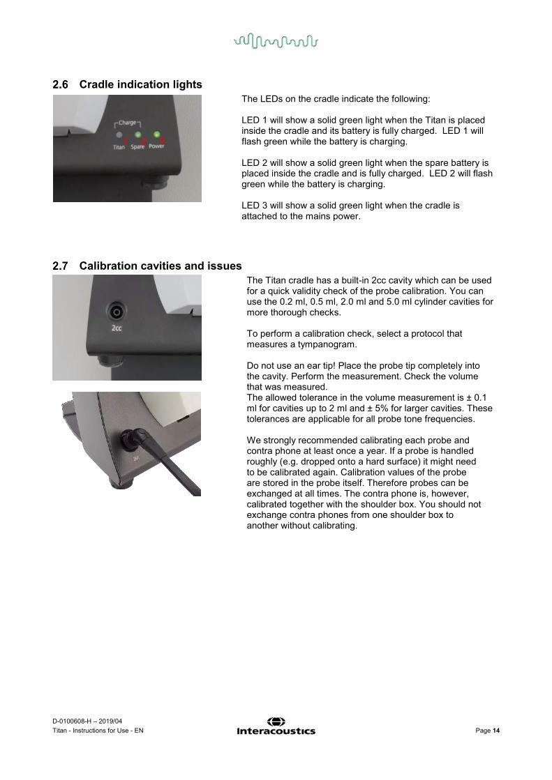
Cradle indication lights The LEDs on the cradle indicate the following:
LED 1 will show a solid green light when the Titan is placed inside the cradle and its battery is fully charged. LED 1 will flash green while the battery is charging. LED 2 will show a solid green light when the spare battery is placed inside the cradle and is fully charged. LED 2 will flash green while the battery is charging. LED 3 will show a solid green light when the cradle is attached to the mains power.
Calibration cavities and issues The Titan cradle has a built-in 2cc cavity which can be used
for a quick validity check of the probe calibration. You can use the 0.2 ml, 0.5 ml, 2.0 ml and 5.0 ml cylinder cavities for more thorough checks. To perform a calibration check, select a protocol that measures a tympanogram. Do not use an ear tip! Place the probe tip completely into the cavity. Perform the measurement. Check the volume that was measured.
The allowed tolerance in the volume measurement is ± 0.1 ml for cavities up to 2 ml and ± 5% for larger cavities. These tolerances are applicable for all probe tone frequencies. We strongly recommended calibrating each probe and contra phone at least once a year. If a probe is handled roughly (e.g. dropped onto a hard surface) it might need to be calibrated again. Calibration values of the probe are stored in the probe itself. Therefore probes can be exchanged at all times. The contra phone is, however, calibrated together with the shoulder box. You should not exchange contra phones from one shoulder box to another without calibrating.
1 2 3

D-0100608-H – 2019/04 Titan - Instructions for Use - EN Page 15
Installing the Sanibel MPT-II thermal printer
2.8.1 Battery pack insertion and charging
Insert battery as shown. Connect the power charger to the outlet on the right hand side of the printer. The blue light on the top of the printer will indicate charging is occurring.
2.8.2 Installing Paper in the Thermal Printer
Open the lid by pushing on the sides.
Place the paper roll in the paper holder with its unfastened end to the front of the printer
Close the lid of the paper holder.
2.8.3 Turning the printer on and off
Push POWER BUTTON for two seconds to power ON or OFF. One short beep will be heard at power ON, two short beeps at power OFF. The Green Power Indicator will be lit if printer is powered by battery. Refer to the Sanibel MPT-II Printer User Manual for more information about printer use.

D-0100608-H – 2019/04 Titan - Instructions for Use - EN Page 16
2.8.4 Connecting the printer to the Titan via cable
Connect the RS-232 (6-pin mini-DIN) cable to the outlet on the left hand side of the printer and the RJ12 plug to the Titan cradle.
2.8.5 Connecting the wireless printer to the Titan Pairing the wireless printer to the Titan is necessary before printing is possible. Follow these instructions to pair the printer:
1. Turn the printer on by holding down the power button for 2 seconds. 2. On the Titan handheld unit, go to Protocol | My Titan | Titan… and set Bluetooth Connection to
Printer. Change the option by pressing the R or L key. 3. Press Back and then go to My Titan | Printer and press Search. 4. Let the instrument search for Bluetooth devices. This may take up to 1 minute. 5. A device called MPT-II should appear in the list of devices. 6. Press Select to finish pairing.
If you want to print out measured results on a wirelessly connected thermal printer it is recommended to switch on the printer before doing the measurements. This will allow the printer enough time to connect and be ready for printing when measurements are completed.
D-0100608-H – 2019/04 Titan - Instructions for Use - EN Page 17
Installing Titan and its battery
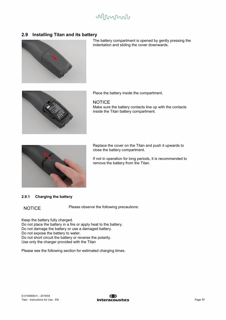
The battery compartment is opened by gently pressing the indentation and sliding the cover downwards.
Place the battery inside the compartment. NOTICE Make sure the battery contacts line up with the contacts inside the Titan battery compartment.
Replace the cover on the Titan and push it upwards to close the battery compartment. If not in operation for long periods, it is recommended to remove the battery from the Titan.
2.9.1 Charging the battery NOTICE
Please observe the following precautions:
Keep the battery fully charged. Do not place the battery in a fire or apply heat to the battery. Do not damage the battery or use a damaged battery. Do not expose the battery to water. Do not short circuit the battery or reverse the polarity. Use only the charger provided with the Titan Please see the following section for estimated charging times.

D-0100608-H – 2019/04 Titan - Instructions for Use - EN Page 18
2.9.2 Battery Lifetime and Charging Time When fully charged, the Titan battery will last for a full day of testing under normal test conditions when the default power save and power off is enabled. Typically, the Titan can perform the following number of continuous tests for the various modules: The figures below have been calculated taking into consideration an average test time of 1 minute per test for IMP, DPOAE and TEOAE. A test time of 3 minutes has been used to calculate the number of tests that can be performed in ABRIS.
Module Test (average test times explained above) Number of tests
IMP440
Tymp, + Reflexes ipsi and contra
200+
DPOAE440
DP-Gram Detailed
200+
ABRIS440
ABR infant screening
75
TEOAE440
TEOAE test
200+
The Titan battery automatically starts charging when placed in the cradle if this is connected to mains power. Keeping the spare battery in the cradle charging compartment means you will always have fully charged spare battery. Interacoustics provides a medically approved mains power supply to be used for charging the Titan. A DC USB adaptor can be used to connect the Titan to the medically approved mains power supply when the cradle is not in use. Then the battery in Titan is charged within the same time frame as if it was placed in the cradle. The Titan battery can also be charged via connection to a PC with a USB cable provided. Testing can be performed while the Titan battery is charging. The following table gives an estimate of the charging time (ct) in hours for the battery. Be aware that negative numbers mean that the battery is discharging. Charge times for the spare battery in the cradle and the battery in the Titan while placed in the cradle are the same.
ct through cradle up to 80%
ct through USB (PC) up to 80%
ct through cradle up to 100%
ct through USB (PC) up to 100%
Off 1,5 3,8 2,3 5,7 On (not testing) 2,8 -32 4,1 -47

D-0100608-H – 2019/04 Titan - Instructions for Use - EN Page 19
Changing probes and extension cords on the Titan The Titan probe can be connected in four ways to the device:
1) directly to the Titan (IMP440/WBT440 only). 2) using the short extension cable (IMP440/WBT440/DPOAE440/TEOAE440). 3) using the long clinical extension cable with the shoulder box (for OAE & IMP). 4) using the preamplifier cable (for OAE/IMP & ABRIS).
Note that the length of the tubing influences the pump speed in the IMP440 module. When the probe is directly connected to the Titan, pump speeds are about 60% higher than when it is connected via the long clinical extension cable (shoulder box) or preamplifier cable. For the most accurate measurements it is recommended to use probe while connected via the long clinical extension cable (shoulder box) or preamplifier cable.
Ensure that the Titan is switched off before attaching or detaching the probe, short or long clinical extension cable (shoulder box) or preamplifier cable from the Titan.
To release the probe or one of the extension cables from the Titan, press the button at the back of the Titan and pull the probe or extension cord out while holding onto the base of the probe or extension cable. Do not pull directly on the cord of the extension cable as this can damage the tubing connections! Do not pull directly on the probe tip as this may cause it to break!
Connect the extension cord or probe to the Titan by lining up the red triangles and pushing the probe or extension cable into the connection plate.

D-0100608-H – 2019/04 Titan - Instructions for Use - EN Page 20
Connecting transducers to the shoulder box and preamplifier You can only perform contralateral stimulation during impedance reflex measurements when the long clinical extension cable (shoulder box) or preamplifier cable is connected to the Titan.
When using the long clinical extension cable (shoulder box) for IMP/OAE, plug the jack of the contralateral headphone, insert phone or CIR55 into the shoulder box where it is labeled “Phones Contra”.
When using the preamplifier cable, all transducers (contra headphones, TDH39, Insert E-A-RTONE 3A etc), except for the probe, are connected via the Omnetics port (1) beside the probe connection plate (2).
Placing and using the Long Clinical Extension Cable (Shoulder Box) or preamplifier cable
The long clinical extension cable with the small shoulder box can be used for impedance and OAE measurements. The preamplifier cable is required for ABRIS testing and can also be used with all other modules. Use the clip on the back of the long clinical extension cable (shoulder box) to attach it to the clothing of the patient. For most patients it may be suitable to attach the shoulder box to the collar of their shirt/blouse. For the preamplifier cable it may be more suitable to attach it to the strap which can then be placed around the neck of the parent who is holding the patient.
The shoulder box button (1) can be used for operating the Titan during and in between testing. During PC controlled mode testing, the shoulder box button (1) can be used to START or STOP testing when a seal is maintained in the ear. In between testing, when the probe is out of the ear, pressing the button will change the selected ear from right to left and vice versa.
The button (2) on the preamplifier can be used to START or STOP a test.
1 2
2

D-0100608-H – 2019/04 Titan - Instructions for Use - EN Page 21
Placing the montage-indication stickers on the preamplifier A sheet containing Montage-Indication stickers has been enclosed to provide assistance to the user for correct placement of the electrodes and cables. Each sheet contains two stickers; the top one showing the mastoid montage setup and the bottom one showing the nape montage setup.
Remove the required sticker from the sheet and attach inside the recess on the back of the preamplifier.

D-0100608-H – 2019/04 Titan - Instructions for Use - EN Page 22
Use of the E-A-RTONE ABR transducer with ear tips, foam inserts or EarCups (ABRIS440 only)
There are two versions of the E-A-RTONE ABR transducer for use with the ABRIS440 module. The ID E-A-RTONE ABR transducer is for use with the 3.5mm or 4.0mm infant ear tips, foam insert ear tips or the Titan probe ear tips via an adaptor. The transducer is labeled “Calibrated for use with inserts”.
The ID E-A-RTONE EarCup transducer is for use with EarCups via an adaptor. The transducer is labeled “Calibrated for use with EarCups”.
Even though the transducers appear to be the same, ensure you are using the transducer with the disposable it is calibrated for. Misuse may lead to incorrect results due to differences in the calibration.

D-0100608-H – 2019/04 Titan - Instructions for Use - EN Page 23
Use of the IP30 ABR transducer with ear tips, foam inserts or EarCups (ABRIS440 only)
There are two versions of the IP30 ABR transducer for use with the ABRIS440 module. The IP30 ABR transducer is for use with the 3.5mm or 4.0mm infant ear tips, foam insert ear tips or the Titan
probe ear tips via an adaptor. The transducer is labeled “Calibrated for use with inserts”.
The IP30 Earcup transducer is for use with EarCups via an adaptor. The transducer is labeled “Calibrated for use with EarCups”.
Even though the transducers appear to be the same, ensure you are using the transducer with the disposable it is calibrated for. Misuse may lead to incorrect results due to differences in the calibration.
Safety Precautions to take when connecting the Titan NOTICE Please note that if connections are made to standard equipment like printers and networks, special precautions must be taken in order to maintain medical safety. Please follow instructions below. Fig 1. Titan used with the medically approved power supply and DC USB adaptor.
Mains outletMedical power supply
Titan alone

D-0100608-H – 2019/04 Titan - Instructions for Use - EN Page 24
Fig. 2. Titan used with the Cradle and the medically approved power supply
Fig. 3. Titan used with the Cradle, medically approved power supply and wireless printer.

D-0100608-H – 2019/04 Titan - Instructions for Use - EN Page 25
Fig 4. Titan used with the Cradle, medically approved power supply and a wired printer powered by a battery.

D-0100608-H – 2019/04 Titan - Instructions for Use - EN Page 26
Fig. 5. Titan used with the Cradle, medically approved power supply and a wireless connection to a PC.

D-0100608-H – 2019/04 Titan - Instructions for Use - EN Page 27
Fig. 6. Titan used with the Cradle, medically approved safety transformer and a wired connection to a PC. Not suitable for ABRIS440 use as patient safety is not maintained – refer Fig. 8.

D-0100608-H – 2019/04 Titan - Instructions for Use - EN Page 28
Fig. 7. Titan used with the Cradle, medically approved safety transformer, wired connection to a PC, and a wireless connection to a printer. Not suitable for ABRIS440 use as patient safety is not maintained – refer Fig. 8.
D-0100608-H – 2019/04 Titan - Instructions for Use - EN Page 29
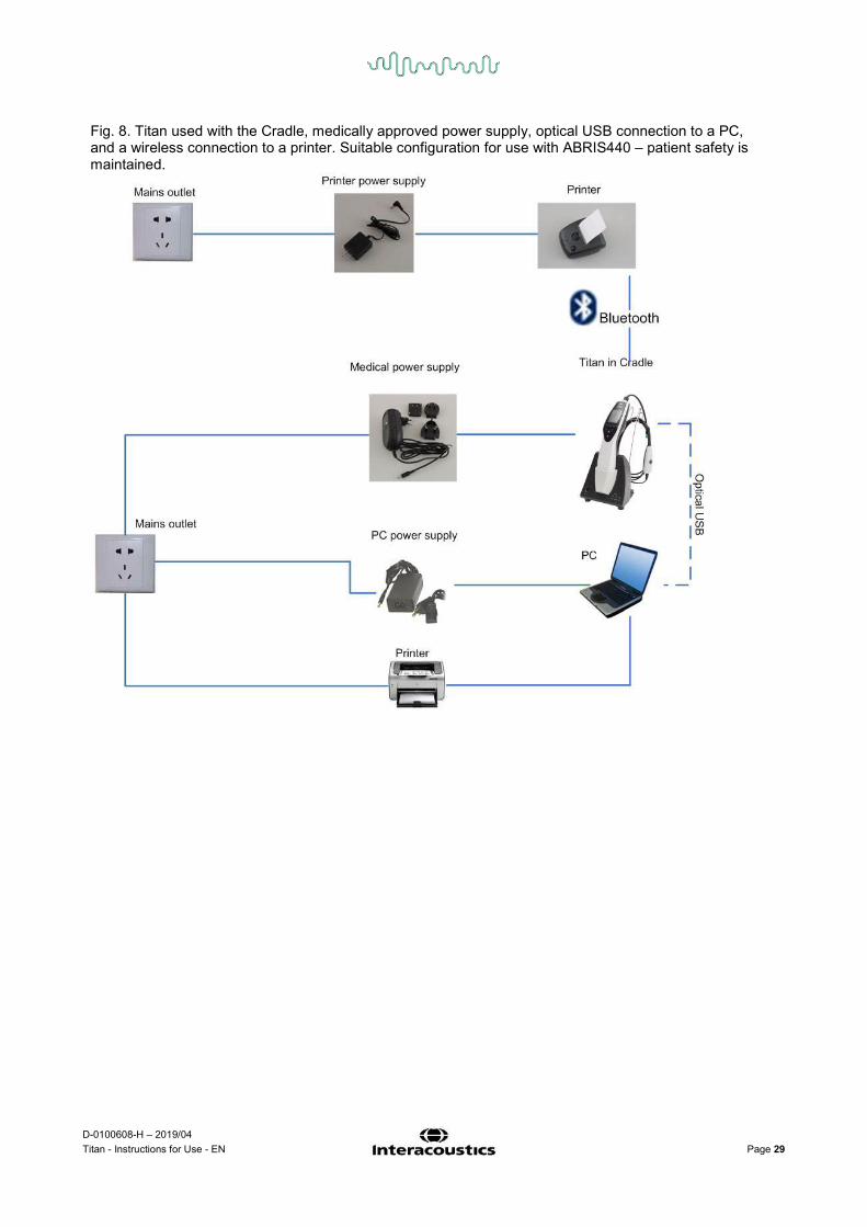
Fig. 8. Titan used with the Cradle, medically approved power supply, optical USB connection to a PC, and a wireless connection to a printer. Suitable configuration for use with ABRIS440 – patient safety is maintained.

D-0100608-H – 2019/04 Titan - Instructions for Use - EN Page 30
Software installation To know before you Start Installation You must have administrative rights to the computer on which you are installing the Titan Suite. Important note on the use of Normative Data You are about to install the Titan Suite software. Some parts of the software have normative data available that can be displayed and compared to recordings made. If it is preferred not to display normative data, these can be deselected in the test protocols in question or new alternative protocols without normative data can be created and used. Interacoustics claims no diagnostic consequence of degree of fit between the recorded results and whatever normative data examples the operator chooses to bring forward for comparison. Further information about the normative data can be obtained from the Titan Additional Information Manual and from Interacoustics. NOTICE
1. DO NOT connect the Titan hardware to the computer before the software has been installed! 2. Interacoustics will not make any guarantee to the functionality of the system if any other software is
installed, with exception of the Interacoustics OtoAccess® or Noah 4.0 or higher. PC minimum requirements
• 2 GHz Dual Core CPU or better (Intel recommended) • 1GB RAM or more (4GB recommended) • Hard drive with min 10 GB free space (Solid State Drive (SSD) recommended) • Minimum display resolution of 1024x768 pixels (1280x1024 or higher recommended) • DirectX 9.0c compatible graphics (Intel/NVidia recommended) • One or more USB ports, version 1.1 or higher • DVD-ROM drive
Supported operating systems
• Microsoft Windows® 7 32-bit and 64-bit • Microsoft Windows® 8 32-bit and 64-bit • Microsoft Windows® 10 32-bit and 64-bit
Windows® is a registered trademark of Microsoft Corporation in the United States and other countries. Important: make sure you have the latest service packs and critical updates installed for the version of Windows® that you are running. What you will need:
1. Titan Suite Installation DVD. 2. USB Cable. 3. Titan Hardware.
To use the software in conjunction with a database (e.g. Noah 4 or OtoAccess®), make sure the database is installed prior to the Titan Suite installation. Follow the manufacturer’s installation instructions provided to install the relevant database. Note that if you are using AuditBase System 5 you must ensure to launch this office system prior to this installation of the Titan Suite.

D-0100608-H – 2019/04 Titan - Instructions for Use - EN Page 31
Software installation on Windows® 7, Windows® 8 and Windows® 10 Insert the installation DVD and follow the steps below to install the Titan Suite software. If the installation procedure does not start automatically, click “Start”, then go to “My Computer” and double click the DVD/CD-RW drive to view the contents of the installation DVD. Double click the “setup.exe” file to initiate the installation.
1. Wait for the dialog shown below to appear, agree to the license terms and conditions, then click “Install”.
2. Follow the onscreen Titan Installer instructions until the installation has been completed. Click on “Close”. The software is now installed and ready to use.
During installation, Windows® may: a) Ask if you want to allow changes to the computer. Click Yes if this happens b) Ask to download and install a new Windows Feature (e.g., .NET Framework 3.5). Download and
install new features to ensure that the Titan Suite software works as intended c) Warn you that Windows cannot verify the publisher of this driver software. Install the driver
software anyway to ensure the Titan works as intended. If not installed, the Titan will not be detected by the computer when connected via USB
D-0100608-H – 2019/04 Titan - Instructions for Use - EN Page 32
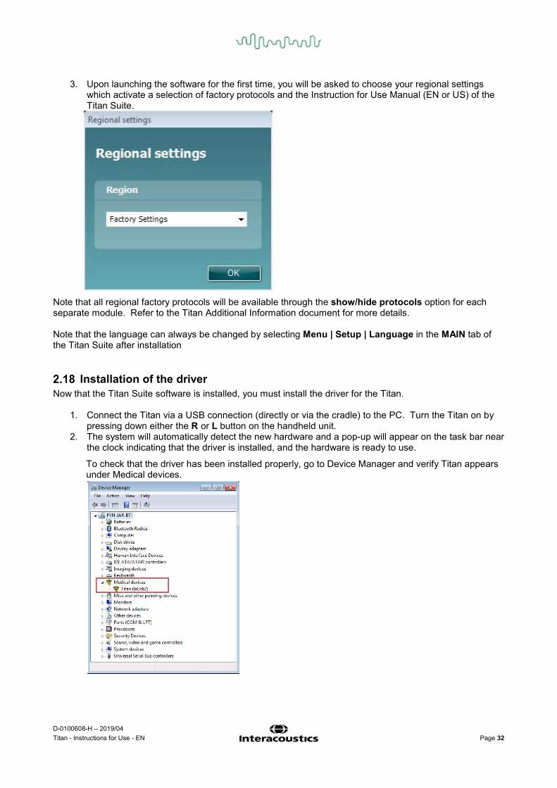
3. Upon launching the software for the first time, you will be asked to choose your regional settings which activate a selection of factory protocols and the Instruction for Use Manual (EN or US) of the Titan Suite.
Note that all regional factory protocols will be available through the show/hide protocols option for each separate module. Refer to the Titan Additional Information document for more details. Note that the language can always be changed by selecting Menu | Setup | Language in the MAIN tab of the Titan Suite after installation
Installation of the driver Now that the Titan Suite software is installed, you must install the driver for the Titan.
1. Connect the Titan via a USB connection (directly or via the cradle) to the PC. Turn the Titan on by pressing down either the R or L button on the handheld unit.
2. The system will automatically detect the new hardware and a pop-up will appear on the task bar near the clock indicating that the driver is installed, and the hardware is ready to use.
To check that the driver has been installed properly, go to Device Manager and verify Titan appears under Medical devices.

D-0100608-H – 2019/04 Titan - Instructions for Use - EN Page 33
Standalone installation of Titan Suite If you do not want to run the Titan Suite through Noah 4 or OtoAccess® you can make a shortcut on the desktop to directly launch the Titan Suite as a standalone module.
Go to Start | Programs | Interacoustics | Titan Suite. Right click on Titan Suite and select Send To | Desktop (create shortcut). A shortcut for the Titan Suite will now appear on your desktop.
Note: Saving sessions in standalone mode will not link the measurements to a specific patient and cannot be transferred to a patient in the database later.
License When you receive the Titan product it already contains the license including the software modules you have ordered. If you would like to add another module that is available in the Titan Suite, please contact your dealer for a license.
Creating a Bluetooth connection for PC controlled measurements If you want to use a Bluetooth connection to carry out PC controlled measurements with the Titan, you have to assure that Bluetooth is installed on your PC. If Windows® asks for a passkey during the installation process: The default passkey is 1234. For further information about setting up a Bluetooth connection, please refer to the Bluetooth Installation Quick Guides.

D-0100608-H – 2019/04 Titan - Instructions for Use - EN Page 34
Bluetooth installation (Windows® 7) Turn on the Titan Handheld Unit (HHU) and your Windows® 7 PC/laptop:
1. Select Protocol | My Titan |Titan and change Bluetooth Connection to PC, by pressing the R or L button.
2. From the task bar, left click on the Bluetooth Icon and select Add Device.
3. When the screen below appears, select the Titan for pairing and then click Next. Enter the pairing code (1234) and click Next.

D-0100608-H – 2019/04 Titan - Instructions for Use - EN Page 35
4. The Titan and your PC are now connected via Bluetooth. Click Close.
5. To confirm the Bluetooth pairing, Start up the Titan Suite from OtoAccess®, Noah 4 or in Standalone mode (see the Titan Additional Information Manual for further instructions). Ensure that the Titan is still switched on.
6. Allow the Bluetooth device to search for the Titan. After a short while, your Titan with a corresponding identification number will appear in the window below.
7. Click on “Titan xxxxxx” and wait a few seconds to allow it to connect.
8. On connection, the Suite will finish launching and the Titan HHU screen will show “PC-controlled”
Now the Titan can be operated from PC in the same way as if it was connected via a USB cable. Note: If the Titan will not connect correctly and your PC has its manufacturer’s Bluetooth Driver installed, you may need to uninstall this and then try re-pairing the Titan with your PC.

D-0100608-H – 2019/04 Titan - Instructions for Use - EN Page 36
Bluetooth installation (Windows® 8 & 10) Turn on the Titan Handheld Unit (HHU) and your Windows® 8 or 10 PC/laptop:
1. Select Protocol | My Titan |Titan and change Bluetooth Connection to PC, by pressing the R or L button.
2. From the task bar, right click on the Bluetooth Icon and select Add a Bluetooth Device.
3. When the screen below appears, select the Titan for pairing and then click Pair. Enter the pairing code (1234) and click Next.

D-0100608-H – 2019/04 Titan - Instructions for Use - EN Page 37
4. The Titan is now paired to your PC via Bluetooth. Close the dialog box.
5. To confirm the Bluetooth pairing, Start up the Titan Suite from OtoAccess®, Noah or in Standalone mode (see the Titan Additional Information Manual for further instructions). Ensure that the Titan is still switched on.
6. Allow the Bluetooth device to search for the Titan. After a short while, your Titan with a corresponding identification number will appear in the window below.
7. Click on “Titan xxxxxx” and wait a few seconds to allow it to connect.
8. On connection, the Suite will finish launching and the Titan HHU screen will show “PC-controlled”. Now the Titan can be operated from PC in the same way as if it was connected via a USB cable.
Note: If the Titan will not connect correctly and your PC has its manufacturer’s Bluetooth Driver installed, you may need to uninstall this and then try re-pairing the Titan with your PC.

D-0100608-H – 2019/04 Titan - Instructions for Use - EN Page 38

D-0100608-H – 2019/04 Titan - Instructions for Use - EN Page 39
3 Operating instructions The instrument is switched on by pressing either the R or L button on the handheld unit. When operating the instrument, please observe the following general precautions:
1. Use this device only as described in this manual. 2. Use only the disposable Sanibel ear tips designed for use with this instrument. 3. Always use a new ear tip for each patient to avoid cross-contamination. The ear tip is not designed
for reuse. 4. Never insert the probe tip into the ear canal without affixing an ear tip as omission may damage the
patient’s ear canal. 5. Keep the box of ear tips outside the reach of the patient. 6. Be sure to insert the probe tip in a way which will assure an airtight fit without causing any harm to
the patient. Use of a correct and clean ear tip is mandatory. 7. Be sure to use only stimulation intensities acceptable to the patient. 8. When presenting contralateral stimuli using the insert phones – do not insert the phones or in any
way try to conduct measurements, without a correct insert ear tip in place. 9. When presenting contralateral stimuli using headphones – do not try to conduct measurements
without the MX41 cushion in place. 10. It is recommended to conduct a probe test at the beginning of each day to ensure that the probe
and/or cable is functioning correctly for TEOAE measurements. 11. Clean the probe tip regularly to ensure wax or other debris stuck in the probe tip does not affect the
measurement.
12. Clean the headphone cushion regularly using a recognized disinfectant. 13. Contraindications to testing include recent stapedectomy or middle ear surgery, a discharging ear,
acute external auditory canal trauma, discomfort (e.g, severe otitis externa) or occlusion of the external auditory canal. Testing should not be performed on patients with such symptoms without a medical doctor’s approval.
14. The presence of tinnitus, hyperacusis or other sensitivity to loud sounds may contraindicate testing when high intensity stimuli are used.
15. When the Titan is used clinically with the handheld instrument placed in the cradle, use a 50% duty cycle, meaning that a period of continuous testing must be followed by a similar period where the device is not used.
16. The EEG level can be affected if the Titan is charging in the cradle during testing. It is advised not to charge the Titan during ABRIS testing.
NOTICE
1. Careful handling of the instrument whenever in contact with a patient should be given high priority. Calm and stable positioning while testing is preferred for optimal accuracy
2. The Titan should be operated in a quiet environment, so that measurements are not influenced by outside acoustic noises. This may be determined by an appropriately skilled person trained in acoustics. ISO 8253 Section 11, defines a quiet room for audiometric hearing testing in its guideline.
3. It is recommended that the instrument be operated within an ambient temperature range of 15°C / 59°F – 35°C / 95°F
4. The headphone and insert phone are calibrated to the shoulder box of this instrument – introducing transducers from other equipment requires a re-calibration.
5. Never clean the transducer housing with water or insert non-specified instruments into the transducer

D-0100608-H – 2019/04 Titan - Instructions for Use - EN Page 40
6. Do not drop and avoid other undue impact to this device. If the instrument is dropped or otherwise damaged, return it to the manufacturer for repair and/or calibration. Do not use the instrument if any damage is suspected.
7. Although the instrument fulfils the relevant EMC requirements, precautions should be taken to avoid unnecessary exposure to electromagnetic fields, e.g. from mobile phones etc. If the device is used adjacent to other equipment, caution must be taken to observe that no mutual disturbance appears.
Handling and selection of ear tips
When using the Titan probe and CIR55 contra phone, Sanibel ear tips must be used. The Sanibel ear tips are single use only and should not be reused. Reuse of ear tips can lead to the spread of infection from patient to patient. The probe (and CIR55 contra phone) must be fitted with an ear tip of a suitable type and size before testing. Your choice will depend on the size and shape of the ear canal and ear. Your choice may also depend on personal preference and the way you perform your test.
When performing a quick impedance screening test you may choose an umbrella shaped ear tip. Umbrella ear tips seal the ear canal without the probe tip going into the ear canal. Press the ear tip firmly into the ear canal in such a way that a seal remains during the complete test.
For more stable testing, we recommend using an extension cord with a mushroom shaped ear tip. Make sure that this ear tip inserts completely into the ear canal. Mushroom shaped ear tips allow you to test ‘hands free’ from the Titan. This reduces the chance of contact noise disturbing the measurement.
Refer to the “Selecting the Correct Ear Tip” Quick Guide for an overview of ear tip sizes and selection.
Switching the Titan on and off
Switch the Titan on by pressing either the or button.
To switch the Titan off, hold down both the and button at the same time for 1 second. NOTICE The Titan takes approximately 2 seconds to boot up. Allow the unit to warm up for 1 minute before use.

D-0100608-H – 2019/04 Titan - Instructions for Use - EN Page 41
Probe status The probe status is indicated by the color of the light at the end of the extension cord, on the shoulder box or on the probe status bar in the software. Below, the colors and their meanings are explained:
Color Status Red Right ear is selected. Probe is out of the ear. Blue Left ear is selected. Probe is out of the ear. Green Probe is in the ear and a seal is maintained. Yellow Probe is in the ear and is blocked, leaking or too noisy. White The probe has just been attached. Probe status is unknown. If the probe light
stays white in any other situation the Titan may need to be switched off and back on again to regain proper probe status.
Green changing to red/blue
The current test has been completed.
No light Titan is no longer monitoring the probe status, or the probe is in a big cavity e.g when using Forced Start (for impedance only).
Titan handheld operation panel
Symbol Function
F1 – F3 The F1 – F3 keys allow selection of various options
indicated on the Titan display screen above each individual function key, e.g., “Print”, “Save” and “Delete”.
F4 – F5 The R and L buttons allow ear selection. Hold down F4 (R) and F5 (L) at the same time to turn off the Titan.
F6 – F7 The Up and Down buttons (F6 and F7) navigate through lists, menus etc. These buttons also allow you to scroll through the different tests which are indicated in the selected screen.
D-0100608-H – 2019/04 Titan - Instructions for Use - EN Page 42
Operating Titan in handheld mode
3.5.1 Startup The Titan will always start on the previously used protocol Test screen, ready to start a measurement. When switching on the Titan in handheld mode after disconnecting from a PC, it will start in the Select Protocol screen and you will have to select which protocol to use next.
3.5.2 Battery When the Titan battery’s power capacity becomes low, the first indication you will see is the battery symbol in the top right hand corner of the hand held unit change color. When the battery’s power level becomes too low that measurements can no longer be performed, a warning will appear on screen, the measurement will be stopped and all recorded data will be stored. You will have to turn off the handheld unit and change battery or place the Titan in the cradle to be able to continue testing. Upon restarting the Titan, the previously measured data will be recovered and you can continue with your measurements without retesting.
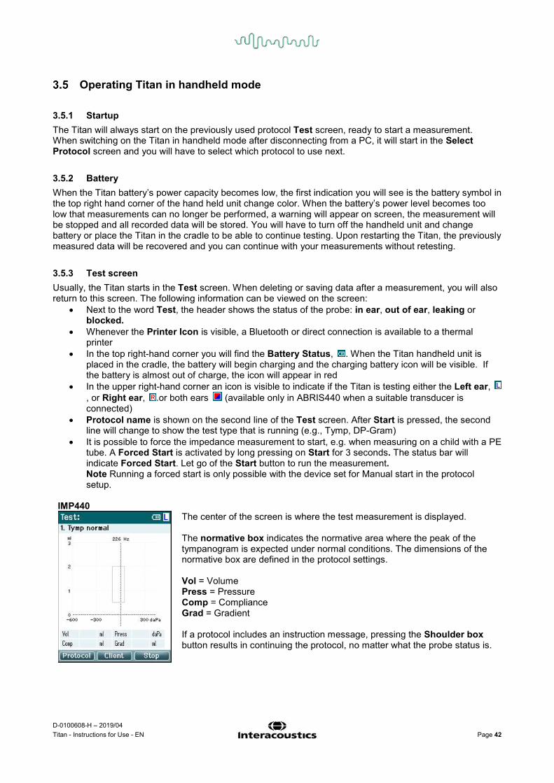
3.5.3 Test screen Usually, the Titan starts in the Test screen. When deleting or saving data after a measurement, you will also return to this screen. The following information can be viewed on the screen:
• Next to the word Test, the header shows the status of the probe: in ear, out of ear, leaking or blocked.
• Whenever the Printer Icon is visible, a Bluetooth or direct connection is available to a thermal printer
• In the top right-hand corner you will find the Battery Status, . When the Titan handheld unit is placed in the cradle, the battery will begin charging and the charging battery icon will be visible. If the battery is almost out of charge, the icon will appear in red
• In the upper right-hand corner an icon is visible to indicate if the Titan is testing either the Left ear, , or Right ear, .or both ears (available only in ABRIS440 when a suitable transducer is connected)
• Protocol name is shown on the second line of the Test screen. After Start is pressed, the second line will change to show the test type that is running (e.g., Tymp, DP-Gram)
• It is possible to force the impedance measurement to start, e.g. when measuring on a child with a PE tube. A Forced Start is activated by long pressing on Start for 3 seconds. The status bar will indicate Forced Start. Let go of the Start button to run the measurement. Note Running a forced start is only possible with the device set for Manual start in the protocol setup.
IMP440
The center of the screen is where the test measurement is displayed. The normative box indicates the normative area where the peak of the tympanogram is expected under normal conditions. The dimensions of the normative box are defined in the protocol settings. Vol = Volume Press = Pressure Comp = Compliance Grad = Gradient If a protocol includes an instruction message, pressing the Shoulder box button results in continuing the protocol, no matter what the probe status is.

D-0100608-H – 2019/04 Titan - Instructions for Use - EN Page 43
ABRIS440
The circles on the baby’s head indicate the electrode montage for the test and the status of the electrode impedance; green = acceptable, amber = poor. The selected transducer name is displayed next to the baby’s head.
Below the test time, the impedance value for each of the three electrodes (white, red, blue) is displayed. The three buttons on the bottom row of the screen correspond with the top three function buttons on the hand held unit During testing: The EEG bar is displayed and shows the EEG peak values. The black bar represents the EEG peak level above which a measurement will be rejected (displayed in amber).
If the test is started when the electrode impedance indicators are amber (poor), the impedance is not ideal warning window will appear. The user must confirm whether they wish to proceed with testing if impedance values are poor. Poor impedance can lead to longer test times and noisier recordings.
DPOAE440
The center of the screen is where the test measurement is displayed. The display will differ depending on the view selected in the protocol: Bar view or Graph view.

D-0100608-H – 2019/04 Titan - Instructions for Use - EN Page 44
TEOAE440
The center of the screen is where the test measurement is displayed. The display will differ depending on the view selected in the protocol: Basic view or Advanced view.
Operating from this screen: - Top left button on the hand held unit will take you into the Protocol screen from where you can
select a different protocol or go into Titan Setup - Top middle button will bring you to the View Client screen from where client data can be viewed
and changed and earlier sessions can be reviewed and/or printed. During testing, this button allows you to Pause the test (excluding IMP440)
- Top right button will either start the test or stop the test. Done! will appear in the top green panel when the test is complete
- Right and Left buttons on the hand held unit will respectively select the right or left ear for testing. To reactivate binaural testing, after the right or left ear button is pressed, return to the Protocol screen and reselect the protocol (ABRIS440 only)
- If data for one or both ears has been collected, and Done! appears in the top green panel, the Up and Down buttons allow you to scroll through the collected measurements or tables
- Shoulder box button allows you to start and stop testing when the probe is in the ear or change ears when the probe is out of the ear
3.5.4 Done screen The Titan will automatically go to the Done! screen when it has finished testing a protocol. From here, measurements from both ears can be reviewed, printed and/or saved.

D-0100608-H – 2019/04 Titan - Instructions for Use - EN Page 45
Operating from this screen: - Top left button will result in printing the test results of the left and right ears. Note that this will only
occur if a printer is connected to the Titan via Bluetooth or wired to the Titan cradle with the hand held unit sitting in the cradle
- Top middle button will bring you to the Select Client & Save Screen from where client data can be saved. The Titan is made for intuitive use and after saving data Titan prepares itself for a new measurement by clearing its working memory and returning to the Test screen. You can either choose to print data before you save it or retrieve saved measurements from the session list and print later
- Top right button displays a pop up a message asking, “Delete current or both ears?” when pressed. The Top left button will cancel the process. The Top middle button will delete the data of the currently selected ear and bring you back to the Test screen. The Top right button will delete data on both ears and bring you back to the Test screen
- Right and Left buttons will respectively select the right or left ear for testing and will bring you back to the Test screen. If data exists for the test ear, a pop-up will appear asking “Overwrite existing data?”. The Top left and Top right buttons allow yes and no answers respectively
- Right and Left buttons will respectively select the right or left ear for testing and will bring you back to the Test screen. Existing data from the chosen ear will only be deleted after pressing “Yes” to “Overwrite existing data” (except IMP440). If the probe is detected to be in the ear with a proper seal and the protocol has autostart enabled, a new measurement will automatically overwrite existing data (IMP440 only)
- Up and Down buttons allow you to scroll through the different test results. When viewing the first or last test of an ear, pressing Up or Down respectively will take you to the test results of the other ear.
- Shoulder box button will result in bringing you back to the Test screen
3.5.5 Select Client & Save From this screen you can either save data to an existing client that has been uploaded to the Titan from your database or save data to a new client name. New clients will always get the name “ID #”, where # stands for the next available unique client number. A maximum of 250 clients should be stored on the handheld unit.
Operating from this screen: - Top left button will bring you back to the Done! screen without saving
and without deleting data - Top middle allows you to edit the client name before saving - Top right button will save the data to the selected client. After saving
the current measurement, all data is deleted and the Titan returns in the Test screen, ready for testing
- Right and Left buttons allow you to jump from the top or bottom of the client list respectively
- Up and Down buttons allow you to scroll up and down through the client list
- Shoulder box button has no function

D-0100608-H – 2019/04 Titan - Instructions for Use - EN Page 46
3.5.6 Edit New Screen This screen allows you to input the client’s details before saving the measurement.
Operating from this screen: - Top left button saves the client’s details and takes you back to the
Select Client & Save screen - Top middle button will select the highlighted character and input it into
the selected field where the cursor appears. Backspace is found as an arrow in the top right hand corner. Adding a space is achieved by moving the course to the bar below the letters and hitting Select
- Top right button will tab to the next field available for editing - Right and Left buttons allow you to move from left to right on the
keyboard panel - Up and Down buttons allow you to move up and down on the keyboard
panel. When editing the birth date the Up and Down buttons will change the numerical value
- Shoulder box button has no function while in this screen
3.5.7 View Clients Screen This screen shows a list of clients. Some of the clients may have been uploaded from your database to Titan hand held unit. When one or more sessions are stored on the Titan, the box in front of the client’s name is filled. If there is no session stored yet, the box is empty.
Operating from this screen: - Top left button takes you back to the Test screen - Top middle button takes you to the View Details screen where the
client details are shown - Top right button will take you to the View Sessions screen from where
the available sessions of the selected client can be reviewed and printed
- Right and Left buttons allow you to jump from the top or bottom of the client list respectively
- Up and Down buttons allow you to scroll up and down through the client list
- Shoulder box button has no function while in this screen

D-0100608-H – 2019/04 Titan - Instructions for Use - EN Page 47
3.5.8 View Details Screen
This screen shows the details entered for the selected client. From here you can either use the Top left button to go back to the View Client screen or use the Top middle button to edit the client details in the Edit Details screen
3.5.9 Edit Details Screen This screen shows the client ID, First Name, Last Name and Birth Date. On entering this screen, the First name is selected for editing.
Operating from this screen: - Top left button takes you back to the View Details screen - Top middle button will select the highlighted character and input it
into the selected field where the cursor appears. Backspace is found as an arrow in the top right hand corner. Adding a space is achieved by moving the course to the bar below the letters and hitting Select
- Top right button will tab to the next field available for editing - Right and Left buttons allow you to move from left to right on the
keyboard panel - Up and Down buttons allow you to move up and down on the
keyboard panel. When editing the birth date the Up and Down buttons will change the numerical value
- Shoulder box button has no function while in this screen
3.5.10 View Sessions Screen For the selected client, this screen shows a list of available saved measurements.
Operating from this screen: - Top left brings you back to the View Client screen - Top middle button will prompt you and ask for confirmation before it
deletes the selected session or all sessions. Note: Press the Back button if you decide you do not want to delete a session/s
- Top right button will show the selected measurement in the View Session screen
- Right and Left buttons allow you to jump from the top to the bottom of the of the session list respectively
- Up and Down buttons allow you to scroll up and down through the session list

D-0100608-H – 2019/04 Titan - Instructions for Use - EN Page 48
3.5.11 View Session Screen In this screen the test recordings of the selected session are shown.
Operating from this screen:
- Top left takes you back to the View Sessions screen - Top middle button will print all. Note that this will only occur if a printer is connected to the Titan via
Bluetooth or wired to the Titan cradle with the hand held unit is sitting in the cradle - Top right button has no function - Right and Left buttons will toggle between the saved recordings for the right or left ear respectively,
if available - Up and Down buttons allow you to scroll through the different tests that are saved in the selected
session - Shoulder box button has no function
3.5.12 Select Protocol Screen From this screen you can either select a protocol for testing or go into the Titan settings.
Operating from this screen: - Top left button takes you back to the Test screen of the same
protocol previously selected or used - Top middle button takes you to the Setup screen - Top right button selects the protocol of your choice and takes you
to the Test screen - Right and Left buttons allow you to jump from the top or bottom of
the protocol list respectively - Up and Down buttons allow you to scroll up and down through the
protocols one at a time - Shoulder box button has no function

D-0100608-H – 2019/04 Titan - Instructions for Use - EN Page 49
3.5.13 Setup Screen From the My Titan screen, the settings concerning the Titan hand held unit can be changed.
Operating from this screen: - Top left button brings you back to the Select Protocol screen - Top middle button has no function - Top right button selects the highlighted setting to be viewed. - Right and Left buttons have no function - Up and Down buttons allow you to move up and down
through the listed items - Shoulder box button has no function Note: If forced saving has been enabled on the hand held unit, this screen is not available.
3.5.14 Language Screen
Use the Right and Left buttons to adjust the language. Available languages are English, German, Spanish, French, Italian, Portuguese, Czech, Russian, Japanese, Chinese and Korean.
3.5.15 Date & Time Screen
Use the Left and Right buttons to jump to the next or previous item. Use the Up and Down buttons to adjust the Date, Date format and Time.

D-0100608-H – 2019/04 Titan - Instructions for Use - EN Page 50
3.5.16 Titan Screen
Use the Up and Down buttons to go to the next or previous item. Use the Right and Left buttons to adjust the settings in:
- Bluetooth can either be connected to a printer, to the PC or turned off
- The Power Save can be set to never or 1, 2, 3, 4 or 5 minutes - The Power Off can be set to never or 1, 2, 3, 4, 5, 6, 7, 8, 9,
10, 15, 20, 30, or 45 minutes and only works in hand held mode
- Height Above Sea Level can be set from 0 to 2500 meters
3.5.17 Printer Screen
Use the Top right button to search for a Bluetooth connection to a printer. When more than one printer is found, use the Up and Down buttons to select the printer of your choice. Press the Top right button to select the printer.
3.5.18 Clinic Info Screen
Use the Left, Right, Up and Down buttons to move the cursor over the keyboard. Press the Top middle button to insert the highlighted character. Press the Top right button to go to the next item. Press the Top left button to save and go back to the Setup screen.
D-0100608-H – 2019/04 Titan - Instructions for Use - EN Page 51
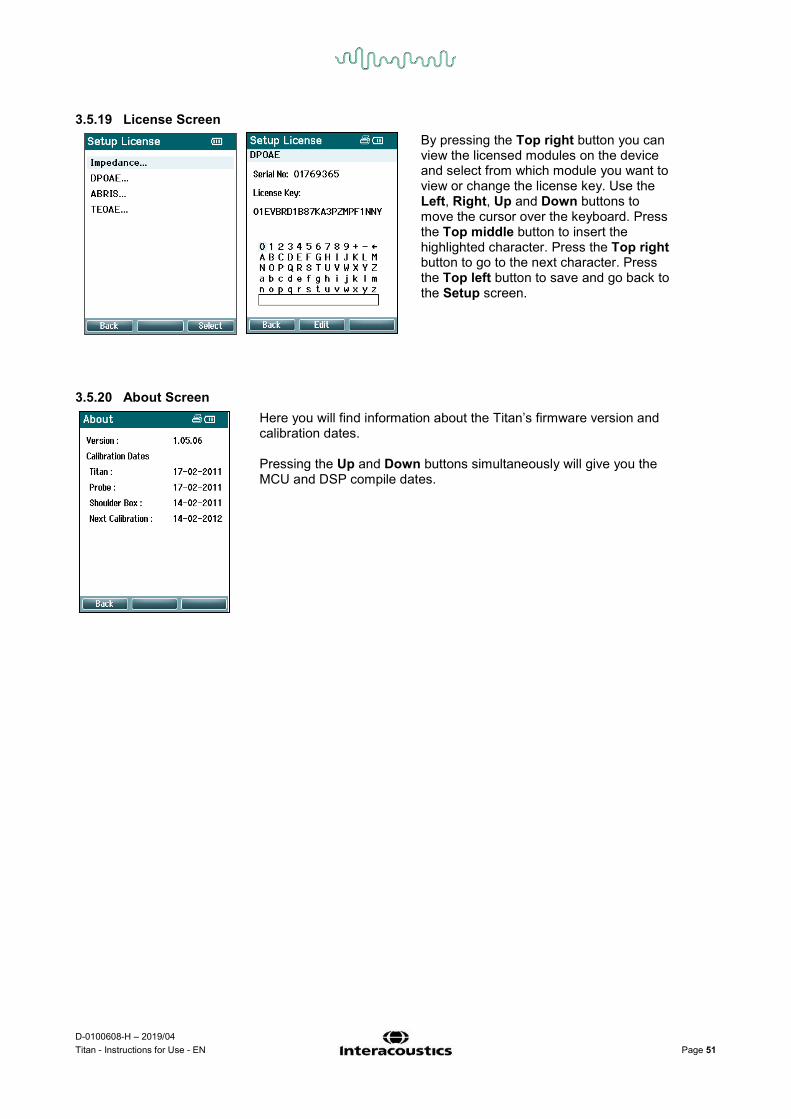
3.5.19 License Screen
By pressing the Top right button you can view the licensed modules on the device and select from which module you want to view or change the license key. Use the Left, Right, Up and Down buttons to move the cursor over the keyboard. Press the Top middle button to insert the highlighted character. Press the Top right button to go to the next character. Press the Top left button to save and go back to the Setup screen.
3.5.20 About Screen
Here you will find information about the Titan’s firmware version and calibration dates. Pressing the Up and Down buttons simultaneously will give you the MCU and DSP compile dates.

D-0100608-H – 2019/04 Titan - Instructions for Use - EN Page 52
Probe test for TEOAE Probe performance is crucial to TEOAE test results. We recommend that you conduct a probe test at the beginning of each day before starting to test on patients to ensure that the probe is functioning correctly.
• Before conducting the probe test, ensure that the probe tip is clean and free of wax and/or debris • Always conduct the probe test in a quiet test environment • Only use the recommended cavity for testing. Using a different type of cavity may either not detect
probe faults or may incorrectly indicate a faulty probe
3.6.1 Performing the probe test 1. Select the Probe Test TEOAE protocol on the handheld device or in the PC software.
2. Insert the probe tip without an ear tip attached into the Probe Test Cavity or the 0.5cc cavity provided with the Titan.
3. Press the Start button and let the test run until it stops (approx. 30 seconds). Do not stop the test manually.
4. If the probe is functioning correctly (no TE bands get a checkmark), it is possible to continue with daily testing.
5. If error messages appear during testing or if one or more of the TE bands has a checkmark above it at the end of the test, the probe test has failed. Check and clean the probe tip for wax or debris and redo the probe test. If the probe test fails a second time, the Titan must not be used to test on patients. Contact your local distributor for assistance.

D-0100608-H – 2019/04 Titan - Instructions for Use - EN Page 53
3.6.2 Functioning probe If the probe is functioning correctly, none of the TE bands will have a checkmark above them when the test ends and the screen on the handheld device or PC will look similar to Figure 1 and 2 below.
Figure 1 – Probe test has passed/functioning probe Figure 2 - Probe test has passed/functioning probe
3.6.3 Faulty probe If error messages appear during testing or if one or more of the TE bands has a checkmark above it at the end of the test, the probe test has failed. The most common cause of a probe test failure is wax or debris in the probe tip. Check and clean the probe tip for wax or debris and redo the probe test. If the probe functions correctly after removing wax or debris, continued use of the probe to test patients is ok. If the probe LED turns yellow or the probe status indicates “Too noisy”, this indicates that the environment is too noisy for testing or there is a probe fault. Stop the test, clean the probe and/or move to a quieter area and perform the test again. If the probe test still indicates a faulty probe after a second test, the Titan must not be used to test on patients. Contact your local distributor for assistance.
Figure 3 - Probe test has failed/faulty probe Figure 4 - Probe test has failed/faulty probe

D-0100608-H – 2019/04 Titan - Instructions for Use - EN Page 54
Figure 5 – Stimulus stability levels warning. Clean probe tip and perform probe test again
Note: Failure of the daily probe test also indicates that TEOAE measurements performed since the last successful probe test may be invalid and patients may need to be retested. Hence, the importance of performing the probe test daily.

D-0100608-H – 2019/04 Titan - Instructions for Use - EN Page 55
Operating in PC controlled mode
3.7.1 PC power configuration NOTICE Allowing the PC to go into sleep mode or hibernation may cause the Suite to crash when the PC wakes up again. From the Start menu of your operating system, go to the Control Panel | Power Options to change these settings. 3.7.2 Starting from OtoAccess® For instructions about working with the OtoAccess® database, please see the operation manual for OtoAccess®.
3.7.3 Starting from Noah 4 Ensure that the Titan is switched on and connected before opening the software module. If the hardware is not detected, a dialog box will appear asking if you want to run the Titan Suite in Simulation mode. To start the Titan Suite from Noah 4:
1. Open Noah 4. 2. Search for and select the patient you want to work with. 3. If the patient is not yet listed:
- Click on the Add a New Patient icon - Fill in the required fields and click OK
4. Click on the Titan Suite module icon at the top of the screen. For further instructions about working with the database, please see the operation manual for Noah 4.
3.7.4 Crash report In the event that the Titan Suite crashes and the details can be logged by the system, the Crash Report window will appear on the test screen (as shown below). The crash report provides information to Interacoustics about the error message and extra information can be added by the user outlining what they were doing before the crash occurred to assist in fixing the problem. A screen shot of the software can also be sent. The “I agree to the Exclusion of Liability” check box must be checked before the crash report can be sent via the internet. For those users without an internet connection, the crash report can be saved to an external drive so it can be sent from another computer with an internet connection.

D-0100608-H – 2019/04 Titan - Instructions for Use - EN Page 56
Wireless PC controlled operation PC operated measurements can be made while connecting wirelessly (no USB cable required). Ensure that your PC allows for a wireless connection and that it is switched on. Check that your Titan is setup to use its Bluetooth for connecting to a PC (and not to a printer). This is done by switching on the handheld unit and pressing Protocol | My Titan | Titan… Item Bluetooth connection should be set to “PC”. After launching the Titan Suite, the dialog box below will appear and the software will search for wireless devices. When the Titan is found, a button will appear indicating the serial number (which can be viewed from the Protocol | My Titan | Setup | License… screen). Press the button to initialize the wireless connection.
With a proper wireless connection the message disappears and the Titan will show “PC Controlled” on its screen. If the button grays out after pressing it, check the following:
- Is your Titan within a reasonable range of your PC? - Is your Titan still switched on? - Does your Titan match the serial number? - Is the Titan setup to use the wireless connection to a PC (instead of a printer)?

D-0100608-H – 2019/04 Titan - Instructions for Use - EN Page 57
Using the main tab The following section describes the elements of the Main tab: On startup, the Main tab always opens as the Start screen.
Menu provides access to Setup, Help and Operation manuals.
• Menu | Setup | Hardware protocols takes you to a window from where you can maintain the protocols which are available on the Titan hand held unit.
• Menu | Setup | Set time on hardware sets the time on the Titan hand held unit to match the time on the PC when connected.
• Menu | Setup | Startup screen takes you to a window from where you can select the start up screen on launch of the Titan Suite. Note, if the Suite is launched by double clicking on a historic session, it will start in the module of the selected session.
• Menu | Setup | Enable/Disable forced saving enables/disables forced saving on the Titan hand held unit. When enabled, all measurements made on the hand held unit must be saved to a specific patient and no sessions or patients can be deleted. The My Titan menu also becomes unavailable. Also, editing client details is not possible other than before the test run.
• Menu | Setup | Language allows selection of one of the available
languages. The language selection change will come into effect after the Titan Suite is reopened.

D-0100608-H – 2019/04 Titan - Instructions for Use - EN Page 58
• Menu | Help | About suite… displays an information window showing the following:
o Titan Suite Version o Hardware Version o Firmware Version o Copyright Interacoustics 2009
Further, you can reach the Interacoustics website from this window by clicking on the link to www.interacoustics.com By pressing the License button you are able to change the license keys of the Titan Suite. The license keys for the Titan are specific for each serial number and define which modules, tests, protocol settings and other functionalities are available. Never change the license key without help of an authorized technician.
• Menu | Help | Instruction for Use… launches digital version of the Instructions for Use Manual (Adobe Reader required).
• Menu | Help | Additional Information… and Additional Information Manual (Adobe Reader required).
Main returns you to the main screen from the Client upload or Session download screen.
Client upload allows patient details to be uploaded to the handheld device. Names and other details of patients who are expected for an assessment can be stored on the hardware prior to testing. Patient data can be uploaded from either the OtoAccess® database or Noah 4. The OtoAccess® database allows multiple patient transfer. The Noah 4 database allows transfer of one patient to the hardware at a time. To upload patient information from OtoAccess®:
1. Launch the OtoAccess™ database, select any client and start up the Titan Suite with the Titan connected and switched on. Click on Client upload on the Main tab.
2. A list of available patients in OtoAccess® is shown from which you can select the patients you want to add to the hardware.
3. If your patient cannot easily be found, you can search in the OtoAccess® database by typing a query in the Search field and selecting the Field you wish to search in.
4. After selecting one or more patients, press Add to add the names to the Clients on hardware.
5. If you want to change the order in which the patients appear on the hardware, select a patient in the Client on hardware list and use the up and down arrows to move them in the list.
6. Press Save to Hardware to store the patient data on the hardware. 7. To remove a patient from the hardware, highlight it in the Clients on
hardware list and click on Remove.

D-0100608-H – 2019/04 Titan - Instructions for Use - EN Page 59
To upload patient information from Noah 4:
1. Open Noah 4. Make sure the Titan is connected and switched on. 2. Search for and select the patient from the Client Register screen whose
details you want to upload to the Titan hardware. The screen will change to show the saved sessions of the selected patient.
3. Open the Module Selection dialog box, go to the Measurement tab and double click on the Titan Suite icon.
4. After the Titan Suite has opened in the Main tab, click on the icon for Client upload.
5. The single selected patient details from Noah 4 will appear in the Client search list.
6. Press the Add button to add the patient’s details to the Titan hardware. 7. If you want to change the order in which the patients appear on the
hardware, select a patient in the Client on hardware list and use the up and down arrows to move them in the list.
8. Press Save to Hardware to store the patient data on the hardware. 9. Repeat steps 2 to 8 for all other patients you wish to upload to the
hardware. 10. To remove a patient from the hardware, highlight it in the Clients on
hardware list and click on Remove.
Session download allows saved patient data to be transferred and stored in the OtoAccess® or Noah 4 database To download patient information to OtoAccess®:
1. Launch the OtoAccess® database and select any patient in the list. 2. Start up the Titan Suite with the Titan connected and switched on. Press
the Session Download icon on the Main tab. 3. A list of stored sessions will automatically be shown. Underneath the Copy
to PC header, select which sessions you would like to copy to the OtoAccess® database.
4. Press Download.

D-0100608-H – 2019/04 Titan - Instructions for Use - EN Page 60
5. Patient sessions which were already linked to a patient from OtoAccess® are automatically downloaded without prompting.
In the instance where you have patients (e.g, ID 1) stored on the handheld unit that are not linked to patients in the OtoAccess® database, the Client not known in database window will pop up (see figure below). Here you are prompted to link sessions to patients in OtoAccess®. Continue the downloading process in the Client not known in database window as described below. For each Unknown client the generic name (A) and the sessions (B) stored for that patient are listed on the screen.

D-0100608-H – 2019/04 Titan - Instructions for Use - EN Page 61
1. From the Select client target in database list you can select the patient to which you want to store these sessions.
2. If your patient is not in the list you can search in the OtoAccess® database by selecting the Field you wish to search in and typing a query in the Search field.
3. Once the correct patient is selected, press Save to store the session in OtoAccess®.
4. If the patient details are not yet stored in OtoAccess®, press the Enter new patient button to create a new patient in OtoAccess®. When the New client data window pops up, enter the relevant patient details and press OK to save the session to this new patient or press Cancel to abort.
5. The process will now continue for the remaining sessions you have selected to copy to OtoAccess®. After the last session is stored, the window will close.
6. Pressing the Skip this Client button skips the patient and sessions shown on screen and progresses to the next patient selected from the Copy to PC list. Sessions for the skipped patient are not saved to OtoAccess®, but will remain on the handheld unit.
After the download process is finished, a confirmation pop up will appear to indicate that the procedure was successful. Press OK to close the confirmation window. The Status of download column will now be updated to show which sessions were downloaded. In the Copy to PC column, the checkboxes for the downloaded sessions will now be grayed out to avoid downloading them twice to the database. When the Titan is disconnected from your PC the download screen will be reset. To download patient information to Noah 4: When working through Noah 4, only one patient at a time can be selected in the database. As a result you can only download a single patient session from the hand held unit at a time.
1. Open Noah 4. Make sure the Titan is connected and switched on. 2. Search for and select the patient from the Client Register screen who you
want to download the saved session to from the handheld unit. The screen will change to show the saved sessions of the selected patient.
3. Open the Module Selection dialog box, go to the Measurement tab and double click on the Titan Suite icon.
4. Press the Session Download icon on the Main tab. 5. A list of stored sessions will automatically be shown. Underneath the Copy
to PC header, select which sessions you would like to copy to the Noah 4 client you are working with.
6. Press Download. Repeat the above process for all sessions to be transferred from the handheld unit to the Noah 4 database.
Quick Transfer allows for the fast and easy transfer of the last saved patient data from the Handheld Unit to either the standalone Titan software or to the currently selected OtoAccess® or Noah 4 patient file. Following transfer, the data recorded on the handheld unit will be available for review and printing from the historic session dropdown list in the respective module tabs.

D-0100608-H – 2019/04 Titan - Instructions for Use - EN Page 62
Using the IMP module The following operations are available on the Imp tab of Titan Suite.
Menu provides access to Setup, Print, Edit or Help (refer to the
Additional Information document for more details about the menu items).
Print allows for printing the onscreen results directly to your default printer. You will be prompted to select a print template if the protocol does not have one linked to it (refer to the Additional Information document for more details about the print wizard).
Print to PDF icon appears when setup via the General Setup. This allows for printing directly to a PDF document that is saved to the PC. (Refer to the Additional Information document for setup information).
Save & New Session saves the current session in Noah 4 or OtoAccess® (or to a commonly used XML file when running in standalone mode) and opens a new session.
Save & Exit saves the current session in Noah 4 or OtoAccess® (or to a commonly used XML file when running in standalone mode) and exits the Suite.
Toggle Ear changes from right to left ear and vice versa in all modules.

D-0100608-H – 2019/04 Titan - Instructions for Use - EN Page 63
Combined view or Single view button to toggle between combined and single view. This icon is only available if during the protocol. Setup, the Display wizard is used to make a Combined view.
List of Defined Protocols allows for selecting a test protocol for the current test session (refer to the Additional Information document for more details about protocols).
Temporary setup allows for making temporary changes to the selected protocol. The changes will be valid for the current session only. After making the changes and returning to the main screen, the name of the protocol will be followed by an asterisk (*).
List of historical sessions accesses historical sessions for review or the Current Session.
Go to current session takes you back to the current session.
Probe status is shown by a colored bar with description next to it. When the probe status is Out of ear it will show the color of the selected ear (blue for left and red for right). When the probe is detected to be In ear the color is green. When Blocked, Leaking or Too Noisy the colored bar is amber. When No probe is detected the status bar is grey. See section 3.3 for information about probe statuses.
Forced Start can be used to force and impedance measurement to start when the probe status is not indicating ‘in ear’. This can be used for patients with PE tubes. Forced Start can be activated pressing the icon or by long pressing the Start / Spacebar / button on shoulder box for 3 seconds.
Either Auto or Manual testing can be selected. Manual testing means that, where applicable the ear canal pressures can be set manually. In or during reflexes you can also select individual stimuli separately or add or delete stimulus types and levels. Although the option to test manually normally is a global protocol setting, it does not influence the way Eustachian tube function and wide band tympanometry tests are performed. When turning back to automatic testing, you will be asked to save data because some measurements might otherwise get lost due to changes you may have made during testing.
Report editor button opens a separate window for adding and saving notes to the current or historic session.
The pressure indicator shows how close the actual pressure is to target pressure. This tool is only available when testing reflexes and when testing wide band absorbance. The target pressure will in that case in general be equivalent to the peak pressure of the tympanogram. When the pressure drifts far away from the target pressure, the probe status will change to Leaking.

D-0100608-H – 2019/04 Titan - Instructions for Use - EN Page 64
List of age groups will show when the protocol contains a wide band tympanometry test. The selection in this list will by default match the known age of the patient. Changing the age will impact which normative data is displayed in absorbance graphs. Also, the calibration values of wide band tympanometry tests depend on the age selection. Below and above the age of six months the used calibration values change. Thus make sure to have the correct age selected before the measurement starts.
Show sketched absorbance examples allow to view examples of how normal as well as pathologic absorbance curves could appear on screen.
The hardware indication picture indicates whether the hardware is connected. Simulation mode is indicated when operating the software without hardware.
When opening the Suite the system will automatically search for the hardware. If it does not detect the hardware a dialog box pops up and asks if you want to continue in simulation mode.
The Timer symbol indicates when a measurement is running and when it has stopped.
The protocol listing shows all tests that are part of the selected protocol. The test that is displayed in the test screen area is highlighted blue or red, depending on the chosen ear. If more tests than can fit in the window are included in the protocol, a scrollbar will be visible.
A checkmark in the box indicates that the test will run when START is pressed. During testing the tests which have been completed will automatically become unchecked. Uncheck the boxes of tests you do not wish to run under the selected protocol before pressing START.
A white checkmark indicates that (at least some) data for this test is stored in the memory.
START and STOP button are used for starting and stopping the session.

D-0100608-H – 2019/04 Titan - Instructions for Use - EN Page 65
The following operations are available in manual mode.
In the tymp test: Press the Record button to start recording the tympanogram. Press the Stop button to stop the recording of the tympanogram. Press the Release Pressure button to have the pressure released and brought back to 0 daPa.
During manual testing, the pressure cursor is dragged by the mouse and changes the desired pressure. The measurement trail shows what the (non-compensated) acoustic admittance is. It is only shown when not recording. If you choose to view the compliance compensated for the equivalent ear canal volume, it is only shown after the recording is finished because only then the compensation value can be correctly used. In other words, during recording the display will always be non-compensated.
In the reflex, reflex decay and reflex latency tests: Choosing At peak results in using the peak pressure of the last available tympanogram with the same probe tone frequency. Choosing 0 daPa of course results in a measurement at zero pressure. Choosing Manual results in having items 3 to 5 available for setting the pressure manually. The pressure handle can be dragged by clicking it with the left mouse button. When selected you can also use the left and right arrows to adjust the pressure more precisely. While changing the pressure on the pressure handle, the non-compensated admittance is indicated as an equivalent ear volume on the volume bar. This Start (and Stop) button is used to start and stop the manual pressure changing. When stopped, Titan will try to keep the pressure constant. With the duration slider you can set the stimulus length to 10, 15, 20, 25 or 30 seconds during manual reflex decay testing.
The Manual stimulus button becomes active when manual testing is selected in a reflex test. After the Manual stimulus button is pressed, the cursor changes into a speaker. When clicking on one of the graphs, the reflex measurement is started. When clicking again it will stop the measurement (Which is, e.g., used if the measurement does not start correctly due to a bad probe fit).

D-0100608-H – 2019/04 Titan - Instructions for Use - EN Page 66
Using the 3D Tympanometry and Absorbance test
The display of the 3D tympanometry test allows viewing results during or after testing in three ways by selecting the corresponding tab.
The 3D graph contains all resulting data points of the pressure sweep. The graph can be rotated with the mouse by pressing the left mouse button and then dragging it to the direction in which it is wanted to rotate.

D-0100608-H – 2019/04 Titan - Instructions for Use - EN Page 67
Activating Draw pressure line (tymp) highlights a tympanogram in the 3D graph at the frequency selected with the slider. Activating Tymp view results in the 3D graph automatically rotating to a 2 dimensional view in which absorbance is displayed as function of pressure, like in the example below.
Activating Draw absorbance line highlights an absorbance slice in the 3D graph at the pressure selected with the slider. Activating Absorbance view results in the 3D graph automatically rotating to a 2 dimensional view in which absorbance is displayed as function of frequency, like in the example below.

D-0100608-H – 2019/04 Titan - Instructions for Use - EN Page 68
The following numerical information is displayed: - The equivalent ear canal volume - The lowest available resonance frequency at peak pressure.
The tympanogram found at this resonance frequency can be interesting for differentiating between some pathologies (for example to distinguish between a flaccid eardrum and a discontinuity of the ossicular chain)
- Peak pressure as found in the frequency averaged tympanogram
- The peak compliance for both tympanograms at 226 Hz (in ml) and 1000 Hz (in mmho)
The Tympanograms tab can display up to 3 tympanograms retrieved from the 3D measurement On top of tympanograms at traditional frequencies and the resonance frequency, a Wide Band Tympanogram can be displayed. This WB tympanogram is the average curve in a range of the measurement. For babies under the age of 6 months the curves from 800 to 2000 Hz are averaged. For older children and adults the average is taken from 375 to 2000 Hz. It has been shown that WB tympanograms perform better than 1000 Hz tympanograms in explaining why an OAE screening has resulted in a refer, particularly in infants. The WB tympanogram is influenced less by noise and offers more reliable information than the traditional frequencies of 1000 Hz in infants and 226 Hz for older children and adults. Sanford et al.4 recommend considering the implementation of the WB tympanogram in the follow up diagnostics of neonatal screening programs.
Using the right mouse click in the tympanogram window gives a pop up window. The following options are available: - Show Y to show the acoustic admittance - Show G to show the acoustic conductance (the real part of the
admittance vector) - Show B to show the acoustic susceptance (the imaginary part of
the admittance vector) - Show Phase to show the phase (the angle of the admittance
vector) - 226Hz to display the 226 Hz tympanogram from the 3D
Tympanometry measure - 678Hz to display the 678 Hz tympanogram from the 3D
Tympanometry measure - 800Hz to display the 800 Hz tympanogram from the 3D
Tympanometry measure - 1000Hz to display the 1000 Hz tympanogram from the 3D
Tympanometry measure - Resonance Frequency to display the tympanogram from the 3D
Tympanometry measure that is found at the lowest resonance frequency at peak pressure
- Adult (Avrg 375Hz to 2000Hz) to display the averaged tympanogram between 375 and 2000 Hz which is only available when the protocol uses calibration values valid for 6 months and older
4 Sanford et al., (2009). Sound-conduction effects on distortion-product otoacoustic emission screening outcomes in newborn infants: Test performance of wideband acoustic transfer functions and 1-kHz tympanometry. Ear & Hearing, 30, 635-652.

D-0100608-H – 2019/04 Titan - Instructions for Use - EN Page 69
- Child (Avrg 800Hz to 2000Hz) to display the averaged tympanogram between 800 and 2000 Hz which is only available when the protocol uses calibration values valid up to an age of 6 months
- Show compensated to show the tympanogram baseline compensated. When measuring tympanograms with higher probe tone frequencies, it is common to have the low pressure tail of the tympanogram, much lower than the high pressure tail. To see those tympanograms completely, it is recommended to view them non-compensated
Up and down buttons to scale the y-axis of the tympanogram.
The table with measurement values. Here you will find - V or Volume, the equivalent ear canal volume - C or Compliance, the peak compensated static acoustic admittance, or in other words: When the tympanogram is shown baseline compensated, C is the compliance value at the peak. A peak compliance (or peak absorbance) for the averaged tympanogram is not calculated
- P or Pressure, the pressure at which the peak (or highest compliance) is detected
- G or Gradient. If it is chosen to show gradient in pressure values, it gives the tympanogram width at half the height of the peak compensated static acoustic admittance. If it is chosen to show gradient as a compliance value it gives the average of the two compensated admittance values which are 50 daPa away from the peak pressure. Gradient is not calculated for averaged tymps
The Absorbances tab shows the absorbance at ambient pressure and/or at peak pressure as a function of frequency, retrieved from the 3D measurement. By matching the curve to a normative data set one can obtain a quick impression of the middle ear status.
Using right mouse click in the tympanogram window gives a pop up window. The following options are available - Overlay peak pressure curve which overlays the absorbance curve at the peak pressure with the curve at ambient pressure
- Norm Data 10% - 90% to show the interval of the norm data that includes 10% to 90% of the normal population
- Norm Data 5% - 95% to show the interval of the norm data that includes 5% to 95% of the normal population
These sketched examples show how an absorbance measurement could look for certain pathological cases. These examples can be resized by dragging the mouse up or down between the examples and the absorbance graph. When an example is selected it is displayed with the measurement.

D-0100608-H – 2019/04 Titan - Instructions for Use - EN Page 70
Using the ABRIS module The following section describes the elements of the ABRIS screen.
Menu provides access to Setup, Print, Edit or Help (refer to the Additional Information document for more details about the menu items).
Guidance button opens the user guide which shows instructions for testing within the module. The guidance can be personalized in the User guide setup window.
Print allows for printing the onscreen results directly to your default printer. You will be prompted to select a print template if the protocol does not have one linked to it (refer to the Additional Information document for more details about the print wizard).
Print to PDF icon appears when setup via the General Setup. This allows for printing directly to a PDF document that is saved to the PC. (Refer to the Additional Information document for setup information).
Save & New Session saves the current session in Noah 4 or OtoAccess® (or to a commonly used XML file when running in standalone mode) and opens a new session.

D-0100608-H – 2019/04 Titan - Instructions for Use - EN Page 71
Save & Exit saves the current session in Noah 4 or OtoAccess® (or to a commonly used XML file when running in standalone mode) and exits the Suite.
Toggle Ear changes from right to left ear and vice versa in all modules. When the transducer setup allows it (with headphones or inserts) you can also toggle to binaural.
List of Defined Protocols allows for selecting a test protocol for the current test session (refer to the Additional Information document for more details about protocols).
List of historical sessions accesses historical sessions for review or the Current Session.
Go to current session takes you back to the current session.
Probe status is shown by a colored bar with description next to it. When the probe status is Out of ear it will show the color of the selected ear (blue for left and red for right). When the probe is detected to be In ear the color is green. When Blocked, Leaking or Too Noisy the colored bar is amber. When No probe is detected the status bar is grey. See section 3.3 for information about probe statuses.
Report editor button opens a separate window for adding and saving notes to the current or historic session.
The hardware indication picture indicates whether the hardware is connected. Simulation mode is indicated when operating the software without hardware.
When opening the Suite the system will automatically search for the hardware. If it does not detect the hardware a dialog box pops up and asks if you want to continue in simulation mode.
Before testing, the Timer symbol indicates after how much time the ABRIS test will automatically stop. During testing the timer counts down to zero. You can disable the countdown by clicking on the timer during testing. As a result the timer will begin counting up and indicate how much test time has passed. Then the test will continue until you manually press stop.
Pause becomes active after testing has started. It allows for pausing during a test.
START (and STOP) button are used for starting and stopping the session.
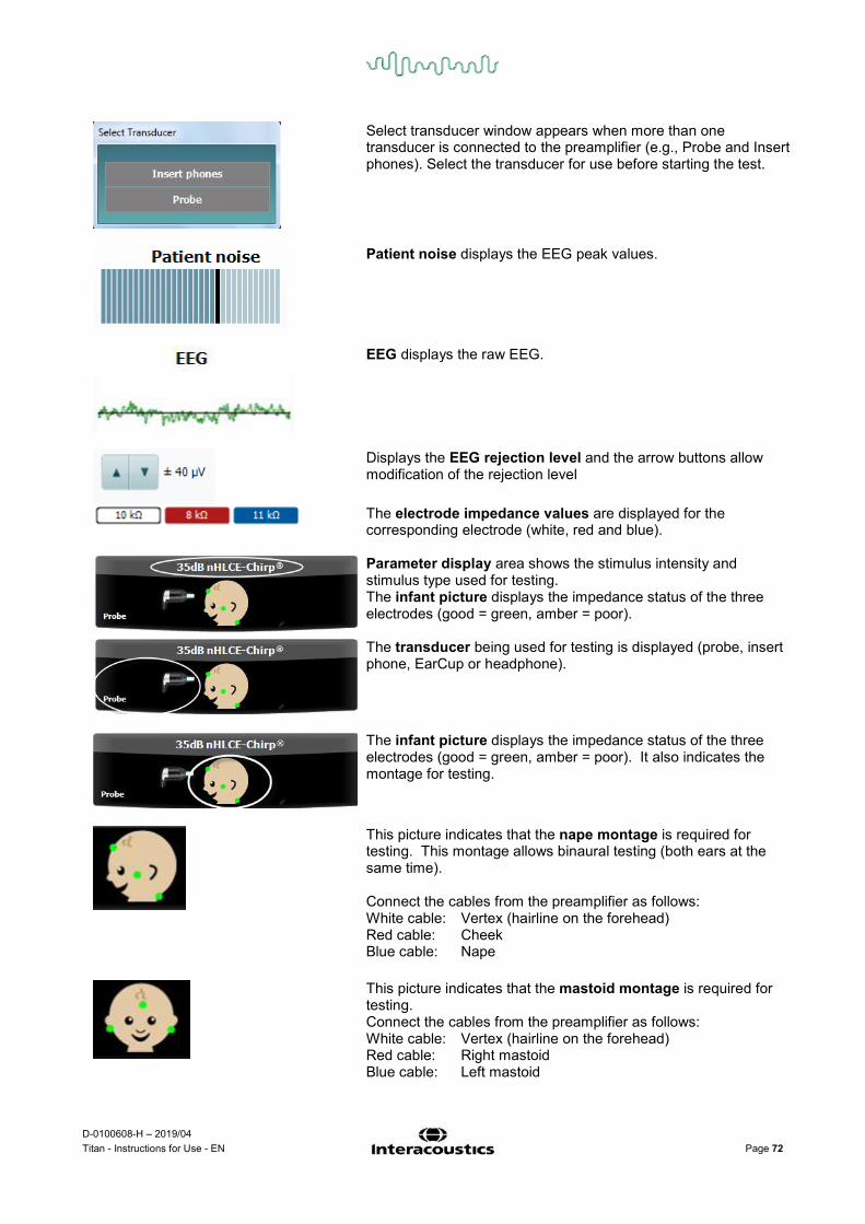
D-0100608-H – 2019/04 Titan - Instructions for Use - EN Page 72
Select transducer window appears when more than one transducer is connected to the preamplifier (e.g., Probe and Insert phones). Select the transducer for use before starting the test.
Patient noise displays the EEG peak values. EEG displays the raw EEG.
Displays the EEG rejection level and the arrow buttons allow modification of the rejection level
The electrode impedance values are displayed for the corresponding electrode (white, red and blue).
Parameter display area shows the stimulus intensity and stimulus type used for testing. The infant picture displays the impedance status of the three electrodes (good = green, amber = poor).
The transducer being used for testing is displayed (probe, insert phone, EarCup or headphone).
The infant picture displays the impedance status of the three electrodes (good = green, amber = poor). It also indicates the montage for testing.
This picture indicates that the nape montage is required for testing. This montage allows binaural testing (both ears at the same time). Connect the cables from the preamplifier as follows: White cable: Vertex (hairline on the forehead) Red cable: Cheek Blue cable: Nape
This picture indicates that the mastoid montage is required for testing. Connect the cables from the preamplifier as follows: White cable: Vertex (hairline on the forehead) Red cable: Right mastoid Blue cable: Left mastoid

D-0100608-H – 2019/04 Titan - Instructions for Use - EN Page 73
Impedance is not ideal warning window will appear if any of the electrode impedance indicators are amber in color. The user needs to confirm whether they wish to proceed with testing if impedance values are poor. Poor impedance can lead to longer test times and noisier recordings.
When enabled in the software, the Residual Noise value and the Residual Noise Stopping Criteria will be displayed. The Residual Noise value will update during the test as the measurement is progressing. If the Residual Noise value reaches the Stop testing at (nV) value before a Pass has been detected, the test will stop automatically and the result displayed will be a Refer. The efficiency of the method used for determining the residual noise level is described in the following article: Elberling, C., & Don, M. (1984). Quality estimation of average auditory brainstem responses. Scand Audiol, 13, 187-197.
Screening results can be PASS, REFER or INCOMPLETE and are indicated above the measurement as soon as the result is available. If the “Enabled Pass/Refer” checkbox is not checked for the selected protocol, no labeling will appear. The statistical significance of the factory CE-Chirp 35dBnHL protocol is: Algorithmic Sensitivity: 99.9% Specificity: > 96% For user defined protocol using settings or stimuli other than those in the factory protocol, the detected result is dependent upon a combination of the following settings defined in the protocol setup: Test time, stimulus type, stimulus intensity, weighting, residual noise limit.
EEG too high indicates that the EEG peak level causes rejection of the measurement.
Reconnect electrode indicates that the impedance of one of the electrodes is so high that either the electrode has lost contact with the skin or the electrode cable is disconnected or broken. All measurements are rejected while this message is displayed on screen.
EEG too low indicates that the impedance between electrodes is so low that it is likely that two or more electrodes have short circuited. All measurements are rejected while this message is displayed on screen.
Connect transducer means that there is no transducer connected the preamplifier.
Connect PreAmp indicates that the preamplifier is not connected to the Titan.
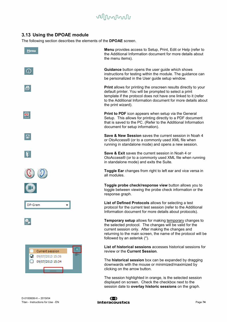
D-0100608-H – 2019/04 Titan - Instructions for Use - EN Page 74
Using the DPOAE module The following section describes the elements of the DPOAE screen.
Menu provides access to Setup, Print, Edit or Help (refer to the Additional Information document for more details about the menu items).
Guidance button opens the user guide which shows instructions for testing within the module. The guidance can be personalized in the User guide setup window.
Print allows for printing the onscreen results directly to your default printer. You will be prompted to select a print template if the protocol does not have one linked to it (refer to the Additional Information document for more details about the print wizard).
Print to PDF icon appears when setup via the General Setup. This allows for printing directly to a PDF document that is saved to the PC. (Refer to the Additional Information document for setup information).
Save & New Session saves the current session in Noah 4 or OtoAccess® (or to a commonly used XML file when running in standalone mode) and opens a new session.
Save & Exit saves the current session in Noah 4 or OtoAccess® (or to a commonly used XML file when running in standalone mode) and exits the Suite.
Toggle Ear changes from right to left ear and vice versa in all modules.
Toggle probe check/response view button allows you to toggle between viewing the probe check information or the response graph.
List of Defined Protocols allows for selecting a test protocol for the current test session (refer to the Additional Information document for more details about protocols).
Temporary setup allows for making temporary changes to the selected protocol. The changes will be valid for the current session only. After making the changes and returning to the main screen, the name of the protocol will be followed by an asterisk (*).
List of historical sessions accesses historical sessions for review or the Current Session. The historical session box can be expanded by dragging downwards with the mouse or minimized/maximized by clicking on the arrow button. The session highlighted in orange, is the selected session displayed on screen. Check the checkbox next to the session date to overlay historic sessions on the graph.

D-0100608-H – 2019/04 Titan - Instructions for Use - EN Page 75
Go to current session takes you back to the current session.
Probe status is shown by a colored bar with description next to it. When the probe status is Out of ear it will show the color of the selected ear (blue for left and red for right). When the probe is detected to be In ear the color is green. When Blocked, Leaking or Too Noisy the colored bar is amber. When No probe is detected the status bar is grey. See section 3.3 for information about probe statuses.
Summary view toggles between displaying result graph or result graph with test summary tables.
Monaural/Binaural view toggles between showing the results of a single ear or both ears.
Report editor button opens a separate window for adding and saving notes to the current or historic session.
Checking the Acceptable noise level Off box disables the rejection of any recording even when there is too much noise in the recording.
The Acceptable noise level slider allows setting the acceptable noise level limit between -30 and +30 dB SPL above which recordings are considered to be too noisy. The VU meter indicates the current noise level and becomes amber in color when exceeding the set level.
Pressure indicator shows whether the test is running at ambient or peak middle ear pressure. The Target indicator shows how far away the pressure is from the target. Peak pressure should be selected when wanting to perform a pressurized OAE test. You must run a tympanogram measurement in the IMP module first for the selected ear before testing with Peak pressure is possible.
The hardware indication picture indicates whether the
hardware is connected. Simulation mode is indicated when operating the software without hardware.
When opening the Suite the system will automatically search for the hardware. If it does not detect the hardware a dialog box pops up and asks if you want to continue in simulation mode.

D-0100608-H – 2019/04 Titan - Instructions for Use - EN Page 76
Before testing, the Timer symbol indicates after how much time the DPOAE test will automatically stop. During testing the timer counts down to zero. You can disable the countdown by clicking on the timer during testing. As a result the timer will begin counting up and indicate how much test time has passed. Then the test will continue until you manually press stop. When the measurement is rejecting, the timer will stop counting. Artifact rejection is dependent upon the Acceptable Noise Level setting and Level tolerance level set in the protocol.
The protocol listing shows all tests that are part of the selected protocol. The test that is displayed in the test screen area is highlighted blue or red, depending on the chosen ear.
A checkmark in the box indicates that the test will run when START is pressed. During testing the tests which have been completed will automatically become unchecked. Uncheck the boxes of tests you do not wish to run under the selected protocol before pressing START.
A white checkmark indicates that (at least some) data for this test is stored in the memory.
Pause becomes active after testing has started. It allows for pausing during a test.
START (and STOP) button are used for starting and stopping the session.
The probe check graph provides a visual display of the probe fit in the patient’s ear before and after testing. During testing, the probe check is not running and the graph will not display a curve.

D-0100608-H – 2019/04 Titan - Instructions for Use - EN Page 77
The response graph shows the response recorded by the probe microphone (in dB SPL) as a function of the frequency (in Hz). Only the frequency range that is relevant for the currently measured or currently selected point is plotted.
1. The two test stimuli are easily recognized as the two peaks in the response graph.
2. The stimulus tolerance range is indicated by two shaded areas above and below the peak of the stimulus.
3. The red or blue line indicates the DPOAE frequency at which the main distortion product is expected.
See the Additional Information document for further details.
Hovering the mouse over a measurement point shows details about the ongoing or finished measurement. See the Additional Information document for more specific details of each item in the mouse over table.
The DP found checkmark symbol, a black checkmark in a green circle, indicates that this individual measurement met its specified criterion and no further testing at this frequency will occur.
The DP found checkmark symbol, a black checkmark, indicates that this individual measurement met its specified criterion, but testing will continue until the test time runs out or the test is manually stopped.
The time out symbol, a clock, indicates that the measurement has ended without reaching the specified criterion for the individual point within the time allowed. In the general setup it can be chosen whether or not this type of indication is shown.
The noise floor symbol, an arrow pointing at a line, indicates that the measurement has ended because the residual noise floor limit was reached. In the general setup it can be chosen whether or not this type of indication is shown.

D-0100608-H – 2019/04 Titan - Instructions for Use - EN Page 78
Pointing at the desired graph and then using the scroll wheel of your mouse allows zooming in and out on the Response and DP-Gram graph. Once zoomed in on, the graph then can be dragged in respect to the frequency axis.
Right clicking on the DP-Gram graph provides the following options: The scroll wheel of your mouse allows zooming in and out with respect to the frequency axis. Additionally you can Zoom in, Zoom out or Restore view by selecting the appropriate item from the right mouse click menu.
Add an additional frequency after testing of the original protocol has finished. Point and right click your mouse at the frequency that you would like to test. Click on Add then select an available frequency from the list to measure. After adding one or more frequencies you will notice that the Start button changes to say Continue. Clicking Continue will measure all inserted frequencies without a time limit. Press Stop when the additional points are sufficiently tested.
Next measurement point interrupts the automatic test procedure and forces the Titan to start testing the next frequency immediately. This function is available when max test point has been selected in the protocol.
Measure only selected frequency results in re-testing the currently selected measurement point only. Select a measurement point to re-test by right clicking on it. A black circle around the measurement point indicates that it is selected. After pressing Continue (where the Start button was) the selected point will be tested without a time limitation. Press Stop to stop testing.
DPOAE norm data allows you to change which DP norm data is shown in the DP-Gram.

D-0100608-H – 2019/04 Titan - Instructions for Use - EN Page 79
Right clicking on the DP-I/O graph provides the following options: Add an additional level after testing of the original protocol has finished. Point and right click your mouse at the frequency that you would like to test. Click on Add then select an available level to additionally measure. After adding one or more levels you will notice that the Start button changes to say Continue. Clicking Continue will measure all inserted levels without a time limit. Press Stop when the additional points are sufficiently tested.
Next measurement point interrupts the automatic test procedure and forces the Titan to start testing at the next intensity immediately. This function is available when max test point has been selected in the protocol.
Measure only selected level results in re-testing the currently selected measurement point only. Select a measurement point to re-test by right clicking on it. A black circle around the measurement point indicates that it is selected. After pressing Continue (where the Start button was) the selected point will be tested without a time limitation. Press Stop to stop testing.
The minimum test requirements as defined in the protocol are displayed beside some of the items in the Test summary table. These numbers in parentheses change to a check mark when the minimum requirement has been met during testing.
The Point Summary table displays the f2 test frequencies, DP level, Noise, SNR and Reliability percentage. The Detected column displays a check mark when the specified frequency has met the criteria as setup in the protocol. DP level, Noise and SNR values are rounded based on raw data. Therefore, the calculated SNR value displayed may not always equal the DP level minus the Noise.
When the stimulus level goes outside the tolerance set in the protocol setup, the stimuli levels outside tolerance pop-up dialogue will appear on screen. Press Stop to stop testing. Check the probe fit and restart the test.

D-0100608-H – 2019/04 Titan - Instructions for Use - EN Page 80
Screening results can be PASS, REFER or INCOMPLETE and are indicated above the measurement as soon as the result is available. If the “Enabled Pass/Refer” checkbox is not checked for the selected protocol, no labeling will appear. The statistical significance of the detected result is dependent upon a combination of the following user defined settings in the protocol setup: Test time, Stimulus levels, SNR, Min DP level, DP tolerance, Reliability, Number of points required for a pass, Mandatory points required for a pass.

D-0100608-H – 2019/04 Titan - Instructions for Use - EN Page 81
Using the TEOAE tab The following section describes the elements of the TEOAE screen.
Menu provides access to Setup, Print, Edit or Help (refer to the Additional Information document for more details about the menu items).
Guidance button opens the user guide which shows instructions for testing within the module. The guidance can be personalized in the User guide setup window.
Print allows for printing the onscreen results directly to your default printer. You will be prompted to select a print template if the protocol does not have one linked to it (refer to the Additional Information document for more details about the print wizard).
Print to PDF icon appears when setup via the General Setup. This allows for printing directly to a PDF document that is saved to the PC. (Refer to the Additional Information document for setup information).
Save & New Session saves the current session in Noah 4 or OtoAccess® (or to a commonly used XML file when running in standalone mode) and opens a new session.
Save & Exit saves the current session in Noah 4 or OtoAccess® (or to a commonly used XML file when running in standalone mode) and exits the Suite.
Toggle Ear changes from right to left ear and vice versa in all modules.

D-0100608-H – 2019/04 Titan - Instructions for Use - EN Page 82
List of Defined Protocols allows for selecting a test protocol for the current test session (refer to the Additional Information document for more details about protocols).
Temporary setup allows for making temporary changes to the selected protocol. The changes will be valid for the current session only. After making the changes and returning to the main screen, the name of the protocol will be followed by an asterisk (*).
List of historical sessions accesses historical sessions for review or the Current Session. The historical session box can be expanded by dragging downwards with the mouse or minimized/maximized by clicking on the arrow button. The session highlighted in orange, is the selected session displayed on screen. Check the checkbox next to the session date to overlay historic sessions on the graph.
Go to current session takes you back to the current session.
Probe status is shown by a colored bar with description next to it. When the probe status is Out of ear it will show the color of the selected ear (blue for left and red for right). When the probe is detected to be In ear the color is green. When Blocked, Leaking or Too Noisy the colored bar is amber. When No probe is detected the status bar is grey. See section 3.3 for information about probe statuses.
Summary view toggles between displaying result graph or result graph with test summary tables.
Monaural/Binaural view toggles between showing the results of a single ear or both ears.
Report editor button opens a separate window for adding and saving notes to the current or historic session.
The Acceptable noise level slider allows setting the acceptable noise level limit between +30 and +60 dB SPL. Sweeps recorded above the set acceptable noise level are considered to be too noisy and are rejected. The VU meter indicates the current noise level and becomes amber in color when exceeding the set level.
Pressure indicator shows whether the test is running at ambient or peak middle ear pressure. The Target indicator shows how far away the pressure is from the target.

D-0100608-H – 2019/04 Titan - Instructions for Use - EN Page 83
Peak pressure should be selected when wanting to perform a pressurized OAE test. You must run a tympanogram measurement in the IMP module first for the selected ear before testing with Peak pressure is possible.
The hardware indication picture indicates whether the hardware is connected. Simulation mode is indicated when operating the software without hardware.
When opening the Suite the system will automatically search for the hardware. If it does not detect the hardware a dialog box pops up and asks if you want to continue in simulation mode.
Before testing, the Timer symbol indicates after how much time the TEOAE test will automatically stop. During testing the timer counts down to zero. You can disable the countdown by clicking on the timer during testing. As a result the timer will begin counting up and indicate how much test time has passed. Then the test will continue until you manually press stop. When the measurement is rejecting, the timer will stop counting. Artifact rejection is dependent upon the Acceptable Noise Level setting and Level tolerance level set in the protocol.
The protocol listing shows all tests that are part of the selected protocol. The test that is displayed in the test screen area is highlighted blue or red, depending on the chosen ear.
A checkmark in the box indicates that the test will run when START is pressed. During testing the tests which have been completed will automatically become unchecked. Uncheck the boxes of tests you do not wish to run under the selected protocol before pressing START.
A white checkmark indicates that (at least some) data for this test is stored in the memory.
Pause becomes active after testing has started. It allows for pausing during a test.
START (and STOP) button are used for starting and stopping the session.

D-0100608-H – 2019/04 Titan - Instructions for Use - EN Page 84
The SNR (Signal-to-noise ratio) is displayed within each of the frequency bands tested and is calculated in dB. Hovering the mouse over a frequency band shows details about the ongoing or finished measurement.
Pointing at the desired graph and then using the scroll wheel of your mouse allows zooming in and out on all graphs.
It is possible to change the view of the TE response graph by right clicking. The dropdown menu gives the following options: View allows you to change from the Original view to FFT view, 1/1, 1/2, 1/3, 1/6 and 1/12 octave band display. Extend test allows continued testing after the test has ended on its own or been manually stopped. The counter will revert to 0 and start counting without a time limitation. Press Stop to stop testing. Extend test is only available when the protocol is not enabled for PASS/REFER. Norm data allows you to change which TE norm data is displayed in the TE response graph.
The response waveform along with the recording window and response reproducibility range are shown. The arrows indicate the recording window start and stop time. The area outside the recording window is grayed out. The recording window start and stop time can be changed prior to starting a test by moving the arrows on the graph with the mouse,

D-0100608-H – 2019/04 Titan - Instructions for Use - EN Page 85
The waveform reproducibility window range is indicated by a black line on the x axis. Only the waveform within this range accounts for the calculation of the waveform reproducibility percentage. Clicking on the aqua or purple circles at the end of each waveform and moving the mouse, allows for separation of the curves within the graph
Right clicking on the response waveform graph allows for changing the display. View buffers A & B is the default view showing the two superimposed averaged OAE waveforms. View noise displays the noise in the waveform (Noise = A buffer – B buffer). View average displays the mean of the A and B waveforms.
The minimum test requirements as defined in the protocol are displayed beside some of the items in the Test summary table. These numbers in parentheses change to a check mark when the minimum requirement has been met during testing.
The Band Summary table displays the test frequencies, TE level, Noise, SNR. The Detected column displays a check mark when the specified frequency has met the criteria as setup in the protocol. TE level, Noise and SNR values are rounded based on raw data. Therefore, the calculated SNR value displayed may not always equal the TE level minus the Noise.
When the stimulus level goes outside the tolerance set in the protocol setup, the stimulus levels outside tolerance pop-up dialogue will appear on screen. Try repositioning the probe in the ear. When the probe is reinserted, the dialog box will automatically disappear if the stimulus goes back within the tolerance range and testing will continue. Press Stop to stop testing.

D-0100608-H – 2019/04 Titan - Instructions for Use - EN Page 86
Screening results can be PASS, REFER or INCOMPLETE and are indicated above the measurement as soon as the result is available. If the “Enabled Pass/Refer” checkbox is not checked for the selected protocol, no labeling will appear. The statistical significance of the detected result is dependent upon a combination of the following user defined settings in the protocol setup: Test time, Stimulus level. SNR, Recording Window, Min Total OAE, Min Reproducibility, Min TE level, Number of bands required for a pass, Mandatory bands required for a pass.

D-0100608-H – 2019/04 Titan - Instructions for Use - EN Page 87
Using the Print Wizard In the Print Wizard you have the option to create customized print templates which can be linked to individual protocols for quick printing. The Print Wizard can be reached in two ways.
a. If you want to make a template for general use, or select an existing one for printing: Go to Menu | Print | Print wizard… in any of the Titan Suite tabs (IMP, DPOAE, TEOAE or ABRIS)
b. If you want to make a template or select an existing one to link to a specific protocol: Go to Module tab (IMP, DPOAE, TEOAE or ABRIS) relating to the specific protocol and select Menu | Setup | Protocol setup. Select the specific protocol from the drop down menu and select Print Wizard at the bottom of the window
Now the Print Wizard window opens and shows the following information and functionalities:
1. Underneath Categories you can select
• Templates to show all available templates • Factory defaults to show only standard templates • User defined to show only custom templates • Hidden to show hidden templates • My favorites to show only templates marked as a favorite
2. Available templates from the selected category are shown in the Templates viewing area. 3. Factory default templates are recognized by the lock icon. They ensure that you always have a
standard template and do not need to create a customized one. However, they cannot be edited according to personal preferences without resaving with a new name. User defined/created templates can be set to Read-only (showing the lock icon), by right clicking on the template and selecting Read-only from the drop down list. Read-only status can also be removed from User defined templates by following the same steps.
4. Templates added to My favorites are marked with a star. Adding templates to My favorites allows quick viewing of your most commonly used templates.
5. The template that is attached to the selected protocol when entering the print wizard via the IMP440, ABRIS440, DPOAE440 or TEOAE440 window is recognized by a checkmark.
6. Press the New Template button to open a new empty template.
1 2 3 4
5
6
11 12a 13
12b

D-0100608-H – 2019/04 Titan - Instructions for Use - EN Page 88
7. Select one of the existing templates and press the Edit Template button to modify the selected layout.
8. Select one of the existing templates and press the Delete Template button to delete the selected template. You will be prompted to confirm that you want to delete the template.
9. Select one of the existing templates and press the Hide Template button to hide the selected template. The template will now be visible only when Hidden is selected under Categories. To unhide the template, select Hidden under Categories, right click on the desired template and select View/Show.
10. Select one of the existing templates and press the My Favorites button to mark the template as a favorite. The template can now be quickly found when My Favorites is selected under Categories. To remove a template marked with a star from My Favorites, select the template and press the My Favorites button.
11. Select one of the templates and press the Preview button to print preview the template on screen. 12. Depending how you reached the Print Wizard, you will have the option to press
a. Print for using the selected template for printing or press b. Select for dedicating the selected template to the protocol from which you got into the Print
Wizard 13. To leave the Print Wizard without selecting or changing a template press Cancel.
Right clicking on a specific template provides a drop down menu offering an alternative method for performing the options as described above: More detailed information about the Print Wizard can be found in the Titan Additional Information document.

D-0100608-H – 2019/04 Titan - Instructions for Use - EN Page 89
4 Maintenance General maintenance procedures
The performance and safety of the instrument will be maintained if the following recommendations for care and maintenance are observed:
1. It is recommended that the instrument go through at least one annual service, to ensure that the acoustical, electrical and mechanical properties are correct. This should be carried out by an authorized repairer in order to guarantee proper service and repair.
2. Observe that no damage is present to the insulation of the mains cable or the connectors and that it is not exposed to any kind of mechanical load that could involve damage.
3. To ensure that the reliability of the instrument is maintained, we recommend that the operator at short intervals, for instance once a day, performs a test on a person with known data. This person could be the operator. For TEOAE, a daily probe test is recommended to confirm the probe is functioning properly before testing on patients.
4. If the surface of the instrument or parts of it is contaminated, it can be cleaned using a soft cloth moistened with a mild solution of water and detergent or similar. Always disconnect the mains power adaptor and battery during the cleaning process, and be careful that no fluid enters the inside of the instrument or accessories.
5. After each patient examination, ensure that there has been no contamination to the parts touching the patient. General precautions must be observed in order to avoid cross-contamination of disease from one patient to another. If ear cushions or are contaminated, it is strongly recommended to remove them from the transducer before they are cleaned. Water should be used for frequent cleaning, but in the case of severe contamination it may be necessary to use a disinfectant.
• Before cleaning always switch off and disconnect from the power supply • Use a soft cloth lightly dampened with cleaning solution to clean all exposed surfaces • Do not allow liquid to come in contact with the metal parts inside the earphones / headphones • Do not autoclave, sterilize or immerse the instrument or accessory in any fluid • Do not use hard or pointed objects to clean any part of the instrument or accessory • Do not let parts that have been in contact with fluids dry before cleaning • Rubber ear-tips or foam ear-tips are single use components • Ensure that isopropyl alcohol does not come into contact with any screens on the instruments • Ensure that isopropyl alcohol does not come into contact with any silicone tubes or rubber parts
Recommended cleaning and disinfection solutions:
• Warm water with mild, nonabrasive cleaning solution (soap) • 70% isopropyl alcohol only on hard cover surfaces
Procedure • Clean the instrument by wiping outer case with a lint free cloth lightly dampened in cleaning solution • Clean cushions and patient hand switch and other parts with a lint free cloth lightly dampened in
cleaning solution • Make sure not to get moisture in the speaker portion of the earphones and similar parts

D-0100608-H – 2019/04 Titan - Instructions for Use - EN Page 90
Cleaning the probe tip In order to secure correct measurements, it is important to make sure that the probe system is kept clean at all times. Therefore, please follow the below illustrated instructions on how to remove e.g. cerumen from the small acoustic and air pressure channels of probe tip. Probe, Short Extension Cable, Preamplifier
Clinical Extension Cable
1. Unscrew the probe cap.
2. Remove the probe tip.
3. Thread the stiff end of the cleaning floss into one of the tubes.
4. Pull the cleaning floss completely through the probe tip tube. Clean each of the tubes as required. Discard floss after use.
5. Assemble the probe again.
Notice: Do not use the cleaning tool to clean the probe base. This will destroy the filters.

D-0100608-H – 2019/04 Titan - Instructions for Use - EN Page 91
Concerning repair Interacoustics is only considered to be responsible for the validity of the CE marking, effects on safety, reliability and performance of the equipment if:
1. assembly operations, extensions, readjustments, modifications or repairs are carried out by authorized persons,
2. a 1 year service interval is maintained 3. the electrical installation of the relevant room complies with the appropriate requirements, and 4. the equipment is used by authorized personnel in accordance with the documentation supplied by
Interacoustics.
It is important that the customer (agent) fills out the RETURN REPORT every time a problem arises and sends it to DGS Diagnostics Sp. z o.o., ul. Sloneczny Sad 4d, 72-002 Doluje, Polska. This should also be done every time an instrument is returned to Interacoustics. (This of course also applies in the unlikely worst case scenario of death or serious injury to a patient or user).
Warranty INTERACOUSTICS guarantees that:
• The Titan is free from defects in material and workmanship under normal use and service for a period of 24 months from the date of delivery by Interacoustics to the first purchaser
• Accessories are free from defects in material and workmanship under normal use and service for a period of ninety (90) days from the date of delivery by Interacoustics to the first purchaser
If any product requires service during the applicable warranty period, the purchaser should communicate directly with the local Interacoustics service centre to determine the appropriate repair facility. Repair or replacement will be carried out at Interacoustics’ expense, subject to the terms of this warranty. The product requiring service should be returned promptly, properly packed, and postage prepaid. Loss or damage in return shipment to Interacoustics shall be at purchaser's risk. In no event shall Interacoustics be liable for any incidental, indirect or consequential damages in connection with the purchase or use of any Interacoustics product. This shall apply solely to the original purchaser. This warranty shall not apply to any subsequent owner or holder of the product. Furthermore, this warranty shall not apply to, and Interacoustics shall not be responsible for, any loss arising in connection with the purchase or use of any Interacoustics product that has been:
• repaired by anyone other than an authorized Interacoustics service representative • altered in any way so as, in Interacoustics opinion, to affect its stability or reliability • subject to misuse or negligence or accident, or that has had the serial or lot number altered,
defaced or removed; or • improperly maintained or used in any manner other than in accordance with the instructions
provided by Interacoustics
This warranty is in lieu of all other warranties, express or implied, and of all other obligations or liabilities of Interacoustics. Interacoustics does not give or grant, directly or indirectly, the authority to any representative or other person to assume on behalf of Interacoustics any other liability in connection with the sale of Interacoustics products. INTERACOUSTICS DISCLAIMS ALL OTHER WARRANTIES, EXPRESSED OR IMPLIED, INCLUDING ANY WARRANTY OF MERCHANTABILITY OR FOR FUNCTION OF FITNESS FOR A PARTICULAR PURPOSE OR APPLICATION.

D-0100608-H – 2019/04 Titan - Instructions for Use - EN Page 92

D-0100608-H – 2019/04 Titan - Instructions for Use - EN Page 93
5 General technical specification Titan hardware – technical specifications
Medical CE-mark The CE-mark indicates that Interacoustics A/S meets the requirements of Annex II of the Medical Device Directive 93/42/EEC. Approval of the quality system is made by TÜV – identification no0123
Standards Safety: IEC 60601-1: 2005, Internally powered, Type B and BF applied parts EMC: IEC 60601-1-2: 2014 Impedance: IEC 60645-5:2004 /ANSI S3.39, Type 1 Test Signal: IEC 60645-1:2012 /ANSI S3.6 , IEC 60645-3: 2007 OAE: IEC 60645-6:2009, TEOAE Type 1 & 2 Otoacoustic emissions
IEC 60645-6:2009, DPOAE Type 2 Otoacoustic emissions ABR: IEC 60645-7: 2009, Type 2 FIPS: Complaint in accordance with FIPS PUB 140-2 Cradle
Safety: Power Mains voltages and frequencies: Consumption:
IEC 60601-1:2014, Class II Astrodyne ASA30M-0301 or UE24WCP 100 – 240 VAC, 47 – 63 Hz 0.8 – 0.4 A
Battery Use only: NP120 or CGA103450 Operation environment Temperature: 15 – 35 °C Relative Humidity: 30 – 90% Ambient Pressure: 98kPa – 104kPa Warm-up Time: 1 minute Transport & Storage Storage Temperature:
Transport Temperature: Rel. Humidity:
0°C – 50°C -20 – 50 °C 10 – 95%
Impedance measuring system Probe tone Frequency:
Level:
Classic tympanometry: 226 Hz, 678 Hz, 800 Hz, 1000 Hz; pure tones; AGC controlled to protect for loud probe tone stimuli in small ear canals. WBT: 226 Hz – 8000 Hz broadband stimulus, 21.5/sec. 226 Hz: 85 dB SPL (≈ 69 dB HL) WBT: 96 dB peSPL (infant) / 100 dB peSPL (adult). (100 dB peSPL ≈ 65 dB nHL)
Air pressure Control: Indicator: Range: Pressure limitation: Pressure change rate:
Automatic. Measured value is displayed on the graphical display. -600 to +300 daPa. -750 daPa and +550 daPa. Minimum, medium, maximum or automatic with minimum speed at compliance peak. Selectable in the setup.
Compliance Range: 0.1 to 8.0 ml at 226 Hz probe tone (Ear volume: 0.1 to 8.0 ml) and 0.1 to 15 mmho at 678, 800 and 1000 Hz probe tone.
Test types Tympanometry Automatic, where the start and stop pressure can be user-programmed in the setup function. Manual control of all functions.
Eustachian tube function 1 – Non perforated eardrum
Williams test
Eustachian tube function 2 – Perforated eardrum
Toynbee test
Eustachian tube function 3 – Patulous Eustachian tube
Continuous sensitive impedance measurement for 30 up to 150 s.
Indicators Graphical display Compliance is indicated as ml and pressure as daPa. In PC controlled mode admittance, susceptance and conductance can be printed. Stimulus level is indicated as dB Hearing Level.

D-0100608-H – 2019/04 Titan - Instructions for Use - EN Page 94
Memory Tympanometry:
1 curve per ear per tympanometry test. 3 curves per ear per Eustachian tube function test. And theoretically an infinite number of tests per protocol.
There is no deviation between static and dynamic mode. Reflex functions Signal sources Tone - Contra, Reflex: 250, 500, 1000, 2000, 3000, 4000, 6000, 8000 Hz. Tone - Ipsi, Reflex: 500, 1000, 2000, 3000, 4000 Hz. NB noise - Contra, Reflex: 250, 500, 1000, 2000, 3000, 4000, 6000, 8000 Hz. NB noise - Ipsi, Reflex: 1000, 2000, 3000, 4000 Hz. Noise - Contra, Reflex: Wide Band, High Pass, Low Pass. Noise - Ipsi, Reflex: Wide Band, High Pass, Low Pass. Stimulus duration: 750 ms (continuous) Outputs Contra Earphone: TDH39 earphone, DD45 earphone, CIR55 insert and/or E-A-RTONE
3A/IP30 insert for Reflex measurements. Ipsi Earphone: Probe earphone incorporated in the probe system for Reflex
measurements. Air: Connection of the air system to the probe. Test types Manual Reflex Manual control of all functions. Automated Reflex Automatic reflexes:
- Single intensities - Reflex growth
Reflex Decay Automatic, 10 dB above threshold and manually controlled with stimulus durations of 10 to 30 s.
Reflex latency Automated, first 300 ms from stimulus start.
ABR infant screening Preamplifier One Channel: 3 electrodes. 50 cm
Switchable: Software will automatically switch mastoid and ground electrodes if the mastoid montage is used. The user does not need to change the electrodes during testing.
Gain: 64 dB Frequency response: 0,5 - 5000 Hz Noise: <25 nV/√Hz CMR Ratio: >90 dB. Max input offset voltage: 2.5 V Input impedance: 10 MΩ/ 170 pF Power from main unit: Isolated power supply Electrical Impedance measurement
Measurement frequency: 33 Hz
Waveform: Rectangular Measurement current: 11.25 μA Range: 0.5 kΩ – 25 kΩ ± 10 % Stimulus Stimuli: Click range (200 Hz -11 kHz)
CE-Chirp® range (200 Hz – 11 kHz) HiLo CE-Chirp® range (Lo – up to 1.5 kHz) & (Hi – above 1.5 kHz)
Stimulus rate: 90 Hz Transducers:
(Calibrated to Standards) E-A-RTONE ABR insert phone E-A-RTONE ABR for EarCup IP30 ABR insert phone IP30 ABR for EarCup TDH 39 or DD45 head phone (Static force: 4,5N ± 0,5N) IOW Probe
Level: 30 dB nHL, 35 dB nHL, 40 dB nHL Bandwidth: 22.05 kHz Recording Analysis time: 1-10 min or Residual noise 5-80 nV A/D resolution: 24 bit Artifact reject system: Rejection level (Peak, Min RMS, Max RMS) & Clipping (Saturation) Display
Stimulus level and type, transducer, rejection level, electrode impedances, EEG/noise, bar or curve view, test time.
Algorithmic Sensitivity CE-Chirp®: 99.9% Specificity CE-Chirp®: > 96%

D-0100608-H – 2019/04 Titan - Instructions for Use - EN Page 95
DPOAE Stimulus Frequency range: 500 to 10000 Hz Nominal frequency: f2 Frequency step: 1 Hz Level: 30 to 80 dB SPL (75 dB SPL for 6kHz and 65 dB SPL for 8kHz to
10kHz) Level Step: 1 dB Transducer:
Recording Analysis time: 1 second to unlimited time A/D Resolution: 24 bit, 5.38 Hz resolution Artifact rejection system: -30 to +30 dB SPL or off Stimulus tolerance: Adjustable between 1 and 10 dB SNR criteria: Adjustable between 3 and 25 dB DP criteria: SNR, Min DP level, DP tolerance, Residual noise, mandatory points,
DP reliability Probe check window: 256 points frequency response of the ear canal due to a click stimulus. DP-response window: 4096 points frequency response
Residual noise: A RMS average measurement in the DP-bin frequency area (26 bins at frequencies < 2500 Hz & 60 bins ≥ 2500 Hz).
Display Other information: In ear status (before/after test), noise rejection level, tympanic peak pressure Basic or advanced view of the DP-Gram, test summary table, point summary table
Probe specifications Titan IOWA probe: Clinical extension cable with fixed IOWA probe. Auto detection and auto calibrated. IMP, DPOAE and TEOAE capable
Replaceable probe tip Test Pressure Ambient pressure
Tympanic peak pressure (from IMP module)
TEOAE Stimulus Frequency range: 500 to 5500 Hz Frequency step: 1 Hz (Custom bands) Stimulus type: Non-Linear and Linear (according to IEC 60645-3) Level: 30 to 90 dB peSPL, peak to peak calibrated, AGC controlled Level step: 1 dB Click rate: 43.5 Hz or 80 Hz Stimulus tolerance: Adjustable between 1 and 3 dB Recording Analysis time: 30 seconds to 30 minutes or 300 to 30000 sweeps A/D Resolution: 24 bit Artifact rejection system: 0 to +60 dB SPL SNR criteria: Adjustable between 5 and 25 dB TE criteria: SNR, min sweeps, min Total OAE, min TE level, mandatory bands Stimulus time window: 128 points instant recording of first click in sequence of clicks Probe check window: 256 points frequency response of the ear canal recorded click stimulus Time recording window: 4 – 23 msec (max). A and B buffer time-samples @ sampling rate
11025 Hz Freq. response window: 256 points frequency response, bin spacing 43 Hz Residual noise: A RMS value for each octave band, based on the Bayesian weighted
average for the defined OAE time window Display Other information: In ear status (active before during & after test), noise rejection level,
tympanic peak pressure
Basic or advanced view, FFT view, test summary table. band summary table
Probe specifications Titan IOWA probe: Clinical extension cable with fixed IOWA probe. Auto detection and auto calibrated. IMP, DPOAE and TEOAE capable.
Replaceable probe tip Test Pressure Ambient pressure
Tympanic peak pressure (from IMP module)

D-0100608-H – 2019/04 Titan - Instructions for Use - EN Page 96
General PC control USB: Titan can be fully operated from a PC via a USB connection.
Data can be stored on the device in handheld mode and transferred and saved on the PC in a database (OtoAccess® or Noah) via USB.
Wireless: Titan can be fully operated from a PC using a wireless connection.. Data can be stored on the device in handheld mode and transferred wirelessly and saved on the PC in a database (OtoAccess® or Noah).
Memory The Titan includes a built-in 8 GB memory card. PC storage capacity is limited to the size of the database (OtoAccess® or Noah). It is recommended to store a maximum of 250 clients on the device.
Thermal printer (Optional) Type: Thermal printer with recording paper in rolls. Print on command through wireless communication or via a serial RS-232 connection.
Paper width: 57.5 ± 0.5 mm on thermal printer Printing time: Printing time depends on the size of the used protocol. For 2
tympanograms and 8 reflexes the thermal printer uses approximately 6s.
User interface Screen type: TFT with LED backlight Display size: 3.4 x 4.5 cm / 1.3 x 1.7 inches Dimensions 6 x 6 x 28 cm / 2.4 x 2.4 x 11 inches Titan Weight 360 g / 0.8 lbs Preamplifier weight 120 g / 0.26 lbs Preamplifier dimensions 10.2 x 6.8 x 2.6 cm / 4 x 2.7 x 1 inches Preamplifier cable length Short extension cable length
40 cm / 15.7 inches
Long extension cable shoulder box weight
66 g / 0.14lbs
Long extension cable shoulder box dimensions
9.5 x 4.5 x 2.2 cm / 3.7 x 1.8 x 0.8 inches
Long extension cable length
234 cm / 92 inches

D-0100608-H – 2019/04 Titan - Instructions for Use - EN Page 97
Table 1: Frequencies and intensity ranges for IMP440 Titan Maximums IMP
TDH39 CIR55 E-A-RTONE 3A/IP30 IOW IPSI DD45
Center Reading Reading Reading Reading Reading
Freq. Tone NB Tone NB Tone NB Tone NB Tone [dB HL]
NB
[Hz] [dB HL] [dB HL] [dB HL] [dB HL] [dB HL] [dB HL] [dB HL] [dB HL] [dB HL]
125 80 65 85 70 100 85 70 60 80 65
250 100 85 100 85 110 100 85 75 100 85
500 120 100 110 100 115 105 100 85 115 100
750 120 105 110 105 120 110 100 85 120 105
1000 120 105 115 105 120 110 105 90 120 105
1500 120 105 115 105 120 110 110 90 115 100
2000 120 105 115 105 120 110 105 90 115 100
3000 120 105 115 105 120 110 95 90 125 105
4000 120 105 110 100 120 105 100 90 115 105
6000 120 100 95 95 105 100 85 80 110 90
8000 105 95 80 85 90 85 80 75 105 95
10000
WB - 120 - 120 - 120 - 105 - 125
LP - 120 - 120 - 120 - 110 - 120
HP - 120 - 120 - 120 - 105 - 130
Table 2: Frequencies and Intensity Ranges for DPOAE440 Titan Maximums DPOAE
Center Freq. [Hz]
IOWA IPSI IOWA ch2 Reading Reading
Tone Tone
[dB SPL] [dB SPL]
500 80 80
750 80 80
1000 80 80
1500 80 80
2000 80 80
3000 80 80
4000 80 80
6000 75 75
8000 65 65
10000 65 65
Titan Maximums TEOAE Maximum TEOAE Click Intensity: 90 dB peSPL. Titan Maximums ABRIS Maximum ABRIS levels for Click and CE-Chirp® stimuli are limited to 30, 35 & 40 dB nHL for all transducers.

D-0100608-H – 2019/04 Titan - Instructions for Use - EN Page 98
Specification of input/output connections Outputs Phones, Left/ Right Jack, 3,5mm
4-pole Voltage: Min. load impedance: Pin 1: CH1 GND Pin 2: CH1 OUT (left) Pin 3: CH2 OUT (right) Pin 4: CH1 GND
Up to 3V rms. by 10Ω load 8Ω Pin 3:
Phones, Contralateral
Jack, 3,5mm 4-pole
Voltage: Min. load impedance: Pin 1: CH1 GND Pin 2: CH1 OUT (left) Pin 3: CH2 OUT (right) Pin 4: CH1 GND
Up to 3V rms. by 10Ω load 8Ω
Transducer IA proprietary, 12-pole
Pin 1: Pin 2: Pin 3: Pin 4: Pin 5: Pin 6: Pin 7: Pin 8: Pin 9: Pin 10: Pin 11: Pin 12:
CH1 out CH1 GND DGND GND A / GND Microphone Microphone – input / Analog balanced in Microphone + input / Analog balanced in Power supply +3/+5V CH2 out CH2 GND I2C CLK I2C DATA I2C Interrupt
Data I/O USB USB type”B” USB port for communication

D-0100608-H – 2019/04 Titan - Instructions for Use - EN Page 99
Calibration properties Calibrated Transducers
Contralateral Earphone: TDH39 or DD45 with a static force of 4.5N ±0.5N and/or E-A-RTONE 3A/IP30 and/or CIR55 insert phone
Probe system: Ipsilateral Earphone: is integrated in the probe system Probe frequency transmitter and receiver and
pressure transducer is integrated in the probe system Accuracy General: Generally, the instrument is made and calibrated to
be within and better than the tolerances required in the specified standards:
Reflex Frequencies: ±1% Contralateral Reflex and
Audiometer Tone Levels: ±3 dB for 250 to 4000Hz and ±5 dB for 6000 to 8000Hz
Ipsilateral Reflex Tone Levels:
±5 dB for 500 to 2000Hz and +5/-10 dB for 3000 to 4000Hz
DPOAE Levels: ±1.5 dB for 1000 to 4000Hz and ±3 dB outside range TEOAE Levels:
ABRIS Levels: Pressure measurement: Compliance measurement:
±2 dB for click stimulus ±2 dB for all stimulus types ±5% or ±10 daPa, whichever is greater ±5% or ±0.1 ml, whichever is greater
Stimulus Presentation Control
Reflexes: ON-OFF ratio = ≥ 70 dB Rise time = 27 ms Fall time = 24.6 ms A weighted SPL in Off = 31 dB
Impedance calibration properties Probe tone Frequencies: 226 Hz ± 1%, 678 Hz ± 1%, 800 Hz ± 1%, 1000 Hz
± 1% Level: 85 dB SPL ±1.5 dB measured in an IEC 60318-5
acoustic coupler. The level is constant for all volumes in the measurement range.
Distortion: Max 1% THD Compliance Range: 0.1 to 8.0 ml Temperature dependence: -0.003 ml/°C Pressure dependence: -0.00020 ml/daPa Reflex sensitivity:
Reflex artifact level: 0.001 ml is the lowest detectable volume change ≥95 dB SPL (measured in the 711 coupler, 0.2 ml, 0.5 ml, 2.0 ml & 5.0 ml hardwalled cavities).
Temporal reflex characteristics:
Initial latency = 35 ms (±5 ms) Rise time = 45 ms (±5 ms) Terminal latency = 35 ms (±5 ms) Fall time = 45 ms (±5 ms) Overshoot = max. 1% Undershoot = max 1%
Pressure Range: Values between -600 to +300 daPa can be selected in the setup.
Safety limits: -750 daPa and +550 daPa, ±50 daPa

D-0100608-H – 2019/04 Titan - Instructions for Use - EN Page 100
Reflex calibration standards and spectral properties: General Specifications for stimulus and audiometer signals are made to follow IEC 60645-5
Contralateral Earphone
Pure tone: ISO 389-1 for TDH39/DD45 and ISO 389-2 for CIR 55.
Wide Band noise (WB): − Spectral properties:
Interacoustics Standard As “Broad band noise” specified in IEC 60645-5, but with 500 Hz as lower cut-off frequency.
Low Pass noise (LP): − Spectral properties:
Interacoustics Standard Uniform from 500 Hz to 1600 Hz, ±5 dB re. 1000 Hz level
High Pass noise (HP): − Spectral properties:
Interacoustics Standard Uniform from 1600 Hz to 10KHz, ±5 dB re. 1000 Hz level
Ipsilateral Earphone Pure tone: Interacoustics Standard. Wide Band noise (WB):
− Spectral properties: Interacoustics Standard As “Broad band noise” specified in IEC 60645-5, but with 500 Hz as lower cut-off frequency.
Low Pass noise (LP): − Spectral properties:
Interacoustics Standard Uniform from 500 Hz to 1600 Hz, ±10 dB re. 1000 Hz level
High Pass noise (HP): − Spectral properties:
Interacoustics Standard Uniform from 1600 Hz to 4000 Hz, ±10 dB re. 1000 Hz level
General about levels: The actual sound pressure level at the eardrum will depend on the volume of the ear. See Table 2 for details.
The risk of artifacts at higher stimulus levels in reflex measurements are minor and will not activate the reflex detection system

D-0100608-H – 2019/04 Titan - Instructions for Use - EN Page 101
Table 3: Reference values for stimulus calibration (impedance) Freq. Reference values for stimulus calibration
[dB re. 20 µPa]
Variation of Ipsi stimulus levels for different volumes of the ear canal Relative to the calibration performed on an IEC 126 coupler [dB]
Sound attenuation values for TDH39 earphones using MX41/AR or PN51 cushion [dB]
ISO
389
-1
(Inte
raco
ustic
s St
anda
rd)
ISO
389
-2
(Inte
raco
ustic
s St
anda
rd)
ISO
382
-2
(Inte
raco
ustic
s St
anda
rd)
ISO
389-
1 In
tera
cous
tics
Stan
dard
In
tera
cous
tics
Stan
dard
Inte
raco
ustic
s St
anda
rd
ISO
389
-4
(ISO
879
8)
0.5 ml
1 ml
[Hz]
TDH39
E-A-R TONE 3A/ IP30 insert
CIR55
DD45
IOW/ IOWA Probe
IOW/ IOWA Probe NB
NB stimulus correction values (except IOW/IOWA probe)
RET
SPL
125 45 26 26 47.5 41 43.5 4 3 250 25.5 14 14 27 24.5 26.5 4 5 500 11.5 5.5 5.5 13 9.5 17 4 9.7 5.3 7 1000 7 0 0 6 6.5 10.5 6 9.7 5.3 15 1500 6.5 2 2 8 5 12 6 21 (1600Hz) 2000 9 3 3 8 12 11 6 11.7 3.9 26 3000 10 3.5 3.5 8 11 11 6 -0.8 -0.5 31 (3150Hz) 4000 9.5 5.5 5.5 9 3.5 8 5 -1.6 -0.8 32 6000 15.5 2 2 20.5 3 5.5 5 26 (6300Hz) 8000 13 0 0 12 -5 -0.5 5 24 WB -8 -5 -5 -8 -5
7.5 3.2
LP -6 -7 -7 -6 -7
8.0 3.6 HP -10 -8 -8 -10 -8
3.9 1.4
All figures in bold are Interacoustics Standard values. Table 4: Reference values for stimulus calibration (ABR)

D-0100608-H – 2019/04 Titan - Instructions for Use - EN Page 102
Stimulus Reference values for stimulus calibration
[dB re. 20 µPa] Interacoustics Standard Values TDH39 E-A-RTONE
ABR /IP30 inserts
DD45 E-A-RTONE ABR /IP30 EarCups
IOW Probe
peR
ETSP
L
CE-Chirp® 27.5 31.5 26 58.5 32 CE- Chirp® Low
26.5
26.5 25.5 50 27.5
CE- Chirp® High
28 31 28 58 32
Click 30.5 35 32.5 61.5 33.5 Coupler types used for calibration IMP: TDH39 is calibrated using a 6cc acoustic coupler made in accordance to IEC 60318-3, Ipsilateral earphone and probe tone are calibrated using a 2cc acoustic coupler made in accordance to IEC 60318-5 ABRIS: Probe and insert stimuli are calibrated in SPL values using an ear simulator coupler made in accordance to IEC 60318-4. Headphones (TDH39 and DD45) stimuli are calibrated in SPL values using an artificial ear coupler according to IEC 60318-1. DPOAE: Probe stimuli L1 and L2 are calibrated individually in SPL values using the IEC 711 ear simulator coupler made in accordance to IEC 60318-4. TEOAE: Probe stimuli are calibrated in peSPL values using the IEC 711 ear simulator coupler made in accordance to IEC 60318-4. General Information about specifications Interacoustics continuously strives to improve its products and their performance. Therefore, the specifications can be subject to change without notice. The performance and specifications of the instrument can only be guaranteed if it is subject to technical maintenance at least once per year. This should be carried out by a workshop authorized by Interacoustics. Interacoustics puts diagrams and service manuals at the disposal of authorized service companies. Enquiries about representatives and products may be sent to: Interacoustics A/S Phone: +45 63713555 Audiometer Allé 1 Fax: +45 63713522 5500 Middelfart E-mail: [email protected] Denmark http: www.interacoustics.com

D-0100608-H – 2019/04 Titan - Instructions for Use - EN Page 103
Electromagnetic compatibility (EMC) • This instrument is suitable in hospital environments except for near active HF surgical equipment and RF shielded rooms of systems for magnetic resonance imaging, where the intensity of electromagnetic disturbance is high. • Use of this instrument adjacent to or stacked with other equipment should be avoided because it could result in improper operation. If such use is necessary, this instrument and the other equipment should be observed to verify that they are operating normally. • Use of accessories, transducers and cables other than those specified or provided by the manufacturer of this equipment could result in increased electromagnetic emissions or decreased electromagnetic immunity of this equipment and result in improper operation. The list of accessories, transducers and cables can be found in this appendix. • Portable RF communications equipment (including peripherals such as antenna cables and external antennas) should be used no closer than 30 cm (12 inches) to any part of this instrument, including cables specified by the manufacturer. Otherwise, degradation of the performance of this equipment could result. NOTICE • ESSENTIAL PERFORMANCE for this instrument is defined by the manufacturer as: This instrument does not have an ESSENTIAL PERFORMANCE. Absence or loss of ESSENTIAL PERFORMANCE cannot lead to any unacceptable immediate risk. • Final diagnosis shall always be based on clinical knowledge. There are no deviations from the collateral standard and allowances uses. • This instrument is in compliance with IEC60601-1-2:2014, emission class B group 1. NOTICE: There are no deviations from the collateral standard and allowances uses. NOTICE: All necessary instruction for maintaining compliance with regard to EMC can be found in the general maintenance section in this instruction. No further steps required.

D-0100608-H – 2019/04 Titan - Instructions for Use - EN Page 104
Portable and mobile RF communications equipment can affect the TITAN . Install and operate the TITAN according to the EMC information presented in this chapter. The TITAN has been tested for EMC emissions and immunity as a standalone TITAN . Do not use the TITAN adjacent to or stacked with other electronic equipment. If adjacent or stacked use is necessary, the user should verify normal operation in the configuration. The use of accessories, transducers and cables other than those specified, with the exception of servicing parts sold by Interacoustics as replacement parts for internal components, may result in increased EMISSIONS or decreased IMMUNITY of the device. Anyone connecting additional equipment is responsible for making sure the system complies with the IEC 60601-1-2 standard.
Guidance and manufacturer’s declaration - electromagnetic emissions The TITAN is intended for use in the electromagnetic environment specified below. The customer or the user of the TITAN should assure that it is used in such an environment. Emissions Test Compliance Electromagnetic environment - guidance RF emissions CISPR 11
Group 1 The TITAN uses RF energy only for its internal function. Therefore, its RF emissions are very low and are not likely to cause any interference in nearby electronic equipment.
RF emissions CISPR 11
Class B The TITAN is suitable for use in all commercial, industrial, business, and residential environments. Harmonic emissions
IEC 61000-3-2 Complies Class A Category
Voltage fluctuations / flicker emissions IEC 61000-3-3
Complies
Recommended separation distances between portable and mobile RF communications equipment and the TITAN . The TITAN is intended for use in an electromagnetic environment in which radiated RF disturbances are controlled. The customer or the user of the TITAN can help prevent electromagnetic interferences by maintaining a minimum distance between portable and mobile RF communications equipment (transmitters) and the TITAN as recommended below, according to the maximum output power of the communications equipment. Rated Maximum output power of transmitter [W]
Separation distance according to frequency of transmitter [m] 150 kHz to 80 MHz d = 1.17√𝑃𝑃
80 MHz to 800 MHz d = 1.17√𝑃𝑃
800 MHz to 2.5 GHz d = 2.23√𝑃𝑃
0.01 0.12 0.12 0.23 0.1 0.37 0.37 0.74 1 1.17 1.17 2.33 10 3.70 3.70 7.37 100 11.70 11.70 23.30 For transmitters rated at a maximum output power not listed above, the recommended separation distance d in meters (m) can be estimated using the equation applicable to the frequency of the transmitter, where P is the maximum output power rating of the transmitter in watts (W) according to the transmitter manufacturer. Note 1 At 80 MHz and 800 MHZ, the higher frequency range applies. Note 2 These guidelines may not apply to all situations. Electromagnetic propagation is affected by absorption and reflection from structures, objects and people.
Guidance and Manufacturer’s Declaration - Electromagnetic Immunity The TITAN is intended for use in the electromagnetic environment specified below. The customer or the user of the TITAN should assure that it is used in such an environment. Immunity Test IEC 60601 Test
level Compliance Electromagnetic
Environment-Guidance Electrostatic Discharge (ESD) IEC 61000-4-2
+6 kV contact +8 kV air
+6 kV contact +8 kV air
Floors should be wood, concrete or ceramic tile. If floors are covered with synthetic material, the relative humidity should be greater than 30%.
Electrical fast transient/burst IEC61000-4-4
+2 kV for power supply lines +1 kV for input/output lines
+2 kV for power supply lines +1 kV for input/output lines
Mains power quality should be that of a typical commercial or residential environment.
Surge IEC 61000-4-5
+1 kV differential mode +2 kV common mode
+1 kV differential mode +2 kV common mode
Mains power quality should be that of a typical commercial or residential environment.
Voltage dips, short interruptions and voltage variations on power supply lines IEC 61000-4-11
< 5% UT (>95% dip in UT) for 0.5 cycle 40% UT (60% dip in UT) for 5 cycles 70% UT (30% dip in UT) for 25 cycles <5% UT
< 5% UT (>95% dip in UT) for 0.5 cycle 40% UT (60% dip in UT) for 5 cycles 70% UT (30% dip in UT) for 25 cycles <5% UT
Mains power quality should be that of a typical commercial or residential environment. If the user of the TITAN requires continued operation during power mains interruptions, it is recommended that the TITAN be powered from an uninterruptable power supply or its battery.

D-0100608-H – 2019/04 Titan - Instructions for Use - EN Page 105
(>95% dip in UT) for 5 sec Power frequency (50/60 Hz) IEC 61000-4-8
3 A/m 3 A/m Power frequency magnetic fields should be at levels characteristic of a typical location in a typical commercial or residential environment.
Note: UT is the A.C. mains voltage prior to application of the test level. Guidance and manufacturer’s declaration — electromagnetic immunity The TITAN is intended for use in the electromagnetic environment specified below. The customer or the user of the TITAN should assure that it is used in such an environment, Immunity test IEC / EN 60601
test level Compliance level Electromagnetic environment – guidance
Conducted RF IEC / EN 61000-4-6 Radiated RF IEC / EN 61000-4-3
3 Vrms 150kHz to 80 MHz 3 V/m 80 MHz to 2,5 GHz
3 Vrms 3 V/m
Portable and mobile RF communications equipment should be used no closer to any parts of the TITAN , including cables, than the recommended separation distance calculated from the equation applicable to the frequency of the transmitter. Recommended separation distance
Pd 2,1= Pd 2,1= 80 MHz to 800
MHz Pd 3,2= 800 MHz to 2,5
GHz Where P is the maximum output power rating of the transmitter in watts (W) according to the transmitter manufacturer and d is the recommended separation distance in meters (m). Field strengths from fixed RF transmitters, as determined by an electromagnetic site survey, (a) should be less than the compliance level in each frequency range (b) Interference may occur in the vicinity of equipment marked with the following symbol:
NOTE1 At 80 MHz and 800 MHz, the higher frequency range applies NOTE 2 These guidelines may not apply in all situations. Electromagnetic propagation is affected by absorption and reflection from structures, objects and people. (a) Field strengths from fixed transmitters, such as base stations for radio (cellular/cordless) telephones and land mobile radios, amateur radio, AM and FM radio broadcast and TV broadcast cannot be predicted theoretically with accuracy. To assess the electromagnetic environment due to fixed RF transmitters, an electromagnetic site survey should be considered. If the measured field strength in the location in which the TITAN is used exceeds the applicable RF compliance level above, the TITAN should be observed to verify normal operation, If abnormal performance is observed, additional measures may be necessary, such as reorienting or relocating the TITAN . (b) Over the frequency range 150 kHz to 80 MHz, field strengths should be less than 3 V/m.

D-0100608-H – 2019/04 Titan - Instructions for Use - EN Page 106
To ensure compliance with the EMC requirements as specified in IEC 60601-1-2, it is essential to use only the following accessories:
ITEM MANUFACTURER MODEL Clinical Probe Extension Interacoustics - Short Probe Extension Interacoustics - ABRIS Preamplifier Interacoustics - CIR55 Insert Phone Interacoustics CIR55 TDH39C Contra Headset Interacoustics TDH39C DD45C Contra Headset Interacoustics DD45C E-A-RTONE 3A with Minijack Interacoustics Ear3A CIR55 Contra ID Earphone Interacoustics CIR55 IP30 contra with minijack Interacoustics IP30 TDH39C Contra ID Headset Interacoustics TDH39C DD45C Contra ID Headset Interacoustics DD45C E-A-RTONE 3A Contra ID Earphone Interacoustics Ear3A TDH39 Stereo ID headset Interacoustics TDH39 DD45 Stereo ID headset Interacoustics TDH39 IP30 contra ID earphone Interacoustics IP30 E-A-RTONE ABR Stereo ID Headset Interacoustics Ear3A EarCup Stereo ID Headset Interacoustics Ear3A IP30 Earcup stereo ID headset Interacoustics IP30 IP30 ABR stereo ID earphone Interacoustics IP30
Conformance to the EMC requirements as specified in IEC 60601-1-2 is ensured if the cable types and cable lengths are as specified below:
Description Length Screened? Mains Cable 2.0m Unscreened USB Cable 2.0m Screened PSU USB Adapter 0.1m Screened Clinical Extension Cable 2.4m Unscreened Short Extension Cable 0.4m Unscreened ABRIS Preamplifier 2.0m Unscreened CIR55 Insert Phone 0.4m Screened TDH39C Contra Headset 0.5m Screened DD45C Contra Headset 0.5m Screened E-A-RTONE 3A with Minijack 0.5m Screened IP30 contra with minijack 0.5m Screened CIR55 Contra ID Earphone 0.4m Screened TDH39C Contra ID Headset 0.5m Screened DD45C Contra ID Headset 0.5m Screened E-A-RTONE 3A Contra ID Earphone 0.5m Screened IP30 contra ID earphone 0.5m Screened TDH39 Stereo ID headset 0.5m Screened DD45 Stereo ID headset 0.5m Screened E-A-RTONE ABR Stereo ID Headset 0.5m Screened E-A-RTONE EarCup Stereo ID Headset
0.5m Screened
IP30 EarCup stereo ID headset 0.5m Screened IP30 ABR stereo ID earphone 0.5m Screened

Return Report – Form 001
Opr. dato: af: 2014-03-07 EC
Rev. dato: 2015-04-15 af: MSt
Rev. nr.: 4
Company:
Address:
Phone:
Fax or e-mail:
Address DGS Diagnostics Sp. z o.o. ul. Sloneczny Sad 4d 72-002 Doluje Polska
Contact person: Date:
Following item is reported to be:
returned to INTERACOUSTICS for: repair, exchange, other:
defective as described below with request of assistance
repaired locally as described below
showing general problems as described below
Item: Type: Quantity:
Serial No.: Supplied by:
Included parts:
Important! - Accessories used together with the item must be included if returned (e.g. external power supply, headsets, transducers and couplers).
Description of problem or the performed local repair:
Returned according to agreement with: Interacoustics, Other :
Date : Person :
Please provide e-mail address or fax No. to whom Interacoustics may confirm reception of the returned goods:
The above mentioned item is reported to be dangerous to patient or user 1
In order to ensure instant and effective treatment of returned goods, it is important that this form is filled in and placed together with the item. Please note that the goods must be carefully packed, preferably in original packing, in order to avoid damage during transport. (Packing material may be ordered from Interacoustics)
1 EC Medical Device Directive rules require immediate report to be sent, if the device by malfunction deterioration of performance or characteristics and/or by inadequacy in labelling or instructions for use, has caused or could have caused death or serious deterioration of health to patient or user.Page 1 of 1