Embed Size (px)
Citation preview
Timer and switching relay
Page 25 Subject to change without further notice
Timer and switching relays
Timers
Power-on delayed Power-off delayed Power-on and power-off delayed Switch-on and/or switch-off wiping (pulse shaper)
Function timer relay
Clock generator Flasher relay Relay for star-delta changeover Pulse counter Coupling relay Tilting relay
Additional function relay
is available in the product overview and on our home page www.schleicher-electronic.com
Equipment sizes 45 x 75 mm2 72 x 72 mm2 48 x 48 mm2 22.5 x 90 mm2

Produc t overv iew t imer and sw i tch ing re lays
Page 26 Subject to change without further notice
DZ
12-
SL
DZ
N 1
2-S
L D
Z 5
2-S
L D
ZA
52-
SL
DZ
D 9
2 L
KP
T 1
1 K
D
KS
P 1
2 K
MZ
71
KM
Z 7
2 K
MZ
91
KM
Z 9
2 K
ZT
H 1
1 N
GB
12
NG
D 3
1 N
GM
100
4 N
GM
160
0 N
GS
12
NG
Z 1
1 N
GZ
12
NG
Z 1
2-S
N
GZ
71
NG
Z 1
10
NG
Z 3
10
NG
Z 7
10
NG
Z 7
20
NG
ZP
32
SS
P 5
6 S
SY
12
UZ
D 5
1
Multi-function 8 4 4 8 8 10 16 3 8Single function • • • • • • • • • • • • • • • Multi-range 5/6 6 7 10 7 7 7 7 16 16 13 16 16 8Single range • • • • • • • • • • • • V
ER
SIO
N
Fixed time • • Response delay • • • • • • • • • • • • • • • • •Power-on delay (pulse excitation) • •Power-off delay • • • • • • • • •Power-off delay without auxiliary voltage • Power-on and power-off delay, symmetrical • • • • Switch-on wiper • • • • • • • • •Switch-off wiper • • • •
TIM
ER
S
Switch-on wiper and switch-off wiper • • • • Start of pause, symmetrical and adjustable • • • •Start of pause, pause and pulse can be adjusted separately •
Start of impulse, symmetrical and adjustable • • • • • Start of pulse, symmetrical and fixed setting • Start of pulse, pause and pulse can be adjusted separately
CLO
CK
GE
NE
RA
TO
R
Start of pause and pulse, sym. & fixed clock time setting range •
Pulse generator, power-on delay, pulse output • • • • • • Pulse generator, start of pause, pause duration adjustable, fixed pulse time •
Pulse generator, alternating, pause or pulse time adjustable •
Pulse generator (switch-on wiper) • • • Continuation relay, function: On-off Flasher relay, start of pause, symmetrical and fixed setting •
Coupling relay with immediate changer • Tilt relay, zero-voltage safe • • F
UN
CT
ION
AL
RE
LAY
S
Star-delta relay: Changeover, switch-on wiper • •
Time changer 1 1 1 1 22 1 1 22 1 22 13 2 1 21 1 2 1 1 1 1 1 2 2 1 1
Time NO 2 1
Immediate changer 1 1 1 1 12 1 12 12 11 2 1
Immediate NO 1 CO
NTA
CT
S
Closing / opening contact each 3
Multi-voltage AC/DC 24 - 230V • • • • • • • • • • • • • • • • Separated voltage ranges • • • • • • • •
Remote potentiometer connection •
Zero-voltage safe • • •
Adding (+) or adding or subtracting (±) + + + + + + ±
Immediate signal via B1 (B) or reset (R) B R
CH
AR
AC
TER
ISTI
C
Setting digital (D) or analogue (A) A A A A A/D A A A A A A A A A A A A A A A A A A D
Built-in housing 48 x 48 mm •
72 x 72 mm • • • • •
Body housing 22.5 mm • • • • • • • • • • • • • • • • • • • • •
HO
US
ING
45 mm • •
1 = 1 timer and 1 immediate changer or 2 timers, depending on the function 2 = 1 timer and immediate changer or 2 time changers, adjustable 3 = semi-conductor

DZ 12 - SL
DZ 12 SL Page 27
DZ 12-SL DZN 12-SL
Response-delayed single-domain time relay
• Devices for Mono voltage • Function: response delay (AV), zero voltage-proof at DZN 12-S L • 1 time domain • Contact assembly: 1 timed and 1 immediate contact
72 mm x 72 mm
Wiring diagram
General information • The electromechanical timed relays are equipped with a synchronous
motor and a magnet coupling. • The infinitely adjustable time setting within a domain is performed
with the aid of the transparent knob. The time elapse indicator runs during operation from the set time to 0.
Notes: • By a frequency inversion on the bottom of the casing, the relay can be
adjusted to the respective frequency (50 or 60 Hz). The factory setting is 50 Hz.
• The relays have separate motor and magnet connectors. This results in various operation modes: 1. Time addition: Saving already elapsed times and/or adding various
time sections by separate actuation of the magnet coupling and the motor.
2. Quick start: Reduction of time Scatter to a minimum by con-stantly maintaining the motor's voltage and only exciting as well as de-exciting the magnet coupling after the time elapse. This avoids the motor fault. At elapsed times over 60 s, the quick start no longer af-fects the time Scatter.
3. Normal operation: Simultaneous excitation and de-excitation of the magnet coupling and the motor. Recommended for elapsed times over 60 s.
• The greatest recurrence precision can be attained by selecting the smallest possible time domain for the multi-domain version.
• The time domain toggle on the devices should only occur in the de-fault position - since otherwise, time errors and faulty contact toggles may occur.
Time domains available setting ranges:
0.05 … 1 s 1 … 30 min 0.1 … 3 s 2 … 60 min 0.2 … 6 s 4 … 120 min 0.4 … 12 s 0.1 … 3 h
1 … 30 s 0.2 … 6 h 2 … 60 s 0.4 … 12 h
3.3 … 100 s 1 … 30 h 0.1 … 3 min 2 … 60 h 0.2 … 6 min 4 … 120 h 0.4 … 12 min
Function Upon excitation of the motor and the magnet, the immediate contact is moved to the operating position, and the time elapse begins. If the preselected time is attained, the time contact is activated and the motor is powered off. After the de-excitation, the magnet, the timing element and all contacts move to the default position. If a voltage interruption occurs during the time elapse, then the magnet, immediate contact and timing element fall into the default position. For the zero voltage-proof timed relay DZN 12-S L, the function is as described above; however, in the course of the excitation, the magnetic valve is latched by a latch pin, so that even in the deenergized state, the already elapsed time is maintained. The time elapse can be interrupted any number of times. Even during the voltage interruption, the immediate contact remains in the operating position. If the preselected time is attained. The latch pin is released and the timed contact is activated. Impulse triggering: To activate the zero voltage-proof timed relay, an impulse to the coupling suffices, since immediate latching occurs by way of the latch pin (Motor and inductor connectors separate). The time elapse begins upon motor excitation. The immediate contact moves to its oper-ating position after the impulse triggering until the end of the time elapse. After the time elapses, it moves back to the default position. The time contact only opens for approx. 10 ms. A toggle of the time contact to the "a" contact side does not transpire. Reset: A mechanical Reset to 0 is possible for these devices. Reset DZN 12-S L: An electrical and mechanical reset to 0 is only possi-ble with this device when the mechanical latch is canceled. If a reset must occur after an interruption of the time elapse, the knob is to be turned to 0.
DZ 12 SL
Page 28 DZ 12 SL
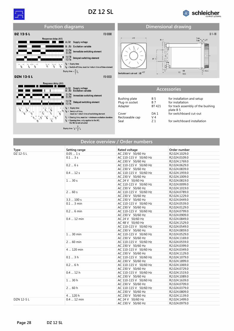
Function diagrams
Dimensional drawing
Accessories Bushing plate Plug-in socket Adapter Cover Recloseable cap Seal
B 5 B 7 BT 421 DA 1 V 4 Z 1
for installation and setup for installation for track assembly of the bushing plate B 5 for switchboard cut-out for switchboard installation
Device overview / Order numbers Type Setting range Rated voltage Order number DZ 12-S L 0.05 … 1 s AC 230 V 50/60 Hz R2.024.1029.0 0.1 … 3 s AC 110-115 V 50/60 Hz R2.024.0109.0 AC 230 V 50/60 Hz R2.024.1769.0 0.2 … 6 s AC 110-115 V 50/60 Hz R2.024.0629.0 AC 230 V 50/60 Hz R2.024.0839.0 0.4 … 12 s AC 110-115 V 50/60 Hz R2.024.1959.0 AC 230 V 50/60 Hz R2.024.1009.0 1 … 30 s AC 24 V 50/60 Hz R2.024.0819.0 AC 110-115 V 50/60 Hz R2.024.0099.0 AC 230 V 50/60 Hz R2.024.1019.0 2 … 60 s AC 110-115 V 50/60 Hz R2.024.0789.0 AC 230 V 50/60 Hz R2.024.1229.0 3.3 … 100 s AC 230 V 50/60 Hz R2.024.0449.0 0.1 … 3 min AC 110-115 V 50/60 Hz R2.024.0539.0 AC 230 V 50/60 Hz R2.024.0129.0 0.2 … 6 min AC 110-115 V 50/60 Hz R2.024.0799.0 AC 230 V 50/60 Hz R2.024.0909.0 0.4 … 12 min AC 24 V 50/60 Hz R2.024.0849.0 AC 48 V 50/60 Hz R2.024.1529.0 AC 110-115 V 50/60 Hz R2.024.0549.0 AC 230 V 50/60 Hz R2.024.0859.0 1 … 30 min AC 110-115 V 50/60 Hz R2.024.0529.0 AC 230 V 50/60 Hz R2.024.1169.0 2 … 60 min AC 110-115 V 50/60 Hz R2.024.0559.0 AC 230 V 50/60 Hz R2.024.0399.0 4 … 120 min AC 110-115 V 50/60 Hz R2.024.0349.0 AC 230 V 50/60 Hz R2.024.1129.0 0.1 … 3 h AC 110-115 V 50/60 Hz R2.024.1079.0 AC 230 V 50/60 Hz R2.024.1899.0 0.2 … 6 h AC 110-115 V 50/60 Hz R2.024.1069.0 AC 230 V 50/60 Hz R2.024.0729.0 0.4 … 12 h AC 110-115 V 50/60 Hz R2.024.1519.0 AC 230 V 50/60 Hz R2.024.1089.0 1 … 30 h AC 110-115 V 50/60 Hz R2.024.1639.0 AC 230 V 50/60 Hz R2.024.0709.0 2 … 60 h AC 110-115 V 50/60 Hz R2.024.0379.0 AC 230 V 50/60 Hz R2.024.0809.0 4 … 120 h AC 230 V 50/60 Hz R2.024.1139.0 DZN 12-S L 0.4 … 12 min AC 24 V 50/60 Hz R2.024.1499.0 AC 230 V 50/60 Hz R2.024.0979.0
DZ 12 - SL
DZ 12 SL Page 29
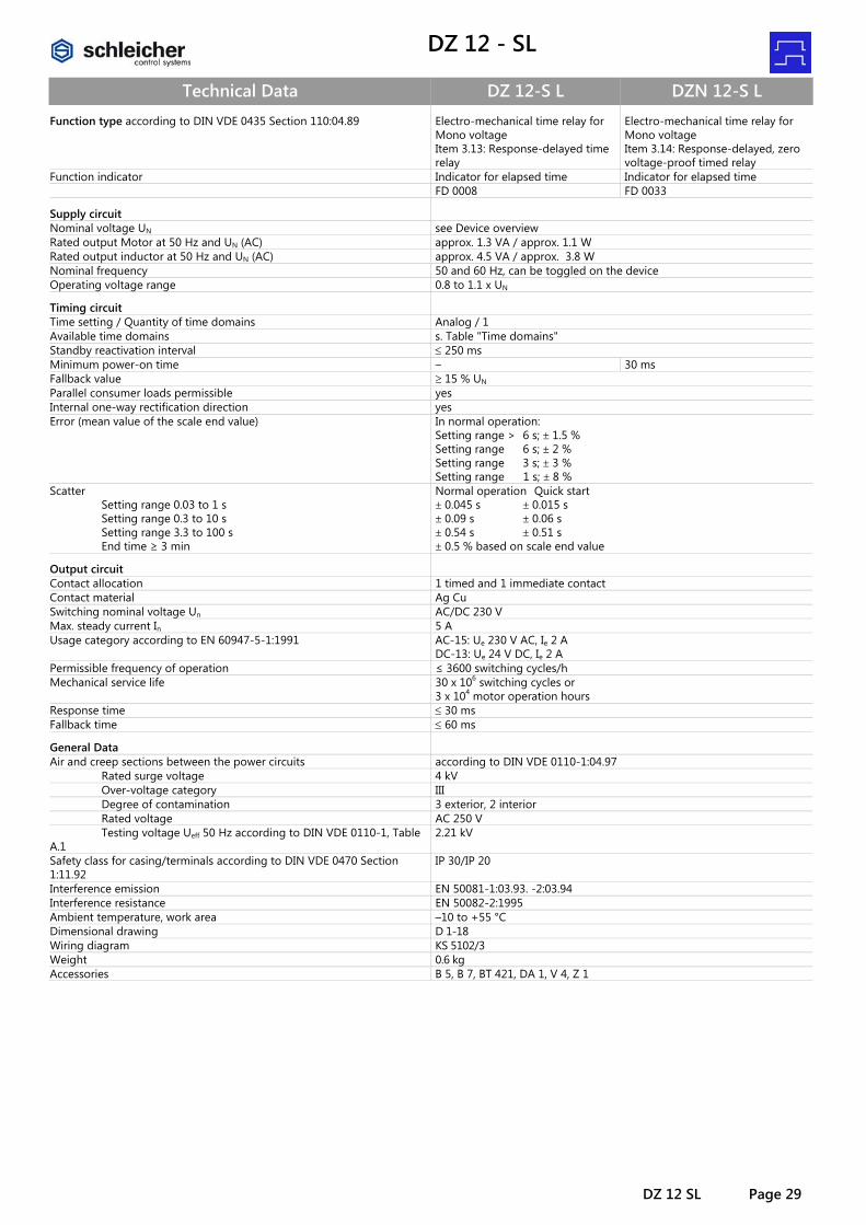
Technical Data DZ 12-S L DZN 12-S L Function type according to DIN VDE 0435 Section 110:04.89 Electro-mechanical time relay for
Mono voltage Item 3.13: Response-delayed time relay
Electro-mechanical time relay for Mono voltage Item 3.14: Response-delayed, zero voltage-proof timed relay
Function indicator Indicator for elapsed time Indicator for elapsed time FD 0008 FD 0033
Supply circuit
Nominal voltage UN see Device overview Rated output Motor at 50 Hz and UN (AC) approx. 1.3 VA / approx. 1.1 W Rated output inductor at 50 Hz and UN (AC) approx. 4.5 VA / approx. 3.8 W Nominal frequency 50 and 60 Hz, can be toggled on the device Operating voltage range 0.8 to 1.1 x UN
Timing circuit
Time setting / Quantity of time domains Analog / 1 Available time domains s. Table "Time domains" Standby reactivation interval ≤ 250 ms Minimum power-on time – 30 ms Fallback value ≥ 15 % UN Parallel consumer loads permissible yes Internal one-way rectification direction yes Error (mean value of the scale end value) In normal operation:
Setting range > 6 s; ± 1.5 % Setting range 6 s; ± 2 % Setting range 3 s; ± 3 % Setting range 1 s; ± 8 %
Scatter Setting range 0.03 to 1 s Setting range 0.3 to 10 s Setting range 3.3 to 100 s End time ≥ 3 min
Normal operation Quick start ± 0.045 s ± 0.015 s ± 0.09 s ± 0.06 s ± 0.54 s ± 0.51 s ± 0.5 % based on scale end value
Output circuit
Contact allocation 1 timed and 1 immediate contact Contact material Ag Cu Switching nominal voltage Un AC/DC 230 V Max. steady current In 5 A Usage category according to EN 60947-5-1:1991 AC-15: Ue 230 V AC, Ie 2 A
DC-13: Ue 24 V DC, Ie 2 A Permissible frequency of operation ≤ 3600 switching cycles/h Mechanical service life 30 x 106 switching cycles or
3 x 10⁴ motor operation hours Response time ≤ 30 ms Fallback time ≤ 60 ms
General Data
Air and creep sections between the power circuits according to DIN VDE 0110-1:04.97 Rated surge voltage 4 kV Over-voltage category III Degree of contamination 3 exterior, 2 interior Rated voltage AC 250 V Testing voltage Ueff 50 Hz according to DIN VDE 0110-1, Table A.1
2.21 kV
Safety class for casing/terminals according to DIN VDE 0470 Section 1:11.92
IP 30/IP 20
Interference emission EN 50081-1:03.93. -2:03.94 Interference resistance EN 50082-2:1995 Ambient temperature, work area –10 to +55 °C Dimensional drawing D 1-18 Wiring diagram KS 5102/3 Weight 0.6 kg Accessories B 5, B 7, BT 421, DA 1, V 4, Z 1

DZA / DZAN 52 / 53 L / SL DZ
Page 30 A / DZAN 52 / 53 L / SL
DZA 52-SL DZA 53-SL
DZAN 52-SL DZA 52 L
Response-delayed multi-domain time relay
• Devices for Mono voltage • Function: response delay (AV), zero voltage-proof at DZAN 52-S L • 1 Setting range subdivided into 6 time domains contact assembly: • DZA 52-S L = 1 timed and 1 immediate contact • DZAN 52-S L = 1 timed and 1 immediate contact • DZA 53-S L = 2 timed contacts and 1 immediate "a" contact • DZA 52 L = 2 timed contacts
72 mm x 72 mm
Wiring diagram
Function (continued) Impulse triggering: To trigger the zero voltage-proof timed relay, an impulse to the coupling suffices - since immediate latching occurs by way of the latch pin (motor and inductor connectors separate). The time elapse begins upon the motor excitation. After triggering the impulse, the immediate contact moves to its working position, at which time elapse has ended. After this time has elapsed, it falls back to the default position. The timed contact opens only for approx. 10 ms. A toggle of the time contacts to the "a" contact side does not transpire. Reset: A mechanical Reset to 0 is possible for these devices. Reset DZAN 52-S L: An electrical and mechanical Reset to 0 is only possi-ble on this device when the mechanical latch is deactivated. If a Reset must take place following an interruption of the time elapse, then the extinguisher lever on the front plate (top right on the front plate) in the direction of the arrow.
Accessories Bushing plate Plug-in socket Adapter Cover Recloseable cap Seal
B 5 or B 9 B 7 or B 8 BT 421 DA 1 V 4 Z 1
for installation and setup for installation for track assembly of the bush-ing plate B 5 for switchboard cut-out for switchboard installation
Time domains Available setting ranges:
0.1 s to 1000 s subdivided into 6 time domains
0.2 s to 60 h subdivided into 6 time domains
0.1 … 3 s 0.2 … 6 s 0.3 … 10 2 … 60 s
1 … 30 s 0.2 … 6 min 3.3 … 100 s 2 … 60 min 10 … 300 s 0.2 … 6 h 33 … 1000 s 2 … 60 h
0.1 s to 30 h subdivided into 6 time domains
0.1 … 3 s 1 … 30 s
0.1 … 3 min 1 … 30 min
0.1 … 3 h 1 … 30 h
General information • The electromechanical timed relays are equipped with a synchronous
motor and magnetic coupling. • The setting of the time domains occurs at the front, via a selector
switch,. The infinitely adjustable time setting within a domain is per-formed with the aid of the transparent knob.
• The time elapse indicator runs during operation from the set time value to 0.
Function Upon the excitation of the motor and the magnet, the immediate con-tact is set to the operating positions, and the time elapse begins. If the preselected time is attained, the time contact is activated and the motor powered off. After the de-excitation, the magnet, the timing element and all contacts move to the default position. If a voltage interruption occurs during the time elapse, then the magnet, the immediate contact and the timing element fall into the default position. For the zero voltage-proof timed relay DZAN 52-S L, the function is as described above; however, during excitation, the magnetic flap is latched shut by a latch pin, so that even in the deenergized state, the already-elapsed time is maintained. The time elapse can be interrupted any number of times. The immediate contact also remains in the operating position during the voltage inter-ruption. If the preselected time has been attained, the latch pin is released, the time contacts are activated and the motor powered off.

DZA / DZAN 52 / 53 L / SL
DZA / DZAN 52 / 53 L / SL Page 31
Function diagrams
Notes • By way of a frequency toggle on the bottom of the casing, the relay
can be adjusted to the respective frequency (50 or 60 Hz). The plant's default setting is 50 Hz.
• The relays have separate motor and magnet connectors. This results in various operation modes: 1. Time addition: Saving already-elapsed times and/or adding differ-
ent time sections by separate actuation of the magnet coupling and the motor.
2. Quick start: Reduction of time scatter to a minimum, by always keeping the motor live (and only the magnet coupling is excited and de-excited after the time elapses). This avoids the motor fault. For elapsed times over 60 s, the quick start no longer affects time scat-ter.
3. Normal operation: Simultaneous excitation and de-excitation of the magnetic coupling and the motor. Recommended for elapsed times over 60 s.
• The largest return precision is attainable by selecting the smallest possible time domain in the multi-domain version.
• The time domain toggle on the devices should only occur in the de-fault position - since otherwise, time errors and faulty toggle of the contacts may occur.
Dimensional drawing
Device overview / Order numbers Type Setting range Rated voltage Order number DZA 52-S L 0.1 s … 1000 s AC 24 V 50/60 Hz R2.027.0219.0 AC 110-115 V 50/60 Hz R2.027.0039.0 AC 125-127 V 50/60 Hz R2.027.0049.0 AC 230 V 50/60 Hz R2.027.0099.0 0.1 s … 30 h AC 24 V 50/60 Hz R2.027.0329.0 AC 110-115 V 50/60 Hz R2.027.0279.0 AC 125-127 V 50/60 Hz R2.027.0309.0 AC 230 V 50/60 Hz R2.027.0079.0 0.2 s … 60 h AC 24 V 50/60 Hz R2.027.0339.0 AC 42 V 50/60 Hz R2.027.0179.0 AC 48 V 50/60 Hz R2.027.0229.0 AC 110-115 V 50/60 Hz R2.027.0259.0 AC 125-127 V 50/60 Hz R2.027.0279.0 AC 230 V 50/60 Hz R2.027.0059.0 DZAN 52-S L 0.1 s … 1000 s AC 24 V 50/60 Hz R2.027.0289.0 AC 110-115 V 50/60 Hz R2.027.0239.0 AC 230 V 50/60 Hz R2.027.0199.0 0.1 s … 30 h AC 24 V 50/60 Hz R2.027.0119.0 AC 110-115 V 50/60 Hz R2.027.0129.0 AC 230 V 50/60 Hz R2.027.0089.0 0.2 s … 60 h AC 24 V 50/60 Hz R2.027.0149.0 AC 110-115 V 50/60 Hz R2.027.0189.0 AC 230 V 50/60 Hz R2.027.0029.0 DZA 53-S L 0.2 s … 60 h AC 230 V 50/60 Hz R2.027.0269.0 DZA 52 L 0.2 s … 60 h AC 24 V 50/60 Hz R2.027.0209.0 AC 110-115 V 50/60 Hz R2.027.0139.0 AC 230 V 50/60 Hz R2.027.0069.0
DZA / DZAN 52 / 53 L / SL DZ
Page 32 A / DZAN 52 / 53 L / SL
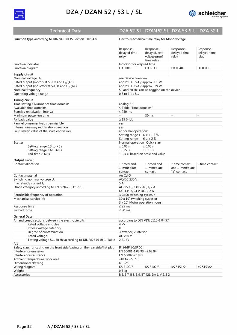
Technical Data DZA 52-S L DZAN 52-S L DZA 53-S L DZA 52 L Function type according to DIN VDE 0435 Section 110:04.89 Electro-mechanical time relay for Mono voltage
Response-
delayed time relay
Response-delayed, zero voltage proof time relay
Response-delayed time relay
Response-delayed time relay
Function indicator Indicator for elapsed time Function diagram FD 0008 FD 0033 FD 0040 FD 0011
Supply circuit
Nominal voltage UN see Device overview Rated output (motor) at 50 Hz and UN (AC) approx. 1.3 VA / approx. 1.1 W Rated output (inductor) at 50 Hz and UN (AC) approx. 1.0 VA / approx. 0.9 W Nominal frequency 50 and 60 Hz, can be toggled on the device Operating voltage range 0.8 to 1.1 x UN
Timing circuit
Time setting / Number of time domains analog / 6 Available time domains s. Table "Time domains" Standby reactivation interval ≤ 250 ms Minimum power-on time – 30 ms – – Fallback value ≥ 15 % UN Parallel consumer loads permissible yes Internal one-way rectification direction yes Fault (mean value of the scale end value) at normal operation:
Setting range > 6 s; ± 1.5 % Setting range 6 s; ± 2 %
Scatter Setting range 0.3 to +6 s Setting range 3 to +60 s End time ≥ 60 s
Normal operation Quick start ± 0.06 s ± 0.03 s ± 0.22 s ± 0.19 s ± 0.3 % based on scale end value
Output circuit
Contact allocation 1 timed and 1 immediate contact
1 timed and 1 immediate contact
2 time contact and 1 immediate "a" contact
2 time contact
Contact material Ag Cd O Switching nominal voltage Un AC/DC 230 V max. steady current In 5 A Usage category according to EN 60947-5-1:1991 AC-15: Ue 230 V AC, Ie 2 A
DC-13: Ue 24 V DC, Ie 2 A Permissible frequency of operation ≤ 3600 switching cycles/h Mechanical service life 30 x 106 switching cycles or
3 x 10⁴ Motor operation hours Response time ≤ 25 ms Fallback time ≤ 80 ms
General Data
Air and creep sections between the electric circuits according to DIN VDE 0110-1:04.97 Rated voltage impulse 4 kV Excess voltage category III Degree of contamination 3 exterior, 2 interior Rated voltage AC 250 V Testing voltage Ueff 50 Hz according to DIN VDE 0110-1, Table A.1
2.21 kV
Safety class for casing on the front side/casing on the rear side/flat plug IP 54/IP 20/IP 00 Interference emission EN 50081-1:03.93. -2:03.94 Interference resistance EN 50082-2:1995 Ambient temperature, work area –10 to +55 °C Dimensional drawing D 1-25 Wiring diagram KS 5102/3 KS 5102/3 KS 5151/2 KS 5153/2 Weight 0.4 kg Accessories B 5, B 7, B 8, B 9, BT 421, DA 1, V 2, Z 2

DZD 92 L
DZD 92 L Page 33
DZD 92 L
Multi-Function - Multi-domain time relay
• Mono voltage • 8 Functions • Setting range 0.05 s to 100 h subdivided into 7 time domains • 1 immediate-action and 1 time contact or 2 time contacts (adjustable)
72 mm x 72 mm
Wiring diagram
Dimensional drawing
Indicators
B1 red LED, lit in presence of the excitation
B2 red LED, lit in presence of the excitation for additive opera-tion
K red LED, lit upon the toggling of the time contact
s; m; h red LEDs for the domain indica-tor; the lit section indicates the set time domain and flashes when the time elapses
3-digit LED indicator for the set target value (and or - during the countdown - indi-cation of the actual value
Time domains Setting range 0.05 s to 100 h subdivided in:
0.05 s … 1 s 3 min … 1 h 0.5 s … 10 s 30 min … 10 h
3 s … 1 min 5 h … 100 h 30 s … 10 min
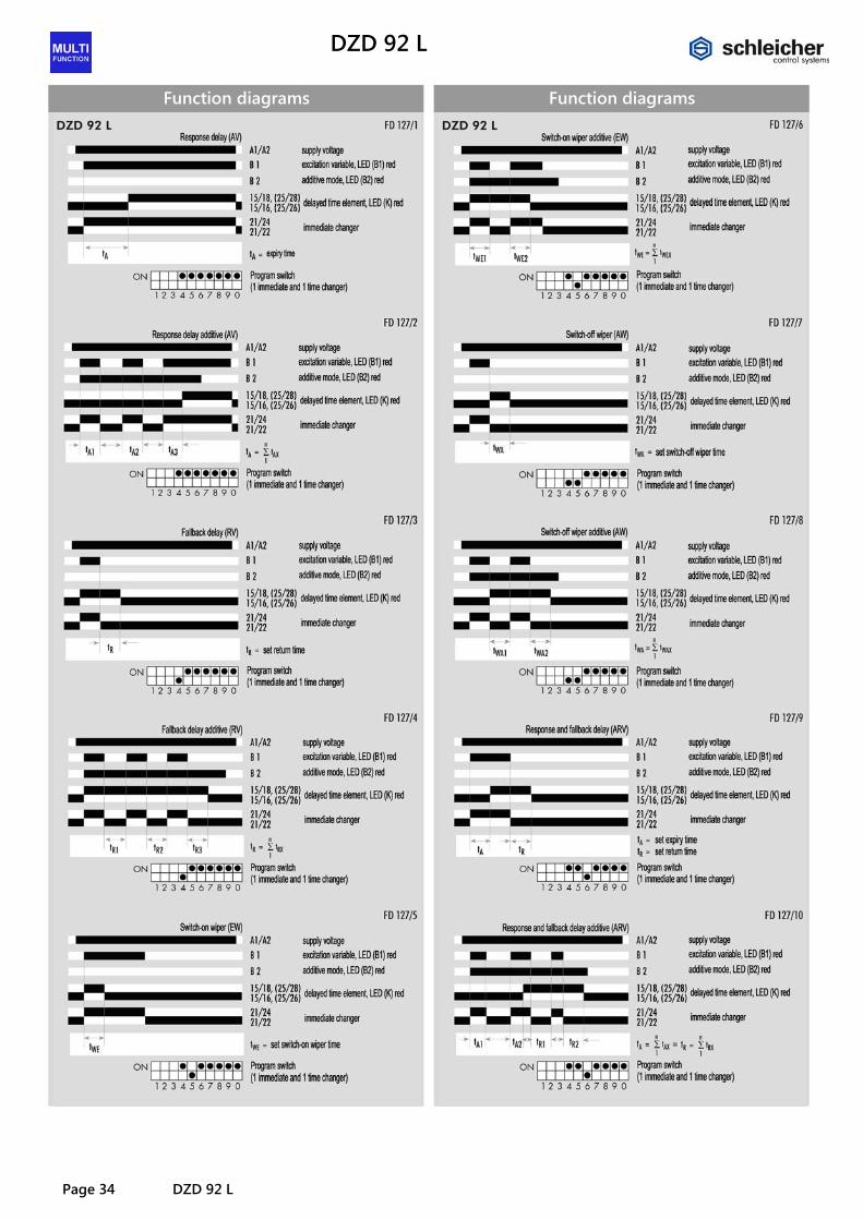
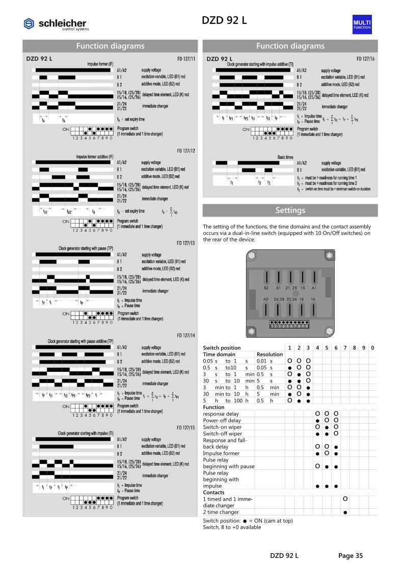
Function The setting of the functions and the time domains as well as the fitting with contacts occurs via a dual in-line switch on the rear of the device (see Settings). The infinitely adjustable time setting within a domain is made with the aid of the transparent knob. The set target value is indicated digitally, with a three-digit (7-Segment) LED indicator. The respective actual value is indicated during the time elapse in analog mode (with 11 LEDs above the scale numbers) and also digitally (with the LED indicator). Functions: • Response delay (AV) • Power-off delay (RV) • Switch-on wiper (EW) • Switch-off wiper (AW) • Response and fallback delay (ARV) • Impulse former (IF) • Pulse relay beginning with pause(TP) • Pulse relay beginning with impulse(TI)
Accessories Bushing plate Plug-in socket Cover Recloseable cap Seal
B 5 B 7 DA 1 V 4 Z 1
for installation and setup for installation for switchboard cut-out for switchboard installation
DZD 92 L
Page 34 DZD 92 L
Function diagrams
Function diagrams
DZD 92 L
DZD 92 L Page 35
Function diagrams
Function diagrams
Settings The setting of the functions, the time domains and the contact assembly occurs via a dual-in-line switch (equipped with 10 On/Off switches) on the rear of the device.
Switch position 1 2 3 4 5 6 7 8 9 0Time domain Resolution 0.05 s to 1 s 0.01 s o o o 0.5 s to10 s 0.05 s • o o 3 s to 1 min 0.5 s o • o 30 s to 10 min 5 s • • o 3 min to 1 h 0.5 min o o • 30 min to 10 h 5 min • o • 5 h to 100 h 0.5 h o • • Function response delay o o o Power-off delay • o o Switch-on wiper o • o Switch-off wiper • • o Response and fall-back delay
o o •
Impulse former • o • Pulse relay beginning with pause
o • •
Pulse relay beginning with impulse
• • •
Contacts 1 timed and 1 imme-diate changer
o
2 time changer • Switch position: • = ON (cam at top) Switch, 8 to +0 available

DZD 92 L
Page 36 DZD 92 L
Technical Data DZD 92 L Function type according to IEC 60050 (445) Analog-adjustable MultiFunction relay for Mono voltage
- Response-delayed time relay - Fallback-delayed time relay with supply voltage - Power- on interval time relay - Power-off interval time relay - Response and fallback delayed time relay - Impulse former - Pulse relay
Function check 6 LED red, 3-digit LED indicator, red, digit height: 7.6 mm
Supply circuit
Nominal voltage UN see Device overview Rated output at 50 Hz and UN (AC) 4.7 VA / 4.6 W Rated output DC 2.6 W Nominal frequency 50 to 60 Hz Operating voltage range 0.8 to 1.1 x UN Nominal current of the energizing quantity (B1) 8 mA
Timing circuit
Time setting/Number of time domains analog/7 Available setting range s. Table "Time domains" Operate time of the energizing quantity (B1) ≤ 20 ms; ≤ 2 ms at 24 V DC Fallback interval of the energizing quantity (B1) ≤ 20 ms; ≤ 3 ms at 24 V DC Standby reactivation interval ≤ 40 / ≤ 60 ms; ≤ 40 / ≤ 10 ms at 24 V DC Minimum power-on time ≤ 40 ms; ≤ 5 ms at 24 V DC Fallback value ≥ 15 % UN Parallel consumer loads permissible yes Internal one-way rectification direction no Mean value of the fault ≤ 1 % ± 10 ms Scatter ≤ ± 0.5 % + ± 10 ms Influence of energizing, supply voltage ≤ 0.005 % / % ∆ UN Influence of the ambient temperature ≤ 0.005 % / K
Output circuit
Contact allocation 1 immediate-action and 1 time changer or 2 time changers Contact material Ag alloy; gold-plated Switching nominal voltage Un 250/300 V AC/DC max. steady current In 5 A Usage category according to EN 60947-5-1:1991 AC-15: Ue 230 V AC, Ie 2 A
DC-13: Ue 24 V DC, Ie 2 A Permissible frequency of operation ≤ 6000 switching cycles/h Mechanical service life 30 x 106 switching cycles Operate time approx. 10 ms Fallback time approx. 10 ms
General Data
Air and creep sections between the electric circuits according to DIN VDE 0110-1:04.97 Rated surge voltage 4 kV Over-voltage category III Degree of contamination 3 exterior, 2 interior Rated voltage 250 V AC Testing voltage Ueff 50 Hz according to DIN VDE 0110-1, Table A.1
2.21 kV
Safety class for casing / terminals according to DIN VDE 0470 Section 1:11.92
IP 30 / IP 20
Interference resistance according to IEC 61000-4 Test acuity 3 Ambient temperature, work area –20 to +60 °C Weight 0.4 kg Accessories B 5, B 7, DA 1, V 4, Z 1 Approvals –
Device overview / Order numbers Type Time delay Rated voltage Order number DZD 92 L s. Table "Time domains" DC 24 V R2.054.0349.1 AC 24 V 50-60 Hz R2.054.0329.1 AC 42 V 50-60 Hz R2.054.0339.1 AC 115 V 50-60 Hz R2.054.0309.1 AC 230 V 50-60 Hz R2.054.0319.1

KPT 11 / 31 KD
KPT 11 / 31 KD Page 37
KPT 11 KD KPT 31 KD
Multi range repeat cycle timer
• Dual voltage • 1 function: KPT 11 KD: repeat cycle starting with OFF (TP) • KPT 31 KD: repeat cycle starting with ON (TI) • Setting range from 0.05 s to 10 h divided into 10 time ranges • 1 change-over contact • 2 LEDs for function display
Circuit diagram
Function diagrams
Dimension diagram
Time ranges Setting range from 0.05 s to 10 h divided into:
0.05 s … 1 s 15 s … 300 s 0.15 s … 3 s 50 s … 1000 s 0.5 s … 10 s 0.05 h … 1 h 1.5 s … 30 s 0.15 h … 3 h
5 s … 100 s 0.5 h … 10 h
Function Different OFF and ON times can be selected in decimal increments on the relay front by means of selector switches. The OFF and ON time within a range is set using the selector wheel. The different supply voltages have to be connected to their respective assigned terminal.
KPT 11 / 31 KD DZ
Page 38 DZD 92 L
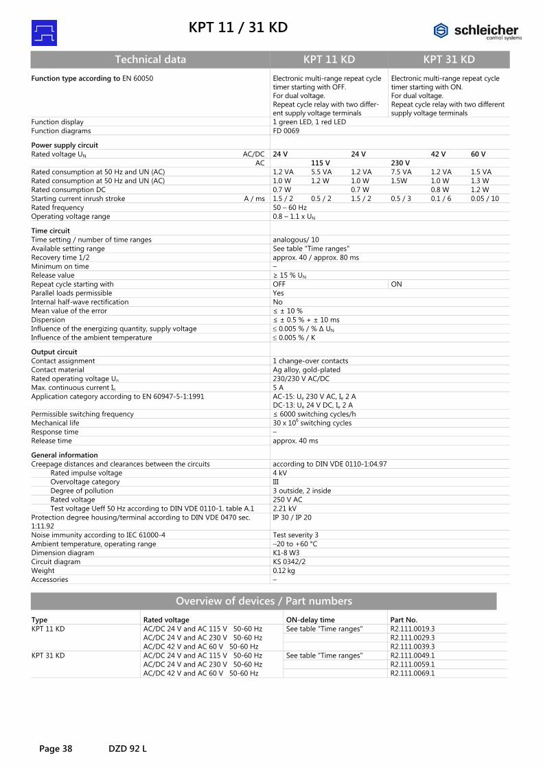
Technical data KPT 11 KD KPT 31 KD Function type according to EN 60050 Electronic multi-range repeat cycle
timer starting with OFF. For dual voltage. Repeat cycle relay with two differ-ent supply voltage terminals
Electronic multi-range repeat cycle timer starting with ON. For dual voltage. Repeat cycle relay with two different supply voltage terminals
Function display 1 green LED, 1 red LED Function diagrams FD 0069
Power supply circuit
Rated voltage UN AC/DC 24 V 24 V 42 V 60 V AC 115 V 230 V Rated consumption at 50 Hz and UN (AC) 1.2 VA 5.5 VA 1.2 VA 7.5 VA 1.2 VA 1.5 VA Rated consumption at 50 Hz and UN (AC) 1.0 W 1.2 W 1.0 W 1.5W 1.0 W 1.3 W Rated consumption DC 0.7 W 0.7 W 0.8 W 1.2 W Starting current inrush stroke A / ms 1.5 / 2 0.5 / 2 1.5 / 2 0.5 / 3 0.1 / 6 0.05 / 10 Rated frequency 50 – 60 Hz Operating voltage range 0.8 – 1.1 x UN
Time circuit
Time setting / number of time ranges analogous/ 10 Available setting range See table "Time ranges" Recovery time 1/2 approx. 40 / approx. 80 ms Minimum on time – Release value ≥ 15 % UN Repeat cycle starting with OFF ON Parallel loads permissible Yes Internal half-wave rectification No Mean value of the error ≤ ± 10 % Dispersion ≤ ± 0.5 % + ± 10 ms Influence of the energizing quantity, supply voltage ≤ 0.005 % / % ∆ UN Influence of the ambient temperature ≤ 0.005 % / K
Output circuit
Contact assignment 1 change-over contacts Contact material Ag alloy, gold-plated Rated operating voltage Un 230/230 V AC/DC Max. continuous current In 5 A Application category according to EN 60947-5-1:1991 AC-15: Ue 230 V AC, Ie 2 A
DC-13: Ue 24 V DC, Ie 2 A Permissible switching frequency ≤ 6000 switching cycles/h Mechanical life 30 x 106 switching cycles Response time – Release time approx. 40 ms
General information
Creepage distances and clearances between the circuits according to DIN VDE 0110-1:04.97 Rated impulse voltage 4 kV Overvoltage category III Degree of pollution 3 outside, 2 inside Rated voltage 250 V AC Test voltage Ueff 50 Hz according to DIN VDE 0110-1. table A.1 2.21 kV Protection degree housing/terminal according to DIN VDE 0470 sec. 1:11.92
IP 30 / IP 20
Noise immunity according to IEC 61000-4 Test severity 3 Ambient temperature, operating range –20 to +60 °C Dimension diagram K1-8 W3 Circuit diagram KS 0342/2 Weight 0.12 kg Accessories –
Overview of devices / Part numbers Type Rated voltage ON-delay time Part No. KPT 11 KD AC/DC 24 V and AC 115 V 50-60 Hz See table "Time ranges" R2.111.0019.3 AC/DC 24 V and AC 230 V 50-60 Hz R2.111.0029.3 AC/DC 42 V and AC 60 V 50-60 Hz R2.111.0039.3 KPT 31 KD AC/DC 24 V and AC 115 V 50-60 Hz See table "Time ranges" R2.111.0049.1 AC/DC 24 V and AC 230 V 50-60 Hz R2.111.0059.1 AC/DC 42 V and AC 60 V 50-60 Hz R2.111.0069.1
KSP 12
KSP 12 Page 39
KSP 12
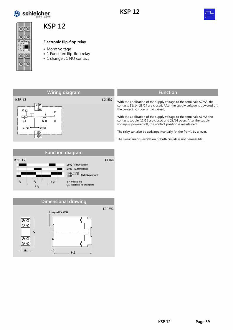
Electronic flip-flop relay
• Mono voltage • 1 Function: flip-flop relay • 1 changer, 1 NO contact
Wiring diagram
Function diagram
Dimensional drawing
Function With the application of the supply voltage to the terminals A2/A3, the contacts 11/14, 23/24 are closed. After the supply voltage is powered off, the contact position is maintained. With the application of the supply voltage to the terminals A1/A3 the contacts toggle, 11/12 are closed and 23/24 open. After the supply voltage is powered off, the contact position is maintained. The relay can also be activated manually (at the front), by a lever. The simultaneous excitation of both circuits is not permissible.
KSP 12
Page 40 KSP 12
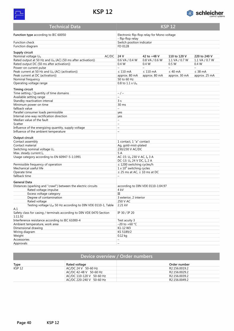
Technical Data KSP 12 Function type according to IEC 60050 Electronic flip-flop relay for Mono voltage
- flip-flop relay Function check Switch position indicator Function diagram FD 0128
Supply circuit
Nominal voltage UN AC/DC 24 V 42 to +48 V 110 to 120 V 220 to 240 V Rated output at 50 Hz and UN (AC) (50 ms after activation)) 0.6 VA / 0.4 W 0.8 VA / 0.6 W 1.1 VA / 0.7 W 1.1 VA / 0.7 W Rated output DC (50 ms after activation)) 0.4 W 0.4 W 0.5 W 0.4 W Power-on current pulse – – – – Peak current at 50 Hz and UN (AC) (activation)) ≤ 110 mA ≤ 110 mA ≤ 40 mA ≤ 38 mA Peak current at DC (activation)) approx. 80 mA approx. 80 mA approx. 30 mA approx. 25 mA Nominal frequency 50 to 60 Hz Operating voltage range 0.8 to 1.1 x UN
Timing circuit
Time setting / Quantity of time domains – / – Available setting range – Standby reactivation interval 3 s Minimum power-on time 30 ms fallback value – Parallel consumer loads permissible yes Internal one-way rectification direction yes Median value of the fault – Scatter – Influence of the energizing quantity, supply voltage – Influence of the ambient temperature –
Output circuit
Contact assembly 1 contact, 1 "a" contact Contact material Ag, gold-mist-plated Switching nominal voltage Un 230/230 V AC/DC Max. steady current In 5 A Usage category according to EN 60947-5-1:1991 AC-15: Ue 230 V AC, Ie 3 A
DC-13: Ue 24 V DC, Ie 2 A Permissible frequency of operation ≤ 1200 switching cycles/h Mechanical useful life 1 x 10⁶ switching cycles Operate time ≤ 25 ms at AC, ≤ 10 ms at DC fallback time –
General Data
Distances (sparking and "crawl") between the electric circuits according to DIN VDE 0110-1:04.97 Rated voltage impulse 4 kV Excess voltage category III Degree of contamination 3 exterior, 2 interior Rated voltage 250 V AC Testing voltage Ueff 50 Hz according to DIN VDE 0110-1, Table A.1
2.21 kV
Safety class for casing / terminals according to DIN VDE 0470 Section 1:11.92
IP 30 / IP 20
Interference resistance according to IEC 61000-4 Test acuity 3 Ambient temperature, work area –20 to +60 °C Dimensional drawing K1-12 W3 Wiring diagram KS 5189/2 Weight 0.12 kg Accessories – Approvals –
Device overview / Order numbers Type Rated voltage Order number KSP 12 AC/DC 24 V 50-60 Hz R2.156.0019.2 AC/DC 42-48 V 50-60 Hz R2.156.0029.2 AC/DC 110-120 V 50-60 Hz R2.156.0039.2 AC/DC 220-240 V 50-60 Hz R2.156.0049.2

KMZ 71 / 72
KMZ 71 / 72 Page 41
KMZ 71 KMZ 72
Multi-function multi-range timer relay
• Multi voltage for AC/DC 24 up to 230 V • 4 functions • Setting range from 0.1 s to 120 h divided into 7 time ranges • KZL 72 = 1 instantaneous and 1 timed change-over contact or
2 timed change-over contacts (selectable) • KZL 71 = 1 timed change-over contact
KZL 72 KZL 71
Circuit diagram
Time ranges Setting range from 0.1 s to 120 h divided into:
0.1 s … 1.2 s 0.1 h … 1.2 h 1 s … 12 s 1 h … 12 h
0.1 min … 1.2 min 10 h … 120 h 1 min … 12 min
General information The functions and time ranges are set on the front through selector switches. Setting of the operating mode Rotate the operating mode selector switch with a screwdriver until the desired operating mode appears in the “MODE” display window. Functions for KZL 72, KZL 71: • A = ON-delay (AV) • B2 = repeat cycle starting with ON (TI) • E = interval ON (EW) • J = one shot (ON-delay) (AI) Setting of the time and time range factor Rotate the time selector switch located in the upper right corner of the control panel to set the desired time (sec., min. or hrs.) The time unit will be shown in the display window over the time selecting wheel. The time range factor (0.1 or 1) is set by rotating the selector switch located in the upper left corner of the operating panel. The selected time range factor will be shown in the display window above the selector switch. Setting of the operating time Use the time selecting wheel (ratio 0 – 12) to set the desired operating time. Setting of the contact assignment The function of the contacts for the model KZL 72 can be selected through a switch located at the bottom of the housing: 2 timed change-over contacts or 1 instantaneous and 1 timed change-over contact.
KMZ72
KMZ71

KMZ 71 / 72
Page 42 KMZ 71 / 72
Function diagrams
Displays and operating components 1 time range switch 2 indicator (orange) (Lit while Time relay output.) 3 Power ON LED (green) (Lit while the Voltage supply.) 4 mode switch 5 only KMZ 72: Switch INIT / TIME
(default setting for timed output) * 6 position for attaching the Users label 7 main command for setting development
time * If you leave the switch between the settings, is a proper operation may not be possible. Pay attention to the correct setting of the switch. Note: The factory setting is mode A and 0.1 s.
Dimension diagram

KMZ 71 / 72
KMZ 71 / 72 Page 43
Technical data KZL 72 KZL 71 Function type according to IEC 60050 (445) Multi-function relay with 4 functions for multi-voltage
– ON-delay timer relay – Interval ON relay – Repeat cycle starting with ON – One shot (ON-delay) relay
Function display 1 LED green, 1 LED orange Function diagrams FD 239-4/10 – 14
Power supply circuit
Rated voltage UN AC/DC 24 – 230 V Rated consumption at 50 Hz and UN 24 V AC 1.1 VA / 0.9 W 0.7 VA / 0.6 W Rated consumption at UN 24 V DC 0.9 W 0.6 W Rated consumption at 50 Hz and UN 230 V AC 2.7 VA / 1.7 W 2.3 VA / 1.4 W Rated consumption at UN 230 V DC 1.4 W 1.4 W Starting current inrush A1/A2 at 24 V DC approx. 250 mA Rated frequency 50 – 60 Hz Operating voltage range 0.85 – 1.1 x UN Release value der Excitation voltage A1/A2 < 8 V AC/DC
Time circuit
Time setting / number of time ranges Analog / 7 Available setting range See table "Time ranges" Recovery time ≥ 100 ms Repeatability ± 1 % + ± 10 ms average value of all measured values Setting tolerance ± 10 % + ± 50 ms Influence of the energizing quantity or supply voltage ± 0.5 % + ± 10 ms Influence of the ambient temperature ± 2 % + ± 10 ms
Output circuit
Contact assignment 1 instantaneous and 1 timed change-over contact or 2 timed change-over contacts
1 timed change-over contact
Contact material AgNi gold-flashed Rated operating voltage Un 230/125 V AC/DC Max. continuous current In 5 A Application category according to EN 60947-5-1:1991 AC-13: Ue 250 V AC, Ie 5 A
DC-13: Ue 24 V DC, Ie 0.1 A AC-15: Ue 250 V AC, Ie 3 A
Permissible switching frequency ≤ 3600 switching cycles/h Mechanical life 10 x 106 switching cycles Electrical life 80 x 104 switching cycles at AC 5 A, 250 V, 360 switching cycles/h
General information
Creepage distances and clearances between the circuits according to DIN VDE 0110-1:04.97 Rated impulse voltage 4 kV Overvoltage category III Degree of pollution 3 outside, 2 inside Rated voltage 250 V AC Test voltage Ueff 50 Hz according to DIN VDE 0110-1, table A.1 2.21 kV Protection degree housing/terminal according to DIN VDE 0470 sec. 1:11.92
IP 30 / IP 20
Noise immunity according to IEC 61000-4 Test severity 3 Ambient temperature, operating range –10 to +55 °C Dimension diagram K1-16 Circuit diagram KS 0328/4 KS 0328/3 Weight 0.12 kg Accessories –
Overview of devices / Part numbers Type Rated voltage ON-delay time Part No. KMZ 71 AC/DC 24-230 V 50-60 Hz See table "Time ranges" R2.066.0019.0 KMZ 72 AC/DC 24-230 V 50-60 Hz See table "Time ranges" R2.066.0029.0

KMZ 91 / 92
Page 44 KMZ 91 / 92
KMZ 92 KMZ 91
Multi-function multi-range timer relay
• Multi voltage for AC/DC 24 up to 230 V • 8 functions • Setting range from 0.1 s to 120 h divided into 7 time ranges • KMZ 92 = 1 instantaneous and 1 timed change-over contact or
2 timed change-over contacts (selectable) • KMZ 91 = 1 timed change-over contact
KZL 92 KZL 91
Circuit diagram
Time ranges Setting range from 0.1 s to 120 h divided into:
0.1 s … 1.2 s 0.1 h … 1.2 h 1 s … 12 s 1 h … 12 h
0.1 min … 1.2 min 10 h … 120 h 1 min … 12 min
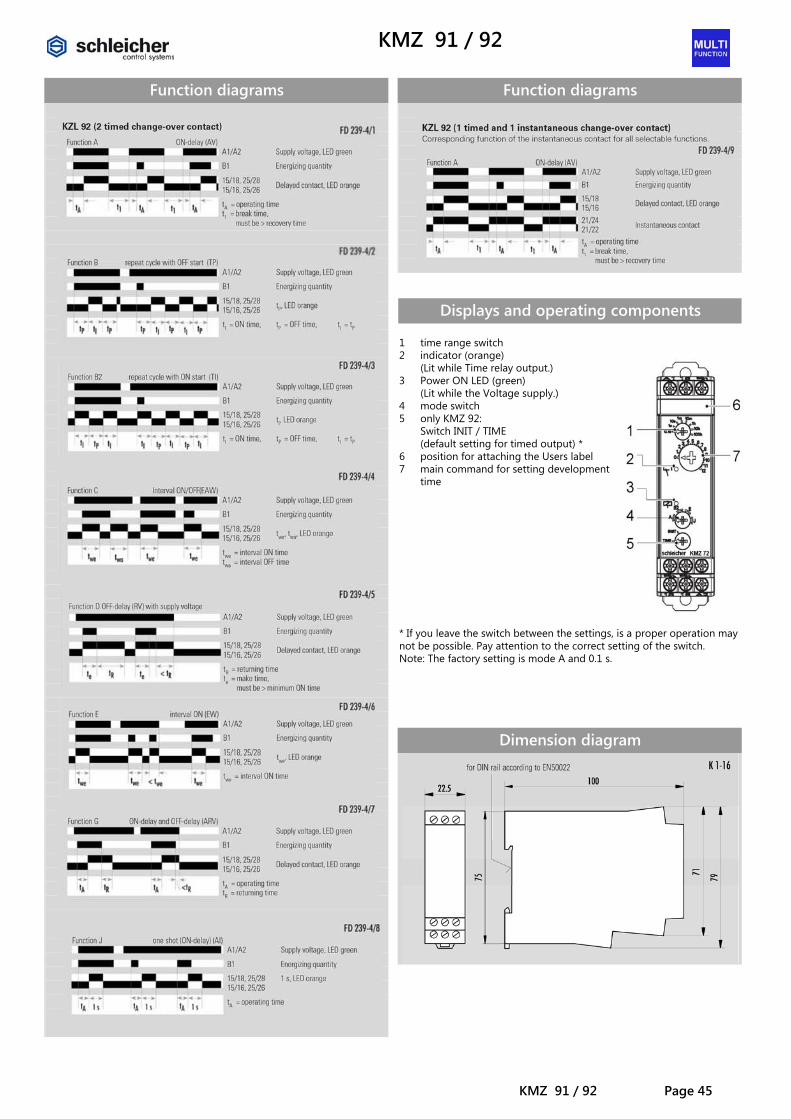
General information The functions and time ranges are set on the front through selector switches. Setting of the operating mode Rotate the operating mode selector switch with a screwdriver until the desired operating mode appears in the “MODE” display window. Functions for KMZ 92, KMZ 91: • A = ON-delay (AV) • B = repeat cycle starting with OFF (TP) • B2 = repeat cycle starting with ON (TI) • C = interval ON/OFF (EAW) • D = OFF-delay (RV) • E = interval ON (EW) • G = ON-delay and OFF-delay (ARV) • J = one shot (ON-delay) (AI) Setting of the time and time range factor Rotate the time selector switch located in the upper right corner of the operating panel to set the desired time (sec., min. or hrs.) The time unit will be shown in the display window over the time selecting wheel. The time range factor (0.1 or 1) is set by rotating the selector switch located in the upper left corner of the operating panel. The selected time range factor will be shown in the display window above the selector switch. Setting of the operating time Use the time selecting wheel (ratio 0 – 12) to set the desired operating time. Setting of the contact assignment The function of the contacts for the model KZL 92 can be selected through a switch located at the bottom of the housing: 2 timed change-over contacts or 1 instantaneous and 1 timed change-over contact.
KMZ92
KMZ91
KMZ 91 / 92
KMZ 91 / 92 Page 45
Function diagrams
Function diagrams
Displays and operating components 1 time range switch 2 indicator (orange) (Lit while Time relay output.) 3 Power ON LED (green) (Lit while the Voltage supply.) 4 mode switch 5 only KMZ 92: Switch INIT / TIME
(default setting for timed output) * 6 position for attaching the Users label 7 main command for setting development
time * If you leave the switch between the settings, is a proper operation may not be possible. Pay attention to the correct setting of the switch. Note: The factory setting is mode A and 0.1 s.
Dimension diagram

KMZ 91 / 92
Page 46 KMZ 91 / 92
Technical data KZL 92 KZL 91 Function type according to IEC 60050 (445)
Multi-function relay with 8 functions for multi-voltage – ON-delay timer relay – OFF-delay timer relay with supply voltage – Interval ON relay – ON-delay and OFF-delay timer relay – Repeat cycle starting with OFF/ON – Interval ON and OFF relay – One shot (ON-delay) relay
Function display 1 LED green, 1 LED orange Function diagrams FD 239-4/1 – 9
Power supply circuit
Rated voltage UN AC/DC 24 – 230 V Rated consumption at 50 Hz and UN 24 V AC 1.1 VA / 0.9 W 0.7 VA / 0.5 W Rated consumption at UN 24 V DC 0.8 W 0.5 W Rated consumption at 50 Hz and UN 230 V AC 2.8 VA / 1.6 W 2.3 VA / 1.5 W Rated consumption at UN 230 V DC 1.6 W 1.4 W Starting current inrush A1/A2 at 24 V DC approx. 250 mA Rated frequency 50 – 60 Hz Operating voltage range 0.85 to 1.1 x UN Rated current B1 - Input at 50 Hz and UN 24 V AC 0.1 mA Rated current B1 - Input at UN 24 V DC 0.2 mA Rated current B1 - Input at 50 Hz and UN 230 V AC 0.8 mA Rated current B1 - Input at UN 230 V DC 1.5 mA Minimum ON time B1 50 ms Excitation voltage B1 High: 20.4 – 253 V AC/DC; Low: 0 – 2.4 V AC/DC Release value of the Excitation voltage B1 < 8 V AC/DC
Time circuit
Time setting / number of time ranges Analog / 7 Available setting range See table "Time ranges" Recovery time ≥ 100 ms Repeatability ± 1 % + ± 10 ms average value of all measured values Setting tolerance ± 10 % + ± 50 ms Influence of the energizing quantity or supply voltage ± 0.5 % + ± 10 ms Influence of the ambient temperature ± 2 % + ± 10 ms
Output circuit
Contact assignment 1 instantaneous and 1 timed change-over contact or 2 timed change-over contacts
1 timed change-over contact
Contact material AgNi gold-flashed Rated operating voltage Un 230/125 V AC/DC Max. continuous current In 5 A Application category according to EN 60947-5-1:1991 AC-13: Ue 250 V AC, Ie 5 A
DC-13: Ue 24 V DC, Ie 0.1 A AC-15: Ue 250 V AC, Ie 3 A
Permissible switching frequency ≤ 3600 switching cycles/h Mechanical life 10 x 106 switching cycles Electrical life 80 x 104 switching cycles at AC 5 A, 250 V, 360 switching cycles/h
General information
Creepage distances and clearances between the circuits according to DIN VDE 0110-1:04.97 Rated impulse voltage 4 kV Overvoltage category III Degree of pollution 2 outside, 2 inside Rated voltage 250 V AC Test voltage Ueff 50 Hz according to DIN VDE 0110-1, table A.1 2.21 kV Protection degree housing/terminal according to DIN VDE 0470 sec. 1:11.92
IP 30 / IP 20
Noise immunity according to IEC 61000-4 Test severity 3 Ambient temperature, operating range –10 to +55 °C Dimension diagram K1-16 Circuit diagram KS 0328/2 KS 0328/1 Weight 0.12 kg Accessories –
Overview of devices / Part numbers Type Rated voltage ON-delay time Part No. KMZ 91 AC/DC 24-230 V 50-60 Hz See table "Time ranges" R2.066.0039.1 KMZ 92 AC/DC 24-230 V 50-60 Hz See table "Time ranges" R2.066.0049.0
KZTH 11
KZTH 11 Page 47
KZTH 11
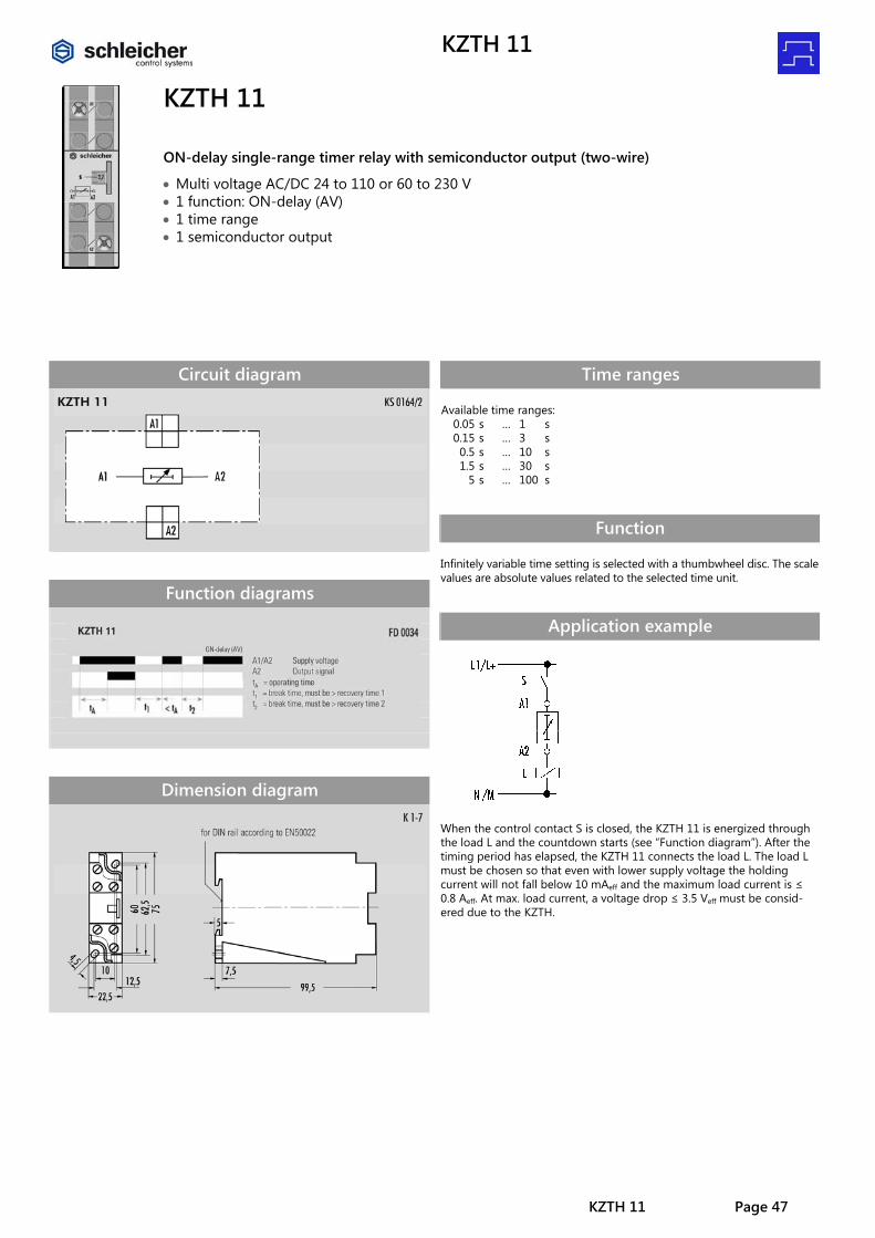
ON-delay single-range timer relay with semiconductor output (two-wire)
• Multi voltage AC/DC 24 to 110 or 60 to 230 V • 1 function: ON-delay (AV) • 1 time range • 1 semiconductor output
Circuit diagram
Function diagrams
Dimension diagram
Time ranges Available time ranges:
0.05 s … 1 s 0.15 s … 3 s 0.5 s … 10 s 1.5 s … 30 s
5 s … 100 s
Function Infinitely variable time setting is selected with a thumbwheel disc. The scale values are absolute values related to the selected time unit.
Application example
When the control contact S is closed, the KZTH 11 is energized through the load L and the countdown starts (see “Function diagram”). After the timing period has elapsed, the KZTH 11 connects the load L. The load L must be chosen so that even with lower supply voltage the holding current will not fall below 10 mAeff and the maximum load current is ≤ 0.8 Aeff. At max. load current, a voltage drop ≤ 3.5 Veff must be consid-ered due to the KZTH.
KZTH 11 DZ
Page 48 KZTH 11
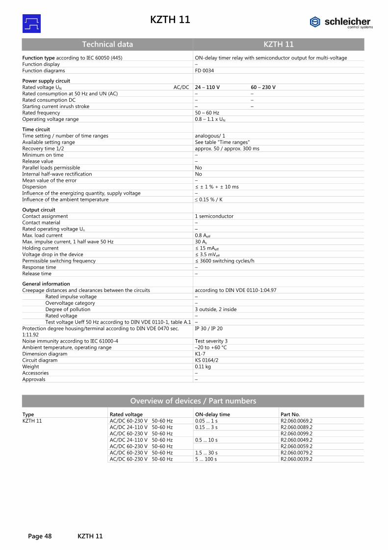
Technical data KZTH 11 Function type according to IEC 60050 (445) ON-delay timer relay with semiconductor output for multi-voltage Function display – Function diagrams FD 0034
Power supply circuit
Rated voltage UN AC/DC 24 – 110 V 60 – 230 V Rated consumption at 50 Hz and UN (AC) – – Rated consumption DC – – Starting current inrush stroke – – Rated frequency 50 – 60 Hz Operating voltage range 0.8 – 1.1 x UN
Time circuit
Time setting / number of time ranges analogous/ 1 Available setting range See table "Time ranges" Recovery time 1/2 approx. 50 / approx. 300 ms Minimum on time – Release value – Parallel loads permissible No Internal half-wave rectification No Mean value of the error – Dispersion ≤ ± 1 % + ± 10 ms Influence of the energizing quantity, supply voltage – Influence of the ambient temperature ≤ 0.15 % / K
Output circuit
Contact assignment 1 semiconductor Contact material – Rated operating voltage Un – Max. load current 0.8 Aeff Max. impulse current, 1 half wave 50 Hz 30 As Holding current ≤ 15 mAeff Voltage drop in the device ≤ 3.5 mVeff Permissible switching frequency ≤ 3600 switching cycles/h Response time – Release time –
General information
Creepage distances and clearances between the circuits according to DIN VDE 0110-1:04.97 Rated impulse voltage – Overvoltage category – Degree of pollution 3 outside, 2 inside Rated voltage – Test voltage Ueff 50 Hz according to DIN VDE 0110-1, table A.1 – Protection degree housing/terminal according to DIN VDE 0470 sec. 1:11.92
IP 30 / IP 20
Noise immunity according to IEC 61000-4 Test severity 3 Ambient temperature, operating range –20 to +60 °C Dimension diagram K1-7 Circuit diagram KS 0164/2 Weight 0.11 kg Accessories – Approvals –
Overview of devices / Part numbers Type Rated voltage ON-delay time Part No. KZTH 11 AC/DC 60-230 V 50-60 Hz 0.05 ... 1 s R2.060.0069.2 AC/DC 24-110 V 50-60 Hz 0.15 ... 3 s R2.060.0089.2 AC/DC 60-230 V 50-60 Hz R2.060.0099.2 AC/DC 24-110 V 50-60 Hz 0.5 ... 10 s R2.060.0049.2 AC/DC 60-230 V 50-60 Hz R2.060.0059.2 AC/DC 60-230 V 50-60 Hz 1.5 ... 30 s R2.060.0079.2 AC/DC 60-230 V 50-60 Hz 5 … 100 s R2.060.0039.2

NGB 12
NGB 12 Page 49
NGB 12
Fixed time flasher relay
• Multi-voltage for AC/DC 24 to 240 V • 1 function: symmetrical flashing, starts OFF • Fixed time 0.5 s / 0.5 s • 2 change-over contact • 2 LEDs for function display
Circuit diagram
Function diagrams
Time ranges Fixed time 0.5 s / 0.5 s
Function ON-delay time The NGB 12 timer relay is available with fixed ON and OFF time. ON time = 0.5 s OFF time = 0.5 s LEDs show the state of the excitation input and the position of the con-tacts. You can monitor the countdown on a flashing LED.
Notes The device is designed for multi-voltage. Phase L1 or L+ must be con-nected to terminal A1; neutral conductor N or M must be connected to terminal A2.
Dimension diagram

NGB 12
Page 50 NGB 12
Technical data NGB 12 Product standard (timer relays) EN 61812-1:1999-08 Function type of the relay according to IEC 60050 445-01-06 Function display 2 LEDs green Function diagrams FD 250-33
Input circuit
Rated voltage A1-A2 AC/DC 24 – 240 V Rated consumption AC 3.5 VA / 1.7 W Rated consumption DC 1.6 W Rated voltage limits 70 – 110 % Rated frequency fn 50 – 60 Hz ± 5 % Release value of the input voltage (power capacity approx. 150 pF/m) ≥ AC/DC 10 V; permissible line capacity 0.2 µF Rated current on control connection (A1) 1 mA Rated consumption on control connection (A1) < 0.25 W Parallel loads permissible A1-A2 yes Internal half-wave rectification A1-A2 no
Time circuit
Time setting / number of time ranges analog / 1 Fixed time Setting ranges for time delay 0.5 s / 0.5 s Cycle start Pause Recovery time 1/2 ≤ 50 / ≤ 50 ms Repeatability (to set value) ≤ ± 0.01 % + ± 10 ms Influence of temperature (within range) ≤ ± 0.002 % Influence of voltage (within range) ≤ ± 0.002 %
Output circuit
Contact assignment 2 change-over contacts Contact material AgNi 90/10 Rated operating voltage AC/DC 24 – 240 V Rated value for limiting continuous current Ith 5 A Minimum contact load ≥ AC/DC 5 V / ≥ 10 mA Application category according to IEC 60947-5-1 AC-15 Ue AC 230 V, Ie 3 A
DC-13 Ue DC 24 V, Ie 2 A Permissible switching frequency ≤ 3600 switching cycles/h Mechanical life 30 x 106 switching cycles Electrical life 20/2 A, AC 250 V, cos ϕ = 0.3 0.12 x 10⁶ switching cycles AC-15 Response time / release time at excitation of A1-A2 40 ms
Other data
Creepage distances and clearances according to IEC 60664-1 Degree of pollution 3 outside, 2 inside Overvoltage category III Rated voltage AC/DC 275 V Degree of protection according to IEC 60529 housing/terminals IP 40 / IP 20 Noise immunity according to IEC 61000-4 Test severity 3 Ambient temperature, operating range -25 – +60 °C Dimension diagram (housing) K 3-2 Circuit diagram of the terminals KS 250-20 Wire ranges stranded or solid stranded with ferrules
1 x 0.2 – 6 or 2 x 0.2 to 2.5 mm2 1 x 0.4 – 4 or 2 x 0.2 to 1.5 mm2
Weight 0.11 kg Accessories –
Overview of devices / Part numbers Type Rated voltage ON-delay time Part No. NGB 12 AC/DC 24-240 V 50-60 Hz 0.5 s / 0.5 s R2.105.0029.0

NGD 31
NGD 31 Page 51
NGD 31
Interval ON star-delta relay
• Multi voltage for AC/DC 24 up to 240 V • 1 function: star-delta switching, interval ON (EW) • 4 time ranges available from 0.1 s to 100 s • 2 normally open contacts • 2 LEDs for function display
Circuit diagram
Function diagrams
Time ranges Available time ranges: <0.1 ... 1 s 0.5 ... 10 s 1.5 ... 30 s 5 ... 100 s
Function Setting the time delay The desired delay time is set with a selecting wheel. It can be set using a screwdriver. Method of operation: The NGD 31 has two sequentially switching de-layed outputs for starting motors in star-delta mode. After expiration of the pre-selected acceleration time tH for the star mode and a fixed transit time tU the second contact switches into the operating position for the delta mode. When the energizing quantity switches off the contact switches into the OFF position. The LEDs shows the switching position of the contacts. The countdown can be monitored on the LEDs.
Notes The device is designed for multi-voltage. Phase L1 or L+ must be con-nected to terminal A1; neutral conductor N or M must be connected to terminal A2. You can change the delay time during operation. The change is effective immediately.
Dimension diagram

NGD 31
Page 52 NGD 31
Technical data NGD 31 Product standard (timer relays) EN 61812-1:1999-08 Function type of the relay according to IEC 60050 445-01-10 + 445-01-08 Function display 2 LEDs green Function diagrams FD 250-44
Input circuit
Rated voltage A1-A2 AC/DC 24 – 240 V Rated consumption AC 3.5 VA / 1.7 W Rated consumption DC 1.6 W Rated voltage limits 70 – 110 % Rated frequency fn 50 – 60 Hz ± 5 % Release value of the input voltage (power capacity approx. 150 pF/m) ≥ AC/DC 10 V; permissible line capacity 0.2 µF Rated current on control connection (A1) 1 mA Rated consumption on control connection (A1) < 0.25 W Parallel loads permissible A1-A2 yes Internal half-wave rectification A1-A2 no
Time circuit
Time setting / number of time ranges analogous/ 1 Setting ranges for time delay See table "Time ranges" Constant fixed transition time 100 ms ≤ ± 2 % Setting tolerance ≤ ± 5 % Repeatability (to set value) ≤ ± 0.01 % + ± 10 ms Influence of temperature (within range) ≤ ± 0.002 % Influence of voltage (within range) ≤ ± 0.002 %
Output circuit
Contact assignment 2 normally open contacts Contact material AgNi 90/10 Rated operating voltage AC/DC 24 – 240 V Rated value for limiting continuous current Ith 5 A Minimum contact load ≥ AC/DC 5 V / ≥ 10 mA Application category according to IEC 60947-5-1 AC-15 Ue AC 230 V, Ie 3 A
DC-13 Ue DC 24 V, Ie 2 A Permissible switching frequency ≤ 3600 switching cycles/h Mechanical life 30 x 106 switching cycles Electrical life 20/2 A, AC 250 V, cos ϕ = 0.3 0.12 x 10⁶ switching cycles AC-15 Response time / release time at excitation of A1-A2 40 ms
Other data
Creepage distances and clearances according to IEC 60664-1 Degree of pollution 3 outside, 2 inside Overvoltage category III Rated voltage AC/DC 275 V Degree of protection according to IEC 60529 housing/terminals IP 40 / IP 20 Noise immunity according to IEC 61000-4 Test severity 3 Ambient temperature, operating range -25 – +60 °C Dimension diagram (housing) K 3-2 Circuit diagram of the terminals KS 250-21 Wire ranges stranded or solid stranded with ferrules
1 x 0.2 – 6 or 2 x 0.2 to 2.5 mm2 1 x 0.4 – 4 or 2 x 0.2 to 1.5 mm2
Weight 0.11 kg Accessories –
Overview of devices / Part numbers Type Rated voltage ON-delay time Part No. NGD 31 AC/DC 24-240 V 50-60 Hz <0.1 ... 1 s R2.062.0039.0 0.5 ... 10 s R2.062.0029.0 1.5 ... 30 s R2.062.0049.0 5 ... 100 s R2.062.0019.0

NGM 1004
NGM 1004 Page 53
NGM 1004
Multi-function multi-range timer relay
• Multi voltage for AC/DC 24 up to 240 V • 10 functions • Setting range from 0.1 s to 300 h divided into 16 selectable time ranges • 1 change-over contact • 2 LEDs for function display
Circuit diagram
Function diagrams See the following pages for the function diagrams
Time ranges Setting range from 0.1 s to 300 h divided into: <0.1 ... 1 s 5 ... 100 s 1.5 ... 30 min 0.5 ... 10 h 0.15 ... 3 s 15 ... 300 s 3 ... 60 min 1.5 ... 30 h 0.5 ... 10 s 50 ... 1000 s 5 ... 100 min 5 ... 100 h 1.5 ... 30 s 0.5 ... 10 min 0.15 ... 3 h 15 ... 300 h
Function Setting the function The function is set with the MODE selector switch and displayed by the function code in the window next to it. The code designation for the function can be found in the column “Function diagrams”. Setting the time delay The time range is set with the RANGE selector switch and displayed in the window next to it. The desired delay time is set with a selecting wheel. LEDs show the state of the excitation input and the position of the con-tacts. You can monitor the countdown on a flashing LED.
Notes • The device is designed for multi-voltage. Connect phase L1 or L+ to
terminal A1 and B1 and neutral N and/or M to terminal A2. • You can change the function or delay time during operation. The change
is effective immediately.
Dimension diagram
NGM 1004
Page 54 NGM 1004
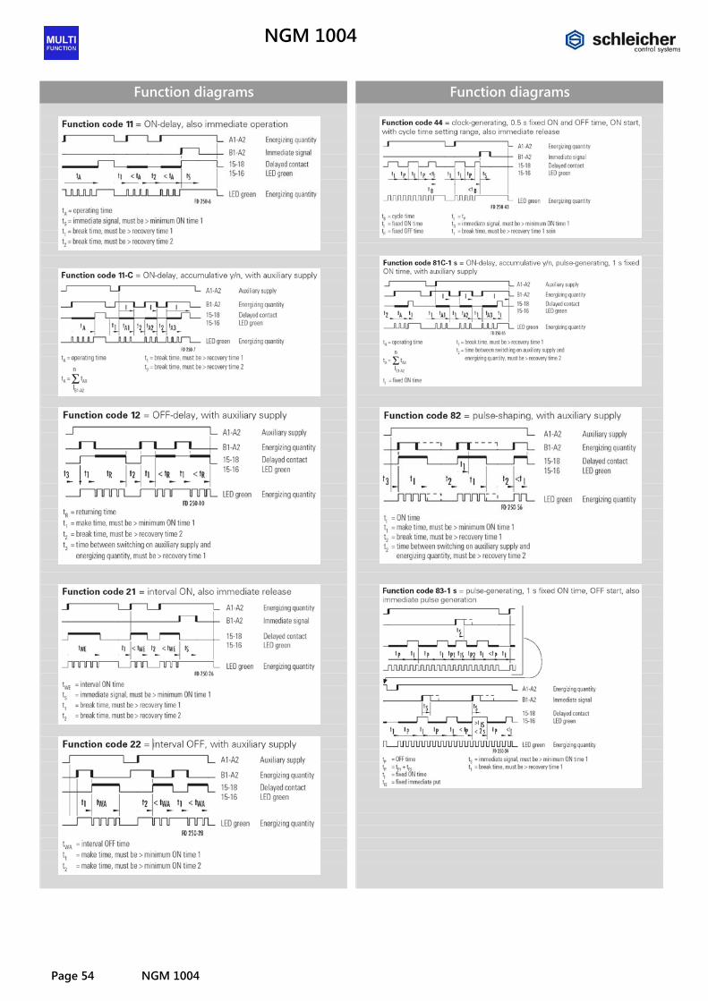
Function diagrams
Function diagrams

NGM 1004
NGM 1004 Page 55
Function diagrams
Function codes / times Function-code
Function-diagram
Recovery time (ms) Minimum ON time (ms)
1 2 3 1 2 11 250-6 ≤ 50 ≤ 50 – ≤ 25 – 11-C 250-7 ≤ 50 ≤ 25 – – – 12 250-10 0 0 – ≤ 25 – 21 250-26 ≤ 50 ≤ 50 – ≤ 25 – 22 250-28 – – – ≤ 25 ≤ 50 44 250-43 ≤ 50 – – ≤ 25 – 81C-1s 250-55 ≤ 50 ≤ 25 0 – – 81C-2s 250-55 ≤ 50 ≤ 25 0 – – 82 250-56 0 0 – ≤ 25 – 83-1s 250-59 ≤ 50 – – ≤ 25 –

NGM 1004
Page 56 NGM 1004
Technical data NGM 1004 Product standard (timer relays) EN 61812-1:1999-08 Relay function according to IEC 60050 (445) Multi-function relay with multi-time range Function display 2 LEDs green Function diagrams See column "Function diagrams"
Input circuit
Rated voltage A1-A2 AC/DC 24 – 240 V Rated consumption AC 3.5 VA / 1.7 W Rated consumption DC 1.6 W Rated voltage limits 70 – 110 % Rated frequency fn 50 – 60 Hz ± 5 % Release value of the input voltage (power capacity approx. 150 pF/m) ≥ AC/DC 10 V; permissible line capacity 0.2 µF Rated current on control connection (B1-A2) 1 mA Rated consumption on control connection (B1-A2) < 0.25 W Parallel loads permissible A1-A2 yes / B1-A2 yes Internal half-wave rectification A1-A2 no / B1-A2 yes
Time circuit
Time setting / number of time ranges analogous/ 16 Setting ranges for time delay See table "Time ranges" Recovery time 1/2/3 See table "Function codes / times" Minimum ON time 1/2 See table "Function codes / times" Setting tolerance ≤ ± 5 % Repeatability (to set value) ≤ ± 0.01 % + ± 10 ms Influence of temperature (within range) ≤ ± 0.002 % Influence of voltage (within range) ≤ ± 0.002 %
Output circuit
Contact assignment 1 change-over contacts Contact material AgNi 90/10 Rated operating voltage AC/DC 24 – 240 V Rated value for limiting continuous current Ith 5 A Minimum contact load ≥ AC/DC 5 V / ≥ 10 mA Application category according to IEC 60947-5-1 AC-15 Ue AC 230 V, Ie 3 A
DC-13 Ue DC 24 V, Ie 2 A Permissible switching frequency ≤ 3600 switching cycles/h Mechanical life 30 x 106 switching cycles Electrical life 20/2 A, AC 250 V, cos ϕ = 0.3 0.12 x 10⁶ switching cycles AC-15 Response time / release time at excitation of A1-A2 40 ms Response time / release time at excitation of B1-A2 20 ms
Other data
Creepage distances and clearances according to IEC 60664-1 Degree of pollution 3 outside, 2 inside Overvoltage category III Rated voltage AC/DC 275 V Degree of protection according to IEC 60529 housing/terminals IP 40 / IP 20 Noise immunity according to IEC 61000-4 Test severity 3 Ambient temperature, operating range -25 – +60 °C Dimension diagram (housing) K 3-1 Circuit diagram of the terminals KS 250-30 Wire ranges stranded or solid stranded with ferrules
1 x 0.2 – 6 or 2 x 0.2 to 2.5 mm2 1 x 0.4 – 4 or 2 x 0.2 to 1.5 mm2
Weight 0.1 kg Accessories –
Overview of devices / Part numbers Type Rated voltage ON-delay time Part No. NGM 1004 AC/DC 24-240 V 50-60 Hz See table "Time ranges" R2.065.0039.0
NGM 1600
NGM 1600 Page 57
NGM 1600
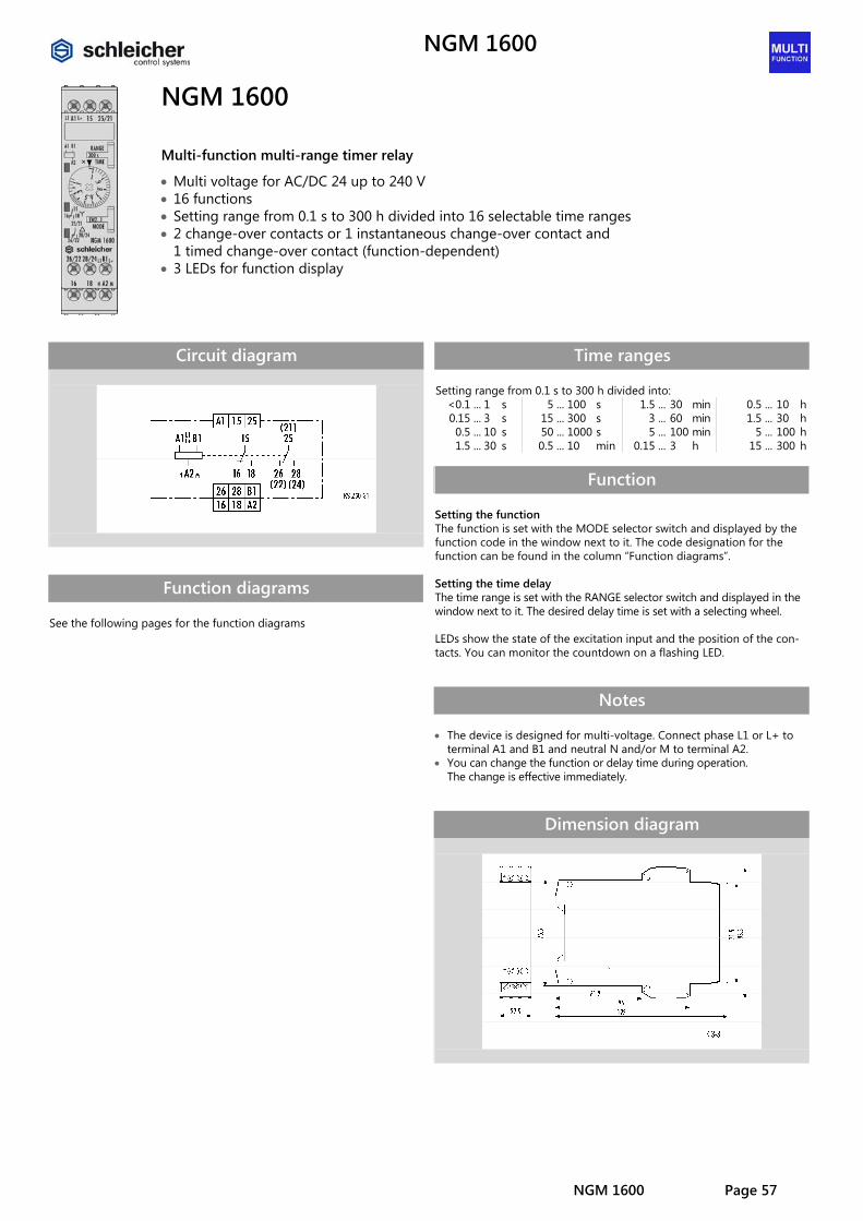
Multi-function multi-range timer relay
• Multi voltage for AC/DC 24 up to 240 V • 16 functions • Setting range from 0.1 s to 300 h divided into 16 selectable time ranges • 2 change-over contacts or 1 instantaneous change-over contact and
1 timed change-over contact (function-dependent) • 3 LEDs for function display
Circuit diagram
Function diagrams See the following pages for the function diagrams
Time ranges Setting range from 0.1 s to 300 h divided into: <0.1 ... 1 s 5 ... 100 s 1.5 ... 30 min 0.5 ... 10 h 0.15 ... 3 s 15 ... 300 s 3 ... 60 min 1.5 ... 30 h 0.5 ... 10 s 50 ... 1000 s 5 ... 100 min 5 ... 100 h 1.5 ... 30 s 0.5 ... 10 min 0.15 ... 3 h 15 ... 300 h
Function Setting the function The function is set with the MODE selector switch and displayed by the function code in the window next to it. The code designation for the function can be found in the column “Function diagrams”. Setting the time delay The time range is set with the RANGE selector switch and displayed in the window next to it. The desired delay time is set with a selecting wheel. LEDs show the state of the excitation input and the position of the con-tacts. You can monitor the countdown on a flashing LED.
Notes • The device is designed for multi-voltage. Connect phase L1 or L+ to
terminal A1 and B1 and neutral N and/or M to terminal A2. • You can change the function or delay time during operation.
The change is effective immediately.
Dimension diagram
NGM 1600
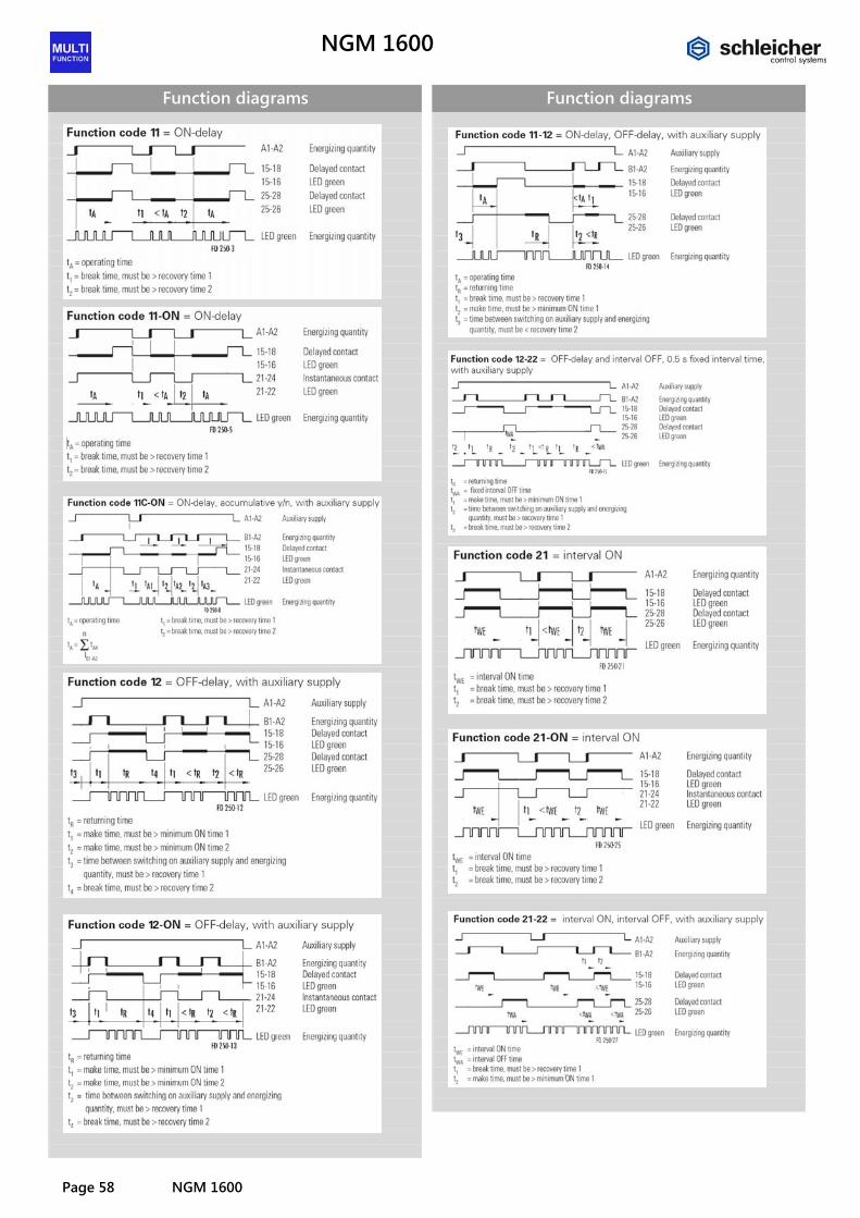
Page 58 NGM 1600
Function diagrams
Function diagrams
NGM 1600
NGM 1600 Page 59
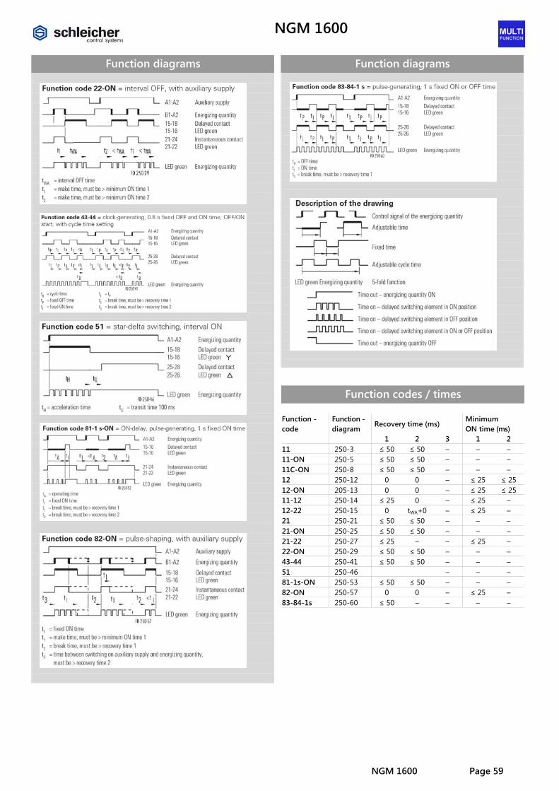
Function diagrams
Function diagrams
Function codes / times Function -code
Function -diagram
Recovery time (ms) Minimum ON time (ms)
1 2 3 1 2 11 250-3 ≤ 50 ≤ 50 – – – 11-ON 250-5 ≤ 50 ≤ 50 – – – 11C-ON 250-8 ≤ 50 ≤ 50 – – – 12 250-12 0 0 – ≤ 25 ≤ 25 12-ON 205-13 0 0 – ≤ 25 ≤ 25 11-12 250-14 ≤ 25 0 – ≤ 25 – 12-22 250-15 0 tWA+0 – ≤ 25 – 21 250-21 ≤ 50 ≤ 50 – – – 21-ON 250-25 ≤ 50 ≤ 50 – – – 21-22 250-27 ≤ 25 – – ≤ 25 – 22-ON 250-29 ≤ 50 ≤ 50 – – – 43-44 250-41 ≤ 50 ≤ 50 – – – 51 250-46 – – – 81-1s-ON 250-53 ≤ 50 ≤ 50 – – – 82-ON 250-57 0 0 – ≤ 25 – 83-84-1s 250-60 ≤ 50 – – – –

NGM 1600
Page 60 NGM 1600
Technical data NGM 1600 Product standard (timer relays) EN 61812-1:1999-08 Relay function according to IEC 60050 (445) Multi-function relay with multi-time range Function display 3 LEDs green Function diagrams See column "Function diagrams"
Input circuit
Rated voltage A1-A2 AC/DC 24 – 240 V Rated consumption AC 3.5 VA / 1.7 W Rated consumption DC 1.6 W Rated voltage limits 70 – 110 % Rated frequency fn 50 – 60 Hz ± 5 % Release value of the input voltage (power capacity approx. 150 pF/m) ≥ AC/DC 10 V; permissible line capacity 0.2 µF Rated current on control connection (B1-A2) 1 mA Rated consumption on control connection (B1-A2) < 0.25 W Parallel loads permissible A1-A2 yes / B1-A2 yes Internal half-wave rectification A1-A2 no / B1-A2 yes
Time circuit
Time setting / number of time ranges analogous/ 16 Setting ranges for time delay See table "Time ranges" Recovery time 1/2/3 See table "Function codes / times" Minimum ON time 1/2 See table "Function codes / times" Setting tolerance ≤ ± 5 % Repeatability (to set value) ≤ ± 0.01 % + ± 10 ms Influence of temperature (within range) ≤ ± 0.002 % Influence of voltage (within range) ≤ ± 0.002 %
Output circuit
Contact assignment 2 change-over contacts Contact material AgNi 90/10 Rated operating voltage AC/DC 24 – 240 V Rated value for limiting continuous current Ith 5 A Minimum contact load ≥ AC/DC 5 V / ≥ 10 mA Application category according to IEC 60947-5-1 AC-15 Ue AC 230 V, Ie 3 A
DC-13 Ue DC 24 V, Ie 2 A Permissible switching frequency ≤ 3600 switching cycles/h Mechanical life 30 x 106 switching cycles Electrical life 20/2 A, AC 250 V, cos ϕ = 0.3 0.12 x 10⁶ switching cycles AC-15 Response time / release time at excitation of A1-A2 40 ms Response time / release time at excitation of B1-A2 20 ms
Other data
Creepage distances and clearances according to IEC 60664-1 Degree of pollution 3 outside, 2 inside Overvoltage category III Rated voltage AC/DC 275 V Degree of protection according to IEC 60529 housing/terminals IP 40 / IP 20 Noise immunity according to IEC 61000-4 Test severity 3 Ambient temperature, operating range –25 to +60 °C Dimension diagram (housing) K 3-3 Circuit diagram of the terminals KS 250-31 Wire ranges stranded or solid stranded with ferrules
1 x 0.2 – 6 or 2 x 0.2 to 2.5 mm2 1 x 0.4 – 4 or 2 x 0.2 to 1.5 mm2
Weight 0.13 kg Accessories –
Overview of devices / Part numbers Type Rated voltage ON-delay time Part No. NGM 1600 AC/DC 24-240 V 50-60 Hz See table "Time ranges" R2.065.0040.0
NGS 12
NGS 12 Page 61
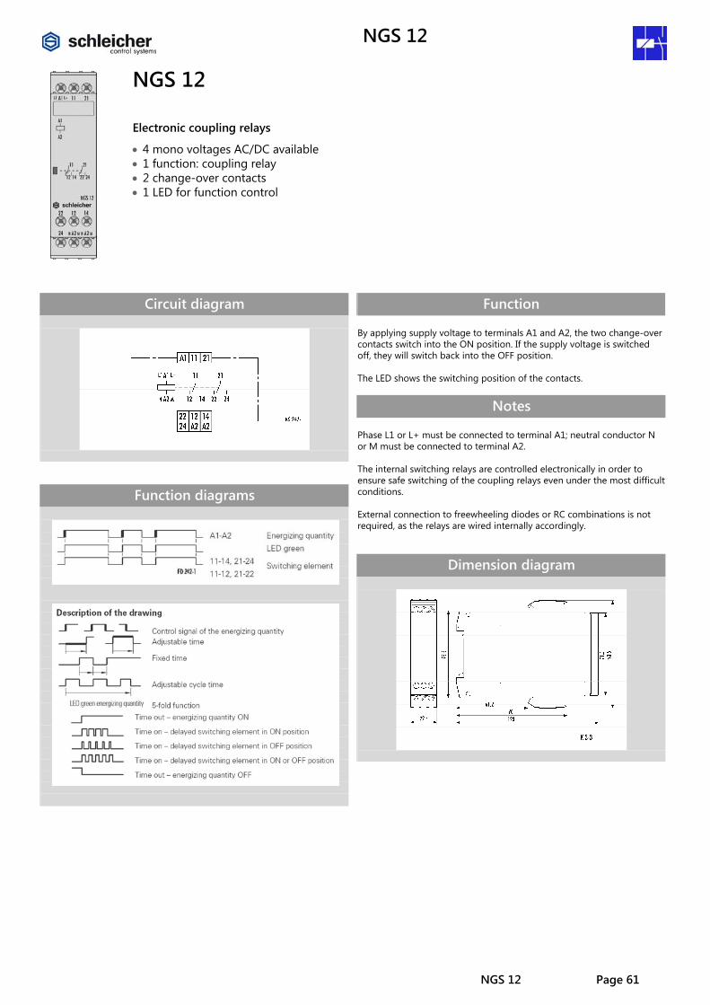
NGS 12
Electronic coupling relays
• 4 mono voltages AC/DC available • 1 function: coupling relay • 2 change-over contacts • 1 LED for function control
Circuit diagram
Function diagrams
Function By applying supply voltage to terminals A1 and A2, the two change-over contacts switch into the ON position. If the supply voltage is switched off, they will switch back into the OFF position. The LED shows the switching position of the contacts.
Notes Phase L1 or L+ must be connected to terminal A1; neutral conductor N or M must be connected to terminal A2. The internal switching relays are controlled electronically in order to ensure safe switching of the coupling relays even under the most difficult conditions. External connection to freewheeling diodes or RC combinations is not required, as the relays are wired internally accordingly.
Dimension diagram

NGS 12
Page 62 NGS 12
Technical data NGS 12 Product standard EN 618122-1:1999-08 Function type according to IEC 60050 Item 2.1: switching relays Function display 1 LED green Function diagrams FD 242-1
Input circuit
AC/DC AC/DC AC/DC AC/DC Rated voltage UN 24 V 28 V 110-127 V 220-240 V Rated consumption at 50 Hz 1.1 VA / 1.0 W 1.2 VA / 1.0 W 1.7 VA / 1.4 W 1.9 VA / 1.6 W Rated consumption at 60 Hz 1.1 VA / 1.0 W 1.2 VA / 1.0 W 1.7 VA / 1.4 W 2.0 VA / 1.7 W Rated consumption DC 1.0 W 1.1 W 1.1 W 1.6 W Switch-on peak 0.3 A / 0.5 ms 0.3 A / 0.5 ms 0.3 A / 0.2 ms 0.2 A / 0.1 ms Rated voltage limits 80 – 110 % Rated frequency fn 50 – 60 Hz ± 5 % Release value of the input voltage (power capacity approx. 150 pF/m) ≥ 15 % UN; permissible line capacity 0.2 µF Parallel loads permissible A1-A2 yes Internal half-wave rectification A1-A2 no
Output circuit
Contact assignment 2 change-over contacts Contact material Ag with 2 to 5 μm Au Rated operating voltage AC/DC 250 V Rated value for limiting continuous current Ith 5 A Minimum contact voltage AC/DC 15 V Application category according to IEC 60947-5-1 AC-15 Ue AC 230 V, Ie 3 A
DC-13 Ue DC 24 V, Ie 2 A Permissible switching frequency ≤ 3600 switching cycles/h Mechanical life 30 x 106 switching cycles Electrical life 20/2 A, AC 250 V, cos ϕ = 0.3 0.12 x 10⁶ switching cycles AC-15 Response time / release time at excitation of A1-A2 10 ms / 13 ms
Other data
Creepage distances and clearances according to IEC 60664-1 Degree of pollution 3 outside, 2 inside Overvoltage category III Rated voltage 250 V Degree of protection according to IEC 60529 housing/terminals IP 40 / IP 20 Ambient temperature, operating range -25 – +60 °C Dimension diagram (housing) K 3-3 Circuit diagram of the terminals KS 242-1 Wire ranges stranded or solid stranded with ferrules
1 x 0.2 – 6 or 2 x 0.2 to 2.5 mm2 1 x 0.4 – 4 or 2 x 0.2 to 1.5 mm2
Weight 0.12 kg Accessories – Approvals –
Overview of devices / Part numbers Type Rated voltage ON-delay time Part No. NGS 12 AC/DC 24 V 50-60 Hz – R2.154.0039.0 AC/DC 28 V 50-60 Hz – R2.154.0049.0 AC/DC 220-240 V 50-60 Hz – R2.154.0029.0 AC 110-127 V 50-60 Hz – R2.154.0019.0
NGZ 11
Subject to change without further notice NGZ 11 Page 63
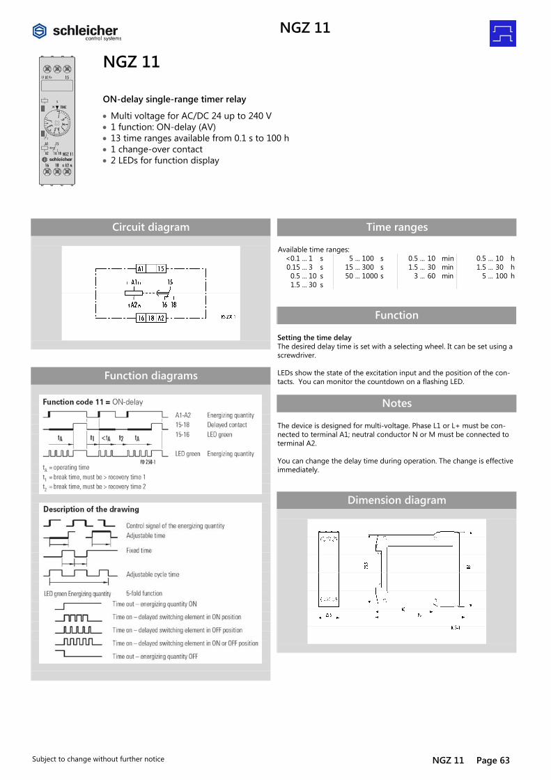
NGZ 11
ON-delay single-range timer relay
• Multi voltage for AC/DC 24 up to 240 V • 1 function: ON-delay (AV) • 13 time ranges available from 0.1 s to 100 h • 1 change-over contact • 2 LEDs for function display
Circuit diagram
Function diagrams
Time ranges Available time ranges: <0.1 ... 1 s 5 ... 100 s 0.5 ... 10 min 0.5 ... 10 h 0.15 ... 3 s 15 ... 300 s 1.5 ... 30 min 1.5 ... 30 h 0.5 ... 10 s 50 ... 1000 s 3 ... 60 min 5 ... 100 h 1.5 ... 30 s
Function Setting the time delay The desired delay time is set with a selecting wheel. It can be set using a screwdriver. LEDs show the state of the excitation input and the position of the con-tacts. You can monitor the countdown on a flashing LED.
Notes The device is designed for multi-voltage. Phase L1 or L+ must be con-nected to terminal A1; neutral conductor N or M must be connected to terminal A2. You can change the delay time during operation. The change is effective immediately.
Dimension diagram

NGZ 11
Page 64 NGZ 11 Subject to change without further notice
Technical data NGZ 11 Product standard (timer relays) EN 61812-1:1999-08 Function type of the relay according to IEC 60050 445-01-02 Function display 2 LEDs green Function diagrams FD 250-1
Input circuit
Rated voltage A1-A2 AC/DC 24 – 240 V Rated consumption AC 3.5 VA / 1.7 W Rated consumption DC 1.6 W Rated voltage limits 70 – 110 % Rated frequency fn 50 – 60 Hz ± 5 % Release value of the input voltage (power capacity approx. 150 pF/m) ≥ AC/DC 10 V; permissible line capacity 0.2 µF Rated current on control connection (A1) 1 mA Rated consumption on control connection (A1) < 0,25 W Parallel loads permissible A1-A2 yes Internal half-wave rectification A1-A2 no
Time circuit
Time setting / number of time ranges analogous/ 1 Setting ranges for time delay See table "Time ranges" Recovery time 1/2 ≤ 50 / ≤ 50 ms Minimum ON time 1/2 – / – ms Setting tolerance ≤ ± 5 % Repeatability (to set value) ≤ ± 0,01 % + ± 10 ms Influence of temperature (within range) ≤ ± 0,002 % Influence of voltage (within range) ≤ ± 0,002 %
Output circuit
Contact assignment 1 change-over contacts Contact material AgNi 90/10 Rated operating voltage AC/DC 24 – 240 V Rated value for limiting continuous current Ith 5 A Minimum contact load ≥ AC/DC 5 V / ≥ 10 mA Application category according to IEC 60947-5-1 AC-15 Ue AC 230 V, Ie 3 A
DC-13 Ue DC 24 V, Ie 2 A Permissible switching frequency ≤ 3600 switching cycles/h Mechanical life 30 x 106 switching cycles Electrical life 20/2 A, AC 250 V, cos ϕ = 0.3 0.12 x 10⁶ switching cycles AC-15 Response time / release time at excitation of A1-A2 40 ms
Other data
Creepage distances and clearances according to IEC 60664-1 Degree of pollution 3 outside, 2 inside Overvoltage category III Rated voltage AC/DC 275 V Degree of protection according to IEC 60529 housing/terminals IP 40 / IP 20 Noise immunity according to IEC 61000-4 Test severity 3 Ambient temperature, operating range -25 – +60 °C Dimension diagram (housing) K 3-1 Circuit diagram of the terminals KS 250-1 Wire ranges stranded or solid stranded with ferrules
1 x 0.2 – 6 or 2 x 0.2 to 2.5 mm2 1 x 0.4 – 4 or 2 x 0.2 to 1.5 mm2
Weight 0.1 kg Accessories –
Overview of devices / Part numbers Type Rated voltage ON-delay time Part No. NGZ 11 AC/DC 24-240 V 50-60 Hz <0.1 ... 1 s R2.064.0079.0 0.15 ... 3 s R2.064.0129.0 0.5 ... 10 s R2.064.0069.0 1.5 ... 30 s R2.064.0119.0 5 ... 100 s R2.064.0079.0 15 ... 300 s R2.064.0039.0 50 ... 1000 s R2.064.0019.0 0.5 ... 10 min R2.064.0059.0 1.5 ... 30 min R2.064.0109.0 3 ... 60 min R2.064.0139.0 0.5 ... 10 h R2.064.0049.0 1.5 ... 30 h R2.064.0099.0 5 ... 100 h R2.064.0029.0
NGZ 12
Subject to change without further notice NGZ 12 Page 65
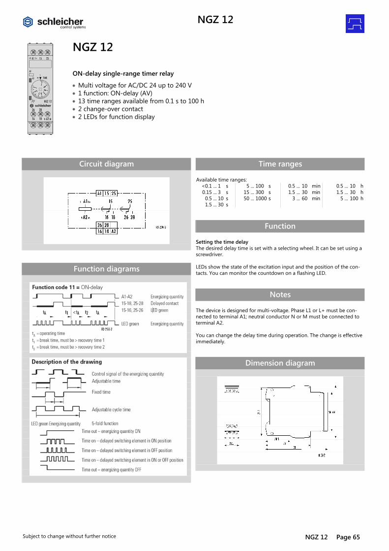
NGZ 12
ON-delay single-range timer relay
• Multi voltage for AC/DC 24 up to 240 V • 1 function: ON-delay (AV) • 13 time ranges available from 0.1 s to 100 h • 2 change-over contact • 2 LEDs for function display
Circuit diagram
Function diagrams
Time ranges Available time ranges: <0.1 ... 1 s 5 ... 100 s 0.5 ... 10 min 0.5 ... 10 h 0.15 ... 3 s 15 ... 300 s 1.5 ... 30 min 1.5 ... 30 h 0.5 ... 10 s 50 ... 1000 s 3 ... 60 min 5 ... 100 h 1.5 ... 30 s
Function Setting the time delay The desired delay time is set with a selecting wheel. It can be set using a screwdriver. LEDs show the state of the excitation input and the position of the con-tacts. You can monitor the countdown on a flashing LED.
Notes The device is designed for multi-voltage. Phase L1 or L+ must be con-nected to terminal A1; neutral conductor N or M must be connected to terminal A2. You can change the delay time during operation. The change is effective immediately.
Dimension diagram
NGZ 12
Page 66 NGZ 12 Subject to change without further notice
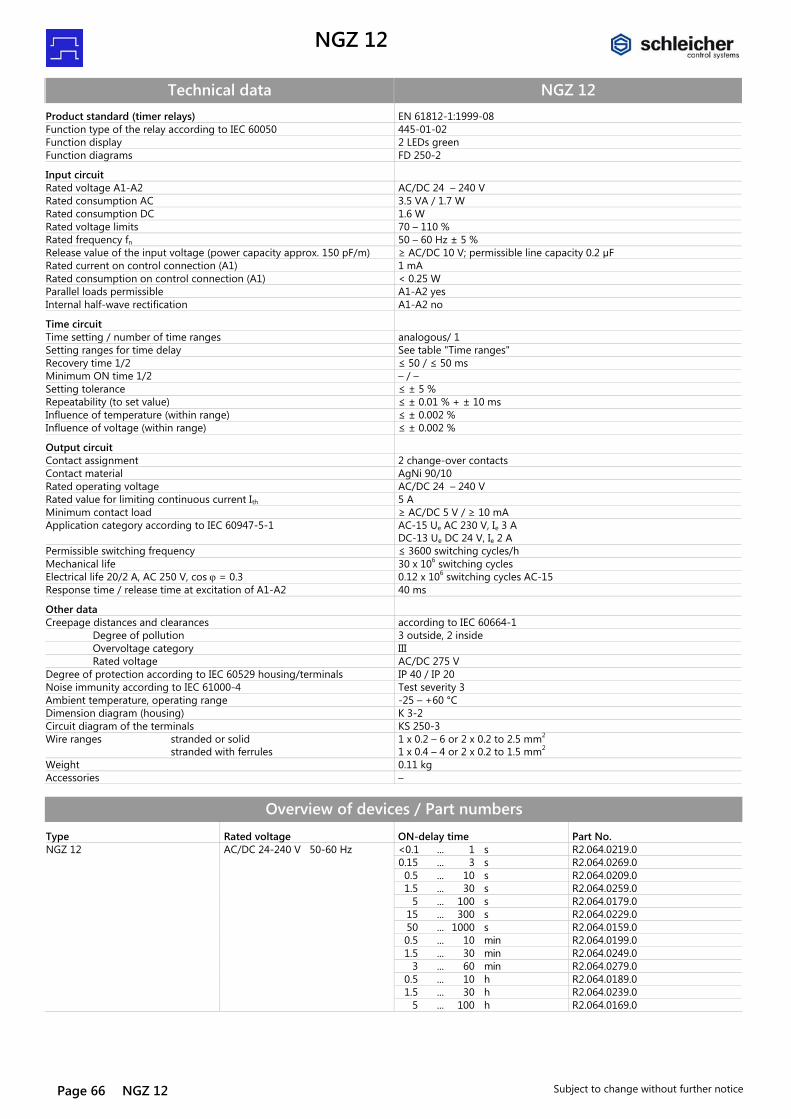
Technical data NGZ 12 Product standard (timer relays) EN 61812-1:1999-08 Function type of the relay according to IEC 60050 445-01-02 Function display 2 LEDs green Function diagrams FD 250-2
Input circuit
Rated voltage A1-A2 AC/DC 24 – 240 V Rated consumption AC 3.5 VA / 1.7 W Rated consumption DC 1.6 W Rated voltage limits 70 – 110 % Rated frequency fn 50 – 60 Hz ± 5 % Release value of the input voltage (power capacity approx. 150 pF/m) ≥ AC/DC 10 V; permissible line capacity 0.2 µF Rated current on control connection (A1) 1 mA Rated consumption on control connection (A1) < 0.25 W Parallel loads permissible A1-A2 yes Internal half-wave rectification A1-A2 no
Time circuit
Time setting / number of time ranges analogous/ 1 Setting ranges for time delay See table "Time ranges" Recovery time 1/2 ≤ 50 / ≤ 50 ms Minimum ON time 1/2 – / – Setting tolerance ≤ ± 5 % Repeatability (to set value) ≤ ± 0.01 % + ± 10 ms Influence of temperature (within range) ≤ ± 0.002 % Influence of voltage (within range) ≤ ± 0.002 %
Output circuit
Contact assignment 2 change-over contacts Contact material AgNi 90/10 Rated operating voltage AC/DC 24 – 240 V Rated value for limiting continuous current Ith 5 A Minimum contact load ≥ AC/DC 5 V / ≥ 10 mA Application category according to IEC 60947-5-1 AC-15 Ue AC 230 V, Ie 3 A
DC-13 Ue DC 24 V, Ie 2 A Permissible switching frequency ≤ 3600 switching cycles/h Mechanical life 30 x 106 switching cycles Electrical life 20/2 A, AC 250 V, cos ϕ = 0.3 0.12 x 10⁶ switching cycles AC-15 Response time / release time at excitation of A1-A2 40 ms
Other data
Creepage distances and clearances according to IEC 60664-1 Degree of pollution 3 outside, 2 inside Overvoltage category III Rated voltage AC/DC 275 V Degree of protection according to IEC 60529 housing/terminals IP 40 / IP 20 Noise immunity according to IEC 61000-4 Test severity 3 Ambient temperature, operating range -25 – +60 °C Dimension diagram (housing) K 3-2 Circuit diagram of the terminals KS 250-3 Wire ranges stranded or solid stranded with ferrules
1 x 0.2 – 6 or 2 x 0.2 to 2.5 mm2 1 x 0.4 – 4 or 2 x 0.2 to 1.5 mm2
Weight 0.11 kg Accessories –
Overview of devices / Part numbers Type Rated voltage ON-delay time Part No. NGZ 12 AC/DC 24-240 V 50-60 Hz <0.1 ... 1 s R2.064.0219.0 0.15 ... 3 s R2.064.0269.0 0.5 ... 10 s R2.064.0209.0 1.5 ... 30 s R2.064.0259.0 5 ... 100 s R2.064.0179.0 15 ... 300 s R2.064.0229.0 50 ... 1000 s R2.064.0159.0 0.5 ... 10 min R2.064.0199.0 1.5 ... 30 min R2.064.0249.0 3 ... 60 min R2.064.0279.0 0.5 ... 10 h R2.064.0189.0 1.5 ... 30 h R2.064.0239.0 5 ... 100 h R2.064.0169.0
NGZ 12 S
Subject to change without further notice NGZ 12 S Page 67
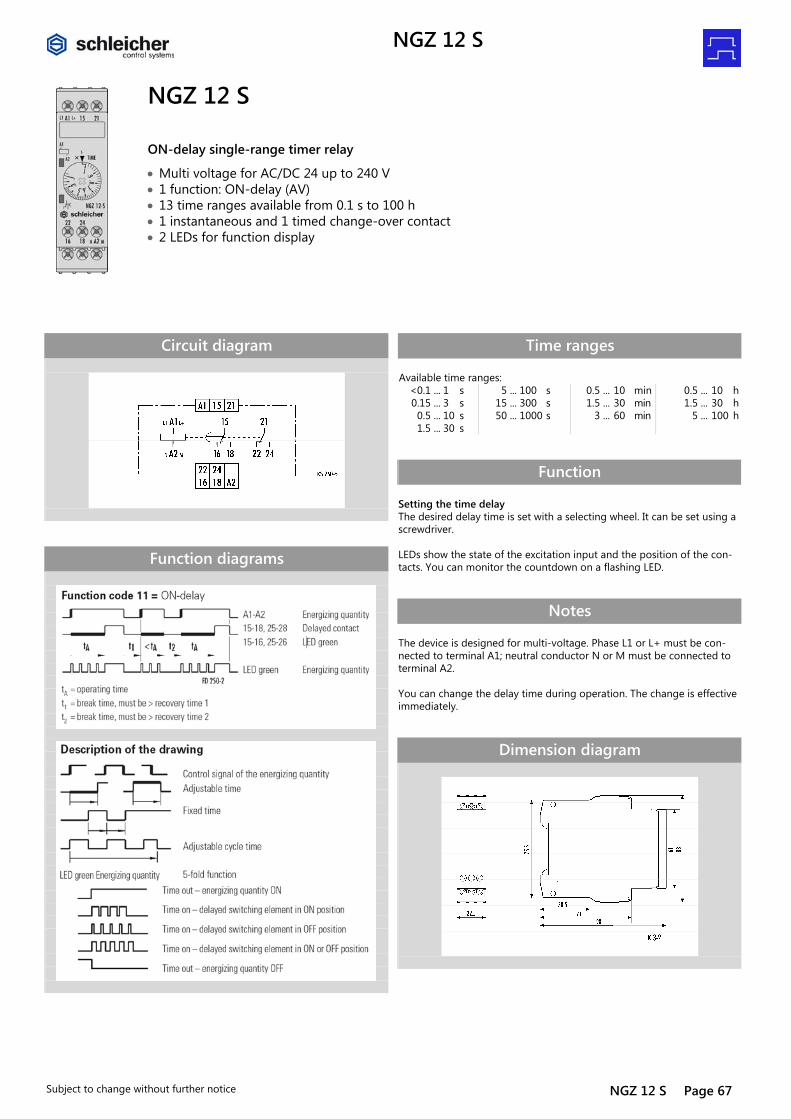
NGZ 12 S
ON-delay single-range timer relay
• Multi voltage for AC/DC 24 up to 240 V • 1 function: ON-delay (AV) • 13 time ranges available from 0.1 s to 100 h • 1 instantaneous and 1 timed change-over contact • 2 LEDs for function display
Circuit diagram
Function diagrams
Time ranges Available time ranges: <0.1 ... 1 s 5 ... 100 s 0.5 ... 10 min 0.5 ... 10 h 0.15 ... 3 s 15 ... 300 s 1.5 ... 30 min 1.5 ... 30 h 0.5 ... 10 s 50 ... 1000 s 3 ... 60 min 5 ... 100 h 1.5 ... 30 s
Function Setting the time delay The desired delay time is set with a selecting wheel. It can be set using a screwdriver. LEDs show the state of the excitation input and the position of the con-tacts. You can monitor the countdown on a flashing LED.
Notes The device is designed for multi-voltage. Phase L1 or L+ must be con-nected to terminal A1; neutral conductor N or M must be connected to terminal A2. You can change the delay time during operation. The change is effective immediately.
Dimension diagram
NGZ 12 S DZ
Page 68 NGZ 12 S Subject to change without further notice
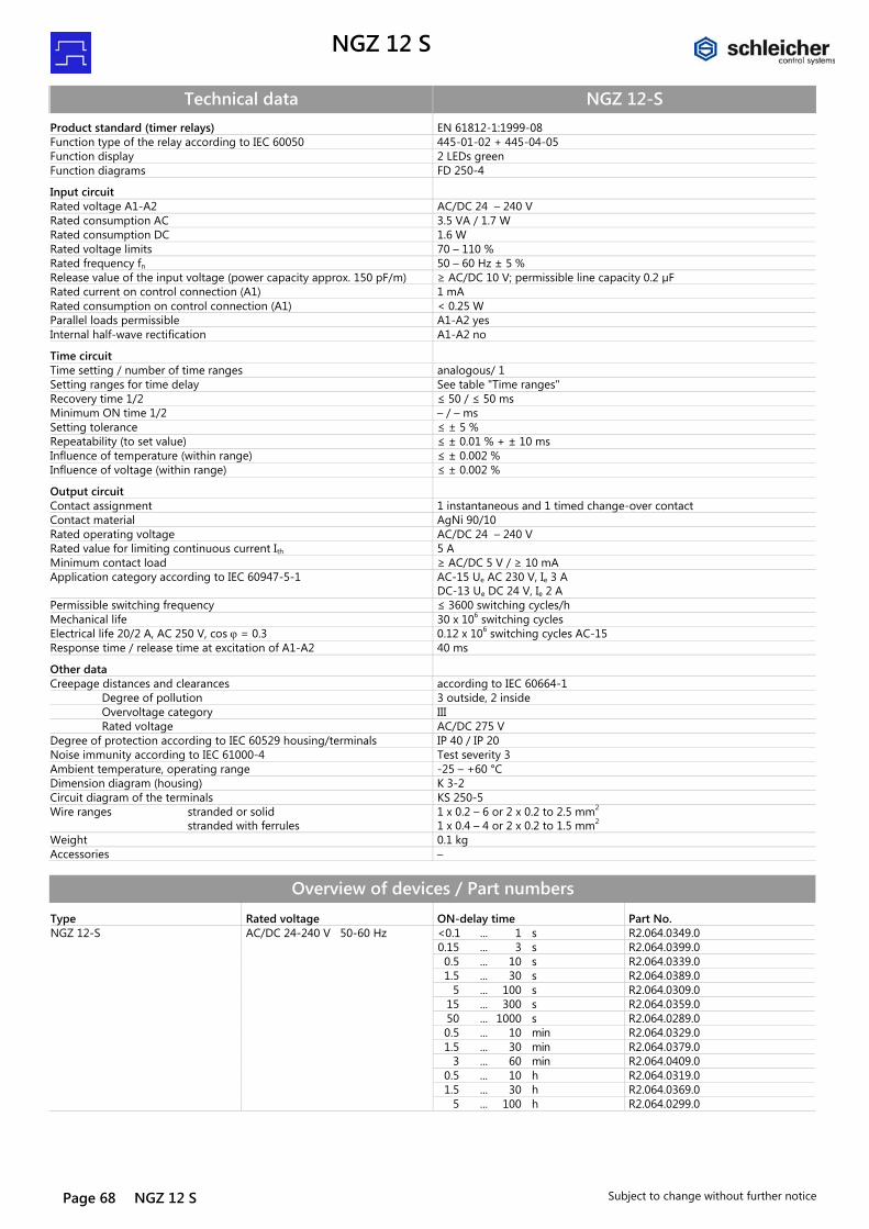
Technical data NGZ 12-S Product standard (timer relays) EN 61812-1:1999-08 Function type of the relay according to IEC 60050 445-01-02 + 445-04-05 Function display 2 LEDs green Function diagrams FD 250-4
Input circuit
Rated voltage A1-A2 AC/DC 24 – 240 V Rated consumption AC 3.5 VA / 1.7 W Rated consumption DC 1.6 W Rated voltage limits 70 – 110 % Rated frequency fn 50 – 60 Hz ± 5 % Release value of the input voltage (power capacity approx. 150 pF/m) ≥ AC/DC 10 V; permissible line capacity 0.2 µF Rated current on control connection (A1) 1 mA Rated consumption on control connection (A1) < 0.25 W Parallel loads permissible A1-A2 yes Internal half-wave rectification A1-A2 no
Time circuit
Time setting / number of time ranges analogous/ 1 Setting ranges for time delay See table "Time ranges" Recovery time 1/2 ≤ 50 / ≤ 50 ms Minimum ON time 1/2 – / – ms Setting tolerance ≤ ± 5 % Repeatability (to set value) ≤ ± 0.01 % + ± 10 ms Influence of temperature (within range) ≤ ± 0.002 % Influence of voltage (within range) ≤ ± 0.002 %
Output circuit
Contact assignment 1 instantaneous and 1 timed change-over contact Contact material AgNi 90/10 Rated operating voltage AC/DC 24 – 240 V Rated value for limiting continuous current Ith 5 A Minimum contact load ≥ AC/DC 5 V / ≥ 10 mA Application category according to IEC 60947-5-1 AC-15 Ue AC 230 V, Ie 3 A
DC-13 Ue DC 24 V, Ie 2 A Permissible switching frequency ≤ 3600 switching cycles/h Mechanical life 30 x 106 switching cycles Electrical life 20/2 A, AC 250 V, cos ϕ = 0.3 0.12 x 10⁶ switching cycles AC-15 Response time / release time at excitation of A1-A2 40 ms
Other data
Creepage distances and clearances according to IEC 60664-1 Degree of pollution 3 outside, 2 inside Overvoltage category III Rated voltage AC/DC 275 V Degree of protection according to IEC 60529 housing/terminals IP 40 / IP 20 Noise immunity according to IEC 61000-4 Test severity 3 Ambient temperature, operating range -25 – +60 °C Dimension diagram (housing) K 3-2 Circuit diagram of the terminals KS 250-5 Wire ranges stranded or solid stranded with ferrules
1 x 0.2 – 6 or 2 x 0.2 to 2.5 mm2 1 x 0.4 – 4 or 2 x 0.2 to 1.5 mm2
Weight 0.1 kg Accessories –
Overview of devices / Part numbers Type Rated voltage ON-delay time Part No. NGZ 12-S AC/DC 24-240 V 50-60 Hz <0.1 ... 1 s R2.064.0349.0 0.15 ... 3 s R2.064.0399.0 0.5 ... 10 s R2.064.0339.0 1.5 ... 30 s R2.064.0389.0 5 ... 100 s R2.064.0309.0 15 ... 300 s R2.064.0359.0 50 ... 1000 s R2.064.0289.0 0.5 ... 10 min R2.064.0329.0 1.5 ... 30 min R2.064.0379.0 3 ... 60 min R2.064.0409.0 0.5 ... 10 h R2.064.0319.0 1.5 ... 30 h R2.064.0369.0 5 ... 100 h R2.064.0299.0
NGZ 71
Subject to change without further notice NGZ 71 Page 69
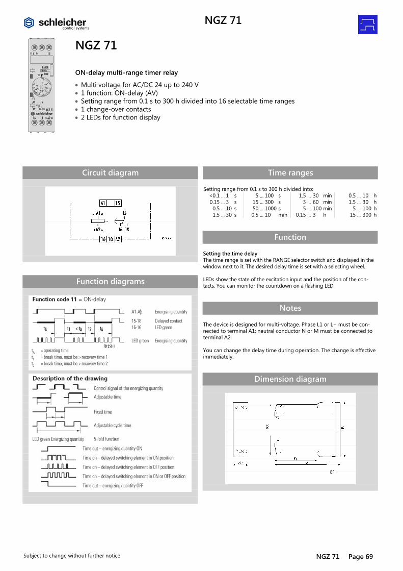
NGZ 71
ON-delay multi-range timer relay
• Multi voltage for AC/DC 24 up to 240 V • 1 function: ON-delay (AV) • Setting range from 0.1 s to 300 h divided into 16 selectable time ranges • 1 change-over contacts • 2 LEDs for function display
Circuit diagram
Function diagrams
Time ranges Setting range from 0.1 s to 300 h divided into: <0.1 ... 1 s 5 ... 100 s 1.5 ... 30 min 0.5 ... 10 h 0.15 ... 3 s 15 ... 300 s 3 ... 60 min 1.5 ... 30 h 0.5 ... 10 s 50 ... 1000 s 5 ... 100 min 5 ... 100 h 1.5 ... 30 s 0.5 ... 10 min 0.15 ... 3 h 15 ... 300 h
Function Setting the time delay The time range is set with the RANGE selector switch and displayed in the window next to it. The desired delay time is set with a selecting wheel. LEDs show the state of the excitation input and the position of the con-tacts. You can monitor the countdown on a flashing LED.
Notes The device is designed for multi-voltage. Phase L1 or L+ must be con-nected to terminal A1; neutral conductor N or M must be connected to terminal A2. You can change the delay time during operation. The change is effective immediately.
Dimension diagram

NGZ 71 DZ
Page 70 NGZ 71 Subject to change without further notice
Technical data NGZ 71 Product standard (timer relays) EN 61812-1:1999-08 Function type of the relay according to IEC 60050 445-01-02 Function display 2 LEDs green Function diagrams FD 250-1
Input circuit
Rated voltage A1-A2 AC/DC 24 – 240 V Rated consumption AC 3.5 VA / 1.7 W Rated consumption DC 1.6 W Rated voltage limits 70 – 110 % Rated frequency fn 50 – 60 Hz ± 5 % Release value of the input voltage (power capacity approx. 150 pF/m) ≥ AC/DC 10 V; permissible line capacity 0.2 µF Rated current on control connection (A1) 1 mA Rated consumption on control connection (A1) < 0.25 W Parallel loads permissible A1-A2 yes Internal half-wave rectification A1-A2 no
Time circuit
Time setting / number of time ranges analogous/ 16 Setting ranges for time delay See table "Time ranges" Recovery time 1/2 ≤ 50 / ≤ 50 ms Minimum ON time 1/2 – / – ms Setting tolerance ≤ ± 5 % Repeatability (to set value) ≤ ± 0.01 % + ± 10 ms Influence of temperature (within range) ≤ ± 0.002 % Influence of voltage (within range) ≤ ± 0.002 %
Output circuit
Contact assignment 1 change-over contacts Contact material AgNi 90/10 Rated operating voltage AC/DC 24 – 240 V Rated value for limiting continuous current Ith 5 A Minimum contact load ≥ AC/DC 5 V / ≥ 10 mA Application category according to IEC 60947-5-1 AC-15 Ue AC 230 V, Ie 3 A
DC-13 Ue DC 24 V, Ie 2 A Permissible switching frequency ≤ 3600 switching cycles/h Mechanical life 30 x 106 switching cycles Electrical life 20/2 A, AC 250 V, cos ϕ = 0.3 0.12 x 10⁶ switching cycles AC-15 Response time / release time at excitation of A1-A2 40 ms
Other data
Creepage distances and clearances according to IEC 60664-1 Degree of pollution 3 outside, 2 inside Overvoltage category III Rated voltage AC/DC 275 V Degree of protection according to IEC 60529 housing/terminals IP 40 / IP 20 Noise immunity according to IEC 61000-4 Test severity 3 Ambient temperature, operating range -25 – +60 °C Dimension diagram (housing) K 3-1 Circuit diagram of the terminals KS 250-1 Wire ranges stranded or solid stranded with ferrules
1 x 0.2 – 6 or 2 x 0.2 to 2.5 mm2 1 x 0.4 – 4 or 2 x 0.2 to 1.5 mm2
Weight 0.1 kg Accessories –
Overview of devices / Part numbers Type Rated voltage ON-delay time Part No. NGZ 71 AC/DC 24-240 V 50-60 Hz See table "Time ranges" R2.065.0069.0
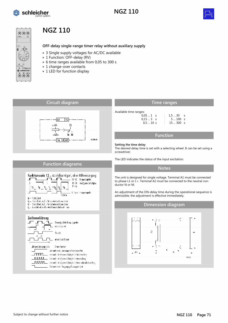
NGZ 110
Subject to change without further notice NGZ 110 Page 71
Timer and switching relays Zeitrelais Rückfallverzögerung Register:
NGZ 110
OFF-delay single-range timer relay without auxiliary supply
• 3 Single supply voltages for AC/DC available • 1 Function: OFF-delay (RV) • 6 time ranges available from 0,05 to 300 s • 1 change-over contacts • 1 LED for function display
Circuit diagram
Function diagrams
Time ranges Available time ranges: 0,05 ... 1 s 1,5 ... 30 s 0,15 ... 3 s 5 ... 100 s 0,5 ... 10 s 15 ... 300 s
Function Setting the time delay The desired delay time is set with a selecting wheel. It can be set using a screwdriver. The LED indicates the status of the input excitation.
Notes The unit is designed for single voltage. Terminal A1 must be connected to phase L1 or L+. Terminal A2 must be connected to the neutral con-ductor N or M. An adjustment of the ON-delay time during the operational sequence is admissible, the adjustment is effective immediately.
Dimension diagram
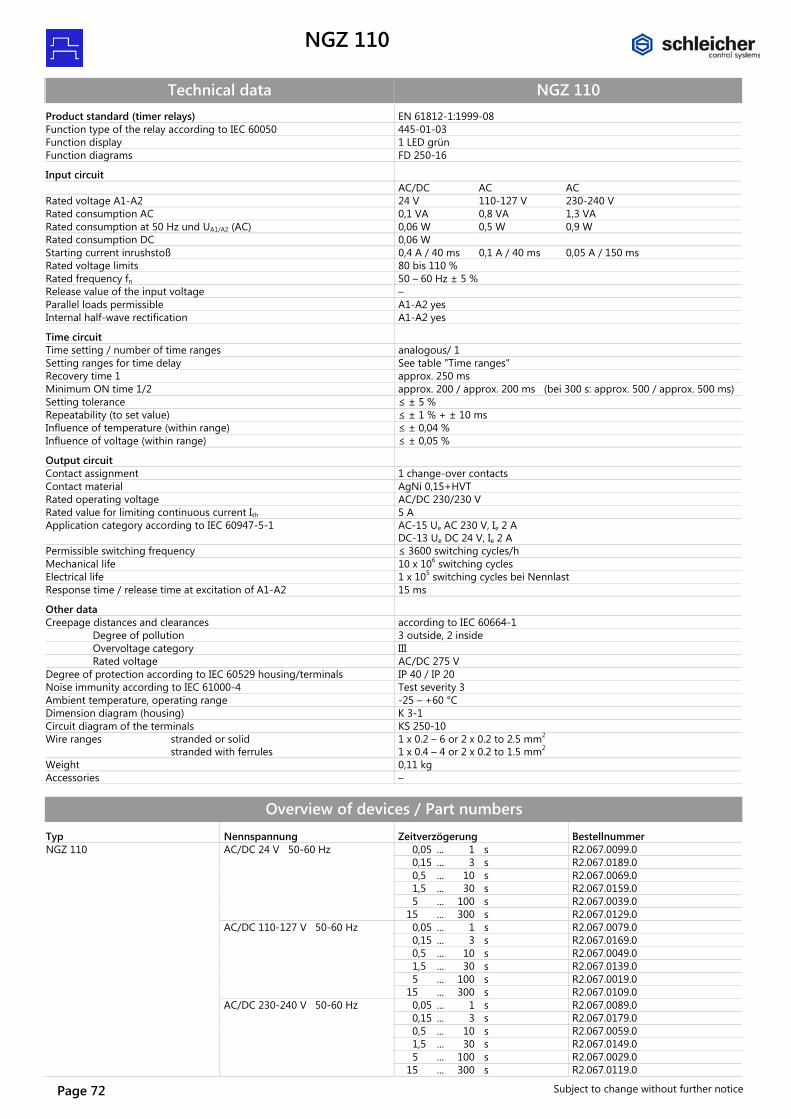
NGZ 110
Page 72 Subject to change without further notice
Technical data NGZ 110 Product standard (timer relays) EN 61812-1:1999-08 Function type of the relay according to IEC 60050 445-01-03 Function display 1 LED grün Function diagrams FD 250-16
Input circuit
AC/DC AC AC Rated voltage A1-A2 24 V 110-127 V 230-240 V Rated consumption AC 0,1 VA 0,8 VA 1,3 VA Rated consumption at 50 Hz und UA1/A2 (AC) 0,06 W 0,5 W 0,9 W Rated consumption DC 0,06 W Starting current inrushstoß 0,4 A / 40 ms 0,1 A / 40 ms 0,05 A / 150 ms Rated voltage limits 80 bis 110 % Rated frequency fn 50 – 60 Hz ± 5 % Release value of the input voltage – Parallel loads permissible A1-A2 yes Internal half-wave rectification A1-A2 yes
Time circuit
Time setting / number of time ranges analogous/ 1 Setting ranges for time delay See table "Time ranges" Recovery time 1 approx. 250 ms Minimum ON time 1/2 approx. 200 / approx. 200 ms (bei 300 s: approx. 500 / approx. 500 ms) Setting tolerance ≤ ± 5 % Repeatability (to set value) ≤ ± 1 % + ± 10 ms Influence of temperature (within range) ≤ ± 0,04 % Influence of voltage (within range) ≤ ± 0,05 %
Output circuit
Contact assignment 1 change-over contacts Contact material AgNi 0,15+HVT Rated operating voltage AC/DC 230/230 V Rated value for limiting continuous current Ith 5 A Application category according to IEC 60947-5-1 AC-15 Ue AC 230 V, Ie 2 A
DC-13 Ue DC 24 V, Ie 2 A Permissible switching frequency ≤ 3600 switching cycles/h Mechanical life 10 x 106 switching cycles Electrical life 1 x 10⁵ switching cycles bei Nennlast Response time / release time at excitation of A1-A2 15 ms
Other data
Creepage distances and clearances according to IEC 60664-1 Degree of pollution 3 outside, 2 inside Overvoltage category III Rated voltage AC/DC 275 V Degree of protection according to IEC 60529 housing/terminals IP 40 / IP 20 Noise immunity according to IEC 61000-4 Test severity 3 Ambient temperature, operating range -25 – +60 °C Dimension diagram (housing) K 3-1 Circuit diagram of the terminals KS 250-10 Wire ranges stranded or solid stranded with ferrules
1 x 0.2 – 6 or 2 x 0.2 to 2.5 mm2 1 x 0.4 – 4 or 2 x 0.2 to 1.5 mm2
Weight 0,11 kg Accessories –
Overview of devices / Part numbers Typ Nennspannung Zeitverzögerung Bestellnummer NGZ 110 AC/DC 24 V 50-60 Hz 0,05 ... 1 s R2.067.0099.0 0,15 ... 3 s R2.067.0189.0 0,5 ... 10 s R2.067.0069.0 1,5 ... 30 s R2.067.0159.0 5 ... 100 s R2.067.0039.0 15 ... 300 s R2.067.0129.0 AC/DC 110-127 V 50-60 Hz 0,05 ... 1 s R2.067.0079.0 0,15 ... 3 s R2.067.0169.0 0,5 ... 10 s R2.067.0049.0 1,5 ... 30 s R2.067.0139.0 5 ... 100 s R2.067.0019.0 15 ... 300 s R2.067.0109.0 AC/DC 230-240 V 50-60 Hz 0,05 ... 1 s R2.067.0089.0 0,15 ... 3 s R2.067.0179.0 0,5 ... 10 s R2.067.0059.0 1,5 ... 30 s R2.067.0149.0 5 ... 100 s R2.067.0029.0 15 ... 300 s R2.067.0119.0
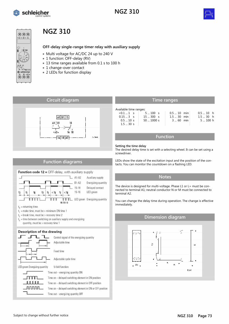
NGZ 310
Subject to change without further notice NGZ 310 Page 73
Timer and switching relays Zeitrelais Rückfallverzögerung Register:
NGZ 310
OFF-delay single-range timer relay with auxiliary supply
• Multi voltage for AC/DC 24 up to 240 V • 1 function: OFF-delay (RV) • 13 time ranges available from 0.1 s to 100 h • 1 change-over contact • 2 LEDs for function display
Circuit diagram
Function diagrams
Time ranges Available time ranges: <0.1 ... 1 s 5 ... 100 s 0.5 ... 10 min 0.5 ... 10 h 0.15 ... 3 s 15 ... 300 s 1.5 ... 30 min 1.5 ... 30 h 0.5 ... 10 s 50 ... 1000 s 3 ... 60 min 5 ... 100 h 1.5 ... 30 s
Function Setting the time delay The desired delay time is set with a selecting wheel. It can be set using a screwdriver. LEDs show the state of the excitation input and the position of the con-tacts. You can monitor the countdown on a flashing LED.
Notes The device is designed for multi-voltage. Phase L1 or L+ must be con-nected to terminal A1; neutral conductor N or M must be connected to terminal A2. You can change the delay time during operation. The change is effective immediately.
Dimension diagram

NGZ 310
Page 74 NGZ 310 Subject to change without further notice
Technical data NGZ 310 Product standard (timer relays) EN 61812-1:1999-08 Function type of the relay according to IEC 60050 445-01-04 + 445-03-02 Function display 2 LEDs green Function diagrams FD 250-10
Input circuit
Rated voltage A1-A2 AC/DC 24 – 240 V Rated consumption AC 3.5 VA / 1.7 W Rated consumption DC 1.6 W Rated voltage limits 70 – 110 % Rated frequency fn 50 – 60 Hz ± 5 % Release value of the input voltage (power capacity approx. 150 pF/m) ≥ AC/DC 10 V; permissible line capacity 0.2 µF Rated current on control connection (B1-A2) 1 mA Rated consumption on control connection (B1-A2) < 0.25 W Parallel loads permissible A1-A2 yes / B1-A1 yes Internal half-wave rectification A1-A2 no / B1-A1 yes
Time circuit
Time setting / number of time ranges analogous/ 1 Setting ranges for time delay See table "Time ranges" Recovery time 1/2 0 / 0 ms Minimum ON time 1/2 ≤ 25 / – ms Setting tolerance ≤ ± 5 % Repeatability (to set value) ≤ ± 0.01 % + ± 10 ms Influence of temperature (within range) ≤ ± 0.002 % Influence of voltage (within range) ≤ ± 0.002 %
Output circuit
Contact assignment 1 change-over contacts Contact material AgNi 90/10 Rated operating voltage AC/DC 24 – 240 V Rated value for limiting continuous current Ith 5 A Minimum contact load ≥ AC/DC 5 V / ≥ 10 mA Application category according to IEC 60947-5-1 AC-15 Ue AC 230 V, Ie 3 A DC-13 Ue DC 24 V, Ie 2 A Permissible switching frequency ≤ 3600 switching cycles/h Mechanical life 30 x 106 switching cycles Electrical life 20/2 A, AC 250 V, cos ϕ = 0.3 0.12 x 10⁶ switching cycles AC-15 Response time / release time at excitation of A1-A2 40 ms Response time / release time at excitation of B1-A2 20 ms
Other data
Creepage distances and clearances according to IEC 60664-1 Degree of pollution 3 outside, 2 inside Overvoltage category III Rated voltage AC/DC 275 V Degree of protection according to IEC 60529 housing/terminals IP 40 / IP 20 Noise immunity according to IEC 61000-4 Test severity 3 Ambient temperature, operating range -25 – +60 °C Dimension diagram (housing) K 3-1 Circuit diagram of the terminals KS 250-8 Wire ranges stranded or solid stranded with ferrules
1 x 0.2 – 6 or 2 x 0.2 to 2.5 mm2 1 x 0.4 – 4 or 2 x 0.2 to 1.5 mm2
Weight 0.1 kg Accessories –
Overview of devices / Part numbers Type Rated voltage ON-delay time Part No. NGZ 310 AC/DC 24-240 V 50-60 Hz <0.1 ... 1 s R2.067.0329.0 0.15 ... 3 s R2.067.0379.0 0.5 ... 10 s R2.067.0319.0 1.5 ... 30 s R2.067.0369.0 5 ... 100 s R2.067.0289.0 15 ... 300 s R2.067.0339.0 50 ... 1000 s R2.067.0269.0 0.5 ... 10 min R2.067.0309.0 1.5 ... 30 min R2.067.0359.0 3 ... 60 min R2.067.0389.0 0.5 ... 10 h R2.067.0299.0 1.5 ... 30 h R2.067.0349.0 5 ... 100 h R2.067.0279.0
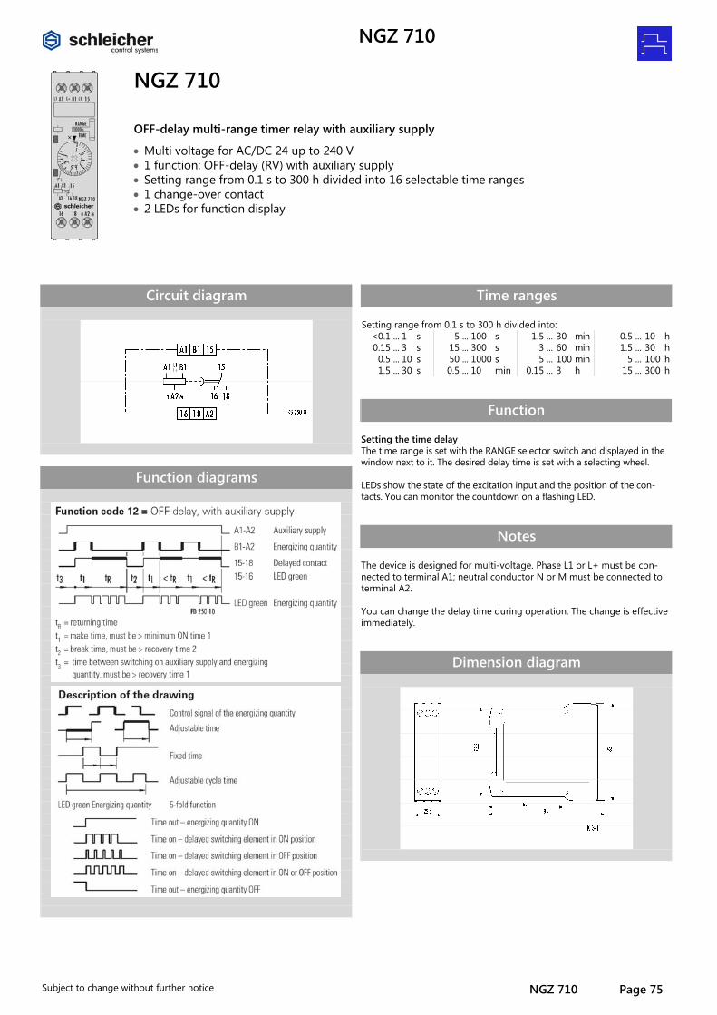
NGZ 710
Subject to change without further notice NGZ 710 Page 75
NGZ 710
OFF-delay multi-range timer relay with auxiliary supply
• Multi voltage for AC/DC 24 up to 240 V • 1 function: OFF-delay (RV) with auxiliary supply • Setting range from 0.1 s to 300 h divided into 16 selectable time ranges • 1 change-over contact • 2 LEDs for function display
Circuit diagram
Function diagrams
Time ranges Setting range from 0.1 s to 300 h divided into: <0.1 ... 1 s 5 ... 100 s 1.5 ... 30 min 0.5 ... 10 h 0.15 ... 3 s 15 ... 300 s 3 ... 60 min 1.5 ... 30 h 0.5 ... 10 s 50 ... 1000 s 5 ... 100 min 5 ... 100 h 1.5 ... 30 s 0.5 ... 10 min 0.15 ... 3 h 15 ... 300 h
Function Setting the time delay The time range is set with the RANGE selector switch and displayed in the window next to it. The desired delay time is set with a selecting wheel. LEDs show the state of the excitation input and the position of the con-tacts. You can monitor the countdown on a flashing LED.
Notes The device is designed for multi-voltage. Phase L1 or L+ must be con-nected to terminal A1; neutral conductor N or M must be connected to terminal A2. You can change the delay time during operation. The change is effective immediately.
Dimension diagram

NGZ 710
Page 76 NGZ 710 Subject to change without further notice
Technical data NGZ 710 Product standard (timer relays) EN 61812-1:1999-08 Function type of the relay according to IEC 60050 445-01-04 + 445-03-02 Function display 2 LEDs green Function diagrams FD 250-10
Input circuit
Rated voltage A1-A2 AC/DC 24 – 240 V Rated consumption AC 3.5 VA / 1.7 W Rated consumption DC 1.6 W Rated voltage limits 70 – 110 % Rated frequency fn 50 – 60 Hz ± 5 % Release value of the input voltage (power capacity approx. 150 pF/m) ≥ AC/DC 10 V; permissible line capacity 0.2 µF Rated current on control connection (B1-A2) 1 mA Rated consumption on control connection (B1-A2) < 0.25 W Parallel loads permissible A1-A2 yes / B1-A2 yes Internal half-wave rectification A1-A2 no / B1-A2 yes
Time circuit
Time setting / number of time ranges analogous/ 16 Setting ranges for time delay See table "Time ranges" Recovery time 1/2/3 0 / 0 / – ms Minimum ON time 1/2 ≤ 25 / – ms Setting tolerance ≤ ± 5 % Repeatability (to set value) ≤ ± 0.01 % + ± 10 ms Influence of temperature (within range) ≤ ± 0.002 % Influence of voltage (within range) ≤ ± 0.002 %
Output circuit
Contact assignment 1 change-over contacts Contact material AgNi 90/10 Rated operating voltage AC/DC 24 – 240 V Rated value for limiting continuous current Ith 5 A Minimum contact load ≥ AC/DC 5 V / ≥ 10 mA Application category according to IEC 60947-5-1 AC-15 Ue AC 230 V, Ie 3 A
DC-13 Ue DC 24 V, Ie 2 A Permissible switching frequency ≤ 3600 switching cycles/h Mechanical life 30 x 106 switching cycles Electrical life 20/2 A, AC 250 V, cos ϕ = 0.3 0.12 x 10⁶ switching cycles AC-15 Response time / release time at excitation of A1-A2 40 ms Response time / release time at excitation of B1-A2 20 ms
Other data
Creepage distances and clearances according to IEC 60664-1 Degree of pollution 3 outside, 2 inside Overvoltage category III Rated voltage AC/DC 275 V Degree of protection according to IEC 60529 housing/terminals IP 40 / IP 20 Noise immunity according to IEC 61000-4 Test severity 3 Ambient temperature, operating range -25 – +60 °C Dimension diagram (housing) K 3-1 Circuit diagram of the terminals KS 250-8 Wire ranges stranded or solid stranded with ferrules
1 x 0.2 – 6 or 2 x 0.2 to 2.5 mm2 1 x 0.4 – 4 or 2 x 0.2 to 1.5 mm2
Weight 0.1 kg Accessories –
Overview of devices / Part numbers Type Rated voltage ON-delay time Part No. NGZ 710 AC/DC 24-240 V 50-60 Hz See table "Time ranges" R2.065.0079.0

NGZ 720
Subject to change without further notice NGZ 720 Page 77
Timer and switching relays Zeitrelais Rückfallverzögerung Register:
NGZ 720
OFF-delay multi-range timer relay with auxiliary supply
• Multi voltage for AC/DC 24 up to 240 V • 1 function: OFF-delay (RV) with auxiliary supply • Setting range from 0.1 s to 300 h divided into 16 selectable time ranges • 2 change-over contact • 2 LEDs for function display
Circuit diagram
Function diagrams
Time ranges Setting range from 0.1 s to 300 h divided into: <0.1 ... 1 s 5 ... 100 s 1.5 ... 30 min 0.5 ... 10 h 0.15 ... 3 s 15 ... 300 s 3 ... 60 min 1.5 ... 30 h 0.5 ... 10 s 50 ... 1000 s 5 ... 100 min 5 ... 100 h 1.5 ... 30 s 0.5 ... 10 min 0.15 ... 3 h 15 ... 300 h
Function Setting the time delay The time range is set with the RANGE selector switch and displayed in the window next to it. The desired delay time is set with a selecting wheel. LEDs show the state of the excitation input and the position of the con-tacts. You can monitor the countdown on a flashing LED.
Notes The device is designed for multi-voltage. Phase L1 or L+ must be con-nected to terminal A1; neutral conductor N or M must be connected to terminal A2. You can change the delay time during operation. The change is effective immediately.
Dimension diagram

NGZ 720
Page 78 NGZ 720 Subject to change without further notice
Technical data NGZ 720 Product standard (timer relays) EN 61812-1:1999-08 Function type of the relay according to IEC 60050 445-01-04 + 445-03-02 Function display 2 LEDs green Function diagrams FD 250-11
Input circuit
Rated voltage A1-A2 AC/DC 24 – 240 V Rated consumption AC 3.5 VA / 1.7 W Rated consumption DC 1.6 W Rated voltage limits 70 – 110 % Rated frequency fn 50 – 60 Hz ± 5 % Release value of the input voltage (power capacity approx. 150 pF/m) ≥ AC/DC 10 V; permissible line capacity 0.2 µF Rated current on control connection (B1-A2) 1 mA Rated consumption on control connection (B1-A2) < 0.25 W Parallel loads permissible A1-A2 yes / B1-A2 yes Internal half-wave rectification A1-A2 no / B1-A2 yes
Time circuit
Time setting / number of time ranges analogous/ 16 Setting ranges for time delay See table "Time ranges" Recovery time 1/2/3 0 / 0 / – ms Minimum ON time 1/2 ≤ 25 / – ms Setting tolerance ≤ ± 5 % Repeatability (to set value) ≤ ± 0.01 % + ± 10 ms Influence of temperature (within range) ≤ ± 0.002 % Influence of voltage (within range) ≤ ± 0.002 %
Output circuit
Contact assignment 2 change-over contacts Contact material AgNi 90/10 Rated operating voltage AC/DC 24 – 240 V Rated value for limiting continuous current Ith 5 A Minimum contact load ≥ AC/DC 5 V / ≥ 10 mA Application category according to IEC 60947-5-1 AC-15 Ue AC 230 V, Ie 3 A
DC-13 Ue DC 24 V, Ie 2 A Permissible switching frequency ≤ 3600 switching cycles/h Mechanical life 30 x 106 switching cycles Electrical life 20/2 A, AC 250 V, cos ϕ = 0.3 0.12 x 10⁶ switching cycles AC-15 Response time / release time at excitation of A1-A2 40 ms Response time / release time at excitation of B1-A2 20 ms
Other data
Creepage distances and clearances according to IEC 60664-1 Degree of pollution 3 outside, 2 inside Overvoltage category III Rated voltage AC/DC 275 V Degree of protection according to IEC 60529 housing/terminals IP 40 / IP 20 Noise immunity according to IEC 61000-4 Test severity 3 Ambient temperature, operating range -25 – +60 °C Dimension diagram (housing) K 3-3 Circuit diagram of the terminals KS 250-9 Wire ranges stranded or solid stranded with ferrules
1 x 0.2 – 6 or 2 x 0.2 to 2.5 mm2 1 x 0.4 – 4 or 2 x 0.2 to 1.5 mm2
Weight 0.13 kg Accessories –
Overview of devices / Part numbers Type Rated voltage ON-delay time Part No. NGZ 720 AC/DC 24-240 V 50-60 Hz See table "Time ranges" R2.065.0099.0

NGZP 32
Subject to change without further notice NGZP 32 Page 79
NGZP 32
ON-delay single-range timer relay with remote potentiometer connection
• Multi voltage for AC/DC 24 to 240 V • 1 function: ON-delay (AV) • 13 time ranges available from 0.1 s to 100 h • Remote potentiometer connection • 2 change-over contact • 2 LEDs for function display
Circuit diagram
Function diagrams
Accessories Accessories: Remote potentiometer FP 10 k
Time ranges Available time ranges: <0.1 ... 1 s 5 ... 100 s 0.5 ... 10 min 0.5 ... 10 h 0.15 ... 3 s 15 ... 300 s 1.5 ... 30 min 1.5 ... 30 h 0.5 ... 10 s 50 ... 1000 s 3 ... 60 min 5 ... 100 h 1.5 ... 30 s
Function Setting the time delay The desired delay time is set with a selecting wheel. It can be set using a screwdriver. Connecting a remote potentiometer allows you to set parameters at greater distances. When a remote potentiometer is used, the time select-ing wheel is to be set to the right-hand stop above the largest value. Operation without remote potentiometer does not require a jumper on the device. LEDs show the state of the excitation input and the position of the con-tacts. You can monitor the countdown on a flashing LED.
Notes The device is designed for multi-voltage. Phase L1 or L+ must be con-nected to terminal A1; neutral conductor N or M must be connected to terminal A2. You can change the delay time during operation. The change is effective immediately.
Dimension diagram

NGZP 32
Page 80 NGZP 32 Subject to change without further notice
Technical data NGZP 32 Product standard (timer relays) EN 61812-1:1999-08 Function type of the relay according to IEC 60050 445-01-02 Function display 2 LEDs green Function diagrams FD 250-2
Input circuit
Rated voltage A1-A2 AC/DC 24 – 240 V Rated consumption AC 3.5 VA / 1.7 W Rated consumption DC 1.6 W Rated voltage limits 70 – 110 % Rated frequency fn 50 – 60 Hz ± 5 % Release value of the input voltage (power capacity approx. 150 pF/m) ≥ AC/DC 10 V; permissible line capacity 0.2 µF Rated current on control connection (A1) 1 mA Rated consumption on control connection (A1) < 0.25 W Parallel loads permissible A1-A2 yes Internal half-wave rectification A1-A2 no
Time circuit
Time setting / number of time ranges analog (intern + extern) / 1 Setting ranges for time delay See table "Time ranges" Recovery time 1/2 ≤ 50 / ≤ 50 ms Minimum ON time 1/2 – / – Setting tolerance ≤ ± 5 % Repeatability (to set value) ≤ ± 0.01 % + ± 10 ms Influence of temperature (within range) ≤ ± 0.002 % Influence of voltage (within range) ≤ ± 0.002 %
Output circuit
Contact assignment 2 change-over contacts Contact material AgNi 90/10 Rated operating voltage AC/DC 24 – 240 V Rated value for limiting continuous current Ith 5 A Minimum contact load ≥ AC/DC 5 V / ≥ 10 mA Application category according to IEC 60947-5-1 AC-15 Ue AC 230 V, Ie 3 A
DC-13 Ue DC 24 V, Ie 2 A Permissible switching frequency ≤ 3600 switching cycles/h Mechanical life 30 x 106 switching cycles Electrical life 20/2 A, AC 250 V, cos ϕ = 0.3 0.12 x 10⁶ switching cycles AC-15 Response time / release time at excitation of A1-A2 40 ms
Other data
Creepage distances and clearances according to IEC 60664-1 Degree of pollution 3 outside, 2 inside Overvoltage category III Rated voltage AC/DC 275 V Degree of protection according to IEC 60529 housing/terminals IP 40 / IP 20 Noise immunity according to IEC 61000-4 Test severity 3 Ambient temperature, operating range -25 – +60 °C Dimension diagram (housing) K 3-3 Circuit diagram of the terminals KS 250-4 Wire ranges stranded or solid stranded with ferrules
1 x 0.2 – 6 or 2 x 0.2 to 2.5 mm2 1 x 0.4 – 4 or 2 x 0.2 to 1.5 mm2
Weight 0.14 kg Accessories Remote potentiometer FP 10 k
Overview of devices / Part numbers Type Rated voltage ON-delay time Part No. NGZP 32 AC/DC 24-240 V 50-60 Hz <0.1 ... 1 s R2.064.0619.0 0.15 ... 3 s R2.064.0669.0 0.5 ... 10 s R2.064.0609.0 1.5 ... 30 s R2.064.0659.0 5 ... 100 s R2.064.0579.0 15 ... 300 s R2.064.0629.0 50 ... 1000 s R2.064.0559.0 0.5 ... 10 min R2.064.0599.0 1.5 ... 30 min R2.064.0649.0 3 ... 60 min R2.064.0679.0 0.5 ... 10 h R2.064.0589.0 1.5 ... 30 h R2.064.0639.0 5 ... 100 h R2.064.0569.0

SSP 56
Subject to change without further notice SSP 56 Page 81
SSP 56 SSP 33
SSP 72 SSP 34
Flip-flop relay
• Devices for Mono voltage • Function: flip-flop relay • contact assembly:
SSP 56 = 3 NO and 3 NC contacts SSP 72 = 2 changers SSP 33 = 3 changers SSP 34 = 4 changers
SSP 56, SSP 72 SSP 33, SSP 34
Wiring diagram
Function The flip-flop relay consists of two separate magnet systems which mutually mechanically latch shut. Upon impulse or constant excitation of the mag-net system equipped with contacts, the contacts toggle to the operating position. At the same time, the catches on the relay anchors latch shut, so that even in the event of a voltage failure and/or a voltage interrup-tion, the operating position of the contacts is maintained. Upon excitation of the non-equipped magnet system, the latch is released and the con-tacts return to the default position. On the device types SSP 56 and SSP 72, a lever protruding from the front plate prompts a manual shift in the magnet system and indicates the position of the magnet and/or the contact. On the device types SSP 33 and SSP 34, two pushbuttons are available for this purpose. The relay contacts have no preferred position. If both inductors are excited simultaneously, the operating position of the contacts is maintained.
Function diagram
Dimensional drawings

SSP 56
Page 82 SSP 56 Subject to change without further notice
Technical Data SSP 56 SSP 72 SSP 33 SSP 34 Function type according to DIN VDE 0435 Section 110:04.89 Electro-mechanical flip-flop relay for Mono voltage
Item 2.4: bi-stable relay Function indicator Positioning lever Positioning lever Pushbuttons Pushbuttons Function diagram FD 0022a
Supply circuit
Nominal voltage UN see Device overview Rated output Re 1 at 50 Hz and UN (AC) Power-on approx. 13 VA /
approx. 4.5 W approx. 13 VA / approx. 4.5 W
approx. 18 VA / approx. 6.5 W
approx. 18 VA / approx. 6.5 W
Rated output Re 1 at 50 Hz and UN (AC) Hold approx. 4 VA / approx. 1.5 W
approx. 4 VA / approx. 1.5 W
approx. 5.2 VA / approx. 1.8 W
approx. 5.2 VA / approx. 1.8 W
Rated output Re 2 at 50 Hz and UN (AC) Power-on approx. 10.5 VA / approx. 3.5 W Rated output Re 2 at 50 Hz and UN (AC) Hold approx. 3 VA / approx. 1 W Nominal frequency see Device overview Operating voltage range 0.8 to 1.1 x UN
Timing circuit
Time setting/Numbers of time domains –/– Available time domains – Standby reactivation interval – Minimum power-on time – Fallback value ≥ 15 % UN Parallel consumer loads permissible yes Internal one-way rectification direction no
Output circuit
contact assembly 3 NO contacts and 3 NC contacts
2 changers 3 changers 4 changers
Contact material Ag Cu Switching nominal voltage Un AC/DC 400 V max. steady current In 5 A Usage category according to EN 60947-5-1:1991 AC-15: Ue 230 V AC, Ie 2 A DC-13: Ue 24 V DC, Ie 2 A Permissible frequency of operation ≤ 3600 switching cycles/h Mechanical service life 10 x 106 switching cycles Response time ≤ 20 ms Fallback time ≤ 25 ms
General Data
Air and crawl sections between the electric circuits according to DIN VDE 0110-1:04.97 Rated surge voltage 5 kV Over-voltage category III Degree of contamination 3 exterior, 2 interior Rated voltage 400 V AC Testing voltage Ueff 50 Hz according to DIN VDE 0110-1, Table A.1
2.7 kV
Safety class for casing/terminals according to DIN VDE 0470 Section 1:11.92
IP 30/IP 20
Interference emission EN 50081-1:03.93. -2:03.94 Interference resistance EN 50082-2:1995 Ambient temperature, work area –10 to +55 °C Dimensional drawing S 3-5 S 3-5 S 2-1 S 2-1 Wiring diagram KS 5161/2 KS 5172/2 KS 5143/2 KS 5137/2 Weight 0.5 kg 0.5 kg 0.6 kg 0.6 kg Accessories –
Device overview / Order numbers Type Rated voltage Order number SSP 56 AC 24 V 50 Hz R2.153.0149.0 AC 42 V 50 Hz R2.153.0089.0 AC 48 V 50 Hz R2.153.0049.0 AC 110 V 50 Hz R2.153.0059.0 AC 110 V 60 Hz R2.153.0079.0 AC 120-131 V 60 Hz R2.153.0139.0 AC 230 V 50 Hz R2.153.0109.0 SSP 72 AC 24 V 50 Hz R2.153.0099.0 AC 110-115 V 60 Hz R2.153.0109.0 AC 230 V 50 Hz R2.153.0029.0 SSP 33 AC 24 V 50 Hz R2.152.0099.0 AC 230 V 50 Hz R2.152.0179.0 SSP 34 AC 110 V 50 Hz R2.152.0119.0 AC 230 V 50 Hz R2.152.0079.0
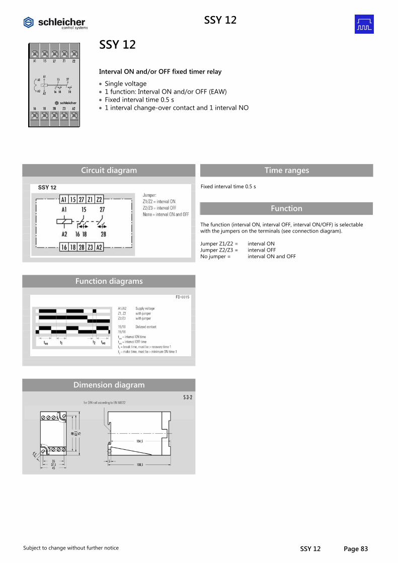
SSY 12
Subject to change without further notice SSY 12 Page 83
SSY 12
Interval ON and/or OFF fixed timer relay
• Single voltage • 1 function: Interval ON and/or OFF (EAW) • Fixed interval time 0.5 s • 1 interval change-over contact and 1 interval NO
Circuit diagram
Function diagrams
Dimension diagram
Time ranges Fixed interval time 0.5 s
Function The function (interval ON, interval OFF, interval ON/OFF) is selectable with the jumpers on the terminals (see connection diagram). Jumper Z1/Z2 = interval ON Jumper Z2/Z3 = interval OFF No jumper = interval ON and OFF
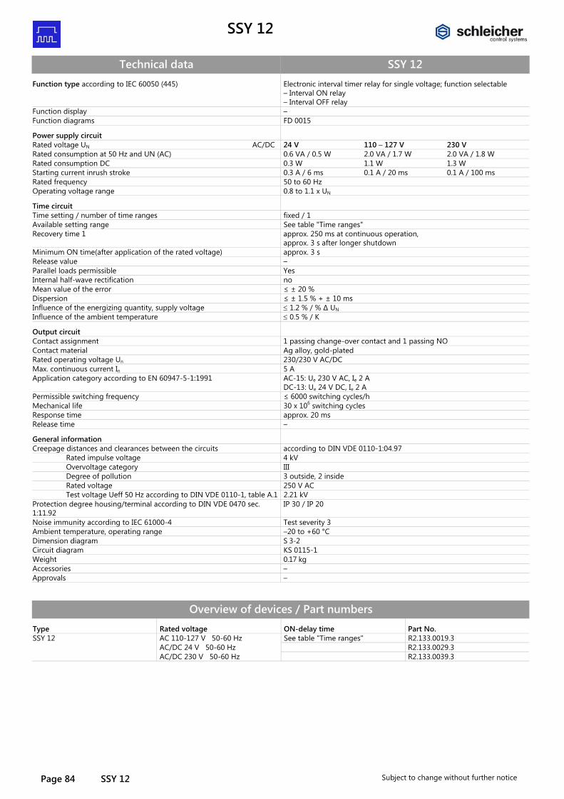
SSY 12
Page 84 SSY 12 Subject to change without further notice
Technical data SSY 12 Function type according to IEC 60050 (445) Electronic interval timer relay for single voltage; function selectable
– Interval ON relay – Interval OFF relay
Function display – Function diagrams FD 0015
Power supply circuit
Rated voltage UN AC/DC 24 V 110 – 127 V 230 V Rated consumption at 50 Hz and UN (AC) 0.6 VA / 0.5 W 2.0 VA / 1.7 W 2.0 VA / 1.8 W Rated consumption DC 0.3 W 1.1 W 1.3 W Starting current inrush stroke 0.3 A / 6 ms 0.1 A / 20 ms 0.1 A / 100 ms Rated frequency 50 to 60 Hz Operating voltage range 0.8 to 1.1 x UN
Time circuit
Time setting / number of time ranges fixed / 1 Available setting range See table "Time ranges" Recovery time 1 approx. 250 ms at continuous operation,
approx. 3 s after longer shutdown Minimum ON time(after application of the rated voltage) approx. 3 s Release value – Parallel loads permissible Yes Internal half-wave rectification no Mean value of the error ≤ ± 20 % Dispersion ≤ ± 1.5 % + ± 10 ms Influence of the energizing quantity, supply voltage ≤ 1.2 % / % ∆ UN Influence of the ambient temperature ≤ 0.5 % / K
Output circuit
Contact assignment 1 passing change-over contact and 1 passing NO Contact material Ag alloy, gold-plated Rated operating voltage Un 230/230 V AC/DC Max. continuous current In 5 A Application category according to EN 60947-5-1:1991 AC-15: Ue 230 V AC, Ie 2 A
DC-13: Ue 24 V DC, Ie 2 A Permissible switching frequency ≤ 6000 switching cycles/h Mechanical life 30 x 106 switching cycles Response time approx. 20 ms Release time –
General information
Creepage distances and clearances between the circuits according to DIN VDE 0110-1:04.97 Rated impulse voltage 4 kV Overvoltage category III Degree of pollution 3 outside, 2 inside Rated voltage 250 V AC Test voltage Ueff 50 Hz according to DIN VDE 0110-1, table A.1 2.21 kV Protection degree housing/terminal according to DIN VDE 0470 sec. 1:11.92
IP 30 / IP 20
Noise immunity according to IEC 61000-4 Test severity 3 Ambient temperature, operating range –20 to +60 °C Dimension diagram S 3-2 Circuit diagram KS 0115-1 Weight 0.17 kg Accessories – Approvals –
Overview of devices / Part numbers Type Rated voltage ON-delay time Part No. SSY 12 AC 110-127 V 50-60 Hz See table "Time ranges" R2.133.0019.3 AC/DC 24 V 50-60 Hz R2.133.0029.3 AC/DC 230 V 50-60 Hz R2.133.0039.3
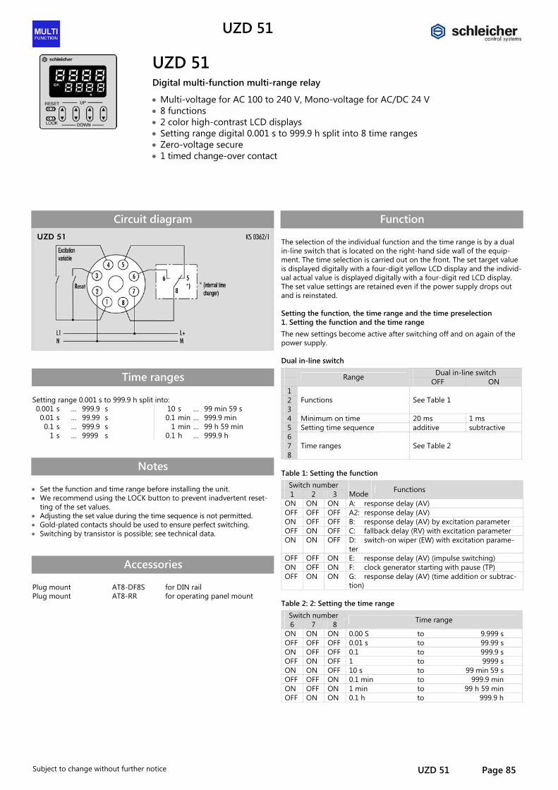
UZD 51
Subject to change without further notice UZD 51 Page 85
UZD 51
Digital multi-function multi-range relay
• Multi-voltage for AC 100 to 240 V, Mono-voltage for AC/DC 24 V • 8 functions • 2 color high-contrast LCD displays • Setting range digital 0.001 s to 999.9 h split into 8 time ranges • Zero-voltage secure • 1 timed change-over contact
Circuit diagram
Time ranges Setting range 0.001 s to 999.9 h split into: 0.001 s … 999.9 s 10 s … 99 min 59 s 0.01 s … 99.99 s 0.1 min … 999.9 min 0.1 s … 999.9 s 1 min … 99 h 59 min
1 s … 9999 s 0.1 h … 999.9 h
Notes • Set the function and time range before installing the unit. • We recommend using the LOCK button to prevent inadvertent reset-
ting of the set values. • Adjusting the set value during the time sequence is not permitted. • Gold-plated contacts should be used to ensure perfect switching. • Switching by transistor is possible; see technical data.
Accessories Plug mount Plug mount
AT8-DF8S AT8-RR
for DIN rail for operating panel mount
Function The selection of the individual function and the time range is by a dual in-line switch that is located on the right-hand side wall of the equip-ment. The time selection is carried out on the front. The set target value is displayed digitally with a four-digit yellow LCD display and the individ-ual actual value is displayed digitally with a four-digit red LCD display. The set value settings are retained even if the power supply drops out and is reinstated. Setting the function, the time range and the time preselection 1. Setting the function and the time range The new settings become active after switching off and on again of the power supply. Dual in-line switch
Dual in-line switch Range OFF ON 1 2 3
Functions See Table 1
4 Minimum on time 20 ms 1 ms 5 Setting time sequence additive subtractive 6 7 8
Time ranges See Table 2
Table 1: Setting the function
Switch number 1 2 3
Mode Functions
ON ON ON A: response delay (AV) OFF OFF OFF A2: response delay (AV) ON OFF OFF B: response delay (AV) by excitation parameter OFF ON OFF C: fallback delay (RV) with excitation parameter ON ON OFF D: switch-on wiper (EW) with excitation parame-
ter OFF OFF ON E: response delay (AV) (impulse switching) ON OFF ON F: clock generator starting with pause (TP) OFF ON ON G: response delay (AV) (time addition or subtrac-
tion) Table 2: 2: Setting the time range
Switch number 6 7 8 Time range
ON ON ON 0.00 S to 9.999 s OFF OFF OFF 0.01 s to 99.99 s ON OFF OFF 0.1 to 999.9 s OFF ON OFF 1 to 9999 s ON ON OFF 10 s to 99 min 59 s OFF OFF ON 0.1 min to 999.9 min ON OFF ON 1 min to 99 h 59 min OFF ON ON 0.1 h to 999.9 h
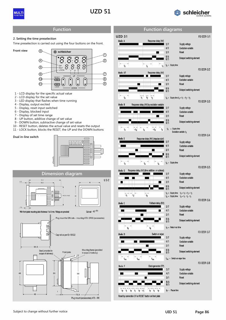
UZD 51
Subject to change without further notice UID 51 Page 86
Function 2. Setting the time preselection Time preselection is carried out using the four buttons on the front. Front view
1 - LCD display for the specific actual value 2 - LCD display for the set value 3 - LED display that flashes when time running 4 - Display, output excited 5 - Display, reset input switched 6 - Display, blocked input 7 - Display of set time range 8 - UP button, additive change of set value 9 - DOWN button, subtractive change of set value 10 - RESET button, deletes the actual value and resets the output 11 - LOCK button, blocks the RESET, the UP and the DOWN buttons Dual in-line switch
Dimension diagram
Function diagrams
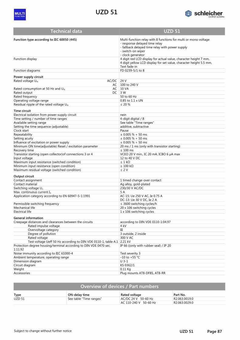
UZD 51
Subject to change without further notice UZD 51 Page 87
Technical data UZD 51 Function type according to IEC 60050 (445) Multi-function relay with 8 functions for multi or mono voltage
- response delayed time relay - fallback delayed time relay with power supply - switch-on wiper - clock generator
Function display 4 digit red LCD display for actual value, character height 7 mm, 4 digit yellow LCD display for set value, character height 5.5 mm, Text fade-in
Function diagrams FD 0239-5/1 to 8
Power supply circuit
Rated voltage UN AC/DC 24 V AC 100 to 240 V Rated consumption at 50 Hz and UN AC 10 VA Rated output DC 3 W Rated frequency 50 to 60 Hz Operating voltage range 0.85 to 1.1 x UN Residual ripple of the rated voltage UN ≤ 20 %
Time circuit
Electrical isolation from power supply circuit nein Time setting / number of time ranges 4-digit digital / 8 Available setting range See table "Time ranges" Setting the time sequence (adjustable) additive, subtractive Clock start Pause Repeatability ± 0.005 % + 50 ms Setting acuity ± 0.005 % + 50 ms Influence of excitation or power supply ± 0.005 % + 50 ms Minimum ON time(adjustable) Reset / excitation parameter 20 ms / 1 ms (only with transistor starting) Recovery time ≤ 100 ms Transistor starting (open collector)of connections 3 or 4 VCEO 20 V min., IC 20 mA, ICBO 6 µA max Input voltage 12 to 40 V DC Maximum input resistance (switched condition) ≤ 1 kΩ Minimum input resistance (open condition) ≥ 100 kΩ Maximum residual voltage (switched condition) ≤ 2 V
Output circuit
Contact assignment 1 timed change-over contact Contact material Ag alloy, gold-plated Switching voltage Un 230/30 V AC/DC Max. continuous current In 5 A Application category according to EN 60947-5-1:1991 AC-15: Ue 250 V AC, Ie 0.75 A
DC-13: Ue 30 V DC, Ie 2 A Permissible switching frequency ≤ 3600 switching cycles/h Mechanical life 20 x 106 switching cycles Electrical life 1 x 10⁶ switching cycles
General information
Creepage distances and clearances between the circuits according to DIN VDE 0110-1:04.97 Rated impulse voltage 4 kV Overvoltage category III Degree of pollution 3 outside, 2 inside Rated voltage 300 V AC Test voltage Ueff 50 Hz according to DIN VDE 0110-1, table A.1 2.21 kV Protection degree housing/terminal according to DIN VDE 0470 sec. 1:11.92
IP 66 ((only with rubber seal) / IP 20
Noise immunity according to IEC 61000-4 Test severity 3 Ambient temperature, operating range –10 to +55 °C Dimension diagram U 3-1 Circuit diagram KS 0362/1 Weight 0.11 Kg Accessories Plug mounts AT8-DF8S, AT8-RR
Overview of devices / Part numbers Type ON-delay time Rated voltage Part No. UZD 51 See table "Time ranges" AC/DC 24 V 50-60 Hz R2.063.0019.0 AC 110-240 V 50-60 Hz R2.063.0029.0
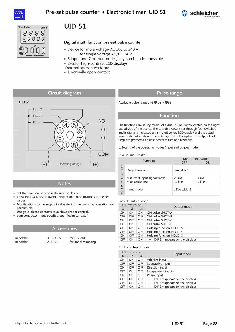
Pre-set pulse counter Electronic timer UID 51
Subject to change without further notice UID 51 Page 88
UID 51
Digital multi function pre-set pulse counter
• Device for multi voltage AC 100 to 240 V for single voltage AC/DC 24 V
• 5 input and 7 output modes; any combination possible • 2-color high-contrast LCD displays Protected against power failure
• 1 normally open contact
Circuit diagram
Notes • Set the function prior to installing the device. • Press the LOCK key to avoid unintentional modifications to the set
values. • Modifications to the setpoint value during the counting operation are
permissible. • Use gold-plated contacts to achieve proper control. • Semiconductor input possible; see “Technical data”
Accessories Pin holder Pin holder
AT8-DF8S AT8-RR
for DIN-rail for panel mounting
Pulse range Available pulse ranges: –999 bis +9999
Function The functions are set by means of a dual in-line switch located on the right lateral side of the device. The setpoint value is set through four switches and is digitally indicated on a 4-digit yellow LCD display and the actual value is digitally indicated on a 4-digit red LCD display. The setpoint set-tings are protected against power failure and recovery. 1. Setting of the operating modes (input and output mode) Dual-in-line-Schalter
Dual-in-line-switch Function OFF ON 1 2 3
Output mode See table 1
4 Min. reset input signal width 20 ms 1 ms 5 Max. count rate 30 kHz 5 kHz 6 7 8
Input mode s See table 2
Table 1: Output mode
DIP switch no. 1 2 3 Output mode
ON ON ON ON pulse, SHOT-A OFF OFF OFF ON pulse, SHOT-B ON OFF OFF ON pulse, SHOT-C OFF ON OFF ON pulse, SHOT-D ON ON OFF Holding function, HOLD-A OFF OFF ON Holding function, HOLD-B ON OFF ON Holding function, HOLD-C OFF ON ON – (DIP Err appears on the display)
T Table 2: Input mode
DIP switch no. 6 7 8 Input mode
ON ON ON Additive input OFF OFF OFF Subtractive input ON OFF OFF Direction input OFF ON OFF Independent inputs ON ON OFF Phase input OFF OFF ON – (DIP Err appears on the display) ON OFF ON – (DIP Err appears on the display) OFF ON ON – (DIP Err appears on the display)
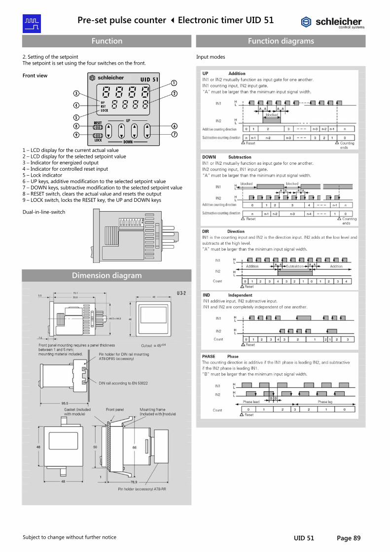
Pre-set pulse counter Electronic timer UID 51
Subject to change without further notice UID 51 Page 89
Function 2. Setting of the setpoint The setpoint is set using the four switches on the front. Front view
1 – LCD display for the current actual value 2 – LCD display for the selected setpoint value 3 – Indicator for energized output 4 – Indicator for controlled reset input 5 – Lock indicator 6 – UP keys, additive modification to the selected setpoint value 7 – DOWN keys, subtractive modification to the selected setpoint value 8 – RESET switch, clears the actual value and resets the output 9 – LOCK switch, locks the RESET key, the UP and DOWN keys
Dual-in-line-switch
Dimension diagram
Function diagrams Input modes
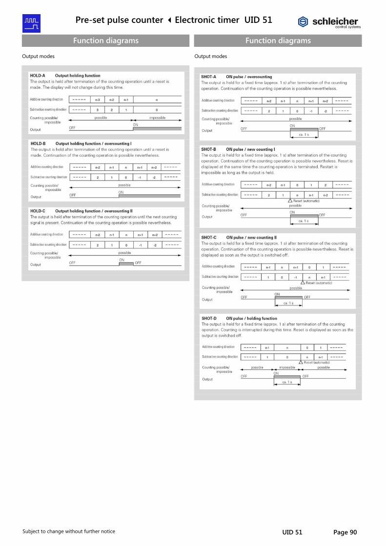
Pre-set pulse counter Electronic timer UID 51
Subject to change without further notice UID 51 Page 90
Function diagrams Output modes
Function diagrams Output modes
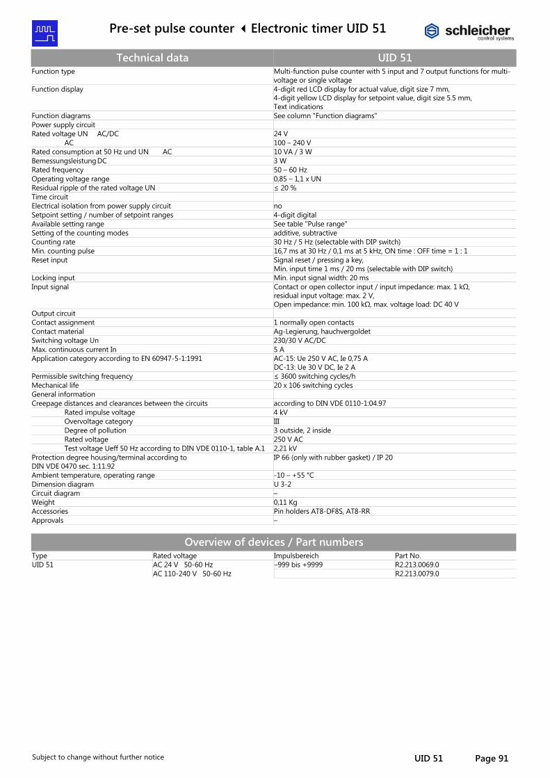
Pre-set pulse counter Electronic timer UID 51
Subject to change without further notice UID 51 Page 91
Technical data UID 51 Function type Multi-function pulse counter with 5 input and 7 output functions for multi-
voltage or single voltage Function display 4-digit red LCD display for actual value, digit size 7 mm,
4-digit yellow LCD display for setpoint value, digit size 5.5 mm, Text indications
Function diagrams See column "Function diagrams" Power supply circuit Rated voltage UN AC/DC 24 V AC 100 – 240 V Rated consumption at 50 Hz und UN AC 10 VA / 3 W Bemessungsleistung DC 3 W Rated frequency 50 – 60 Hz Operating voltage range 0,85 – 1,1 x UN Residual ripple of the rated voltage UN ≤ 20 % Time circuit Electrical isolation from power supply circuit no Setpoint setting / number of setpoint ranges 4-digit digital Available setting range See table "Pulse range" Setting of the counting modes additive, subtractive Counting rate 30 Hz / 5 Hz (selectable with DIP switch) Min. counting pulse 16,7 ms at 30 Hz / 0,1 ms at 5 kHz, ON time : OFF time = 1 : 1 Reset input Signal reset / pressing a key,
Min. input time 1 ms / 20 ms (selectable with DIP switch) Locking input Min. input signal width: 20 ms Input signal Contact or open collector input / input impedance: max. 1 kΩ,
residual input voltage: max. 2 V, Open impedance: min. 100 kΩ, max. voltage load: DC 40 V
Output circuit Contact assignment 1 normally open contacts Contact material Ag-Legierung, hauchvergoldet Switching voltage Un 230/30 V AC/DC Max. continuous current In 5 A Application category according to EN 60947-5-1:1991 AC-15: Ue 250 V AC, Ie 0,75 A
DC-13: Ue 30 V DC, Ie 2 A Permissible switching frequency ≤ 3600 switching cycles/h Mechanical life 20 x 106 switching cycles General information Creepage distances and clearances between the circuits according to DIN VDE 0110-1:04.97 Rated impulse voltage 4 kV Overvoltage category III Degree of pollution 3 outside, 2 inside Rated voltage 250 V AC Test voltage Ueff 50 Hz according to DIN VDE 0110-1, table A.1 2,21 kV Protection degree housing/terminal according to DIN VDE 0470 sec. 1:11.92
IP 66 (only with rubber gasket) / IP 20
Ambient temperature, operating range -10 – +55 °C Dimension diagram U 3-2 Circuit diagram – Weight 0,11 Kg Accessories Pin holders AT8-DF8S, AT8-RR Approvals –
Overview of devices / Part numbers Type Rated voltage Impulsbereich Part No. UID 51 AC 24 V 50-60 Hz –999 bis +9999 R2.213.0069.0 AC 110-240 V 50-60 Hz R2.213.0079.0
![Gira X17 Tap the [OK] button. The timer is set. 1.4.2.3 Deleting a switching time 1 Open the [Timer overview] page. 2 Tap the [Edit] button. 3 Mark the switching time to be deleted](https://img.pdfslide.us/doc/110x75/5fd48a6f95fd8c1ec364f089/gira-x1-7-tap-the-ok-button-the-timer-is-set-1423-deleting-a-switching-time.jpg)