Embed Size (px)
Citation preview
Pacific Division
Time Table
42 General
Employees operating on the Pacific Division must be in possession of this General Time Table. In addition, employees operating within the Vancouver Terminal must be in possession of Time Table No 42 Module 13, and employees operating outside the Vancouver Terminal must be in possession of a Time Table No 42 subdivision module for each subdivision they operate on. Time Table No 42 General and all Modules 1 to 13 Effective at 0001 Wednesday October 14, 2015 Pacific Daylight Time

Time Table No 42 General – October 14, 2015
Page 2/8

Time Table No 42 General – October 14, 2015
Page 3/8
TIME TABLE NO 42 - GENERAL AND ALL MODULES Taking effect at 0001 Wednesday October 14, 2015
Governed by: Pacific Daylight Time: Commencing at 0300 on the second Sunday in March of each year. Pacific Standard Time: Commencing at 0100 on the first Sunday in November of each year.
¡
Time Signal A CP approved time signal (NRC Eastern Time) can be obtained by dialing (800) 363-5409.
TABLE OF CONTENTS Our Foundations ........................................................................................................................................................2 Table of Contents & Pacific Division Module Numbers .............................................................................................3 Pacific Division Map ..................................................................................................................................................4 Contacts – Calgary OC RTC/Directors and CP Police Service .................................................................................5 Trackside Radio System Special Instructions ........................................................................................................ 6-7 Track Diagrams Legend & Time Table Symbols .......................................................................................................8
Subdivision Footnotes are indexed as follows: 0.0 Radio 7.0 Occupancy Control System 1.0 Hot Box Detector System 8.0 Automatic Block Signal System 2.0 Equipment Restrictions 9.0 Public Crossings at Grade 3.0 Dangerous Commodities 10.0 Interlockings 4.0 Speeds 11.0 General Footnotes 5.0 TGBO / DOB Limits 12.0 Spurs and Other Tracks 6.0 Centralized Traffic Control
PACIFIC DIVISION MODULE NUMBERS
Subdivisions Module / Map No Low Mile High Mile Miles
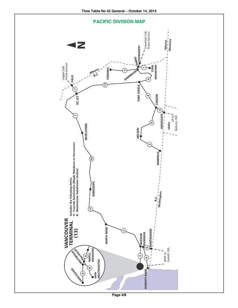
Byron Creek 1 Fabro Coal Mountain 10.0 Cascade 2 North Bend Maple Meadows 106.4 Columbia 3 Nelson End of Track - Warfield 48.0 Cranbrook 4 Crowsnest International Boundary at Kingsgate 158.8 Fording River 5 Sparwood Fording 32.6 Mission 6 Mission Jct Huntingdon 10.1 Mountain 7 Field Revelstoke 125.7 Nelson 8 Curzon Nelson 95.2 Page 9 Riverside Roberts Bank 44.2 Shuswap 10 Revelstoke Kamloops 128.5 Thompson 11 Kamloops North Bend 121.5 Windermere 12 Fort Steele KC Junction 144.8
Terminal Module / Map No Subdivisions, Low and High Mile Miles
Vancouver 13 Cascade Subdivision, Maple Meadows to Vancouver 22.7 Westminster Subdivision, MacAulay to New Westminster 9.2
Time Table No 42 General – October 14, 2015
Page 4/8
PACIFIC DIVISION MAP
Time Table No 42 General – October 14, 2015
Page 5/8
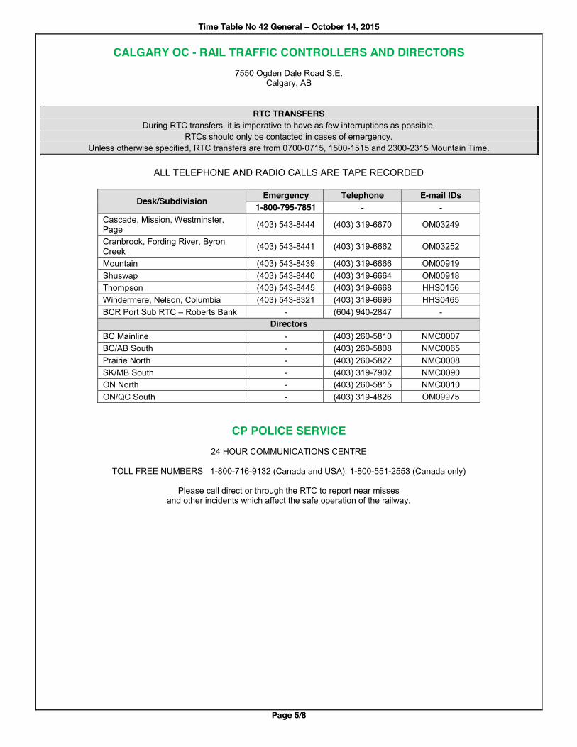
CALGARY OC - RAIL TRAFFIC CONTROLLERS AND DIRECTORS 7550 Ogden Dale Road S.E.
Calgary, AB
RTC TRANSFERS
During RTC transfers, it is imperative to have as few interruptions as possible. RTCs should only be contacted in cases of emergency.
Unless otherwise specified, RTC transfers are from 0700-0715, 1500-1515 and 2300-2315 Mountain Time.
ALL TELEPHONE AND RADIO CALLS ARE TAPE RECORDED
Desk/Subdivision Emergency Telephone E-mail IDs 1-800-795-7851 - -
Cascade, Mission, Westminster, Page (403) 543-8444 (403) 319-6670 OM03249
Cranbrook, Fording River, Byron Creek (403) 543-8441 (403) 319-6662 OM03252
Mountain (403) 543-8439 (403) 319-6666 OM00919 Shuswap (403) 543-8440 (403) 319-6664 OM00918 Thompson (403) 543-8445 (403) 319-6668 HHS0156 Windermere, Nelson, Columbia (403) 543-8321 (403) 319-6696 HHS0465 BCR Port Sub RTC – Roberts Bank - (604) 940-2847 -
Directors BC Mainline - (403) 260-5810 NMC0007 BC/AB South - (403) 260-5808 NMC0065 Prairie North - (403) 260-5822 NMC0008 SK/MB South - (403) 319-7902 NMC0090 ON North - (403) 260-5815 NMC0010 ON/QC South - (403) 319-4826 OM09975
CP POLICE SERVICE 24 HOUR COMMUNICATIONS CENTRE
TOLL FREE NUMBERS 1-800-716-9132 (Canada and USA), 1-800-551-2553 (Canada only)
Please call direct or through the RTC to report near misses
and other incidents which affect the safe operation of the railway.

Time Table No 42 General – October 14, 2015
Page 6/8
TRACKSIDE RADIO SYSTEM SPECIAL INSTRUCTIONS Point to Train System
Type of call: Switch to: Dial: Listen for: (tone) Action: Emergency Call-in to RTC
RTC Call-in Channel
911 "OK" + 8 seconds + "EMERGENCY" Broadcast: "Emergency, Emergency, Emergency". * Return to Train Standby Channel. Wait for RTC to respond.
Normal Call-in to RTC
RTC Call-in Channel
¾(Z)1# "OK" + 8 seconds + "RINGBACK" Return to Train Standby Channel. Wait for RTC to respond.
Normal Call-in to RTC [Alternate procedure]
RTC Call-in Channel
¾(Z)16# "OK" + 8 seconds + "RINGBACK" Switch to RTC Authorities Channel. [if no Authorities Channel, switch to Train Standby Channel] Wait for RTC to respond.
¾(Z)16(L)# for additional information to be added to the call.
Extended Repeater Operation to Utility
RTC Call-in Channel
¾(Z)2XXX# "OK" + 8 seconds + "RINGING" + "EXT RPTR CONNECT"
Switch to Train Standby Channel. Voice call person being called. Switch to RTC Call-in Channel and dial ¾(Z)# to disconnect.
Utility System Type of call: Switch to: Dial: Listen for: (tone) Action: Emergency Call-in to RTC
Utility Channel 911 "OK" + 8 seconds + "EMERGENCY" Broadcast: "Emergency, Emergency, Emergency". * Wait for RTC to respond.
Normal Call-in to RTC Utility Channel ¾(Z)1# "OK" + 8 seconds + "RINGBACK" Wait for RTC to respond. Normal Call-in to RTC [Alternate procedure] NOTE - not available on subdivisions with System 2 in effect**
Utility Channel ¾(Z)16# "OK" + 8 seconds + "RINGBACK" Wait for RTC to respond. ¾(Z)16(L)# for additional information to be added to the call.
Local Repeater Operation
Utility Channel ¾(Z)XXX# "OK" Voice call person being called. Dial ¾(Z)# to disconnect.
Extended Repeater Operation to Utility
Utility Channel ¾(Z)2XXX# "OK" + 8 seconds + "RINGING" + "EXT RPTR CONNECT"
Voice call person being called. Dial ¾(Z)# to disconnect.
Extended Repeater Operation to Point to Train
Utility Channel ¾(Z)2XXX# "OK" + 8 seconds + "RINGING" + "EXT RPTR CONNECT"
Voice call person being called. Dial ¾(Z)# to disconnect.
* You have 10 seconds to make this broadcast. ** Mission, Page, and Thompson Subdivisions; and Vancouver Terminal.

Time Table No 42 General – October 14, 2015
Page 7/8
TRACKSIDE RADIO SYSTEM SPECIAL INSTRUCTIONS Radio Telephone Interface (RTI) System (See RTI Notes)
Type of call: Switch to: Dial: Listen for: (tone) Action: Emergency Call-in to RTC
Utility Channel** ¾¾XXX9# "OK" + 8 seconds +
"RINGING" Wait for RTC to respond.
Normal Call-in to RTC Utility Channel** ¾¾XXX1# "OK" + 8 seconds +
"Voice Instructions" Follow Voice Instructions. Wait for RTC to respond.
Engineering Service Reliability
Utility Channel** ¾¾XXX4# "OK" + 8 seconds +
"Voice Instructions" Follow Voice Instructions. Dial ¾(Z)# to disconnect.
** If a Utility Channel is not provided, use the Train Standby Channel. When using the Train Standby Channel you must wait for the voice message to end before selecting your choice. Failure to do so will result in a call-in failure.
Notes Train Standby and Maintenance of Way channels, Point to Train and Utility RTC Call-in Channels and tower codes are indicated in subdivision station columns. Zone Codes and instructions to contact Engineering Service Reliability are indicated in subdivi-sion footnotes. Radio Telephone Interface (RTI) System The RTI is a backup communication system between office and field, and should only be used when you hear a "Call Failed" tone when trying to call-in, or when instructed to do so. It must be used when participating in a planned exercise at CP's Busi-ness Continuity Facility (BCF). Codes "(L)" ........ denotes a number for additional information to be added to call as follows: 1 - Request TOP 2 - Cancel TOP 3 - Information required 4 - Switch or Snow Melter operation required 5 - Restored switch 6 - Investigate UTO 9 - Parks Canada. "(Z)" ........ denotes Zone Code indicated in Subdivision footnotes. "XXX" ..... denotes Tower Code as indicated in Subdivision station columns (nearest tower or tower you wish to connect to). System Radio Tones "OK" (2 short beeps) ................................................ call has reached radio tower "RINGBACK" (3 short rings) ..................................... call has reached RTC's console "EMERGENCY" (2 second continuous) ................... call has reached RTC's console "RINGING" (normal telephone ring) ......................... RTI call is progressing "BUSY" (busy signal) ............................................... system is busy "EXT RPTR CONNECT" (1 second continuous) ...... extended repeater is enabled for use "INVALID" (9 short beeps)........................................ invalid destination called "CALL FAILED" (hi-lo or bee-bop) ............................ radio site is inoperative On subdivisions with System 2 in effect, several tones are different as follows: "RINGBACK" (single telephone ring) ....................... call has reached RTC's console "INVALID" (hi-lo or bee-bop) .................................... invalid destination called "CALL FAILED" (9 short beeps) ............................... radio site is inoperative

Time Table No 42 General – October 14, 2015
Page 8/8
TIME TABLE SYMBOLS
The following symbols when used in the time table indicate: B Operating bulletins C Cautionary limits D Trains or Transfers report departure to RTC S Special Derail X Crossover between main tracks Y Wye * See footnote + Interlocking - see footnotes

Pacific Division Time Table No 42, Module 2 Cascade Subdivision – Effective at 0001 October 14, 2015
Page 1/5
Train
Stan
dby
Chan
nel
Point
to T
rain
Towe
r Cod
e
RTC
Call-i
n Cha
nnel
& RT
C Ca
ll-in C
ode
RTC
Autho
rities
Ch
anne
l
Emer
genc
y Ca
ll-in
Cod
e
Utilit
y Cha
nnel
and
RTC
Call-i
n Cod
e
Utilit
y Tow
er C
ode
Maint
enan
ce of
Way
Ch
anne
l
Miles
from
Nor
th Be
nd
WES
TWAR
D CASCADE SUBDIVISION (Subdivision No 6003)
TrAM Area 1 west of Katz, Area 2 east of Katz
EAST
WAR
D
Main
Trac
k(s)
Metho
d of C
ontro
l TG
BO / D
OB Li
mits
Sidin
g Cap
acity
in F
eet
Sign
alled
Sidi
ng
Stati
on N
umbe
r
STATIONS
CP 4
67-67
2051
CP 9
21-67
¾51#
CP 5
81-81 911
CP 23
09-93
¾51#
2151
CP 19
93-93
0.0 NORTH BEND Y
1
TGBO
Yard 9655
2.1 2.1
MOLLISON 9767
6.2 4.1
CHINA BAR
9656 2052 2152 15.5
9.3 SPUZZUM
7175 9658 2053 2153
22.0 6.5
SADDLE ROCK
9660 2054 2154 29.0
7.0 YALE S
9661
2055 2155 35.6
6.6 CHOATE
8010 9662
2056 2156 44.9 9.3
KATZ
51.7 6.8
RUBY CREEK
9666
CP 1
91-91
2071
CP 3
21-91
¾61#
CP 12
15-49
¾61#
2171
CP 11
49-49
58.9 7.2
AGASSIZ
2 CTC
9668
63.1 4.2
MAGELLAN X
9667
68.2 5.1
Interlocked Drawbridge
72.3 4.1
DEROCHE X
9670 2072 2172
83.9 11.6
HATZIC X
9673
2073 2173
87.0
3.1 MISSION JCT
Jct Mission Sub XY
DOB
9675
87.9 0.9
MISSION WEST X
9653 2074 2174 94.5
6.6 RUSKIN X
9677
2075 2175 99.5
5.0 ALBION X
9679
101.3 1.8
RIVER ROAD X
9664
103.0 1.7
HANEY
9681 2076 2176
106.4 3.4
MAPLE MEADOWS
X
9689
Vancouver Terminal Module
107.5
1.1 ONDERDONK
Vancouver Terminal Module
109.4 1.9
PITT RIVER
9680
109.7 0.3
Interlocked Drawbridge
110.0 0.3
SMITH 9654
111.9 1.9
PORT COQUITLAM 9684
112.4
0.5 MacAULAY
Jct Westminster Sub 9688
112.9 0.5
WESTWOOD 9766
114.1 1.2
SETO
115.6 1.5
PORT MOODY 9693
117.6 2.0
CASSIN 9657
120.5 2.9
BARNET 9695
124.1 3.6
SECOND NARROWS 9705
125.7 1.6
RENFREW 9781
126.9 1.2
WILLISTON 9774
127.7
0.8 HEATLEY
Interlocked Railway Crossing
9769
128.3 0.6
DUNLEVY 9768
129.1 0.8
VANCOUVER
9700
+
Pacific Division Time Table No 42, Module 2 Cascade Subdivision – Effective at 0001 October 14, 2015
Page 2/5
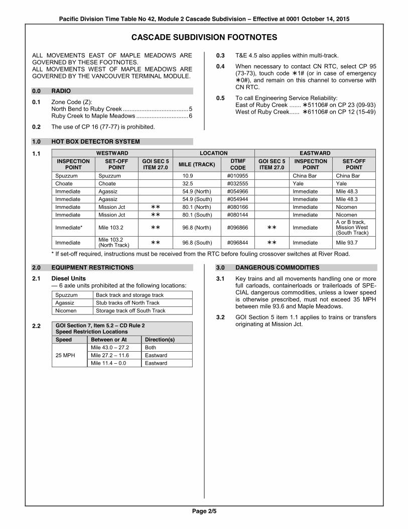
CASCADE SUBDIVISION FOOTNOTES
ALL MOVEMENTS EAST OF MAPLE MEADOWS ARE GOVERNED BY THESE FOOTNOTES. ALL MOVEMENTS WEST OF MAPLE MEADOWS ARE GOVERNED BY THE VANCOUVER TERMINAL MODULE.
0.0 RADIO 0.1 Zone Code (Z):
North Bend to Ruby Creek ....................................... 5 Ruby Creek to Maple Meadows ............................... 6
0.2 The use of CP 16 (77-77) is prohibited.
0.3 T&E 4.5 also applies within multi-track.
0.4 When necessary to contact CN RTC, select CP 95 (73-73), touch code ¾1# (or in case of emergency ¾0#), and remain on this channel to converse with CN RTC.
0.5 To call Engineering Service Reliability: East of Ruby Creek ....... ¾51106# on CP 23 (09-93) West of Ruby Creek ...... ¾61106# on CP 12 (15-49)
1.0 HOT BOX DETECTOR SYSTEM
1.1 WESTWARD LOCATION EASTWARD
INSPECTION
POINT SET-OFF
POINT GOI SEC 5 ITEM 27.0 MILE (TRACK) DTMF
CODE GOI SEC 5 ITEM 27.0
INSPECTION POINT
SET-OFF POINT
Spuzzum Spuzzum 10.9 #010955 China Bar China Bar Choate Choate 32.5 #032555 Yale Yale Immediate Agassiz 54.9 (North) #054966 Immediate Mile 48.3 Immediate Agassiz 54.9 (South) #054944 Immediate Mile 48.3 Immediate Mission Jct ¾¾ 80.1 (North) #080166 Immediate Nicomen Immediate Mission Jct ¾¾ 80.1 (South) #080144 Immediate Nicomen
Immediate* Mile 103.2 ¾¾ 96.8 (North) #096866 ¾¾ Immediate A or B track, Mission West (South Track)
Immediate Mile 103.2 (North Track) ¾¾ 96.8 (South) #096844 ¾¾ Immediate Mile 93.7
* If set-off required, instructions must be received from the RTC before fouling crossover switches at River Road. 2.0 EQUIPMENT RESTRICTIONS 2.1 Diesel Units
— 6 axle units prohibited at the following locations: Spuzzum Back track and storage track Agassiz Stub tracks off North Track Nicomen Storage track off South Track
2.2 GOI Section 7, Item 5.2 – CD Rule 2
Speed Restriction Locations Speed Between or At Direction(s)
25 MPH Mile 43.0 – 27.2 Both
Mile 27.2 – 11.6 Eastward Mile 11.4 – 0.0 Eastward
3.0 DANGEROUS COMMODITIES 3.1 Key trains and all movements handling one or more
full carloads, containerloads or trailerloads of SPE-CIAL dangerous commodities, unless a lower speed is otherwise prescribed, must not exceed 35 MPH between mile 93.6 and Maple Meadows.
3.2 GOI Section 5 item 1.1 applies to trains or transfers originating at Mission Jct.
Pacific Division Time Table No 42, Module 2 Cascade Subdivision – Effective at 0001 October 14, 2015
Page 3/5
CASCADE SUBDIVISION FOOTNOTES
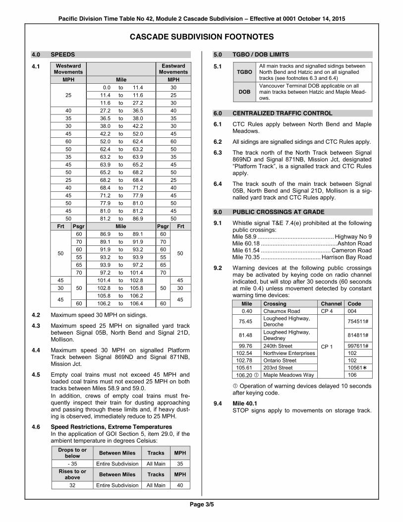
4.0 SPEEDS
4.1 Westward Movements Eastward
Movements MPH Mile MPH
25 0.0 to 11.4 30
11.4 to 11.6 25 11.6 to 27.2 30 40 27.2 to 36.5 40 35 36.5 to 38.0 35 30 38.0 to 42.2 30 45 42.2 to 52.0 45 60 52.0 to 62.4 60 50 62.4 to 63.2 50 35 63.2 to 63.9 35 45 63.9 to 65.2 45 50 65.2 to 68.2 50 25 68.2 to 68.4 25 40 68.4 to 71.2 40 45 71.2 to 77.9 45 50 77.9 to 81.0 50 45 81.0 to 81.2 45 50 81.2 to 86.9 50 Frt Psgr Mile Psgr Frt
50
60 86.9 to 89.1 60
50
70 89.1 to 91.9 70 60 91.9 to 93.2 60 55 93.2 to 93.9 55 65 93.9 to 97.2 65 70 97.2 to 101.4 70 45
50 101.4 to 102.8
50 45
30 102.8 to 105.8 30
45 105.8 to 106.2
45 60 106.2 to 106.4 60
4.2 Maximum speed 30 MPH on sidings.
4.3 Maximum speed 25 MPH on signalled yard track between Signal 05B, North Bend and Signal 21D, Mollison.
4.4 Maximum speed 30 MPH on signalled Platform Track between Signal 869ND and Signal 871NB, Mission Jct.
4.5 Empty coal trains must not exceed 45 MPH and loaded coal trains must not exceed 25 MPH on both tracks between Miles 58.9 and 59.0. In addition, crews of empty coal trains must fre-quently inspect their train for dusting approaching and passing through these limits and, if heavy dust-ing is observed, immediately reduce to 25 MPH.
4.6 Speed Restrictions, Extreme Temperatures In the application of GOI Section 5, item 29.0, if the ambient temperature in degrees Celsius:
Drops to or below Between Miles Tracks MPH
- 35 Entire Subdivision All Main 35
Rises to or above Between Miles Tracks MPH
32 Entire Subdivision All Main 40
5.0 TGBO / DOB LIMITS
5.1 TGBO
All main tracks and signalled sidings between North Bend and Hatzic and on all signalled tracks (see footnotes 6.3 and 6.4)
DOB
Vancouver Terminal DOB applicable on all main tracks between Hatzic and Maple Mead-ows.
6.0 CENTRALIZED TRAFFIC CONTROL 6.1 CTC Rules apply between North Bend and Maple
Meadows.
6.2 All sidings are signalled sidings and CTC Rules apply.
6.3 The track north of the North Track between Signal 869ND and Signal 871NB, Mission Jct, designated “Platform Track”, is a signalled track and CTC Rules apply.
6.4 The track south of the main track between Signal 05B, North Bend and Signal 21D, Mollison is a sig-nalled yard track and CTC Rules apply.
9.0 PUBLIC CROSSINGS AT GRADE
9.1 Whistle signal T&E 7.4(e) prohibited at the following public crossings: Mile 58.9 .............................................. Highway No 9 Mile 60.18 .............................................. Ashton Road Mile 61.54 .......................................... Cameron Road Mile 70.35 .................................... Harrison Bay Road
9.2 Warning devices at the following public crossings may be activated by keying code on radio channel indicated, but will stop after 30 seconds (60 seconds at mile 0.4) unless movement detected by constant warning time devices:
Mile Crossing Channel Code 0.40 Chaumox Road CP 4 004
75.45 Lougheed Highway, Deroche
9.3 CP 1
754511#
81.48 Lougheed Highway, Dewdney 814811#
99.76 240th Street 997611# 102.54 Northview Enterprises 102 102.78 Ontario Street 102 105.61 203rd Street 10561¾ 106.20 c Maple Meadows Way 106
c Operation of warning devices delayed 10 seconds after keying code.
9.4 Mile 40.1 STOP signs apply to movements on storage track.
Pacific Division Time Table No 42, Module 2 Cascade Subdivision – Effective at 0001 October 14, 2015
Page 4/5
CASCADE SUBDIVISION FOOTNOTES
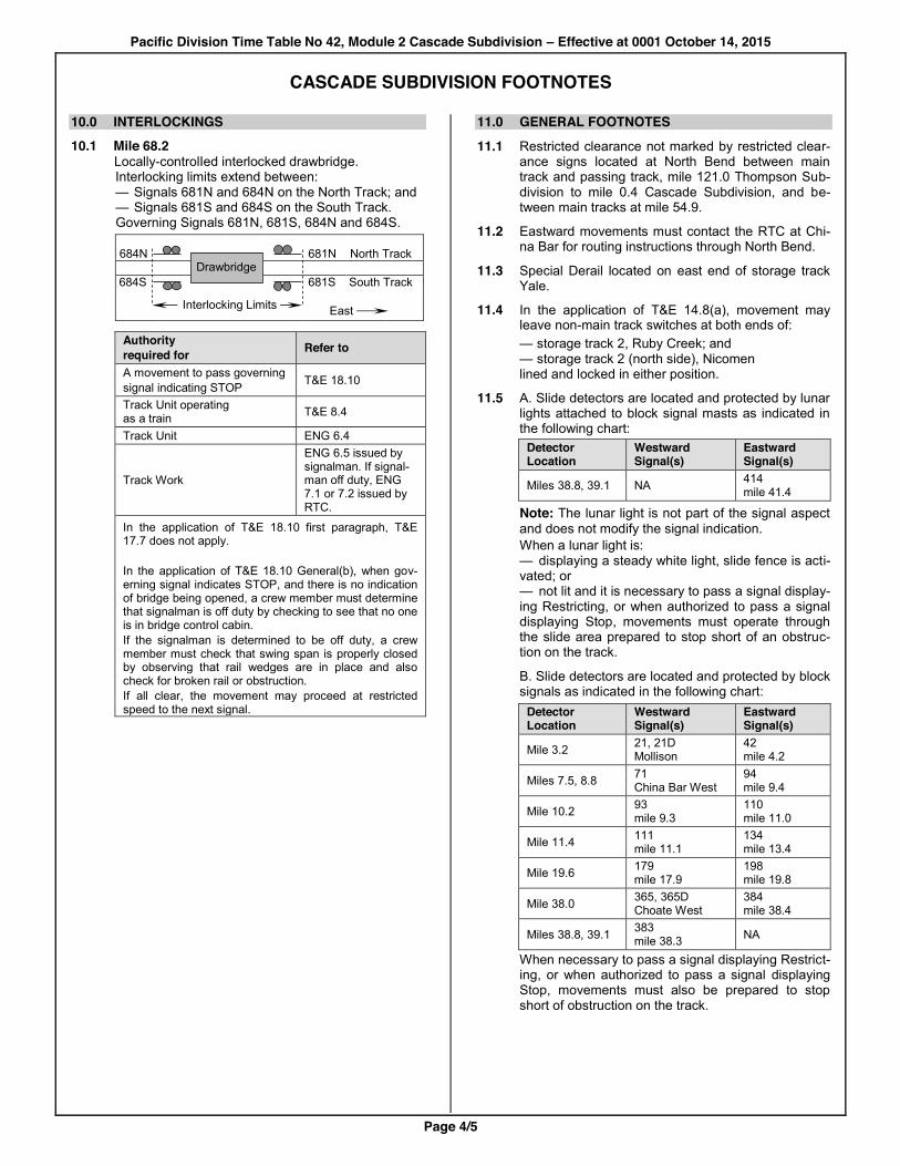
10.0 INTERLOCKINGS 10.1 Mile 68.2
Locally-controlIed interlocked drawbridge. Interlocking limits extend between: — Signals 681N and 684N on the North Track; and — Signals 681S and 684S on the South Track. Governing Signals 681N, 681S, 684N and 684S.
684N 681N North Track 684S 681S South Track
Interlocking Limits
East
Authority required for Refer to
A movement to pass governing signal indicating STOP T&E 18.10
Track Unit operating as a train T&E 8.4
Track Unit ENG 6.4
Track Work
ENG 6.5 issued by signalman. If signal-man off duty, ENG 7.1 or 7.2 issued by RTC.
In the application of T&E 18.10 first paragraph, T&E 17.7 does not apply. In the application of T&E 18.10 General(b), when gov-erning signal indicates STOP, and there is no indication of bridge being opened, a crew member must determine that signalman is off duty by checking to see that no one is in bridge control cabin. If the signalman is determined to be off duty, a crew member must check that swing span is properly closed by observing that rail wedges are in place and also check for broken rail or obstruction. If all clear, the movement may proceed at restricted speed to the next signal.
11.0 GENERAL FOOTNOTES 11.1 Restricted clearance not marked by restricted clear-
ance signs located at North Bend between main track and passing track, mile 121.0 Thompson Sub-division to mile 0.4 Cascade Subdivision, and be-tween main tracks at mile 54.9.
11.2 Eastward movements must contact the RTC at Chi-na Bar for routing instructions through North Bend.
11.3 Special Derail located on east end of storage track Yale.
11.4 In the application of T&E 14.8(a), movement may leave non-main track switches at both ends of: — storage track 2, Ruby Creek; and — storage track 2 (north side), Nicomen lined and locked in either position.
11.5 A. Slide detectors are located and protected by lunar lights attached to block signal masts as indicated in the following chart:
Detector Location
Westward Signal(s)
Eastward Signal(s)
Miles 38.8, 39.1 NA 414 mile 41.4
Note: The lunar light is not part of the signal aspect and does not modify the signal indication. When a lunar light is: — displaying a steady white light, slide fence is acti-vated; or — not lit and it is necessary to pass a signal display-ing Restricting, or when authorized to pass a signal displaying Stop, movements must operate through the slide area prepared to stop short of an obstruc-tion on the track.
B. Slide detectors are located and protected by block signals as indicated in the following chart:
Detector Location
Westward Signal(s)
Eastward Signal(s)
Mile 3.2 21, 21D Mollison
42 mile 4.2
Miles 7.5, 8.8 71 China Bar West
94 mile 9.4
Mile 10.2 93 mile 9.3
110 mile 11.0
Mile 11.4 111 mile 11.1
134 mile 13.4
Mile 19.6 179 mile 17.9
198 mile 19.8
Mile 38.0 365, 365D Choate West
384 mile 38.4
Miles 38.8, 39.1 383 mile 38.3 NA
When necessary to pass a signal displaying Restrict-ing, or when authorized to pass a signal displaying Stop, movements must also be prepared to stop short of obstruction on the track.
Drawbridge
Pacific Division Time Table No 42, Module 2 Cascade Subdivision – Effective at 0001 October 14, 2015
Page 5/5
CASCADE SUBDIVISION FOOTNOTES
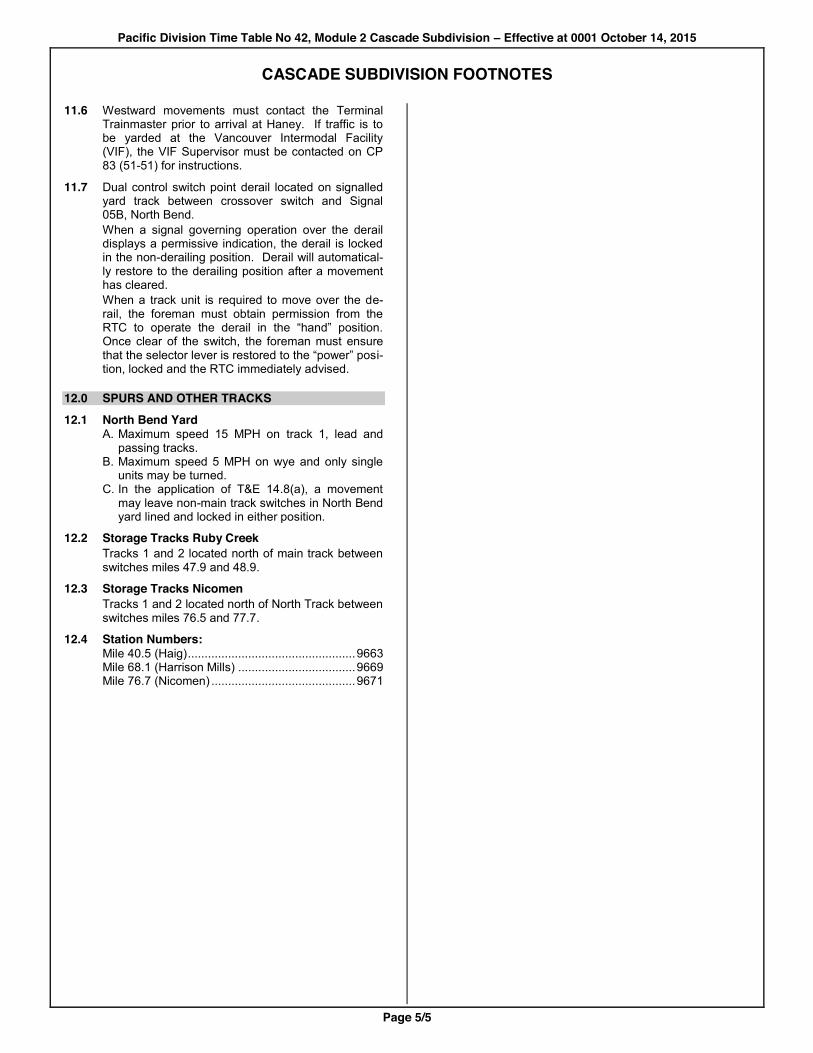
11.6 Westward movements must contact the Terminal Trainmaster prior to arrival at Haney. If traffic is to be yarded at the Vancouver Intermodal Facility (VIF), the VIF Supervisor must be contacted on CP 83 (51-51) for instructions.
11.7 Dual control switch point derail located on signalled yard track between crossover switch and Signal 05B, North Bend. When a signal governing operation over the derail displays a permissive indication, the derail is locked in the non-derailing position. Derail will automatical-ly restore to the derailing position after a movement has cleared. When a track unit is required to move over the de-rail, the foreman must obtain permission from the RTC to operate the derail in the “hand” position. Once clear of the switch, the foreman must ensure that the selector lever is restored to the “power” posi-tion, locked and the RTC immediately advised.
12.0 SPURS AND OTHER TRACKS 12.1 North Bend Yard
A. Maximum speed 15 MPH on track 1, lead and passing tracks.
B. Maximum speed 5 MPH on wye and only single units may be turned.
C. In the application of T&E 14.8(a), a movement may leave non-main track switches in North Bend yard lined and locked in either position.
12.2 Storage Tracks Ruby Creek Tracks 1 and 2 located north of main track between switches miles 47.9 and 48.9.
12.3 Storage Tracks Nicomen Tracks 1 and 2 located north of North Track between switches miles 76.5 and 77.7.
12.4 Station Numbers: Mile 40.5 (Haig) .................................................. 9663 Mile 68.1 (Harrison Mills) ................................... 9669 Mile 76.7 (Nicomen) ........................................... 9671


Time Table No 42, Module 13 Vancouver Terminal – Effective at 0001 October 14, 2015
Page 1/9
Trai
n St
andb
y
Chan
nel
Point
to T
rain
Towe
r Cod
e
RTC
Call-
in C
hann
el
and
RTC
Call-
in C
ode
RTC
Auth
ority
Cha
nnel
Emer
genc
y Ca
ll-in
Cod
e
Utilit
y Ch
anne
l and
RT
C Ca
ll-in
Cod
e
Utilit
y To
wer C
ode
Main
tena
nce
of W
ay
Chan
nel
D L
Zone
G
OI S
ec 1
0 ite
m 5
.4
Subd
ivisio
n M
ileag
e VANCOUVER TERMINAL
TrAM Area 1
Main
Tra
ck(s
)
Met
hod
of C
ontro
l
TGBO
/ DO
B Lim
its
Sidi
ng C
apac
ity in
Fee
t Si
gnal
led S
iding
Stat
ion N
umbe
r
STATIONS
CP 78
41-41
2081
CP 10
21-41
¾71#
CP 5
81-81 911
CP 18
35-71
¾71#
2181
CP 13
71-71
CASCADE SUBDIVISION 106.4 106.4 MAPLE MEADOWS X
2
CT
C DOB
9689
107.5 1.1
ONDERDONK
109.4 1.9
PITT RIVER X 9680
109.7 0.3
Interlocked Drawbridge
110.0 0.3
SMITH X 9654
111.9 1.9
PORT COQUITLAM BX Yard 9684
112.4 0.5
MacAULAY Jct Westminster Sub
XY
9688
112.9 0.5
WESTWOOD X 9766
114.1 1.2
SETO
2083 2183
115.6 1.5
PORT MOODY SXY 9693
117.6 2.0
CASSIN X 9657
120.5 2.9
BARNET X 9695
124.1 3.6
SECOND NARROWS X 9705
2084 2184
125.7 1.6
RENFREW
1
9781
126.9 1.2
WILLISTON B Yard 9774
127.7 0.8
HEATLEY Interlocked Railway Crossing
9769
128.3 0.6
DUNLEVY
9768
129.1 0.8
VANCOUVER
Yard
9700
2081 2181
WESTMINSTER SUBDIVISION 0.0 MacAULAY
Jct Cascade Sub Y
1 CTC
DOB
9688
0.4 0.4
KINGSWAY
9784
2.5 2.1
MAYFAIR
9715
3.5 1.0
BOOTH
9733
2082 2182
4.9 1.4
FRASER MILLS
9718
5.6 5.6 0.7
SAPPERTON Connection to BNSF
9719
6.8 1.2
CUMBERLAND Connection to BNSF
NMT
9.2 2.4
NEW WESTMINSTER 9720
VANCOUVER TERMINAL FOOTNOTES
ALL MOVEMENTS IN THE VANCOUVER TERMINAL ARE GOVERNED BY THESE FOOTNOTES.
Vancouver Terminal
Subdivision All tracks between Cascade Maple Meadows and Vancouver Westminster MacAulay and New Westminster
+
+
Time Table No 42, Module 13 Vancouver Terminal – Effective at 0001 October 14, 2015
Page 2/9
VANCOUVER TERMINAL FOOTNOTES
0.0 RADIO 0.1 Zone Code (Z) is 7.
0.2 T&E 4.5 also applies within multi-track.
0.3 The use of CP 16 (77-77) is prohibited.
0.4 Spectra “DISP” feature does not apply.
0.5 Eastward freight trains at, and leaving Port Coquit-lam, must monitor both CP 1 (91-91) and CP 78 (41-41), until departure from Maple Meadows.
0.6 Movements on CP track at Sapperton must monitor CP 78 (41-41) at all times.
0.7 To call Engineering Service Reliability, dial ¾71106# on CP 18 (35-71).
0.8 Tower Codes for the Marpole radio tower are 2085 for Train Standby Channel and 2185 for Utility Channel.
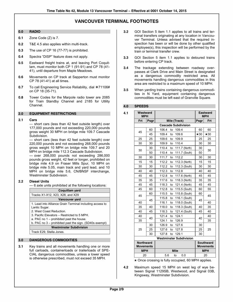
2.0 EQUIPMENT RESTRICTIONS 2.1 Cars
— short cars (less than 42 feet outside length) over 177,000 pounds and not exceeding 220,000 pounds gross weight 30 MPH on bridge mile 109.7 Cascade Subdivision. — short cars (less than 42 feet outside length) over 220,000 pounds and not exceeding 268,000 pounds gross weight 10 MPH on bridge mile 109.7 and 20 MPH on bridge mile 112.3 Cascade Subdivision. — over 268,000 pounds not exceeding 286,000 pounds gross weight, 42 feet or longer, prohibited on bridge mile 4.9 on Fraser Mills Spur, 10 MPH on bridge mile 5.05, main track and yard lead, and 10 MPH on bridge mile 5.6, CN/BNSF interchange, Westminster Subdivision.
2.2 Diesel Units — 6 axle units prohibited at the following locations:
Coquitlam yard Tracks X1-X12, X23, X28, and X29
Vancouver yard 1. Lead into Alliance Grain Terminal including access to Lantic Sugar. 2. West Coast Reduction. 3. Pacific Elevators – Restricted to 5 MPH. a. PAC no 1 – prohibited past the house. b. PAC no 3 – prohibited past the sign. (SD40s exempt)
Westminster Subdivision Track E29, Stella Jones.
3.0 DANGEROUS COMMODITIES
3.1 Key trains and all movements handling one or more full carloads, containerloads or trailerloads of SPE-CIAL dangerous commodities, unless a lower speed is otherwise prescribed, must not exceed 35 MPH.
3.2 GOI Section 5 item 1.1 applies to all trains and ter-minal transfers originating at any location in Vancou-ver Terminal. Unless advised that the required in-spection has been or will be done by other qualified employee(s), this inspection will be performed by the train or terminal transfer crew.
3.3 GOI Section 5 item 1.1 applies to detoured trains before entering CP track.
3.4 The trackage extending between roadway over-passes at Clark Drive and Main Street is designated as a dangerous commodity restricted area. All movements handling dangerous commodities in this area are restricted to a maximum speed of 10 MPH.
3.5 When yarding trains containing dangerous commodi-ties in N Yard, equipment containing dangerous commodities must be left east of Granville Square.
4.0 SPEEDS
4.1 Westward MPH Eastward
MPH Frt Psgr Mile (Track) Psgr Frt Cascade Subdivision
45 60 106.4 to 109.4 60 60
45 109.4 to 109.6 30 30 25 25 109.6 to 109.9 25 25 30 30 109.9 to 110.4 30 30
30 30 110.4 to 111.7 (North) 30
30 50 110.4 to 111.7 (South) 50 30 30 111.7 to 112.2 30 30 15 15 112.2 to 112.3 (North) 15 15 30 30 112.2 to 112.3 (South) 30 30 40 40 112.3 to 112.8 40 40 45 45 112.8 to 117.6 (North) 45 45 35 35 117.6 to 118.3 (North) 35 35 45 45 118.3 to 121.4 (North) 45 45 45 60 112.8 to 115.5 (South) 60 55
45 60 115.5 to 115.8 (South) 60
45 45
115.8 to 116.1 (South) 45 40 116.1 to 118.0 (South) 40
35 40 118.0 to 118.3 (South) 40 35 40 45 118.3 to 121.4 (South) 45 40 40
40 121.4 to 124.1
40 40
35 124.1 to 126.9 35
25 30 126.9 to 127.6 30
25 25 127.6 to 127.8 25 30 127.8 to 129.1 30 Westminster Subdivision
Northward Movements Southward
Movements MPH Mile MPH 20 5.6 to 0.0 20
Once crossing is fully occupied, 60 MPH applies.
4.2 Maximum speed 15 MPH on west leg of wye be-tween Signal 1129SB, Westwood, and Signal 03B, Kingsway, Westminster Subdivision.

Time Table No 42, Module 13 Vancouver Terminal – Effective at 0001 October 14, 2015
Page 3/9
VANCOUVER TERMINAL FOOTNOTES
5.0 TGBO / DOB LIMITS 5.1 Vancouver Terminal DOB applicable on all main
tracks and signalled tracks (see Footnotes 6.3, 6.4 and 6.5) in Vancouver Terminal.
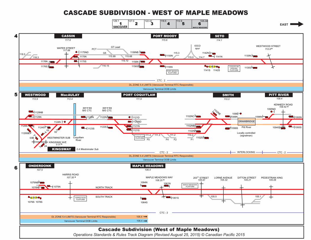
6.0 CENTRALIZED TRAFFIC CONTROL 6.1 CTC Rules apply on Cascade Subdivision between
Maple Meadows and Vancouver, except on North Track between: — Signal 1096N, Pitt River and Signal 1099N, Smith; — Signal 1122N, Port Coquitlam and Signal 1123N, MacAulay.
6.2 CTC Rules apply on Westminster Subdivision be-tween MacAulay and Sapperton.
6.3 The tracks north of the Cascade Subdivision main track between: — Signal 1257D and Signal 1258B, Renfrew; — Signal 1269D and Signal 1270B, Williston; — Signal 1283D and Signal 1284D, Dunlevy; are signalled yard tracks and CTC Rules apply. ENG 7.2 does not apply.
6.4 The west leg of the wye between Signal 1129SB, Westwood and Signal 03B, Kingsway, Westminster Subdivision, is a signalled track and CTC Rules apply.
6.5 The track west of the Westminster Subdivision main track between Signal 55B and Signal 56B, Sapper-ton is a signalled track and CTC Rules apply. ENG 7.2 does not apply.
6.6 When dual control switches at Port Coquitlam and Smith are referenced in a CTC authority, they may be identified with a number as per the diagram be-low.
Port Coquitlam
1
2
2 3
North Track
South Track
West
Port Coquitlam
1
2
2 3
North Track
South Track
5
1 3 4
5 2
Smith
2
North Track
South Track
West
9.0 PUBLIC CROSSINGS AT GRADE 9.1 Whistle signal T&E 7.4(e) prohibited at the following
public crossings: Cascade Subdivision Mile 107.35 ............................................. Harris Road Mile 112.80 ..................................... Westwood Street Westminster Subdivision Mile 1.52 ............................................ Pitt River Road
9.2 Warning devices at the following public crossings may be activated by keying the appropriate code on CP 78 (41-41), but will stop after 30 seconds unless movement detected by constant warning time devic-es:
Mile Subdivision Crossing Code 107.35 Cascade Harris Road 107 109.42† Cascade Kennedy Road 109 112.80 Cascade Westwood St. 112811#
0.37 Westminster Kingsway Ave 037 1.52 Westminster Pitt River Road 01521 5.87 Westminster Braid Street 05871¾
† Westward movements on non-main track must stop at STOP sign, then operate warning devices, before fouling crossing. Warning devices will stop after 40 seconds unless movement occupies track circuit.
9.3 Mile 0.37 Westminster Subdivision, Kingsway Avenue Northward movements longer than 1500 feet ap-proaching Signal 04 Kingsway displaying Clear to Stop or Slow to Stop, must stop within 200 feet of signal. Operation of warning devices will stop after 30 seconds. Once Signal 04 changes to Clear to Slow, Slow to Slow, or Restricting, a crew member must key 037 on CP 78 (41-41). After approximately 12 seconds the crossing warning devices will start to operate.
Time Table No 42, Module 13 Vancouver Terminal – Effective at 0001 October 14, 2015
Page 4/9
VANCOUVER TERMINAL FOOTNOTES
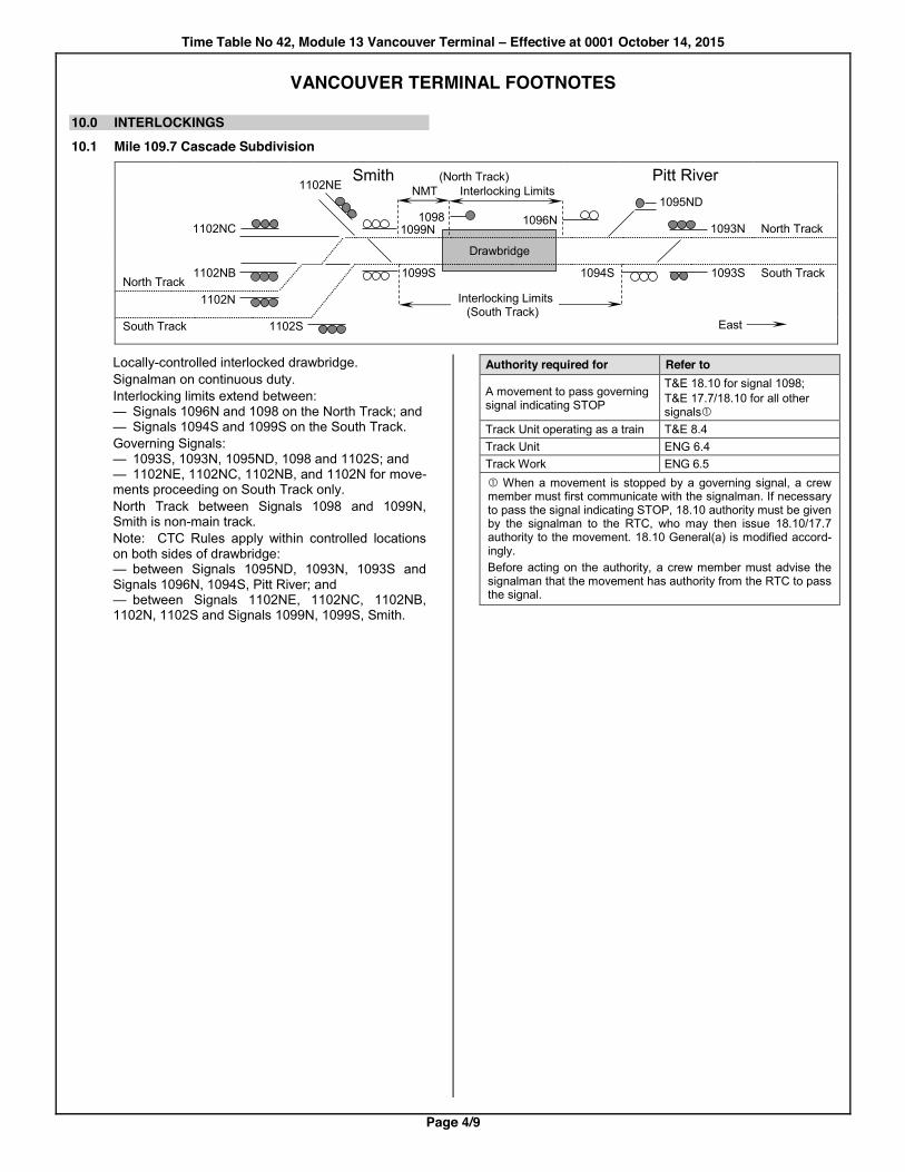
10.0 INTERLOCKINGS10.1 Mile 109.7 Cascade Subdivision
Smith (North Track) NMT Interlocking Limits
Pitt River 1102NE
1095ND 1102NC
1098 1099N 1096N
1093N North Track
Drawbridge
North Track 1102NB 1099S 1094S 1093S South Track
1102N Interlocking Limits
(South Track) South Track 1102S
East
Locally-controlled interlocked drawbridge. Signalman on continuous duty. Interlocking limits extend between: — Signals 1096N and 1098 on the North Track; and — Signals 1094S and 1099S on the South Track. Governing Signals: — 1093S, 1093N, 1095ND, 1098 and 1102S; and — 1102NE, 1102NC, 1102NB, and 1102N for move-ments proceeding on South Track only. North Track between Signals 1098 and 1099N, Smith is non-main track. Note: CTC Rules apply within controlled locations on both sides of drawbridge: — between Signals 1095ND, 1093N, 1093S and Signals 1096N, 1094S, Pitt River; and — between Signals 1102NE, 1102NC, 1102NB, 1102N, 1102S and Signals 1099N, 1099S, Smith.
Authority required for Refer to
A movement to pass governing signal indicating STOP
T&E 18.10 for signal 1098; T&E 17.7/18.10 for all other signalsc
Track Unit operating as a train T&E 8.4 Track Unit ENG 6.4 Track Work ENG 6.5 c When a movement is stopped by a governing signal, a crew member must first communicate with the signalman. If necessary to pass the signal indicating STOP, 18.10 authority must be given by the signalman to the RTC, who may then issue 18.10/17.7 authority to the movement. 18.10 General(a) is modified accord-ingly. Before acting on the authority, a crew member must advise the signalman that the movement has authority from the RTC to pass the signal.
Time Table No 42, Module 13 Vancouver Terminal – Effective at 0001 October 14, 2015
Page 5/9
VANCOUVER TERMINAL FOOTNOTES
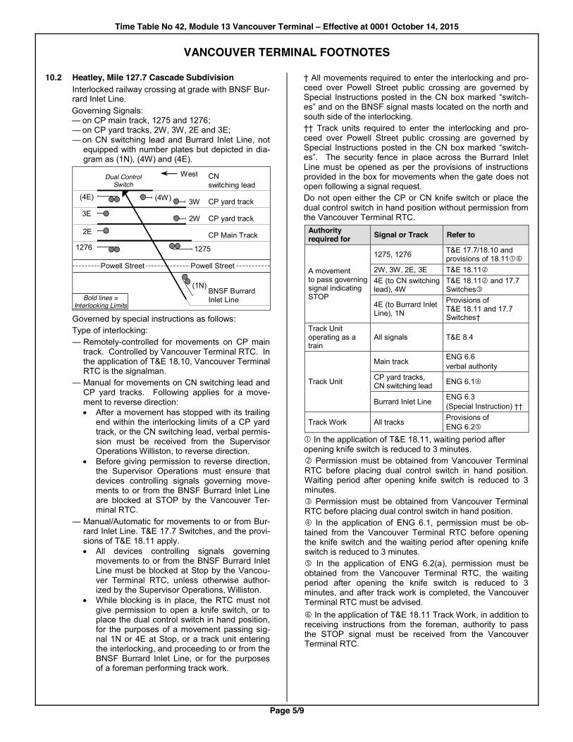
10.2 Heatley, Mile 127.7 Cascade Subdivision Interlocked railway crossing at grade with BNSF Bur-rard Inlet Line. Governing Signals: — on CP main track, 1275 and 1276; — on CP yard tracks, 2W, 3W, 2E and 3E; — on CN switching lead and Burrard Inlet Line, not
equipped with number plates but depicted in dia-gram as (1N), (4W) and (4E).
(4E)
3E
2E
1276
(4W) 3W
2W
1275
CN switching lead
CP yard track
CP yard track
BNSF Burrard Inlet Line
CP Main Track
(1N)
West Dual Control Switch
Bold lines = Interlocking Limits
Powell Street Powell Street
Governed by special instructions as follows: Type of interlocking: — Remotely-controlled for movements on CP main
track. Controlled by Vancouver Terminal RTC. In the application of T&E 18.10, Vancouver Terminal RTC is the signalman.
— Manual for movements on CN switching lead and CP yard tracks. Following applies for a move-ment to reverse direction: x After a movement has stopped with its trailing
end within the interlocking limits of a CP yard track, or the CN switching lead, verbal permis-sion must be received from the Supervisor Operations Williston, to reverse direction.
x Before giving permission to reverse direction, the Supervisor Operations must ensure that devices controlling signals governing move-ments to or from the BNSF Burrard Inlet Line are blocked at STOP by the Vancouver Ter-minal RTC.
— Manual/Automatic for movements to or from Bur-rard Inlet Line. T&E 17.7 Switches, and the provi-sions of T&E 18.11 apply. x All devices controlling signals governing
movements to or from the BNSF Burrard Inlet Line must be blocked at Stop by the Vancou-ver Terminal RTC, unless otherwise author-ized by the Supervisor Operations, Williston.
x While blocking is in place, the RTC must not give permission to open a knife switch, or to place the dual control switch in hand position, for the purposes of a movement passing sig-nal 1N or 4E at Stop, or a track unit entering the interlocking, and proceeding to or from the BNSF Burrard Inlet Line, or for the purposes of a foreman performing track work.
† All movements required to enter the interlocking and pro-ceed over Powell Street public crossing are governed by Special Instructions posted in the CN box marked “switch-es” and on the BNSF signal masts located on the north and south side of the interlocking. †† Track units required to enter the interlocking and pro-ceed over Powell Street public crossing are governed by Special Instructions posted in the CN box marked “switch-es”. The security fence in place across the Burrard Inlet Line must be opened as per the provisions of instructions provided in the box for movements when the gate does not open following a signal request. Do not open either the CP or CN knife switch or place the dual control switch in hand position without permission from the Vancouver Terminal RTC.
Authority required for Signal or Track Refer to
A movement to pass governing signal indicating STOP
1275, 1276 T&E 17.7/18.10 and provisions of 18.11ch
2W, 3W, 2E, 3E T&E 18.11d 4E (to CN switching lead), 4W
T&E 18.11d and 17.7 Switchese
4E (to Burrard Inlet Line), 1N
Provisions of T&E 18.11 and 17.7 Switches†
Track Unit operating as a train
All signals T&E 8.4
Track Unit
Main track ENG 6.6 verbal authority
CP yard tracks, CN switching lead ENG 6.1f
Burrard Inlet Line ENG 6.3 (Special Instruction) ††
Track Work All tracks Provisions of ENG 6.2g
c In the application of T&E 18.11, waiting period after opening knife switch is reduced to 3 minutes. d Permission must be obtained from Vancouver Terminal RTC before placing dual control switch in hand position. Waiting period after opening knife switch is reduced to 3 minutes. e Permission must be obtained from Vancouver Terminal RTC before placing dual control switch in hand position. f In the application of ENG 6.1, permission must be ob-tained from the Vancouver Terminal RTC before opening the knife switch and the waiting period after opening knife switch is reduced to 3 minutes. g In the application of ENG 6.2(a), permission must be obtained from the Vancouver Terminal RTC, the waiting period after opening the knife switch is reduced to 3 minutes, and after track work is completed, the Vancouver Terminal RTC must be advised. h In the application of T&E 18.11 Track Work, in addition to receiving instructions from the foreman, authority to pass the STOP signal must be received from the Vancouver Terminal RTC.
Time Table No 42, Module 13 Vancouver Terminal – Effective at 0001 October 14, 2015
Page 6/9
VANCOUVER TERMINAL FOOTNOTES
11.0 GENERAL FOOTNOTES 11.1 Protection of Dimensional Traffic in Vancouver
Terminal GOI Section 10, item 5.4 applies on: — Cascade Subdivision between D L Zone Signs
miles 106.4 and 129.1; and — on Westminster Subdivision between D L Zone
Sign mile 5.6 and MacAulay. Vancouver Terminal RTC is responsible. Prior to moving on a main track, or non-main track adjacent to a main track, movements handling di-mensional traffic must: — advise the RTC, or receive confirmation from the
Supervisor Operations or Trainmaster, that the RTC has been advised, of the widest classifica-tion being handled; and
— determine from Protection Notices, Supervisor Operations or Trainmaster, if specific restrictions are applicable within the terminal and comply with such restrictions.
11.2 Idling locomotive noise reduction between Pitt River and Onderdonk Eastward movements leaving Pitt River on either track, 7000 feet in length or less, must stop so that the leading end is at least 7100 feet from the east side of Kennedy Road crossing, but not beyond the location of signal 1078S at mile 107.8 unless or until signal 1076N at Onderdonk or 1078S at mile 107.8, indicates a permissive signal indication at Maple Meadows.
11.3 Track between Signals: — 1122N, Port Coquitlam and 1123N, MacAulay; — 1098 and 1099N, Smith, is non-main track and designated NORTH TRACK. Footnote 4.1 speeds and ENG 9.1 apply.
11.4 Special Derail located on west end of track G5, Port Moody.
11.5 Dual control switch point derail located on signalled turnout at the east end north lead, Second Narrows.
11.6 Slide Detector located at mile 124.3, Cascade Sub-division, protected by block signals as indicated in the following chart:
Westward Signals Eastward Signals 1241N and 1241S Second Narrows
1258 and 1258B Renfrew
When necessary to pass a signal displaying Restrict-ing, or when authorized to pass a signal displaying Stop, movements must also be prepared to stop short of obstruction on the track
11.7 Use of tracks M3 and M4 (north and south platform tracks), Vancouver are for the exclusive occupancy of commuter trains from 0600 to 1845 Monday to Friday and at other times when commuter trains are seen to be in service.
11.8 Main track Westminster Subdivision ends at Begin/ End CTC Sign Sapperton.
11.9 Dual control switch point derail located on signalled track, Westminster Subdivision, between crossover switch and Signal 55B, Sapperton. When a signal governing operation over the derail displays a permissive indication, the derail is locked in the non-derailing position. After a movement clears the controlled location, the derail will automat-ically restore to the derailing position. When a track unit is required to move over the de-rail, the foreman must obtain permission from the RTC to operate the derail in the “hand” position. Af-ter the track unit has cleared the switch, the foreman must ensure that the selector lever is restored to the “power” position, locked and the RTC immediately advised.
11.10 Movements from the north leg of BNSF wye at CP Sapperton on BNSF to CP Westminster Subdivision main track or interchange tracks at Sapperton must obtain permission from the CP RTC before leaving BNSF track. Northward movements from CN New Westminster Subdivision to CP Westminster Subdivision via the BNSF Yard must contact the CP RTC before depart-ing CN Fraser River Jct. Movements between mile 5.6 and mile 9.2 Westmin-ster Subdivision are coordinated through the CP Co-quitlam Tower. Crews must obtain permission from the Coquitlam Tower before occupying this track. Movements from BNSF must have this permission prior to entering the CP Westminster Subdivision.
11.11 In the application of T&E 14.8(a), a movement may leave non-main track switches connecting with either Southern Railway of British Columbia (SRY) or CN, between mile 7.0 and mile 9.2 Westminster Subdivi-sion, lined and locked in either position.
Time Table No 42, Module 13 Vancouver Terminal – Effective at 0001 October 14, 2015
Page 7/9
VANCOUVER TERMINAL FOOTNOTES
12.0 SPURS AND OTHER TRACKS 12.1 Vancouver Intermodal Facility
Maximum speed 15 MPH on all yard tracks.
12.2 Coquitlam Yard A. Maximum speed 15 MPH on tracks: — AT01-AT11, and AT13-AT15 — C1-C3 — XT30, XT31, XT41 and XT42 B. T&E 12.2(e) applies on tracks X1-X8, X10,
X20-X22, DS1, DS2, DS3E, DS4, DSF1, DSF2 and DSYS1A
12.3 Maximum speed 10 MPH through turnouts connect-ing tracks G5 and GT Lead.
12.4 Maximum speed 30 MPH on North Platform Track, Vancouver, between Signal 1290 and Circuit End Sign.
12.5 Account less than standard track centres between adjacent tracks, employees must not ride on the side of equipment on tracks NT01-NT17, Vancouver yard.
12.6 Warning devices at the following public crossings may be activated by keying the appropriate code on CP 78 (41-41), but will stop after 30 seconds unless movement detected by constant warning time devic-es:
Mile Spur Crossing Code 0.28 Ioco Murray Street 00281¾
13.00 Marpole Byrne Road 13001¾ 13.86 Marpole Marshland Road 13861¾
0.31
Van Horne Industrial Lead (off mile 0.57 Van Horne Spur)
Van Horne Way 00311
12.7 loco Spur A. Extends northward 3.2 miles; from mile 115.0
Cascade Subdivision to end of track. B. 6 axle units prohibited on, and north of, bridge at
mile 0.5. C. T&E 13.3(c) does not apply at public crossing
mile 0.28, Murray Street. D. In the application of T&E 14.8(a), a movement
may leave non-main track switches on the Ioco Spur lined and locked in either position.
12.8 Van Horne Spur A. Extends southward 1.7 miles; from mile 6.3 Mar-
pole Spur to end of track. B. Maximum speed 5 MPH on all industrial leads. C. 6 axle units prohibited. D. Cars over 268,000 pounds gross weight prohibit-
ed unless authorized by a Protection Notice. E. Mile 0.22
Locally-controlled interlocked drawbridge. Max-imum speed 5 MPH on bridge. When governing signal indicates STOP and there is no indication of bridge being opened, Signalman must be called with four short sounds of the engine whis-tle. If Signalman fails to appear, crew member must determine that swing span is properly closed by observing that rail wedges are in place, and also check for broken rail or obstruction. If all clear, movement may proceed at restricted speed. Normal position of this bridge is open for river traffic. Locomotive sanders must not be used within 20 feet of, or on, swing span. Cars must not be pushed across drawbridge.
F. Public Crossings: — mile 0.31, Van Horne Industrial Lead (off Van
Horne Spur at mile 0.57), Van Horne Way. Automatic warning devices protect three tracks, consisting of two leads at mile 0.31 and an adjacent industrial spur. STOP signs apply to southward movements on both leads and to northward movements on the lead to the left (west side).
— mile 0.69, Great Canadian Way. STOP sign applies to northward movements and T&E 13.3(e) applies to all movements.
— T&E 13.3(e) applies at the following public crossings: mile 0.91, 1.11, 1.18 and 1.19.
— mile 1.7, Cambie Road. Do not exceed 5 MPH until crossing is fully occupied.
— mile 1.36, Capstan Way. STOP signs located 50 feet in advance of public crossing.

Time Table No 42, Module 13 Vancouver Terminal – Effective at 0001 October 14, 2015
Page 8/9
VANCOUVER TERMINAL FOOTNOTES
12.9 Marpole Spur A. Extends westward 16.0 miles; from New West-
minster to end of track. Mile posts are numbered from west to east.
B. Maximum speed 5 MPH on all industrial leads. C. 6 axle units prohibited between mile 0.0 and mile
14.2. D. Movements west of Hudson Street, mile 6.2, are,
prohibited, except as authorized by the General Manager Engineering Services or designate.
E. All movements between mile 13.5 and New Westminster Yard, mile 16.0 must be authorized by Southern Railway of BC RTC. This may be done directly by telephone at (604) 521-4821, or relayed through the RTC.
F. Public Crossings — mile 15.1, 20th Street.
T&E 13.5 applies. — mile 13.9, Marshland Avenue.
Equipped with pushbuttons. Equipment must not be left standing on the ABC Salvage Lead between the switch and the crossing.
— mile 6.16, Hudson Street. STOP signs apply to westward movements on Marpole Spur and all movements on Marpole Industrial Lead (track O5 Borden). Automatic warning devices will be activated 15 seconds after occupying circuit (traffic signals at Hud-son Street and Marine Drive are interconnect-ed with the crossing circuits). Equipment must not be left standing between the Circuit End Sign and the crossing.
— T&E 13.5 applies at public crossings between and including mile 6.16, Hudson Street and mile 2.1, King Edward Avenue.
— mile 1.25, Broadway Avenue. Crossing protected by a bell and roadway traf-fic signals only. Indicator lights (similar to dwarf signals), capable of displaying red or green, are located on both sides of crossing. When indicator light displays green, move-ments may proceed over crossing. When indi-cator light displays red, a crew member must operate pushbutton, located in box on both sides of crossing, then not obstruct crossing until indicator light displays green. Should in-dicator light continue to display red, T&E 13.5 applies. Indicator light will display green when a move-ment has occupied the approach circuit for 10 seconds. If the movement occupies the track circuit for longer than two minutes, the indica-tor light will change to display red.
— mile 0.28, First Avenue. STOP sign applies to eastward movements on Marpole and Molson Spurs. Sign is located between these two tracks 105 feet from cross-ing.
— T&E 13.3(e) applies at public crossings be-tween mile 2.1 and end of track mile 0.0.
G. Restricted clearance between Marpole Spur and hydro poles located on both sides of Marpole Spur between mile 0.47 and mile 15.13 not marked by restricted clearance signs
H. In the application of T&E 14.8(a), a movement may leave non-main track switches connecting with either Southern Railway of British Columbia (SRY) or CN, between mile 16.0 and mile 15.0, lined and locked in either position.
I. At Sixteenth Street yard, mile 15.4, equipment must not be left standing closer than 75 feet from the travelled portion of Sixteenth Street or Fourth Avenue.
J. In the application of GOI Section 3 Item 12.1, de-scending grades of 2% or greater are as follows: Direction Grade 2% > Test Location Westward Mile 3.63 to Mile 0.28 Before passing
over 41st Ave. Mile 3.63
Eastward Mile 3.63 to Marpole
12.10 Coquitlam Diesel Shop Tracks A. Prior to entering the Diesel Shop track, all crews
must contact the Area 1 Planner by radio on Digi-tal Diesel A1 to receive permission to enter the area and receive yarding instructions. In addition, freight crews must contact the Area 1 Planner on Digital Diesel A1 to receive any other shop track information or instructions regarding their locomotives. If unable to contact the Area 1 Planner crews should contact the Coquitlam Tower for instruc-tions.
B. Maximum speed 5 MPH, except for departing lo-comotives once clear of Diesel Shop lead switch.
Time Table No 42, Module 13 Vancouver Terminal – Effective at 0001 October 14, 2015
Page 9/9
VANCOUVER TERMINAL FOOTNOTES
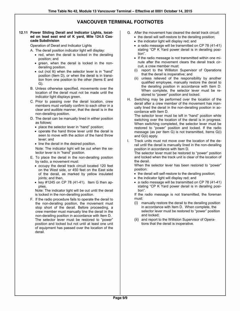
12.11 Power Sliding Derail and Indicator Lights, locat-ed on lead east end of K yard, Mile 124.5 Cas-cade Subdivision Operation of Derail and Indicator Lights A. The derail position indicator light will display:
x red, when the derail is locked in the derailing position; and
x green, when the derail is locked in the non-derailing position.
x out (not lit) when the selector lever is in “hand” position (Item D), or when the derail is in transi-tion from one position to the other (Items E and G).
B. Unless otherwise specified, movements over the location of the derail must not be made until the indicator light displays green.
C. Prior to passing over the derail location, crew members must verbally confirm to each other in a clear and audible manner, that the derail is in the non-derailing position.
D. The derail can be manually lined in either position as follows: x place the selector lever in “hand” position;; x operate the hand throw lever until the derail is
seen to move with the action of the hand throw lever; and
x line the derail in the desired position. Note: The indicator light will be out when the se-
lector lever is in “hand” position. E. To place the derail in the non-derailing position
by radio, a movement must: x occupy the derail track circuit located 120 feet
on the West side, or 450 feet on the East side of the derail, as marked by yellow insulated joints; and then,
x key #1245 on CP 78 (41-41). Item G then ap-plies.
Note: The indicator light will be out until the derail is locked in the non-derailing position.
F. If the radio procedure fails to operate the derail to the non-derailing position, the movement must stop short of the derail. Before proceeding, a crew member must manually line the derail in the non-derailing position in accordance with Item D. The selector lever must be restored to “power” position and locked but not until at least one unit of equipment has passed over the location of the derail.
G. After the movement has cleared the derail track circuit: x the derail will self-restore to the derailing position; x the indicator light will display red; and x a radio message will be transmitted on CP 78 (41-41)
stating “CP K Yard power derail is in derailing posi-tion”.
x If the radio message is not transmitted within one mi-nute after the movement clears the derail track cir-cuit, a crew member must:
(i) report to the Williston Supervisor of Operations that the derail is inoperative; and
(ii) unless relieved of the responsibility by another qualified employee, manually restore the derail to the derailing position in accordance with Item D. When complete, the selector lever must be re-stored to “power” position and locked.
H. Switching may be performed over the location of the derail after a crew member of the movement has man-ually lined the derail in the non-derailing position in ac-cordance with Item D. The selector lever must be left in “hand” position while switching over the location of the derail is in progress. When switching completed, the selector lever must be restored to “power” position and locked. If the radio message (as per Item G) is not transmitted, Items G(i) and G(ii) apply.
I. Track units must not move over the location of the de-rail until the derail is manually lined in the non-derailing position in accordance with Item D. The selector lever must be restored to “power” position and locked when the track unit is clear of the location of the derail. When the selector lever has been restored to “power” position: x the derail will self-restore to the derailing position; x the indicator light will display red; and x a radio message will be transmitted on CP 78 (41-41)
stating “CP K Yard power derail is in derailing posi-tion”.
If the radio message is not transmitted, the foreman must: (i) manually restore the derail to the derailing position
in accordance with Item D. When complete, the selector lever must be restored to “power” position and locked;
(ii) and report to the Williston Supervisor of Opera-tions that the derail is inoperative.

Pacific Division Time Table No 42, Module 6 Mission Subdivision – Effective at 0001 October 14, 2015
Page 1/3
Tra
in S
tand
by
Cha
nnel
Poi
nt to
Tra
in
Tow
er C
ode
RT
C C
all-i
n C
hann
el
and
RT
C C
all-i
n C
ode
RT
C A
utho
ritie
s C
hann
el
Emer
genc
y Ca
ll-in
Cod
e
Util
ity C
hann
el a
nd
RT
C C
all-i
n C
ode
Util
ity T
ower
Cod
e
Mai
nten
ance
of W
ay
Cha
nnel
Mile
s fr
om M
issi
on J
ct
NORT
HWAR
D MISSION SUBDIVISION (Subdivision No 6004)
TrAM Area 1 north of Matsqui Jct, Area 4 south of Matsqui Jct SO
UTHW
ARD
Mai
n T
rack
(s)
Met
hod
of C
ontro
l
TG
BO
/ D
OB
Lim
its
Sid
ing
Cap
acity
in F
eet
Sig
nalle
d S
idin
g
Sta
tion
Num
ber
STATIONS
CP 1
91-91
063
CP 3
21-91
¾61#
CP 5
81-81
911
CP 12
15-49
¾61#
163
CP 11
49-49
10.1
HUNTINGDON International Boundary and
connection with BNSF Railway NMT Yard 9710
1.6 9659
8.5 VEDDER
1
OC
S
DO
B
6.7
1.8 ABBOTSFORD 9708
4.0 2.7
Non-Interlocked Railway Crossing
1.5
2.5 Interlocked Railway Crossing
1.4 0.1
MATSQUI JCT Connection to CN
9704
C
TC
1.0 0.4
RIVERSIDE Jct Page Sub
9709
0.8
0.2 Interlocked Drawbridge
0.5
0.3 STO:LO 9739
0.0
0.5 MISSION JCT
Jct Cascade Sub Y Yard 9675
MISSION SUBDIVISION FOOTNOTES
0.0 RADIO
0.1 Zone Code (Z) is 6.
0.2 To call Engineering Service Reliability, dial ¾61106# on CP 12 (15-49).
0.3 The use of CP 16 (77-77) is prohibited.
2.0 EQUIPMENT RESTRICTIONS 2.1 Diesel units
— 6 axle units must not exceed 20 MPH. — 6 axle units prohibited on storage track Ab-botsford.
2.2 Cars — over 268,000 pounds not exceeding 286,000 pounds gross weight, 42 feet or longer, 10 MPH on bridges miles 1.8, 2.1 and 8.4.
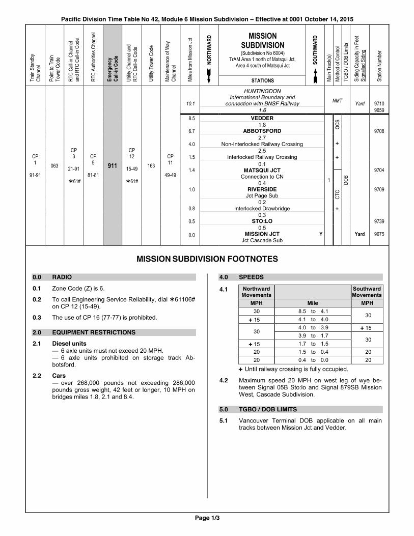
4.0 SPEEDS
4.1 Northward Movements Southward
Movements MPH Mile MPH 30 8.5 to 4.1
30 + 15 4.1 to 4.0
30 4.0 to 3.9 + 15
3.9 to 1.7 30
+ 15 1.7 to 1.5 20 1.5 to 0.4 20 20 0.4 to 0.0 20
+ Until railway crossing is fully occupied.
4.2 Maximum speed 20 MPH on west leg of wye be-tween Signal 05B Sto:lo and Signal 879SB Mission West, Cascade Subdivision.
5.0 TGBO / DOB LIMITS 5.1 Vancouver Terminal DOB applicable on all main
tracks between Mission Jct and Vedder.
+
+
+
Pacific Division Time Table No 42, Module 6 Mission Subdivision – Effective at 0001 October 14, 2015
Page 2/3
MISSION SUBDIVISION FOOTNOTES
6.0 CENTRALIZED TRAFFIC CONTROL 6.1 CTC Rules apply between Mission Jct and Matsqui
Jct.
6.2 West leg of wye between Signal 05B Sto:lo and Sig-nal 879SB Mission West, Cascade Subdivision, is a signalled track and CTC Rules apply.
7.0 OCCUPANCY CONTROL SYSTEM 7.1 OCS Rules apply between Begin/End CTC Sign
Matsqui Jct and Station Name Sign Vedder.
9.0 PUBLIC CROSSINGS AT GRADE 9.1 Mile 3.99, Clayburn Road
T&E 13.5 applies.
9.2 Warning devices at the following public crossings may be activated by keying the appropriate code on CP 1 (91-91), but will stop after 30 seconds unless move-ment detected by constant warning time devices:
Mile Crossing Code 5.68 McClure Road 05681 6.51 George Ferguson Way 06511¾ 6.59 Essendene Ave 06591¾ 7.64 Marshall Road 07641 9.12 Vye Road 009121¾
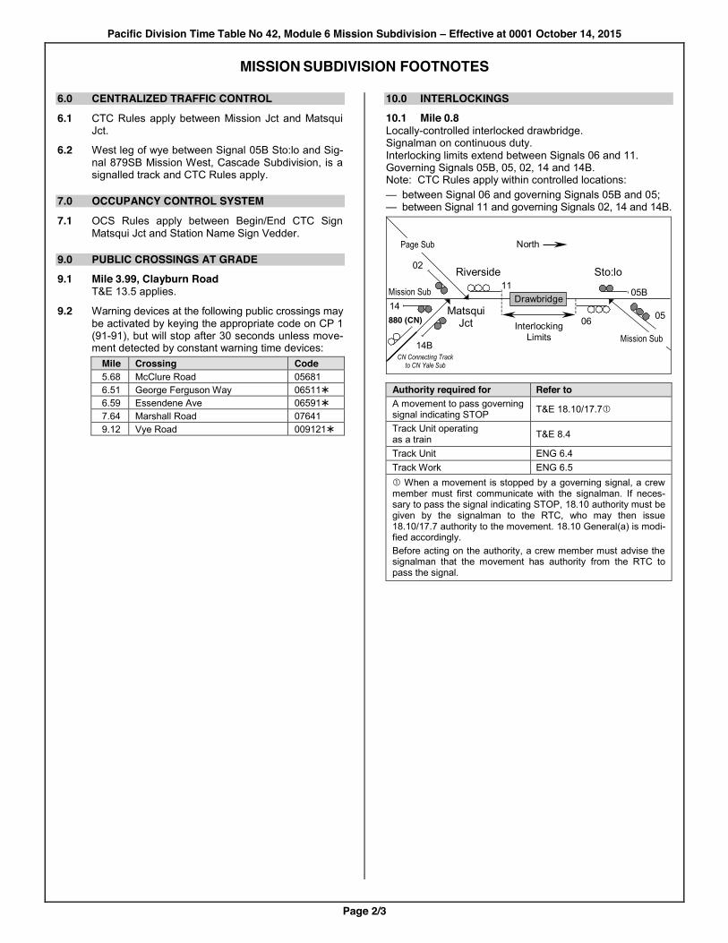
10.0 INTERLOCKINGS 10.1 Mile 0.8 Locally-controlled interlocked drawbridge. Signalman on continuous duty. Interlocking limits extend between Signals 06 and 11. Governing Signals 05B, 05, 02, 14 and 14B. Note: CTC Rules apply within controlled locations: — between Signal 06 and governing Signals 05B and 05; — between Signal 11 and governing Signals 02, 14 and 14B.
14
North
05B
02
11 Drawbridge
Interlocking Limits
06 05 Matsqui Jct
Riverside
Page Sub
Mission Sub
Mission Sub
880 (CN)
14B
Sto:lo
CN Connecting Track to CN Yale Sub
Authority required for Refer to A movement to pass governing signal indicating STOP T&E 18.10/17.7c
Track Unit operating as a train T&E 8.4
Track Unit ENG 6.4 Track Work ENG 6.5 c When a movement is stopped by a governing signal, a crew member must first communicate with the signalman. If neces-sary to pass the signal indicating STOP, 18.10 authority must be given by the signalman to the RTC, who may then issue 18.10/17.7 authority to the movement. 18.10 General(a) is modi-fied accordingly. Before acting on the authority, a crew member must advise the signalman that the movement has authority from the RTC to pass the signal.

Pacific Division Time Table No 42, Module 6 Mission Subdivision – Effective at 0001 October 14, 2015
Page 3/3
MISSION SUBDIVISION FOOTNOTES
10.2 Mile 1.5 Automatic interlocked railway crossing at grade with CN Yale Subdivision.
Authority required for Refer to A movement to pass governing signal indicating STOP T&E 18.11
Track Unit operating as a train T&E 8.4
Track Unit ENG 6.1 Track Work ENG 6.2
In the application of T&E 18.11 and ENG 6.1, a crew member, or foreman as applicable, must contact CN RTC before opening the switch and the waiting time is increased to 8 minutes. To contact CN Yale Subdivision RTC select CP 95 (73-73), touch code ¾1#, and remain on this chan-nel to converse; or by telephone, call 1-866-366-2347, then, after receiving a second dial tone, dial 5083 to be placed in queue. If the above does not establish contact, then by telephone, dial (780) 472-3738.
10.3 Mile 4.0 Non-interlocked railway crossing at grade with Southern Railway of BC Fraser Valley Subdivision. STOP signs on CP track are located 87 feet north, and 108 feet south, of crossing.
Authority required for Refer to A movement to pass governing STOP sign T&E 18.5
A Track Unit to operate beyond the governing STOP sign
ENG 6.8
Track Work c Provisions of ENG 5.3 d c Before starting any track work, the RTC of both rail-ways must be advised. SRY RTC may be contacted at (604) 521-4821. d In the application of 5.3(b), red signals must be placed on both railways in each direction from the work-ing point. On CP track, red signals must be placed be-tween the rails, at the location of the STOP signs.
11.0 GENERAL FOOTNOTES 11.1 Station Name Sign for Sto:lo for southward move-
ments located at Signal No 004 Mission Jct.
11.2 Main track ends at Station Name Sign Vedder, mile 8.5.
11.3 In the application of T&E 14.8(a), a movement may leave non-main track switches in Huntingdon yard lined and locked in either position.
12.0 SPURS AND OTHER TRACKS 12.1 Movements required to stop on the west leg of the
wye, Mission Jct, must not block the private road crossing to the Engineering Services maintenance facility at Sto:lo. Southward movements affected must stop at least 75 feet in advance of the crossing.
12.2 Huntingdon A. Crews must advise the SRY yard office on
channel 18-18 before occupying, or setting off equipment in tracks CP(SRY) 3 or CP(SRY) 4, and when such tracks are no longer required.
B. Maximum speed 5 MPH while passing struc-tures or buildings in track 6.
C. Restricted overhead clearances not marked with restricted clearance signs, located on tracks 6, 10 and 11.

Pacific Division Time Table No 42, Module 9 Page Subdivision – Effective at 0001 October 14, 2015
Page 1/2
Train
Stan
dby
Chan
nel
Point
to T
rain
To
wer C
ode
RTC
Call-i
n Cha
nnel
and R
TC C
all-in
Cod
e
RTC
Autho
rities
Cha
nnel
Emer
genc
y Ca
ll-in
Cod
e
Utilit
y Cha
nnel
and
RTC
Call-i
n Cod
e
Utilit
y Tow
er C
ode
Maint
enan
ce of
Way
Ch
anne
l
Miles
from
Rive
rside
WES
TWAR
D PAGE SUBDIVISION (Subdivision No 6005)
TrAM Area 1 EAST
WAR
D
Main
Trac
k(s)
Metho
d of C
ontro
l TG
BO / D
OB Li
mits
Sidin
g Cap
acity
in F
eet
Sign
alled
Sidi
ng
Stati
on N
umbe
r
STATIONS
CP 1
91-91 063
CP 3
21-91 ¾61#
CP 5
81-81 911
CP 12
15-49 ¾61#
163 CP 11
49-49
0.0 RIVERSIDE Jct Mission Sub
1 CTC
DOB
9709
2.0 2.0
PAGE Jct CN
9692
Movements between Page and Livingstone are governed by CN Time Table, Rules and Regulations.
CP 77
39-39
064
CP 3
21-91
¾61#
CP 5
81-81 911
CP 12
15-49
¾61#
164 CP 11
49-49
16.4 14.4
LIVINGSTONE Jct CN and
Southern Railway of BC (SRY)
1 CTC
DOB
9725
18.9 2.5 MILNER
9735
21.0 2.1 LANGLEY
9731
23.6
2.6 VIEW
Jct Southern Railway of BC (SRY)
24.0 0.4
PRATT Jct BCR
9640
9730
Movements between Pratt and Roberts Bank are governed by BCR Time Table, Rules and Regulations.
44.2 20.2
ROBERTS BANK B
9707
PAGE SUBDIVISION FOOTNOTES
0.0 RADIO 0.1 Zone Code (Z) is 6.
0.2 To call Engineering Service Reliability, dial ¾61106# on CP 12 (15-49).
0.3 The use of CP 16 (77-77) is prohibited.
0.4 While operating between Riverside and Page, crews on movements must monitor CP 101 (87-87). This channel must be used in the application of T&E 5.2(a).
0.5 When necessary to contact CN RTC, select CP 95 (73-73), key ¾1# (or in case of emergency ¾0#), and remain on this channel to converse with CN RTC.
0.6 When necessary to contact BCR RTC, select CP 77 (39-39), key ¾1# (or in case of emergency ¾0#), and remain on this channel to converse with BCR RTC.
3.0 DANGEROUS COMMODITIES 3.1 All movements operating between Livingstone and
Pratt handling one or more full carloads, container-loads or trailerloads of SPECIAL dangerous com-modities must not travel more than 20 miles without receiving an inspection as per GOI Section 5 item 1.1 or from an operating hot box and dragging equip-ment detector. This distance is to include miles trav-elled on connecting railways at Livingstone or Pratt.
4.0 SPEEDS
4.1 Westward Movements Eastward
Movements MPH Mile MPH 30 0.0 to 2.0 30 35 16.4 to 24.0 35
4.2 Maximum speed 30 MPH on that portion of Pratt siding between Signal 236B, View and Station Name Sign Pratt, mile 24.0.
Pacific Division Time Table No 42, Module 9 Page Subdivision – Effective at 0001 October 14, 2015
Page 2/2
PAGE SUBDIVISION FOOTNOTES
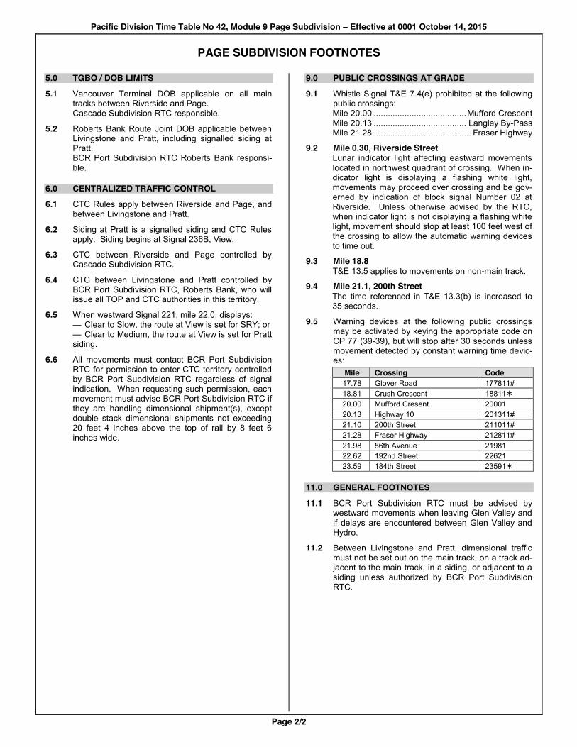
5.0 TGBO / DOB LIMITS 5.1 Vancouver Terminal DOB applicable on all main
tracks between Riverside and Page. Cascade Subdivision RTC responsible.
5.2 Roberts Bank Route Joint DOB applicable between Livingstone and Pratt, including signalled siding at Pratt. BCR Port Subdivision RTC Roberts Bank responsi-ble.
6.0 CENTRALIZED TRAFFIC CONTROL 6.1 CTC Rules apply between Riverside and Page, and
between Livingstone and Pratt.
6.2 Siding at Pratt is a signalled siding and CTC Rules apply. Siding begins at Signal 236B, View.
6.3 CTC between Riverside and Page controlled by Cascade Subdivision RTC.
6.4 CTC between Livingstone and Pratt controlled by BCR Port Subdivision RTC, Roberts Bank, who will issue all TOP and CTC authorities in this territory.
6.5 When westward Signal 221, mile 22.0, displays: — Clear to Slow, the route at View is set for SRY; or — Clear to Medium, the route at View is set for Pratt siding.
6.6 All movements must contact BCR Port Subdivision RTC for permission to enter CTC territory controlled by BCR Port Subdivision RTC regardless of signal indication. When requesting such permission, each movement must advise BCR Port Subdivision RTC if they are handling dimensional shipment(s), except double stack dimensional shipments not exceeding 20 feet 4 inches above the top of rail by 8 feet 6 inches wide.
9.0 PUBLIC CROSSINGS AT GRADE 9.1 Whistle Signal T&E 7.4(e) prohibited at the following
public crossings: Mile 20.00 ....................................... Mufford Crescent Mile 20.13 ....................................... Langley By-Pass Mile 21.28 ......................................... Fraser Highway
9.2 Mile 0.30, Riverside Street Lunar indicator light affecting eastward movements located in northwest quadrant of crossing. When in-dicator light is displaying a flashing white light, movements may proceed over crossing and be gov-erned by indication of block signal Number 02 at Riverside. Unless otherwise advised by the RTC, when indicator light is not displaying a flashing white light, movement should stop at least 100 feet west of the crossing to allow the automatic warning devices to time out.
9.3 Mile 18.8 T&E 13.5 applies to movements on non-main track.
9.4 Mile 21.1, 200th Street The time referenced in T&E 13.3(b) is increased to 35 seconds.
9.5 Warning devices at the following public crossings may be activated by keying the appropriate code on CP 77 (39-39), but will stop after 30 seconds unless movement detected by constant warning time devic-es:
Mile Crossing Code 17.78 Glover Road 177811# 18.81 Crush Crescent 18811¾ 20.00 Mufford Cresent 20001 20.13 Highway 10 201311# 21.10 200th Street 211011# 21.28 Fraser Highway 212811# 21.98 56th Avenue 21981 22.62 192nd Street 22621 23.59 184th Street 23591¾
11.0 GENERAL FOOTNOTES 11.1 BCR Port Subdivision RTC must be advised by
westward movements when leaving Glen Valley and if delays are encountered between Glen Valley and Hydro.
11.2 Between Livingstone and Pratt, dimensional traffic must not be set out on the main track, on a track ad-jacent to the main track, in a siding, or adjacent to a siding unless authorized by BCR Port Subdivision RTC.
Pacific Division Time Table No 42, Module 11 Thompson Subdivision – Effective at 0001 October 14, 2015
Page 1/3
Trai
n St
andb
y
Chan
nel
Point
to T
rain
Towe
r Cod
e
RTC
Call-
in C
hann
el an
d RT
C Ca
ll-in
Cod
e
Emer
genc
y Ca
ll-in
Cod
e
Utilit
y Ch
anne
l and
RT
C Ca
ll-in
Cod
e
Utilit
y To
wer C
ode
Main
tena
nce
of W
ay
Chan
nel
Mile
s fro
m K
amloo
ps
WES
TWAR
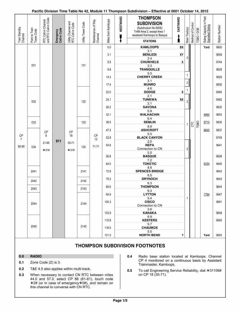
D THOMPSON SUBDIVISION (Subdivision No 6006)
TrAM Area 2, except Area 1 westward Kamloops to Basque
EAST
WAR
D
Main
Tra
ck(s
)
Met
hod
of C
ontro
l
TGBO
/ DO
B
Sidi
ng C
apac
ity in
Fee
t Si
gnal
led S
iding
Stat
ion N
umbe
r
STATIONS
CP 7
95-95
031
CP 8
21-95
¾31#
911
CP 18
35-71
¾31#
131
CP 13
71-71
0.0 KAMLOOPS BX
2
Yard 9600
3.1 3.1 BENLEDI XY 9639
5.5 2.4 CHUWHELS X 9744
8.8 3.3 TRANQUILLE 9628
14.3 5.5 CHERRY CREEK 1 9629
17.4 3.1 MUNRO 2 9630
032 132
22.0 4.6 DODGE S 1
9494
24.1 2.1 TUNKWA SX
2 9492
26.2 2.1 SAVONA 9632
32.1 5.9 WALHACHIN
1 CTC
TGBO
9460 9633
033 133 38.5 6.4 SEMLIN 9710 9635
47.3 8.8
ASHCROFT 8645 9637
034 134
52.8 5.5 BLACK CANYON 9745
54.8 2.0
NEPA Connection to CN
2
9641
56.8 2.0 BASQUE 9638
64.0 7.2 TOKETIC
1
9230 9640
2041 2141 72.8 8.8 SPENCES BRIDGE 9642
79.3 6.5 DRYNOCH 9643 2042 2142
85.6 6.3 THOMPSON 9644 2043 2143
94.9 9.3 LYTTON 7784 9647
2044 2144 100.3 5.4
CISCO Connection to CN
9651
103.9 3.6 KANAKA 9649
2045 2145
110.8 6.9 KEEFERS 9650
116.5 5.7 CHAUMOX
121.5
5.0 NORTH BEND
Y
Yard
9655
THOMPSON SUBDIVISION FOOTNOTES
0.0 RADIO 0.1 Zone Code (Z) is 3.
0.2 T&E 4.5 also applies within multi-track.
0.3 When necessary to contact CN RTC between miles 44.0 and 57.0, select CP 88 (61-61), touch code ¾2# (or in case of emergency¾0#), and remain on this channel to converse with CN RTC.
0.4 Radio base station located at Kamloops. Channel CP 4 monitored on a continuous basis by Assistant Trainmaster, Kamloops.
0.5 To call Engineering Service Reliability, dial ¾31106# on CP 18 (35-71).
Pacific Division Time Table No 42, Module 11 Thompson Subdivision – Effective at 0001 October 14, 2015
Page 2/3
THOMPSON SUBDIVISION FOOTNOTES
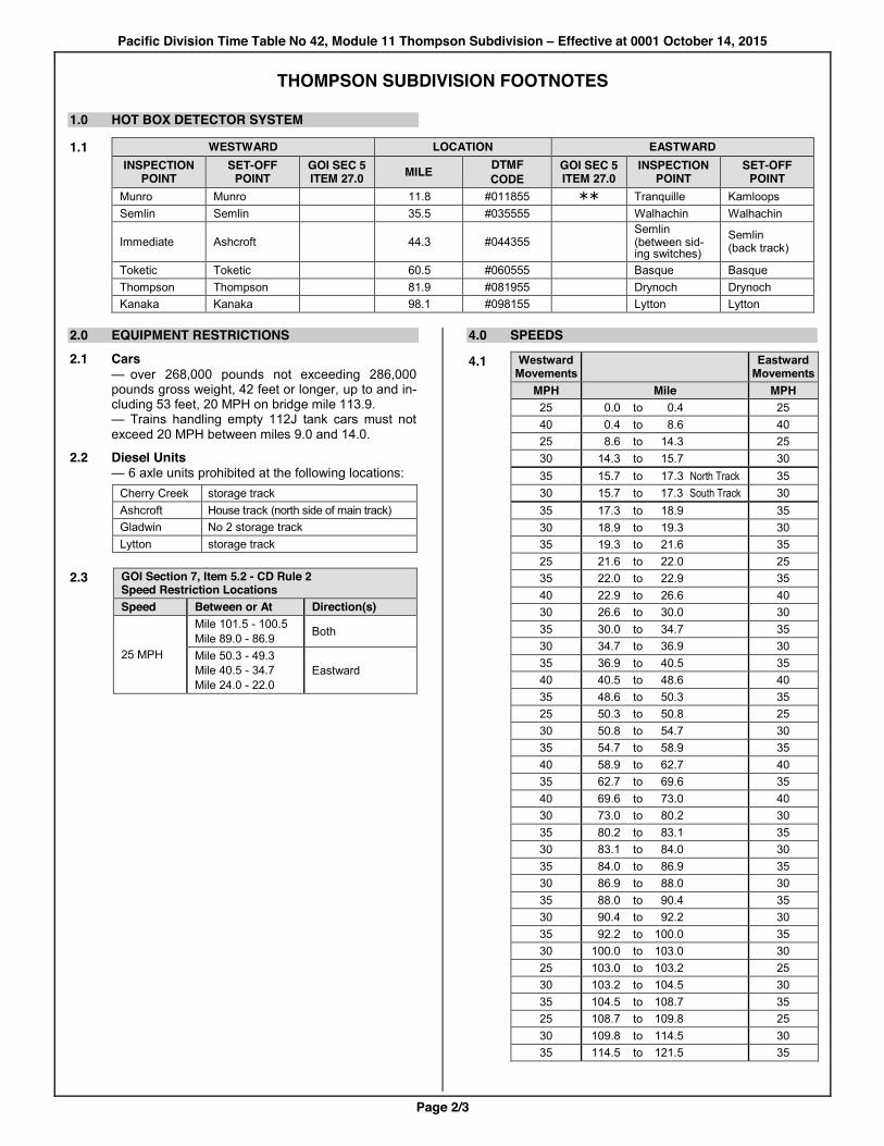
1.0 HOT BOX DETECTOR SYSTEM
1.1 WESTWARD LOCATION EASTWARD
INSPECTION
POINT SET-OFF
POINT GOI SEC 5 ITEM 27.0 MILE DTMF
CODE GOI SEC 5 ITEM 27.0
INSPECTION POINT
SET-OFF POINT
Munro Munro 11.8 #011855 ¾¾ Tranquille Kamloops Semlin Semlin 35.5 #035555 Walhachin Walhachin
Immediate Ashcroft 44.3 #044355 Semlin (between sid-ing switches)
Semlin (back track)
Toketic Toketic 60.5 #060555 Basque Basque Thompson Thompson 81.9 #081955 Drynoch Drynoch Kanaka Kanaka 98.1 #098155 Lytton Lytton
2.0 EQUIPMENT RESTRICTIONS 2.1 Cars
— over 268,000 pounds not exceeding 286,000 pounds gross weight, 42 feet or longer, up to and in-cluding 53 feet, 20 MPH on bridge mile 113.9. — Trains handling empty 112J tank cars must not exceed 20 MPH between miles 9.0 and 14.0.
2.2 Diesel Units — 6 axle units prohibited at the following locations:
Cherry Creek storage track Ashcroft House track (north side of main track) Gladwin No 2 storage track Lytton storage track
2.3 GOI Section 7, Item 5.2 - CD Rule 2
Speed Restriction Locations Speed Between or At Direction(s)
25 MPH
Mile 101.5 - 100.5 Mile 89.0 - 86.9 Both
Mile 50.3 - 49.3 Mile 40.5 - 34.7 Mile 24.0 - 22.0
Eastward
4.0 SPEEDS
4.1 Westward Movements Eastward
Movements MPH Mile MPH 25 0.0 to 0.4 25 40 0.4 to 8.6 40 25 8.6 to 14.3 25 30 14.3 to 15.7 30 35 15.7 to 17.3 North Track 35 30 15.7 to 17.3 South Track 30 35 17.3 to 18.9 35 30 18.9 to 19.3 30 35 19.3 to 21.6 35 25 21.6 to 22.0 25 35 22.0 to 22.9 35 40 22.9 to 26.6 40 30 26.6 to 30.0 30 35 30.0 to 34.7 35 30 34.7 to 36.9 30 35 36.9 to 40.5 35 40 40.5 to 48.6 40 35 48.6 to 50.3 35 25 50.3 to 50.8 25 30 50.8 to 54.7 30 35 54.7 to 58.9 35 40 58.9 to 62.7 40 35 62.7 to 69.6 35 40 69.6 to 73.0 40 30 73.0 to 80.2 30 35 80.2 to 83.1 35 30 83.1 to 84.0 30 35 84.0 to 86.9 35 30 86.9 to 88.0 30 35 88.0 to 90.4 35 30 90.4 to 92.2 30 35 92.2 to 100.0 35 30 100.0 to 103.0 30 25 103.0 to 103.2 25 30 103.2 to 104.5 30 35 104.5 to 108.7 35 25 108.7 to 109.8 25 30 109.8 to 114.5 30 35 114.5 to 121.5 35

Pacific Division Time Table No 42, Module 11 Thompson Subdivision – Effective at 0001 October 14, 2015
Page 3/3
THOMPSON SUBDIVISION FOOTNOTES
4.2 Maximum speed 30 MPH on sidings.
4.3 Maximum speed 25 MPH through turnouts at cross-over switches at Benledi.
4.4 Speed Restrictions, Extreme Temperatures In the application of GOI Section 5, item 29.0, if the ambient temperature in degrees Celsius:
Drops to or below Between Miles Tracks MPH
- 35 Entire Subdivision All Main 35 Rises to or
above Between Miles Tracks MPH
36 Entire Subdivision All Main 5 less than speed in 4.1
5.0 TGBO / DOB LIMITS
5.1 TGBO applicable on all main tracks and signalled sidings between Kamloops and North Bend.
6.0 CENTRALIZED TRAFFIC CONTROL 6.1 CTC Rules apply between Kamloops and North
Bend.
6.2 All sidings are signalled sidings and CTC Rules apply.
9.0 PUBLIC CROSSINGS AT GRADE 9.1 Whistle signal T&E 7.4(e) prohibited at the following
public crossings: Mile 0.10 .................................................. 3rd Avenue Mile 0.21 ................................................. 2nd Avenue Mile 47.06 ................................ Highland Valley Road Mile 47.79 ......................................... Railway Avenue
9.2 Warning devices at the following public crossings may be activated by keying the appropriate code on CP 7 (95-95), but will stop after 60 seconds unless motion detected by constant warning time devices:
Location Crossing Code Mile 0.10 3rd Avenue 001 Mile 0.21 2nd Avenue 002 Mile 2.07 Mission Flats Road 02071¾ Mile 71.83 Highway 8 71831¾
9.3 Mile 2.07, Mission Flats Road When required to stop clear of crossing, movements must stop at least 150 feet from crossing.
9.4 Mile 56.0, Drinkwater Road (Private Crossing) Movements must be cut when crossing will be blocked in excess of 30 minutes between 0900 and 1800. Crossing must be left clear until movement is ready to proceed.
11.0 GENERAL FOOTNOTES
11.1 Restricted clearances not marked by restricted clearance signs located at: — signal 01N between North track and west end of track 1, Kamloops; — North Bend between Main track and passing track, mile 121.0 to mile 0.4 Cascade Subdivision.
11.2 Dual control switch point derails located on signalled turnouts: — at the west end of track 1, Kamloops yard; — within controlled location North Bend East, at mile 120.3.
11.3 Special Derails located on: — South track at mile 22.05, Dodge; and — South track at mile 24.05, Tunkwa.
11.4 Slide Detectors are located and protected by block signals as indicated in the following chart:
Detector Location
Westward Signal(s)
Eastward Signal(s)
Miles 83.2, 84.0 831 mile 83.1
848 Thompson East
Mile 87.8 861, 861D Thompson West
880 mile 88.0
Mile 100.1 993 mile 99.3
1016 mile 101.6
Mile 102.6 1017 mile 101.7
1032 Kanaka East
When necessary to pass a signal displaying Restrict-ing, or when authorized to pass a signal displaying Stop, movements must also be prepared to stop short of obstruction on the track
11.5 Westward movements must contact Cascade Sub-division RTC at Chaumox for routing instructions through North Bend. China Bar radio tower will be used for this purpose.
12.0 SPURS AND OTHER TRACKS 12.1 Kamloops Yard
A. Maximum speed 15 MPH on track 1 and on yard lead between Kamloops East and mile 127.9 Shuswap Subdivision.
B. In the application of T&E 14.8(a), a movement may leave non-main track switches in Kamloops yard, except crossover switches, lined and locked in either position.
12.2 Benledi Wye Maximum speed 5 MPH and only single units may be turned.
12.3 Ashcroft Yard In the application of T&E 14.8(a), a movement may leave non-main track switches in the Ashcroft yard lined and locked in either position.
12.4 Connecting track to CN Ashcroft Subdivision at Cis-co, connected to CP at east end.
12.5 North Bend Yard A. Maximum speed 15 MPH on track 1, lead and
passing tracks. B. Maximum speed 5 MPH on wye and only single
units may be turned. C. In the application of T&E 14.8(a), a movement
may leave non-main track switches in North Bend yard lined and locked in either position.
12.6 Station Numbers: Mile 90.1 (Gladwin) ............................................ 9645
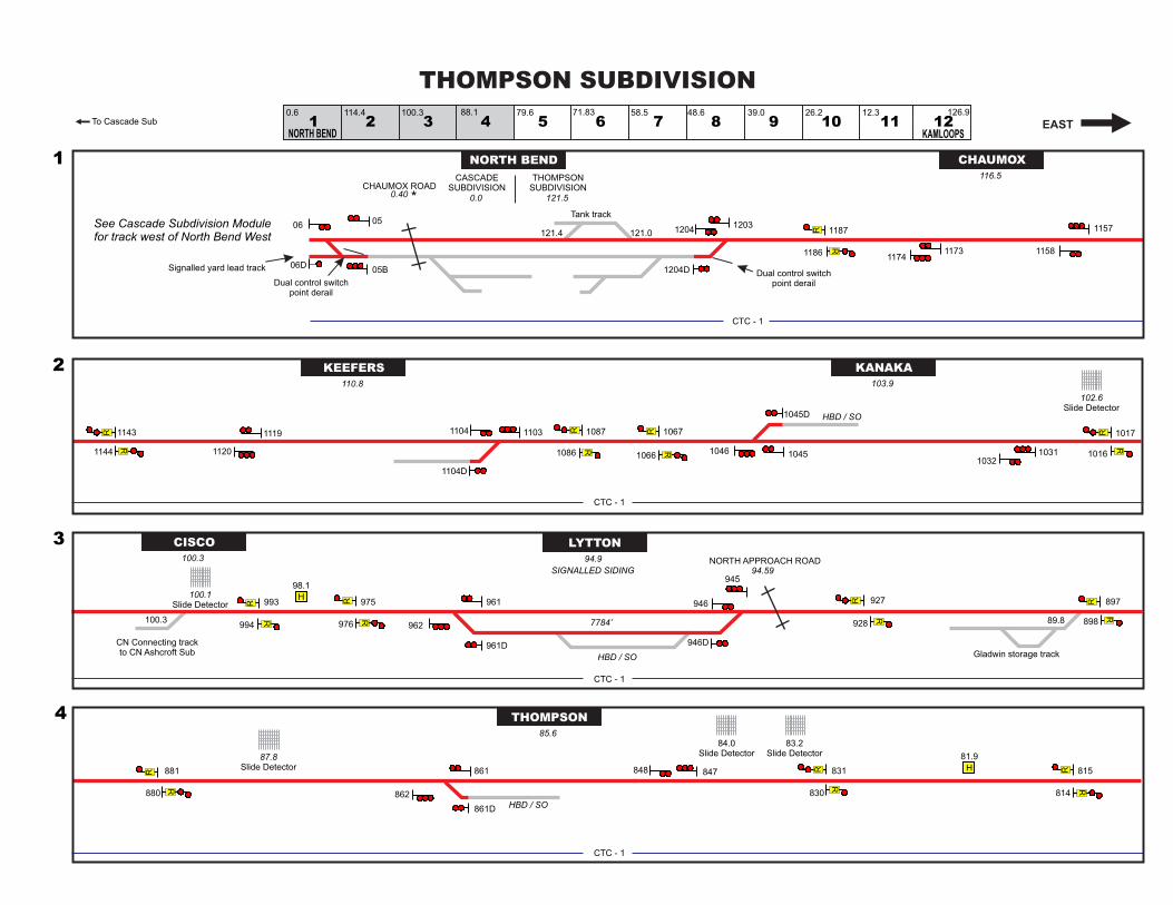
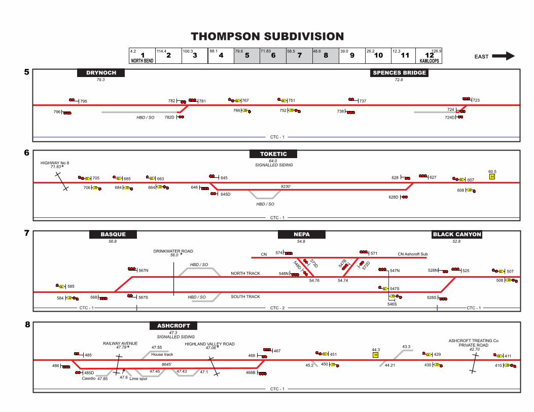
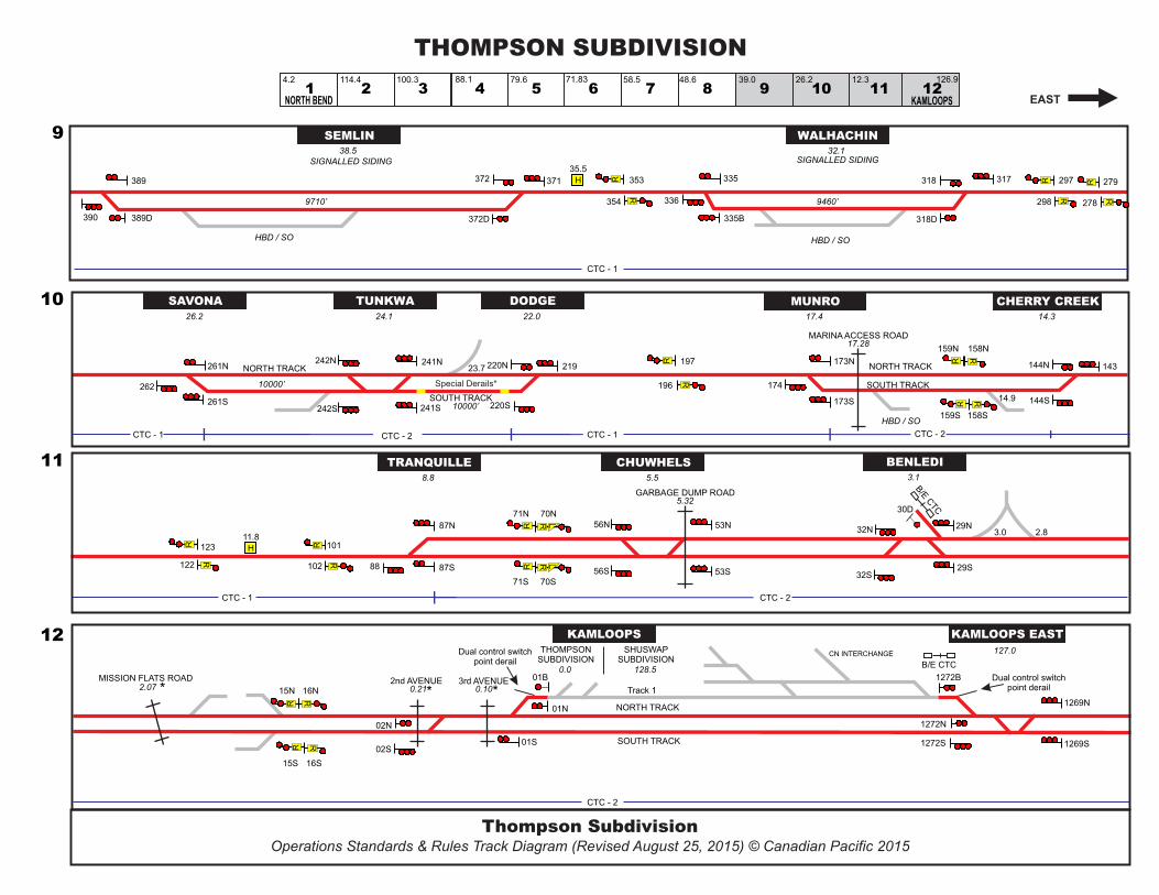


![RTC Pharma07CatalogWeb[1]](https://img.pdfslide.us/doc/110x75/55cf8de4550346703b8c6188/rtc-pharma07catalogweb1.jpg)