Embed Size (px)
Citation preview

International Research Journal of Engineering and Technology (IRJET) e-ISSN: 2395-0056
Volume: 04 Issue: 07 | July -2017 www.irjet.net p-ISSN: 2395-0072
TIME OVERRUN IN TRANSPORTATION PROJECT - A CASE STUDY OF MUMBAI MONORAIL
Praveen P Bhandekar#1 ,Dr. Ashok. B. More #2
#1PG Scholar, Department of Civil Engineering, TSSM’s P.V.P Institute of Technology SPPU Pune, India, #2Head of Department, Department of Civil Engineering TSSM’s P.V.P Institute of Technology SPPU Pune, India, ---------------------------------------------------------------------------------------------------------------------***-------------------------------------------------------------------------------------------------------
Abstract - In recent year Government of India’s Ministry of Urban planning and development had declared 100 smart cities all over the India. This dream can’t be completed without development of Maas Rapid Transit System (MRTS) in the city. For development of MRTS in the city, the viability of various MRTS must have to check economically, financially, and environmentally.
The case study of Mumbai Monorail check the viability of system in above mentioned ways and it gives satisfactory results. The study shows benefits of monorail in comparison of other MRTS. The study elaborate various planning stages such as alignment planning, station planning, land management, environmental impact analysis. It also includes the various challenges the team Monorail faced during execution. It also elaborate the cause and remedies for time delay in projects
In Mumbai Monorail study, it is observed that some activities like utility diversion, rehabilitation and resettlement will finish before actual execution of work will help in minimizing time delay. This will be further useful in construction of MRTS in various cities in scheduled time
The Study ends with the conclusion that, the activities like proper alignment planning , rehabilitation of project affected people , utility diversion should be executed first. The study also suggest about ‘Cushion Time’ during execution of work, empowerment of organization and addition of ‘Heavy Penalty Clauses’ while preparation of tender in future MRTS project.
Keywords – Smart city, MRTS, Mumbai monorail, construction challenges, time delay
1.0 INTRODUCTION
Mass Rapid transit is a high capacity public transport system fond in urban area .Mass Rapid transit system (MRTS) play a crucial role in promoting urban development. Throughout India a number of mass rapid transit systems have been implemented into the various metro cities that includes suburban railway, Metro rail, Light rail transit (LRT) in number of type, Monorail & BRTS. The Comparison of various MRTS according to their various defining features is as given below:
Serial .No.
Features Suburban Rail and Metro Rail
Mono Rail
LRT BRT
1. Line capacity (pphpd)
11,000 to 81,000
1,780 to 32,000
5832 to 20,000
11,000 to 81,000
2. Maximum Gradient
3 to 4 % 6 % 6 to 09 %
-
3. Row
requiems underground or elevated support
elevated support
elevated
minimum two lane of road
4. Coaches/Train
4 to 10 2 to 06
2 to 4 -
Serial .No.
Features Suburban Rail and Metro Rail
Mono Rail
LRT BRT
5. Operating Speed (Km/h)
25 to 60 25 to 40
18 to 040
15 to 25
6. Frequency
20 to 40 15 to 020
10 to 090
120 to 300
7. Environment impact
high noise pollution
low noise pollution
low noise pollution
medium noise pollution
© 2017, IRJET | Impact Factor value: 5.181 | ISO 9001:2008 Certified Journal | Page 1313

International Research Journal of Engineering and Technology (IRJET) e-ISSN: 2395-0056
Volume: 04 Issue: 07 | July -2017 www.irjet.net p-ISSN: 2395-0072
6
Types of MRTS
Bus Rapid Transit System (BRTS) Suburban Railway
Metro System Light Rail or Modern Tramway
2. 0 LITERATURE SURVEY
The operating vehicle on a fixed singular rail may
have been developed in 1800 century but the monorail as
a mass rapid transit system was emerged in 20th century.
The technology in the established form still not developed
in any country as it implemented in relatively small
countries like, Japan, Malaysia, and UAE. In India the
monorail system is implementing only in Mumbai city for
Chembur – Wadala – Sant Gadge Maharaj chock Corridor
,which is partly operating on Chembur to Wadala corridor.
As it have been implemented in relatively small number of
countries less researched on this transit mode
comparative to conventional rail system however some
key research does exists which is drawn upon practical
experience working with monorail. The short intimation
provided in few research papers on mass rapid transit
system.
3. 0 AIM AND OBJECTIVE
3.1 Aim:- The aim of this study is to achieve timely completion of project. So as to save valuable financial resources of country.
3.2 Objectives:-
1. To identify various causes for time delay in Mumbai Monorail Project.
2. To find out period of time delay in project. 3. To suggest the effective sequence of activities to
overcome time delay. 4. Comparative studies of time delay with the help at
time delay in Mumbai Monorail Project.
4.0 FEASIBILITY OF MONORAIL ON PROPOSED CORRIDOR.
4.1 What is Monorail?
Monorail is a guided transit mode with vehicles riding on or suspended from a single rail, beam, or tube. Vehicles normally employ rubber tyres support for guidance wheels.
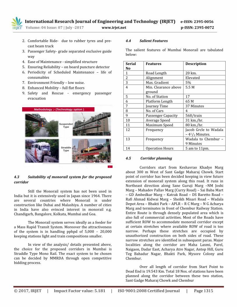
4.2 Technology option for monorail system
There are two basic classes of monorail systems:
“Supported” and “Suspended”. The term “monorail” is used
to describe almost any transit system using an overhead
structure and vehicles with arrangements of support and
guidance wheels. These vehicles run on the surface of a
rather large beam (or inside an enclosed box structure).
4.2.1 Straddle Type Monorail:
When the vehicle’s passenger compartment is above the running beam, and the structure stands on mono-beam, the system is termed a supported or straddle type monorail.
Vehicles are supported by vertically-oriented tyres rolling a top the beam way, with horizontally-oriented tyres pressing against either side of the beam way to provide stability and guidance (nearly 2 m high and 1 m wide).
Guide ways must be grade separated to accommodate rubber-tyre mono-beams and safe operation with Power rail Traction system. At-grade crossing and in-street operation are not feasible. High platforms must be provided at all stations.
Trains are articulated, 2 to 6 car units, each can be about 15 m long and 3.00 m wide, with about 60 seats and a total seated and standing capacity of about 200 passengers. With driverless operation, practical operating headways can be as short as 1.25 minutes, yielding an “ultimate” capacity of the order of 20,000 pphpd. Coaches with lower capacity (125-150) are also employed by same systems
4.2.2 Advantage of Straddle type monorail
The salient features of a straddle type monorail system are given below.
1. Running stability – easy arrangement of bogies
and wheels
© 2017, IRJET | Impact Factor value: 5.181 | ISO 9001:2008 Certified Journal | Page 1314
International Research Journal of Engineering and Technology (IRJET) e-ISSN: 2395-0056
Volume: 04 Issue: 07 | July -2017 www.irjet.net p-ISSN: 2395-0072
2. Comfortable Ride- due to rubber tyres and pre-
cast beam track
3. Passenger Safety- grade separated exclusive guide
way
4. Ease of Maintenance - simplified structure
5. Ensuring Reliability – on board puncture detector
6. Periodicity of Scheduled Maintenance – life of
consumables
7. Environment Friendly – low noise.
8. Enhanced Mobility – full flat floors
9. Safety and Rescue - emergency passenger
evacuation
10
Methodology ;- (Technology option )
Suspended
Type
Straddle
Type
4.3 Suitability of monorail system for the proposed
corridor
Still the Monorail system has not been used in India but it is extensively used in Japan since 1964. There are several countries where Monorail is under construction like Dubai and Malashiya. A number of cities in India have also evinced interest in monorail e.g. Chandigarh, Bangalore, Kolkata, Mumbai and Goa.
The Monorail system serves ideally as a feeder for a Mass Rapid Transit System. Moreover the attractiveness of the system is in handling pphpd of 5,000 – 20,000 keeping stations light and train compositions smaller.
In view of the analysis/ details presented above, the choice for the proposed corridors in Mumbai is Straddle Type Mono Rail. The exact system to be chosen can be decided by MMRDA through open competitive bidding process.
4.4 Salient Features
The salient features of Mumbai Monorail are tabulated below: Serial No
Features Description
1 Road Length 20 km. 2 Alignment Elevated 3 Max. Gradient 5% 4 Min. Clearance above
ground 5.5 M
5 No. of Station 17 6 Platform Length 65 M 7 Journey Time 37 Minutes 8 No. of Cars 4 9 Passenger Capacity 568/train 10 Average Speed 31 km./hr. 11 Maximum Speed 80 km./hr. 12 Frequency Jacob Grcle to Wadala
– 41/2 Minutes. 13 Frequency Wadala to Chembur –
9 Minutes 14 Operation Hours 5 am to 11pm.
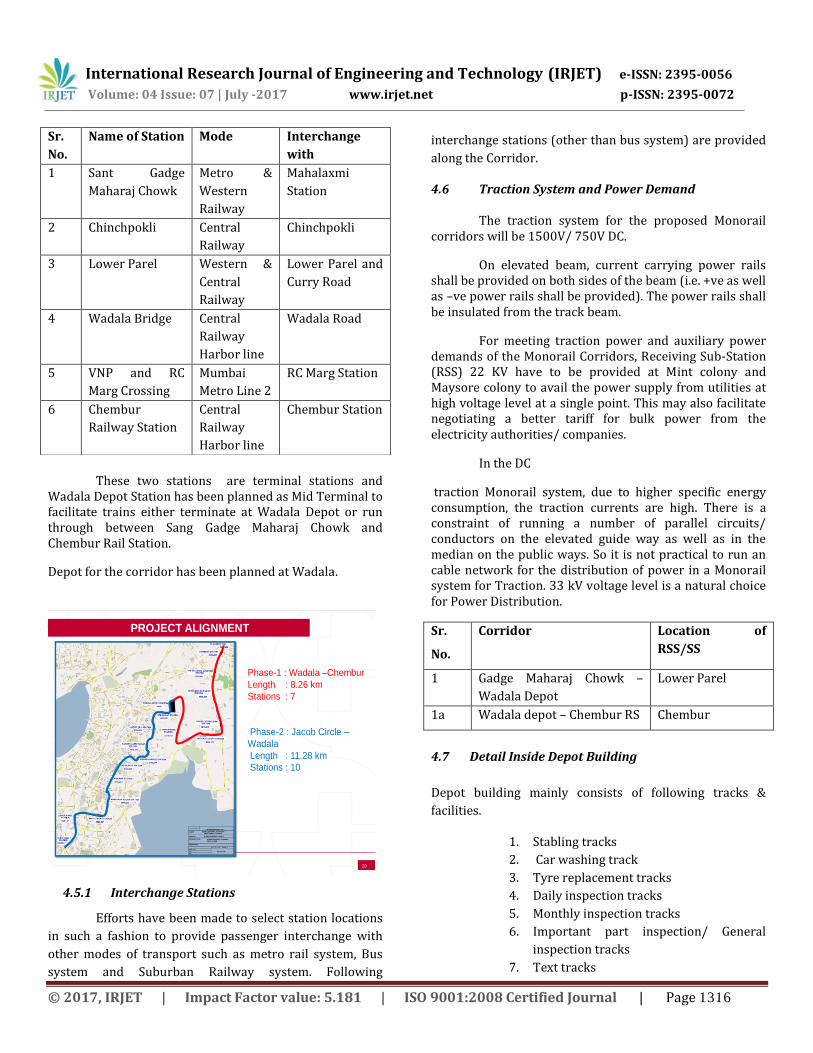
4.5 Corridor planning
Corridors start from Keshavrao Khadye Marg about 300 m West of Sant Gadge Maharaj Chowk. Start point of corridor has been decided keeping in view future extension of monorail system along this road. It runs in Northeast direction along Sane Guruji Marg –NM Joshi Marg – Mahadev Pallav Marg (Curry Road) – Sai Baba Mart – GD Ambedkar Marg – Katrak Road – DS Baretto Road – Rafi Ahmad Kidwai Marg – Sheikh Misari Road – Wadala Depot Area – Bhakti Park – APLR – R C Marg – N G Acharya Marg and terminates in front of Chembur Railway Station. Entire Route is through densely populated area which is also full of commercial activities. Most of the Roads have sufficient ROW to accommodate monorail corridor except at certain stretches where available ROW of road is too narrow. Perhaps these stretches are occupied by unauthorized construction on both sides of road. These narrow stretches are identified in subsequent paras. Major localities along the corridor are Maha Laxmi, Parel, Naigaon, Dadar East, Acharya Atre Nagar, Antop Hill, Guru Teg Bahadur Nagar, Bhakti Park, Mysore Colony and Chembur.
Over all length of corridor from Start Point to Dead End is 19.543 Km. Total 18 Nos. of stations have been planned along the corridor between these two station, Sant Gadge Maharaj Chowk and Chembur
© 2017, IRJET | Impact Factor value: 5.181 | ISO 9001:2008 Certified Journal | Page 1315
International Research Journal of Engineering and Technology (IRJET) e-ISSN: 2395-0056
Volume: 04 Issue: 07 | July -2017 www.irjet.net p-ISSN: 2395-0072
These two stations are terminal stations and Wadala Depot Station has been planned as Mid Terminal to facilitate trains either terminate at Wadala Depot or run through between Sang Gadge Maharaj Chowk and Chembur Rail Station.
Depot for the corridor has been planned at Wadala.
20
Phase-1 : Wadala –Chembur
Length : 8.26 km
Stations : 7
Phase-2 : Jacob Circle –
Wadala
Length : 11.28 km
Stations : 10
PROJECT ALIGNMENT
4.5.1 Interchange Stations
Efforts have been made to select station locations
in such a fashion to provide passenger interchange with
other modes of transport such as metro rail system, Bus
system and Suburban Railway system. Following
interchange stations (other than bus system) are provided
along the Corridor.
4.6 Traction System and Power Demand
The traction system for the proposed Monorail corridors will be 1500V/ 750V DC.
On elevated beam, current carrying power rails shall be provided on both sides of the beam (i.e. +ve as well as –ve power rails shall be provided). The power rails shall be insulated from the track beam.
For meeting traction power and auxiliary power demands of the Monorail Corridors, Receiving Sub-Station (RSS) 22 KV have to be provided at Mint colony and Maysore colony to avail the power supply from utilities at high voltage level at a single point. This may also facilitate negotiating a better tariff for bulk power from the electricity authorities/ companies.
In the DC
traction Monorail system, due to higher specific energy consumption, the traction currents are high. There is a constraint of running a number of parallel circuits/ conductors on the elevated guide way as well as in the median on the public ways. So it is not practical to run an cable network for the distribution of power in a Monorail system for Traction. 33 kV voltage level is a natural choice for Power Distribution.
Sr.
No.
Corridor Location of
RSS/SS
1 Gadge Maharaj Chowk –
Wadala Depot
Lower Parel
1a Wadala depot – Chembur RS Chembur
4.7 Detail Inside Depot Building
Depot building mainly consists of following tracks &
facilities.
1. Stabling tracks
2. Car washing track
3. Tyre replacement tracks
4. Daily inspection tracks
5. Monthly inspection tracks
6. Important part inspection/ General
inspection tracks
7. Text tracks
Sr.
No.
Name of Station Mode Interchange
with
1 Sant Gadge
Maharaj Chowk
Metro &
Western
Railway
Mahalaxmi
Station
2 Chinchpokli Central
Railway
Chinchpokli
3 Lower Parel Western &
Central
Railway
Lower Parel and
Curry Road
4 Wadala Bridge Central
Railway
Harbor line
Wadala Road
5 VNP and RC
Marg Crossing
Mumbai
Metro Line 2
RC Marg Station
6 Chembur
Railway Station
Central
Railway
Harbor line
Chembur Station
© 2017, IRJET | Impact Factor value: 5.181 | ISO 9001:2008 Certified Journal | Page 1316
International Research Journal of Engineering and Technology (IRJET) e-ISSN: 2395-0056
Volume: 04 Issue: 07 | July -2017 www.irjet.net p-ISSN: 2395-0072
8. Departure and arrival track
9. Departure inspection track
10. Drill track
11. Maintenance vehicle stabling track
12. Workshop
13. Operation control Center
14. Water supply/ Sewer line
Rail transit system handles large number of passengers. Ticket issue and fare collection play a vital role in the efficient and proper operation of the system. To achieve this objective, ticketing system shall be simple, easy to use/ operate and maintain, easy on accounting facilities, capable of issuing single/ multiple journey tickets, amenable for quick fare changes and require overall lesser manpower. In view of above, computer based automatic fare collection system is proposed. This helps in keeping the station area litter free Automatic fare collection systems have the following
advantages:
1. Less number of staff required. 2. Less possibility of leakage of revenue due to 100%
ticket check by control gates. 3. Recycling of ticket fraudulently by staff avoided. 4. Efficient and easy to operate, faster evacuation both in
normal and emergency. 5. System is amenable for quick fare changes. 6. Management information reports generation easy. 7. System has multi-operator capabilities. Same Smart
Card can be used for other applications also
4.0 MUMBAI MONORAL PLANNING AND MANEGMENT
5.1 Alignment Planning
For the Mono Rail system with a maximum speed of
80 kmph, a minimum Horizontal curve radius of 300 m is
considered desirable with allowable Cant (%) = V2/1.27 R
≤12 and cant deficiency (Cd) = 5%. However, such radius is
not achievable on the proposed corridor. At certain
locations, radius of 50 m is also provided, which would
necessitate reduction in permissible speed,
a) Horizontal Curves
- Desirable Minimum curve radius in mid section :100 m
- Absolute Minimum curve radius in mid section :50 m
- Minimum curve radius at stations :300 m
- Permissible cant (Ca) % :12
- Cant deficiency (Cd) : 5%
b) Transition Curves
-Generally a Clothoid curve is adopted for transition
curves.
- Desirable length of Transitions of Horizontal :V3/14 R m Curves (rate of change of angular accn 0.3 m/s2/s) - Minimum length of transition curves:15 m - Minimum straight length between two Transition curves: 15 m or NIL - Minimum curve length between two Transition curves: 15 m or Nil - Curves overlap between transition curves and vertical curves are permitted but will require casting/ fabrication of beam to required profile.
However, it may not be possible to provide transition curves of desirable length due to constraints of circular curve length or otherwise. At such locations the permissible speed may be restricted due to comfort parameter.
5.2 Station Planning
Stations are planned as minimal structures required to facilitate the passengers board and alight from the monorail coach and negotiate the street to platform height with the maximum ease and within minimum time. Hence it is proposed that the monorail station will be more like a ‘big bus stand’ as opposed to being a ‘small metro station’.
Salient features of a typical station are as follows: 1. No passenger’s concourse has been proposed. Passengers will directly reach the platforms from street. 2. Two foot over bridges under the track beams will connect the two sidewalks as pedestrian links. 3. Ticket vending is expected to be by Passenger Operated Machines (POMs) at the foot over bridges. AFC and manual ticketing proposed at each station. No separate ticket vending rooms are proposed at the stations. 4. Platforms are 95 m long adequate to receive a 6 coach monorail train. Due to road width constraints, platform supporting columns have to be placed at least 19 m apart, which makes the platforms about 8.5 m wide. The additional space on the platforms thus available is proposed to accommodate all the S & T and Electrical equipment that may be required at the station at the four corners since no mezzanine similar to a metro station is provided. 5. The platform level has adequate assembly space for passengers for both normal operation conditions and a recognized abnormal scenario.
4.8 Automatic Fare Collection
© 2017, IRJET | Impact Factor value: 5.181 | ISO 9001:2008 Certified Journal | Page 1317

International Research Journal of Engineering and Technology (IRJET) e-ISSN: 2395-0056
Volume: 04 Issue: 07 | July -2017 www.irjet.net p-ISSN: 2395-0072
6. Automatic Fare Collection (AFC) gates, if required can be located at the starting point of stairs at platform level. 7. Station entrances are located with particular reference to passenger catchment points and physical site constraints within the right-of-way allocated to the MRTS. 8. Office accommodation, operational areas and plant room space is required at each station. The functions of such areas are given below 5.3 Land Management Land will be Required for the following main Components 1.Monorail Structure (including Route Alignment), Station Building, Platforms, Entry/ Exist Structure, Traffic Integration Facilities, Depots etc. 2.ASS/Traction Sub-Station 3.Radio Towers 4.Temporary Construction Depots and work sites 5.4 Environmental Impact Assessment A) Positive Environmental Impact
Based on project particulars and existing environmental conditions, potential impacts have been identified that are likely to result from the proposed project and where possible these have been quantified. The positive environmental impacts are described below : 1.Traffic congestion reduction . 2.Quick service and safety 3.Less fuel consumption 4.Reduction in Air Pollution 5.Carbon Dioxide Reduction 6.Savings In Road Infrastructure 7.Employment opportunities B) Negative Environmental Impacts
Based on project particulars and existing environmental conditions. Potential negative impacts likely to result from the proposed development have been quantified. Negative impacts have been listed under the following headings ; a)Impacts due to project location
1.Change of Land Use 2.Loss of Trees 3.Loss of Historical and Cultural Monuments 4.Loss of community property resources b)Impacts due to construction works,
1 Soil Erosion and Health Risk at Construction Site 2Traffic Diversion and Risk to Existing Buildings 3 Impact on Water Quality 4 Increased Water Demand
5Disposal of soil during construction 6.0 CONSTRUCTION CHALLENGES
During Monorail construction challenges faced at
every level, start from beginning at boring of pile up to
successful running of the trains.
The major construction challenges faced and their
successful solutions are listed here to get on overall idea.
6.1 Right of way:
To clear the right of way 120 Nos. of families were shifted to new location. This shifting activity consumer lot of valuable time of the project period. Which causes the delay in the completion of the period.
During this shifting activity the officers have to faces falls criminal cases, court cases, which demoralize the officers at certain extent, but continuous motivation & support from superior staff leading to completion of the project.
The second major hurdle to clear the right of way is the infringement of temple at Curry Road (ch. 1760). The pier location which come exactly center of the temple and there was strong opposition for shifting of temple location the pier location have to shifter as shown in figure.
24
120 Nos of Families were shifted to New location in the city to Clear ROW
Right Of Way
6.2 Trees Cutting:
This is the major challenges to cool down the oppose of
tree cutting raised by NGO/ People/ Local residents. This
challenge is overcome by planting the town time no of tree
cut.
© 2017, IRJET | Impact Factor value: 5.181 | ISO 9001:2008 Certified Journal | Page 1318

International Research Journal of Engineering and Technology (IRJET) e-ISSN: 2395-0056
Volume: 04 Issue: 07 | July -2017 www.irjet.net p-ISSN: 2395-0072
6.3 Removal of Encroachment:
The removal of encroachment along the alignment is giant task carried out by the monorail team. This time also the monorail team has to face physical assault, false animal cases/ court cases but still the team doesn’t demoralize due to strong support from the higher authority.
The major encroachment locations are listed as below.
i) Mint Colony ii) Ambedkar Nagar
iii) Naigaon iv) Dadar East v) Wadala bridge
vi) A.A. Nagar vii) Bhakti Park
viii) Mysore colony ix) Fertilizer town ship x) VNP & RC Marg
6.4 Diversion of utilities:
The Herculean task of utility diversion have to carried out monorail team at various construction stages. The main problem faced by Monorail team during diversion of utilities is lack of information about various underground utilities by various organization.
In some area the sewer/ storm water drains was constructed during British era. The old map is not available with local bodies so the utility identification was carried out by digging trail trenches at various location.
After trenching in some location bunch of cables of different utilities were found to identify the utility and the owner of the utility a ‘Joint site inspection’ and joint meeting with various organisation were conducted and plan for utility diversion is finalised.
‘Due to utility diversion plan the design of the pile cap have to change continuously which further delay the project.
28
• Lack of information
• Identification of Utilities
• Continuous change of Designs continuously
• Shifting utilities, if necessary
Utilities – Herculean task
6.5 Permission /clearance from various organization
Permission clearness should be sought from
various agencies. viz. Telephone, Mobile, Gas, Drainage,
Communication cable, sewer pipe lines, water pipe lines
power cables etc.
At the least 15 utility agencies will come into
picture the mayor clearance required are listed as below.
1. Forest department clearance 2. Environmental clearance 3. Radio frequency clearance from ministry (SACFA) 4. EIG clearance for power traction and building
installation. 5. Safety certification from statutory bodies. 6. Five clearance from five department.
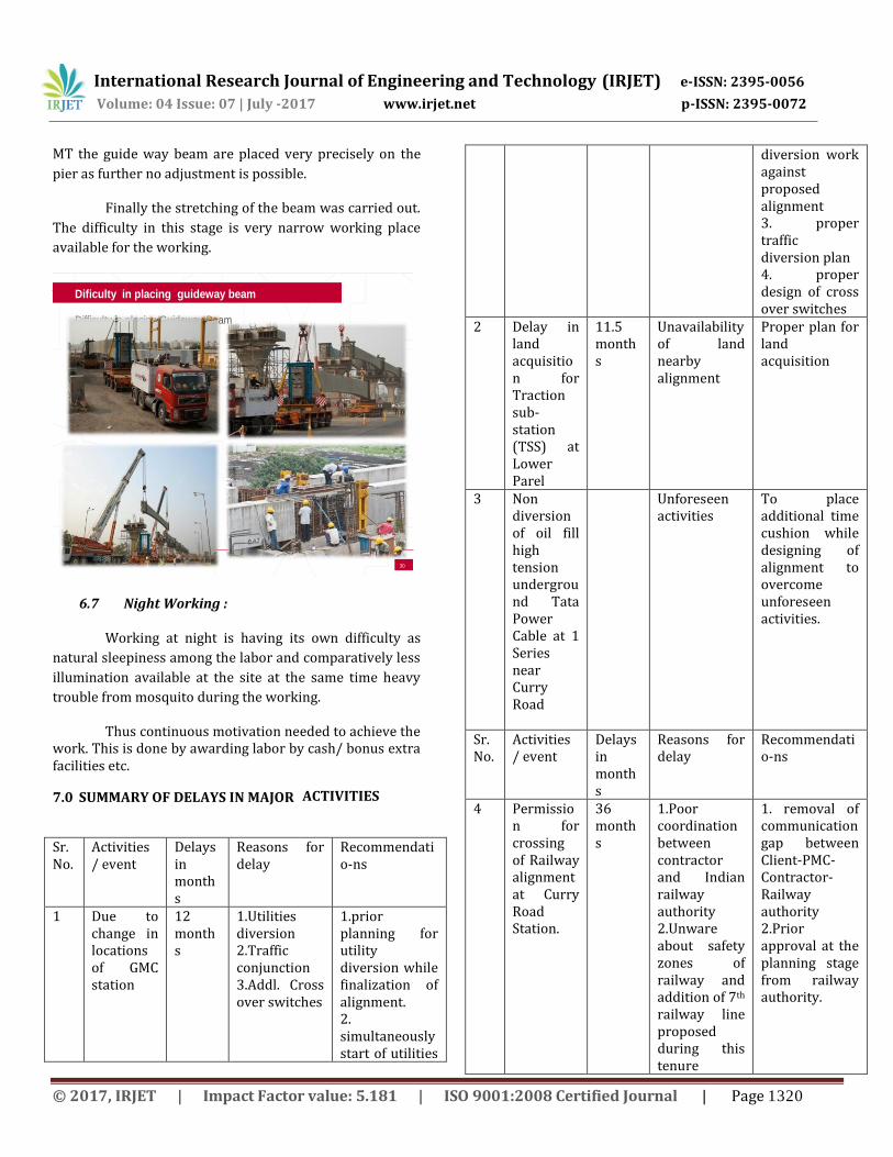
6.6 Difficulty in placing guide way beam
The weight of guide way beam is nearly about 80
MT. The guide way beam was casted in casting yard
located at Wadala. Thus this guide way beam need to be
transferred at various pier location.
This transportation was carried out by specially
designed vehicles having large capacity to transport the
beam (as shown in figure). This beam was transported in
height only to avoid traffic consumption. In some places
the road pavement was strengthen to bear that much load
coming on road. The path of the vehicle is selected in such
a way that to avoid flyovers/ ROB coming on the way.
When the beam is transported to selected pier it
was lifted by two cranes having capacity more than 100
© 2017, IRJET | Impact Factor value: 5.181 | ISO 9001:2008 Certified Journal | Page 1319
International Research Journal of Engineering and Technology (IRJET) e-ISSN: 2395-0056
Volume: 04 Issue: 07 | July -2017 www.irjet.net p-ISSN: 2395-0072
MT the guide way beam are placed very precisely on the
pier as further no adjustment is possible.
Finally the stretching of the beam was carried out.
The difficulty in this stage is very narrow working place
available for the working.
30
Difficulty in placing Guideway Beam
Dificulty in placing guideway beam
6.7 Night Working :
Working at night is having its own difficulty as
natural sleepiness among the labor and comparatively less
illumination available at the site at the same time heavy
trouble from mosquito during the working.
Thus continuous motivation needed to achieve the work. This is done by awarding labor by cash/ bonus extra facilities etc.
7.0 SUMMARY OF DELAYS IN MAJOR ACTIVITIES
Sr. No.
Activities / event
Delays in months
Reasons for delay
Recommendatio-ns
1 Due to change in locations of GMC station
12 months
1.Utilities diversion 2.Traffic conjunction 3.Addl. Cross over switches
1.prior planning for utility diversion while finalization of alignment. 2. simultaneously start of utilities
diversion work against proposed alignment 3. proper traffic diversion plan 4. proper design of cross over switches
2 Delay in land acquisition for Traction sub-station (TSS) at Lower Parel
11.5 months
Unavailability of land nearby alignment
Proper plan for land acquisition
3 Non diversion of oil fill high tension underground Tata Power Cable at 1 Series near Curry Road
Unforeseen activities
To place additional time cushion while designing of alignment to overcome unforeseen activities.
Sr. No.
Activities / event
Delays in months
Reasons for delay
Recommendatio-ns
4 Permission for crossing of Railway alignment at Curry Road Station.
36 months
1.Poor coordination between contractor and Indian railway authority 2.Unware about safety zones of railway and addition of 7th railway line proposed during this tenure
1. removal of communication gap between Client-PMC-Contractor- Railway authority 2.Prior approval at the planning stage from railway authority.
© 2017, IRJET | Impact Factor value: 5.181 | ISO 9001:2008 Certified Journal | Page 1320

International Research Journal of Engineering and Technology (IRJET) e-ISSN: 2395-0056
Volume: 04 Issue: 07 | July -2017 www.irjet.net p-ISSN: 2395-0072
5 Delay due to land acquistation from Mumbai Port Trust and Indian Railway crossing pier 1H4A-1H12
36 1.Poor Coordination and planning 2.Delay due to land handover to MMRDA by MBPT 3.Rehabilaion of existing tenant at old building very near to alignment.
1.Proper alignment designing 2.Prior planning of rehabilitation plan
6. Delay in Manufacturing of rolling stock
60 1.Design issues as per Indian Safety norms and IRC loading Condition 2.Remodeling and Redesign takes multiple years
Heavy Penalty Condition in tender should be implemented.
7 Delay in permission for Tree Cutting
18 Delay occurred by Tree Authority
Single Window Clearance as implemented in DMRC Delhi
8 Delay due to taxation Complexity
24 1.Delay in decision making process for tax exemption for particular activity 2.Mltiple taxation system .
Single taxation system like GST
8.0 CONCLUSION
The first phase of Mumbai Monorail i.e. from
Chembur to Wadala was completed on January 2014. In first phase it is covering the area of industrial establishment like Bharat Petroleum Colony, Fertilizer township etc, so the ridership for this phase is very low and limited up to pick hours only.
In present status all the civil works of alignment
and station is 100% completed and the balancing mechanical, electrical, electronic work will be expected to
be completed up to Dec 2017 .Once this work will completed in all respect, the monorail will get full ridership & project will be economical and financial feasible. The following point should be consider while developing any other MRTS in city.
1. Alignment for the work should be fix consoling all
possible factor like probable utility division, retaliation at project attached people, land acquistation, traffic division etc.
2. After this the proper plan for utility diversion, rehabilitation of project affected people, land acquisition should be prepared before execution of work.
3. ‘A cushion time’ should be kept to overcome unforeseen activities while planning for execution.
4. Tender document should be prepared which include ‘heavy penalty condition’ for time delay by contractor and consultant.
5. Most of the MRTS technology are new in India so that a planned documentation for human resource management should be prepared.
6. The permissions / clearance / liasioning activity should be carried out before execution of the work.
7. Empowering of implementing authority (MMRDA) like DMRC, Delhi which help in implementation of single window clearance system for getting various permissions/clearance.
8. The manufacturing of monorail coaches in India under ‘Make in India’ initiative by Govt. which help in reduction in time delay upto certain extent.
9. The implementation of GST will help in implementation of single taxation system for monorail which helps in reduction time of implementation in future.
ACKNOWLEDGEMENT The Author of this paper are highly obligated to the Monorail Unit of Transport and Communication Division of Mumbai Metropolitan Region Development Authority, also to the Department of Civil Engineering, Padmabhushan Vasantdada Patil Institute of Technology, Bavdhan, Pune. The authors would like to express their deep sense of gratitude toward Deputy Engineer-I of Mumbai Monorail Unit. REFERENCES
1. Patrick Miller, S.C Wirasinghe,Lima kattan,Alex de Barros”Monorail for Sustainable transportation-A Rivew” CSCE -2014, General Conference, page no181-1 to 181-9
© 2017, IRJET | Impact Factor value: 5.181 | ISO 9001:2008 Certified Journal | Page 1321

International Research Journal of Engineering and Technology (IRJET) e-ISSN: 2395-0056
Volume: 04 Issue: 07 | July -2017 www.irjet.net p-ISSN: 2395-0072
2. RITS International “Feasibility Report on Mumbai Monorail” 2008,Chapter 1 to 5
3. Delhi Metro Rail Corporation (DMRC)”Detail Project Report on Kozhikode monorail Project” June 2012,Chapter 3 page no 1 to 3
4. World Bank “Transportation Strategy Review” July 2010,page no 51
5. Rewati Marathe and N.D Hajiani “Monorail a Guided system be an approving transit system in developing countries like India “ IJSRD Vol-3 March 2015“ IJSRD Vol-3 March 2015 page no 657 to 660
6. Rewati Marathe and N.D Hajiani” A review of research on Monorail as an alternative Mass Rapid Transit System” IJSRD-2013 page no 276
7. 7.Ashish Varma and S.l Dhingara “ Suitability of alternate system for Urban mass transportation for Indian Cities” Transport Europel page no 4 to 6
© 2017, IRJET | Impact Factor value: 5.181 | ISO 9001:2008 Certified Journal | Page 1322


![Dynamic Response Analysis of the Straddle-Type Monorail ... · et al. [4] investigated the dynamic responses of the straddle monorail train and the degree of riding comfort based](https://img.pdfslide.us/doc/110x75/5e6ef519781edc6895610ac1/dynamic-response-analysis-of-the-straddle-type-monorail-et-al-4-investigated.jpg)