Embed Size (px)
Citation preview

INTELLIGENT REFERENCE/TM-4
TIME & FREQUENCY SYSTEM
USER MANUAL
MANUAL PART NUMBER: 40013-001
SPECTRUM INSTRUMENTS, INC. 570 E. ARROW HIGHWAY
SUITE D SAN DIMAS, CA 91773
Copyright ©2004 SPECTRUM INSTRUMENTS, INC.
Spectrum makes every effort to insure that the information in this document is accurate, but makes no claim to that effect and does not guarantee accuracy. This information is offered as-is, and Spectrum cannot be
held responsible for any inaccuracies. Specifications, features and operational characteristics of the described product are subject to change without notice.
ii
WARNINGS AND NOTICES NAVIGATING WITH THE PRODUCT The Intelligent Reference/TM-4™ is intended to be used primarily as a precise time and frequency instrument, even though it is capable of position location and navigation using the GPS system. Users are strongly advised to use good judgment if using this instrument for navigation. The user should never rely solely on any one source of information for navigation and should be aware that the position accuracy obtained from any GPS receiver can be affected by numerous sources of error such as satellite geometry, selective availability, satellite health, and electromagnetic interference. Published accuracy specifications are to be used only as a guide and are not guaranteed. FCC NOTIFICATION This equipment has been tested and found to comply with the limits for a Class A digital device, pursuant to Part 15 of the Federal Communications Commission Rules & Regulations. These limits are assigned to provide reasonable protection against harmful interference when the equipment is operated in a commercial environment. This equipment generates, uses, and can radiate radio frequency energy and, if not installed and used in accordance with this user manual, may cause harmful interference to radio communications. Operation of this equipment in a residential area may cause harmful interference, in which case the user will be required to correct at his own expense. DC POWER CONNECTION Exercise caution when connecting a power source to the Intelligent Reference/TM-4™. Make sure to observe the correct polarity, voltage and pin connection. Applying power to the unit with incorrect polarity or voltage or to the incorrect pin will damage the unit, and it will then require factory repair. Damage due to incorrect powering of the Intelligent Reference/ TM-4™ is not covered by the warranty. Refer to Section 7 of this manual for complete information.

iii
TABLE OF CONTENTS
SECTION 1 - INTRODUCTION........................................................... 1
HOW TO USE THIS MANUAL ................................................................................ 1 THE GLOBAL POSITIONING SYSTEM (GPS)............................................................. 1 INTRODUCTION TO THE INTELLIGENT REFERENCE/TM-4........................................ 2
SECTION 2 - UNPACKING AND INSTALLATION................................ 6
PACKING LIST ..................................................................................................... 6 ANTENNA INSTALLATION..................................................................................... 6 INTELLIGENT REFERENCE/TM-4 INSTALLATION ..................................................... 7 CONNECTION TO A PERSONAL COMPUTER ........................................................... 7 POWER INPUT .................................................................................................... 7
SECTION 3 - QUICK START INSTRUCTIONS ..................................... 9
SECTION 4 - OPERATING MODES AND FUNCTIONS....................... 11
START-UP SEQUENCES.......................................................................................11 OSCILLATOR MODES ..........................................................................................12 TIMING MODES..................................................................................................12 MASK ANGLE ....................................................................................................13 MAP DATUMS ...................................................................................................13 USER TIME BIAS.................................................................................................14 ASCII SERIAL TIME/NTP/NMEA MESSAGES............................................................14 EVENT TIME-TAG (ETT)........................................................................................15 PROGRAMMED OUTPUT PULSE (POP)..................................................................16 HARDWARE FAULT MONITORING ........................................................................16 IRIG OR OTHER SERIAL TIME CODE OPTION ..........................................................17 NETWORK TIME PROTOCOL OPTION....................................................................17 AUXILIARY FREQUENCY OUTPUT OPTION .............................................................17 SYNTHESIZED TIMING PULSE OUTPUT OPTION .....................................................18 ACCURACY CONSIDERATIONS.............................................................................18 OPERATING SUGGESTIONS .................................................................................21 STAND-ALONE OPERATION .................................................................................21 MASTER RESET..................................................................................................22
SECTION 5 - OPERATION OF THE INTELLIGENT REFERENCE/TM-4 23
SOFTWARE OVERVIEW.......................................................................................23 COMPUTER REQUIREMENTS ...............................................................................23 INITIALIZATION FILE ............................................................................................23 MAIN SCREEN....................................................................................................24 RECEIVER STATUS PANEL ...................................................................................24 TIME AND DATE PANEL ......................................................................................26 POSITION DATA PANEL.......................................................................................26 TIMING STATUS PANEL.......................................................................................27 ALARMS AND INDICATORS PANEL.......................................................................27 OPERATIONAL SESSION......................................................................................28 START-UP..........................................................................................................28 SETTING OPTIONS..............................................................................................29 EVENT TIME-TAG OPERATION..............................................................................29 PROGRAMMED OUTPUT PULSE OPERATION .........................................................30 REMAINING OPERATIONS....................................................................................30
iv
SECTION 6 - COMMUNICATING WITH THE TM-4.......................... 31
CONTROL PORT.................................................................................................31 COMMUNICATION MODES ..................................................................................31 MESSAGE FORMATS AND PROTOCOL..................................................................31 MESSAGES FROM THE HOST ..............................................................................32 MESSAGES FROM THE INTELLIGENT REFERENCE/TM-4 ........................................36
SECTION 7 - HARDWARE INFORMATION....................................... 42
FRONT PANEL....................................................................................................42 LED COMBINATIONS AND THEIR MEANINGS.........................................................43 REAR PANEL CONNECTORS AND FUNCTIONS.......................................................43 OTHER HARDWARE CONSIDERATIONS.................................................................46
SECTION 8 - IN CASE OF DIFFICULTY ............................................ 49
CONTACTING SPECTRUM ...................................................................................49 LIMITED WARRANTY ..........................................................................................49 RETURNING EQUIPMENT FOR REPAIR...................................................................50
APPENDIX A - SPECIFICATIONS.................................................... 51
Page 1
SECTION 1 - INTRODUCTION HOW TO USE THIS MANUAL You are strongly encouraged to read this manual thoroughly before installing and operating the Intelligent Reference/TM-4™. The instrument, coupled with the supplied computer software, provides a number of advanced and useful features. To achieve maximum performance, these features require a degree of understanding on the part of the user. This manual is organized into logical sections and can be read straight through from cover to cover. However, each section covers a single topic or related set of topics and you may feel free to skip around if you wish. If you are not familiar with GPS timing instruments and the Intelligent Reference family of products in particular, you should read this manual carefully before attempting to install or operate the Intelligent Reference/ TM-4™. Pay particular attention to Section 2 for unpacking and installation instructions, Section 4 for operating modes and functions, Sections 5 & 6 for operating instructions, and Section 7 for hardware information. If you are an experienced user, you should read the last part of this section entitled “Introduction to the Intelligent Reference/TM-4.” It will quickly familiarize you with the functional capabilities of the instrument. You can then browse the remainder of the manual to get a feel for its contents and organization. THE GLOBAL POSITIONING SYSTEM (GPS) The Global Positioning System (GPS) consists of a constellation of satellites orbiting at altitudes of approximately 10,900 nautical miles along with ground stations which monitor and control the system. The system consists of 21 active satellites and three in-orbit spares each of which orbit the earth twice per day. The design of the constellation is such that at least four satellites are in view at all times from all places on the earth, thus providing continuous, world-wide, three-dimensional navigational capabilities. Each satellite continuously transmits encoded signals in what is called the L Band at 1575.42 MHz (L1) and 1227.6 MHz (L2). Most commercial GPS receivers use only the L1 signal. Each satellite modulates its L1 signal with a unique pseudo-random spreading code (PRN). It is this unique modulation that allows a receiver to track a particular satellite while ignoring the others even though all satellites broadcast on the same frequency. There is also a 50 bit-per-second data message superimposed on the L1 signal which contains information necessary for a receiver to provide navigation and time-transfer. For two-dimensional navigation, a receiver must track a minimum of three satellites. This allows the receiver to determine the position (latitude & longitude) and time. The 21 satellite constellation provides very reliable, two-dimensional navigation for a user whose antenna has a reasonably clear view of the sky. For three-dimensional navigation, a receiver must track a minimum of four satellites. This allows the receiver to determine the position (latitude, longitude & altitude) and time. The 21 satellite constellation provides excellent three-dimensional navigation with only occasional outages as long as the antenna has a clear view of the sky and is not obstructed. If navigation is not required because the user position is known, precise time can be derived by tracking only one satellite. In this case, it is easy to see that the reliability of time information will be very high even in situations where the antenna has an obstructed view of the sky. The satellites have on-board Cesium atomic clocks, which provide a very stable time reference for determining the time synchronization of the radio transmissions from the satellite. In addition, ground stations closely monitor the performance of these clocks and provide fine corrections to the on-board time keeping. These corrections are available in the transmitted data stream for use by receivers on the ground.
Page 2
Each satellite broadcasts a 50 bit-per-second data stream, which contains an almanac for the entire constellation and precise ephemeris data for that particular satellite. Also transmitted is the precise time-of-transmission of a particular epoch in the data stream. The carrier is modulated with this data stream and also with a pseudo-random spreading code, which is unique to that satellite. By correlating an internally generated (but time-shifted) replica of the spreading code to the incoming signal, a receiver can recover the carrier, read the data stream, and measure the propagation time of the signal from the satellite to the receiver relative to the receiver's own internal clock. This time is directly related to the distance from receiver to satellite (known as the pseudo-range) by the speed of light. With this information available from three satellites, the receiver can first calculate the exact position of the satellites at the time of transmission and then determine the receiver position in two dimensions as well as time by essentially solving three equations in three unknowns. If the information is available from four satellites, the receiver can determine the receiver position in three dimensions as well as time by essentially solving four equations in four unknowns. INTRODUCTION TO THE INTELLIEGNT REFERENCE/TM-4 The Intelligent Reference/TM-4™ is a complete GPS time & frequency system offering the following features and performance:
• State-of-the-art 12 channel GPS technology. • Spectrum’s exclusive FastStart™ technology offers high accuracy within just minutes of start-up. • Intelligent Holdover™ function provides near-Rubidium stability during GPS unavailability. • GPS-disciplined ovenized oscillator with very low phase noise. • High spectral-purity 10 MHz sine wave output. • MTIE Stratum-1 compliance with frequency accuracy of 1x10-12 (long-term). • Timing accuracy of ±25 ns PTP. • Standard one pulse-per-second (1 PPS) output with separate ASCII serial time message. • Static and dynamic timing modes. • Auto Survey position averaging mode. • Timing information derived from all satellites tracked with only one satellite required in
static timing mode. • RS-232 control interface for control by a host computer. • Optional low-cost VCXO in place of OCXO. • Two multiplexer outputs. Mux output 1 supplies one of six selectable TTL outputs slaved to the
primary frequency reference: 1, 10, and 100 kHz, and 1, 5, and 10 MHz. In addition, Mux1 can also supply a TTL level PPS output or optionally be configured to supply baseband IRIG time code. Mux output 2 can supply 10 MHz or PPS at TTL levels, mirror Mux1’s output, or may optionally be configured to supply a custom output.
• NMEA message capability (subset). • Optional very wide range frequency synthesizer output slaved to primary reference. Consult factory
for specific application. • Optional second sine wave output, either identical to or independent of primary frequency, up to 100
MHz. • Optional auxiliary frequency output such as 1.544 MHz or 2.048 MHz slaved to the primary frequency
reference. Virtually any common frequency may be chosen. • Optional synthesized timing pulse output coherent with 10 MHz output and synchronized to 1 PPS.
This may be virtually any frequency up to 100 kHz, including frequencies such as 216 2/3 Hz.
Page 3
• Simultaneous Event Time-Tag (ETT) and Programmed Output Pulse (POP) functions, each with 100 ns resolution. (Note that some TM-4 units do not offer simultaneous capability. In these units, only one function may be enabled at any given time.)
• Optional Type 11 Network Time Protocol output. • Optional IRIG B (or other time code) serial time code output (TTL and modulated). • Windows®-based control/display software. • Front panel indicators for power status, reference ready, and alarm status. • 9 to 35 VDC operation with rechargeable lithium battery back-up for GPS data.
The Intelligent Reference/TM-4™ consists of a twelve-channel GPS timing receiver integrated with proprietary microprocessor-controlled timing and interface logic. A separate GPS antenna is required. The GPS receiver simultaneously tracks all available satellites. The microprocessor-controlled timing and interface logic derives precise timing information from these satellites and provides additional features including the standard 1 PPS output and associated ASCII serial time message, external event time-tag, programmed output pulse, optional IRIG B serial time code generator and other optional features and outputs. The timing and interface logic also controls an ovenized 10 MHz crystal oscillator (or VCXO) and additional clock features. The standard timing antenna (if supplied) is an all-weather, high-performance, high noise immunity patch design with an integrated low-noise preamplifier. It is supplied with 50 feet of RG-58 cable, and is designed to be attached to a standard marine thread (1.0-14UNS2A) pole. Options include a flush mounted version, an adapter that allows attachment to an unthreaded pole up to 1.25" in diameter and various antenna mounts. Pre-amplifier power is supplied from the unit over the coaxial cable center conductor. Control and operation of the Intelligent Reference/TM-4™ is handled through the control interface. Consisting of a standard RS-232 serial channel implemented in a VGA-style HD-15 D-sub connector, this accommodates a wide variety of host computers and equipment, including any personal computer or compatible with a serial communications port. The user may make use of the port either by wiring up his own cable or connection or by using the optional breakout board or adapter cable, which will bring the serial connections out to a standard 9-pin D-sub connector. All communications to and from the unit utilize a series of compact ASCII messages which allow the host to make changes to the operating parameters and read GPS tracking, status, and timing information. The Intelligent Reference/TM-4™ is capable of autonomous operation without connection to a host computer. Once power is applied, the unit requires no intervention to acquire satellites and provides the basic time and frequency functions based on factory default settings. A host computer may be connected for initialization purposes and left connected to monitor the system operation. The host may be disconnected at any time, in which case the unit will continue to operate normally with the configuration in effect at that time. Subsequent power-on starts use the last configuration in effect when power was turned off, with the exception of POP settings. POP settings are not restored after a power cycle. The TM-4 features two timing modes - static and dynamic. Static timing mode may be used when the user is stationary and position and altitude are known. Up to twelve satellites are used to derive timing information; however, only one satellite needs to be tracked to operate in this mode. Dynamic timing mode is used when the user is not stationary or when position or altitude is not known. In this mode, the unit continuously computes the position and derives timing information from as many as twelve satellites. The TM-4 also supports Auto Survey mode, where 10,000 position measurements are averaged and the unit then automatically put into static timing mode. A GPS-disciplined ovenized crystal oscillator (OCXO) is incorporated in the Intelligent Reference/TM-4™ to provide a very precise and stable frequency reference. After a few hours of tracking GPS signals, the accuracy of this source approaches that of the Cesium clocks on the GPS satellites. The output frequency is 10 MHz, and both sine wave and TTL outputs are provided. The sine wave output is of

Page 4
extremely high quality in terms of phase noise and spectral purity, and is ideal for use as the primary source for driving local oscillator synthesizers in wireless communications systems. There are two user-settable multiplexer outputs incorporated in the Intelligent Reference/TM-4™. Mux1 generates a precise TTL frequency output that is slaved to the primary 10 MHz output. One of six frequencies may be selected for output: 1 kHz, 10 kHz, 100 kHz, 1 MHz, 5 MHz or 10 MHz. Also, Mux1 can be programmed to output PPS or optional IRIG time code. The second multiplexer can supply a 10 MHz TTL signal, PPS, a mirror of the output of Mux1 or an optional custom signal. The Intelligent Reference/TM-4™ provides for an auxiliary frequency output, generated by a phase locked loop (PLL) synthesizer in the unit. This output is available as a factory option and virtually any common frequency is available. Examples include frequencies such as 1.544 MHz and 2.048 MHz. This output retains the accuracy and stability of the primary 10 MHz output, and its stability meets the MTIE requirement for a Stratum-1 primary clock source. Another advanced feature of the TM-4 is an optional very wide range frequency synthesizer. This allows the TM-4 to generate a factory-set frequency of the user’s choice, slaved to the primary frequency reference. This output retains the precision and quality of the primary reference and can be almost any frequency desired up to approximately 40 MHz. Spectrum must be consulted with requirements prior to this feature being available in the unit. Two of the most advanced features of the unit are the Intelligent Holdover™ function and Spectrum’s exclusive FastStart™ technology. Intelligent Holdover™ is an advanced oscillator control method that learns the unique operating characteristics of the particular oscillator incorporated into each individual TM-4. This allows for near-Rubidium holdover characteristics during the absence of GPS signals while maintaining all the benefits of a quartz oscillator. FastStart™ is Spectrum’s proprietary method of oscillator control at initial startup. Under typical operating conditions, FastStart™ will bring the unit to very high precision and stability within just minutes after applying power. This is a significant improvement over the typical hour or longer of tuning normally required by previous and competing products. Another unique feature of the Intelligent Reference/ TM-4™ is the availability of a filtered timing pulse output. This output is available as a factory option and may be set to virtually any frequency up to 100 kHz, including frequencies such as 216 2/3 Hz. It is coherent with the 10 MHz clock and has the same accuracy and stability as the primary 10 MHz output. The leading edges of this signal are synchronized to the average value of the PPS signal from the GPS receiver. Also, the nature of the filtering is such that this signal has extremely low jitter. Even when Selective Availability is active (no longer likely), the absolute timing accuracy is enhanced by averaging out its effects. An additional sine or square wave output is available as a factory-set option. This signal is slaved to the primary frequency output, and can be either identical to the primary frequency or a different frequency. Standard features of the Intelligent Reference/TM-4™ include simultaneous Event Time Tag (ETT) and Programmed Output Pulse (POP) function. (Note that some TM-4 units do not offer simultaneous capability. In these units, only one function may be enabled at any given time.) The programmed output pulse feature allows the host computer to specify a date, time, repetition rate, polarity and pulse width for generating an output pulse with 100 ns resolution. The external Event Time-Tag feature marks the date and time of occurrence of an external event with 100 ns resolution. The polarity of the input pulse is selectable. Multiple events are buffered and supplied to the host computer as simple ASCII messages, and the control software allows events to be archived. An optional IRIG B serial time code generator is available in the Intelligent Reference/TM-4™ and provides precise time outputs in the industry standard IRIG B format. Two outputs are available - IRIG

Page 5
B002, a pulse-width modulated logic signal and IRIG B122, a 1 kHz amplitude modulated carrier. Other time codes are also available– consult the factory for details. The TM-4 can optionally supply Network Time Protocol in a format compatible with widely available, public-domain drivers. The front panel of the unit incorporates three LED status indicators to indicate power, tuning status and alarm status. All connections to the Intelligent Reference are made with standard connectors located on the rear panel. The Intelligent Reference/TM-4™ comes with control/display software and this user’s guide. Optional accessories include GPS antennas and cables, an AC power adaptor, a breakout board for easy connection of the unit and access to features and outputs, and a power/data adapter cable.
Page 6
SECTION 2 - UNPACKING AND INSTALLATION PACKING LIST Every TM-4 shipment includes a packing list showing the contents of the shipment. After unpacking, this list should be checked to make sure that all of the items listed are present and undamaged. In some cases, a special or custom item may have been included or substituted for a standard item. If your order includes any special items, these will be listed on the packing list. ANTENNA INSTALLATION LOCATION Before attempting to install an antenna, give careful consideration to its location and placement, as this can affect the overall performance of the Intelligent Reference/TM-4™. The primary goal is to locate the antenna in a place where it has a clear view of the sky. A secondary goal is to locate the antenna away from radio transmitters or other sources of noise that could possibly interfere with reception of the satellite signals. If several suitable locations are available, select the one with the best view of the sky. MOUNTING (OPTIONAL SPECTRUM ANTENNA KIT) For flush mounting, first select a suitable flat surface. Using the antenna template, mark the mounting and clearance holes. Then, drill the four mounting holes and cut out the center clearance hole. The mounting holes in the antenna are metric. Use M4 screws and be sure that they do not penetrate the antenna by more than 8mm. If water intrusion is a possibility, seal the bottom of the antenna and mounting surface with caulk, RTV silicone or black non-drying automotive window sealant. Connect the cable assembly and attach the antenna to the mounting surface. For pole mounting, feed one end of the cable up through the pole (and mast adapter if provided), and attach to the antenna. There are two types of pole mount antennas. One uses a standard marine thread (1.0-14UNS2A) and the other uses an adapter that screws onto the bottom of the antenna, suitable for larger-diameter poles. For the marine-thread model, simply thread the antenna onto the corresponding pole. For the large diameter version, attach the mast mount adapter to the antenna with the provided four screws. Attach the mast adapter to the pole with the two set screws. The mast adapter will accommodate a pole of up to 1.25” in diameter. If the pole you wish to use is too small for the set screws to grab, insert a sheet of rubber or flexible plastic in the space on the opposite side of the set screws to fill the space and then tighten. Spectrum recommends the application of a weatherproof connector sealant (available at most electronic supply stores), RTV silicone, or automotive window sealant at the junction of the connector and antenna, to prevent water intrusion and corrosion. Other mounting and antenna options are available. Contact Spectrum for more details. CABLE LENGTHS AND TYPES The antenna cable normally supplied with the optional antenna kit is a 50 foot length of RG-58 (Belden 8240) with TNC connectors attached to both ends.
Page 7
You can use up to 115 feet of solid-core RG-58 without suffering any appreciable performance loss. Be sure that the cable you are planning to use is of good quality and that the connectors are attached correctly. Also, be sure that the center conductor is solid as opposed to stranded, as the stranded types have much higher signal loss at GPS frequencies. For longer cable runs, it will be necessary to convert all or part of the run to a cable with lower signal loss such as RG-213 or RG-8. The critical issue with cable length is the total cable loss at 1575 MHz. This loss must be kept less than 24dB in order to avoid performance degradation. Consult the factory for help in configuring longer cable runs. We can also supply cables in custom lengths and configurations if required. INTELLIGENT REFERENCE/TM-4 INSTALLATION There are no special requirements for the location of the unit itself other than the obvious considerations of access to the rear panel for cable connections and visibility of the front panel LEDs. Avoid electromagnetic interference (EMI); keep the unit and its cabling away from sources of strong radio frequency (RF) energy such as radio transmitter cables and antennas. Also, keep the unit away from sources of heat. Normally, no special cooling provisions are required as long as adequate clearance is provided around the unit so that internally generated heat can dissipate by natural air convection. CONNECTION TO A PERSONAL COMPUTER The Intelligent Reference/TM-4™ is connected to a personal computer by means of the HD-15 D-sub connector located on the rear of the unit. There are several ways to make connections to the unit. Spectrum offers an optional breakout board that allows access to every pin and function of the unit. If you only require power and connection to a personal computer for control, Spectrum also offers an optional power and data cable. Or, you may make your own connections. If you use the breakout board or cable assembly, connect the Intelligent Reference/TM-4™ to the 15-pin connector, and connect your computer to the 9-pin connector. If you wish to use the supplied control software, you must use a 32-bit Windows®-based computer with a free serial port. Since the message output from the Intelligent Reference/TM-4™ is simple ASCII, you may also easily create your own control software. You can use a longer serial cable (up to 50 feet), but make sure that it is fully shielded in order to prevent unwanted radiation from the cable. Many computer suppliers carry shielded monochrome monitor cables (9-pin) in various lengths that are suitable for this application. If the serial port on your computer has a DB25 connector instead of a DB9 connector, use a DB9 to DB25 adapter available from most any computer supplier. In the case where a serial port is not available (as is the case with many newer laptop computers), you may use a serial-to-USB adapter. If you plan to use a port other than COM1, make a note of the port you choose so that you can set the software to match. POWER INPUT EXTERNAL SOURCE Power is supplied to the unit via the 15-pin HD D-sub connector. See the pinout table on page 7 for the input pin connection. You may supply power to the Intelligent Reference/TM-4™ from any source that can supply a clean DC voltage in the range of 9 to 35 VDC at 1 ampere. Use caution when supplying power, and see Section 7 of this manual for more information on operation from external DC sources.
Page 8
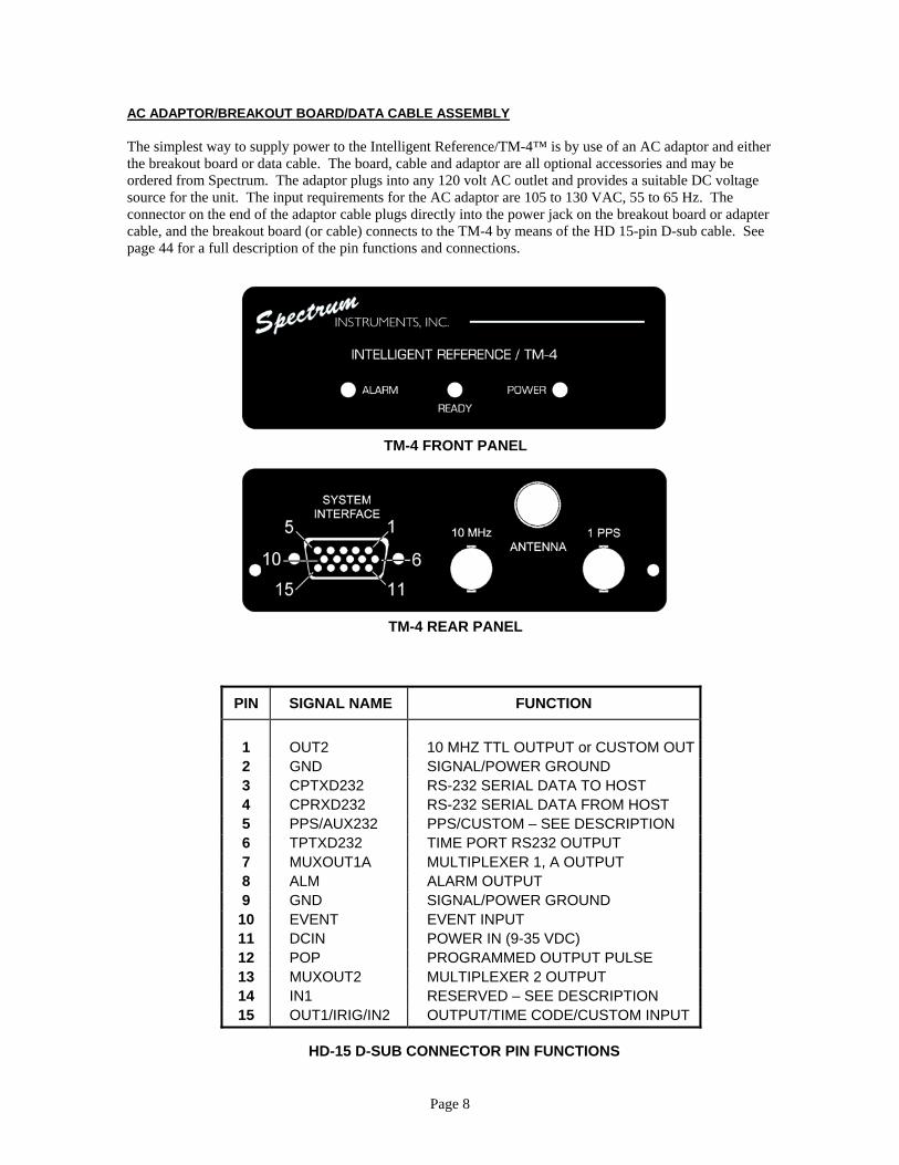
AC ADAPTOR/BREAKOUT BOARD/DATA CABLE ASSEMBLY The simplest way to supply power to the Intelligent Reference/TM-4™ is by use of an AC adaptor and either the breakout board or data cable. The board, cable and adaptor are all optional accessories and may be ordered from Spectrum. The adaptor plugs into any 120 volt AC outlet and provides a suitable DC voltage source for the unit. The input requirements for the AC adaptor are 105 to 130 VAC, 55 to 65 Hz. The connector on the end of the adaptor cable plugs directly into the power jack on the breakout board or adapter cable, and the breakout board (or cable) connects to the TM-4 by means of the HD 15-pin D-sub cable. See page 44 for a full description of the pin functions and connections.
TM-4 FRONT PANEL
TM-4 REAR PANEL
PIN SIGNAL NAME FUNCTION
1 OUT2 10 MHZ TTL OUTPUT or CUSTOM OUT 2 GND SIGNAL/POWER GROUND 3 CPTXD232 RS-232 SERIAL DATA TO HOST 4 CPRXD232 RS-232 SERIAL DATA FROM HOST 5 PPS/AUX232 PPS/CUSTOM – SEE DESCRIPTION 6 TPTXD232 TIME PORT RS232 OUTPUT 7 MUXOUT1A MULTIPLEXER 1, A OUTPUT 8 ALM ALARM OUTPUT 9 GND SIGNAL/POWER GROUND 10 EVENT EVENT INPUT 11 DCIN POWER IN (9-35 VDC) 12 POP PROGRAMMED OUTPUT PULSE 13 MUXOUT2 MULTIPLEXER 2 OUTPUT 14 IN1 RESERVED – SEE DESCRIPTION 15 OUT1/IRIG/IN2 OUTPUT/TIME CODE/CUSTOM INPUT
HD-15 D-SUB CONNECTOR PIN FUNCTIONS
Page 9
SECTION 3 - QUICK START INSTRUCTIONS The following instructions will allow the more experienced user to begin using the Intelligent Reference/TM-4™ in a minimum amount of time using a Windows®-based personal or compatible computer, the breakout board or power/data cable, AC adaptor, and the supplied control/display software. If you encounter difficulty at any point, please consult the appropriate sections of this manual for more detailed instructions and information.
1. Unpack the Intelligent Reference/TM-4™ and any accessories. 2. Set the unit near the computer and connect them together with the cables. The HD-15 D-sub cable
will connect between the TM-4 and the connector on the breakout board, and the 9-pin cable connects to the serial communications port on the computer (COM1-6) and the other connector on the breakout board. In the case of the power/data cable, the 15-pin connector will mate with the connector on the TM-4, and the 9-pin connector will mate with the serial communications port on the computer.
3. Choose an outdoor location that has a reasonably clear view of the sky, and set the antenna in an
upright position. Connect one end of the supplied antenna cable to the TNC connector on the antenna. Connect the other end to the Intelligent Reference/TM-4™ antenna connector on the rear panel.
4. Install the software. Insert the CD in the drive and open Windows Explorer. Select the drive and
click on SETUP.EXE. Follow the prompts to finish the installation. To launch the software, click on the desktop shortcut or the entry in the Start/Programs/Spectrum Control Software menu.
5. Connect the coaxial plug of the adaptor to the power connector on the breakout board (or
power/data cable) and plug the adaptor into a 120 VAC source. Move the power switch on the breakout board to the ON position. Note that Spectrum recommends that you do not connect the 15-pin connector to the unit with power already on it. The initial inrush of current can be high enough to cause an arc, and repeatedly connecting the cable to the connector in this fashion may eventually burn or damage the power input pin. Connect the cable, and then apply power. All three LEDs should rapidly flash momentarily, finishing with the POWER and ALARM LEDs illuminating steadily.
6. Start the software. If the TM-4 has been connected to a port other than COM1 on the computer, you
will need to change the communications port setting using the Set Communications Options screen available from either the menu or the toolbar.
Almost all of the information pertinent to the operation, status and control of the unit are on the main screen. You can navigate to sub screens using either the menu functions, the toolbar at the bottom, or in the case of fields where the mouse pointer changes from an arrow to a hand, by clicking on those.
Most of the functions are very simple and self-explanatory. If you need help with an item, in most
cases right-clicking on it will bring up context-sensitive help. You can also call up help with the menu or by pressing F1. In these cases the help system will start with the help file’s table of contents.
7. If you get an error message saying that the software can’t see the TM-4, check that you have
selected the correct port, that both cables are seated properly and that the TM-4 is on. Otherwise, you should now see sensible information appearing on the main screen.
Page 10
8. The unit is now searching for satellites. Observe the GPS Receiver Status panel and watch as the unit finds satellites as indicated by the SQ numbers and bar graphs being displayed. When enough satellites have been found and their ephemeris data collected, the Receiver Mode field will show Calculating Position, indicating that the unit is now navigating.
9. You should now display each of the user-selectable options and change parameters to suit your
requirements. The following list shows the choices with the factory default shown in parentheses:
• Mask Angle: (5 Degrees), 15 Degrees, or 20 Degrees. • Local Time Offset: ±Integral Hours (Default is 0). • Position Format: (Degrees and Minutes) or Degrees, Minutes and Seconds. • Altitude Units: Feet or (Meters). • User Time Bias: Bias in ±nanoseconds (Default is 0). • Timing Mode: Static or (Dynamic). • Multiplexer Outputs: Any two of several outputs. (Default is PPS Output for Mux1and Mux2). • ASCII Time Message Baud Rate: 1200, 2400, 4800, (9600), 19200, or 38400. • Communications Port: (COM1), COM2-6.
10. Once the unit is operating, calculating position and has received the offset from UTC information
(this value can take up to 12.5 minutes from the first fix to receive), the Time Valid indicator in the software will illuminate. The READY LED on the front panel will flash, the POWER LED will illuminate steadily and the ALARM LED will extinguish. When this occurs, the pulse-per-second (PPS) output becomes locked to GPS and the following functions become available:
• ASCII serial time message (Spectrum, NMEA or optional NTP) output • Programmed Output Pulse & Event Time-Tag features • Multiplexed frequency synthesizer outputs • Optional IRIG B (or other time code) serial time code generator output • Optional synthesized timing pulse output • Optional auxiliary PLL clock output
If the OCXO warm up period has expired, the unit will enter the coarse tuning mode (Mode 2) at this point and will begin to tune the OCXO. Note that if you have a TM-4 equipped with a VCXO instead of an OCXO, the unit is now ready to use. All of the above functions are active, and in this case the TM-4 will display a front panel status as described in 11 below.
11 After completion of coarse tuning, the TM-4 will enter the fine tuning (Mode 4) mode. At this
point, the main 10 MHz output (and all of its derived outputs) has reached an accuracy of better than 1 in 109 parts. The READY and POWER LEDs will illuminate continuously, indicating that the TM-4 is now in Reference Ready state. The REF READY indicator in the software will also illuminate. The Intelligent Reference/TM-4™ will now continue to fine-tune (as long as GPS remains available) to its maximum accuracy of better than 1 x 10-12.
Now that you have the TM-4 up and running, you should read the remainder of this manual to familiarize yourself with the various features, operating modes, and functions that have been designed into the unit.
Page 11
SECTION 4 - OPERATING MODES AND FUNCTIONS This section of the manual provides information on the various operating modes and functions of the Intelligent Reference/TM-4™. START-UP SEQUENCES In order for a GPS receiver to quickly find and track satellites, it needs four pieces of information:
• Date • Time • Initial Position • Almanac
Depending on which pieces of information are known to the receiver at start-up, the Intelligent Reference/TM-4™ will enter one of three start-up sequences. The amount of time required to get started, known as the time to first fix, is highly dependent on which start-up sequence is required. COLD START The worst possible situation occurs when the receiver has no information at all about date, time, user position, or satellite constellation. In this case a Cold Start is required, which involves the following steps:
1. The receiver performs a systematic search for satellites. 2. When one satellite is found, the receiver gets the time and date from that satellite and starts collecting
the current almanac. Almanac collection is a process that takes approximately 12.5 minutes. 3. While collecting the almanac, the remaining receiver channels continue to search for additional
satellites. With luck, the receiver will find two more satellites and start navigating in the two-dimensional (2D) mode while the remainder of the almanac is collected. Since the receiver does not have any knowledge of user position, finding the first position fix is a somewhat tedious process and may take a minute or two (though the time is typically under 60 seconds). This is because the receiver must perform additional calculations to rule out possible false solutions and determine which position is correct.
The entire cold start process will typically take approximately 10 minutes, but can take longer. Fortunately, you should rarely encounter the need for a cold start. The Intelligent Reference/TM-4™ is shipped with a current almanac in memory. In addition, the receiver retains the almanac and updates time and date for up to 30 days when not powered, so it should usually have time, date and almanac available at start-up. WARM START The start-up sequence most often encountered is the Warm Start, where the unit has the almanac, time, date and a reasonably accurate position that was either left over from previous operation or entered by the user. In this case, the receiver knows exactly which satellites to search for and where in frequency and the code phase to find them. It will typically find satellites in a few seconds, then spend the next 30 seconds collecting the ephemeris information for each satellite. The first fix is then produced a few seconds later. Under these conditions, the first fix is typically obtained in about 40 seconds or less.
Page 12
HOT START If the unit has been turned off for only a short time (less than about an hour), the precise ephemeris previously found for the currently visible satellites will still be valid, and start-up can take place without having to spend the 30 seconds required to collect ephemeris data. This is known as a Hot Start, and cuts the time to first fix down to about 15 seconds under typical conditions. It is important to note for all start-up modes that TTFF does not always correspond to the time it takes for Time Valid to occur. This is because in order to declare that time is valid, the offset from UTC must be known. In the GPS system, this offset value is transmitted only once every 12.5 minutes. OSCILLATOR MODES The ovenized oscillator is controlled by sophisticated algorithms in the TM-4. As the unit operates, the control of the OCXO involves several stages and processes. The various operating modes are described below:
Mode 1: Warm-up. The oven in the oscillator is being preheated to bring the OCXO to the desired operating temperature. Until this temperature is reached, the oscillator cannot be tuned or controlled. This mode can take anywhere from three to six minutes, depending on which oscillator is installed. Mode 2: Coarse tuning. The OCXO is being tuned in relatively large steps. This mode may last anywhere from a few to twenty minutes or more, depending on the initial error of the frequency when this mode began. Mode 3 Coarse tuning hold. Tuning in coarse mode is suspended due to an error condition of some sort (usually due to GPS unavailability). The tuning value is reset. Mode 4: Fine tuning. The OCXO is being tuned in very fine steps. This is the normal operating mode of the unit, and is indicated by the illumination of the READY LED. This mode always starts with the accuracy of the primary frequency better than 1x10⁻⁹, and as the unit tunes, the accuracy becomes greater and greater, approaching that of the cesium clocks on the satellites themselves. Mode 5: Fine tuning hold. Fine tuning is suspended due to an error condition of some sort (usually due to GPS unavailability). Intelligent Holdover™ takes control of the unit in this mode and provides excellent holdover characteristics. This mode is indicated by the ALARM and READY LEDs flashing, with the POWER LED remaining illuminated.
TIMING MODES Two timing modes are provided in the TM-4 for maximum accuracy and flexibility. In the Dynamic Timing Mode, the reference position for the purpose of determining precise time is the current position as determined by the GPS position solution. This mode is provided to accommodate users who require precise timing while operating on a moving platform. When operating in the Static Timing Mode, the TM-4 uses a fixed position as the reference for deriving time. In this case, the position may be user entered or previously derived from GPS. Information from all satellites tracked is used for timing, and time remains valid as long as at least one satellite is tracked. A related function is the Auto Survey mode. If you plan to operate the unit in one location, you may wish to invoke this function. Auto Survey takes the average of 10,000 position measurements and then automatically switches the unit to static timing mode. The Auto Survey function takes about 3 hours to complete.
Page 13
Once the Intelligent Reference/TM-4™ has obtained precise time from the GPS system, it declares Time Valid and enables all functions that are dependent on the availability of precise time. The Time Valid condition is indicated by a status byte in the ASCII serial time message output on the time port, by Message #64, and by combinations of front panel LEDs in various operating modes. If the unit subsequently finds that it cannot supply corrected precise time, it enters Coast Mode. Coast mode will be indicated differently, depending on what mode the TM-4 was in prior to entering the coast condition. If the unit was in Mode 2 (coarse tuning) when it entered coast, this will normally be indicated by the READY LED extinguishing, the ALARM LED flashing, and the POWER LED remaining illuminated. If the TM-4 enters coast mode while in Mode 4 (fine tuning), the POWER LED will remain illuminated, but the ALARM and READY LEDs will flash. A coast condition will also be reflected by the status byte in the ASCII serial time message. If the unit remains in the Coast Mode for 60 continuous minutes, another condition, called Coast Alarm, occurs. This condition is reflected by the ALARM and POWER LEDs illuminating and the READY LED extinguishing. This condition will also be reflected in the alarm status message (Message #65), a status byte in the serial time message, and by activation of a hardware signal on the auxiliary port connector. Note that in all coast conditions, if there is a hardware fault [antenna or 10 MHz output defective], the POWER LED will not operate as described above, but will instead flash.) The coast alarm is reset once the Time Valid condition has again been achieved. While in Coast Mode, the time and frequency outputs from the TM-4 degrade very slowly for two reasons. One is that the GPS receiver continues to supply precise time from its internal tracking loops using the loop parameters in effect when timing information was lost. The second is that the Intelligent Holdover™ function takes control of the OCXO and keeps precision high. After 3 days of locked operation, the TM-4 will degrade no more than 5 x 10-11 parts in 24 hours during a GPS outage. Shorter GPS blackouts of a few seconds or even a few minutes have will have essentially no noticeable effect on timing data. The unit returns to the Time Valid condition as soon as the GPS receiver starts supplying timing data from tracking loops that have been refreshed with new information from the GPS system. MASK ANGLE Most GPS receivers provide some control over mask angle. Mask angle is defined as the angle above the horizon below which the receiver will not try to acquire a satellite. In the Intelligent Reference/TM-4™ this is controlled by issuing a mask angle command, either with the control software or with an ASCII command. The three choices of 5 Degrees, 15 Degrees and 20 Degrees provide starting mask angles of 5, 15 and 20 degrees respectively. This sets the angle below which the receiver will not start using a satellite. If a satellite is already being used, it can drop to as low as 5 degrees in any mode before it is dropped. For most applications, we recommend a mask angle setting of 5 degrees unless the user has a specific reason to use one of the other settings. Marine users and users at fixed locations with a clear view of the sky should use 5 degrees. Choose 15 degrees for conditions where the view of the sky is mostly unobstructed. A selection of 20 degrees would be appropriate for land-mobile users in difficult terrain. MAP DATUMS Map datums are coordinate transformations that allow the user to transform the position outputs of the Intelligent Reference/TM-4™ into a coordinate system used by a particular chart or map so that positions can be plotted with accuracy. There are literally hundreds of different map datums in use around the world as different geographical areas have adopted different earth models for the purpose of creating maps. The differences in position from one datum to another can be as large as hundreds of meters. The internal representation of position in the TM-4 is referenced to the WGS84 datum. Since the TM-4 is designed as a time and frequency reference and not as a primary navigation tool, the map datum is fixed and cannot be changed. For timing applications (as opposed to positioning applications), map datum would only be
Page 14
important if you were trying to enter a fixed position for operation in the Static Timing Mode by reading that position from a map and not allowing the receiver to ever operate dynamically. In this case, Spectrum would suggest that you allow the unit to temporarily operate dynamically after entering position information, and then switch to static mode once the receiver has corrected position. For North American users, it may be helpful to know that the National Oceanic and Atmospheric Administration (NOAA) is presently converting its charts to NAD-83 which is essentially the same as WGS84. The bulk of NOAA charts now in use are referenced to NAD-27, as are most of the existing United States Geological Survey (USGS) topographic maps. USER TIME BIAS User Time Bias is a parameter that allows you to introduce a user-specified bias into all timing related functions in the TM-4. The range of bias you can enter is ±99,999 ns. Negative values cause the timing functions to occur later in absolute time while positive values cause them to occur earlier. The primary use for User Time Bias is to compensate for antenna cable length where absolute accuracy of PPS is important. Another use is to adjust the absolute timing of the unit to match other system components or standards. Changing the value of User Time Bias may introduce a perturbation in the time tracking loops that requires a few seconds to dampen out. This will manifest as a momentary dropout of the time valid status while the loops stabilize. ASCII SERIAL TIME MESSAGE/NTP/NMEA MESSAGES Once the Time Valid condition has been reached, either a standard ASCII serial time message or a subset of 0183 NMEA messages are transmitted on the TPTXD232 time port (pin 6) at the user-selected baud rate. The Spectrum standard serial time message is formatted as follows: MMDDYYYY,HHMMSS,X,YCRLF
where: MMDDYYYY is UTC date HHMMSS is UTC time X is the time valid status (0=coasting, 1=time valid) Y is the alarm status (0=off, 1=on) CRLF is a carriage return followed by a line feed
NOTE: The time broadcast in this message is the time associated with the next PPS pulse.
The default baud rate is 9600 bps, and may be changed either with the control software or by sending ASCII message #10 (see Section 6). If the unit has been configured to provide NMEA messages, the format is as follows:
$GPZDA,hhmmss.00,dd,mm,yyyy,\0,\0*csCRLF where: hhmmss.00 is UTC time
dd,mm,yyyy is UTC date \0 represents a null character (two nulls in this sentence) *cs is the "*" character and two-byte checksum CRLF is a carriage return followed by a line feed

Page 15
$GPRMC,hhmmss.00,a,ddmm.mmmm,n,dddmm.mmmm,w,zzz.zz,yyy.y,\0,\0*csCRLF where: hhmmss.00 is UTC time
a is the time valid status (A=valid, V=invalid) ddmm.mmmm is latitude in degrees and decimal minutes n is north or south (N, S) dddmm.mmmm is longitude in degrees and decimal minutes w is west or east (W, E) zzz.zz is speed over ground in knots yyy.y is course over ground in degrees \0 represents a null character (two nulls in this sentence) *cs is the "*" character and two-byte checksum CRLF is a carriage return followed by a line feed
$GPGGA,hhmmss.00,ddmm.mmmm,n,dddmm.mmmm,w,s,uu,pp.p,aaaaa.a,m,\0,\0,\0,\0*csCRLF
where: hhmmss.00 is UTC time
ddmm.mmmm is latitude in degrees and decimal minutes n is north or south (N, S) dddmm.mmmm is longitude in degrees and decimal minutes w is west or east (W, E) s is GPS status (0= fix not valid, 1= fix valid) uu is number of satellites used in navigation solution (0-12) pp.p is estimated horizontal dilution of precision (0-99.9) aaaaa.a is altitude (in meters) (0-18000) m is altitude units (always meters, M) \0 represents a null character (four nulls in this sentence) CRLF is a carriage return followed by a line feed
If the TM-4 is optionally configured to produce Network Time Protocol and NTP output is selected by the user, it appears on this output instead of the other messages. The message emulates a Type 11 device such as an Arbiter 1088A/B. The message format is 26 ASCII (24 printing) characters long, and is as follows: CRLFI YY DDD HH:MM:SS.000bbb
where: CRLF is a carriage return followed by a line feed I is the synchronization flag (blank = locked, ? = unlocked) YY is year of century DDD is day of year HH:MM:SS is hours, minutes and seconds .000 is fraction of second (not used) bbb is three trailing spaces (for message fill)
EVENT TIME-TAG (ETT) An important capability of the TM-4 is its ability to notate external events. This is called Event Time-Tag operation, or ETT. The TM-4 tags events with a resolution of 100ns. This feature is not available until the unit achieves the Time Valid condition. In this mode, the unit monitors an external event signal line looking for a logic transition. The TM-4 may be configured to look for either a positive-going or negative-going transition. When a transition is detected, the unit snapshots the date and time and stores this in its internal memory as an event time. It then continues to watch for additional events that may occur.
Page 16
Event times are passed on to the host computer over the control channel as quickly as possible. Since events may occur closely spaced in time and in bursts, the Intelligent Reference/TM-4™ buffers up to 23 event times in its memory, passing them on to the host by unloading the buffer as quickly as possible. Certain limitations on ETT operation are imposed by the design of the related hardware and software in the TM-4:
1. To ensure that an event will not be missed, the minimum latency time between any two events is 4 milliseconds.
2. The maximum continuous rate of events is 30 per second to avoid overflowing the event buffer and losing events. The buffer holds up to 23 events.
3. The pulse width of the external event signal must be greater than 10 ns to ensure that it is recognized by the hardware.
4. The input signal must be a valid TTL or CMOS logic level. PROGRAMMED OUTPUT PULSE (POP) Another important capability of the Intelligent Reference/TM-4™ is its ability to generate precisely timed pulses on an external signal line. This is called Programmed Output Pulse (POP) operation. Pulses can be programmed with a resolution of 100 ns. The TM-4 must achieve the Time Valid condition in order for this function to become available. Two operating modes are provided: POP One-Shot Mode and POP Repeat Mode. In the one-shot mode, only a single pulse is generated at the specified time and date. In the repeat mode, the time and date of the first pulse to be generated is specified exactly as in the one-shot mode. A repeat interval is also specified as an integral number of milliseconds (eight digits). After the initial pulse is generated, subsequent pulses will occur at the specified repeat interval. The output signal is a TTL/CMOS compatible pulse of user-selectable width and polarity. In POP One-Shot mode, the pulse may also be held indefinitely at a selected logic level. Note that in POP Repeat mode, the repeat interval must always be 1 (one) millisecond larger than the desired output pulse width. HARDWARE FAULT MONITORING The Intelligent Reference/TM-4™ continuously monitors the performance of critical hardware circuits and reports any abnormal operation as an alarm condition. There are three types of fault monitoring:
1. Coast Alarm - A coast alarm is reported if the unit has been in the coast condition for more than 60 minutes. This may indicate a GPS receiver or antenna failure, or that the view of the sky has become obstructed.
2. Antenna Fault - The TM-4 monitors the antenna input and reports an alarm condition if certain parameters are not correct. An antenna fault may indicate that there is no antenna connected to the unit or that there has been a failure of the GPS antenna or power supply electronics.
3. 10 MHz Frequency Output Fault - The TM-4 monitors the 10 MHz frequency output and reports an alarm condition if signal parameters are not within limits. A 10 MHz output fault may indicate that there has been a failure of the 10 MHz frequency output electronics or that the 10 MHz output level has dropped significantly below its +10 dBm nominal level.
If any of the alarm conditions occurs, the POWER LED flashes, the alarm status message (Message #65) is updated, the alarm status byte in the ASCII serial time message is updated, and the auxiliary port alarm signal (pin 8) is asserted to indicate that an alarm condition has occurred. If the alarm condition subsequently clears, these alarm indicators return to their normal condition and the TM-4 resumes normal operation.

Page 17
IRIG OR OTHER SERIAL TIME CODE OPTION The IRIG serial time code option provides the Intelligent Reference/TM-4™ with the capability to generate and output a serial time code based on the precise time obtained from GPS. IRIG B is the most commonly used of the standard serial time codes and is used to distribute precise time information to other equipment in a system or network or to time stamp data being recorded. The specifications for IRIG B and the other IRIG time codes are available from a number of sources. Other IRIG formats and other time codes are available as options. Consult the factory for details. The IRIG option provides two types of output signals: baseband and modulated carrier. On power-up, the IRIG outputs are disabled until valid time has been obtained by the GPS receiver. Once this has occurred, the outputs are continuously available, even when the unit enters the coast mode. A TM-4 with the IRIG option installed provides these functions automatically, without any need for user action. If the unit incorporates more than one time code option, the user must choose which one appears at the output by either using the control software or sending ASCII control message #16. These optional functions require that the unit has entered the Time Valid state before they become available. NETWORK TIME PROTOCOL OPTION After achieving Time Valid, a TM-4 equipped with the Network Time Protocol option will supply NTP in place of the standard serial time messages on pin 6 of the DB-15 connector, if NTP output is selected. This output emulates a Type 11 compliant device, such as the Arbiter 1088A/B. Appropriate public-domain daemons may be obtained at: http:www.eecis.udel.edu/~ntp ftp://ftp.udel.edu/pub/ntp http://www.glen-ellyn.iit.edu/~clocks/clocks/ntp/ntp.html AUXILIARY FREQUENCY OUTPUT OPTION The auxiliary frequency output option adds a phase locked loop (PLL) synthesizer to the Intelligent Reference/TM-4™ and provides a clock output that retains the accuracy and stability of the primary 10 MHz output. This signal is output on pin 1 (OUT 2) on the 15-pin D-sub connector, and virtually any common frequency is available, including widely used frequencies such as 1.544 MHz and 2.048 MHz. The stability of this output meets the MTIE requirement for a Stratum-1 primary clock source. The performance of this output in the absence of GPS signals (coasting) is excellent due to the Intelligent Holdover™ function and very high quality ovenized oscillator incorporated in the unit. This function only becomes available after the TM-4 has achieved the Time Valid condition. WIDE-RANGE FREQUENCY SYNTHESIZER OUTPUT OPTION The very wide range frequency synthesizer option allows the TM-4 to generate a factory-set frequency of the user’s choice, slaved to the primary frequency reference. This output retains the precision and quality of the primary reference and can be almost any frequency desired up, to approximately 40 MHz. The signal is output on pin 15 (OUT 1) on the 15-pin D-sub connector, and it may also be routed to the PPS connector if desired. Spectrum must be consulted with requirements prior to this feature being available in the unit.
Page 18
SYNTHESIZED TIMING PULSE OUTPUT OPTION The synthesized timing pulse output option enables the Intelligent Reference/TM-4™ to generate and output a timing pulse that is coherent with the 10 MHz clock and has the same accuracy and stability as the primary 10 MHz output. This factory-set frequency can be virtually any value up to 100 kHz, including frequencies such as 216 2/3 Hz, and the leading edges of this signal are synchronized to the average value of the PPS signal from the GPS receiver. Because of the nature of the filtering applied, these signals also have extremely low jitter. Even when SA is active (no longer considered likely), the absolute timing accuracy is enhanced by averaging out its effects. This signal is output on pin 1 (OUT 2) on the 15-pin D-sub connector. The TM-4 must have achieved Time Valid in order for this output to be enabled. ACCURACY CONSIDERATIONS There are a number of factors that can influence the accuracy of position and precise time information obtained from the Intelligent Reference/TM-4™. An appreciation of these factors will help you optimize the results obtained under various conditions. PPS OUTPUT ACCURACY The 1PPS signal at the BNC output jack is made available immediately after the TM-4 completes its initialization tasks. However, the user must take into consideration that the accuracy of this signal is not reliable until the unit has reached the Time Valid condition. Until the TM-4 reaches this state, the GPS receiver is relying upon its own internal references to generate PPS, rather than using time information derived from the GPS satellites. Do not allow critical applications to rely upon PPS until the Time Valid condition is obtained. If you have an application where PPS accuracy is critical but operation of the TM-4 cannot be monitored or verified, consider using PPS from the multiplexer outputs. Because the multiplexer outputs are disabled until the unit has Time Valid, PPS from these sources will always be accurate once they become available. GENERAL INFORMATION & POSITION ACCURACY The accuracy of position and time obtained from any GPS receiver is determined by the nature of the signal used, the characteristics of the propagation medium, the geometry of the particular situation at the time, and various hardware and software factors in the receiver itself. Using only the C/A Code signal (the more precise P Code signal is not generally available to civilian users) presents a fundamental limit on accuracy due to the resolution of range measurement implied by the spreading code rate of 1.023 MHz. This factor translates into an accuracy limit of about 15 meters in position and 50 ns in time. A sequence of measurements can be averaged to improve this accuracy somewhat. In the past, C/A Code receivers could not always achieve this accuracy due to intentional degradation of the signal by the United States Department of Defense. This degradation is called Selective Availability (SA), and its intent was to limit the accuracy available to civilian users of the system to a value much less than that which can be achieved using the C/A Code without degradation. This was achieved by intentionally introducing errors into the clock timing and the transmitted satellite ephemeris data. The past Department of Defense policy was to degrade the accuracy for C/A Code users to 100 meters (2 drms) or less under normal operating conditions. As of this writing, SA has been deactivated and is not expected to reappear in the future. The transmission medium is another source of error over which the user has no control. Receivers that utilize only one of the two transmitted carriers (L1 or L2) must rely on a mathematical model for correction of the change in path length due to ionospheric refraction (bending of the signal) as it propagates from the satellite
Page 19
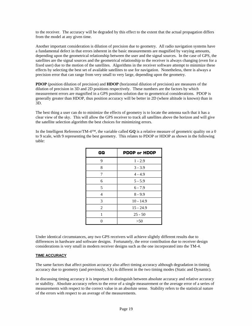
to the receiver. The accuracy will be degraded by this effect to the extent that the actual propagation differs from the model at any given time. Another important consideration is dilution of precision due to geometry. All radio navigation systems have a fundamental defect in that errors inherent in the basic measurements are magnified by varying amounts, depending upon the geometrical relationship between the user and the signal sources. In the case of GPS, the satellites are the signal sources and the geometrical relationship to the receiver is always changing (even for a fixed user) due to the motion of the satellites. Algorithms in the receiver software attempt to minimize these effects by selecting the best set of available satellites to use for navigation. Nonetheless, there is always a precision error that can range from very small to very large, depending upon the geometry. PDOP (position dilution of precision) and HDOP (horizontal dilution of precision) are measures of the dilution of precision in 3D and 2D positions respectively. These numbers are the factors by which measurement errors are magnified in a GPS position solution due to geometrical considerations. PDOP is generally greater than HDOP, thus position accuracy will be better in 2D (where altitude is known) than in 3D. The best thing a user can do to minimize the effects of geometry is to locate the antenna such that it has a clear view of the sky. This will allow the GPS receiver to track all satellites above the horizon and will give the satellite selection algorithm the best choices for minimizing errors. In the Intelligent Reference/TM-4™, the variable called GQ is a relative measure of geometric quality on a 0 to 9 scale, with 9 representing the best geometry. This relates to PDOP or HDOP as shown in the following table:
GQ PDOP or HDOP
9 1 - 2.9 8 3 - 3.9 7 4 - 4.9 6 5 - 5.9 5 6 - 7.9 4 8 - 9.9 3 10 - 14.9 2 15 - 24.9 1 25 - 50 0 >50
Under identical circumstances, any two GPS receivers will achieve slightly different results due to differences in hardware and software designs. Fortunately, the error contribution due to receiver design considerations is very small in modern receiver designs such as the one incorporated into the TM-4. TIME ACCURACY The same factors that affect position accuracy also affect timing accuracy although degradation in timing accuracy due to geometry (and previously, SA) is different in the two timing modes (Static and Dynamic). In discussing timing accuracy it is important to distinguish between absolute accuracy and relative accuracy or stability. Absolute accuracy refers to the error of a single measurement or the average error of a series of measurements with respect to the correct value in an absolute sense. Stability refers to the statistical nature of the errors with respect to an average of the measurements.
Page 20
In Dynamic Timing Mode, time is derived as one of the three or four dependent variables that are solved for in the navigation solution. Geometry, selective availability, and other factors can affect the time accuracy by approximately the same amount as they affect the position accuracy. In Static Timing Mode, the effect of geometry is eliminated because position is known. In this case, we would expect to see timing errors cut in half (no multiplier of 2 due to PDOP/HDOP). For best accuracy, users are encouraged to operate the TM-4 in static mode whenever possible. Tests of the TM-4 against a Rubidium atomic standard have verified that the quoted accuracies are achieved a large percentage of operating time. However, short term excursions from these accuracies can be expected due to a variety of causes, such as ionospheric errors and other factors. In the case of a GPS timing receiver, a specification of absolute accuracy must account for any bias in the measurements. The Intelligent Reference/TM-4™ is specified to have an absolute accuracy of ±25 ns with respect to UTC (SA off). This means that if you could measure the error of the 1 PPS output with respect to the UTC second, an average of a number of such measurements would yield a result within 25 ns of UTC. If the effect of SA were to be included, this value would be more like ±125 ns, although this cannot be definitively specified. The stability of timing measurements is specified as 12.5 ns RMS without SA in static timing mode. In summary, when operating in static mode, a large number of measurements of the time of the 1 PPS output with respect to true UTC should have a mean value within 12.5 ns of UTC and have a standard deviation of 5 ns (68% within ±5 ns of the mean). FREQUENCY ACCURACY The accuracy of the primary 10 MHz output and other outputs is dependent upon the interval over which the accuracy is measured. For longer intervals (greater than one hour), the accuracy is controlled by the oscillator discipline algorithm, which uses information derived from GPS and the built-in intelligence to accurately tune the ovenized crystal oscillator (OCXO) on frequency. In this case, the accuracy will continue to approach that of the Cesium clocks on the satellites for the length of the measurement period. For short intervals (less than an hour), the accuracy is weighted more by the inherent stability of the OCXO itself, though the tuning action is still important. The accuracy specifications given in Appendix A include these various effects. The specified accuracies are those that would be measured by an ideal frequency counter (perfect time base, infinite resolution). COASTING There are tracking loops in the GPS receiver that produce time offset and time rate (frequency) terms which are used to correct the 1 PPS signal with respect to UTC. This is a continuous process as long as the receiver is tracking satellites (static timing mode) or is calculating position fixes (dynamic timing mode). If the receiver finds that it cannot update the tracking loops, it enters coast mode and the unit signals this by dropping the Time Valid indication. The receiver continues to correct time using the loop parameters that were in place at the time coasting began. In coast mode, time will gradually drift off because these loops are not closed. The drift rate for a VCXO-equipped TM-4 will typically be 4x10⁻⁹. In the case of a standard TM-4 equipped with an OCXO, the Intelligent Holdover™ algorithm detects the loss of GPS signals and enters a frequency hold mode in which the tuning is corrected with learned and stored predictive values, significantly improving frequency and PPS accuracy during holdover. The drift rate is typically 5x10-11/day after 3 days of locked operation.
Page 21
PROGRAMMED OUTPUT PULSE & EVENT TIME-TAG The basic accuracy and stability of the Programmed Output Pulse (POP) and Event Time-Tag (ETT) functions is determined by the accuracy of timing as described earlier. The only additional consideration is that the POP function has a built-in hardware bias that may need to be considered in the most precise applications. The POP function has a bias of +150 ns– that is, output pulses will occur 150 ns late with respect to the 1 PPS signal of the unit. This can be offset by adopting a User Time Bias of +150 ns; however, this will cause the 1 PPS signal to be 150 ns early. If this effect is undesirable, another method to back POP bias out would be to subtract 150 ns from the desired POP start time when entered into the TM-4. CORRECTION FOR ANTENNA CABLE LENGTH Since not all users will use the same length of antenna cable, the PPS output from the TM-4 is not calibrated for any specific value. In cases where absolute in-time accuracy of PPS is required, the user must calculate the specific User Time Bias for his antenna cable length. In cases where Spectrum has supplied a 50-foot RG-58 cable, a User Time Bias of +77 ns is correct. For different cable lengths, an appropriate User Time Bias should be adopted. To calculate this bias, you need to know the type and length of antenna cable being used in your particular installation. Coaxial cables using polyethylene inner insulation have a delay of 1.54 ns per foot, while those with cellular poly insulation (commonly called polyfoam) have a delay of 1.30 ns per foot. To compensate for cable length, simply multiply the appropriate delay by the length of the antenna cable. The resulting number is the required User Time Bias. You can enter this value via either the control software or with a Message #06 (see Section 6) ASCII command. OPERATING SUGGESTIONS The following suggestions are offered to help the user obtain the best performance possible from the unit:
1. Mount the antenna in a good location with the best possible view of the sky. 2. Use Static Timing Mode if you are in a fixed location. 3. Leave power on the unit unless you are not going to be using it for an extended period of time.
STAND-ALONE OPERATION Once the Intelligent Reference/TM-4™ has been configured and the user options have been selected, the host computer may be disconnected at any time. The unit will continue to operate just as it did with the host connected. The only exception is if you are using the Event Time-Tag (ETT) feature. In this case, the host must be left connected to collect the event times. Otherwise, events will be lost. All important configuration information and parameters are saved in non-volatile memory so that power can be removed from the TM-4 without losing this data. When power is reapplied, the unit utilizes the parameters saved in memory to determine how it should operate. This allows the unit to be configured one time by the user and eliminates the need for the unit to be connected to a host computer. The following information is retained when power is removed from the Intelligent Reference/TM-4™:
• Almanac • UTC Time and Date
Page 22
• Last position • Mask angle selection • Timing mode selection • Time port baud rate selection • Multiplexer output selection • User Time Bias setting • Polling/Broadcast mode setting • Time Code setting • ETT operation setting • ASCII serial time message (Spectrum, NMEA or optional NTP) output setting
Note that the Programmed Output Pulse (POP) parameters are not saved. POP will continue to operate with the host computer disconnected but will not be enabled if power is removed and then reapplied. Also note that items pertaining to the GPS receiver (almanac, time, date and position) are not saved in non-volatile memory, but rather are retained by the receiver itself via a small rechargeable lithium backup battery. The useable power-off backup time of the battery is about 30 days. The Intelligent Reference/TM-4™ can be operated right out of the box without connecting it to a host computer. In this case, it will execute the cold start sequence and will operate with the factory default settings for options and configuration. MASTER RESET The Master Reset function, which is initiated by Message #08 (see Section 6), provides a complete reset of certain memory content in the Intelligent Reference/TM-4™. If you are using the Control/Display software, the Master Reset function is available in the Command Menu on the Receiver Status screen (see Section 5). When executed, the unit will initiate a cold start and adopt all factory default settings for options and configuration. This feature should seldom (if ever) be required, but is provided as a way of recovering in the event that a transient error causes the unit to operate improperly due to corrupted memory contents.
Page 23
SECTION 5 - OPERATION OF THE INTELLIGENT REFERENCE/TM-4 WITH THE CONTROL/DISPLAY SOFTWARE
This section of the manual assumes that you have performed the unpacking and installation steps outlined in Section 2 and are now ready to operate the unit using the Control/Display software. SOFTWARE OVERVIEW The Intelligent Reference/TM-4™ Control/Display software package is a control and display program which allows you to fully access the capabilities of the TM-4 without the need to develop special software for this purpose. The Control/Display software features windows, menus and dialog boxes similar to those found on many commonly available software packages. Users should have no trouble becoming familiar with the software relatively quickly. Most of the functionality of the software is accessed through the use of menus, dialog boxes and standard navigational conventions. The software will run on most Windows®-based personal computers that are equipped with a serial port available for connection to the TM-4. The software does not support versions of Windows® earlier than 95. COMPUTER REQUIREMENTS The computer requirements to operate the Intelligent Reference/TM-4™ using the Control/Display software are relatively minimal. Spectrum recommends a 233 MHz or faster Pentium-II (or higher) based machine, with at least 16-bit color. The minimally acceptable platform is a 100 MHz Pentium-based computer, with at least 256 colors. The software is supplied on a compact disc. The TM-4 connects to a standard serial port on the PC, and the baud rate for communication is fixed at 9600. The Event Time-Tag feature requires special consideration. The occurrence of an event causes only a single time-tag message to be sent to the PC. Thus, the PC must be fast enough to stay up with the message output rate if no events are to be lost. To be safe, we recommend a 233 MHz or faster machine when using the Event Time-Tag feature and dedicating the machine to that purpose while events are to be captured. INITIALIZATION FILE The program utilizes a small initialization file to save certain user options so that these options do not have to be set each time the program is started on the same computer. If no initialization file is present in the directory containing the program executable, the software sets these options to the factory default settings. Each time you change one of these settings, the initialization file is written to the application directory saving the current options. The software makes no changes to the Windows® registry except for DLL registrations. CHANGING THE COMMUNICATIONS PORT The Control/Display software defaults to COM1 if no initialization file is present. If the Intelligent Reference/TM-4™ has been connected to a different port, you’ll need to change the software to point it to the correct port. In the menu, choose Configuration/Set Communications Options and choose the appropriate port. You can also use the corresponding icon on the toolbar. The communications port setting is saved in the initialization file.
Page 24
MAIN SCREEN Almost all of the information pertinent to the operation, status and control of the Intelligent Reference/TM-4™ are on the main screen. You can navigate to sub screens using either the menu functions, the toolbar at the bottom, or in the case of fields where the mouse pointer changes from an arrow to a hand, by clicking on those. Most of the functions are very simple and self-explanatory. If you need assistance with an item on the main screen, you can call up help via the menu or by pressing F1. On sub-screens, in most cases right-clicking on the item will bring up context-sensitive help. MAIN SCREEN DETAILED DESCRIPTION The information and data that is displayed on each main display screen is relatively self-explanatory. The following sections describe the information displayed in more detail.
RECEIVER STATUS PANEL This panel reports various types of information relating to the satellite receiver and its current status. Satellite ID - This identifies which satellite is being tracked or sought by the channel. An asterisk (*) in this field indicates that the channel is currently not being utilized by the receiver. Bar Graph - This is an indication of the relative signal quality (signal to noise ratio) of the received satellite signal. SQ is measured using a 0-9 scale, with nine being the highest quality. Under most conditions, you can expect signal qualities ranging from 7-9. Lower values can occur due to the satellite being low on the horizon or partially blocked by one or more objects, or a less than ideal antenna/cable condition. An "S" in this field indicates that the receiver is currently searching for an identified satellite utilizing this channel. An "A" in this field indicates that a satellite has been found and its signal is being acquired by the receiver. The signal quality display consists of 12 bar-graph type indicators, which change both length and color depending upon signal quality. The bar indicates red for signal qualities of zero to one, yellow for conditions of greater than one and up to four, and green for SQ’s greater than four. These indicators are updated every two seconds, and thus will not show instantaneous changes in signal strength. SQ - This is a numeric indication of signal strength. An "S" in this field indicates that the receiver is currently searching for an identified satellite utilizing this channel. An "A" in this field indicates that a satellite has been found and its signal is being acquired by the receiver SQ relates to the signal to noise ratio (carrier-to-noise density ratio, or C/No) according to the following table:
SQ C/No (dB-Hz)
9 >45 8 44 7 43 6 42 5 41
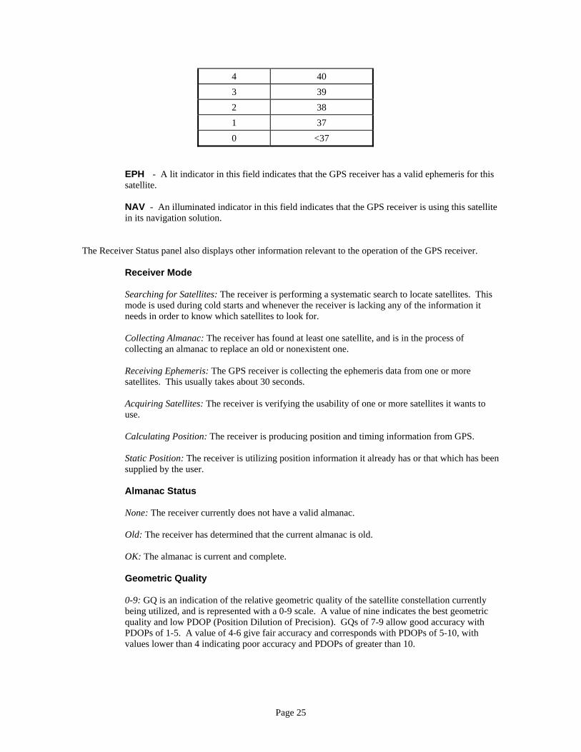
Page 25
4 40 3 39 2 38 1 37 0 <37
EPH - A lit indicator in this field indicates that the GPS receiver has a valid ephemeris for this satellite. NAV - An illuminated indicator in this field indicates that the GPS receiver is using this satellite in its navigation solution.
The Receiver Status panel also displays other information relevant to the operation of the GPS receiver.
Receiver Mode Searching for Satellites: The receiver is performing a systematic search to locate satellites. This mode is used during cold starts and whenever the receiver is lacking any of the information it needs in order to know which satellites to look for. Collecting Almanac: The receiver has found at least one satellite, and is in the process of collecting an almanac to replace an old or nonexistent one. Receiving Ephemeris: The GPS receiver is collecting the ephemeris data from one or more satellites. This usually takes about 30 seconds. Acquiring Satellites: The receiver is verifying the usability of one or more satellites it wants to use. Calculating Position: The receiver is producing position and timing information from GPS. Static Position: The receiver is utilizing position information it already has or that which has been supplied by the user. Almanac Status None: The receiver currently does not have a valid almanac. Old: The receiver has determined that the current almanac is old. OK: The almanac is current and complete. Geometric Quality 0-9: GQ is an indication of the relative geometric quality of the satellite constellation currently being utilized, and is represented with a 0-9 scale. A value of nine indicates the best geometric quality and low PDOP (Position Dilution of Precision). GQs of 7-9 allow good accuracy with PDOPs of 1-5. A value of 4-6 give fair accuracy and corresponds with PDOPs of 5-10, with values lower than 4 indicating poor accuracy and PDOPs of greater than 10.
Page 26
Mask Angle 5/10/15: Shows the current value being used by the receiver for mask angle. Satellites below the selected value will not be acquired by the receiver. If a satellite is currently being tracked, it can drop to 5 degrees before it is no longer used. You can click on this value to access the Mask Angle screen and change the mask angle setting.
TIME AND DATE PANEL
Local Time, Local Date Time/Date: This is obtained by adjusting UTC time and date by a value specified by the user in the Local Time Offset screen. Clicking on either of these fields will access this screen which also allows you to change time modes. If you select 12-hour mode, the time field shows time as AM/PM. UTC Time, UTC Date Time/Date: UTC time and date obtained from the GPS receiver.
POSITION DATA PANEL
Latitude Position: Displays the receiver's current calculated (or user input) latitude in either degrees and decimal minutes, or degrees, minutes and seconds. Clicking on this field will bring up the Set Position and Altitude screen. Longitude Position: Same as latitude. Altitude Altitude: Shows the receiver's current calculated (or input) altitude in either meters or feet. Clicking on this field will show the Set Position and Altitude screen. Satellites Used Value: Indicates the number of tracked satellites for which the receiver has obtained a valid ephemeris. Map Datum Item: Fixed at WGS84.

Page 27
TIMING STATUS PANEL Timing Mode Static: Indicates that the receiver is in static timing mode. In this mode, the receiver assumes that the values it currently has for position and altitude are correct, and derives precise time using these position coordinates. Dynamic: This mode is provided for users on a moving platform or who are starting from an unknown position. In this mode, the GPS receiver derives precise time information using the current position solution. Clicking on the field will access the Timing Mode screen which will allow you to change timing modes. Oscillator Mode 1-5: Indicates the current oscillator tuning algorithm mode. Modes are described on page 12 of this manual. User Time Bias ±99,999: Indicates the current value of user time bias in nanoseconds. Clicking on this field will access the User Time Bias screen which will allow you to set the user time bias.
ALARMS AND INDICATORS PANEL Time Valid Off: Time is not yet valid, or has become invalid. Blue: The TM-4 has obtained valid time information from GPS, and the following functions (if incorporated) have been enabled: 1PPS output, ASCII serial time message, Programmed Output Pulse, Event Time Tag, multiplexed frequency synthesizer outputs, IRIG B serial time code output, filtered timing pulse and auxiliary frequency output. Reference Ready Off: The unit has not yet achieved minimum accuracy levels. Blue: The unit has reached minimum accuracy levels of 1 x 10⁻⁹ and is in Fine Tuning (Mode 4) mode. ETT Status Off: ETT is not activated. Orange: ETT is activated, but no events have been detected. Green: ETT events have been detected. Antenna Fault Off: Antenna circuits are operating normally.

Page 28
Red: The unit has determined that the antenna circuits are not operating normally. This can be caused by an antenna that is defective or not connected, or by an antenna cable that is shorted or otherwise damaged. POP Status Off: No pulse is scheduled. Yellow: A single pulse is scheduled, but has not been generated. Orange: Multiple repeating pulses have been scheduled, but have not been generated. Green: The scheduled pulse has occurred. Red: The time to generate a scheduled pulse has passed, but the TM-4 has not achieved the Time Valid state and thus now cannot generate it. The POP function must be reinitialized with new values. 10 MHz Output Fault Off: The 10 MHz frequency output is operating normally. Red: The unit has determined that the output level of the 10 MHz frequency output is very low or absent.
The individual sub-screens are mostly self-explanatory and will not be described here. For more details, see the help file included with the application. OPERATIONAL SESSION This section of the manual walks through a typical operational session with the Intelligent Reference/TM-4™. It assumes that you have connected the unit to your PC and have made the necessary power and data connections. START-UP Apply input power to the unit. Note that Spectrum recommends that you do not connect the 15-pin connector to the unit with power already on it. The initial inrush of current can cause an arc, and repeatedly connecting the cable to the connector in this fashion may eventually burn or damage the power input pin. Connect the cable, and then apply power. At first, the three LEDs will flash, indicating that the unit is going through its initialization tasks. After initialization is complete, the POWER and ALARM LEDs will illuminate continuously. Start the control/display software. After the software initializes and the opening screen closes, you can begin to use the application. To check that the TM-4 and the host computer are communicating, look at the GPS Receiver Status Screen currently being displayed and note that there is now information being displayed in the various fields on the screen. The TM-4 is now searching for satellites. As the unit finds and tracks satellites, SQ numbers will be displayed. When enough satellites have been found and their ephemeris data collected, the Receiver Mode field will show Calculating Position, indicating that the unit is now navigating. The position will be updated every couple of seconds. When the unit is operating, calculating position and has received the UTC offset data, the ALARM LED will extinguish, indicating a normal Time Valid condition.
Page 29
When this occurs, PPS output becomes locked to GPS and the following time-related functions (if incorporated) become available:
• ASCII serial time message (Spectrum, NMEA or optional NTP) output • Programmed Output Pulse & Event Time-Tag features • Multiplexed frequency synthesizer outputs • Optional IRIG B serial time code generator outputs • Optional filtered timing pulse output • Optional auxiliary PLL clock output
SETTING OPTIONS If you have not previously done so, you should now set the user-selectable options and parameters to suit your requirements. The following list shows the choices with the factory default shown in parentheses:
• Mask Angle: (5 Degrees), 15 Degrees, or 20 Degrees. • Local Time Offset: ±Integral Hours (Default is 0). • Position Format: (Degrees and Minutes) or Degrees, Minutes and Seconds. • Altitude Units: Feet or (Meters). • User Time Bias: Bias in ±nanoseconds (Default is 0). • Timing Mode: Static or (Dynamic). • Multiplexer Outputs: Any one of available outputs. (Default is PPS). • ASCII Time Message Baud Rate: 1200, 2400, 4800, (9600), 19200 or 38400. • Communications Port: (COM1), COM2-6.
EVENT TIME-TAG OPERATION To use the Event Time-Tag feature (ETT), perform the following steps:
1. Connect the desired external signal to the EVENT signal pin (pin 10) on the 15-pin port connector. This must be a CMOS or TTL compatible signal.
2. Open the ETT sub-screen via the Command menu or by clicking on the ETT Status indicator or the toolbar icon.
3. Select the ETT mode and polarity. 4. Observe the event times displayed on the screen. This is the only sub-screen in the software that can
be minimized, rather than closed. Event times can be logged by the host computer connected to the control port. Select the Log to File option on the ETT sub-screen, and choose a filename if necessary. This filename must conform to the standard MS-DOS 8.3 format. Long filenames are not supported. The file will be located in the same folder to which the application has been installed (usually C:\TM4). In some implementations of the Intelligent Reference/TM-4™, it is not possible to use both the ETT and POP functions at the same time. If your TM-4 has simultaneous ETT/POP capability, then both functions can operate coincidentally.
Page 30
Note: there is another operation mode that disables message broadcast, and sets the unit to only output ETT and acknowledge messages. This is recommended for advanced users only. See the section on message #12 (page 34) for details. PROGRAMMED OUTPUT PULSE OPERATION To use the Programmed Output Pulse feature (POP), perform the following steps:
1. Open the POP sub-screen by clicking on the POP Status indicator, the toolbar icon or via the Command menu.
2. Enter a POP UTC date and time. This is the time that you want the first pulse to be generated. 4. If you have selected the POP Repeat Mode, enter a repeat interval (number of milliseconds between
pulses). 4. Choose output pulse polarity. 5. Choose a suitable pulse width. If you are using the POP Repeat mode, note that the repeat interval
must be at least 1 millisecond longer than the pulse width you have selected. 6. Click on OK to activate the POP feature. The pulse will be generated at the specified time and, if the
unit is set to POP Repeat Mode, at the specified intervals thereafter.
NOTE: The minimum repeat interval is 1 ms and the maximum repeat interval is 99,999,999 ms (approximately 27.78 hours).
In some implementations of the Intelligent Reference/TM-4™, it is not possible to use both the ETT and POP functions at the same time. If your TM-4 has simultaneous ETT/POP capability, it does not have this limitation. REMAINING OPERATIONS At this point, an OCXO-equipped unit should continue to tune and progress through the various operating stages. It will first enter the Mode 2 coarse tuning phase and then enter the fine tuning (Mode 4) phase. See the chart on page 43 (explaining LED combinations) for the indications that denote these modes.
Page 31
SECTION 6 - COMMUNICATING WITH THE TM-4 This section of the manual provides the information necessary to monitor and control the Intelligent Reference/TM-4™ from host computers not running the TM-4 Control/Display Software. CONTROL PORT The control port is a standard RS-232 serial channel, which accommodates a wide variety of host computers and equipment. The control port can be used to monitor and control the unit from any device using the ASCII message formats described in this section. The communication parameters are:
• 9600 baud • Eight data bits • No parity • One stop bit
Messages from the TM-4 to the host appear on pin 3 of the HD 15-pin D-sub connector. Messages to the TM-4 from the host must be applied to pin 4 of the HD 15-pin D-sub connector. COMMUNICATION MODES The Intelligent Reference/TM-4™ normally broadcasts the entire set of status messages on a repeating basis without any requests from the host computer. The control/display software is designed to utilize these messages and display the information contained within them in a meaningful fashion. There are two user-settable communication modes in which the TM-4 does not broadcast messages in the ordinary fashion. One is a modified broadcast mode in which only ETT events and the acknowledge message are supplied. The other is called polling mode, and each desired message must be requested individually by the host computer using Message #13 (Request Message Output). The TM-4 cannot be put into either of these modes via the control/display software, since the software requires a continuous stream of information in order to function. The user must set and unset these modes directly via Messages #12 and #17, either with a serial communications program or via his own application. MESSAGE FORMATS AND PROTOCOL A series of compact ASCII messages are used to control the TM-4 and to monitor its performance. The general format for messages between the host and the unit is: #NN,XXXXX,XXXX,XX,XXXXXXXX,XXXCRLF
where: NN is the message number XXXXX designates various data fields CRLF is a carriage return followed by a line feed
NOTE: Spaces are not allowed in the messages and all punctuation shown must be included.
Page 32
Unless set to polling mode, the unit acknowledges each received message with the following message: #50,1CRLF This indicates that: the message was received, the message number was legal, the line feed character was received and that the message length did not exceed the maximum message length for that message number. Message #50 is not indicative that the received message was legal or correct, only that it met the criteria listed above. Exercise caution and care when sending messages to the TM-4. It is possible to send an illegal or ill-formed message and still receive message #50. Behavior is not always consistent with an illegal message. Usually, the unit will ignore a bad message and not change corresponding modes or outgoing messages, but the POP output messages are an exception. Because they’re derived from messages sent from the host to the TM-4, they’ll be incorrectly formed if the incoming message is faulty in some fashion. If the host fails to receive the acknowledge message within a reasonable time-out interval and is expecting it, the input message should be transmitted again or some other action (such as executing an error processing routine) should be taken. Messages from the TM-4 to the host are broadcast, with no acknowledge expected or required. MESSAGES FROM THE HOST The following messages are defined for control of the Intelligent Reference/TM-4™ by a host computer. Note that in cases where input data is shorter than the required number of digits for any given message, the data must be padded with zeros. MESSAGE #05 – SET MASK ANGLE #05,XCRLF
where: X = 0 for 5 degree mask angle X = 1 for 15 degree mask angle X = 2 for 20 degree mask angle
MESSAGE #06 – SET USER TIME BIAS #06,SXXXXXCRLF
where: S = sign (+ or -) X = bias value (5 digits)
MESSAGE #07 – SET TIMING MODE #07,XCRLF
where: X = 0 for dynamic timing mode X = 1 for static timing mode X = 3 for Auto Survey mode
MESSAGE #08 – MASTER RESET #08,1CRLF
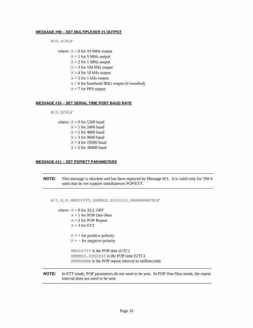
Page 33
MESSAGE #09 – SET MULTIPLEXER #1 OUTPUT #09,XCRLF
where: X = 0 for 10 MHz output X = 1 for 5 MHz output X = 2 for 1 MHz output X = 3 for 100 kHz output X = 4 for 10 kHz output X = 5 for 1 kHz output X = 6 for baseband IRIG output (if installed) X = 7 for PPS output
MESSAGE #10 – SET SERIAL TIME PORT BAUD RATE #10,XCRLF
where: X = 0 for 1200 baud X = 1 for 2400 baud X = 2 for 4800 baud X = 3 for 9600 baud X = 4 for 19200 baud X = 5 for 38400 baud
MESSAGE #11 – SET POP/ETT PARAMETERS
NOTE: This message is obsolete and has been replaced by Message #21. It is valid only for TM-4 units that do not support simultaneous POP/ETT.
#11,X,P,MMDDYYYY,HHMMSS.SSSSSSS,RRRRRRRRCRLF
where: X = 0 for ALL OFF X = 1 for POP One-Shot X = 2 for POP Repeat X = 3 for ETT P = + for positive polarity P = - for negative polarity MMDDYYYY is the POP date (UTC) HHMMSS.SSSSSSS is the POP time (UTC) RRRRRRRR is the POP repeat interval in milliseconds
NOTE: In ETT mode, POP parameters do not need to be sent. In POP One-Shot mode, the repeat interval does not need to be sent.

Page 34
MESSAGE #12 – MODIFY BROADCAST OUTPUT #12,XCRLF
where: X = 0 to output all messages X = 1 to output Event Time-Tag (Message #62) and Acknowledge (Message #50) messages only.
MESSAGE #13 – REQUEST MESSAGE OUTPUT #13,XXCRLF
where: XX = Two-digit message number for the desired message.
NOTE: This message is only enabled when the TM-4 is set to polling mode.
MESSAGE #14 – SET MULTIPLEXER #2 OUTPUT #14,XCRLF
where: X = 0 for 10 MHz output X = 1 for Mux1 mirror output X = 2 for PPS X = 3 for optional output 1 X = 4 for optional output 2 X = 5 for optional output 3 X = 6 for baseband IRIG (if installed) X = 7 for baseband NASA-36 (if installed)
MESSAGE #15 – SET SERIAL TIME MESSAGE FORMAT #15,XCRLF
where: X = 0 for standard Spectrum ASCII serial time message X = 1 for Type 11 NTP-compatible format (if installed) X = 2 for NMEA messages
MESSAGE #16 – SET MODULATED SERIAL TIME CODE FORMAT #16,XCRLF
where: X = 0 for IRIG B X = 1 for NASA-36
NOTE: This message is enabled only in units with more than one time code installed.
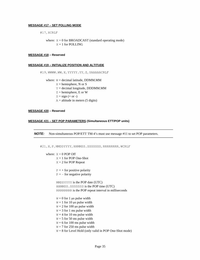
Page 35
MESSAGE #17 – SET POLLING MODE #17,XCRLF
where: X = 0 for BROADCAST (standard operating mode) X = 1 for POLLING
MESSAGE #18 – Reserved MESSAGE #19 – INITIALIZE POSITION AND ALTITUDE #19,WWWW.WW,X,YYYYY.YY,Z,SAAAAACRLF
where: W = decimal latitude, DDMM.MM X = hemisphere, N or S Y = decimal longitude, DDDMM.MM Z = hemisphere, E or W S = sign (+ or -) A = altitude in meters (5 digits)
MESSAGE #20 – Reserved MESSAGE #21 – SET POP PARAMETERS (Simultaneous ETT/POP units)
NOTE: Non-simultaneous POP/ETT TM-4’s must use message #11 to set POP parameters.
#21,X,P,MMDDYYYY,HHMMSS.SSSSSSS,RRRRRRRR,WCRLF
where: X = 0 POP Off X = 1 for POP One-Shot X = 2 for POP Repeat P = + for positive polarity P = - for negative polarity MMDDYYYY is the POP date (UTC) HHMMSS.SSSSSSS is the POP time (UTC) RRRRRRRR is the POP repeat interval in milliseconds W = 0 for 1 µs pulse width W = 1 for 10 µs pulse width W = 2 for 100 µs pulse width W = 3 for 1 ms pulse width W = 4 for 10 ms pulse width W = 5 for 50 ms pulse width W = 6 for 100 ms pulse width W = 7 for 250 ms pulse width W = 8 for Level Hold (only valid in POP One-Shot mode)
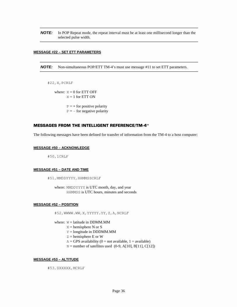
Page 36
NOTE: In POP Repeat mode, the repeat interval must be at least one millisecond longer than the selected pulse width.
MESSAGE #22 – SET ETT PARAMETERS
NOTE: Non-simultaneous POP/ETT TM-4’s must use message #11 to set ETT parameters.
#22,X,PCRLF
where: X = 0 for ETT OFF X = 1 for ETT ON P = + for positive polarity P = - for negative polarity
MESSAGES FROM THE INTELLIGENT REFERENCE/TM-4 The following messages have been defined for transfer of information from the TM-4 to a host computer: MESSAGE #50 – ACKNOWLEDGE #50,1CRLF MESSAGE #51 – DATE AND TIME #51,MMDDYYYY,HHMMSSCRLF
where: MMDDYYYY is UTC month, day, and year HHMMSS is UTC hours, minutes and seconds
MESSAGE #52 – POSITION
#52,WWWW.WW,X,YYYYY.YY,Z,A,NCRLF where: W = latitude in DDMM.MM
X = hemisphere N or S Y = longitude in DDDMM.MM Z = hemisphere E or W A = GPS availability (0 = not available, 1 = available) N = number of satellites used (0-9, A[10], B[11], C[12])
MESSAGE #53 – ALTITUDE #53,SXXXXX,MCRLF
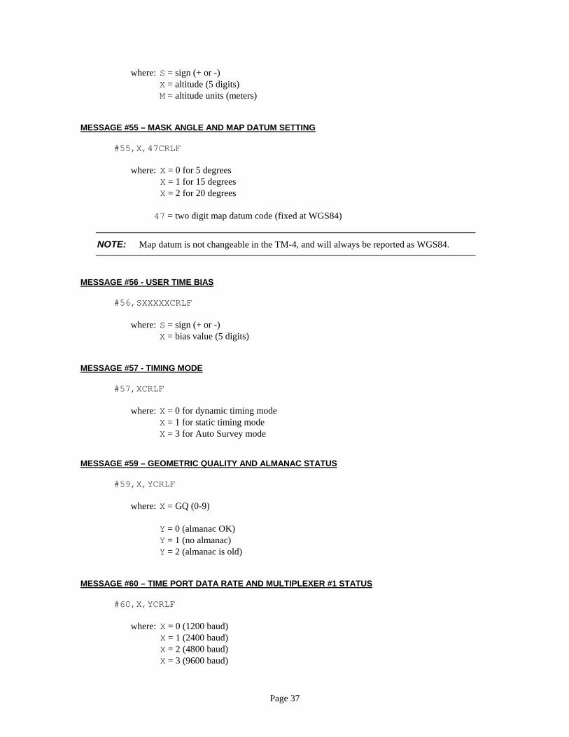
Page 37
where: S = sign (+ or -) X = altitude (5 digits) M = altitude units (meters)
MESSAGE #55 – MASK ANGLE AND MAP DATUM SETTING #55,X,47CRLF
where: X = 0 for 5 degrees X = 1 for 15 degrees X = 2 for 20 degrees
47 = two digit map datum code (fixed at WGS84)
NOTE: Map datum is not changeable in the TM-4, and will always be reported as WGS84.
MESSAGE #56 - USER TIME BIAS #56,SXXXXXCRLF
where: S = sign (+ or -) X = bias value (5 digits)
MESSAGE #57 - TIMING MODE #57,XCRLF
where: X = 0 for dynamic timing mode X = 1 for static timing mode X = 3 for Auto Survey mode
MESSAGE #59 – GEOMETRIC QUALITY AND ALMANAC STATUS #59,X,YCRLF
where: X = GQ (0-9) Y = 0 (almanac OK) Y = 1 (no almanac) Y = 2 (almanac is old)
MESSAGE #60 – TIME PORT DATA RATE AND MULTIPLEXER #1 STATUS #60,X,YCRLF
where: X = 0 (1200 baud) X = 1 (2400 baud) X = 2 (4800 baud) X = 3 (9600 baud)
Page 38
X = 4 (19200 baud) X = 5 (38400 baud) Y = 0 for 10 MHz output Y = 1 for 5 MHz output Y = 2 for 1 MHz output Y = 3 for 100 kHz output Y = 4 for 10 kHz output Y = 5 for 1 kHz output Y = 6 for IRIG output (if installed) Y = 7 for PPS output
MESSAGE #61 – TIMING STATUS #61,WCRLF
where: W = 0 (time not valid) W = 1 (time valid)
MESSAGE #62 – EVENT TIME-TAG #62,MMDDYYYY,HHMMSS.SSSSSSSCRLF
where: MMDDYYYY = UTC date of event HHMMSS.SSSSSSS = UTC time of event
MESSAGE #63 – POP/ETT STATUS
NOTE: This message is obsolete and has been replaced by Message #74. It is valid only for TM-4 units that do not support simultaneous POP/ETT.
#63,X,P,MMDDYYYY,HHMMSS.SSSSSSS,RRRRRRRRCRLF
where: X = 0 for ETT/POP OFF
X = 1 for POP One-Shot X = 2 for POP Repeat X = 3 for ETT P = + for positive polarity P = - for negative polarity P = 0 when POP/ETT mode is OFF MMDDYYYY is the POP date (UTC) HHMMSS.SSSSSSS is the POP time (UTC) RRRRRRRR is the POP repeat interval

Page 39
MESSAGE #64 – OSCILLATOR TUNING MODE #64,XCRLF
where: X = 1 for Mode 1 (oscillator warm-up) X = 2 for Mode 2 (course adjust) X = 3 for Mode 3 (course adjust standby) X = 4 for Mode 4 (fine adjust) X = 5 for Mode 5 (fine adjust hold)
MESSAGE #65 – ALARM STATUS #65,X,Y,ZCRLF
where: X = 0 (no coast condition) X = 1 (coast alarm condition) Y = 0 (antenna good) Y = 1 (antenna fault condition) Z = 0 (10 MHz frequency output good) Z = 1 (10 MHz frequency output fault condition)
MESSAGE #66 – Reserved MESSAGE #68 – MULTIPLEXER #2 STATUS #68,XCRLF
where: X = 0 for 10 MHz output X = 1 for Mux1 mirror X = 2 for PPS X = 3 for output option 1 X = 4 for output option 2 X = 5 for output option 3 X = 6 for baseband IRIG (if installed) X = 7 for baseband NASA-36 (if installed)
MESSAGE #69 – TRACKING CHANNEL STATUS #69,VV,W,X,Y,....VV,W,X,Y,ZCRLF
where: VV = PRN of satellite being tracked W = constellation status:
0 = not included in current constellation 1 = included in current constellation
X = tracking status: A = acquisition/reacquisition S = searching
Page 40
0-9 = SQ
Y = ephemeris status: 0 = not collected 1 = collected
Z = receiver status: 2 = search the sky 3 = almanac collect 4 = ephemeris collect 5 = acquisition 6 = position
NOTE: VV,W,X,Y repeats twelve times, corresponding to each of the twelve channels.
MESSAGE #70 – SERIAL TIME MESSAGE FORMAT #70,XCRLF
where: X = 0 for standard output X = 1 for NTP output (optional) X = 2 for NMEA output
MESSAGE #71 – SERIAL TIME CODE FORMAT (units with time code options) #71,XCRLF
where: X = 0 for IRIG B output X = 1 for NASA-36 output
MESSAGE #72 – Reserved MESSAGE #73 – ETT PARAMETERS (Simultaneous ETT/POP units)
#73,X,PCRLF
where: X = 0 ETT OFF X = 1 ETT ON
Page 41
MESSAGE #74 – POP PARAMETERS (Simultaneous ETT/POP units)
#74,X,P,MMDDYYYY,HHMMSS.SSSSSSS,RRRRRRRR,WCRLF
where: X = 0 for POP Off X = 1 for POP One-Shot X = 2 for POP Repeat P = + for positive polarity P = - for negative polarity MMDDYYYY is the POP date (UTC) HHMMSS.SSSSSSS is the POP time (UTC) RRRRRRRR is the POP repeat interval in milliseconds W = 0 for 1 µs pulse width W = 1 for 10 µs pulse width W = 2 for 100 µs pulse width W = 3 for 1 ms pulse width W = 4 for 10 ms pulse width W = 5 for 50 ms pulse width W = 6 for 100 ms pulse width W = 7 for 250 ms pulse width W = 8 for Level Hold
MESSAGE #75 – SPEED OVER LAND and HEADING
#75,SSS.SS,HHH.HCRLF
where: SSS.SS indicates speed over land in meters/sec HHH.H indicates course in degrees decimal
Page 42
SECTION 7 - HARDWARE INFORMATION This section of the manual provides detailed information on the Intelligent Reference/TM-4™ hardware including power specifications, input/output signal definitions and specifications, connector and pin assignments, and other miscellaneous hardware details. FRONT PANEL The front panel of the TM-4 consists of three LED indicators that provide operating and system status. These LEDs may be off, steadily illuminated, or they may flash. Important information about the unit is conveyed by various combinations of the states of these indicators. The table on the following page will also help you to understand the various combinations possible and how they relate to the current status of the unit. ALARM LED This LED indicates the general status of GPS. Under useable operating conditions, it will be off. During the initialization sequence, it will rapidly flash momentarily and then illuminate steadily while the unit acquires GPS satellites and waits for the Time Valid condition. Once time is valid, this LED will turn off. Subsequently, this LED may flash or illuminate steadily depending upon GPS condition and the mode the TM-4 was in prior to a change in conditions. If the unit was in coarse or fine tuning (Modes 2 or 4, respectively) mode and GPS is lost, this LED will flash. There is also a defined condition called Coast Alarm, in which the TM-4 has achieved Mode 4 but has lost GPS and has been in the fine tuning hold mode (Mode 5) for longer than 60 minutes. In this case, the LED will illuminate steadily. POWER LED This LED is software controlled, and its primary function is to indicate the power status of the TM-4. During the initialization sequence, it will rapidly flash momentarily and then illuminate steadily. If this indicator is off, it indicates that there is no input power being supplied to the unit or that there is some sort of microprocessor problem. When the LED is on, it indicates that the unit is operating. This LED also doubles as a hardware fault indicator. In the case of a detected hardware fault (antenna/antenna cable failure or 10 MHz output failure), this LED will change from steady illumination to a flashing state. READY LED This LED glows steadily to indicate that the TM-4 has reached a minimum acceptable accuracy level of 1 in 10–9 parts. It also is flashed to indicate certain operating cautions. During the initialization sequence, it will rapidly flash momentarily and then extinguish until the TM-4 acquires GPS. Once the unit has entered coarse tuning mode, this indicator will flash. It will extinguish if a condition arises that interrupts Mode 2 tuning and will remain off until the condition is corrected and tuning begins again, at which point it will resume flashing. Once the TM-4 enters the fine tuning mode, the LED will illuminate steadily. If the unit subsequently enters the fine tuning hold (mode 5) condition, this indicator will again flash. If the TM-4 enters Coast Alarm, the LED will turn off. See the chart on the following page for an at-a-glance explanation of TM-4 operating status.

LED COMBINATIONS AND THEIR MEANINGS
ALARM READY POWER TM-4 STATUS
rapid flash rapid flash rapid flash Start-up. The unit is completing initialization tasks. on off on/flash* Warm-up. GPS is not supplying valid time information. off off on/flash* Warm-up. GPS is supplying valid time information. off flash on/flash* Oscillator coarse tuning (Mode 2). GPS is normal.
flash off on/flash* Coarse tuning hold (Mode 3). Unit is in coast mode, due to lack of input from GPS.
off on on/flash* Oscillator fine-tuning (Mode 4). Accuracy better than 1x10⁻⁹.
GPS is normal. flash flash on/flash* Fine tuning hold (Mode 5). Unit is no longer fine-tuning due
to lack of input from GPS, but is using Intelligent Holdover™ technology to maintain oscillator accuracy. In hold mode for less than 60 minutes.
on off on/flash* Coast Alarm. Same as above, but unit has been in this condition for more than 60 minutes.
Page 43
REAR PANEL CONNECTORS AND FUNCTIONS ANTENNA CONNECTOR The antenna connector is a standard TNC jack and is the input connector for the antenna cable. 1 PPS CONNECTOR This BNC connector supplies the 1 PPS (pulse per second) output signal, which is a 1 ms (nominal) positive pulse. The driver circuit will supply TTL levels into a 50 ohm load, and the rising edge of this signal is the on-time epoch. Rise and fall times are less than 10 ns. Additionally, this connector may be reconfigured at the factory to provide modulated IRIG time code, a mirror of MUXOUT1A or some other custom output in lieu of the 1 PPS signal. The PPS signal is supplied as soon as the TM-4 finishes its initialization tasks, but is not locked to GPS until the unit achieves the Time Valid condition. 10 MHz OUT CONNECTOR This BNC connector is the disciplined 10 MHz sine wave output signal. The driver circuit will supply a level of +10 dBm nominal into a 50 ohm load. This connector may be factory reconfigured to a custom output.
* The POWER LED will indicate hardware faults in these modes by flashing. Bold indicates priority of indication.
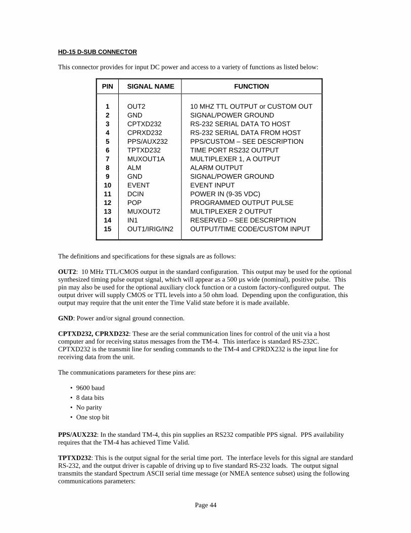
HD-15 D-SUB CONNECTOR This connector provides for input DC power and access to a variety of functions as listed below:
The definitions OUT2: 10 MHsynthesized timpin may also boutput driver woutput may req GND: Power a CPTXD232, Ccomputer and fCPTXD232 is receiving data The communic
• 9600 ba• 8 data b• No parit• One stop
PPS/AUX232:requires that th TPTXD232: TRS-232, and thtransmits the stcommunication
PIN SIGNAL NAME FUNCTION
1 OUT2 10 MHZ TTL OUTPUT or CUSTOM OUT 2 GND SIGNAL/POWER GROUND 3 CPTXD232 RS-232 SERIAL DATA TO HOST 4 CPRXD232 RS-232 SERIAL DATA FROM HOST 5 PPS/AUX232 PPS/CUSTOM – SEE DESCRIPTION 6 TPTXD232 TIME PORT RS232 OUTPUT 7 MUXOUT1A MULTIPLEXER 1, A OUTPUT 8 ALM ALARM OUTPUT 9 GND SIGNAL/POWER GROUND 10 EVENT EVENT INPUT 11 DCIN POWER IN (9-35 VDC) 12 POP PROGRAMMED OUTPUT PULSE 13 MUXOUT2 MULTIPLEXER 2 OUTPUT 14 IN1 RESERVED – SEE DESCRIPTION 15 OUT1/IRIG/IN2 OUTPUT/TIME CODE/CUSTOM INPUT
Page 44
and specifications for these signals are as follows:
z TTL/CMOS output in the standard configuration. This output may be used for the optional ing pulse output signal, which will appear as a 500 µs wide (nominal), positive pulse. This
e used for the optional auxiliary clock function or a custom factory-configured output. The ill supply CMOS or TTL levels into a 50 ohm load. Depending upon the configuration, this uire that the unit enter the Time Valid state before it is made available.
nd/or signal ground connection.
PRXD232: These are the serial communication lines for control of the unit via a host or receiving status messages from the TM-4. This interface is standard RS-232C. the transmit line for sending commands to the TM-4 and CPRDX232 is the input line for from the unit.
ations parameters for these pins are:
ud its y bit
In the standard TM-4, this pin supplies an RS232 compatible PPS signal. PPS availability e TM-4 has achieved Time Valid.
his is the output signal for the serial time port. The interface levels for this signal are standard e output driver is capable of driving up to five standard RS-232 loads. The output signal andard Spectrum ASCII serial time message (or NMEA sentence subset) using the following s parameters:
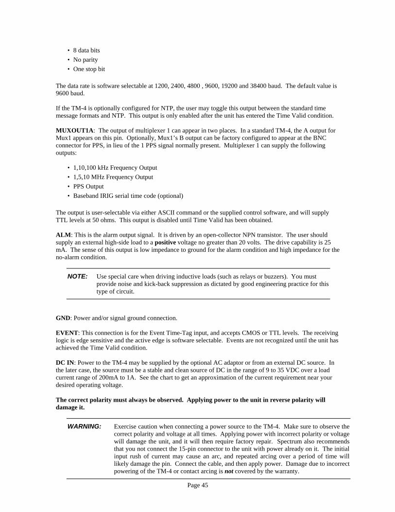
Page 45
• 8 data bits • No parity • One stop bit
The data rate is software selectable at 1200, 2400, 4800 , 9600, 19200 and 38400 baud. The default value is 9600 baud. If the TM-4 is optionally configured for NTP, the user may toggle this output between the standard time message formats and NTP. This output is only enabled after the unit has entered the Time Valid condition. MUXOUT1A: The output of multiplexer 1 can appear in two places. In a standard TM-4, the A output for Mux1 appears on this pin. Optionally, Mux1’s B output can be factory configured to appear at the BNC connector for PPS, in lieu of the 1 PPS signal normally present. Multiplexer 1 can supply the following outputs:
• 1,10,100 kHz Frequency Output • 1,5,10 MHz Frequency Output • PPS Output • Baseband IRIG serial time code (optional)
The output is user-selectable via either ASCII command or the supplied control software, and will supply TTL levels at 50 ohms. This output is disabled until Time Valid has been obtained. ALM: This is the alarm output signal. It is driven by an open-collector NPN transistor. The user should supply an external high-side load to a positive voltage no greater than 20 volts. The drive capability is 25 mA. The sense of this output is low impedance to ground for the alarm condition and high impedance for the no-alarm condition.
NOTE: Use special care when driving inductive loads (such as relays or buzzers). You must provide noise and kick-back suppression as dictated by good engineering practice for this type of circuit.
GND: Power and/or signal ground connection. EVENT: This connection is for the Event Time-Tag input, and accepts CMOS or TTL levels. The receiving logic is edge sensitive and the active edge is software selectable. Events are not recognized until the unit has achieved the Time Valid condition. DC IN: Power to the TM-4 may be supplied by the optional AC adaptor or from an external DC source. In the later case, the source must be a stable and clean source of DC in the range of 9 to 35 VDC over a load current range of 200mA to 1A. See the chart to get an approximation of the current requirement near your desired operating voltage. The correct polarity must always be observed. Applying power to the unit in reverse polarity will damage it.
WARNING: Exercise caution when connecting a power source to the TM-4. Make sure to observe the correct polarity and voltage at all times. Applying power with incorrect polarity or voltage will damage the unit, and it will then require factory repair. Spectrum also recommends that you not connect the 15-pin connector to the unit with power already on it. The initial input rush of current may cause an arc, and repeated arcing over a period of time will likely damage the pin. Connect the cable, and then apply power. Damage due to incorrect powering of the TM-4 or contact arcing is not covered by the warranty.
Page 46
There is a one-to-six minute (depending on the type of oscillator installed and its temperature at start up) period during which the unit requires more power than that normally required when operating. Note that the period of higher current consumption can be shorter than the fixed oscillator warm-up period (Mode 1 time) if the oscillator is already warm. Typical warm-up and operating currents are shown below:
INPUT VOLTAGE
WARM-UP CURRENT
OPERATING CURRENT
18 325 mA 175 mA 24 270 mA 135 mA 32 215 mA 110 mA
POP: This is the Programmed Output Pulse output signal. The polarity and pulse width of this signal is software selectable. Rise and fall times are less than 10 ns, and the output driver will supply TTL levels into a 50 ohm load. POP is disabled until the unit has reached the Time Valid condition. MUXOUT2: Multiplexer 2 can supply the following outputs:
• 10 MHz Frequency Output • Mux1 mirror • PPS • Optional outputs 1-5
The output is user-selectable via either ASCII command or the supplied control software, and will supply TTL levels at 50 ohms. This output is not available until the TM-4 has achieved Time Valid. IN1: Reserved in the standard version of the TM-4. This is an input for custom applications. OUT1/IRIG/IN2: Reserved in the standard TM-4. If the IRIG function is included, modulated time code will appear on this pin. This pin may also function as either a custom input or output. Depending upon the configuration, this output may require that the unit enter the Time Valid state before it is made available. OTHER HARDWARE CONSIDERATIONS AC ADAPTOR The optional AC adaptor requires an AC input supply voltage of 105 to 130 VAC at 55-65 Hz. Other worldwide adaptor units are available. Consult the factory for details. ANTENNA POWER The optional antenna for the TM-4 requires approximately 15 mA of current at an input voltage of 5.0 VDC. The unit supplies this voltage on the center pin of the antenna connector from a current-limited source. This power is supplied only when the unit is operating.
Page 47
SIGNAL CABLES AND TERMINATIONS The TTL outputs from the TM-4 are designed to drive 50 ohm shielded cables terminated at the end with a 50 ohm resistive load to ground. We highly recommend this practice. Other cable arrangements such as twisted pairs and non-terminated high impedance loads will work, but the user will observe ringing and distortion of the pulse shapes which are not present when using shielded cables that are properly terminated. IRIG B SERIAL TIME CODE OPTION The IRIG B serial time code option provides the Intelligent Reference/TM-4™ with the capability to generate and output a serial time code based on the precise time obtained from GPS. IRIG B is the most common of the standard serial time codes and is used to distribute precise time information to other equipment in a system or network, or to time stamp data being recorded. The specifications for IRIG B and the other IRIG time codes are available from a number of sources. IRIG B encodes the day-of-year, hours, minutes and seconds in a 100 pulse-per-second serial data stream that repeats once per second. The data is formatted as binary coded decimal (BCD) and is transmitted least significant digit first. The IRIG B serial time code option available in the TM-4 provides two types of output signals: baseband and modulated carrier. The baseband signal is IRIG B002 (pulse width coded BCD time only) and is available as one of the multiplexed output signals on the MUXOUT1A pin (7). If the PPS BNC connector has been reconfigured at the factory to output the B signal from Mux1, baseband IRIG may appear there as well. This output is TTL level, and will drive a 50 ohm load. The baseband signal consists of positive pulses (mark high, space low) with three pulse widths (2 ms = space, 5 ms = mark, 8 ms = timing pulse). The rising edge of one particular timing pulse, identified as the Reference Element, defines the one-second epoch. The encoded time data following the epoch is the time (UTC) of that epoch. The modulated carrier signal is IRIG B122, a 1000 Hz sinusoidal carrier that is amplitude modulated with the baseband signal and made available on the OUT1/IRIG/IN2 pin (15) on the HD-15 connector. This signal has a 3.3:1 modulation ratio (mark/space). It is typically able to drive a 600 ohm grounded load with a mark amplitude of 3.0 VPTP. The carrier and baseband signals are synchronous and the one-second epoch is synchronized to the positive zero crossing of a carrier cycle to within ±2 microseconds. On power-up, the IRIG outputs are disabled until valid time has been obtained by the GPS receiver. Once this has occurred, the outputs are continuously available, even when the unit enters coast mode. A TM-4 with the IRIG option installed enables these functions automatically, without any need for operator action. Note, however, that since MUXOU1A defaults to output the PPS signal unless changed, the user would need to switch its function to IRIG in order to get baseband IRIG output from it. Note that in units equipped with more than one time code function, the unit will recall the last one used whenever power is cycled. BACK-UP BATTERY AND NON-VOLATILE MEMORY Two methods are used to retain operating parameters in the Intelligent Reference/TM-4™. The GPS receiver contains a small rechargeable lithium battery which supplies a back-up voltage to retain certain critical information in memory and to allow time keeping in the total absence of input power. The TM-4 also incorporates a non-volatile backup memory device that stores various operating parameters of the unit. It is this retention of critical data and time that allows the TM-4 to have a very short time to first fix and high precision under normal conditions, after the unit has been operated and allowed to achieve Mode 4 (fine-tuning) status at least once. The retention of configuration information also allows the unit to come up from a power off condition and operate with the configuration in effect prior to removing power.

Page 48
The battery is not user-replaceable. Current is drawn from the battery only when power is not being supplied to the unit, and the battery is recharged when power is applied. A full charge from a depleted state takes approximately 24 hours of operating time. The backup time is approximately 30 days of non-operation after a full charge. If the battery is allowed to completely discharge, the GPS receiver will lose all of the information that it ordinarily stores in order to start rapidly. In this case, a cold start will take significantly longer than usual, since the receiver will have to retrieve all GPS parameters, including an almanac and UTC offset. RACK MOUNTING An optional rack-mount adapter kit is available for the Intelligent Reference/TM-4™ which allows the mounting of as many as four units in a standard 19-inch equipment rack. This adapter occupies one rack height (1U) of space. ELECTROMAGNETIC INTERFERENCE AND COMPATIBILITY The Intelligent Reference/TM-4™ radiates very little electrical noise, and should not create interference problems in most installations. It has been tested and found to comply with FCC Part 15 Class A requirements. In critical situations, consider the following precautions:
1. Always use a fully shielded cable to connect to the host computer or other controlling device. 2. Use shielded and terminated cables to connect signals from the TM-4 to other equipment. 3. Run a ground wire from the TM-4’s chassis to an earth ground point in your system, such as an AC
safety ground or ground rod. A solder lug placed under one of the connector retention nuts of the DB15 connectors on the rear panel is a good way to connect such a ground line.
4. Apply a ferrite sleeve to the AC adaptor wire at the DC plug. 5. Use a shielded cable to supply external DC power to the unit if you are not using the AC adapter. 6. Locate the unit as far away as possible from any other equipment in your system that may be
particularly sensitive to interference, particularly receivers, antenna cables and antennas. These same precautions will also be helpful in avoiding adverse effects on the operation of the TM-4 from other nearby equipment.
Page 49
SECTION 8 - IN CASE OF DIFFICULTY
NOTE: Should you have difficulty with the installation or operation of your TM-4, please take a few minutes to look through this manual. You will find the answers to most of your questions here. If you are still having difficulty after reviewing the manual, please contact us for technical support and assistance.
CONTACTING SPECTRUM If you need to contact Spectrum, please telephone or write to us at:
Spectrum Instruments, Inc. 570 East Arrow Highway Suite D San Dimas, California 91773 Phone: (909) 971-9710 E-mail: [email protected]
Before you call, please have the following information available so that we may better assist you in trying to resolve the problem immediately:
1. Model number and serial number of the unit. 2. Purchase date. 3. An accurate description of the problem.
LIMITED WARRANTY This product is warranted to be free from defects in material and workmanship for a period of one year from date of shipment. During the warranty period, Spectrum Instruments, Inc. (Spectrum) will, at its option, either repair or replace products which prove to be defective. The repaired or replaced product will be warranted for the longer of either: 1) A period of 90 days from the date of return shipment. 2) The balance of the original warranty, extended by the amount of time that the unit was out of service. To obtain repair under this warranty, the buyer must obtain a Return Authorization Number from Spectrum and return the product to a designated repair location, freight prepaid. Spectrum shall pay shipping costs to return the product to the buyer. In the case of products returned from a country other than the United States of America, the buyer shall pay all applicable duties or taxes required and freight charges both ways. EXCLUSIONS This warranty shall not apply to defects caused by abuse, neglect, accident, improper repair, alteration or modification, unreasonable use of the product by the buyer or damage in shipment to Spectrum for repair. Spectrum shall make the evaluation of the unit and shall be the sole determiner of its eligibility for or exclusion from warranty coverage.

Page 50
Software included with this product is intended but not guaranteed to run on Windows95® (or higher)-based computers, and is provided solely for the convenience of the buyer. It is supplied as-is, and is expressly excluded from any warranty. LIMITATIONS & DISCLAIMER The remedies provided by this warranty are the buyer’s sole and exclusive remedies. Spectrum shall not be liable for any direct, indirect, special, incidental, or consequential damages resulting from the buyer’s use of this product or software supplied by Spectrum. NO OTHER WARRANTY IS EXPRESSED OR IMPLIED. SPECTRUM SPECIFICALLY DISCLAIMS ANY IMPLIED WARRANTIES OF MERCHANTABILITY AND FITNESS FOR A PARTICULAR PURPOSE. It is the buyer’s sole responsibility to determine the suitability of this product for the intended use prior to purchase. Some states do not allow limitations on warranties, so some or all of the above limitations may not apply to you. RETURNING EQUIPMENT FOR REPAIR Should it become necessary for you to return equipment for repair, please take the following steps:
1. Contact us to obtain a Return Material Authorization (RMA) number. We can only accept repair returns if an RMA has been obtained.
2. Carefully pack the equipment and clearly mark the RMA number on the outside of the package. 3. Ship the package freight or postage prepaid (insurance is recommended) to the above address
unless you have been given an alternate shipping address at the time the RMA number was assigned. Be sure to include any items or accessories that we have asked to have included and any information that may be helpful in resolving the problem. Also, be sure to include your name and information on how to contact you so that we can get additional information from you if needed and let you know when the equipment has been repaired.
We will make every effort to repair your equipment and have it on its way back to you within five working days from the time it arrives at our repair facility.

Page 51
APPENDIX A - SPECIFICATIONS PHYSICAL (TM-4)
HEIGHT: 1.50 in. (38.1mm) WIDTH: 4.125 in. (104.8 mm) DEPTH: 4.50 in. (114.3 mm), excluding connectors WEIGHT: 0.75 lbs. (.34 kg)
PHYSICAL (TM-4/OEM)
HEIGHT: 1.00 in. (25.4 mm) FOOTPRINT: 4.875 in. x 3.875 in. (123.8 mm x98.4 mm) including connectors and LEDs WEIGHT: 0.25 lbs. (.11 kg)
PHYSICAL (OPTIONAL ANTENNA)
HEIGHT: 5.0 in. (126.6 mm) DIAMETER: 3.54 in. (90.0 mm) WEIGHT: 0.66 lbs. (0.30 kg) MOUNTING: Marine-thread (1.0-14UNS2A) pole mount. Optional flush and 1.25” mast mount. CABLE: RG-58 (50 ft.) with TNC connectors standard. Longer cables optional.
ENVIRONMENTAL (TM-4)
STORAGE TEMPERATURE: -40 to +85oC.
OPERATING TEMPERATURE: -20 to +70oC.
HUMIDITY: Up to 95% RH, non-condensing. ENVIRONMENTAL (OPTIONAL TIMING ANTENNA)
OPERATING TEMPERATURE: -45 to +85oC HUMIDITY: Water-resistant/All-weather.
PERFORMANCE (GPS)
RECEIVER TYPE: Twelve parallel channel, code and carrier tracking, CA code, L1 carrier. TIME TO FIRST FIX:
Hot Start: <15 seconds, typical (valid almanac, time, date, position and ephemeris) Warm Start: <40 seconds, typical (valid almanac, time, date, and position) Cold Start: <60 seconds, typical (no information)
POSITION UPDATE RATE: Once per second, nominal. MAXIMUM VELOCITY: 1000 knots (515 m/s) MAXIMUM ACCELERATION: 2 g POSITION ACCURACY: Less than 15 M SEP
PERFORMANCE (TIME)
Conditions: Time Valid. 1 PPS OUTPUT (Referenced to UTC) Accuracy: 25 ns, PTP 1 PPS TIME MESSAGE: Serial, Spectrum format ASCII date and time of next 1 PPS epoch.

Page 52
PERFORMANCE (FREQUENCY)
GPS-CORRECTED 10 MHz SINE WAVE FREQUENCY OUTPUT: Conditions: Time Valid, Tuning in Mode 4.
Long-term Stability (while tracking): 1x10-12 after 24 hours of tracking (∆t=24 hours)
Short-term Stability: 1x10-11 (∆t=1 second)
Accuracy (while coasting): <5x10-11 per day after 3 days of locked operation.
Phase Noise, 1 Hz Bandwidth: 1 Hz: <-85 dBc 10 Hz: <-115 dBc 100 Hz: <-135 dBc 1 kHz: <-145 dBc 10 kHz: <-155 dBc
Harmonic Outputs: <-50 dBc Spurious Outputs: <-70 dBc Level: +10 dBm nominal into 50 ohms
INPUTS & OUTPUTS
1 PPS OUTPUT:
CONNECTOR: BNC DRIVE: TTL levels into 50Ω PULSE WIDTH: Positive pulse, 1 ms nominal. Rising edge on-time. RISE TIME: 10 ns maximum Connector can be factory reconfigured to deliver IRIG or multiplexer output in lieu of PPS.
10 MHz OUTPUT:
CONNECTOR: BNC DRIVE: High spectral purity sine wave, +10 dBm into 50Ω, ±2dB Connector can be factory reconfigured to deliver a custom output in lieu of 10 MHz.
CONTROL AND AUXILIARY I/O: CONNECTOR: DB-15HD (female) SERIAL CONTROL I/O: RS-232C, 9600 bps, 8-N-1 ALARM OUTPUT: Open collector, 25 mA current capability. SERIAL TIME MESSAGE: RS-232C,1200-38400 bps, 8-N-1 NETWORK TIME PROTOCOL: Optional, compatible with Type 11 public-domain drivers. NMEA MESSAGES: $GPZDA, $GPRMC, $GPGGA (not all fields of all messages are provided). EXTERNAL EVENT INPUT: TTL/CMOS level, edge-triggered. Active edge is software-selectable. PROGRAMMED OUTPUT PULSE:
Drive: TTL levels into 50Ω Rise & Fall Time: 10 ns, maximum Pulse Width: 20 µsec, nominal Polarity: Selectable
MULTIPLEXER OUTPUT: Drive: TTL levels into 50Ω Rise & Fall Time: 10 ns maximum Mux1: 1 kHz, 10 kHz, 100 kHz, 1 MHz, 5 MHz, 10 MHz, PPS, optional baseband IRIG Mux2: 10 MHz, Mux1 mirror, PPS, optional custom outputs. Mux2 output pin may also be factory reconfigured for
IRIG output or as an additional input. OPTIONAL TIME CODE OUTPUT:
Type: TTL and modulated Output Level: 3.0 Vptp into 600Ω Modulation Level: 3:3.1 Time Code: IRIG B, NASA-36, other codes available

Page 53
OPTIONALWIDE-RANGE FREQUENCY SYNTHESIZER OUTPUT: Frequency: Almost any desired frequency up to 40 MHz. Factory set. Drive: TTL levels into 50Ω Accuracy: Same as for 10 MHz sine wave output. Meets Stratum-1 MTIE specifications. Rise & Fall Time: 10 ns maximum Output: 50% duty cycle
OPTIONAL AUXILARY CLOCK OUTPUT:
Frequency: Almost any standard frequency, including T1/E1. Factory set. Drive: TTL levels into 50Ω Accuracy: Same as for 10 MHz sine wave output. Meets Stratum-1 MTIE specifications. Rise & Fall Time: 10 ns maximum Output: 50% duty cycle
OPTIONAL SYNTHESIZED TIMING PULSE OUTPUT:
Frequency: Virtually any frequency up to 100 kHz, such as 1 Hz, 25 Hz, and 216.2/3 Hz. Factory set. Drive: TTL levels into 50Ω Accuracy: Same as for 10 MHz sine wave output. Meets Stratum-1 MTIE specifications. Rise & Fall Time: 10 ns maximum Characteristics: Coherent with 10 MHz output. Leading edge synchronized to average value of PPS from GPS. Extremely low jitter. Pulse Width: Positive pulse, 500 µsec nominal. Rising edge on-time.
OPTIONAL SECONDARY SINE-WAVE OUTPUT:
Frequency: Identical to, or independent of primary output frequency. Drive: High spectral purity sine wave, +10 dBm into 50Ω, ±2dB
ANTENNA INPUT: CONNECTOR: TNC
DC POWER INPUT: CONNECTOR: Pin 11 of DB-15HD CAUTION: NEVER APPLY INPUT POWER TO OTHER PINS ON THE DB-15 CONNECTOR!
POWER
INPUT SUPPLY VOLTAGE: 9 to 35 VDC WARM-UP CURRENT: 270 mA @ 24 VDC typical OPERATING CURRENT: 135 mA @ 24 VDC typical