Embed Size (px)
Citation preview
EWM HIGHTEC WELDING GmbHDr.-Günter - Henle - Straße 8; D-56271 MündersbachPhone: +49 (0)2680.181-0; Fax: +49 (0)2680.181-244Internet: www.ewm.de ; E-mail: [email protected]
Operating instructions
inverter TIG DC welding machinesfrom 150A – 300Aportable
inverter TIG 200 DC powerSinus
power Coolerinverter TIG 150 DCinverter TIG 250 DCinverter TIG 300 DC
These operating instructions must be read before commissioning!Failure to do so may be dangerous!Machines may only be operated by personnel familiar with the appropriate safety regulations!
The machines bear the conformity mark - and thus comply with the?EC Low Voltage Guideline (73/23/EEC)?EC EMV Directive (89/336/EEC)
(The CE Mark is only required in EC member states)
In compliance with VDE 0544 (EN 60974-1), the machines can be used in environments withan increased electrical hazard.
2000 We reserve the right to make amendments. Art. No.: 099-000016-EWM01 Revised: 28.08.2000
Originaldokument
liegt jedem Gerät bei!
Original document
is enclosed with each machine!
Document original
est joint à toute machine!
EG - KonformitätserklärungEU - conformity declaration
Déclaration de Conformidité de U.E.
Name des Herstellers:Name of manufacturer:Nom du fabricant:
EWM HIGHTEC WELDING GmbH(nachfolgend EWM genannt)(In the following called EWM)(nommé par la suite EWM)
Anschrift des Herstellers:Address of manufacturer:Adresse du fabricant:
Dr.- Günter - Henle - Straße 8D - 56271 Mündersbach – [email protected]
Hiermit erklären wir, daß das nachstehendbezeichnete Gerät in seiner Konzeption undBauart sowie in der von uns in Verkehr ge-brachten Ausführung den grundlegendenSicherheitsanforderungen der unten genanntenEG- Richtlinien entspricht. Im Falle vonunbefugten Veränderungen, unsachgemäßenReparaturen und / oder unerlaubten Umbauten,die nicht ausdrücklich von EWM autorisiert sind,verliert diese Erklärung ihre Gültigkeit.
We herewith declare that the machine describedbelow meets the standard safety regulations of theEU- guidelines mentionned below in its conceptionand construction, as well as in the design put intocirculation by us. In case of unauthorized changes,improper repairs and / or unauthorizedmodifications, which have not been expresslyallowed by EWM, this declaration will lose itsvalidity.
Par la présente, nous déclarons que la conceptionet la construction ainsi que le modéle, mis sur lemarché par nous, de l´appareil décrit ci - dessouscorrespondent aux directives fondamentales desécurité de la U.E. mentionnées ci- dessous. En casde changements non autorisés, de réparationsinadiquates et / ou de modifications prohibeés, quin´ont pas été autorisés expressément par EWM,cette déclaration devient caduque.
Gerätebezeichnung:Description of the machine:Déscription de la machine:
Gerätetyp:Type of machine:Type de machine:
Artikelnummer EWM:Article number:Numéro d´article
Seriennummer:Serial number:Numéro de série:
Optionen:Options:Options:
keinenoneaucune
Zutreffende EG - Richtlinien:Applicable EU - guidelines:Directives de la U.E. applicables:
EG - Niederspannungsrichtlinie (73/23/EWG)EU - low voltage guidelineDirective de la U.E. pour basses tensionsEG- EMV- Richtlinie (89/336/EWG)EU- EMC guidelineU.E.- EMC directive
Angewandte harmonisierte Normen:Used co-ordinated norms:Normes harmonisées appliquées:
EN 60974 / IEC 60974 / VDE 0544EN 50199 / VDE 0544 Teil 206
Hersteller - Unterschrift:Signature of manufacturer:Signature du fabricant:
Michael Szczesny , Geschäftsführermanaging directorgérant
05.2000
Table of Content Page
Inhalt/1
Safety instructions................................................................................................................................Safety/1
For your safety ................................................................................................................................. Safety/1
Transportation and set up ....................................................................................................................... Safety/3
Notes on the use of these operating instructions .................................................................................... Safety/3
General ........................................................................................................................................AI/1
About this machine manufactured in inverter technology...............................................................................AI/1
The advantages of inverter technology: .........................................................................................................AI/1
1 Technical data ..................................................................................................................................... 1/1
1.1 Area of application ...................................................................................................................... 1/1
2 Operating elements ............................................................................................................................ 2/1
3 Function specification logic control ................................................................................................. 3/1
3.1 Logic control ............................................................................................................................... 3/1
3.2 Function sequence of TIG non-latched operation without UP/DOWN-SLOPE........................... 3/5
3.3 Function sequence of TIG non-latched operation with UP/DOWN-SLOPE................................ 3/6
3.4 Function sequence of TIG latched operation with UP/DOWN-SLOPE....................................... 3/7
3.5 MMA welding .............................................................................................................................. 3/8
3.6 Remote controls........................................................................................................................ 3/10
3.7 Interface for mechanised welding (remote control connection socket) ..................................... 3/12
4 Quick start – the shortest way to welding........................................................................................ 4/1
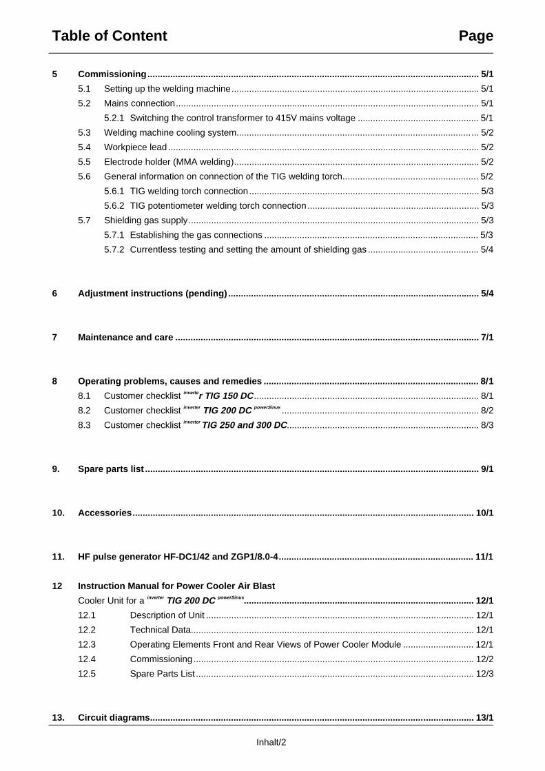
Table of Content Page
Inhalt/2
5 Commissioning................................................................................................................................... 5/1
5.1 Setting up the welding machine.................................................................................................. 5/1
5.2 Mains connection........................................................................................................................ 5/1
5.2.1 Switching the control transformer to 415V mains voltage ................................................ 5/1
5.3 Welding machine cooling system................................................................................................ 5/2
5.4 Workpiece lead ........................................................................................................................... 5/2
5.5 Electrode holder (MMA welding)................................................................................................. 5/2
5.6 General information on connection of the TIG welding torch...................................................... 5/2
5.6.1 TIG welding torch connection........................................................................................... 5/3
5.6.2 TIG potentiometer welding torch connection.................................................................... 5/3
5.7 Shielding gas supply................................................................................................................... 5/3
5.7.1 Establishing the gas connections ..................................................................................... 5/3
5.7.2 Currentless testing and setting the amount of shielding gas ............................................ 5/4
6 Adjustment instructions (pending) ................................................................................................... 5/4
7 Maintenance and care ........................................................................................................................ 7/1
8 Operating problems, causes and remedies ..................................................................................... 8/1
8.1 Customer checklist inverter TIG 150 DC ......................................................................................... 8/1
8.2 Customer checklist inverter TIG 200 DC powerSinus .............................................................................. 8/2
8.3 Customer checklist inverter TIG 250 and 300 DC............................................................................ 8/3
9. Spare parts list .................................................................................................................................... 9/1
10. Accessories....................................................................................................................................... 10/1
11. HF pulse generator HF-DC1/42 and ZGP1/8.0-4............................................................................. 11/1
12 Instruction Manual for Power Cooler Air Blast
Cooler Unit for a inverter TIG 200 DC powerSinus........................................................................................... 12/1
12.1 Description of Unit .......................................................................................................... 12/1
12.2 Technical Data................................................................................................................ 12/1
12.3 Operating Elements Front and Rear Views of Power Cooler Module ............................ 12/1
12.4 Commissioning ............................................................................................................... 12/2
12.5 Spare Parts List .............................................................................................................. 12/3
13. Circuit diagrams................................................................................................................................ 13/1
Safety instructions
Safety /1
For Your Safety:Warning: Observe accident prevention regulations.Ignoring the following safety procedures can be fatal.
• Before undertaking welding tasks, put on prescribed dry protective clothing, e.g. gloves.
• Protect eyes and face with protective visor.
Electric shocks can be fatal
• The machine may only be connected to correctly earthed sockets.
• Only operate with intact connection lead including protective conductor and safety plug.
• An improperly repaired plug or damaged mains cable insulation can cause electric shocks.
• The machine may only be opened by qualified and authorised personnel.
• Before opening, pull out the mains plug. Switching off is not sufficient. Wait for 2 minutesuntil capacitors are discharged.
• Always put down welding torch, stick electrode holder in an insulated condition.
Even touching low voltages can cause you to jump and lead to accidents, so:
• Safeguard yourself against falls, e.g. from a platform or scaffolding.
• When welding, operate earth tongs, torch and workpiece properly, not in ways for which theyare not intended. Do not touch live parts with bare skin.
• Only replace electrodes when wearing dry gloves.
• Never use torches or earth cables with damaged insulation.
Smoke and gases can lead to breathing difficulties and poisoning.
• Do not breathe in smoke and gases.
• Ensure that there is sufficient fresh air.
• Keep solvent vapours away from the arc radiation area. Chlorinated hydrocarbon fumes canbe converted into poisonous phosgene by ultraviolet radiation.
Workpiece, flying sparks and droplets are hot
• Keep children and animals well away from the working area. Their behaviour is unpredictable.
• Move containers with inflammable or exposive liquids away from the working area.There is a danger of fire and explosion.
• Never heat explosive liquids, dusts or gases by welding or cutting. There is also a danger ofexplosion if apparently harmless substances in closed containers are able to build up excesspressure when they are heated.
Take care to avoid fire hazards
• Any kind of fire hazards must be avoided. Flames can form e.g. when sparks are flying, whenparts are glowing or hot slag is present.
• A constant check must be kept on whether fire hazards have been created in the working area.
• Highly inflammable objects, such as matches and cigarette lighters for example, must not becarried in trouser pockets.
• You must ensure that fire extinguishing equipment - appropriate to the welding process - isavailable close to the welding work area and that easy access is possible.
Safety instructions
Safety /2
Take care to avoid fire hazards
• Containers in which fuels or lubricants have been present must be thoroughly cleaned beforewelding begins. It is not sufficient simply for the receptacle to be empty.
• After a workpiece has been welded, it must only be touched or brought into contact withinflammable material when it has cooled down sufficiently.
• Loose welding connections can completely destroy protective conductor systems of interiorinstallations and cause fires. Before beginning welding work, ensure that the earth tongs areproperly fixed to the workpiece or welding bench and that there is a direct electrical connectionfrom the workpiece to the power source.
Noise exceeding 70 dBA can cause permanent hearing damage
• Wear suitable earmuffs or plugs.
• Ensure that other people who spend time in the working area are not inconvenienced by thenoise.
Secure gas cylinder
• Place shielding gas cylinders in the holders provided for them and secure with safety chains.
• Take care when handling cylinders; do not throw or heat, guard against them toppling over.
• When moving by crane, take off the gas cylinder from the welding machine.
Caution: Interference by electrical and electromagnetic fields is possible e.g. from thewelding machine or from the high-voltage pulses of the ignition unit.
• As laid down in Electromagnetic Compatibility Standard EN 50199, the machines are intendedfor use in industrial areas; if they are operated e.g. in residential environments problems canoccur in ensuring electromagnetic compatibility.
• The functioning of heart pacemakers can be adversely affected when you are standing nearthe welding machine.
• Malfunctioning of electronic equipment (e.g. EDP, CNC equipment) in the vicinity of thewelding location is possible.
• Other mains supply leads, trip leads, signal and telecommunications leads above, under andnear the welding device may be subject to interference.
Warning: Electromagnetic interference must be reduced to such a level that it no longerconstitutes interference.Possible reduction measures:
• Welding machines should be regularly maintained (see Sect. “Maintenance and care”)
• Welding leads should be as short as possible and run closely together on or near to theground.
• Selective shielding of other leads and equipment in the environment can reduce radiation.
Caution: Repairs and modifications may only be carried out by authorised, trained,specialist personnel.The warranty becomes null and void in the event of unauthorised interference.
Our operating instructions will provide you with an introduction into the safe use of themachine.Therefore please read them closely and only start work when you are familiar with them.
Safety instructions
Safety /3
Transport and set-up• Machines may only be moved and operated in an upright position.
• Before moving, pull out mains plug and place on the machine.
• Secure high-pressure shielding gas cylinder with safety chain to prevent it from toppling
over.
Environmental conditions: The welding machine can be operated in a location where there is no risk of explosion at
• an ambient temperature of -10°C (plasma machines 0°C) to +40°C and
• a relative air humidity up to 50% at 40°C.
• where the surrounding air is free of unusual amounts of dust, acids, corrosive gases orsubstances etc., insofar as they do not occur during welding.Examples of unusual operating conditions:Unusual corrosive smoke, vapour, excessive oil vapour, unusual vibrations or jolts, excessivequantities of dust such as grinding dust etc., severe weather conditions, unusual conditions nearthe coast or on board ship.
• When setting up the machine, ensure that air inlets and outlets are unobstructed.The machine is tested to Protection Standard IP23, i.e.:
• Protection against penetration of solid foreign bodies ∅ > 12mm,
• Protection against water spray up to an angle of 60° to the vertical.
Notes on the use of these operating instructions These operating instructions are arranged in Sections. To help you find your way around more quickly, in the margins you will occasionally see, in additionto sub-headings, icons referring to particularly important passages of text which are graded asfollows depending on their importance:
(Note): Applies to special technical characteristics which the user must note.
(Warning): Applies to working and operating procedures which must be followed
precisely to avoid damaging or destroying the machine.
(Caution): Applies to working and operating procedures which must be followed
precisely to avoid endangering people and includes the “Warning” symbol.
Instructions and lists detailing step-by-step actions in given situations can be recognisedby bullet points, e.g.:• Insert plug of welding current lead into socket (Sect. 5, G2) and lock.
Meaning of the diagram descriptions:e.g. (C1) means: Item C / Figure 1 in the respective Sectione.g. (Sect. 3, C1) means: in Section 3 Item C / Figure 1
General
AL/1
About this machine manufactured in inverter technologyCongratulations.
You have purchased a modern and efficient welding machine in inverter technology.
In contrast to conventional power sources, it does not operate with 50Hz but with a 25kHz primary
driven transistor current source.
The advantages of inverter technology:
• Less effort in changing to another workplace because the machine dimensions and weight are
substantially reduced.
• Lower power consumption and smaller mains ratings by high efficiency (no losses).
• No need for expensive compensating equipment by a high cos phi and a correspondingly
smaller reactive current draw from the mains.
• Functional safety by robust construction, highly integrated electronic circuitry.
• High operating safety by thermal monitors in the power circuit.
• High control dynamics for the welding process. Therefore excellent welding and ignition results
and absolute reproducibility of all welding parameters.
• Welding result independent of mains voltage fluctuations.
• Easily serviced design by the use of modern, modular technology.
The powerSinus – Series:
The machines with powerSinus series have a built-in electronic switching unit which restricts the
current spikes coming from the mains supply and produces a pure Sinus-form of mains current. As
a result 200Amps welding current can be achieved from a 230V plug fused at 16Amps with
a cos phi of 1.
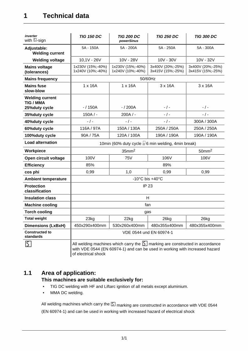
1 Technical data
1/1
inverterwith S -sign
TIG 150 DC TIG 200 DCpowerSinus
TIG 250 DC TIG 300 DC
Adjustable:Welding current
5A - 150A 5A - 200A 5A - 250A 5A - 300A
Welding voltage 10,1V - 26V 10V - 28V 10V - 30V 10V - 32V
Mains voltage(tolerances)
1x230V (15%;-40%)1x240V (10%;-40%)
1x230V (15%;-40%)1x240V (10%;-40%)
3x400V (20%;-25%)3x415V (15%;-25%)
3x400V (20%;-25%)3x415V (15%;-25%)
Mains frequency 50/60Hz
Mains fuseslow-blow
1 x 16A 1 x 16A 3 x 16A 3 x 16A
Welding currentTIG / MMA25%duty cycle - / 150A - / 200A - / - - / -
35%duty cycle 150A / - 200A / - - / - - / -
40%duty cycle - / - - / - - / - 300A / 300A
60%duty cycle 116A / 97A 150A / 130A 250A / 250A 250A / 250A
100%duty cycle 90A / 75A 120A / 100A 190A / 190A 190A / 190A
Load alternation 10min (60% duty cycle ∧ 6 min welding, 4min break)
Workpiece 35mm2 50mm2
Open circuit voltage 100V 75V 106V 106V
Efficiency 85% 89%
cos phi 0,99 1,0 0,99 0,99
Ambient temperature -10°C bis +40°C
Protectionclassification
IP 23
Insulation class H
Machine cooling fan
Torch cooling gas
Total weight 23kg 22kg 26kg 26kg
Dimensions (LxBxH) 450x290x400mm 530x260x400mm 480x355x400mm 480x355x400mm
Constructed tostandards
VDE 0544 und EN 60974-1
S All welding machines which carry the S marking are constructed in accordancewith VDE 0544 (EN 60974-1) and can be used in working with increased hazardof electrical shock
1.1 Area of application:This machines are suitable exclusively for:• TIG DC welding with HF and Liftarc ignition of all metals except aluminium.
• MMA DC welding.
All welding machines which carry the S marking are constructed in accordance with VDE 0544
(EN 60974-1) and can be used in working with increased hazard of electrical shock
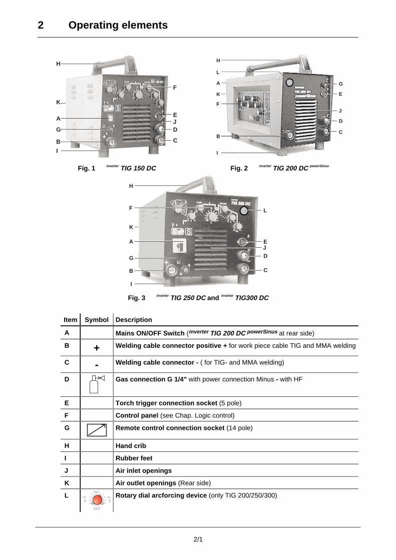
2 Operating elements
2/1
F
E
DJ
C
H
A
G
B
I
K
H
A
L
K
F
B
I
G
E
D
J
C
Fig. 1 inverter TIG 150 DC Fig. 2 inverter TIG 200 DC powerSinus
H
F
A
K
B
G
I
E
L
D
C
J
Fig. 3 inverter TIG 250 DC and inverter
TIG300 DC
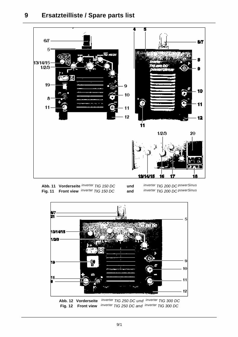
Item Symbol Description
A Mains ON/OFF Switch (inverter TIG 200 DC powerSinus at rear side)
B + Welding cable connector positive + for work piece cable TIG and MMA welding
C - Welding cable connector - ( for TIG- and MMA welding)
D Gas connection G 1/4" with power connection Minus - with HF
E Torch trigger connection socket (5 pole)
F Control panel (see Chap. Logic control)
G Remote control connection socket (14 pole)
H Hand crib
I Rubber feet
J Air inlet openings
K Air outlet openings (Rear side)
L 91
0
ArcForce
10
RUTIL
3
2 CELL
BASISCH
7
8 Rotary dial arcforcing device (only TIG 200/250/300)
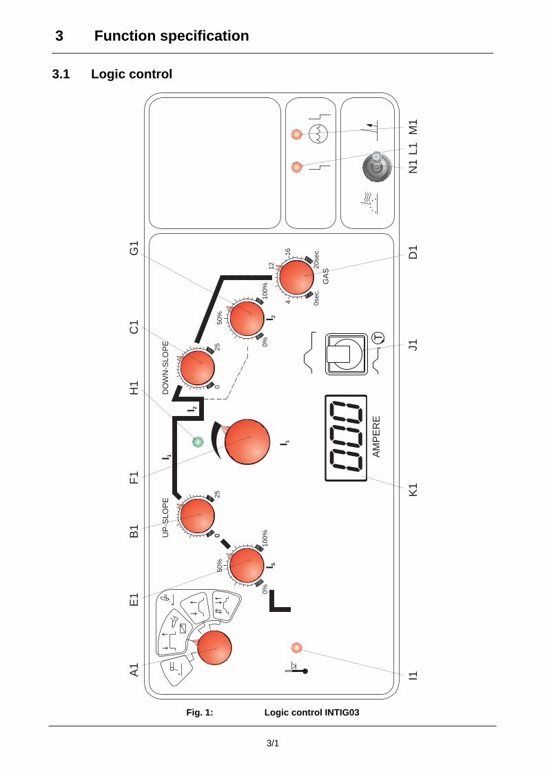
3 Function specification
3/1
3.1 Logic control
0%
0025
250
100%
100%
0%
0sec
.
4
12
16
20se
c.
50%
I SI 2
I 1
GA
S
AM
PE
RE
I 1
I 2
UP
-SLO
PE
DO
WN
-SLO
PE
50%
T
000
A1
F1
E1
B1
H1
C1
G1
I1K
1J1
D1
L1N
1M
1
Fig. 1: Logic control INTIG03
3 Function specification
3/2
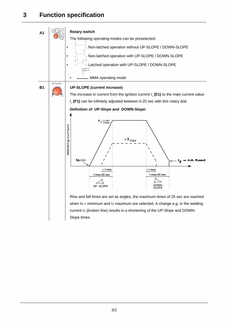
A1 Rotary switch
The following operating modes can be preselected:
• Non-latched operation without UP-SLOPE / DOWN-SLOPE
• Non-latched operation with UP-SLOPE / DOWN-SLOPE
• Latched operation with UP-SLOPE / DOWN-SLOPE
• MMA operating mode
B1
00 25
UP-SLOPE
UP-SLOPE (current increase)
The increase in current from the ignition current Is (E1) to the main current value
I1 (F1) can be infinitely adjusted between 0-25 sec with this rotary dial.
Definition of UP-Slope and DOWN-Slope:
Rise and fall times are set as angles, the maximum times of 25 sec are reached
when Is = minimum and I1 maximum are selected. A change e.g. in the welding
current I1 (broken line) results in a shortening of the UP-Slope and DOWN-
Slope times.
3 Function specification
3/3
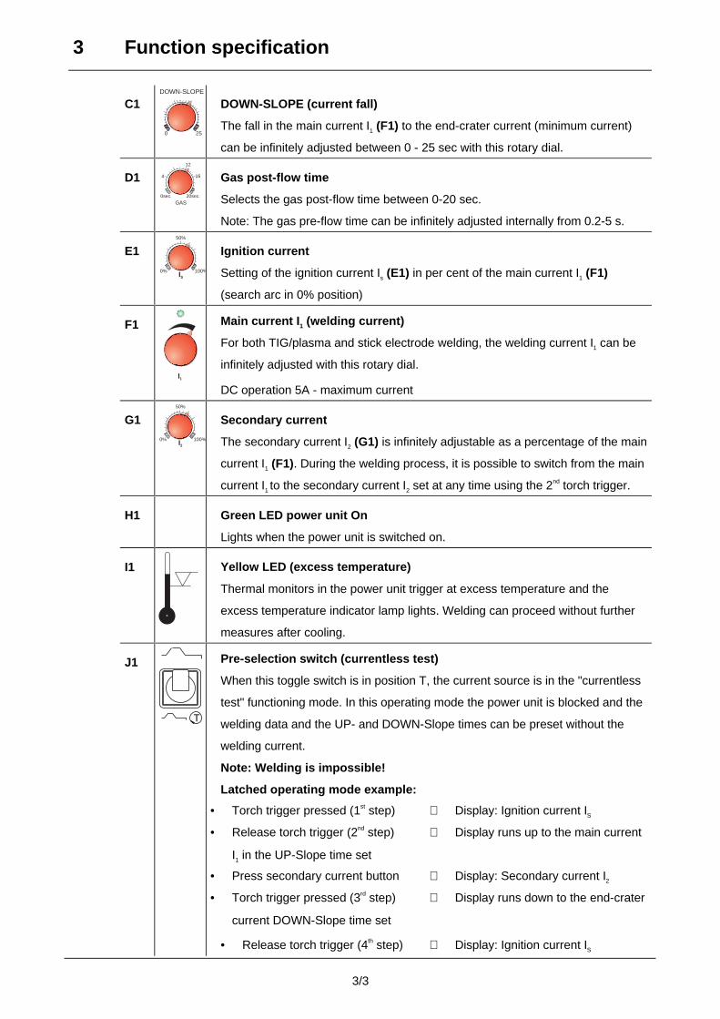
C1
250
DOWN-SLOPE
DOWN-SLOPE (current fall)
The fall in the main current I1 (F1) to the end-crater current (minimum current)
can be infinitely adjusted between 0 - 25 sec with this rotary dial.
D10sec.
4
12
16
20sec.
GAS
Gas post-flow time
Selects the gas post-flow time between 0-20 sec.
Note: The gas pre-flow time can be infinitely adjusted internally from 0.2-5 s.
E10% 100%IS
50%
Ignition current
Setting of the ignition current Is (E1) in per cent of the main current I1 (F1)
(search arc in 0% position)
F1
I1
Main current I1 (welding current)
For both TIG/plasma and stick electrode welding, the welding current I1 can be
infinitely adjusted with this rotary dial.
DC operation 5A - maximum current
G1100%0%
50%
I2
Secondary current
The secondary current I2 (G1) is infinitely adjustable as a percentage of the main
current I1 (F1). During the welding process, it is possible to switch from the main
current I1 to the secondary current I2 set at any time using the 2nd torch trigger.
H1 Green LED power unit On
Lights when the power unit is switched on.
I1 Yellow LED (excess temperature)
Thermal monitors in the power unit trigger at excess temperature and the
excess temperature indicator lamp lights. Welding can proceed without further
measures after cooling.
J1
T
Pre-selection switch (currentless test)
When this toggle switch is in position T, the current source is in the "currentless
test" functioning mode. In this operating mode the power unit is blocked and the
welding data and the UP- and DOWN-Slope times can be preset without the
welding current.
Note: Welding is impossible!
Latched operating mode example:
• Torch trigger pressed (1st step) ⇒ Display: Ignition current IS
• Release torch trigger (2nd step) ⇒ Display runs up to the main current
I1 in the UP-Slope time set
• Press secondary current button ⇒ Display: Secondary current I2
• Torch trigger pressed (3rd step) ⇒ Display runs down to the end-crater
current DOWN-Slope time set
• Release torch trigger (4th step) ⇒ Display: Ignition current IS
3 Function specification
3/4
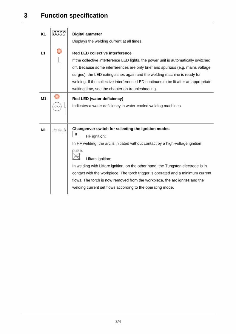
K1 0000 Digital ammeter
Displays the welding current at all times.
L1 Red LED collective interference
If the collective interference LED lights, the power unit is automatically switched
off. Because some interferences are only brief and spurious (e.g. mains voltage
surges), the LED extinguishes again and the welding machine is ready for
welding. If the collective interference LED continues to be lit after an appropriate
waiting time, see the chapter on troubleshooting.
M1 Red LED (water deficiency)
Indicates a water deficiency in water-cooled welding machines.
N1 Changeover switch for selecting the ignition modesHF HF ignition:
In HF welding, the arc is initiated without contact by a high-voltage ignition
pulse.
HFLiftarc ignition:
In welding with Liftarc ignition, on the other hand, the Tungsten electrode is in
contact with the workpiece. The torch trigger is operated and a minimum current
flows. The torch is now removed from the workpiece, the arc ignites and the
welding current set flows according to the operating mode.
3 Function specification
3/5
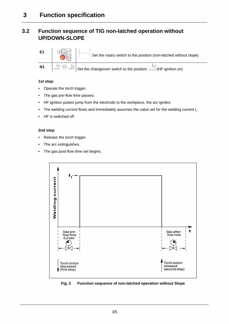
3.2 Function sequence of TIG non-latched operation withoutUP/DOWN-SLOPE
E1Set the rotary switch to the position (non-latched without slope)
N1 Set the changeover switch to the position (HF ignition on)
1st step:
• Operate the torch trigger.
• The gas pre-flow time passes.
• HF ignition pulses jump from the electrode to the workpiece, the arc ignites.
• The welding current flows and immediately assumes the value set for the welding current I1.
• HF is switched off.
2nd step:
• Release the torch trigger.
• The arc extinguishes.
• The gas post-flow time set begins.
Fig. 2 Function sequence of non-latched operation without Slope
3 Function specification
3/6
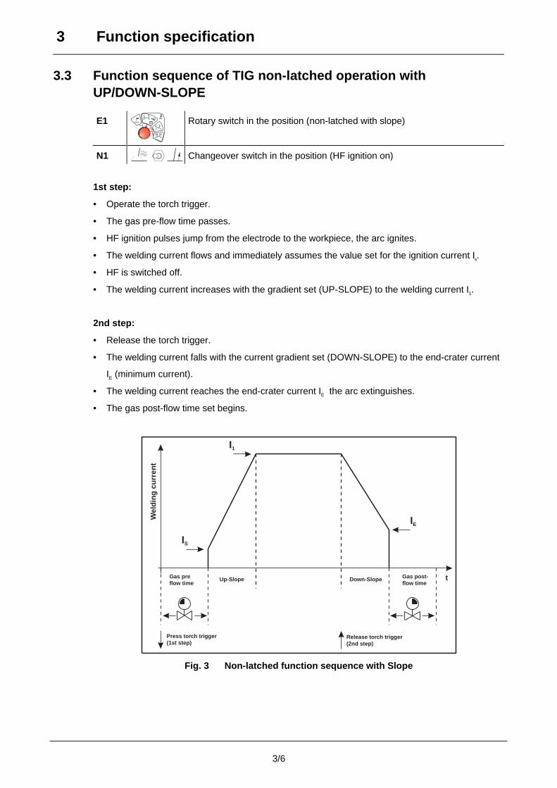
3.3 Function sequence of TIG non-latched operation withUP/DOWN-SLOPE
E1 Rotary switch in the position (non-latched with slope)
N1 Changeover switch in the position (HF ignition on)
1st step:
• Operate the torch trigger.
• The gas pre-flow time passes.
• HF ignition pulses jump from the electrode to the workpiece, the arc ignites.
• The welding current flows and immediately assumes the value set for the ignition current Is.
• HF is switched off.
• The welding current increases with the gradient set (UP-SLOPE) to the welding current I1.
2nd step:
• Release the torch trigger.
• The welding current falls with the current gradient set (DOWN-SLOPE) to the end-crater current
IE (minimum current).
• The welding current reaches the end-crater current IE the arc extinguishes.
• The gas post-flow time set begins.
IS
I1
IE
Down-SlopeUp-Slope t
Release torch trigger(2nd step)
Wel
ding
cur
rent
Gas preflow time
Press torch trigger(1st step)
Gas post-flow time
Fig. 3 Non-latched function sequence with Slope
3 Function specification
3/7
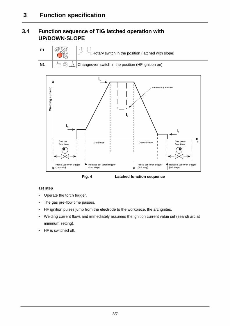
3.4 Function sequence of TIG latched operation withUP/DOWN-SLOPE
E1Rotary switch in the position (latched with slope)
N1 Changeover switch in the position (HF ignition on)
IS
I1
I2
IE
Down-SlopeUp-Slope t
Wel
ding
cur
rent
Gas preflow time
Gas post-flow time
secondary current
Press 1st torch trigger(1st step)
Release 1st torch trigger(2nd step)
Press 1st torch trigger(3rd step)
Release 1st torch trigger(4th step)
Fig. 4 Latched function sequence
1st step
• Operate the torch trigger.
• The gas pre-flow time passes.
• HF ignition pulses jump from the electrode to the workpiece, the arc ignites.
• Welding current flows and immediately assumes the ignition current value set (search arc at
minimum setting).
• HF is switched off.
3 Function specification
3/8
2nd step
• Release the torch trigger.
• The welding current increases with the gradient set (UP-SLOPE) to the welding current I1.
With the second torch trigger, it is possible to switch to the secondary current operating
point I2 during welding.
3rd step
• Operate the torch trigger.
• The welding current falls with the gradient set (DOWN-SLOPE) to the end-crater current IE
(minimum current).
4th step
• Release the torch trigger.
• The arc extinguishes.
• The gas post-flow time set begins.
It is also possible to terminate the welding procedure immediately without DOWN-SLOPE and
end-crater current By briefly operating the 1st torch trigger (3rd step). The current falls to zero
and the gas post-flow time begins.
Automatic cut-out:
In latched operating mode, if no ignition of the arc occurs after operation and release of the
torch trigger or if the arc is interrupted when the torch is moved away, an automatic cut-out
occurs within 3 sec.
The HF, gas and open circuit voltage (power unit) are switched off.
3.5 MMA welding
E1Rotary switch in the position (electrode)
F1
I1
Select welding current I1 (5A - maximum current).
If welding is performed alternately by different methods, e.g. TIG or MMA, and if a welding
torch and an electrode holder are connected to the machine, the open circuit/welding
voltage is applied simultaneously to both!
Therefore, always place the torch and the electrode holder on an insulated surface before
starting work and during breaks.
3 Function specification
3/9
This machine has the following features in MMA operation:
• Arcforcing
Shortly before the electrode threatens to stick, the arcforcing device sets an increased current
designed to prevent the electrode from sticking.
The value of the increased current depends on the welding voltage and the setting on the
arcforcing rotary dial (Chap. 2, item L).
"Far left" position:
Low arcforcing ⇒ gentle arc,
little increased current before short-circuit.
Used with stick electrodes enveloped with rutile.
"Centre" position:
Moderate arcforcing ⇒ normal arc,
moderate increased current before short-circuit.
Used with stick electrodes enveloped with basic material.
"Far right" position:
High arcforcing ⇒ severe arc,
high increased current before short-circuit.
Used with cellulose stick electrodes.
• Automatic hotstart device
Brief increase in the welding current during ignition time in the millisecond range.
• Hotstart
The hotstart current is infinitely adjustable from the minimum to the main current I1 and the
hotstart time from 0 - 2 sec with the additional remote control FR 35.
The hotstart device makes it possible to ignite and re-ignite critical stick electrodes without
difficulty.
• Antistick
If the stick electrode sticks in spite of the arcforcing device, the machine automatically switches
over to the minimum current within about 1 sec, so that overheating of the electrode is
prevented. If the antistick device has responded, check the welding current setting and if
necessary correct it.
3 Function specification
3/10
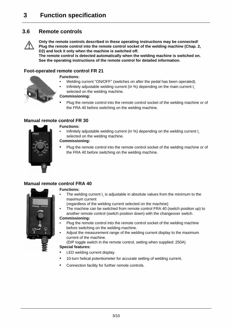
3.6 Remote controls
Only the remote controls described in these operating instructions may be connected!Plug the remote control into the remote control socket of the welding machine (Chap. 2,D2) and lock it only when the machine is switched off.The remote control is detected automatically when the welding machine is switched on.See the operating instructions of the remote control for detailed information.
Foot-operated remote control FR 21Functions:• Welding current "ON/OFF" (switches on after the pedal has been operated).• Infinitely adjustable welding current (in %) depending on the main current I1
selected on the welding machine.Commissioning:
• Plug the remote control into the remote control socket of the welding machine or ofthe FRA 40 before switching on the welding machine.
Manual remote control FR 30Functions:• Infinitely adjustable welding current (in %) depending on the welding current I1
selected on the welding machine.Commissioning:
• Plug the remote control into the remote control socket of the welding machine or ofthe FRA 40 before switching on the welding machine.
Manual remote control FRA 40Functions:• The welding current I1 is adjustable in absolute values from the minimum to the
maximum current(regardless of the welding current selected on the machine)
• The machine can be switched from remote control FRA 40 (switch position up) toanother remote control (switch position down) with the changeover switch.
Commissioning:• Plug the remote control into the remote control socket of the welding machine
before switching on the welding machine.• Adjust the measurement range of the welding current display to the maximum
current of the machine.(DIP toggle switch in the remote control, setting when supplied: 250A)
Special features:• LED welding current display.
• 10-turn helical potentiometer for accurate setting of welding current.
• Connection facility for further remote controls.
3 Function specification
3/11
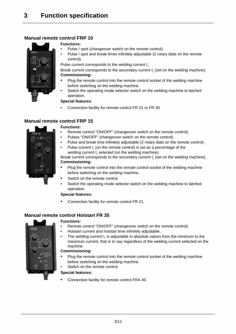
Manual remote control FRP 10Functions:• Pulse / spot (changeover switch on the remote control).• Pulse / spot and break times infinitely adjustable (2 rotary dials on the remote
control).Pulse current corresponds to the welding current I1.Break current corresponds to the secondary current I2 (set on the welding machine).Commissioning:• Plug the remote control into the remote control socket of the welding machine
before switching on the welding machine.• Switch the operating mode selector switch on the welding machine to latched
operation.Special features:
• Connection facility for remote control FR 21 or FR 30.
Manual remote control FRP 15Functions:• Remote control "ON/OFF" (changeover switch on the remote control).• Pulses "ON/OFF" (changeover switch on the remote control).• Pulse and break time infinitely adjustable (2 rotary dials on the remote control).• Pulse current I1 (on the remote control) is set as a percentage of the
welding current I1 selected (on the welding machine).Break current corresponds to the secondary current I2 (set on the welding machine).Commissioning:• Plug the remote control into the remote control socket of the welding machine
before switching on the welding machine.• Switch on the remote control.• Switch the operating mode selector switch on the welding machine to latched
operation.Special features:
• Connection facility for remote control FR 21.
Manual remote control Hotstart FR 35Functions:• Remote control "ON/OFF" (changeover switch on the remote control).• Hotstart current and hotstart time infinitely adjustable.• The welding current I1 is adjustable in absolute values from the minimum to the
maximum current, that is to say regardless of the welding current selected on themachine.
Commissioning:• Plug the remote control into the remote control socket of the welding machine
before switching on the welding machine.• Switch on the remote control.
Special features:
• Connection facility for remote control FRA 40.
3 Function specification
3/12
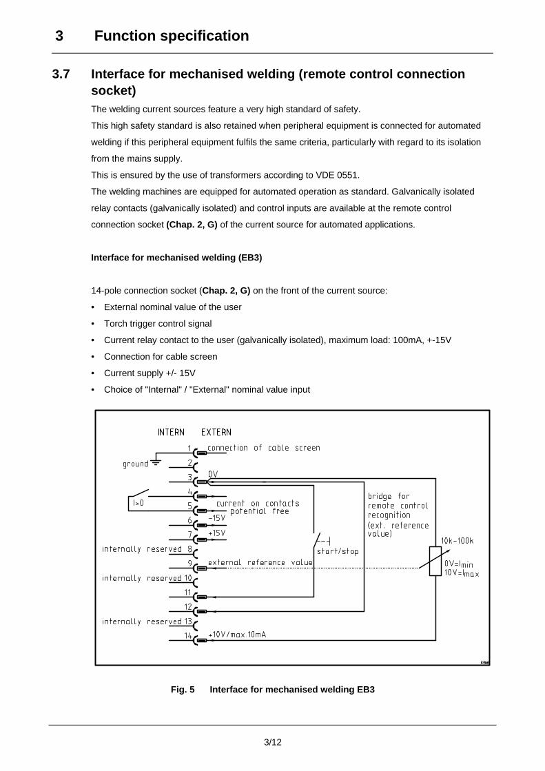
3.7 Interface for mechanised welding (remote control connectionsocket)The welding current sources feature a very high standard of safety.
This high safety standard is also retained when peripheral equipment is connected for automated
welding if this peripheral equipment fulfils the same criteria, particularly with regard to its isolation
from the mains supply.
This is ensured by the use of transformers according to VDE 0551.
The welding machines are equipped for automated operation as standard. Galvanically isolated
relay contacts (galvanically isolated) and control inputs are available at the remote control
connection socket (Chap. 2, G) of the current source for automated applications.
Interface for mechanised welding (EB3)
14-pole connection socket (Chap. 2, G) on the front of the current source:
• External nominal value of the user
• Torch trigger control signal
• Current relay contact to the user (galvanically isolated), maximum load: 100mA, +-15V
• Connection for cable screen
• Current supply +/- 15V
• Choice of "Internal" / "External" nominal value input
Fig. 5 Interface for mechanised welding EB3
4/1
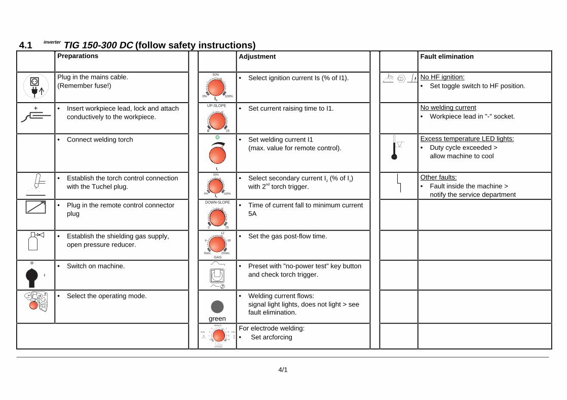
4.1 inverter TIG 150-300 DC (follow safety instructions)Preparations Adjustment Fault elimination
Plug in the mains cable.(Remember fuse!)
0% 100%IS
50%• Select ignition current Is (% of I1). No HF ignition:
• Set toggle switch to HF position.
+ • Insert workpiece lead, lock and attachconductively to the workpiece.
00 25
UP-SLOPE • Set current raising time to I1. No welding current• Workpiece lead in "-" socket.
• Connect welding torch
I1
• Set welding current I1(max. value for remote control).
Excess temperature LED lights:• Duty cycle exceeded >
allow machine to cool
• Establish the torch control connectionwith the Tuchel plug.
100%0%
50%
I2
• Select secondary current I2 (% of I1)with 2nd torch trigger.
Other faults:• Fault inside the machine >
notify the service department
• Plug in the remote control connectorplug
250
DOWN-SLOPE • Time of current fall to minimum current5A
• Establish the shielding gas supply,open pressure reducer.
0sec.
4
12
16
20sec.
GAS
• Set the gas post-flow time.
• Switch on machine.
T
• Preset with "no-power test" key buttonand check torch trigger.
• Select the operating mode.
green
• Welding current flows:signal light lights, does not light > seefault elimination.
91
0
ArcForce
10
RUTIL
3
2 CELL
BASISCH
7
8
For electrode welding:• Set arcforcing
5 Commissioning
5/1
5.1 Setting up the welding machineFollow safety instructions on the opening pages entitled “For Your Safety”.
• Set up the machine so that there is enough room to adjust the operating elements.
• Ensure that the machine is set up in a stable position and appropriately secured.
5.2 Mains connectionThe correct mains plug must be attached to the mains supply lead of the machine. Theconnection must be made by an electrician in compliance with current VDE regulations.The phase sequence is irrelevant!The operating voltage shown on the rating plate must be consistent with the mains voltage!For mains fuse protection, please refer to the "Technical data" section.
• Insert mains plug of the switched-off machine into the appropriate socket.
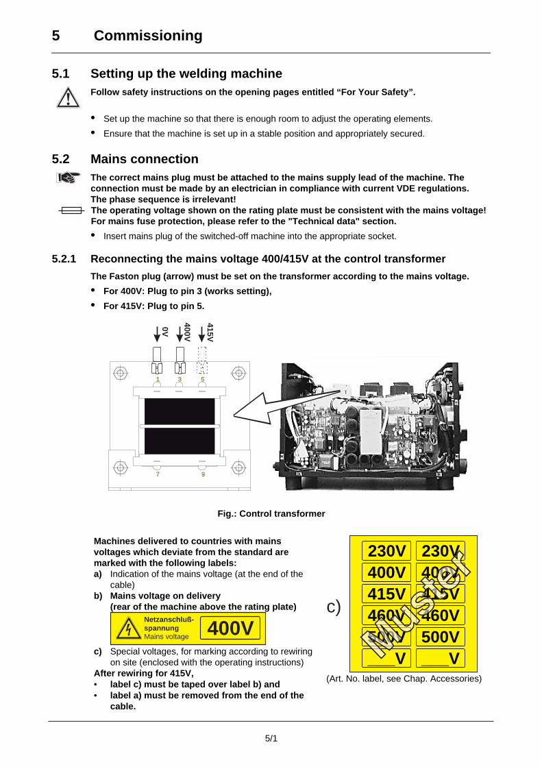
5.2.1 Reconnecting the mains voltage 400/415V at the control transformer
The Faston plug (arrow) must be set on the transformer according to the mains voltage.
• For 400V: Plug to pin 3 (works setting),
• For 415V: Plug to pin 5.
9
51
7
3
415V
400V
0V
Fig.: Control transformer
Machines delivered to countries with mainsvoltages which deviate from the standard aremarked with the following labels:a) Indication of the mains voltage (at the end of the
cable)b) Mains voltage on delivery
(rear of the machine above the rating plate)Netzanschluß-spannungMains voltage 400V
c) Special voltages, for marking according to rewiringon site (enclosed with the operating instructions)
After rewiring for 415V,• label c) must be taped over label b) and• label a) must be removed from the end of the
cable.
230V 230V400V 400V415V 415V460V 460V500V 500V___V ___V
460V500V
V
0V0V
4146
400415
00V15V
VV
c)
(Art. No. label, see Chap. Accessories)
5 Commissioning
5/2
5.3 Welding machine cooling systemObserve the following to attain the optimum duty cycle of the power components:
• Ensure that the working area is adequately ventilated,
• Do not obstruct the machine’s air inlets and outlets,
• Metal parts, dust or other foreign bodies must not get into the machine.
5.4 Workpiece leadRemove paint, rust and dirt from clamping and welding areas with a wire brush! Attach theworkpiece clamp in the immediate vicinity of the welding position! Structural parts, pipes,rails etc. may not be used as return leads for the welding current if they are not theworkpiece themselves!A perfect current connection must be ensured where welding benches and appliances areconcerned.
• Insert cable plug of the workpiece lead into the welding current socket (Chap.2, B) and lock byturning to the right.
MMA welding:The polarity depends on the instructions of the electrode manufacturer on the electrodepackaging.
5.5 Electrode holder connection (MMA welding)• Insert cable plug of the stick electrode holder into the welding current socket "+" (Chap. 2, B) or
"-" (Chap. 2, C") and lock by turning to the right.The polarity depends on the instructions of the electrode manufacturer on the packaging.
5.6 General information on connection of the welding torchWe can only guarantee the perfect functioning of our machines when they are used withour range of welding torches.TIG welding torches with a shielded torch trigger control line should not be connected!
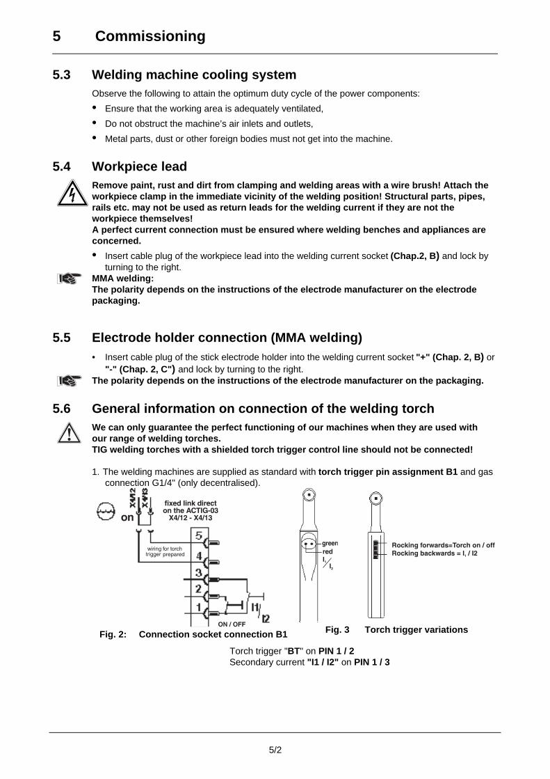
1. The welding machines are supplied as standard with torch trigger pin assignment B1 and gasconnection G1/4" (only decentralised).
Fig. 2: Connection socket connection B1 Fig. 3 Torch trigger variations
Torch trigger "BT" on PIN 1 / 2Secondary current "I1 / I2" on PIN 1 / 3
5 Commissioning
5/3
5.6.1 TIG welding torch
Prepare welding torch according to the welding task in hand (see operating instructions ofthe torch).• Plug the torch trigger plug into the socket (Chap. 2, E) and tighten.• Engage the rapid-action closure nipple of the TIG torch in the rapid-action closure coupling for
the coolant supply (blue) and return (red) lines (only for water-cooled torches).Decentralised:• Plug the welding current cable (if it exists) into the socket (Chap. 2, C) and lock by turning to the right.• Screw the gas connection tightly to the connecting nipple G¼ (Chap. 2, D)
(welding current potential “-”).Central:• Plug the central connecting plug into the central connection socket and tighten with the box nut .
5.6.2 TIG potentiometer welding torch
The welding machine must be equipped with the "potentiometer torch connection facility"option to be able to operate a TIG potentiometer welding torch(if necessary fit "ASM potentiometer" option, see Accessories Chap.).Prepare welding torch according to the welding task in hand (see operating instructions ofthe torch).• Plug the torch trigger plug into the socket (Chap.2, E) and tighten.• Plug the control cable plug into the socket (Chap.2, G) and tighten.• Engage the rapid-action closure nipple of the torch in the rapid-action closure coupling for
the coolant supply (blue) and return (red) lines (only for water-cooled torches).Decentralised:• Plug the welding current cable (if it exists) into the socket (Chap. 2, C) and lock by turning
to the right.• Screw the gas connection tightly to the connecting nipple G¼ (Chap. 2, D)
(welding current potential “-”).Central:• Plug the central connecting plug into the central connection socket and tighten with the box nut.
5.7 Shielding gas supply5.7.1 Establishing the gas connections
Place the shielding gas cylinder in the cylinder holder and secure it against accidents withthe securing chain!
No impurities must be allowed to enter the shielding gas supply, as these would otherwisecause blockages. Before connecting the pressure reducer to the gas cylinder, open thecylinder valve briefly to blow out any dirt present.All shielding gas connections must be gastight!
• Mount the pressure reducer on the gas cylinder valve.
• Screw the gas hose gastight to the pressure reducer and connecting nipple G ¼" on the rear ofthe welding machine.
5 Commissioning
5/4
5.7.2 Currentless testing and setting the amount of shielding gas
Consequences of incorrect shielding gas settings:Insufficient shielding gas: inadequate gas protection, the indrawn air leads to pores in
the weld seam.Excessive shielding gas: turbulence may occur, as a result of which air
can penetrate and lead to pores in the weld seam.
• Switch on the machine at the main switch (Chap.2, A).
• Select latched operation mode with the program selector switch (Chap. 3, A1).
• Switch on the changeover switch (currentless test) (Chap. 3, J1) (position T)
• Press and release the torch trigger.
• Slowly open the gas cylinder valve.
• Allow the currentless test to proceed, and if necessary correct the welding current, UP-SlopeDOWN-Slope, secondary current etc.
• Set the required amount of shielding gas on the pressure reducer, about 4 – 15 l/min dependingon the current strength and the material.
• Switch off the pre-selection switch (currentless test) (position 0)
The machine is now ready for welding!
6 Adjusting instructions
inwo
rking
7 Maintenance and care
7/1
Under normal operating conditions these welding machines are largely maintenance-free andrequire a minimum of care. However, a number of points should be observed to guarantee fault-freeoperation of your welding machine. Among these are regular cleaning and checking, as describedbelow, depending on the level of contamination in the environment and the usage time of thewelding machine.
Cleaning, testing and repairing of the welding machines may only be carried out bycompetent personnel. In the event of failure to comply with any one of the following teststhe machine must not be operated again until the fault has been rectified.
7.1 Cleaning
To do this, carefully disconnect the machine from the mains. PULL OUT THE MAINS PLUG!
(Switching off or unscrewing the fuse is not adequate isolation).
Wait for 2 minutes until the capacitors have discharged. Remove the casing cover.
The individual components should be handled as follows:
Current source Depending on the amount of dust, blow out current source using oil- and
moisture-free compressed air.
Electronics, circuit boards Do not blow on electronic components or circuit boards with the
compressed air stream but suck clean using a vacuum cleaner.
7.2 Repetition test according to VDE 0702 and VBG 15
The following description of the repetition test is merely an extract from the detailed test
instructions. If required, a copy can be requested from us.
You are recommended to carry out a quarterly and an annual check. The annual test should also becarried out after every repair.
Test sequence:
Quarterly test: 1. Visual check of correct condition2. Measurement of protective conductor resistance
Annual test: 1. Visual check of correct condition2. Measurement of protective conductor resistance3. Measurement of insulation resistance following internal
cleaning of the power source4. Measurement of open circuit voltage5. Function test of the welding machine
7.2.1 Visual check of correct conditionThe machine must be inspected for externally visible faults (without opening the machine). Duringthis inspection, attention must be paid, for example, to the following points:• External faults in mains plug and mains cable, e.g. insulation faults, scorch or pressure marks.• Defects in anti-kink protection and the strain relief of the connection lead, mains switch.• Faults in welding leads, tube package, plug fixture, arc torch.• Signs of an overload and improper use.• Damage to stop points and casing.• Improper interference and modifications.• The type plate and warning symbol must be present and legible.
Die im Kapitel "Wartung und Pflege" aufgeführten Hinweise, Richtlinien und Normen wurden
grundlegend überarbeitet und sind aus diesem Grund nicht mehr gültig!
Die relevanten Hinweise, Richtlinien und Normen finden Sie in den beiliegenden
Ergänzungsblättern "Allgemeine Hinweise zu 3 Jahre Garantie", Art. Nr.: 099-000GAR-EWMxx.
Sollten die Dokumente nicht vorliegen, können diese über den autorisierten Fachhändler
angefordert werden!Außerachtlassung kann lebensgefährlich sein!
The instructions, guidelines and standards given in the "Maintenance and Care" chapter have
been completely revised and are therefore no longer valid!
The relevant instructions, guidelines and standards can be found in the enclosed supplements
"General notes on the 3 year warranty",item no.: 099-000GAR-EWMxx.
If these documents are missing, they can be requested from your authorised specialist dealer!
Not observing these instructions can be potentially fatal!Les consignes, directives et normes indiquées au chapitre « Maintenance et entretien » ont été
mises à jour et ne sont donc plus valables !
Vous trouverez les consignes, directives et normes applicables dans les additifs « Consignes
générales relatives à la garantie de 3 ans », à l´article : 099-000GAR-EWMxx.
Si vous ne possédez pas les documents, vous pouvez vous les procurer auprès de votre
revendeur autorisé !Le non-respect des consignes peut représenter un danger de mort !Le istruzioni, direttive e norme presenti nel capitolo „Manutenzione e cura” sono state
completamente riviste e per questo motivo non sono più valide!
Le istruzioni, direttive e norme rilevanti le trovate nell'aggiornamento qui allegato “Istruzioni
generali sui 3 anni di garanzia”, Nr. Art.: 099-000GAR-EWMxx.
Se i documenti non fossero disponibili, possono essere richiesti al rivenditore autorizzato!
L'inosservanza delle istruzioni può comportare pericolo di vita!
D
F
GB
I
7 Maintenance and care
7/2
7.2.2 Measurement of protective conductor resistance
Measure between safety contact of the mains plug and metal parts which can be touched, e.g.
casing screws. During measuring, the entire length of the machine’s connection lead, especially
near the connection points, must be moved.
The resistance must be < 0.1Ω. The measurement must be performed using at least 200 mA.
7.2.3 Measurement of insulation resistance
The machine must be disconnected from the mains. Open the welding machine and clean carefully
as described in Chap. 7.1. Switch on mains switch.
• Insulation resistance mains current circuit - casing: Measure from a connection of the mains
plug to the casing. The resistance must be > 2.5 MΩ.
• Insulation resistance welding current circuit - casing: Measure between a welding socket
and protective conductor. The resistance must be > 2.5 MΩ.
• Insulation resistance mains current circuit - welding current circuit: Measure from a
connection of the mains plug to a welding current socket. The resistance must be > 5.0 MΩ.
7.2.4 Measurement of open circuit voltage (according to EN 60974-1 /
VDE 0544 T1)
-
+
6u8F10nF
0...5k
Meqsurement circuit for peak values
Input
0k2
1k0 Diode similar 1N 4007
V
Connect the measuring circuit to the
welding current sockets as shown in Fig. 1.
The voltmeter must indicate the mean
value. Adjust the potentiometer from 0kΩ to
5kΩ during the measurement.
The measured voltage must not deviate
from that specified on the rating plate (U0)
by more than 10%.
7.2.5 Function test of the welding machine
Carry out a function test depending on the type of machine.
7.3 Repair workRepair and maintenance work may only be performed by specialist staff. In all service matters,always consult your dealer. Return deliveries of defective equipment subject to warranty may onlybe made through your dealer.When replacing parts, use only original spare parts.When ordering spare parts, the machine type, serial number and item number of the machine, aswell as the type description and item number of the spare part must be quoted.If repair or maintenance work is carried out on this machine by personnel who are not trained andauthorised to undertake such work, the right to claim under the warranty lapses.
8 Operating problems, causes and remedies
8/1
All machines are subjected to strict manufacturing and final inspection procedures. If, despite this,
something fails to work at any time, please check machine using the following process chart. If
none of the fault elimination procedures described leads to the correct functioning of the machine,
please inform your authorised dealer.
8.1 Customer checklist8.1.1 Customer checklist (inverter TIG 150 DC)
Switch on the machine(at the mains switch (Kap. 2, A)
Yes
Machine functioning No• Mains supply broken• Mains plug not inserted• Mains fuse faulty• Mains power switch faulty
Yes
Press torch trigger
Yes
Green LED lights (Kap. 3, H1)power unit / "on" No
• Torch connection incorrect (check torchlead according to circuit diagram)
• Torch control cable not inserted• Torch or torch trigger faulty
Yes
Shielding gas is expelled No • No shielding gas connected• Pressure reducer turned off
Yes
Open circuit voltage No • Test switch (Kap. 3, J1) in „test“ position (Option)
• yellow LED (Kap. 3, I1) excess temperaturelights (allow machine to cool down)
YesHF is applied No • HF toggle switch on Lift-Arc ignition
Yes
Welding currentNo • Welding torch faulty
• Workpiece lead connected• Workpiece lead in wrong socket
Yes
Good welding propertiesNo
• Leaky shielding gas supply• Welding torch damaged• Tungsten electrode contaminated• insufficient or excessive shielding gas
Yes
Remote control functionsNo • Remote control plug not inserted in the
machine• Remote control or cable defective
8 Operating problems, causes and remedies
8/2
8.1.2 Customer checklist (inverter TIG 200 DC powerSinus)
Switch on the machine(at the mains switch (Kap. 2, A)
Yes
Machine functioning No• Mains supply broken• Mains plug not inserted• Mains fuse faulty• Mains power switch faulty• Mains plug wrongly connected
Yes
Press torch trigger
Yes
Green LED lights (Kap. 3, H1)power unit / "on" No
• Torch connection incorrect (check torchlead according to circuit diagram)
• Torch control cable not inserted• Torch or torch trigger faulty
Yes
Shielding gas is expelled No • No shielding gas connected• Pressure reducer turned off
Yes
Open circuit voltage No • Test switch (Kap. 3, J1) in „test“ position (Option)
• yellow LED (Kap. 3, I1) excess temperaturelights (allow machine to cool down)
YesHF is applied No • HF toggle switch on Lift-Arc ignition
Yes
Welding currentNo • Welding torch faulty
• Workpiece lead connected• Workpiece lead in wrong socket
Yes
Good welding propertiesNo
• Leaky shielding gas supply• Welding torch damaged• Tungsten electrode contaminated• insufficient or excessive shielding gas
Yes
Remote control functionsNo • Remote control plug not inserted in the
machine• Remote control or cable defective
8 Operating problems, causes and remedies
8/3
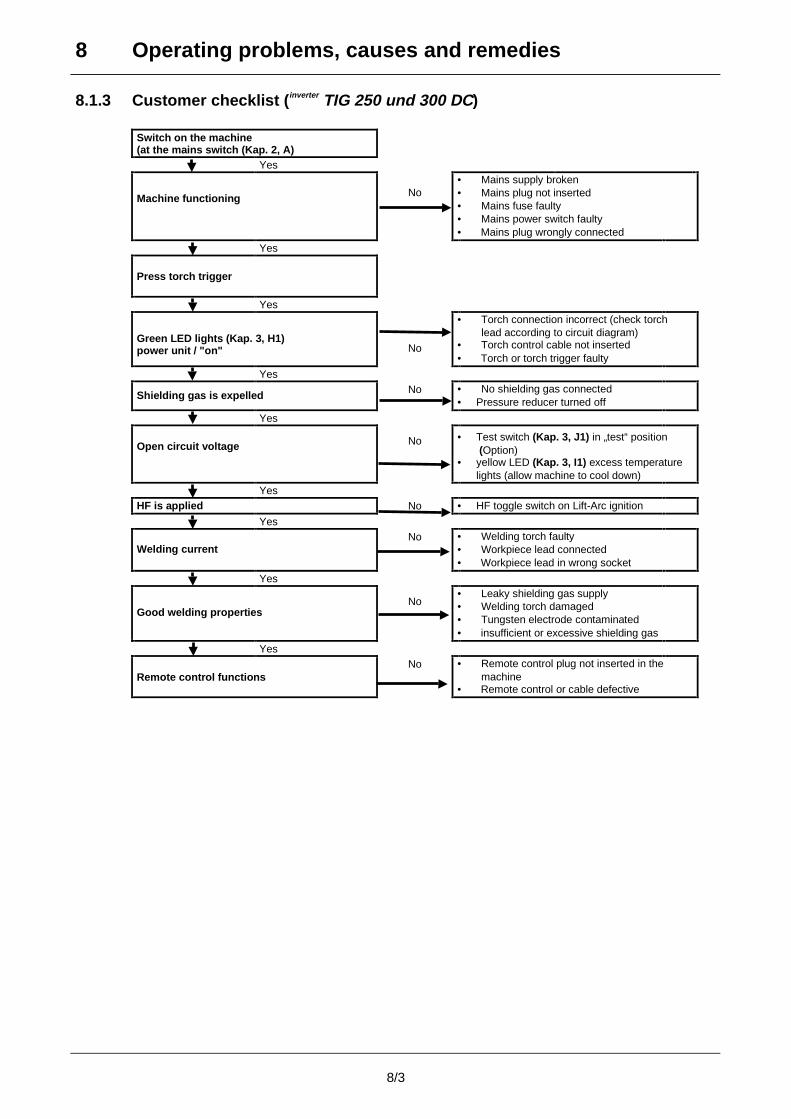
8.1.3 Customer checklist (inverter TIG 250 und 300 DC)
Switch on the machine(at the mains switch (Kap. 2, A)
Yes
Machine functioning No• Mains supply broken• Mains plug not inserted• Mains fuse faulty• Mains power switch faulty• Mains plug wrongly connected
Yes
Press torch trigger
Yes
Green LED lights (Kap. 3, H1)power unit / "on" No
• Torch connection incorrect (check torchlead according to circuit diagram)
• Torch control cable not inserted• Torch or torch trigger faulty
Yes
Shielding gas is expelled No • No shielding gas connected• Pressure reducer turned off
Yes
Open circuit voltage No • Test switch (Kap. 3, J1) in „test“ position (Option)
• yellow LED (Kap. 3, I1) excess temperaturelights (allow machine to cool down)
YesHF is applied No • HF toggle switch on Lift-Arc ignition
Yes
Welding currentNo • Welding torch faulty
• Workpiece lead connected• Workpiece lead in wrong socket
Yes
Good welding propertiesNo
• Leaky shielding gas supply• Welding torch damaged• Tungsten electrode contaminated• insufficient or excessive shielding gas
Yes
Remote control functionsNo • Remote control plug not inserted in the
machine• Remote control or cable defective
9 Ersatzteilliste / Spare parts list
9/1
Abb. 11 Vorderseite inverter TIG 150 DC und inverter TIG 200 DC powerSinus
Fig. 11 Front view inverter TIG 150 DC and inverter TIG 200 DC powerSinus
Abb. 12 Vorderseite inverter TIG 250 DC und inverter TIG 300 DCFig. 12 Front view inverter TIG 250 DC and inverter TIG 300 DC
9 Ersatzteilliste / Spare parts list
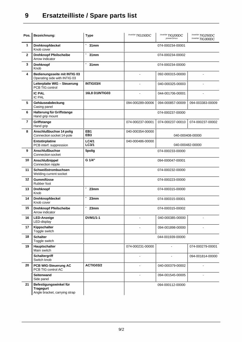
9/2
Pos. Bezeichnung: Type inverterTIG150DC inverterTIG200DCpowerSinus
inverterTIG250DCinverterTIG300DC
1 DrehknopfdeckelKnob cover
∅ 31mm 074-000234-00001
2 Drehknopf PfeilscheibeArrow indicator
∅ 31mm 074-000234-00002
3 DrehknopfKnob
∅ 31mm 074-000234-00000
4 Bedienungsseite mit INTIG 03Operating side with INTIG 03
- 092-000315-00000 -
Leiterplatte WIG – SteuerungPCB TIG control
INTIG03/4 - 040-000325-00003 -
IC PALIC PAL
16L8 D1INTIG03 - 044-001706-00001 -
5 GehäuseabdeckungCasing panel
094-000289-00006 094-000857-00009 094-003383-00009
6 Halterung für GriffstangeHand grip mount
074-000237-00000
7 GriffstangeHand grip
074-000237-00001 074-000237-00010 074-000237-00002
8 Anschlußbuchse 14 poligConnection socket 14-pole
EB1EB3
040-000354-00000040-000408-00000
EntstörplatinePCB interf. suppression
LC4/1LC3/1
040-000486-00000040-000482-00000
9 AnschlußbuchseConnection socket
5polig 074-000233-00000
10 AnschlußnippelConnection nipple
G 1/4" 094-000047-00001
11 SchweißstrombuchsenWelding current socket
074-000232-00000
12 GummifüsseRubber foot
074-000223-00000
13 DrehknopfKnob
∅ 23mm 074-000315-00000
14 DrehknopfdeckelKnob cover
∅ 23mm 074-000315-00001
15 Drehknopf PfeilscheibeArrow indicator
∅ 23mm 074-000315-00002
16 LED-AnzeigeLED-display
DVM1/1-1 - 040-000385-00000 -
17 KippschalterToggle switch
- 094-001898-00000 -
18 SchalterToggle switch
044-001939-00000
19 HauptschalterMain switch
074-000231-00000 - 074-000279-00001
SchaltergriffSwitch knob
- - 094-001814-00000
20 PCB WIG-Steuerung ACPCB TIG control AC
ACTIG03/2 - 040-000379-00002 -
SeitenwandSide panel
- 094-001545-00005 -
21 Befestigungswinkel fürTragegurtAngle bracket, carrying strap
094-000112-00000
9 Ersatzteilliste / Spare parts list
9/3
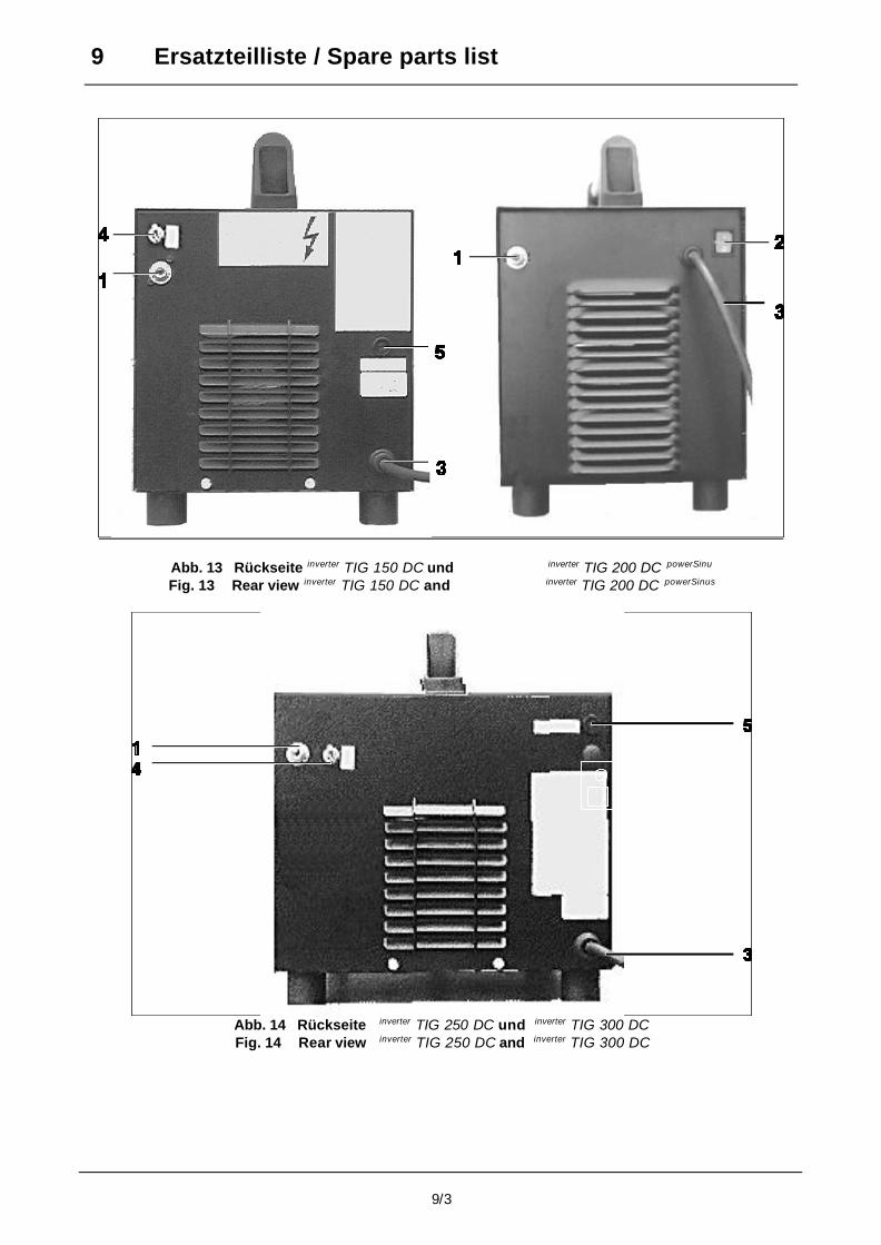
Abb. 13 Rückseite inverter TIG 150 DC und inverter TIG 200 DC powerSinu
Fig. 13 Rear view inverter TIG 150 DC and inverter TIG 200 DC powerSinus
Abb. 14 Rückseite inverter TIG 250 DC und inverter TIG 300 DCFig. 14 Rear view inverter TIG 250 DC and inverter TIG 300 DC

9 Ersatzteilliste / Spare parts list
9/4
Pos. Bezeichnung: Type inverterTIG150DC inverterTIG200DCpowerSinus
inverterTIG250DCinverterTIG300DC
1 Magnetventil 1/4"
Solenoid valve
074-000227-00000
2 Hauptschalter
Main switch
- 074-000231-00000 -
3 Netzkabel
Mains cable
074-000236-00001 074-000236-00001 094-000002-00000
4 Schalter
Toggle switch
044-001939-00000 - 044-001939-00000
5 Sicherung träge
Fuse slow-blowing
094-000202-00000 - 094-000202-00000
9 Ersatzteilliste / Spare parts list
9/5
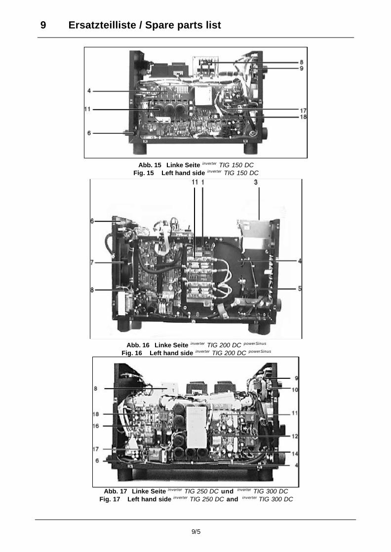
Abb. 15 Linke Seite inverter TIG 150 DCFig. 15 Left hand side inverter TIG 150 DC
Abb. 16 Linke Seite inverter TIG 200 DC powerSinus
Fig. 16 Left hand side inverter TIG 200 DC powerSinus
Abb. 17 Linke Seite inverter TIG 250 DC und inverter TIG 300 DCFig. 17 Left hand side inverter TIG 250 DC and inverter TIG 300 DC
9 Ersatzteilliste / Spare parts list
9/6
Pos. Bezeichnung: Type inverterTIG150DC inverterTIG200DCpowerSinus
inverterTIG250DCinverterTIG300DC
1 PCB SchutzbeschaltungPCB protactive wiring
DSB5/1 - 040-000448-00000 -
2 SekundärDioden Kühler
SKD6xD370-04F
6xD70-04F
- 072-000330-00000 -
3 ZündgerätIgnition unit
HF-DC1/42 - 040-000309-00000 -
4 InverterbausatzInverter kit
WIG DC26V/150A 220V-S
WIG DC28V/200A 230/240V-S
WIG DC30V/250A 3x380V-SWIG DC32V/300A 3x400V-L
070-000019-00000
070-000040-00000
070-000005-00000070-000036-00001
5 ShuntShunt
150A/60mV 074-000359-00000 074-000359-00000 074-000034-00000
6 KabeldurchführungCable bushing
074-000283-00000 074-000283-00000 074-000243-00000
7 LüfterFan
- 074-000015-00000 -
8 VersorgungstrafoSupply transformer
EI 84a/59VA/230-43-20V
EI66a/21VA/230V-110-42V
EI66a/24VA/415-400-42-0V
074-000298-00000
074-000496-00004
094-000588-00001
9 PCB WIG-SteuerungPCB TIG control
INTIG03/4 040-000325-00003 - 040-000325-00003
IC PALIC PAL
16L8 D1INTIG03 044-001706-00001 - 044-001706-00001
11 PrimärschalterPrimary switch
INV 25/500
DI 70-04GF15
D 70-04GF15
INV40/1000-1.6M
INV45/1000-2.6M
080-000235-00000
080-000179-00004
080-000178-00004
080-000270-00000
080-000261-00000
12 PrimärschalterPrimary switch
INV40/1000-1.6P
INV45/1000-2.6P
- - 080-000271-00000
080-000262-00000
13 Durchflußwandler DC 3.9/220V-02
DW 7,5/3x380V-01
072-000135-00000 -
072-000032-00000
14 PCB TreiberelektronikPCB driver electronic
TRI 1/1 - - 040-000294-00000
15 VaristormodulVaristor module
SB460/6 - - 072-000292-00000
16 PCB SperrwandlerPCB blocking converter
- - 040-000289-00000
17 NetzgleichrichterMains rectifier
B2 35/12
B6 105/16
080-000238-00012 -
080-000205-00016
18 Thyristor-ModulThyristor module
MT 32-10
MTD55-14A
080-00253-00010 -
064-000083-00014
9 Ersatzteilliste / Spare parts list
9/7
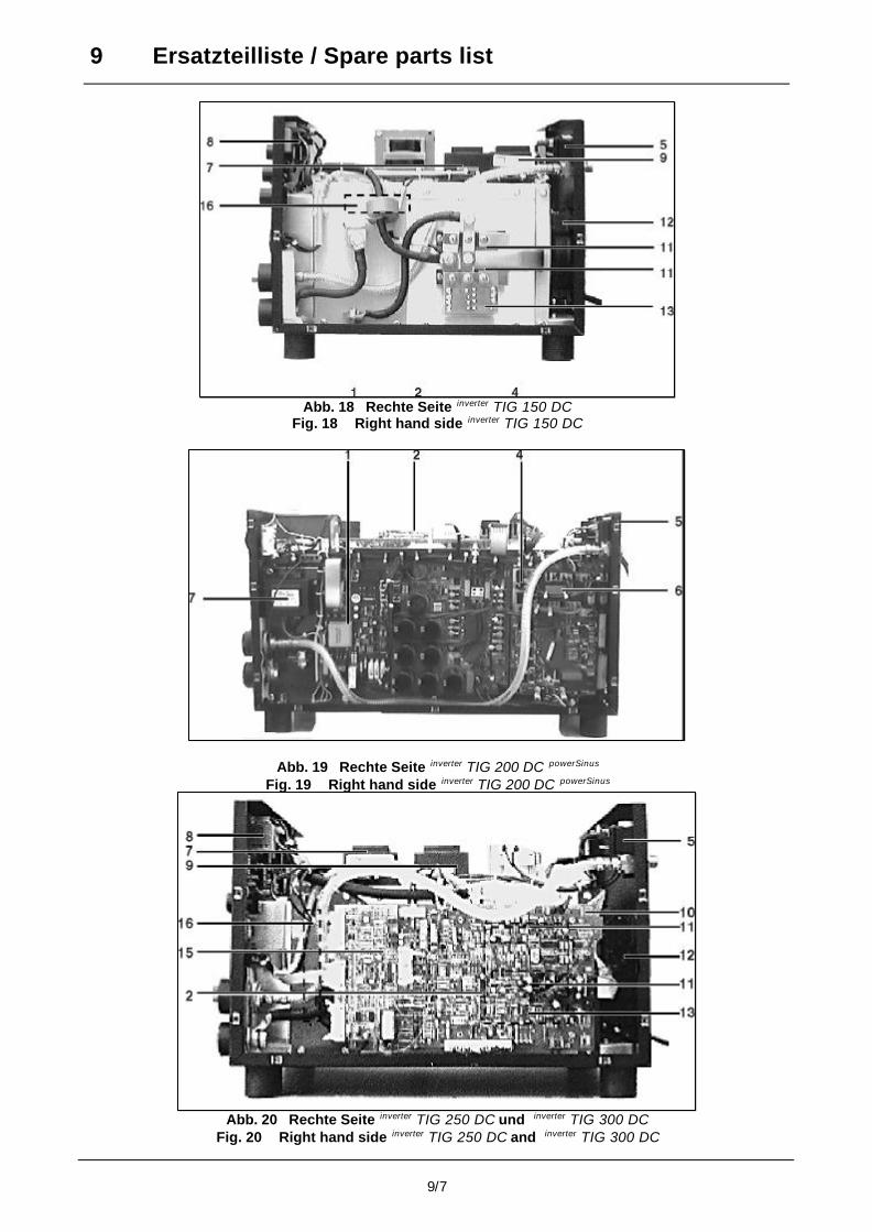
Abb. 18 Rechte Seite inverter TIG 150 DCFig. 18 Right hand side inverter TIG 150 DC
Abb. 19 Rechte Seite inverter TIG 200 DC powerSinus
Fig. 19 Right hand side inverter TIG 200 DC powerSinus
Abb. 20 Rechte Seite inverter TIG 250 DC und inverter TIG 300 DCFig. 20 Right hand side inverter TIG 250 DC and inverter TIG 300 DC
9 Ersatzteilliste / Spare parts list
9/8
Pos. Bezeichnung: Type inverterTIG150DC inverterTIG200DCpowerSinus
inverterTIG250DCinverterTIG300DC
1 PCB SperrwandlerPCB blocking converter
SPW3/2 - 040-000474-00000 -
2 PCB Haupt-regelungselektronikPCB main regulatorelectr.onic
TRSQW3/200/1TRDC2/250/6TRDC2/300/2
- 040-000451-00000040-000290-00015040-000290-00018
3 Durchflußwandler DC 5.0/220V-02 072-000347-00000 -
4 NetzgleichrichterMains rectifier
B2 35/12 080-000233-00012 -
5 MagnetventilSolenoid valve
094-000472-00001
6 PCB HochsetzstellerPCB power factorcorrection
PFC1/1PCB - 040-000455-00000 -
7 HF – FilterHF filter
HF 1-3 040-000284-00000
8 PCB WIG-SteuerungPCB TIG control
INTIG03/4 040-000325-00003
IC PALIC PAL
16L8 D1INTIG03 044-001706-00001 044-001706-00001
9 ZündgerätIgnition unit
HF-DC1/42 040-000309-00000 - 040-000309-00000
10 PCB LüfteransteuerungPCB fan control
Relais1 - - 040-000404-00000
11 Sekundär Gleichrichter-diode und FreilaufdiodeSec. diode rectifier recov.diode
MDDM 95-04 F02MDDM120-04 F02
080-000149-00004 -080-000257-00004
12 LüfterFan
074-000015-00000 - 074-000015-00000
13 PCBSchutzbeschaltungPCB protective wiring
DSB1/1DSB3/5
040-000298-00000 -040-000446-00000
14 SekundärDioden KühlerSecundary diode cooler
SDK 2x MDDM 95-04 F02-01/3SDK 2x MDDM 120-04 F02-01/2
072-000159-00000 -072-000154-00000
15 PCB (Liftarc)PCB (liftarc)
Lift 1/DC - - 040-000434-00000
16 ShuntShunt
150A/60mV250A/60mV
074-000359-00000 -074-000034-00000
10 Zubehör
10/1
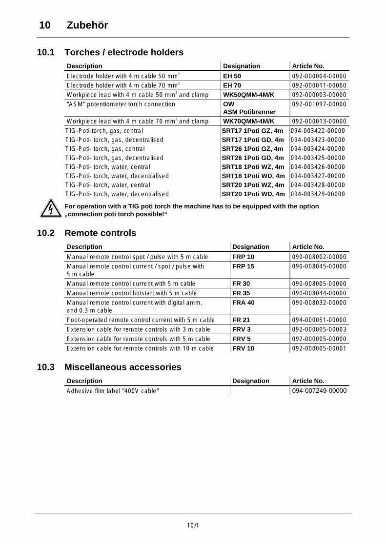
10.1 Torches / electrode holdersDescription Designation Article No.
Electrode holder with 4 m cable 50 mm2 EH 50 092-000004-00000
Electrode holder with 4 m cable 70 mm2 EH 70 092-000011-00000
Workpiece lead with 4 m cable 50 mm2 and clamp WK50QMM-4M/K 092-000003-00000
"ASM" potentiometer torch connection OWASM Potibrenner
092-001097-00000
Workpiece lead with 4 m cable 70 mm2 and clamp WK70QMM-4M/K 092-000013-00000
TIG-Poti-torch, gas, central SRT17 1Poti GZ, 4m 094-003422-00000TIG-Poti- torch, gas, decentralised SRT17 1Poti GD, 4m 094-003423-00000TIG-Poti- torch, gas, central SRT26 1Poti GZ, 4m 094-003424-00000TIG-Poti- torch, gas, decentralised SRT26 1Poti GD, 4m 094-003425-00000TIG-Poti- torch, water, central SRT18 1Poti WZ, 4m 094-003426-00000TIG-Poti- torch, water, decentralised SRT18 1Poti WD, 4m 094-003427-00000TIG-Poti- torch, water, central SRT20 1Poti WZ, 4m 094-003428-00000TIG-Poti- torch, water, decentralised SRT20 1Poti WD, 4m 094-003429-00000
For operation with a TIG poti torch the machine has to be equipped with the option„connection poti torch possible!“
10.2 Remote controlsDescription Designation Article No.
Manual remote control spot / pulse with 5 m cable FRP 10 090-008002-00000
Manual remote control current / spot / pulse with5 m cable
FRP 15 090-008045-00000
Manual remote control current with 5 m cable FR 30 090-008005-00000
Manual remote control hotstart with 5 m cable FR 35 090-008044-00000
Manual remote control current with digital amm.and 0.3 m cable
FRA 40 090-008032-00000
Foot-operated remote control current with 5 m cable FR 21 094-000051-00000
Extension cable for remote controls with 3 m cable FRV 3 092-000005-00003
Extension cable for remote controls with 5 m cable FRV 5 092-000005-00000
Extension cable for remote controls with 10 m cable FRV 10 092-000005-00001
10.3 Miscellaneous accessoriesDescription Designation Article No.
Adhesive film label "400V cable" 094-007249-00000
11 HF pulse generator HF-DC1/42 and ZGP1/8.0-42
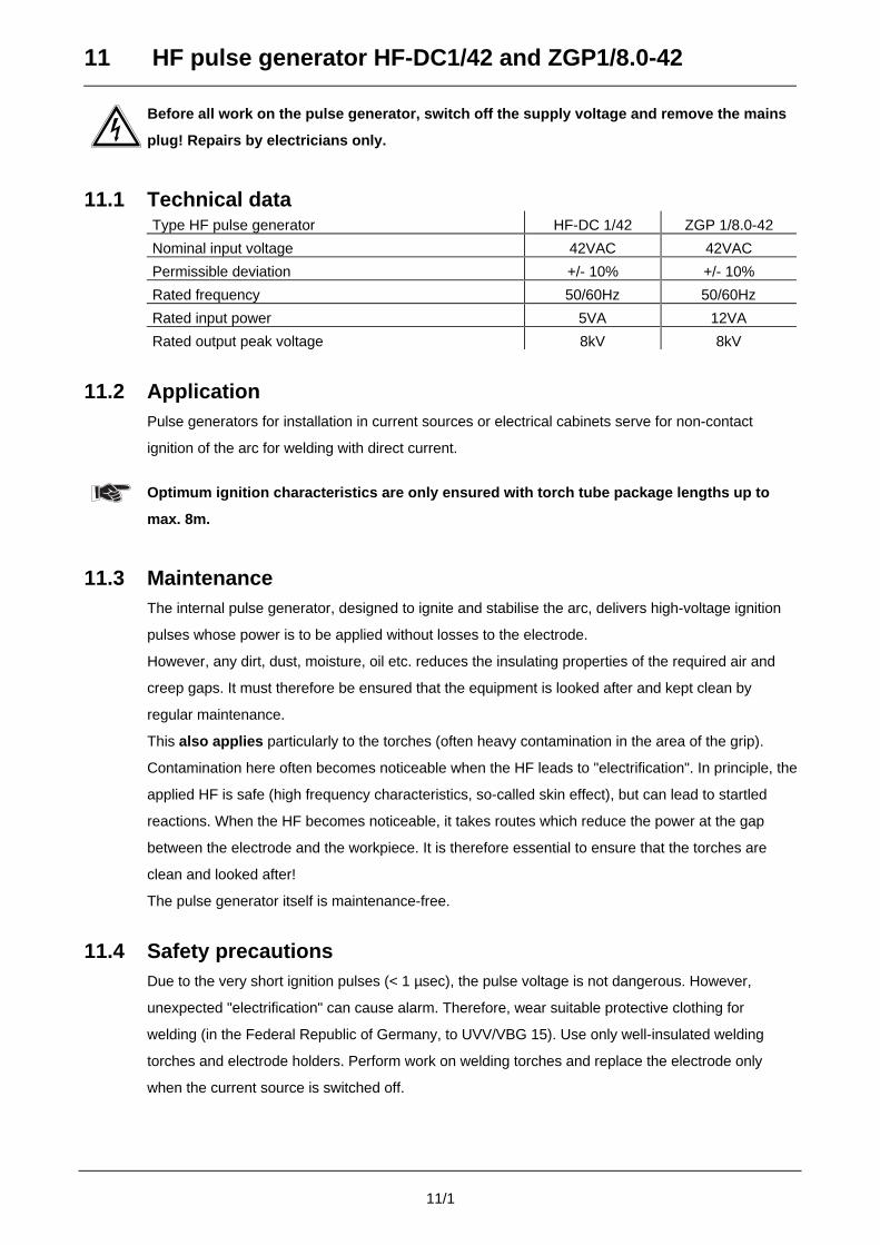
11/1
Before all work on the pulse generator, switch off the supply voltage and remove the mains
plug! Repairs by electricians only.
11.1 Technical dataType HF pulse generator HF-DC 1/42 ZGP 1/8.0-42
Nominal input voltage 42VAC 42VAC
Permissible deviation +/- 10% +/- 10%
Rated frequency 50/60Hz 50/60Hz
Rated input power 5VA 12VA
Rated output peak voltage 8kV 8kV
11.2 ApplicationPulse generators for installation in current sources or electrical cabinets serve for non-contact
ignition of the arc for welding with direct current.
Optimum ignition characteristics are only ensured with torch tube package lengths up to
max. 8m.
11.3 MaintenanceThe internal pulse generator, designed to ignite and stabilise the arc, delivers high-voltage ignition
pulses whose power is to be applied without losses to the electrode.
However, any dirt, dust, moisture, oil etc. reduces the insulating properties of the required air and
creep gaps. It must therefore be ensured that the equipment is looked after and kept clean by
regular maintenance.
This also applies particularly to the torches (often heavy contamination in the area of the grip).
Contamination here often becomes noticeable when the HF leads to "electrification". In principle, the
applied HF is safe (high frequency characteristics, so-called skin effect), but can lead to startled
reactions. When the HF becomes noticeable, it takes routes which reduce the power at the gap
between the electrode and the workpiece. It is therefore essential to ensure that the torches are
clean and looked after!
The pulse generator itself is maintenance-free.
11.4 Safety precautionsDue to the very short ignition pulses (< 1 µsec), the pulse voltage is not dangerous. However,
unexpected "electrification" can cause alarm. Therefore, wear suitable protective clothing for
welding (in the Federal Republic of Germany, to UVV/VBG 15). Use only well-insulated welding
torches and electrode holders. Perform work on welding torches and replace the electrode only
when the current source is switched off.
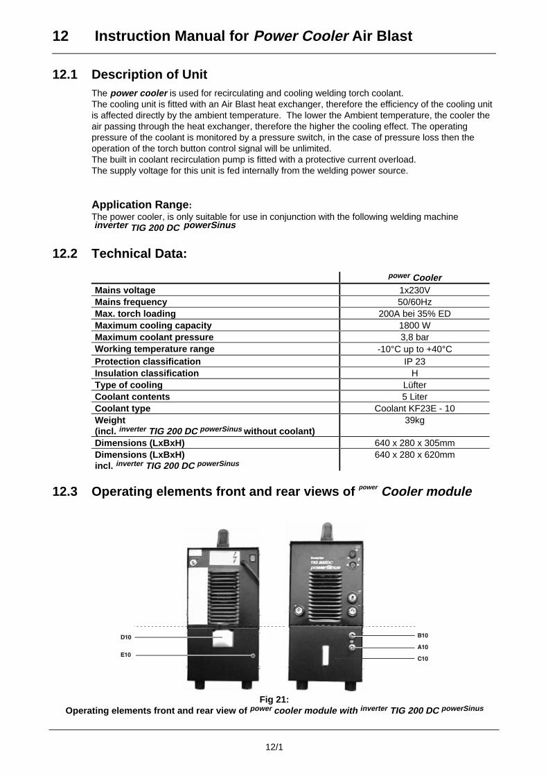
12 Instruction Manual for Power Cooler Air Blast
12/1
12.1 Description of UnitThe power cooler is used for recirculating and cooling welding torch coolant.The cooling unit is fitted with an Air Blast heat exchanger, therefore the efficiency of the cooling unitis affected directly by the ambient temperature. The lower the Ambient temperature, the cooler theair passing through the heat exchanger, therefore the higher the cooling effect. The operatingpressure of the coolant is monitored by a pressure switch, in the case of pressure loss then theoperation of the torch button control signal will be unlimited.The built in coolant recirculation pump is fitted with a protective current overload.The supply voltage for this unit is fed internally from the welding power source.
Application Range:The power cooler, is only suitable for use in conjunction with the following welding machine inverter TIG 200 DC powerSinus
12.2 Technical Data:
power CoolerMains voltage 1x230VMains frequency 50/60HzMax. torch loading 200A bei 35% EDMaximum cooling capacity 1800 WMaximum coolant pressure 3,8 barWorking temperature range -10°C up to +40°CProtection classification IP 23Insulation classification HType of cooling LüfterCoolant contents 5 LiterCoolant type Coolant KF23E - 10Weight(incl. inverter TIG 200 DC powerSinus without coolant)
39kg
Dimensions (LxBxH) 640 x 280 x 305mmDimensions (LxBxH)incl. inverter TIG 200 DC powerSinus
640 x 280 x 620mm
12.3 Operating elements front and rear views of power Cooler module
Fig 21:Operating elements front and rear view of power cooler module with inverter TIG 200 DC powerSinus
12 Instruction Manual for Power Cooler Air Blast
12/2
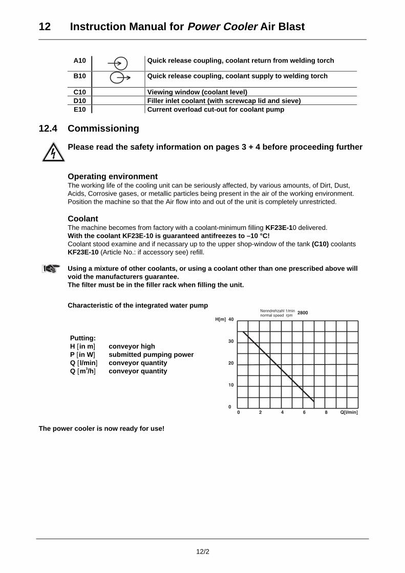
A10 Quick release coupling, coolant return from welding torch
B10 Quick release coupling, coolant supply to welding torch
C10 Viewing window (coolant level)D10 Filler inlet coolant (with screwcap lid and sieve)E10 Current overload cut-out for coolant pump
12.4 Commissioning
Please read the safety information on pages 3 + 4 before proceeding further
Operating environmentThe working life of the cooling unit can be seriously affected, by various amounts, of Dirt, Dust,Acids, Corrosive gases, or metallic particles being present in the air of the working environment.Position the machine so that the Air flow into and out of the unit is completely unrestricted.
CoolantThe machine becomes from factory with a coolant-minimum filling KF23E-10 delivered.With the coolant KF23E-10 is guaranteed antifreezes to –10 °C!Coolant stood examine and if necassary up to the upper shop-window of the tank (C10) coolantsKF23E-10 (Article No.: if accessory see) refill.
Using a mixture of other coolants, or using a coolant other than one prescribed above willvoid the manufacturers guarantee.The filter must be in the filler rack when filling the unit.
Characteristic of the integrated water pump
Putting: H [in m ] conveyor highP [in W ] submitted pumping powerQ [l/min ] conveyor quantityQ [m3/h] conveyor quantity
The power cooler is now ready for use!
12 Instruction Manual for Power Cooler Air Blast
12/3
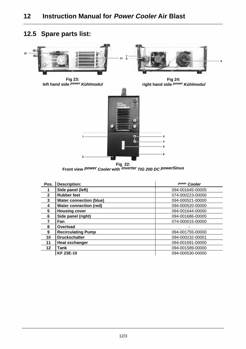
12.5 Spare parts list:
10
11
Fig 23:left hand side power Kühlmodul
7878
9
Fig 24:right hand side power Kühlmodul
Fig 22:Front view power Cooler with inverter TIG 200 DC powerSinus
Pos. Description: power Cooler1 Side panel (left) 094-001645-000052 Rubber feet 074-000223-000003 Water connection (blue) 094-000521-000004 Water connection (red) 094-000520-000005 Housing cover 094-001644-000006 Side panel (right) 094-001686-000057 Fan 074-000015-000008 Overload -9 Recirculating Pump 094-001755-0000010 Druckschalter 094-000232-0000111 Heat exchanger 094-001691-0000012 Tank 094-001589-00000
KF 23E-10 094-000530-00000
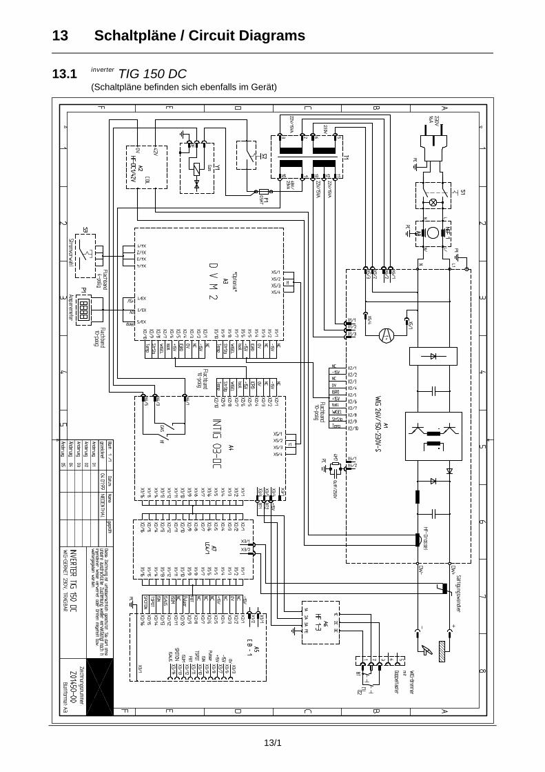
13 Schaltpläne / Circuit Diagrams
13/1
13.1 inverter TIG 150 DC(Schaltpläne befinden sich ebenfalls im Gerät)

13 Schaltpläne / Circuit Diagrams
13/2
13.2 inverter TIG 200 DC powerSinus
13 Schaltpläne / Circuit Diagrams
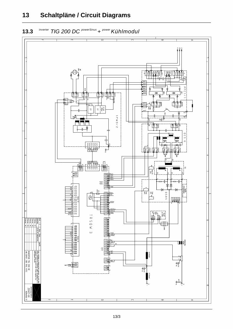
13/3
13.3 inverter TIG 200 DC powerSinus + power Kühlmodul
13 Schaltpläne / Circuit Diagrams
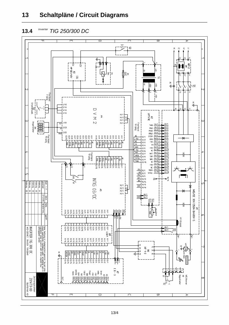
13/4
13.4 inverter TIG 250/300 DC