Embed Size (px)
Citation preview
THz Frequency Selective Surface Filters for Earth ObservationRemote Sensing Instruments
Dickie, R., Cahill, R., Fusco, V., Gamble, H., & Mitchell, N. (2011). THz Frequency Selective Surface Filters forEarth Observation Remote Sensing Instruments. IEEE Transactions on Terahertz Science and Technology,1(2), 450-461. [5750080]. https://doi.org/10.1109/TTHZ.2011.2129470
Published in:IEEE Transactions on Terahertz Science and Technology
Queen's University Belfast - Research Portal:Link to publication record in Queen's University Belfast Research Portal
General rightsCopyright for the publications made accessible via the Queen's University Belfast Research Portal is retained by the author(s) and / or othercopyright owners and it is a condition of accessing these publications that users recognise and abide by the legal requirements associatedwith these rights.
Take down policyThe Research Portal is Queen's institutional repository that provides access to Queen's research output. Every effort has been made toensure that content in the Research Portal does not infringe any person's rights, or applicable UK laws. If you discover content in theResearch Portal that you believe breaches copyright or violates any law, please contact [email protected].
Download date:11. Apr. 2020
This article has been accepted for inclusion in a future issue of this journal. Content is final as presented, with the exception of pagination.
IEEE TRANSACTIONS ON TERAHERTZ SCIENCE AND TECHNOLOGY 1
THz Frequency Selective Surface Filters for EarthObservation Remote Sensing Instruments
Raymond Dickie, Robert Cahill, Senior Member, IEEE, Vincent Fusco, Fellow, IEEE, Harold S. Gamble, andNeil Mitchell, Senior Member, IEEE
Abstract—The purpose of this paper is to review recent develop-ments in the design and fabrication of Frequency Selective Sur-faces (FSS) which operate above 300 GHz. These structures actas free space electromagnetic filters and as such provide passiveremote sensing instruments with multispectral capability by sep-arating the scene radiation into separate frequency channels. Sig-nificant advances in computational electromagnetics, precision mi-cromachining technology and metrology have been employed tocreate state of the art FSS which enable high sensitivity receiversto detect weak molecular emissions at THz wavelengths. This newclass of quasi-optical filter exhibits an insertion loss 0.3 dB at700 GHz and can be designed to operate independently of the po-larization of the incident signals at oblique incidence. The paperconcludes with a brief overview of two major technical advanceswhich will greatly extend the potential applications of THz FSS.
Index Terms—Frequency selective surfaces (FSS), liquidcrystals, mesh filters, micromachined structures, polarizationconverter, quasi-optical technology, THz filters.
I. INTRODUCTION
O VER the past decade major advances have been made inspace borne THz instrument technology, primarily to ad-
dress the need to study the processes driving the climate, andto monitor the changes and provide a health check on the envi-ronment in which we live [1]. This requires complex imaging ofclouds [2] and spectroscopic characterization of carbon dioxideand other greenhouse gases in the Earth’s atmosphere using re-mote sensing instruments which operate over wide bandwidthscovering the thermal emission lines of the gases being observed[3]. To satisfy satellite payload constraints on cost, mass and en-ergy consumption, passive Earth observation radiometers tradi-tionally employ a single mechanically scanned aperture antennato collect the radiation. Frequency selective surface (FSS) de-multiplexing elements are a key enabling technology for theseadvanced instruments and are used in the quasi-optical receiverto spectrally separate the signals that are collected by the scan-ning antenna [3]. The key technology challenge is to ensure that
Manuscript received January 28, 2011; revised March 04, 2011; acceptedMarch 04, 2011. This work was supported in part by ESA under Contract19854/06/NL/JA, EPSRC under Grant EP/E01707X1 and Grant EP/S13828/01,by EADS Astrium UK, CEOI (www.ceoi.ac.uk), and by the European Re-gional Development Fund under the European Sustainable CompetitivenessProgramme for Northern Ireland.
The authors are with The Institute of Electronics, Communications and In-formation Technology, The Queen’s University of Belfast, Belfast BT3 9DT,Northern Ireland, U.K. (e-mail: [email protected]).
Color versions of one or more of the figures in this paper are available onlineat http://ieeexplore.ieee.org.
Digital Object Identifier 10.1109/TTHZ.2011.2129470
the FSS exhibit very low signal band insertion loss and simulta-neously meet the conflicting requirement for high isolation be-tween adjacent frequency bands. This is required to minimizethe overall noise performance of the instrument and therebyachieve high receiver sensitivity which is necessary to detectweak molecular emissions at THz wavelengths. In addition theFSS must also exhibit high performance at large incident an-gles to reduce the footprint of the feed train and moreover thestructure should be sufficiently robust to withstand the launchforces of the space vehicle and operate without failure in theharsh thermal environment.
The purpose of this paper is to acquaint the reader withthe principle application of this technology and to present anoverview of a multidisciplinary research project at Queen’sUniversity Belfast (QUB) which has exploited state of theart developments in silicon microtechnology to create a newclass of substrateless FSS that satisfies the electromagneticrequirements for remote sensing instruments that will enterservice in the 21st century. These FSS will operate at 45incidence and exhibit very high mechanical strength andsuitable CTE properties. In addition to the use of new mi-cromachining technology, innovative electromagnetic designstrategies and measurement techniques have been employed tocreate quasi-optical filters which can separate either linear orsimultaneously separate vertical and horizontal polarized com-ponents of naturally occurring thermal emissions with spectralefficiencies exceeding 93% at frequencies up to 700 GHz. Theelectromagnetic performance exhibited by this new class ofFSS is presented for the MARSCHALS airborne limbsounder(294–380 GHz) [4], [5], European Space Agency (ESA) dualpolarization FSS technology demonstrator (316.5–358.5 GHz)[6] and the Microwave Imager (MWI) instrument (113–670.7GHz) which is currently being developed for the European PostEPS mission [2]. This paper concludes with a brief overviewof two new innovative THz FSS structures which are currentlybeing developed at QUB. One FSS variant provides conversionfrom linear to circular polarization whereas the other structureexhibits electronic shutter operation by exploiting the dielectricanisotropy property of nematic state liquid crystals.
II. FSS DESIGN AND SPECTRAL PERFORMANCE
A. Evolution of FSS Architecture
Radiometric remote sensing instruments in service before2000 were generally designed to collect data using a single aper-ture antenna and drilled plate waveguide filters were deployedin the quasi-optical feed train to separate the signals and directthese to the spatial location of the individual channel mixer
2156-342X/$26.00 © 2011 IEEE
This article has been accepted for inclusion in a future issue of this journal. Content is final as presented, with the exception of pagination.
2 IEEE TRANSACTIONS ON TERAHERTZ SCIENCE AND TECHNOLOGY
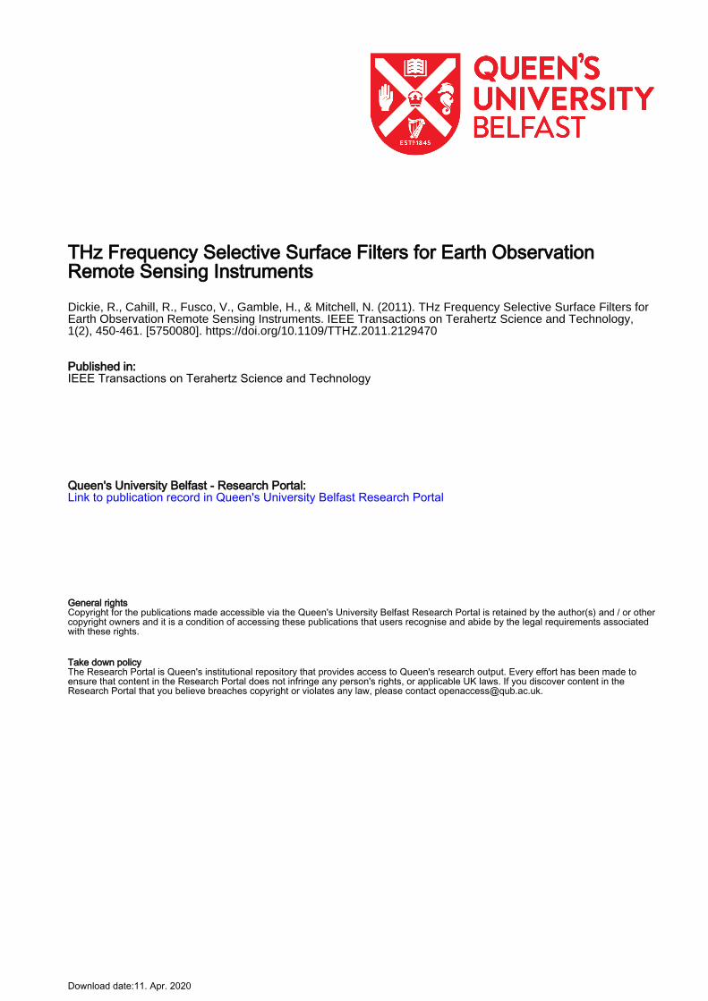
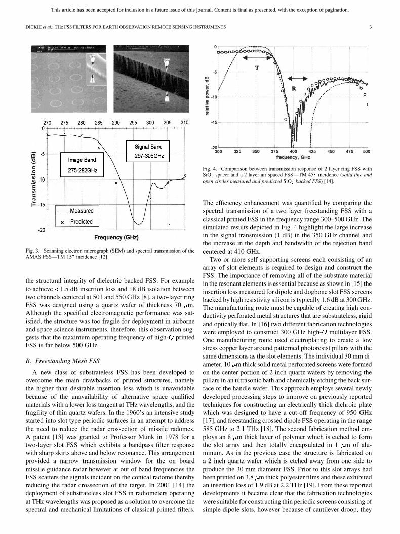
Fig. 1. 10 mm diameter 600 GHz waveguide FSS—TM 15 [8], [9].
detectors. For example the ’Advanced Microwave SoundingUnits (AMSU-B) which were launched on NOAA-15, 16, and17 satellites between 1998–2002, used two waveguide arrayFSS to separate three signals bands centered at 89, 150, and183 GHz [7]. The structures were fabricated using a computercontrolled mill to precision drill an aluminum disk to thenominal dimensions of the two close packed arrays. Althoughthis type of FSS is mechanically robust the spectral response isvery sensitive to angle of incidence, the insertion loss can behigh and the structures lacks design flexibility because the filteronly provides high pass mode operation. Nevertheless until thebeginning of the millennium this was the only space qualifiedmethod available to construct compact devices for spatiallyseparating signals at millimeter wavelengths. To address theneed to move to THz wavelengths in which there are resonancesof ClO, BrO, HCl, and NO, an FSS demonstrator was designedto operate at 15 incidence and allow transmission of 540–660GHz radiation and reject signals below 500 GHz. Fig. 1 depictsa photograph of the structure and the predicted and measuredspectral response where it is shown that the transmission inser-tion loss is in the range 0.5–2.0 dB [8], [9].
Post AMSU-B a more versatile architecture consisting ofprinted FSS became available. These had the advantage thatthey could easily be designed to operate at large incident angles,in high pass, low pass and bandpass modes [10]. Furthermoreconventional photolithographic techniques similar to thoseused in the semiconductor wafer industry were employed toprint the periodic structures which generally consist of stronglyshaped metal elements. The substrate choice for space scienceinstruments is SiO since this material is space qualified and the
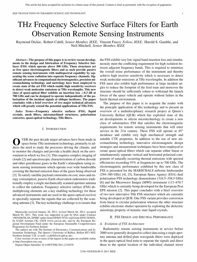
Fig. 2. MARSCHALS quasi-optical feed train—courtesy of STFC.
electrical design parameters are precisely known [11]. Struc-tures of this type are employed in the Millimetre-wave AirborneReceiver for Spectroscopic CHaracterisation of AtmosphericLimb-Sounding (MARSCHALS) radiometer which is currentlybeing developed by a European consortium led by RutherfordAppleton Laboratories in the U.K. [4]. The main objective ofthe instrument is to measure vertical profiles of ozone, watervapor, carbon dioxide and other gaseous components in theupper troposphere. Three printed FSS are deployed in thequasi-optical feed train, two function as image band rejectionfilters which separate the bands 316–326 GHz/350–359 GHz,342–349 GHz/373–380 GHz, and the third FSS is used toprovide demultiplexing of the channels 342–380 GHz/294–306GHz. A photograph of the instrument and the location of thethree filters are depicted in Fig. 2. The FSS were constructedfrom ring element arrays printed on opposite sides of quartzwafers of thickness in the range 100–130 m. The structuresallow transmission of radiation with a maximum insertionloss 1.0–1.5 dB in the TM 45 plane and for all three FSS theimage/channel band rejection is better than 10 dB. The filter ar-chitecture and spectral performance are similar to a FSS whichwas designed to separate the signal band 297–304.5 GHz fromthe image band 275–282 GHz in the Advanced MicrowaveAtmospheric Sounder (AMAS) [12]. This instrument wasdeveloped by Rutherford Appleton Laboratories under contractto Dornier GmbH. An SEM and a plot comparing the mea-sured and simulated spectral response are depicted in Fig. 3.The MARSCHALS and AMAS radiometers are designed toseparate signal channels which are very closely spaced, withedge of band frequency ratios in the range 1.053:1–1.12:1.For this reason the structures require two periodic screens toachieve the fast transmission roll off which is required belowresonance [9]. However the insertion loss of multilayer printedFSS is inversely proportional to the signal channel spacing[11] and therefore this can compromise the performance of theinstrument. Moreover, another major practical consideration is
This article has been accepted for inclusion in a future issue of this journal. Content is final as presented, with the exception of pagination.
DICKIE et al.: THz FSS FILTERS FOR EARTH OBSERVATION REMOTE SENSING INSTRUMENTS 3
Fig. 3. Scanning electron micrograph (SEM) and spectral transmission of theAMAS FSS—TM 15 incidence [12].
the structural integrity of dielectric backed FSS. For exampleto achieve 1.5 dB insertion loss and 18 dB isolation betweentwo channels centered at 501 and 550 GHz [8], a two-layer ringFSS was designed using a quartz wafer of thickness 70 m.Although the specified electromagnetic performance was sat-isfied, the structure was too fragile for deployment in airborneand space science instruments, therefore, this observation sug-gests that the maximum operating frequency of high- printedFSS is far below 500 GHz.
B. Freestanding Mesh FSS
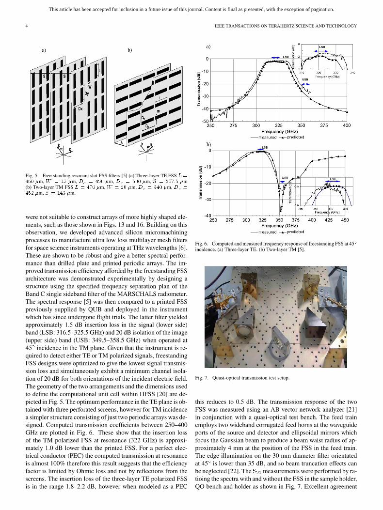
A new class of substrateless FSS has been developed toovercome the main drawbacks of printed structures, namelythe higher than desirable insertion loss which is unavoidablebecause of the unavailability of alternative space qualifiedmaterials with a lower loss tangent at THz wavelengths, and thefragility of thin quartz wafers. In the 1960’s an intensive studystarted into slot type periodic surfaces in an attempt to addressthe need to reduce the radar crossection of missile radomes.A patent [13] was granted to Professor Munk in 1978 for atwo-layer slot FSS which exhibits a bandpass filter responsewith sharp skirts above and below resonance. This arrangementprovided a narrow transmission window for the on boardmissile guidance radar however at out of band frequencies theFSS scatters the signals incident on the conical radome therebyreducing the radar crossection of the target. In 2001 [14] thedeployment of substrateless slot FSS in radiometers operatingat THz wavelengths was proposed as a solution to overcome thespectral and mechanical limitations of classical printed filters.
Fig. 4. Comparison between transmission response of 2 layer ring FSS withSiO spacer and a 2 layer air spaced FSS—TM 45 incidence (solid line andopen circles measured and predicted SiO backed FSS) [14].
The efficiency enhancement was quantified by comparing thespectral transmission of a two layer freestanding FSS with aclassical printed FSS in the frequency range 300–500 GHz. Thesimulated results depicted in Fig. 4 highlight the large increasein the signal transmission (1 dB) in the 350 GHz channel andthe increase in the depth and bandwidth of the rejection bandcentered at 410 GHz.
Two or more self supporting screens each consisting of anarray of slot elements is required to design and construct theFSS. The importance of removing all of the substrate materialin the resonant elements is essential because as shown in [15] theinsertion loss measured for dipole and dogbone slot FSS screensbacked by high resistivity silicon is typically 1.6 dB at 300 GHz.The manufacturing route must be capable of creating high con-ductivity perforated metal structures that are substrateless, rigidand optically flat. In [16] two different fabrication technologieswere employed to construct 300 GHz high- multilayer FSS.One manufacturing route used electroplating to create a lowstress copper layer around patterned photoresist pillars with thesame dimensions as the slot elements. The individual 30 mm di-ameter, 10 m thick solid metal perforated screens were formedon the center portion of 2 inch quartz wafers by removing thepillars in an ultrasonic bath and chemically etching the back sur-face of the handle wafer. This approach employs several newlydeveloped processing steps to improve on previously reportedtechniques for constructing an electrically thick dichroic platewhich was designed to have a cut-off frequency of 950 GHz[17], and freestanding crossed dipole FSS operating in the range585 GHz to 2.1 THz [18]. The second fabrication method em-ploys an 8 m thick layer of polymer which is etched to formthe slot array and then totally encapsulated in 1 m of alu-minum. As in the previous case the structure is fabricated ona 2 inch quartz wafer which is etched away from one side toproduce the 30 mm diameter FSS. Prior to this slot arrays hadbeen printed on 3.8 m thick polyester films and these exhibitedan insertion loss of 1.9 dB at 2.2 THz [19]. From these reporteddevelopments it became clear that the fabrication technologieswere suitable for constructing thin periodic screens consisting ofsimple dipole slots, however because of cantilever droop, they
This article has been accepted for inclusion in a future issue of this journal. Content is final as presented, with the exception of pagination.
4 IEEE TRANSACTIONS ON TERAHERTZ SCIENCE AND TECHNOLOGY
Fig. 5. Free standing resonant slot FSS filters [5] (a) Three-layer TE FSS � �
��� �m, � � �� �m, � � ��� �m, � � ��� �m, � � ���� �m(b) Two-layer TM FSS � � �� �m, � � � �m, � � ��� �m, � �
�� �m, � � ��� �m.
were not suitable to construct arrays of more highly shaped ele-ments, such as those shown in Figs. 13 and 16. Building on thisobservation, we developed advanced silicon micromachiningprocesses to manufacture ultra low loss multilayer mesh filtersfor space science instruments operating at THz wavelengths [6].These are shown to be robust and give a better spectral perfor-mance than drilled plate and printed periodic arrays. The im-proved transmission efficiency afforded by the freestanding FSSarchitecture was demonstrated experimentally by designing astructure using the specified frequency separation plan of theBand C single sideband filter of the MARSCHALS radiometer.The spectral response [5] was then compared to a printed FSSpreviously supplied by QUB and deployed in the instrumentwhich has since undergone flight trials. The latter filter yieldedapproximately 1.5 dB insertion loss in the signal (lower side)band (LSB: 316.5–325.5 GHz) and 20 dB isolation of the image(upper side) band (USB: 349.5–358.5 GHz) when operated at45 incidence in the TM plane. Given that the instrument is re-quired to detect either TE or TM polarized signals, freestandingFSS designs were optimized to give the lowest signal transmis-sion loss and simultaneously exhibit a minimum channel isola-tion of 20 dB for both orientations of the incident electric field.The geometry of the two arrangements and the dimensions usedto define the computational unit cell within HFSS [20] are de-picted in Fig. 5. The optimum performance in the TE plane is ob-tained with three perforated screens, however for TM incidencea simpler structure consisting of just two periodic arrays was de-signed. Computed transmission coefficients between 250–400GHz are plotted in Fig. 6. These show that the insertion lossof the TM polarized FSS at resonance (322 GHz) is approxi-mately 1.0 dB lower than the printed FSS. For a perfect elec-trical conductor (PEC) the computed transmission at resonanceis almost 100% therefore this result suggests that the efficiencyfactor is limited by Ohmic loss and not by reflections from thescreens. The insertion loss of the three-layer TE polarized FSSis in the range 1.8–2.2 dB, however when modeled as a PEC
Fig. 6. Computed and measured frequency response of freestanding FSS at 45incidence. (a) Three-layer TE. (b) Two-layer TM [5].
Fig. 7. Quasi-optical transmission test setup.
this reduces to 0.5 dB. The transmission response of the twoFSS was measured using an AB vector network analyzer [21]in conjunction with a quasi-optical test bench. The feed trainemploys two wideband corrugated feed horns at the waveguideports of the source and detector and ellipsoidal mirrors whichfocus the Gaussian beam to produce a beam waist radius of ap-proximately 4 mm at the position of the FSS in the feed train.The edge illumination on the 30 mm diameter filter orientatedat 45 is lower than 35 dB, and so beam truncation effects canbe neglected [22]. The measurements were performed by ra-tioing the spectra with and without the FSS in the sample holder,QO bench and holder as shown in Fig. 7. Excellent agreement
This article has been accepted for inclusion in a future issue of this journal. Content is final as presented, with the exception of pagination.
DICKIE et al.: THz FSS FILTERS FOR EARTH OBSERVATION REMOTE SENSING INSTRUMENTS 5
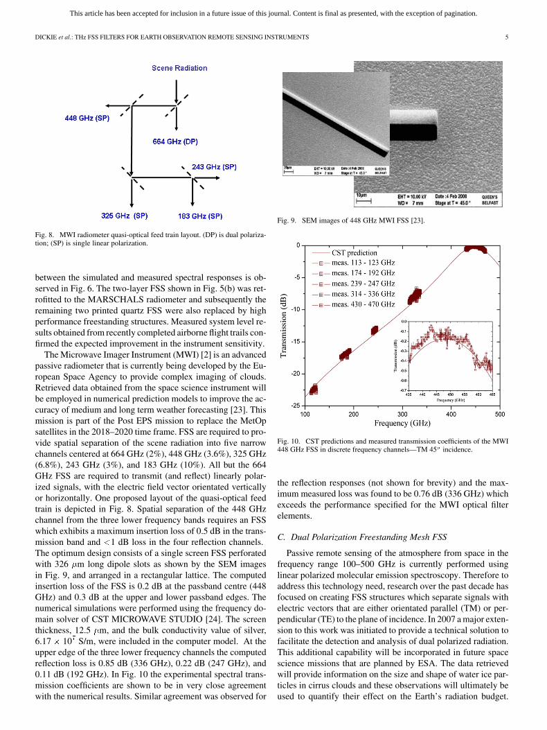
Fig. 8. MWI radiometer quasi-optical feed train layout. (DP) is dual polariza-tion; (SP) is single linear polarization.
between the simulated and measured spectral responses is ob-served in Fig. 6. The two-layer FSS shown in Fig. 5(b) was ret-rofitted to the MARSCHALS radiometer and subsequently theremaining two printed quartz FSS were also replaced by highperformance freestanding structures. Measured system level re-sults obtained from recently completed airborne flight trails con-firmed the expected improvement in the instrument sensitivity.
The Microwave Imager Instrument (MWI) [2] is an advancedpassive radiometer that is currently being developed by the Eu-ropean Space Agency to provide complex imaging of clouds.Retrieved data obtained from the space science instrument willbe employed in numerical prediction models to improve the ac-curacy of medium and long term weather forecasting [23]. Thismission is part of the Post EPS mission to replace the MetOpsatellites in the 2018–2020 time frame. FSS are required to pro-vide spatial separation of the scene radiation into five narrowchannels centered at 664 GHz (2%), 448 GHz (3.6%), 325 GHz(6.8%), 243 GHz (3%), and 183 GHz (10%). All but the 664GHz FSS are required to transmit (and reflect) linearly polar-ized signals, with the electric field vector orientated verticallyor horizontally. One proposed layout of the quasi-optical feedtrain is depicted in Fig. 8. Spatial separation of the 448 GHzchannel from the three lower frequency bands requires an FSSwhich exhibits a maximum insertion loss of 0.5 dB in the trans-mission band and 1 dB loss in the four reflection channels.The optimum design consists of a single screen FSS perforatedwith 326 m long dipole slots as shown by the SEM imagesin Fig. 9, and arranged in a rectangular lattice. The computedinsertion loss of the FSS is 0.2 dB at the passband centre (448GHz) and 0.3 dB at the upper and lower passband edges. Thenumerical simulations were performed using the frequency do-main solver of CST MICROWAVE STUDIO [24]. The screenthickness, 12.5 m, and the bulk conductivity value of silver,6.17 10 S/m, were included in the computer model. At theupper edge of the three lower frequency channels the computedreflection loss is 0.85 dB (336 GHz), 0.22 dB (247 GHz), and0.11 dB (192 GHz). In Fig. 10 the experimental spectral trans-mission coefficients are shown to be in very close agreementwith the numerical results. Similar agreement was observed for
Fig. 9. SEM images of 448 GHz MWI FSS [23].
Fig. 10. CST predictions and measured transmission coefficients of the MWI448 GHz FSS in discrete frequency channels—TM 45 incidence.
the reflection responses (not shown for brevity) and the max-imum measured loss was found to be 0.76 dB (336 GHz) whichexceeds the performance specified for the MWI optical filterelements.
C. Dual Polarization Freestanding Mesh FSS
Passive remote sensing of the atmosphere from space in thefrequency range 100–500 GHz is currently performed usinglinear polarized molecular emission spectroscopy. Therefore toaddress this technology need, research over the past decade hasfocused on creating FSS structures which separate signals withelectric vectors that are either orientated parallel (TM) or per-pendicular (TE) to the plane of incidence. In 2007 a major exten-sion to this work was initiated to provide a technical solution tofacilitate the detection and analysis of dual polarized radiation.This additional capability will be incorporated in future spacescience missions that are planned by ESA. The data retrievedwill provide information on the size and shape of water ice par-ticles in cirrus clouds and these observations will ultimately beused to quantify their effect on the Earth’s radiation budget.
This article has been accepted for inclusion in a future issue of this journal. Content is final as presented, with the exception of pagination.
6 IEEE TRANSACTIONS ON TERAHERTZ SCIENCE AND TECHNOLOGY
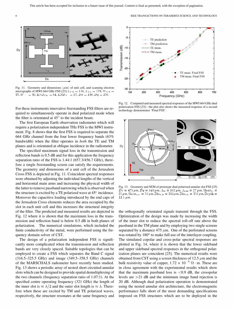
Fig. 11. Geometry and dimensions ��m� of unit cell, and scanning electronmicrographs of MWI 664 GHz FSS [23] � � ���, � � ���, � ���,� � , �� � ��, �� � ��,�� � �,�� � ��.
For these instruments innovative freestanding FSS filters are re-quired to simultaneously operate in dual polarized mode whenthe filter is orientated at 45 to the incident beam.
The first European Earth observation radiometer which willrequire a polarization independent THz FSS is the MWI instru-ment. Fig. 8 shows that the first FSS is required to separate the664 GHz channel from the four lower frequency bands (63%bandwidth) when the filter operates in both the TE and TMplanes and is orientated at oblique incidence in the radiometer.
The specified maximum signal loss in the transmission andreflection bands is 0.5 dB and for this application the frequencyseparation ratio of the FSS is 1.44:1 (657.3/456.7 GHz), there-fore a single freestanding screen can satisfy the requirements.The geometry and dimensions of a unit cell of the JerusalemCross FSS is depicted in Fig. 11. Coincident spectral responseswere obtained by adjusting the individual lengths of the verticaland horizontal main arms and increasing the physical width ofthe latter to remove passband narrowing which is observed whenthe structure is excited by a TE polarized wave at 45 incidence.Moreover the capacitive loading introduced by the end caps ofthe Jerusalem Cross elements reduces the area occupied by theslot in each unit cell and this increases the structural integrityof the filter. The predicted and measured results are depicted inFig. 12 where it is shown that the maximum loss in the trans-mission and reflection band is below 0.5 dB in both planes ofpolarization. The numerical simulations, which included thefinite conductivity of the metal, were performed using the fre-quency domain solver of CST.
The design of a polarization independent FSS is signifi-cantly more complicated when the transmission and reflectionbands are very closely spaced. Suitable topologies that can beemployed to create a FSS which separates the Band C signal(316.5–325.5 GHz) and image (349.5–358.5 GHz) channelsof the MARSCHALS radiometer have recently been studied.Fig. 13 shows a periodic array of nested short circuited annularslots which can be designed to provide spatial demultiplexing ofthe two channels (frequency separation ratio of 1.07:1). At thespecified centre operating frequency (321 GHz) the length ofthe inner slot is and the outer slot length is . There-fore when these are excited by TM and TE polarized waves,respectively, the structure resonates at the same frequency and
Fig. 12. Computed and measured spectral responses of the MWI 664 GHz dualpolarization FSS [23]—the plot also shows the measured response of a secondtechnology demonstrator ‘Final FSS’.
Fig. 13. Geometry and SEM of prototype dual polarized annular slot FSS [25]�� � ��� �m, �� � �� �m, � � �� �m, � � �� �m, ����� ����m,����� � ���m, �� � ���m, �� � ���m, ���� ����� �m.
the orthogonally orientated signals transmit through the FSS.Optimization of the design was made by increasing the widthof the inner slot to reduce the spectral roll-off rate above thepassband in the TM plane and by employing two single screensseparated by a distance 475 m. One of the perforated screenswas rotated by 180 to make full use of the interlayer coupling.The simulated copolar and cross-polar spectral responses areplotted in Fig. 14, where it is shown that the lower sidebandand upper sideband spectral responses in the orthogonal polar-ization planes are coincident [25]. The numerical results wereobtained from CST using a screen thickness of 12.5 m and thebulk resistivity value of copper, 1.72 10 m. These arein close agreement with the experimental results which showthat the maximum passband loss is 0.9 dB, the crosspolarlevels are 21 dB and the minimum image band rejection is20 dB. Although dual polarization operation is demonstratedusing the nested annular slot architecture, the electromagneticperformance falls short of the most demanding specificationsimposed on FSS structures which are to be deployed in the
This article has been accepted for inclusion in a future issue of this journal. Content is final as presented, with the exception of pagination.
DICKIE et al.: THz FSS FILTERS FOR EARTH OBSERVATION REMOTE SENSING INSTRUMENTS 7
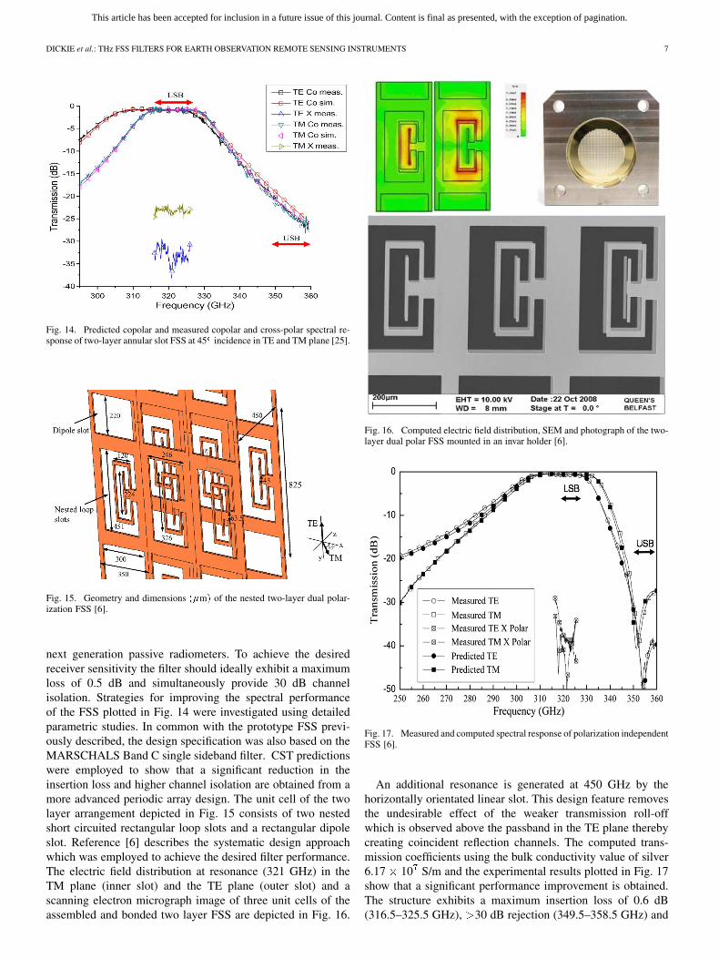
Fig. 14. Predicted copolar and measured copolar and cross-polar spectral re-sponse of two-layer annular slot FSS at 45 incidence in TE and TM plane [25].
Fig. 15. Geometry and dimensions ��m� of the nested two-layer dual polar-ization FSS [6].
next generation passive radiometers. To achieve the desiredreceiver sensitivity the filter should ideally exhibit a maximumloss of 0.5 dB and simultaneously provide 30 dB channelisolation. Strategies for improving the spectral performanceof the FSS plotted in Fig. 14 were investigated using detailedparametric studies. In common with the prototype FSS previ-ously described, the design specification was also based on theMARSCHALS Band C single sideband filter. CST predictionswere employed to show that a significant reduction in theinsertion loss and higher channel isolation are obtained from amore advanced periodic array design. The unit cell of the twolayer arrangement depicted in Fig. 15 consists of two nestedshort circuited rectangular loop slots and a rectangular dipoleslot. Reference [6] describes the systematic design approachwhich was employed to achieve the desired filter performance.The electric field distribution at resonance (321 GHz) in theTM plane (inner slot) and the TE plane (outer slot) and ascanning electron micrograph image of three unit cells of theassembled and bonded two layer FSS are depicted in Fig. 16.
Fig. 16. Computed electric field distribution, SEM and photograph of the two-layer dual polar FSS mounted in an invar holder [6].
Fig. 17. Measured and computed spectral response of polarization independentFSS [6].
An additional resonance is generated at 450 GHz by thehorizontally orientated linear slot. This design feature removesthe undesirable effect of the weaker transmission roll-offwhich is observed above the passband in the TE plane therebycreating coincident reflection channels. The computed trans-mission coefficients using the bulk conductivity value of silver6.17 10 S/m and the experimental results plotted in Fig. 17show that a significant performance improvement is obtained.The structure exhibits a maximum insertion loss of 0.6 dB(316.5–325.5 GHz), 30 dB rejection (349.5–358.5 GHz) and
This article has been accepted for inclusion in a future issue of this journal. Content is final as presented, with the exception of pagination.
8 IEEE TRANSACTIONS ON TERAHERTZ SCIENCE AND TECHNOLOGY
Fig. 18. Key processing steps used to construct one single FSS layer.
cross-polar levels below 25 dB simultaneously for TE andTM polarizations at 45 incidence.
III. FABRICATION AND SPACE QUALIFICATION
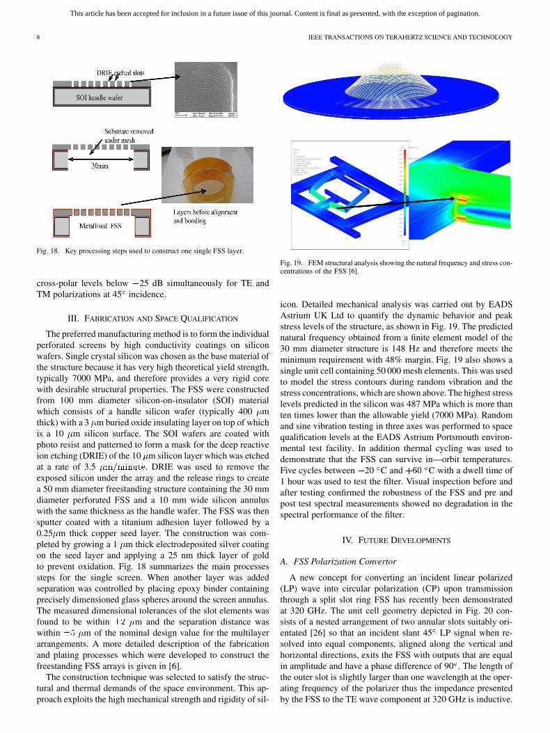
The preferred manufacturing method is to form the individualperforated screens by high conductivity coatings on siliconwafers. Single crystal silicon was chosen as the base material ofthe structure because it has very high theoretical yield strength,typically 7000 MPa, and therefore provides a very rigid corewith desirable structural properties. The FSS were constructedfrom 100 mm diameter silicon-on-insulator (SOI) materialwhich consists of a handle silicon wafer (typically 400 mthick) with a 3 m buried oxide insulating layer on top of whichis a 10 m silicon surface. The SOI wafers are coated withphoto resist and patterned to form a mask for the deep reactiveion etching (DRIE) of the 10 m silicon layer which was etchedat a rate of 3.5 . DRIE was used to remove theexposed silicon under the array and the release rings to createa 50 mm diameter freestanding structure containing the 30 mmdiameter perforated FSS and a 10 mm wide silicon annuluswith the same thickness as the handle wafer. The FSS was thensputter coated with a titanium adhesion layer followed by a0.25 m thick copper seed layer. The construction was com-pleted by growing a 1 m thick electrodeposited silver coatingon the seed layer and applying a 25 nm thick layer of goldto prevent oxidation. Fig. 18 summarizes the main processessteps for the single screen. When another layer was addedseparation was controlled by placing epoxy binder containingprecisely dimensioned glass spheres around the screen annulus.The measured dimensional tolerances of the slot elements wasfound to be within m and the separation distance waswithin m of the nominal design value for the multilayerarrangements. A more detailed description of the fabricationand plating processes which were developed to construct thefreestanding FSS arrays is given in [6].
The construction technique was selected to satisfy the struc-tural and thermal demands of the space environment. This ap-proach exploits the high mechanical strength and rigidity of sil-
Fig. 19. FEM structural analysis showing the natural frequency and stress con-centrations of the FSS [6].
icon. Detailed mechanical analysis was carried out by EADSAstrium UK Ltd to quantify the dynamic behavior and peakstress levels of the structure, as shown in Fig. 19. The predictednatural frequency obtained from a finite element model of the30 mm diameter structure is 148 Hz and therefore meets theminimum requirement with 48% margin. Fig. 19 also shows asingle unit cell containing 50 000 mesh elements. This was usedto model the stress contours during random vibration and thestress concentrations, which are shown above. The highest stresslevels predicted in the silicon was 487 MPa which is more thanten times lower than the allowable yield (7000 MPa). Randomand sine vibration testing in three axes was performed to spacequalification levels at the EADS Astrium Portsmouth environ-mental test facility. In addition thermal cycling was used todemonstrate that the FSS can survive in—orbit temperatures.Five cycles between 20 C and C with a dwell time of1 hour was used to test the filter. Visual inspection before andafter testing confirmed the robustness of the FSS and pre andpost test spectral measurements showed no degradation in thespectral performance of the filter.
IV. FUTURE DEVELOPMENTS
A. FSS Polarization Convertor
A new concept for converting an incident linear polarized(LP) wave into circular polarization (CP) upon transmissionthrough a split slot ring FSS has recently been demonstratedat 320 GHz. The unit cell geometry depicted in Fig. 20 con-sists of a nested arrangement of two annular slots suitably ori-entated [26] so that an incident slant 45 LP signal when re-solved into equal components, aligned along the vertical andhorizontal directions, exits the FSS with outputs that are equalin amplitude and have a phase difference of 90 . The length ofthe outer slot is slightly larger than one wavelength at the oper-ating frequency of the polarizer thus the impedance presentedby the FSS to the TE wave component at 320 GHz is inductive.
This article has been accepted for inclusion in a future issue of this journal. Content is final as presented, with the exception of pagination.
DICKIE et al.: THz FSS FILTERS FOR EARTH OBSERVATION REMOTE SENSING INSTRUMENTS 9
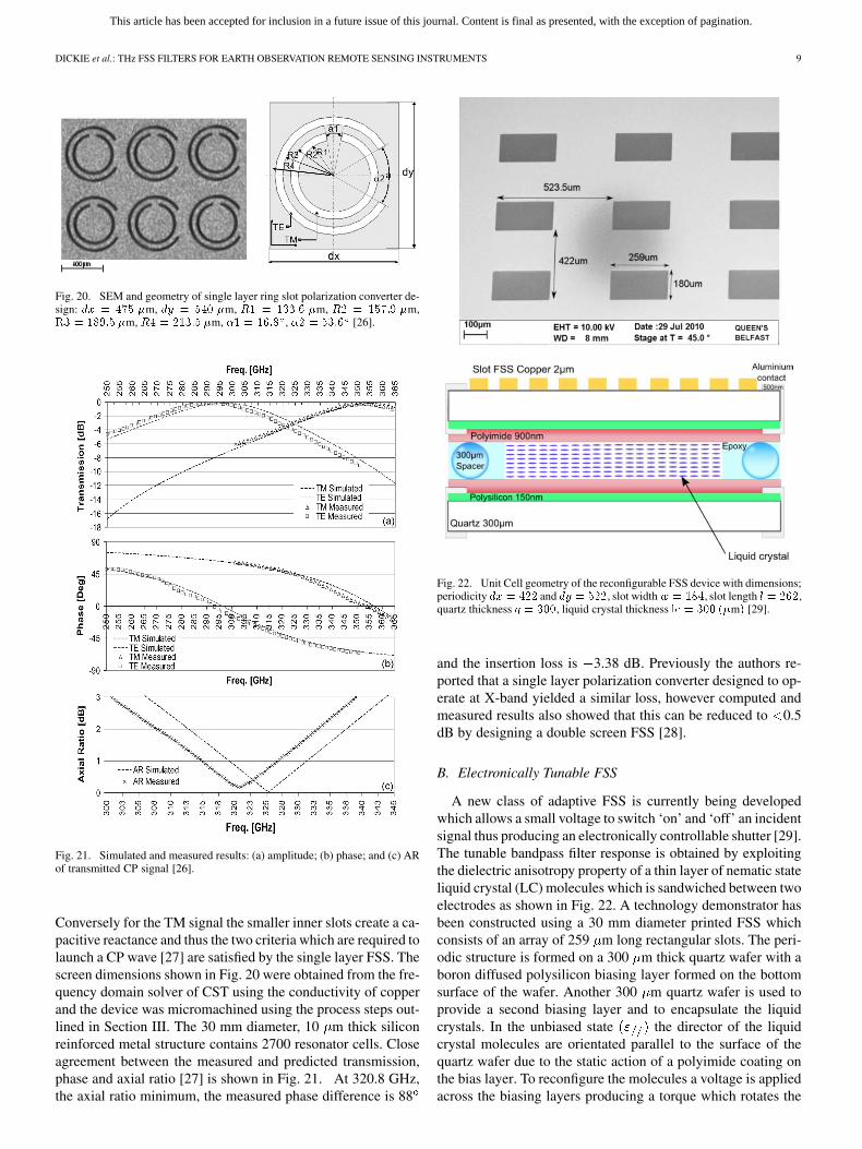
Fig. 20. SEM and geometry of single layer ring slot polarization converter de-sign: �� � ��� �m, �� � ��� �m, �� � ����� �m, � � ���� �m,�� � ���� �m, �� � ���� �m, �� � ���� , � � ���� [26].
Fig. 21. Simulated and measured results: (a) amplitude; (b) phase; and (c) ARof transmitted CP signal [26].
Conversely for the TM signal the smaller inner slots create a ca-pacitive reactance and thus the two criteria which are required tolaunch a CP wave [27] are satisfied by the single layer FSS. Thescreen dimensions shown in Fig. 20 were obtained from the fre-quency domain solver of CST using the conductivity of copperand the device was micromachined using the process steps out-lined in Section III. The 30 mm diameter, 10 m thick siliconreinforced metal structure contains 2700 resonator cells. Closeagreement between the measured and predicted transmission,phase and axial ratio [27] is shown in Fig. 21. At 320.8 GHz,the axial ratio minimum, the measured phase difference is 88
Fig. 22. Unit Cell geometry of the reconfigurable FSS device with dimensions;periodicity �� � � and �� � �, slot width� � ���, slot length � �,quartz thickness � ���, liquid crystal thickness � � ��� ��m� [29].
and the insertion loss is 3.38 dB. Previously the authors re-ported that a single layer polarization converter designed to op-erate at X-band yielded a similar loss, however computed andmeasured results also showed that this can be reduced to 0.5dB by designing a double screen FSS [28].
B. Electronically Tunable FSS
A new class of adaptive FSS is currently being developedwhich allows a small voltage to switch ‘on’ and ‘off’ an incidentsignal thus producing an electronically controllable shutter [29].The tunable bandpass filter response is obtained by exploitingthe dielectric anisotropy property of a thin layer of nematic stateliquid crystal (LC) molecules which is sandwiched between twoelectrodes as shown in Fig. 22. A technology demonstrator hasbeen constructed using a 30 mm diameter printed FSS whichconsists of an array of 259 m long rectangular slots. The peri-odic structure is formed on a 300 m thick quartz wafer with aboron diffused polysilicon biasing layer formed on the bottomsurface of the wafer. Another 300 m quartz wafer is used toprovide a second biasing layer and to encapsulate the liquidcrystals. In the unbiased state the director of the liquidcrystal molecules are orientated parallel to the surface of thequartz wafer due to the static action of a polyimide coating onthe bias layer. To reconfigure the molecules a voltage is appliedacross the biasing layers producing a torque which rotates the
This article has been accepted for inclusion in a future issue of this journal. Content is final as presented, with the exception of pagination.
10 IEEE TRANSACTIONS ON TERAHERTZ SCIENCE AND TECHNOLOGY
Fig. 23. Measured and predicted spectral response of experimental electroni-cally reconfigurable liquid crystal based FSS [29].
molecules perpendicular to surfaces. This changes the permit-tivity value from to . Once the voltage is switched off themolecules return to their parallel state due to the action of thepolyimide alignment layer. The dielectric constant of the LClayer varies between these two states and the tunability is de-fined as
The inherent dielectric anisotropy of the liquid crystals cantherefore be exploited in this arrangement to shift the resonantfrequency of the bandpass FSS thus creating a structure whichcan both block and be transparent to THz signals on demand.The experimental device was designed to reconfigure its pass-band in the frequency range of 290–310 GHz when orientedat 45 in TE plane. A 300 m thick layer of Merck BL037liquid crystals was sandwiched between the quartz wafers andthis was modeled in CST using and
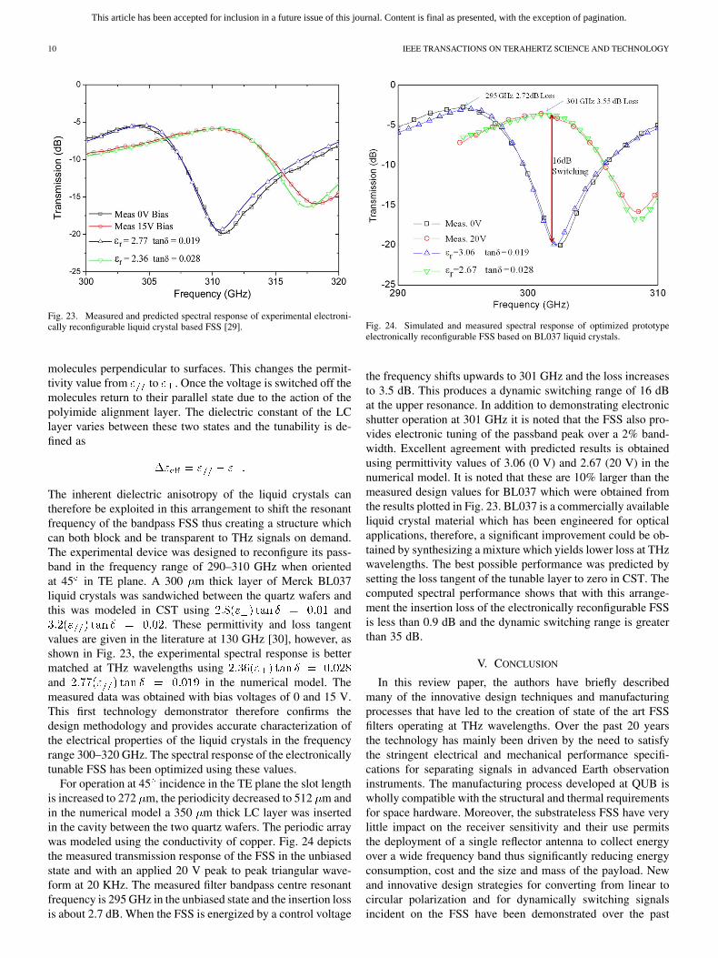
. These permittivity and loss tangentvalues are given in the literature at 130 GHz [30], however, asshown in Fig. 23, the experimental spectral response is bettermatched at THz wavelengths usingand in the numerical model. Themeasured data was obtained with bias voltages of 0 and 15 V.This first technology demonstrator therefore confirms thedesign methodology and provides accurate characterization ofthe electrical properties of the liquid crystals in the frequencyrange 300–320 GHz. The spectral response of the electronicallytunable FSS has been optimized using these values.
For operation at 45 incidence in the TE plane the slot lengthis increased to 272 m, the periodicity decreased to 512 m andin the numerical model a 350 m thick LC layer was insertedin the cavity between the two quartz wafers. The periodic arraywas modeled using the conductivity of copper. Fig. 24 depictsthe measured transmission response of the FSS in the unbiasedstate and with an applied 20 V peak to peak triangular wave-form at 20 KHz. The measured filter bandpass centre resonantfrequency is 295 GHz in the unbiased state and the insertion lossis about 2.7 dB. When the FSS is energized by a control voltage
Fig. 24. Simulated and measured spectral response of optimized prototypeelectronically reconfigurable FSS based on BL037 liquid crystals.
the frequency shifts upwards to 301 GHz and the loss increasesto 3.5 dB. This produces a dynamic switching range of 16 dBat the upper resonance. In addition to demonstrating electronicshutter operation at 301 GHz it is noted that the FSS also pro-vides electronic tuning of the passband peak over a 2% band-width. Excellent agreement with predicted results is obtainedusing permittivity values of 3.06 (0 V) and 2.67 (20 V) in thenumerical model. It is noted that these are 10% larger than themeasured design values for BL037 which were obtained fromthe results plotted in Fig. 23. BL037 is a commercially availableliquid crystal material which has been engineered for opticalapplications, therefore, a significant improvement could be ob-tained by synthesizing a mixture which yields lower loss at THzwavelengths. The best possible performance was predicted bysetting the loss tangent of the tunable layer to zero in CST. Thecomputed spectral performance shows that with this arrange-ment the insertion loss of the electronically reconfigurable FSSis less than 0.9 dB and the dynamic switching range is greaterthan 35 dB.
V. CONCLUSION
In this review paper, the authors have briefly describedmany of the innovative design techniques and manufacturingprocesses that have led to the creation of state of the art FSSfilters operating at THz wavelengths. Over the past 20 yearsthe technology has mainly been driven by the need to satisfythe stringent electrical and mechanical performance specifi-cations for separating signals in advanced Earth observationinstruments. The manufacturing process developed at QUB iswholly compatible with the structural and thermal requirementsfor space hardware. Moreover, the substrateless FSS have verylittle impact on the receiver sensitivity and their use permitsthe deployment of a single reflector antenna to collect energyover a wide frequency band thus significantly reducing energyconsumption, cost and the size and mass of the payload. Newand innovative design strategies for converting from linear tocircular polarization and for dynamically switching signalsincident on the FSS have been demonstrated over the past
This article has been accepted for inclusion in a future issue of this journal. Content is final as presented, with the exception of pagination.
DICKIE et al.: THz FSS FILTERS FOR EARTH OBSERVATION REMOTE SENSING INSTRUMENTS 11
three years. These devices exploit the same computationalanalysis techniques and manufacturing processes that havebeen developed to produce space qualified demultiplexingfilters. The additional functionality afforded by these FSS couldfind applications in imaging devices and other emerging THztechnologies.
ACKNOWLEDGMENT
The studies reported in this paper were carried out at theQueen’s University Belfast. The authors would like to acknowl-edge the contribution to this work which was made by Dr. P. deMaagt (ESA); Dr. N. Grant, Ms. Y. Munro, Prof. M. Johnson,and P. Howard (EADS Astrium); and Dr. P. Huggard, Dr. M.Henry, and B. Moyna (RAL).
REFERENCES
[1] C. Mangenot, “Space antennas: ESA’s perspectives on future needsand technologies,” presented at the 13th Int. Symp. on Antennas, Nice,France, 2004.
[2] V. Kangas, C. Lin, and M. Betto, “Microwave instrument requirementsand technology needs for the post-EPS mission,” in Proc 31st ESTECAntenna Workshop on Millimetre and Sub-Millimetre Waves—FromTechnologies to Systems, May 2009, pp. 501–506.
[3] R. J. Martin and D. H. Martin, “Quasi-optical antennas for radiometricremote sensing,” Electron. Commun. Eng. J., vol. 8, pp. 37–48, Feb.1996.
[4] M. Oldfield, B. Moyna, E. Allouis, R. Brunt, U. Cortesi, B. Ellison,J. Ellison, J. Eskell, T. Forward, T. Jones, D. Lamarre, J. Langen,P. de Maagt, D. Matheson, I. Morgan, J. Reburn, and R. Siddan,“MARSCHALS: Development of an airborne millimetre-wave limbsounder,” in Proc. SPIE 8th Int. Symp. on Remote Sensing, Sept. 2001,vol. 4540, pp. 221–228.
[5] R. Dickie, R. Cahill, H. S. Gamble, V. F. Fusco, A. Schuchinsky, andN. Grant, “Spatial demultiplexing in the sub-mm wave band using mul-tilayer free-standing frequency selective surfaces,” IEEE Trans. An-tennas Propag., vol. 53, no. 6, pp. 1903–1911, Jun. 2005.
[6] R. Dickie, R. Cahill, H. S. Gamble, V. F. Fusco, M. Henry, M. L. Old-field, P. G. Huggard, P. Howard, N. Grant, Y. Munro, and P. de Maagt,“Submillimeter wave frequency selective surface with polarization in-dependent spectral responses,” Proc. IEEE Antennas and Propagation,vol. 57, pp. 1985–1994, Jul. 2009.
[7] R. Cahill, W. J. Hall, and R. J. Martin, “Technologies for millimeterremote sensing antennas,” in IEE/SEE Seminar Dig. on Spacecraft An-tennas, 1994, pp. 8/1–8/8.
[8] R. Cahill and E. A. Parker, “Frequency selective surface design forsubmillimetric demultiplexing,” Microw. Opt. Technol. Lett., vol. 7, pp.595–597, Sep. 1994.
[9] R. Cahill, I. M. Sturland, J. W. Bowen, E. A. Parker, and A. C. de CLima, “Frequency selective surfaces for millimetre and submillimetrewave quasi-optical demultiplexing,” Int., J. Infrared and MillimetreWaves, vol. 14, pp. 1769–1788, Sept. 1993.
[10] R. Cahill and E. A. Parker, “Performance of mm-wave frequency se-lective surfaces in large incident angle quasi-optical systems,” Electron.Lett., vol. 28, pp. 788–789, Apr. 1992.
[11] R. Cahill, E. A. Parker, and I. M. Sturland, “Influence of substrate losstangent on performance of multilayer sub millimetre wave FSS,” Elec-tron. Lett., vol. 31, pp. 1752–1753, Sep. 1995.
[12] R. Cahill, H. S. Gamble, V. F. Fusco, J. C. Vardaxoglou, M. Jayawar-dene, B. Moyna, M. Oldfield, G. Cox, and N. Grant, “Low loss FSSfor channel demultiplexing and image band rejection filtering,” inProc 24th ESTEC AntennaWorkshop on Innovative Periodic Antennas:Photonic Bandgap, Fractal and Freq. Sel. Surfaces, May 2001, pp.103–108.
[13] B. A. Munk, Frequency Selective Surfaces Theory and De-sign. Hoboken, NJ: Wiley, 2000.
[14] R. Cahill, J. C. Vardaxaglou, and M. Jayawardene, “Two layermm-wave FSS of linear slot elements with low insertion loss,” Proc.IEE Microw. Antennas and Propag., vol. 148, pp. 410–412, Dec. 2001.
[15] S. Biber, M. Bozzi, O. Gunther, L. Perregrini, and L. P. Schmidt, “De-sign and testing of frequency-selective surfaces on silicon substratesfor submillimeter-wave applications,” IEEE Trans. Antennas Propag.,vol. 1, no. 9, pp. 2638–2645, Sep. 2006, 54.
[16] R. Dickie, R. Cahill, V. F. Fusco, H. S. Gamble, B. Moyna, P. Huggard,N. Grant, and C. Philpot, “300 GHz high Q resonant slot frequencyselective surface filter,” Proc. IET Microw. Antennas and Propag., vol.151, pp. 31–36, Jan. 2004.
[17] P. H. Siegel and J. A. Lichtenberger, “A technique for fabricating freestanding electrically thick metallic mesh and parallel wire grids for useas millimetre and submillimetre wavelength filters and polarizers,” inIEEE MTT-S Int. Microwave Symp. Dig., May 1990, pp. 1311–1314.
[18] D. W. Porterfield, J. L. Hesler, R. Densing, E. R. Mueller, T. W. Crowe,and R. M. Weikle, “Resonant metal-mesh bandpass filters for the in-frared,” Appl. Opt., vol. 33, pp. 6046–6052, Sept. 1994.
[19] M. E. MacDonald, A. Alexanian, R. A. York, Z. Popovic, and E. N.Grossman, “Spectral transmittance of lossy printed resonant-grid tera-hertz bandpass filters,” Proc. IEEE Trans. Microw. Theory Techn., vol.48, pp. 712–718, April 2000.
[20] Ansoft Corp., “HFSS 3D EM simulation software for RF, wireless,packaging and optoelectronic design,” (Mar. 2011) [Online]. Available:http://www.ansoft.com
[21] AB Millimetre, Paris, France, “AB Millimetre,” (Mar. 2011) [Online].Available: http://www.abmillimetre.com
[22] P. F. Goldsmith, “Quasi-optical techniques offer advantages at mil-limeter frequencies,” Microw. Syst. News, pp. 65–84, Dec. 1983.
[23] R. Dickie, R. Cahill, V. F. Fusco, H. S. Gamble, Y. Munro, and S. Rea,“Recent advances in submillimetre wave FSS technology for passiveremote sensing instruments,” in Proc. 4rd Eur. Conf. on Antennas andPropagation (EuCAP), Barcelona, Spain, Apr. 2010.
[24] CST-Computer Simulation Technology, Darmstadt, Germany, “CST-Comp. Simulation Technology,” 2005 [Online]. Available: http://www.cst.com
[25] R. Dickie, R. Cahill, H. S. Gamble, V. F. Fusco, P. G. Huggard, B.Moyna, M. Oldfield, N. Grant, and P. de Maagt, “Polarisation inde-pendent bandpass FSS,” Electron. Lett., vol. 43, pp. 1013–1015, Sep.2007.
[26] M. Euler, V. F. Fusco, R. Cahill, and R. Dickie, “325 GHz single layersub-millimeter wave FSS based split slot ring linear to circular polar-ization convertor,” IEEE Trans. Antennas Propag., vol. 58, no. 7, pp.2457–2459, Jul. 2010.
[27] B. Y. Toh, R. Cahill, and V. F. Fusco, “Understanding and measuringcircular polarization,” IEEE Trans. Edu., vol. 46, no. 3, pp. 313–319,Aug. 2003.
[28] M. Euler, V. F. Fusco, R. Cahill, and R. Dickie, “Comparison of FSSbased linear to circular polarization converter geometries,” Proc. IETMicrow. Antennas and Propag., vol. 4, pp. 1764–1772, Nov. 2010.
[29] R. Simms, R. Dickie, R. Cahill, N. Mitchell, H. S. Gamble, and V. F.Fusco, “Measurement of electromagnetic properties of liquid crystalsat 300 GHz using a tunable FSS,” presented at the 32nd ESA Workshopon Antennas for Space Applications, Noordwijk, the Netherlands, Oct.2010.
[30] W. Hu, R. Dickie, R. Cahill, H. S. Gamble, M. Y. Ismail, V. F. Fusco,D. Linton, S. P. Rea, and N. Grant, “Liquid crystal tunable mm wavefrequency selective surface,” IEEE Microw. Wireless Compon. Lett.,vol. 17, no. 9, pp. 667–700, Sep. 2007.
Raymond Dickie received the B.Eng. (Hons) andPh.D. degrees in electrical and electronic engineeringfrom The Queen’s University of Belfast, U.K., in2001 and 2004, respectively.
In October 2004 he joined the high frequency elec-tronic circuits and antennas group at The Institute ofElectronics, Communications and Information Tech-nology (ECIT), Belfast, U.K., where he is now em-ployed as a senior engineer working on mm-wavecomponents. His work on freestanding frequency se-lective surfaces has been patented and includes fabri-
cation methods using silicon-on-insulator (SOI), metal and polymer mesh tech-nology. He has experience in photolithographic processing including thick posi-tive and negative photoresist RIE of polymers and oxides, DRIE of silicon, CVDmetal deposition, high conductivity stress controlled electroplating, and SEMimaging methods. He is experienced in working in clean room environmentswhere he develops MEMS devices. He has co authored over 50 publications,his high frequency research interests include numerical modeling of high fre-quency structures and precision quasi-optical measurements in the millimeterand sub-millimeter wave bands.
This article has been accepted for inclusion in a future issue of this journal. Content is final as presented, with the exception of pagination.
12 IEEE TRANSACTIONS ON TERAHERTZ SCIENCE AND TECHNOLOGY
Robert Cahill (M’10–SM’11) received the B.Sc.(1st class, Hons) degree in physics from the Uni-versity of Aston, Birmingham, U.K., in 1979, andthe Ph.D. degree in microwave electronics from theUniversity of Kent, Canterbury, U.K., in 1982.
He joined The Queen’s University of Belfast(QUB), U.K., in 1999 after a 17–year career workingin the UK space and defense industry, where heworked on antenna and passive microwave devicetechnology projects. During this time he pioneeredmethods for predicting the performance of antennas
on complex scattering surfaces such as satellites and has developed techniquesfor analyzing and fabricating mm and sub-mm wave quasi-optical dichroicfilters. Recently, he has established a 100–700 GHz quasi-optical S-parametermeasurement facility at QUB. He has exploited the results of numerousresearch projects, sponsored by the European Space Agency, EADS AstriumSpace Ltd., the British National Space Agency, the Centre for Earth Observa-tion Instrumentation (CEOI), and the UK Meteorological Office, to developquasi-optical demultiplexers for atmospheric sounding radiometers in the range89–500 GHz. These include AMSU-B, AMAS, MARSCHALS and the ESA500 GHz demonstrator. His recent interests also include the characterization ofliquid crystal materials at microwave and mm wavelengths, and strategies forbroad banding and creating active reflectarray antennas. He has (co)—authoredover 130 publications and holds four international patents.
Vincent Fusco (S’82–M’82–SM’96–F’04) receivedthe Bachelors degree (1st class honors) in electricaland electronic engineering, the Ph_D. degree inmicrowave electronics, and the D.Sc. degree forhis work on advanced front end architectures withenhanced functionality, from The Queens Universityof Belfast (QUB), Belfast, Northern Ireland, in 1979,1982, and 2000, respectively.
He is the Technical Director of the High FrequencyLaboratories at The Queens University of Belfast,U.K., and is also Director of the International Centre
for Research for System on Chip and Advanced MicroWireless Integration,SoCaM. His research interests include nonlinear microwave circuit design, andactive and passive antenna techniques. He has published over 420 scientificpapers in major journals and international conferences, and is the author of twotext books. He holds several patents on active and retrodirective antennas andhas contributed invited chapters to books in the fields of active antenna designand EM field computation.
Dr. Fusco is a Fellow of the Royal Academy of Engineering, and a Fellowof the Institution of Electrical Engineers (U.K.). In 1986, he was awarded aBritish Telecommunications Fellowship, and in 1997 he was awarded the NIEngineering Federation Trophy for outstanding industrially relevant research.
Harold S. Gamble graduated from The Queen‘sUniversity of Belfast with a 1st class honours degreein electrical and electronic engineering in 1966, andreceived the Ph.D. degree in 1969.
As a research engineer at The Standard Telecom-munication Laboratories, Harlow, U.K., he estab-lished a polysilicon gate process for MOS integratedcircuits. He was appointed to a lectureship at TheQueen’s University of Belfast, U.K., in 1973, andhas lead research there in silicon device designand related technology including, CCDs, silicided
shallow junctions, rapid thermal CVD, GTOs and Static Induction Thyristors.In 1992 he was promoted to Professor of Microelectronic Engineering, anduntil 2010 was the Director of the Northern Ireland Semiconductor ResearchCentre. Major activity at present is the use of direct silicon wafer bondingfor producing silicon-on-insulator (SOI) substrates for low power bipolartransistor circuits. This includes trench and refill before bond technology andburied metallic layers to eliminate epitaxial layers and to minimize collectorresistance. Ground plane SOI structures incorporating tungsten silicide layersare being investigated for cross talk suppression in mixed signal circuits and forultra short MOSTs. The silicon wafer bonding combined with the integratedcircuit patterning techniques is also being applied to micro-machining appli-cations such as sensors, mechanical actuators and 3-D mm wave components.His other projects include multilayer free-standing frequency selective surfacesfor spatial demultiplexing in the sub-mm wave band, thin film transistors inpolysilicon or bonded silicon on glass for displays/imagers, and high densityinterconnects produced by sputtering and CVD for IC‘s and MR heads. He hasco-authored over 250 publications in the area of silicon devices and thin filmtechnology.
Neil Mitchell (M’96–SM’02) received the B.Sc. andPh.D. degrees in electrical and electronic engineeringfrom The Queen’s University of Belfast, U.K., in1982 and 1986, respectively.
In 1986 he was appointed as a temporary lecturerin Queen’s University Belfast, U.K., where he is cur-rently a senior lecturer in the School of Electronics,Electrical Engineering and Computer Science. Hismain research interests are in semiconductor andmicroelectromechanical systems technology. Hisresearch has encompassed a wide range of device
structures and has included development of technology for fabrication ofsemiconductor devices on substrates including glass and sapphire. His recentresearch has been on technology for fabrication of germanium and germaniumon sapphire devices. In the micromachining area, he has developed technologyfor fabrication of RF MEMS components and sensors for biomedical andenvironmental applications. Recent micromachining activity has been onchemotaxis sensors for biomedical applications, photoacoustic sensors forgreenhouse gas measurement and frequency selective surfaces for RF applica-tions. He is joint author of over 130 publications.