Embed Size (px)
Citation preview
Progress In Electromagnetics Research C, Vol. 77, 167–173, 2017
Wide-Angle Frequency Selective Surface with Ultra-Wideband
Response for Aircraft Stealth Designs
Boyu Hua1, Xiaochun Liu2, Xiaoxiang He1, and Yang Yang1, *
Abstract—An ultra-wideband frequency selective surface (FSS) for wide incident angles is proposed.Its −3 dB bandwidth is from 3.49 GHz to 12.13 GHz, and the fractional bandwidth exceeds 110%. Someparasitic patches are appended to reduce the deviation of resonant frequency under wide-angle incidence.The proposed FSS exhibits an improved stability when the incident angles are in the range from 0◦ to60◦. The relative simulated and measured results are provided to validate its effectiveness.
1. INTRODUCTION
Frequency selective surface (FSS), which can be regarded as a periodic structure consisting of arrangedmetallic patches on dielectric layer (s) [1], has been widely used in stealth radome [2], filter [3], andpolarizer [4] due to the capability of controlling the transmission and reflection characteristics of incidentwaves [5]. With the progress of multifunctional aeronautical electronic system which usually containsseveral antennas with different operating frequencies [6, 7], the need for the ultra-wideband (UWB)FSSs employed in stealth designs of the aircraft is on the rise [8]. In many cases, the angular range ofthe airborne radome reached 50◦ or even 60◦ (e.g., the nose radome) [9], therefore, it is essential thatUWB FSSs provide steady frequency response in wide incident angles.
Researchers have made great progress on the wide-angle UWB FSS since Munk indicated thatreducing the inter-element spacing of unit cell can improve the angular stability of FSS [1]. Comparedwith single-layer structure, a multi-layer FSS which has a smaller inter-element spacing was proposedin [10] to provide an UWB bandwidth with the incident angle in the range from 0◦ to 30◦. The structurein [11] utilized the curved slot element to reduce the inter-element spacing, hence its wideband responsewas capable of remaining stable as the incident angle increases from 0◦ to 40◦. In Ref. [12] and Ref. [13],the UWB FSSs exploiting compact elements possessed a good transmission property when the incidentangle was from 0◦ to 45◦. The studies mentioned above utilized various methods; however, the operatingperformances of these UWB FSSs were still unsatisfactory when the incident angle is over 45◦.
In this paper, a UWB FSS with reduced sensitivity to the incident angle is presented. Its −3 dBbandwidth attains 8.64 GHz (3.49–12.13 GHz), which covers the C and X bands, and the fractionalbandwidth exceeds 110%. Compared with the UWB FSS in [10], the proposed FSS appends someparasitic patches to enhance the capacitive and inductive effects, then provides the more stableperformance at incident angle of 60◦ for both TE and TM polarizations. The unit cell of the proposedFSS is 0.09λ0 × 0.09λ0, where λ0 corresponds to free space wavelength at the lower cut-off frequency,and the overall thickness is 4 mm. Section 2 of the paper brings out the details of the proposed FSSand the simulation results. In Section 3, the measurement setup for fabricated prototype and relateddiscussions are shown.
Received 4 August 2017, Accepted 31 August 2017, Scheduled 5 September 2017* Corresponding author: Yang Yang ([email protected]).1 College of Electronic and Information Engineering, Nanjing University of Aeronautics and Astronautics, Nanjing 211106, China.2 Aeronautical Science Key Lab of High Performance Electromagnetic Windows, The Research Institute for Special Structures ofAeronautical Composite AVIC, Jinan 250023, China.
168 Hua et al.
2. DESIGN AND SIMULATIONS
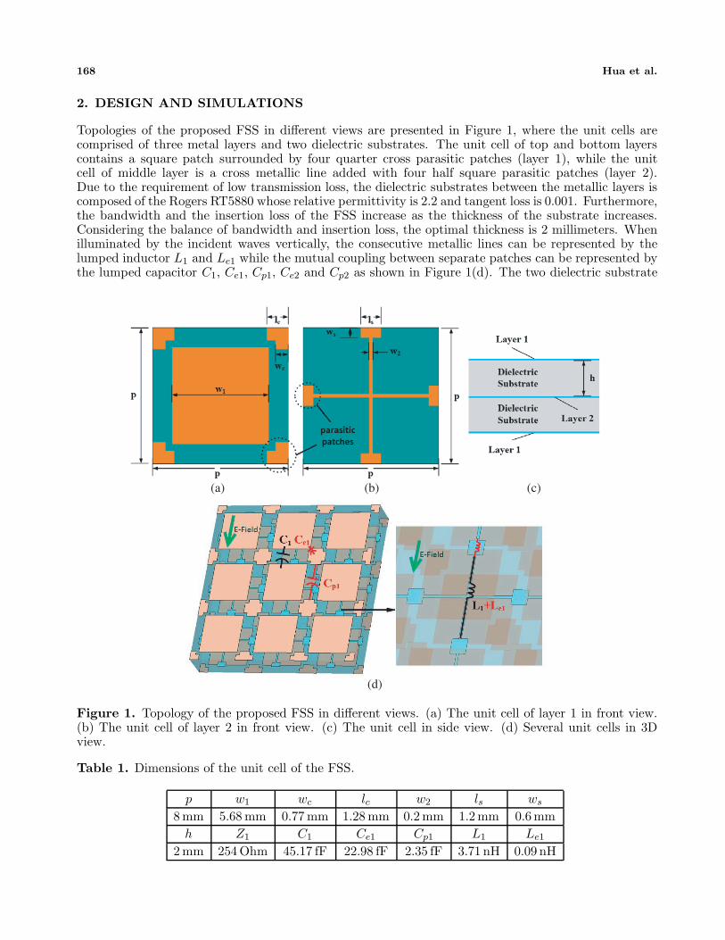
Topologies of the proposed FSS in different views are presented in Figure 1, where the unit cells arecomprised of three metal layers and two dielectric substrates. The unit cell of top and bottom layerscontains a square patch surrounded by four quarter cross parasitic patches (layer 1), while the unitcell of middle layer is a cross metallic line added with four half square parasitic patches (layer 2).Due to the requirement of low transmission loss, the dielectric substrates between the metallic layers iscomposed of the Rogers RT5880 whose relative permittivity is 2.2 and tangent loss is 0.001. Furthermore,the bandwidth and the insertion loss of the FSS increase as the thickness of the substrate increases.Considering the balance of bandwidth and insertion loss, the optimal thickness is 2 millimeters. Whenilluminated by the incident waves vertically, the consecutive metallic lines can be represented by thelumped inductor L1 and Le1 while the mutual coupling between separate patches can be represented bythe lumped capacitor C1, Ce1, Cp1, Ce2 and Cp2 as shown in Figure 1(d). The two dielectric substrate
(a) (b) (c)
(d)
Figure 1. Topology of the proposed FSS in different views. (a) The unit cell of layer 1 in front view.(b) The unit cell of layer 2 in front view. (c) The unit cell in side view. (d) Several unit cells in 3Dview.
Table 1. Dimensions of the unit cell of the FSS.
p w1 wc lc w2 ls ws
8 mm 5.68 mm 0.77 mm 1.28 mm 0.2 mm 1.2 mm 0.6 mmh Z1 C1 Ce1 Cp1 L1 Le1
2 mm 254 Ohm 45.17 fF 22.98 fF 2.35 fF 3.71 nH 0.09 nH
Progress In Electromagnetics Research C, Vol. 77, 2017 169
layers can be modeled as the same short piece of transmission line Z1 whose length equals the thicknessof the substrate. All the parameters are given in Table 1. On the basic of the research in [14], theapproximate formulae of Z1, C1 and L1 are presented as
Z1 =Z0√
(1 − j tan δ)εr
(1)
C1 = −(1 + εr) ε0p
πln
(sin
πp
s1
)(2)
L1 = −μ0p
2π2ln
(sin
πw2
2p
)(3)
s1 =p2 − w2
1 − 8wclc + 4w2c
4p(4)
where Z0 = 377Ω is the free space characteristics impedance, εr the relative dielectric constant of thesubstrate, and parameter s1 represents the average distance between two square patches. Moreover, thecapacitance Cp1 and Ce1 mainly depend on the width of the cross parasitic patch 2wc, the length ofthe cross parasitic patch 2lc and the average distance between the square patch and the parasitic patchse1. Meanwhile, the inductance Le1 is mainly influenced by the space between the effective width of thesquare parasitic patch we1. These parameter can be expressed as
Cp1 = −0.013(1 + εr) ε0p
πln
(sin
πp
sp1
)(5)
Ce1 = −0.324(1 + εr) ε0p
πln
(sin
πp
se1
)(6)
Le1 = −0.012μ0p
π2ln
(sin
πlsws
p2
)(7)
sp1 =2wc (p − 2lc) + (p − w1 − 2wc) (p − 2wc)
p − w1(8)
se1 =
∫ √2lc/2
0
[−x +
√2 (p − w1)
2
]dx +
∫ √2lc
√2lc/2
(x − p − w1 − 2wc
2
)dx
√2lc
. (9)
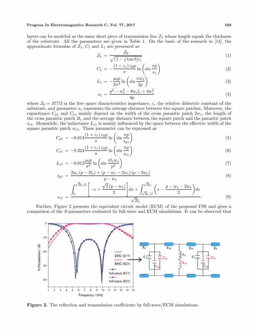
Further, Figure 2 presents the equivalent circuit model (ECM) of the proposed FSS and gives acomparison of the S-parameters evaluated by full-wave and ECM simulations. It can be observed that
Figure 2. The reflection and transmission coefficients by full-wave/ECM simulations.
170 Hua et al.
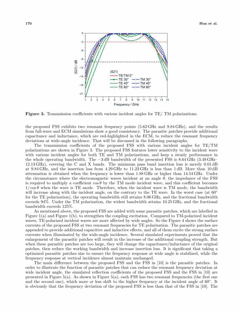
Figure 3. Transmission coefficients with various incident angles for TE/ TM polarizations.
the proposed FSS exhibits two resonant frequency points (5.62 GHz and 9.84 GHz), and the resultsfrom full-wave and ECM simulations show a good consistency. The parasitic patches provide additionalcapacitance and inductance, which are red-highlighted in the ECM, to reduce the resonant frequencydeviations at wide-angle incidence. That will be discussed in the following paragraphs.
The transmission coefficients of the proposed FSS with various incident angles for TE/TMpolarizations are shown in Figure 3. The proposed FSS features lower sensitivity to the incident wavewith various incident angles for both TE and TM polarizations, and keep a steady performance inthe whole operating bandwidth. The −3 dB bandwidth of the presented FSS is 8.64 GHz (3.49 GHz–12.13 GHz), covering the C and X bands. The minimum pass band insertion loss is merely 0.01 dBat 9.84 GHz, and the insertion loss from 4.29 GHz to 11.23 GHz is less than 1 dB. More than 10 dBattenuation is obtained when the frequency is lower than 1.88 GHz or higher than 14.54 GHz. Underthe circumstance where the electromagnetic waves incident at an angle θ, the impedance of the FSSis required to multiply a coefficient cos θ by the TM mode incident wave, and this coefficient becomes1/ cos θ when the wave is TE mode. Therefore, when the incident wave is TM mode, the bandwidthwill increase along with the incident angle, on the contrary to the TE wave. In the worst case (at 60◦for the TE polarization), the operating bandwidth still attains 8.06 GHz, and the fractional bandwidthexceeds 94%. Under the TM polarization, the widest bandwidth attains 10.25 GHz, and the fractionalbandwidth exceeds 125%.
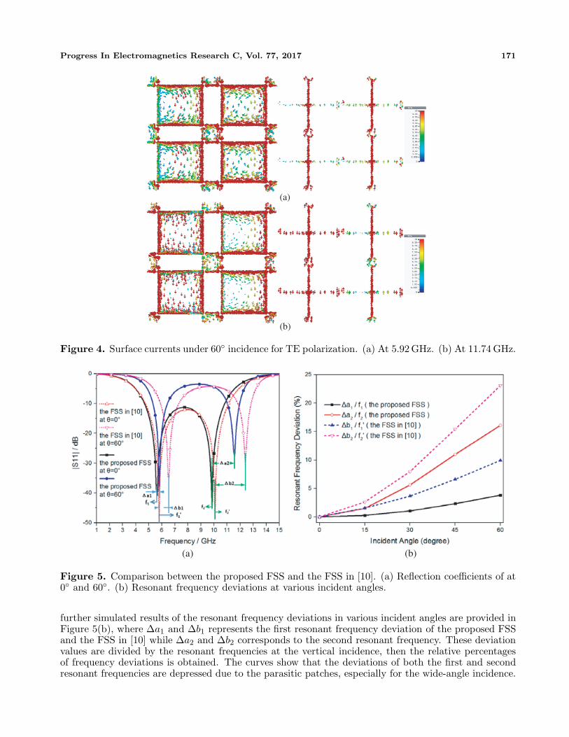
As mentioned above, the proposed FSS are added with some parasitic patches, which are labelled inFigure 1(a) and Figure 1(b), to strengthen the coupling excitation. Compared to TM-polarized incidentwaves, TE-polarized incident waves are more affected by wide angles. So the Figure 4 shows the surfacecurrents of the proposed FSS at two resonant frequencies for TE polarization. The parasitic patches areappended to provide additional capacitive and inductive effects, and all of them excite the strong surfacecurrents when illuminated by the wide-angle incidence. Several simulated experiments proved that theenlargement of the parasitic patches will result in the increase of the additional coupling strength. Butwhen these parasitic patches are too large, they will change the capacitance/inductance of the originalpatches, then reduce the working bandwidth and increase insertion loss. It is significant that taking aoptimized parasitic patches size to ensure the frequency response at wide angle is stabilized, while thefrequency response at vertical incidence almost maintain unchanged.
The main difference between the proposed FSS and the FSS in [10] is the parasitic patches. Inorder to illustrate the function of parasitic patches that can reduce the resonant frequency deviation atwide incident angle, the simulated reflection coefficients of the proposed FSS and the FSS in [10] arepresented in Figure 5(a). As shown in Figure 5(a), each FSS has two resonant frequencies (the first oneand the second one), which more or less shift to the higher frequency at the incident angle of 60◦. Itis obviously that the frequency deviation of the proposed FSS is less than that of the FSS in [10]. The
Progress In Electromagnetics Research C, Vol. 77, 2017 171
(a)
(b)
Figure 4. Surface currents under 60◦ incidence for TE polarization. (a) At 5.92 GHz. (b) At 11.74 GHz.
(a) (b)
Figure 5. Comparison between the proposed FSS and the FSS in [10]. (a) Reflection coefficients of at0◦ and 60◦. (b) Resonant frequency deviations at various incident angles.
further simulated results of the resonant frequency deviations in various incident angles are provided inFigure 5(b), where Δa1 and Δb1 represents the first resonant frequency deviation of the proposed FSSand the FSS in [10] while Δa2 and Δb2 corresponds to the second resonant frequency. These deviationvalues are divided by the resonant frequencies at the vertical incidence, then the relative percentagesof frequency deviations is obtained. The curves show that the deviations of both the first and secondresonant frequencies are depressed due to the parasitic patches, especially for the wide-angle incidence.
172 Hua et al.
3. EXPERIMENT AND RESULTS
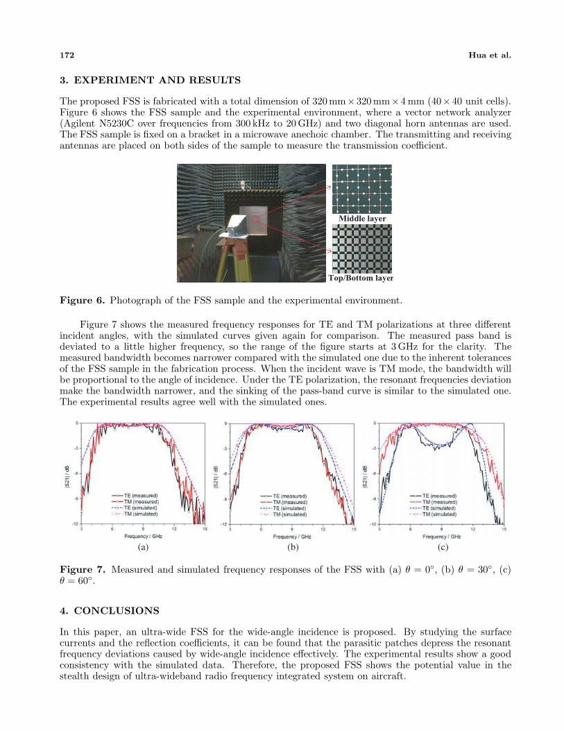
The proposed FSS is fabricated with a total dimension of 320mm×320mm×4 mm (40×40 unit cells).Figure 6 shows the FSS sample and the experimental environment, where a vector network analyzer(Agilent N5230C over frequencies from 300 kHz to 20 GHz) and two diagonal horn antennas are used.The FSS sample is fixed on a bracket in a microwave anechoic chamber. The transmitting and receivingantennas are placed on both sides of the sample to measure the transmission coefficient.
Middle layer
Top/Bottom layer
Figure 6. Photograph of the FSS sample and the experimental environment.
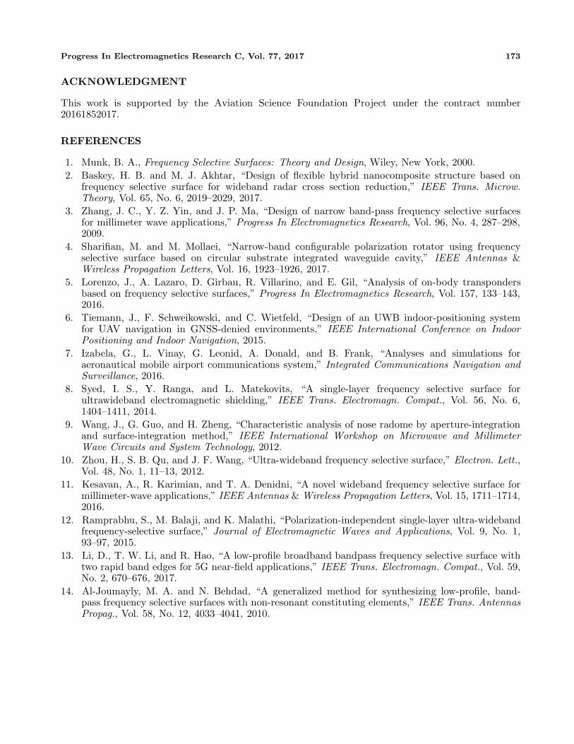
Figure 7 shows the measured frequency responses for TE and TM polarizations at three differentincident angles, with the simulated curves given again for comparison. The measured pass band isdeviated to a little higher frequency, so the range of the figure starts at 3 GHz for the clarity. Themeasured bandwidth becomes narrower compared with the simulated one due to the inherent tolerancesof the FSS sample in the fabrication process. When the incident wave is TM mode, the bandwidth willbe proportional to the angle of incidence. Under the TE polarization, the resonant frequencies deviationmake the bandwidth narrower, and the sinking of the pass-band curve is similar to the simulated one.The experimental results agree well with the simulated ones.
(a) (b) (c)
Figure 7. Measured and simulated frequency responses of the FSS with (a) θ = 0◦, (b) θ = 30◦, (c)θ = 60◦.
4. CONCLUSIONS
In this paper, an ultra-wide FSS for the wide-angle incidence is proposed. By studying the surfacecurrents and the reflection coefficients, it can be found that the parasitic patches depress the resonantfrequency deviations caused by wide-angle incidence effectively. The experimental results show a goodconsistency with the simulated data. Therefore, the proposed FSS shows the potential value in thestealth design of ultra-wideband radio frequency integrated system on aircraft.
Progress In Electromagnetics Research C, Vol. 77, 2017 173
ACKNOWLEDGMENT
This work is supported by the Aviation Science Foundation Project under the contract number20161852017.
REFERENCES
1. Munk, B. A., Frequency Selective Surfaces: Theory and Design, Wiley, New York, 2000.2. Baskey, H. B. and M. J. Akhtar, “Design of flexible hybrid nanocomposite structure based on
frequency selective surface for wideband radar cross section reduction,” IEEE Trans. Microw.Theory, Vol. 65, No. 6, 2019–2029, 2017.
3. Zhang, J. C., Y. Z. Yin, and J. P. Ma, “Design of narrow band-pass frequency selective surfacesfor millimeter wave applications,” Progress In Electromagnetics Research, Vol. 96, No. 4, 287–298,2009.
4. Sharifian, M. and M. Mollaei, “Narrow-band configurable polarization rotator using frequencyselective surface based on circular substrate integrated waveguide cavity,” IEEE Antennas &Wireless Propagation Letters, Vol. 16, 1923–1926, 2017.
5. Lorenzo, J., A. Lazaro, D. Girbau, R. Villarino, and E. Gil, “Analysis of on-body transpondersbased on frequency selective surfaces,” Progress In Electromagnetics Research, Vol. 157, 133–143,2016.
6. Tiemann, J., F. Schweikowski, and C. Wietfeld, “Design of an UWB indoor-positioning systemfor UAV navigation in GNSS-denied environments,” IEEE International Conference on IndoorPositioning and Indoor Navigation, 2015.
7. Izabela, G., L. Vinay, G. Leonid, A. Donald, and B. Frank, “Analyses and simulations foraeronautical mobile airport communications system,” Integrated Communications Navigation andSurveillance, 2016.
8. Syed, I. S., Y. Ranga, and L. Matekovits, “A single-layer frequency selective surface forultrawideband electromagnetic shielding,” IEEE Trans. Electromagn. Compat., Vol. 56, No. 6,1404–1411, 2014.
9. Wang, J., G. Guo, and H. Zheng, “Characteristic analysis of nose radome by aperture-integrationand surface-integration method,” IEEE International Workshop on Microwave and MillimeterWave Circuits and System Technology, 2012.
10. Zhou, H., S. B. Qu, and J. F. Wang, “Ultra-wideband frequency selective surface,” Electron. Lett.,Vol. 48, No. 1, 11–13, 2012.
11. Kesavan, A., R. Karimian, and T. A. Denidni, “A novel wideband frequency selective surface formillimeter-wave applications,” IEEE Antennas & Wireless Propagation Letters, Vol. 15, 1711–1714,2016.
12. Ramprabhu, S., M. Balaji, and K. Malathi, “Polarization-independent single-layer ultra-widebandfrequency-selective surface,” Journal of Electromagnetic Waves and Applications, Vol. 9, No. 1,93–97, 2015.
13. Li, D., T. W. Li, and R. Hao, “A low-profile broadband bandpass frequency selective surface withtwo rapid band edges for 5G near-field applications,” IEEE Trans. Electromagn. Compat., Vol. 59,No. 2, 670–676, 2017.
14. Al-Joumayly, M. A. and N. Behdad, “A generalized method for synthesizing low-profile, band-pass frequency selective surfaces with non-resonant constituting elements,” IEEE Trans. AntennasPropag., Vol. 58, No. 12, 4033–4041, 2010.