Embed Size (px)
Citation preview
106
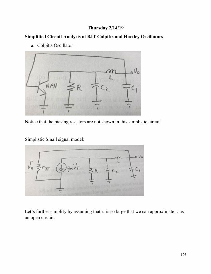
Thursday 2/14/19
Simplified Circuit Analysis of BJT Colpitts and Hartley Oscillators
a. Colpitts Oscillator
Notice that the biasing resistors are not shown in this simplistic circuit.
Simplistic Small signal model:
Let’s further simplify by assuming that rπ is so large that we can approximate rπ as an open circuit:
107
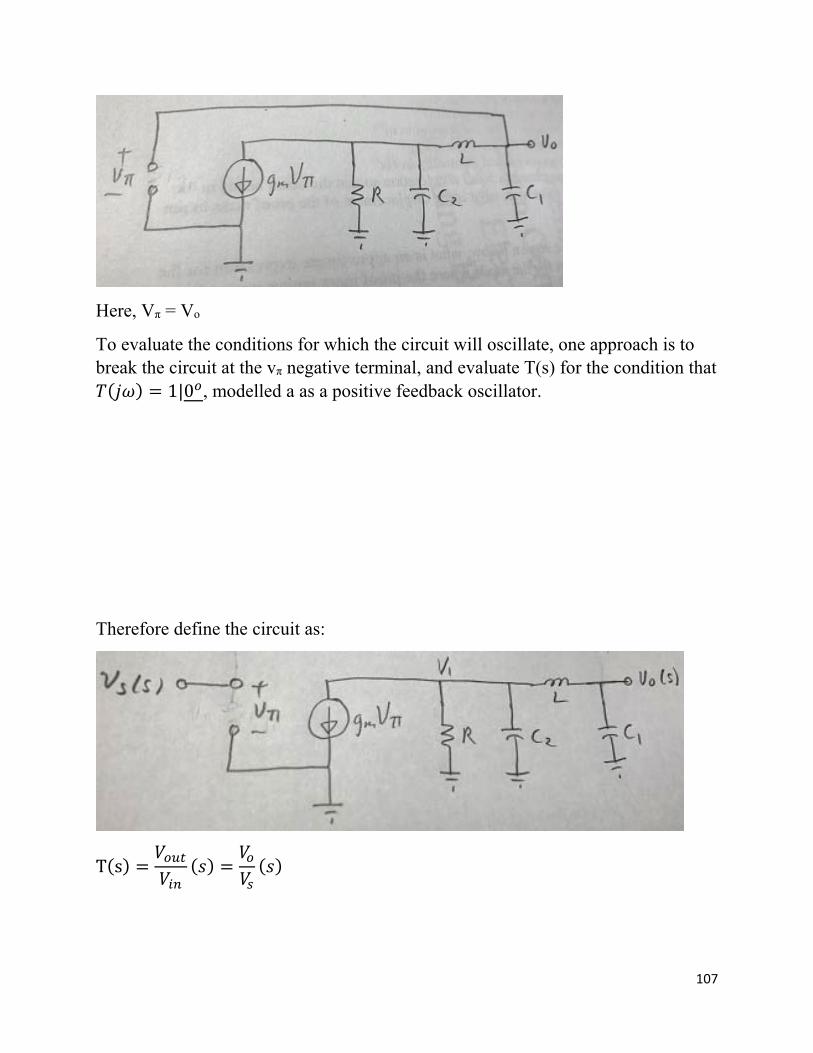
Here, Vπ = Vo
To evaluate the conditions for which the circuit will oscillate, one approach is to break the circuit at the vπ negative terminal, and evaluate T(s) for the condition that
1|0 , modelled a as a positive feedback oscillator.
Therefore define the circuit as:
T s
108
1 10
1 (1)
1 1 1
1 (2)
(1)→(2)
1 1
Then calculate T(s) and T(jω)
For oscillation: find the constraints so that 1|0 .
Obviously, there are s4 terms, making this a 4th order system.
Much arithmetic will be required to obtain 1|0 .
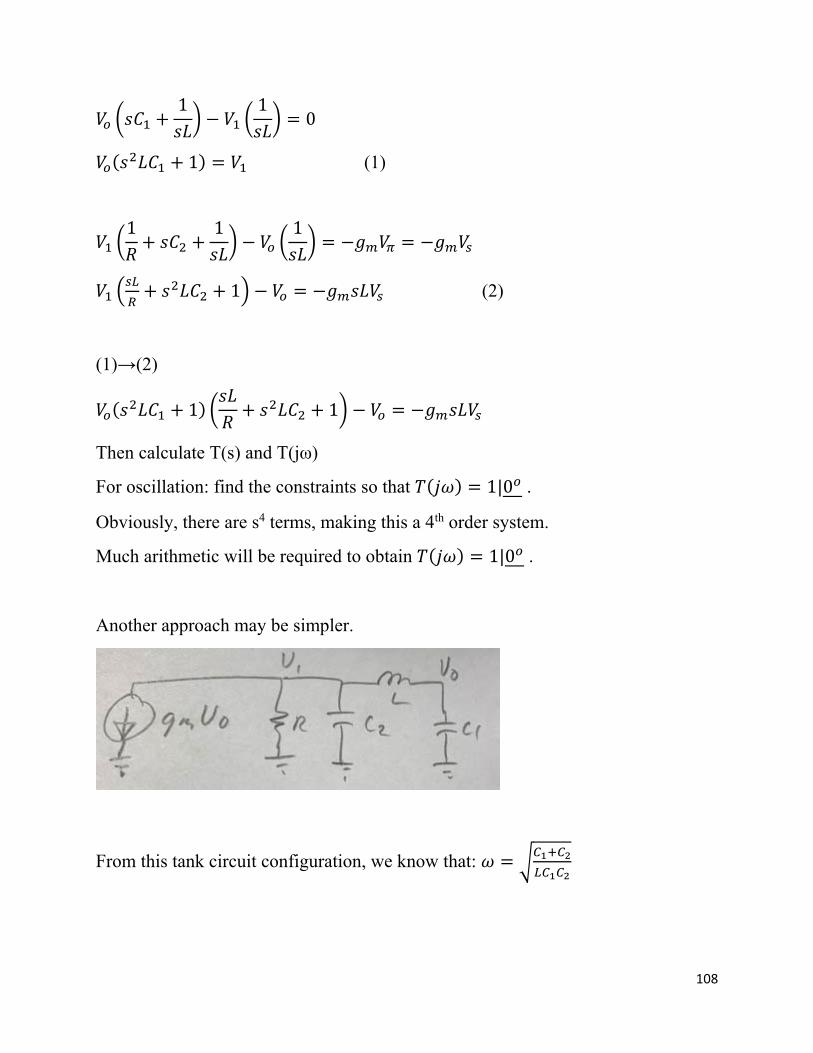
Another approach may be simpler.
From this tank circuit configuration, we know that:
109
For oscillation, the energy supplied by gmVo must be equal to or greater than the energy dissipated by R:
| |
1 10
1
|
|1
|1
|1
|
|
|
Therefore:
110
1
This is the condition for oscillation.
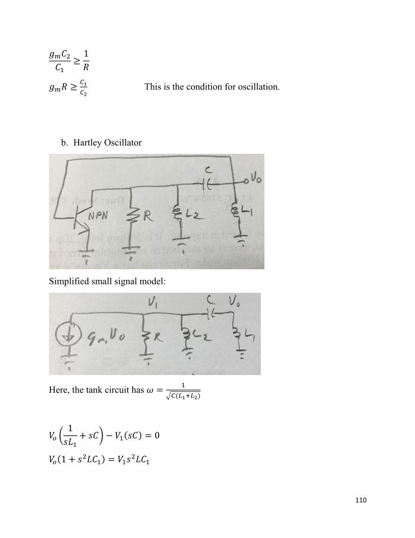
b. Hartley Oscillator
Simplified small signal model:
Here, the tank circuit has
10
1
111
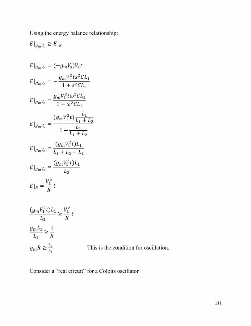
Using the energy balance relationship:
| |
|
|1
|1
|1
|
|
|
1
This is the condition for oscillation.
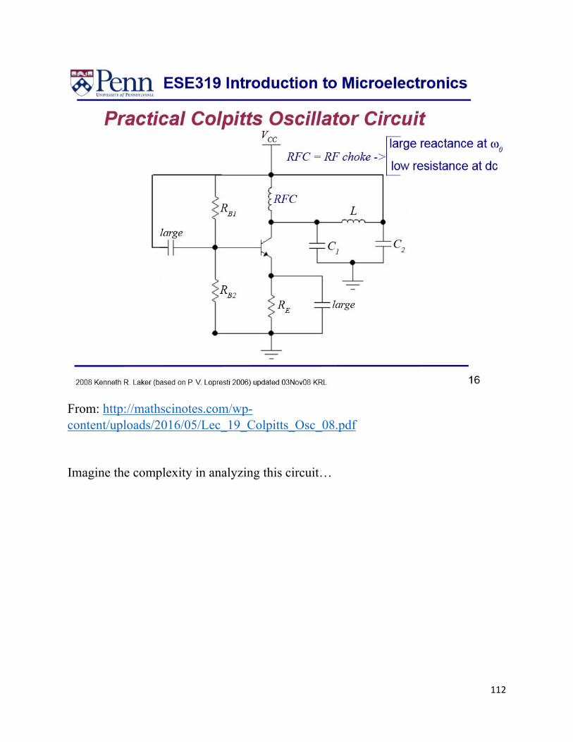
Consider a “real circuit” for a Colpits oscillator
112
From: http://mathscinotes.com/wp-content/uploads/2016/05/Lec_19_Colpitts_Osc_08.pdf
Imagine the complexity in analyzing this circuit…
113
Other Transistor Oscillators
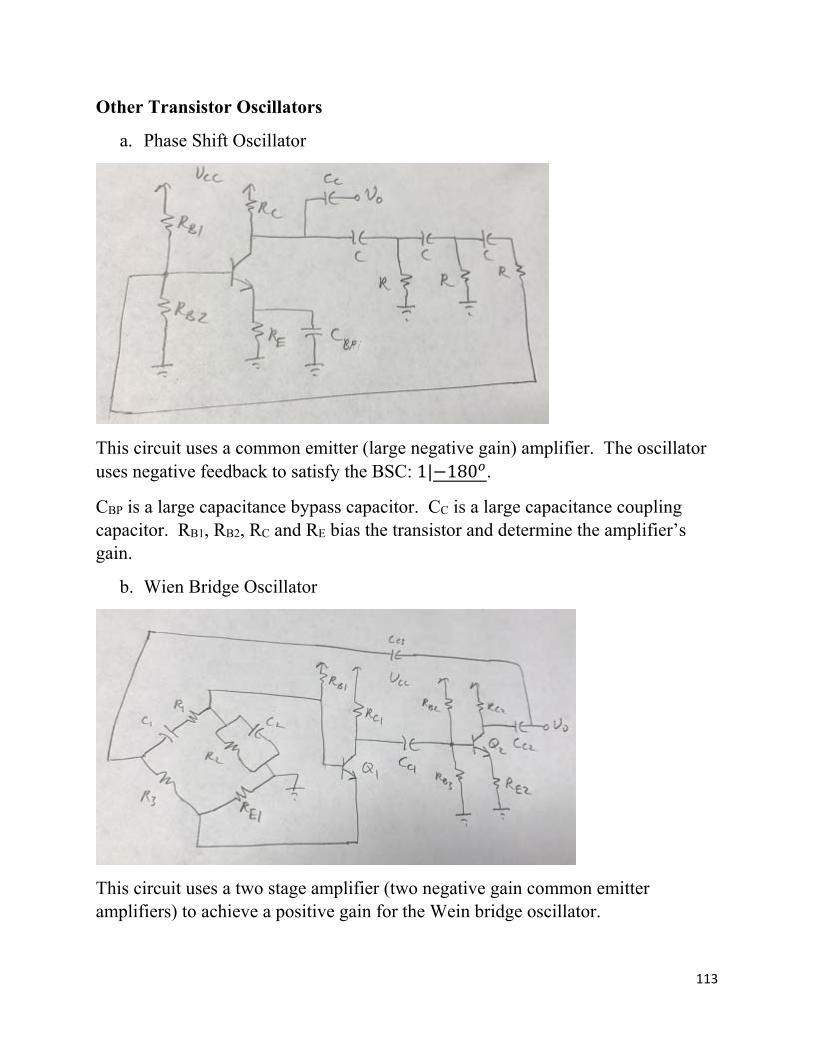
a. Phase Shift Oscillator
This circuit uses a common emitter (large negative gain) amplifier. The oscillator uses negative feedback to satisfy the BSC: 1| 180 .
CBP is a large capacitance bypass capacitor. CC is a large capacitance coupling capacitor. RB1, RB2, RC and RE bias the transistor and determine the amplifier’s gain.
b. Wien Bridge Oscillator
This circuit uses a two stage amplifier (two negative gain common emitter amplifiers) to achieve a positive gain for the Wein bridge oscillator.
114
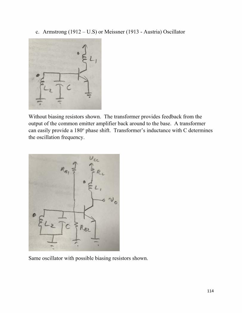
c. Armstrong (1912 – U.S) or Meissner (1913 - Austria) Oscillator
Without biasing resistors shown. The transformer provides feedback from the output of the common emitter amplifier back around to the base. A transformer can easily provide a 180o phase shift. Transformer’s inductance with C determines the oscillation frequency.
Same oscillator with possible biasing resistors shown.
115
d. Oscillators Using Crystal and Ceramic Resonators
Some limiting factors in LC oscillators include:
(1) The size and weight of inductors (particularly at low frequencies) (2) Resistive losses in inductors (low inductor Q) (3) Inductive accuracy of inductors (4) Long term stability
Piezoelectric crystal and ceramic resonators are therefore used to improve these issues.
Quartz is a piezoelectric material. Piezoelectric materials experience a small dimensional change is response to an applied voltage. Also, they generate an electric charge in response to an applied mechanical stress. Some ceramics also exhibit piezoelectric properties.
Schematic symbol for piezoelectric crystal and ceramic resonators:
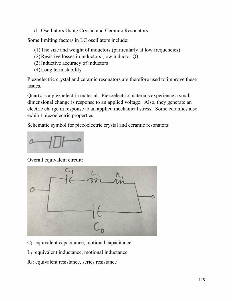
Overall equivalent circuit:
C1: equivalent capacitance, motional capacitance
L1: equivalent inductance, motional inductance
R1: equivalent resistance, series resistance
116
Co: inner electrode capacitance, holder or shunt capacitance
The resonator has an impedance Z=R+jX
fr is the resonant frequency:
fa is the anti-resonant frequency: 1
Qm is the mechanical quality factor:
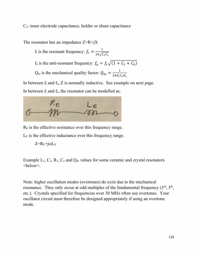
In between fr and fa, Z is normally inductive. See example on next page.
In between fr and fa, the resonator can be modelled as:
RE is the effective resistance over this frequency range.
LE is the effective inductance over this frequency range.
Z=RE+jωLE
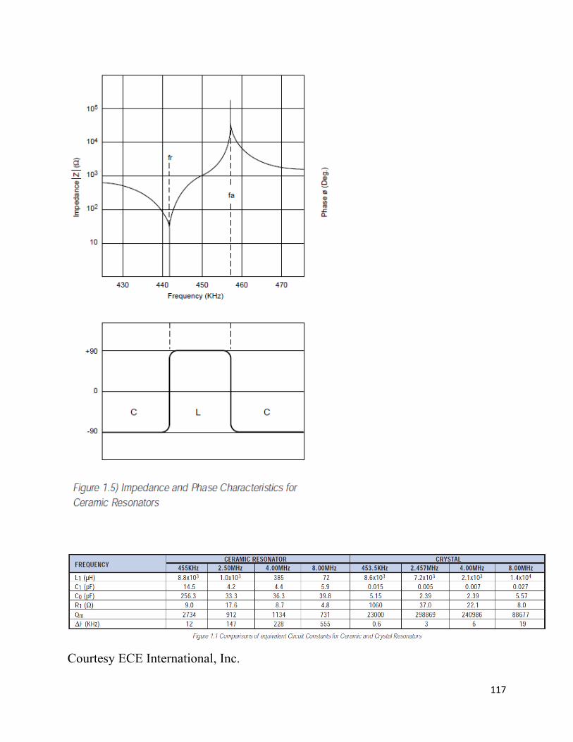
Example L1, C1, R1, Co and Qm values for some ceramic and crystal resonators <below>.
Note: higher oscillation modes (overtones) do exist due to the mechanical resonance. They only occur at odd multiples of the fundamental frequency (3rd, 5th, etc.). Crystals specified for frequencies over 30 MHz often use overtones. Your oscillator circuit must therefore be designed appropriately if using an overtone mode.
117
Courtesy ECE International, Inc.
118
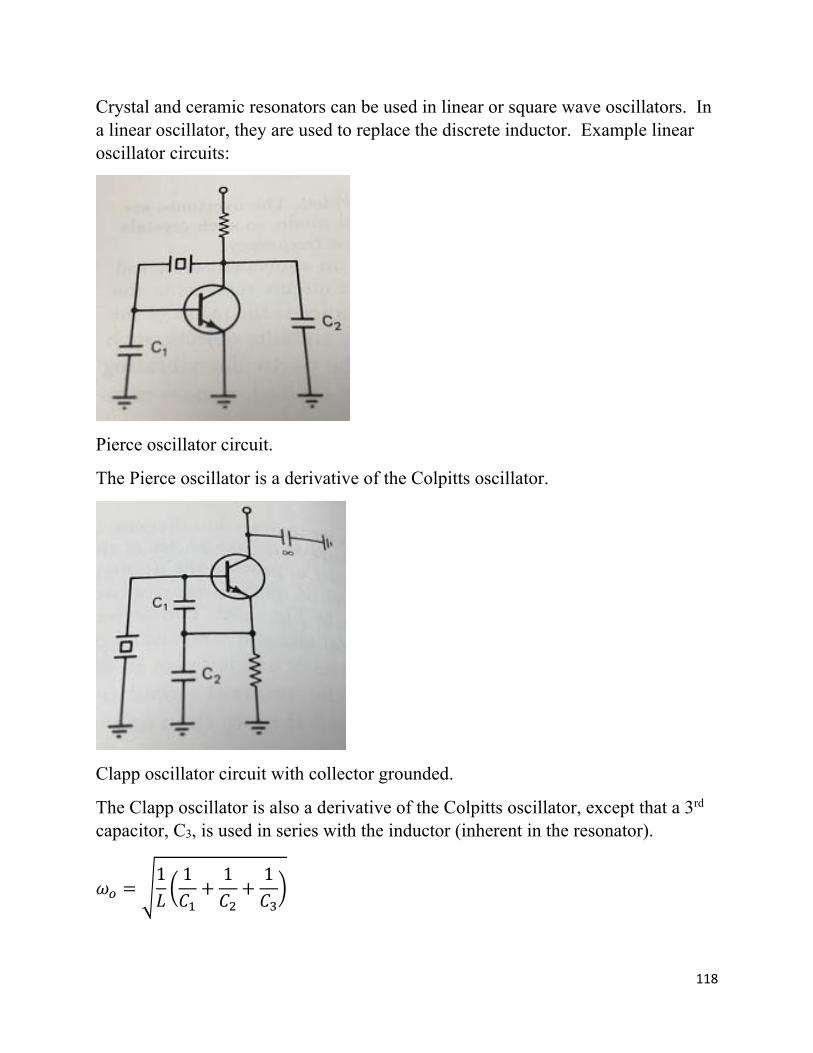
Crystal and ceramic resonators can be used in linear or square wave oscillators. In a linear oscillator, they are used to replace the discrete inductor. Example linear oscillator circuits:
Pierce oscillator circuit.
The Pierce oscillator is a derivative of the Colpitts oscillator.
Clapp oscillator circuit with collector grounded.
The Clapp oscillator is also a derivative of the Colpitts oscillator, except that a 3rd capacitor, C3, is used in series with the inductor (inherent in the resonator).
1 1 1 1
119
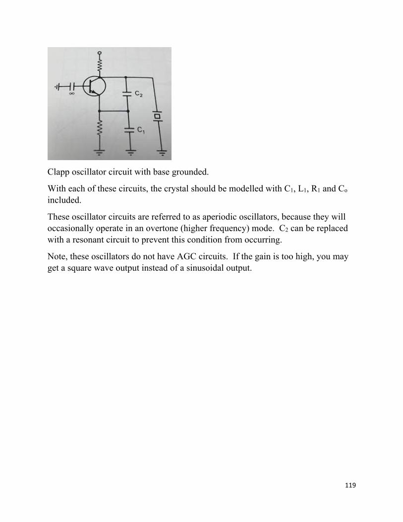
Clapp oscillator circuit with base grounded.
With each of these circuits, the crystal should be modelled with C1, L1, R1 and Co included.
These oscillator circuits are referred to as aperiodic oscillators, because they will occasionally operate in an overtone (higher frequency) mode. C2 can be replaced with a resonant circuit to prevent this condition from occurring.
Note, these oscillators do not have AGC circuits. If the gain is too high, you may get a square wave output instead of a sinusoidal output.
120
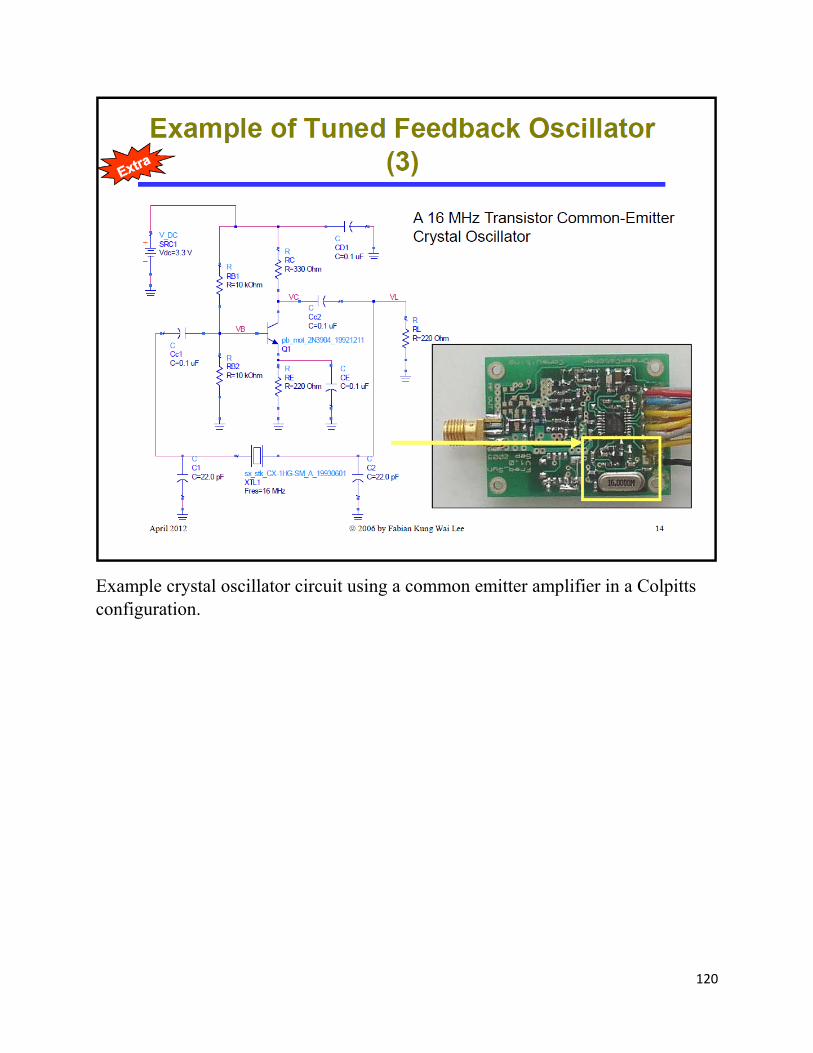
Example crystal oscillator circuit using a common emitter amplifier in a Colpitts configuration.