Embed Size (px)
Citation preview
Engineering Department GENERAL RADIO COMPAIW Cambridge, Mass.
Reprint No, A-70 Reprinted kom W E Transactions on Instrumentation, October, 1955
LOCKED OSCILLATORS IN FREQUENCL' STANDARDS AND ~~~ MIMS-S
James K. Clam General Radio C o m p q
Cambridge, Massachusetts
A locked oscPlZator may be defined as an oscillator autmnatically maintained in fixed phase wrtth respect to a reference frequency. The aver- age frequency of the locked oscillator, xeferred t o the reference eeqnency, is iderrtical d t h that o f the reference source.
Lockad oscillators can be appued to qmtmms f o r multiplication, d3.dslon, addition and s u b t r a c t i o n of A.eqneneies. The fmdmenhl fmqueney of a lacked oscillator may be equal to t h e refer- ence frequency, m y b a r a harmonic ~elatLonshLp to it, or m ~ ~ g differ from it by a f i xed or variable amount. An o s d l l a t o r locked to am b~x7pord.c of a series acts as a f i l t e ~ of high discrimlna"tion, reducing unwanted frequency components fn t h e out- plrt * The output level of the locked osc-illator can be mmarlg times higher than that of t h e reference somce.
Methods and Applications
The applicability of locked oscillators to m a n y problems of fiequen~p standardization and measmement is e ~ d e n t . It wLJrL11 k apprapdate
IW to r e d e w briefly some of the w q r s in wHch an bscillator can ba locked and to consider some rep- re sentatlve appliaations .
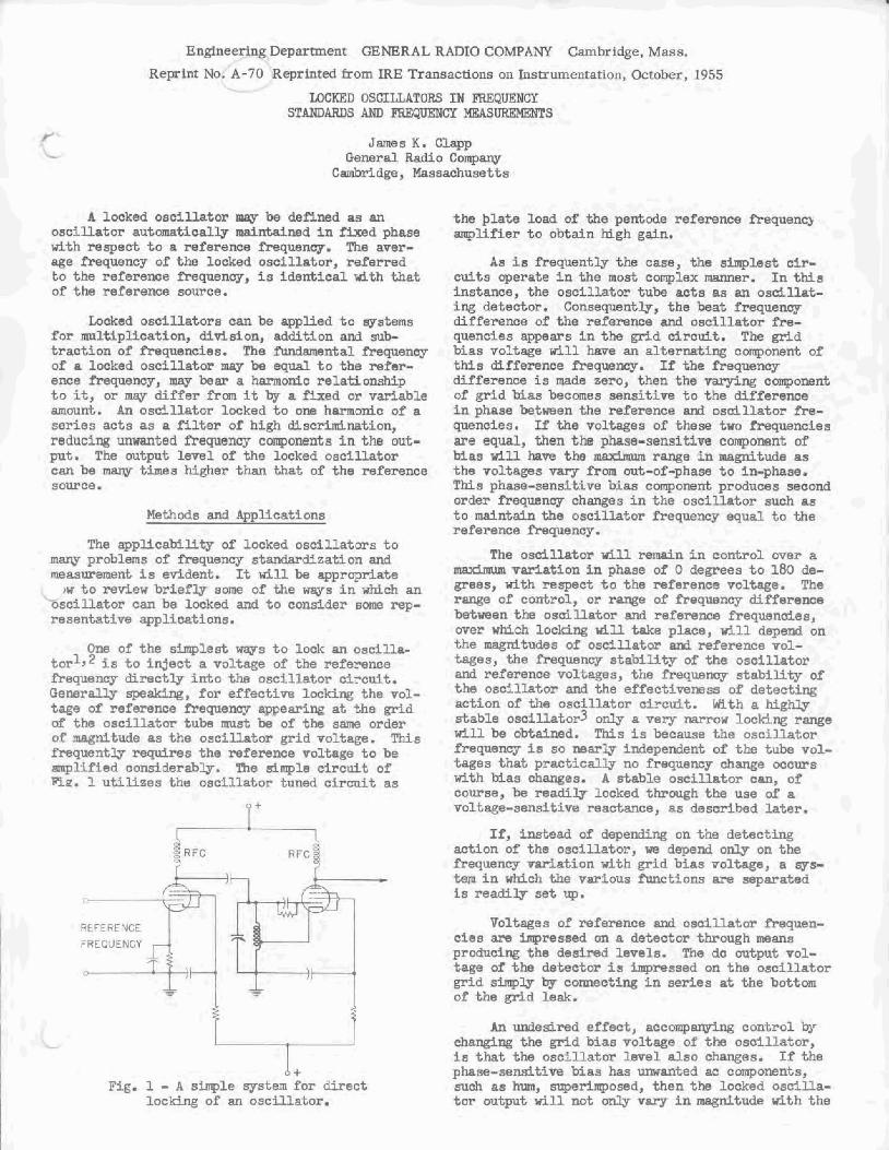
One of t h e slmplsst ways t o lock an oscflla- tor1? 5s to inject a voltwe of the reference frequency directly i n t o the oscillator ctrcuit. Generaw speaking, f o r effective locking the vol- tage of ref eronce fiequancy appearing at ",he grid of t he oscillator tube must be of t h e same order of mgnikude as t h e oscillator grid voltage. TMs fmquent3y r-res the reference volfaga to be q l i f i e d considerabb. Tne Bimple eircuit of Fig. 1 uti l izes the oscfllator tuned c b c u i t as
the plate load o f the pentcde referenee Srequenq amplifier to obtain high gain.
As is Frequently the case, the sirrrplest cir- d t a operate in the most ~ o m p l s x mamar. In this instanca, the ooscillator tube acts as an o s d l l a t - ing detector. Consequently, the beat frequency difference of the reference amt oscZLlator f i e - quencies a p a r s in the circuit. The grid bLas voltage dl1 have an alternaking component of tMa difference frequency, If the fiequenay difference is made zero, then the varying comp~nent o f p f d bias becmes sensitive to the difference In phase betmen the reference a d osci l la tor fre- quenctes. If the voltages of these two Prequencies are equal, then the phase-sensitin coqonsnt of bias wlll have tho m- range in magnitude as the voltages varg from out-of-phase to in-phase. This phase -aensittve bias component produces seeend order frequency changes in t h e oscf llator such as to mairrtafn the o s c i l l a t o r frequency equal to the reference frequency.
The o s d l l a t o r ui31 remain i n con t ro l over a mxhm var3.atj.m i n phase of O degrees t o 180 de- greas, dth respect to the ~eferencs voltage. The range of e a n t ~ o l , or range o f frequency difference between the osoi llator and reference f requerncies, over which locking tCU t a ke place, wL11 depend on t h e magrdkudes of o s d l l a t o r d reference vol- tages, the frequency stability of the osoillator and reference voltages, the frequency stability of the oscillator and t h e effectLmmss of detecting action of the osefllator c5rcult. fith a MgMy stable oseiXLator3 00 a very m u lockilrg r w e will be obtained. This is because the oscillator freqnene~r i s so marly independent of the tube 701- tagss that practfcally no frequency change occurs Kith bias charges. A stable osc i l l a to r caa, of course, be readily locked through the use of a voltage-ssnaitLve reactance, as described Jater.
I * FTg. 1 - R simple system f o r direct
locking o f an oscl l lakor.
If, indead af depending on t h s d e t e c t k g action of the oscillator, we depend only on t h e frequency m a t i o n d t h g r i d bias ~oltage, a sga- t e r n in wMch the various flmctions are separated Ls readily set up.
Vol twss of reference and osoillator fmqnen- cSes are h p r e a a e d on a detector through means produchg the d e s h d levels. The drr output vol- tage of the d e t e e t o ~ i s hpressed on the oscil latar gr id s-lg by comeatfng -in s e d e s at the bottom of the gr ld leak.
An undesired effect, a c c o n r p e control by eh-ng the grid bias voltage of the oscillator, is that the oscillato~ level also changes. ff the phase-sensit5ve Mas has w a n t e d ae components, sueh as hum, superimposed, then the locked oscflla- t o r output will not only v a q i n magnltuds with the
magnitude of the control Mae, but ~511 h- m& latea both in phase and m t u d e by t h e ac campa- nenter. OnLy a vew U t e d amount of f i l t e r h g of the de bias voltage can bs used without greatly re- hcing the locking range of the o s o i U t a r . M s i s beaaase of the *be delay, introduced by the filter, bstwen an o s d l l a t o r change and tha COY-
recting change in bias.
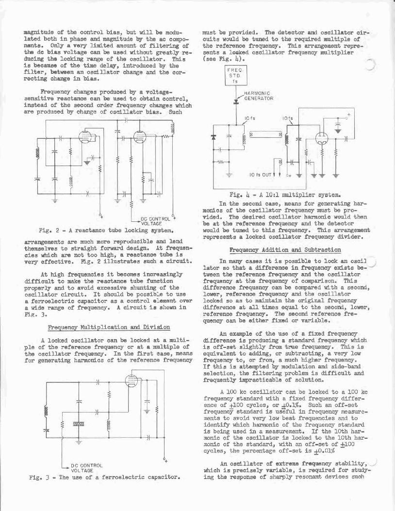
Frequeneg changes produced by a voltage- sensitim reactance can be used to obrtsln contro2, instead of the second m d e ~ Frequenw changes w h i c h are produced by change of osdllator bias. Such
Fig. 2 - A reactance tube l o c m g sjrstern.
arrangements are much more ~eproducible and lend themwlvea to 9trdght forward design. At hquen- efes vbich am not too Mgh, a reactance t u b i s verg sffeetive. Fig. 2 illustrates such a eircu3.t.
At high f'requencies f t b a r n s increasingly d i f f l~ul t to make the reaotanae t u b f'tmct-lon properly and to avoid exeessipa shunt* of the oscillator etr~rcuiL It should be possible to use a ferroelectric capaeftor as a cont ro l element over a wLde range of frequency. A circui t is shown in E g . 3.
Frequency MuTtipllcation and Mvldon
A locked o s c i l M o r can be locked at a mu1t5- ple of the reference frequency or at a multiple of the asclUator freqtlency. In the firat ease, means for generating hannodxs of the reference freqoency
L O C CONTROL VOLTAGE
Fig. 3 - The use of a ferroelectric capacttor.
nust be p r h d e d . The detector and osel_llator oir- c u i h w d d be tuned to the req-dred mnltlple of t h e refemnce frequency. This arrangement rep?%- sent5 a looked oscillator hquency multiplier (see Eg. 43.
- - . . - - .
Fig. 4 - A 10:l multiplier wsten, In %he second case, means f o r gemratlng har-
monics of the osci lLator ihqueney must be pro- d d e d . The desired o s c i l l a t o r harm0rd.c would then be at the reference A.eqwncg and the deteetaf would be tuned to t M s frequaneg. ThZs arrangement rspraserbs a locked oscillator fr%auency didder .
eequencg Add4ti on and Subtraction
In cases it i s possible to lock an oseL3 lator ao that a difference in Frequency e d s t s be- - tween the refe~ence frequenag and the oscillator frequency at the frequency o f eomparlson. This difference frequency can be compared WLth a second, lower, reference frequency aad t h e osefllator locked so as to maintain the oriLginal frequsnay difference at dl times equal t o t h e seeonri, lower, reference freguenw. The second reference fre- quency can be either Pixed o r variable.
An example of the use of a W d Frequency difference i s producing a standard freqnency wMch is off-set sught lg from t m e frequency. This is equivalent to adding, or subtract-lng, a v e v low frequency to, or from, a much Egher Preqwney. If tthis is attempted by modulation and side-band selection, t h e f i l ter ing problem is di f f i cu l t and frequently iqract icabla of solutLon.
A 100 kc osciUatos can be locked to a 100 kc frequency standard with a f k e d frequency differ- ence of 4 0 0 cycles, or ~0.1%. Such an off-set frequene standard is useful in frequency measure- ments to avoid .aery low beat frequencies and t o iderrt* which h m n i c of the frequency standard is be.ing used in a measurement. If t h e 10th har- m n l e of the oscillator i s locked to t h e lOth har- ,m& of She standmd, with an off-set o f 5 0 0 cycles, the percentage off-set; is f 0.01%
A n asdl lator of &rema f'requency s t a b i l i t y , _ M c h l a precisely variable, is required err study- ing the response of sharplg. resonant devices such

Fig. 5 - A n off-set frequency standaxd.
FREQ.
STD
Fig. 6 - Panel view of 10,000:1 multLplie
99 Kc
X - TUBE
1 AM PL.
I Kc
7
TUNED
DET
AUDIO OSC
0- 2 K c
1 0 0 K c -
, K c -
0 S C. 99-
101-Kc
DET DC CONTROL VOLTAGE
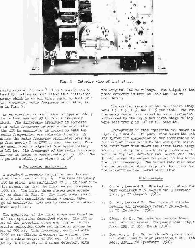
Fig. 8 - Interior view of last stage.
p a r t z c r y s t a l filters.4 Such a source can be iuced by locking an oscilla-tor at a difference pency which is at all times equal to that of a IT@, variable, audio frequency oscill~totor, as m in Fig. 5.
As an example, an a s c f i l a t n r o f approximately kc is beat aaaainst 99 kc f r o m a frequency ~clard. The d i f fere l~ce frequency is compared 1 an audio frequency interpolation oscillator the 130 kc oscillator is Locked, so t h a t t he audio frequencies are mintairled equal. By
xsting the audio frequency oscillztor over t he :e f r o m nearly 0 to 2000 cycles, the radio f ra- ~ c y oscillatar is adjusted f r o ~ n approxhately ;o 105 kc. The frequency or' t h e radio frequency i l lztor is Icnown to approximatsly k in 106. The A period s tab i l iky is about 4' in 107.
A particular Application
A standard frequency ~rrult ipl ier was designed, ?d on the ci:irGt of FLg. )L. The base frequency 100 kc which was multiplied by 10, in four suc-
sivre stages, se t h a t the final output frequency 1000 mc. The first three stages were essen-
l ly as shown in Fig. 2. The f i n a l stage was a :entric line osci1lator usjng a penci l tube. lee of osci3_latclr bias was by means of a cathode
The operation o f 2 . h ~ f ina l stags was baszd on off-set operation described above. The 100 mc
3ut of t h e preceding stage was t r ip l ed in two 2essive germanium diode mul.-tipliers, @vine an 3ut of ?OD mc. T h i s frequency, combined w L t h LOO0 rn o s c i l l a t o r frequency in a mixer, re-
k,s in a mixer output of 100 mc. This 100 mc pency is compared, In a phase detector , with
t h e o r ig ina l LOO mc vcltage. The output of the phase detector is used t o lack +,he 100 mc oscillztor.
The contrcl rangEs of the successive stage were 1.5, 0.5, 0.53 and 0.15 per cent. The rms f rewency deviations caused by noise (pr inc ipa l isl.troduced by the input and f i rs t stage m u l t i p l were less than 2 bi 107 on a l l outputs.
Photographs of this equipment are shown in Figs. 6 , 7 and 8, The pansl view s h w s the pat ing system for c o m ~ c t i o n of any combination of f o v output frequencies to t h e waveguide mixer. The first rear view shows the f i rs t t h r e ~ stage mde up i n strip form, each strip containjng a m o n k multiplier, detector and locked oscillztc In each stage the output frequency is ten times the input freq~ency. The second rear vtew show t h e two gernanim diocie t r ip le r s , the mixer and the concentric-line lccked oseilla.tor.
1. Cutler, Leonard S., "Locked oscillaters for test equiprent, lele-Tech and Elec t ron ic Ind . , p* '7 '1 ( Augus .t 1~54 ) .
2. Cutler, Leonard S ., "An improved d t rec t - reading vhf freque-ncp meter," Tele-Tech, p. 72 (~eptember 1952).
3 . Clapp, J. K., "P_n inductanc~-ca~acitance oecillztor of unu~ual frequency s tab i l i ty , Tq
Proc. m, 36:356 (Karch 19h8) .
4. Kaem-er, L. F., ItA variable-frequency nscil tcr s2,abilized t o high p r r c 5 s ~ o n , ~ ~ B e n Lab Hec . , XXVIlI 666 { ~ e b m ~ 1%0) .