Embed Size (px)
Citation preview
Source of Acquisition NASA Marshall Space Flight Centei
Thrust Stand for Electric Propulsion Pedormance Evaulation
Kurt A. Polzin,* Thomas E. Marlasic, Boris J. Stanojev, Amado Dehoyos, and Benjamin Spaun NASA-Marshall Space Flight Center
kturimdle, AL 35812
An electric propulsion thrust stand capable of supporting testing of thrusters having a total mass of up to 125 kg and producing thrust levels between 100 pN to 1 N has been developed and tested. The design €eatures a conventional hanging pendulum arm attached to a balance mechanism that converts horizontal deflections produced by the operating thruster into amplified vertical motion of a secondary arm. The level of amplification is changed through adjustment of the location of one of the pivot points linking the system. Response of the system depends on the relative magnitudes of the restoring moments applied by the displaced thruster mass and the twisting torsional pivots connecting the members of the balance mechanism. Displacement is measured using a non-contdct, optical linear gap displacement transducer and balance oscillatory motion is attenuated using a passive, eddy-current damper. The thrust stand employs an automated leveling and thermal control system. Pools of liquid gallium are used to deliver power to the thruster without using solid wire conenctions, which can exert undesirablc time-varying forces on the balance. These systems serve to eliminate sources of “zero-drift” that can occur as the stand thermally or mechanically shifts during the course of an experiment. An in-situ calibration rig allows for steady-state calibration before, during and after thruster operation. Thrust mcasuremcnls were carried out on a cylindrical I-Iall thruster that produces mN-level thrust. The measurements were very repeatablc, producing results that coniparc favorably with prcviously published performance data, but with considerably smaller uncertainty.
l?4CS numbers:
I. INTRODUCTION
Electric propulsion (ED) systems provide high specific impulse, but low thrust, relative to chemical propulsion systems. While chemical rocket thrust is generally mca- sured using load cells[l], the low thrust levels associ- ated with EP devices lead to thrust stands which more closely resemble sensitive laboratory mass scales, wherc physical displacement of one of the mechanical mern- bers in the balance system is used to infer the applied force. These balances are typically configured as either a hanging, inverted or torsional pendulum with the thruster mounted at the end of the pendulum arm.
The conventional hanging pendulum is the most sim- ple of the threc configurations and is highly stable when subjected to external perturbations. However, high sen- sitivity can only be attained with a long pendulum am, which may be impractical if the test facility (vacuum chamber) is sinall. Therefore, conventioiial hanging pen- dtdum thrust stands have been primarily used to test high thrust-to-weight, TIW, EP devices such as electrother- mal arcjets and microwave electrothermal thrustersl2,3]. Also, the displacement sensor is typically mounted on a separate reference structure that can (undesirably) move, independent of the pendulum niouuting structure, and produce erroneous results.
Inverted pendulum thrust stands are less stable but
Correspoiiding Author: Ktlrt.A.Polzia@i~?~~.gos
possess a greater sensitivity relative to the hanging pen- dulum configuration. They have been widely imple- mented to measure the performancc of thrusters over a broad range of T/W, including resistqjets, electrother- inal arcjets, MPD thrusters[4-6], liall thrustersl7-9], and ion thrusters. A problem for the inverted pendulum configuration is that its stability is a strong function of the stiffness of the (supporting) flexures, which can changc during the course of a test due to, for example, heating.
IJnlike both the conventional and inverted pendulum Configurations, the restoring force in the torsional pen- dulum configuration (which rotates about an axis that i s parallel to the gravity vector) can be made indepen- dent of the thruster mass. Consequently, torsional pen- dulum thrust stands provide the highest sensitivity, and have recently been implemented in micropropulsion per- formance evaluation[ 10- 161. They have also been shown to be effective in measuring the perform‘ance of pulsed thrusters[ 17-20]. The primary disadvantages of the tor- sional pendulum configuration are that the horizontal, asymmetric arrangement of its members can be difficult to configure within a vacuum chamber possessing lim- ited space and its sensitivity does not readily allow for testing of higher power thrusters.
We desciibe in this work a new thrust stand design: the Variable Amplitude Hanging Pendulum with Extended Range (VAHPER)[21]. This thrust stand i s a variant of the conventional pendulum, but it incorporates many novel features designed to enhance the quality of thrust data and the range of devices that can be tested. Specif- ically, the VAIWER thrust stand was designed to en-
https://ntrs.nasa.gov/search.jsp?R=20060025538 2018-11-03T08:15:29+00:00Z
POLZlN et al. VAKPER Thrust Stand
thruster mounting plate
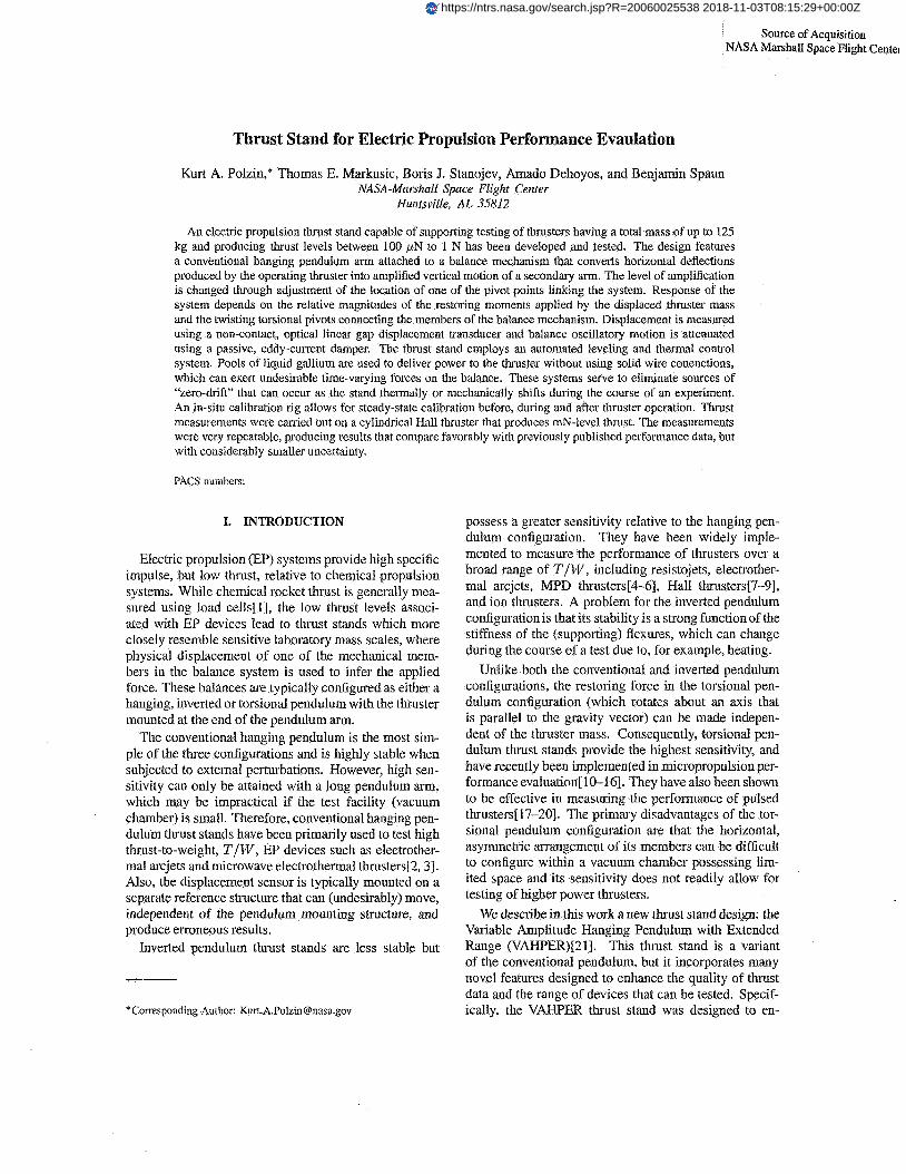
PIG. 1 : Schematic illustration of the assemhled VAHPBR thrust stand.
able ihrust measurement of electric thrusters weighing between 1-1 25 kg and producing thrust levels from 1 mN to over 1 N. This is acconiplished through a mechaicd linkage system that tr,anslates horizontal displacement into amplified verlical displacement. The system pro- vides for adjustable sensitivity though the adjustment of a single member. Displacement monitoring is performed on the vertically displaced member, which elimiiiatcs the need for a separate reference structure.
Pendulum-based thrust balances are susceptible to ‘zero-drift’, which means that when the thruster is turned off, the pendulum arm does not r e t m to its initial posi- tion. Several components and subsystems have been in- cluded in lhe VAI-IPER thrust stand design to mitigate the causes of zero-drift. These include low friction flexural pivot mounts, a non-contact rriometric position sensor, an on-board level control system, a thermal management system and an innovative method to feed power onto the thrust stand arm using liquid gallium pools.
In the next section we provide details regarding the de- sign of the thrust stand. Section III contains information about the thruster and facility used for the experiments
described in this paper. Data demonstrating the sensitiv- ity and thrust measurement capabilities of the VAHPER thrust stand are presented in section IV
11. VAHPER SYSTEM OVERVIEW
A schematic illustration of the VAHPER thrust stand is shown in Fig. 1. In the rest of this section, we describe in detail the various subsystem and the enhancement each component adds to the fidelity of the thnist measurement.
A. Balance Mechanism
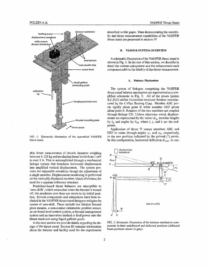
The system of linkages comprising the VANPFA thrust stand balance mechanism are represented as a sim- plified schematic in Fig, 2. All of the pivots (points B,C,D,E) utilize frictionless torsional flexures manufac- tured by the C-Flex Bearing Corp. Member ARC piv- ots rigidly about point B while member DEF pivots about point E. Rotation of the two members are coupled through linkage CD. Unless otherwise noted, displace- ments are represented by the vector dlj, member lengths by l i j and angles by Ollk where i, j, and k are the end- points.
Application of thrust T causes members ABC and IEF to rotate through angles a1 and a2, respectively, to the new position indicated by the primed (’) points. In this configuration, horizontal deflection d ~ - 4 ’ is con-
displacement cl transducer
(not to scale)
A’ A
FIG. 2: Schematic illustration of the balance mechanism com- ponents in their iindelleckd and deflected positions (deflected beam positions shown in grey).
2
POLZlN et al. VA€€PER Thrust Stand
verted to (amplified) vertical deflection d ~ ~ t , which is nieasured by the displacement transducer at the end of beam DEF. The VAHPER thrust stand pivots are mounted to the same structure as the displacement trans- ducer, thus eliminating the need for a separate (and prob- lenutic) reference structure. The trigonometric exercise of relating c l ~ ~ t to d ~ , ~ ~ ~ t is performed in Appendix 1 and results in the equation set
0 2
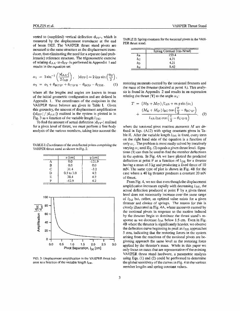
where all the lengths and angles are known in terms of the initial geometric configuration and are defined in Appendix 1. The coordinates of the endpoints in the VAHPER thrust balance are given in Table I. Given this geometry, the amount of displacement amplification (IdFFrI / IdAA,( ) realized in the system is plotted in in Fig. 3 as a function of the variable length I D E .
To find the amount of actual deflection l d ~ ~ t / realized Cor a given level of thrust, we must perform a free body analysis of the varjous members, taking into account the
= ff1 3- OBC’Df f OCtD’E - OBcD - OCDE, ( 1)
TABLE I: Coordinates of the undeflected points comprising the VAHPER thrust stand as shown in Fig. 2.
x [cml Y rcn11 :I”:” - 1 -3.2 21.9
31.4 0.5 to 3.0 4.2
30.4 4.2 4.2 -12.9 - I(_____-
loo I
0.0 0.5 1.0 1.5 2.0 2.5 3.0 Pivot Separation, IDE [cm]
FIG. 3: Displacement amplification in the VAHPER thrust bal- ance as a function of the variable length ID*.
TABLE 11: Spring constants for the torsional pivots in the VAH- PER thrust stand.
Spring Constant [cm-N/rad] 153.4
4.21 8.42
restoring moments exerted by the torsional flextures and the mass o f the thruster {located at point A). This analy- sis is found in Appendix 2 and results in an expression relating the thrust IT1 to the angle nl:
2’ = (A& -I- Mc,) /1.4p, 4- m gsin (01)
( h f E $. hfDt ) LBc cos (f - &jC!D,) , . (2) -
K IAH ID?& cos (2 - @(?WE)
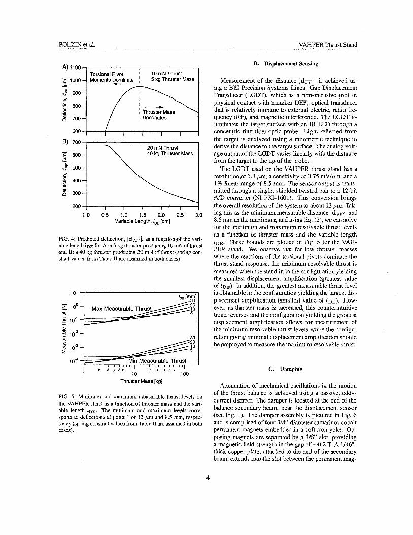
where the torsional pivot reaction moments :If are de- fined in ws. (A121 with spriag constants given in Fa- ble IT. After the variable length DE is fixed, every term on the right hand side OC the equation is a function of only al. The problem is most easily solved by iteratively varying a1 until Eq. (2) equals a given thrust level. Eqwa- tions (I) can then be used to find the membcr deflections in the system. In Fig. 4A we have plotted the predicted deflection at point F as a function of Z D E for a thruster having a mass of 5 kg and producing a fixed thrust of 10 mN. The same type of plot is shown in Fig. 4B for the case where a 40 kg thruster produces a constant 20 mN of thrust.
From Fig. 4, we see that even though the displacement amplification increases rapidly with decreasing I ~ E , the actual deflection produced at point F by a given thrust level does not necessarily increase over the same range of Z ~ E but, rather, an optimal value exists for a given tlxuster and clioice of springs. The reason for this is clearly illustrated in Fig. 4A, where niomeuts exerted by the torsional pivots in response to the motion induced by the thruster begin to dominate the thrust stand’s re- sponse as we decrease Z D E below 1.5 cm. Even in Fig. 4B where the thruster is significantly heavier, we observe the deflection curve beginning to peak as 1 DE approaches 5 mm, indicating that the resloring forces in the system arising from the reactions of the torsional pivots are be- ginning approach the same level as the restoring force applied by the thruster’s mass. While in this paper we only focus on cases that are representative of the existing VAHPER thrust stand hardware, a parametric analysis using Eqs. (1) and (2) could be performed to determine the global sensitivity of the curves in Fig. 4 to the various member lengths and spring constant values.
3
POLZIN et al. VAI-IPER Thrust Stand
A) 1100
5 1000
2 900 e
800
3 - 1 700 % =
Torsional Pivot I 10 mN Thrust Moments tominate I 5 kg Thruster Mass
20 mN Thrust 40 kg Thruster Mass
u
L +I" 500
0.0 0.5 1.0 1.5 2.0 2.5 3.0 Variable Length, IDE [cm]
FIG. 4: Predicted deflection, IdFFtj, as a function of the vari- able length for A) a 5 kg thruster producing 10 mnN of tl~rust and B) a 40 Ig thrustcr producing 20 mN of thrust (spring con- slaut values from Tablc I1 are assumed in bolh cases).
10' 'DE [mml If 30 20
1 10 100 Thruster Mass [kg]
FIG. 5: Minimum and maximum nicdsurable thrust levels on the VAHPER stand as a function of thruster mass and the vari- able length /DE. The minimum and maxinium levels corre- spond to deflections at point F of 13 p n and 8.5 mm, respec- tivley (spring constant values from ydbk 11 are assumed in both cases).
B. Displacement Sensing
Measurement of the distance JdFpi is achieved us- ing a BE1 Precision Systems Linear Gap Displacement Transducer (LGDT), which is a non-intrusive (not in physical contact with member DEF) optical transducer that is relatively immune to external electric, radio fre- quency (RF), and magnetic interference. The LGDT il- luminates the target surface with an IR LED through a concentric-ring fiber-optic probe. Light reflected from the target is analyzed using a ratiometric technique to derive the distance to the target surface. The arialog volt- age output of the LGDT varies linearly with the distance from the target to the tip of the probe.
The LGDT uscd on the VMIPER thrust stand has a resolution of 1.3 pm, a sensirivity of 0.75 mV/,um, and a 1% linear range of 8.5 mm. The sensor output is trans- mitted through a single, shielded twisted pair to a 12bit AID converter (NI PXI-1601). This conversion brings the overall resolution of the system to about 13 pm. Tak- ing this as the minimum measurable distance IdFFtI and 8.5 mn as the inaximmq and using Eq. (2), we can solve for the minimum and maximum resolvable thrust levels as a function of' thruster mass and the variable length l n ~ . These bounds are plotted in Fig. 5 for the VAH- PER stand. We observe that for low thruster masses where the reactions of the pivots dominate the thrust stand response, the 1 resolvable thrust is measured when the stand in in &he configuration yielding the sniallest displacement amplilication (greatest value of ID^). In addition, the greatcst measurable thrust level is obtainable in the configuration yielding the largest dis- placement amplification (smallest value of [DE). How- ever, as thruster mass is increased, this counterintuitive lrend reverses and the configuration yielding the greatest displacement amplification allows for measuremetit of the minimum resolvable Ihrust levels while the coniigu- ration giving minimal displacement amplification should be employed to measure the maximum resolvable thrust.
C. Damping
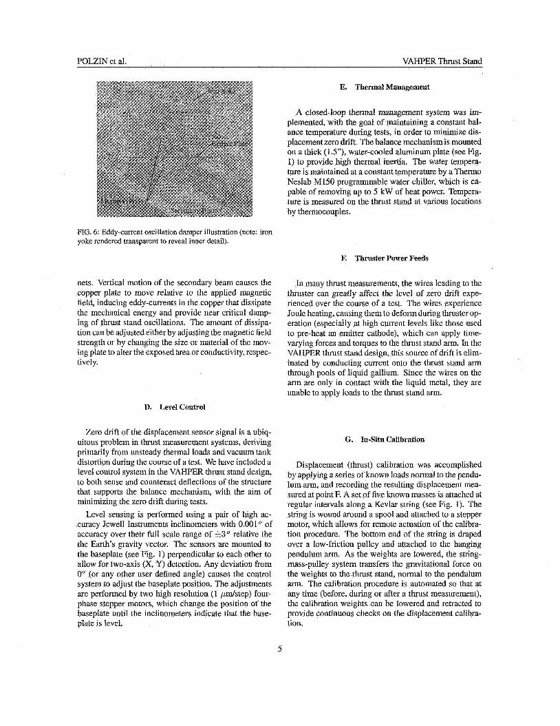
At tenuation of mechanical oscillations in the motion of the thrust balance is achieved using a passive, eddy- current damper. The damper is located at the end of the balance secondary bean, near the displacement sensor (see Fig. I). The damper assembly is pictured in Fig. 6 and is comprised of four 3/8"-diametcr samarium-cobalt permanent magnets embedded in a soft iron yoke. Up- posing magnets are separated by a 1/8' slot, providing a magnetic field strength in the gap of -0.2 T. A 1/16"- thick copper plate, attached to the end of the secondary beam, extends into the slot between the permanent mag-
4
POLZlN et al. VAHPER Thrust Stand
E. Thermal Management
A closed-loop thermal management system was im- plemented, with the goal of maintaining a constant bal- ance temperature during tests, in order to minimize dis- placement zero drift. The balance mechanism is mounted on a thick (IS"), water-cooled aluminum plate (see 'Fig. 1) to provide high thermal inertia. The water tempera- ture is maintained at a coiistant temperature by a Therm0 Neslab M150 programmable water chiller, which is ca- pable of removing up to 5 kW of heat power. Tempera- ture is measured on the thrust stand at various locations by thermocouples.
FIG. 6: Eddy-current oscillation damper illustration (note: iron yokc rcndcred transparent to reveal inner detail).
F. Thruster Power Feeds
nets. Vertical motion of the secondary beam causes the copper plate to move relative to the applied magnetic field, inducing eddy-currents in the copper that dissipate the mechanical energy and providc near critical damp- ing of thrust stand oscillations. The amount of dissipa- tion can be adjustedeither by adjusting the magnetic field strength or by changing the size or material of the mov- ing plate to alter the exposed area or conductivity, respec- tively.
D. Level Control
Zero drift of the displacement sensor signid is a ubiq- uitous problem in thrust measurement systems, deriving primarily from unsteady thermal loads and vacuum tank distortion during the course of a test. We have included a level control system in the VAHPER thrust stand design, to both sense and counteract deflections of the structure that supports the balance mechanism, with the aim of minimizing the zero drift during tests.
Level sensing is performed using a pair of high ac- curacy Jewel1 Instruments inclinometers with 0.001 of accuracy over their full scale range of k3" relative the the Earth's gravity vector. The sensors are mounted to the baseplate (see Fig. 1) perpendicular to each other to allow for two-axis (X, Y) detection. Any deviation from 0' (or any other user defined angle) causes the control system to adjust the baseplate position. The adjustments are performed by two high resolution (1 pds tep) four- phase stepper motors, which change the position of the basepIate until the inclinometers indicate that the base- plate is level.
In many thrust measurements, the wires leading to the thruster can greatly affect the level of zero drift expe- rienced over the course of a test. The wires experience Joule heating, causing them to deform during thruster op- eration (especially at high current levels like those used to pre-heat an emitter cathode), which can apply time- varying forces and torques to the thrust stand arm. In the VAHPER thrust stand design, this source of drift is elim- inated by conducting current onto the thrust stand arm through pools of liquid gallium. Since the wires on the arm are only in contact with the liquid metal, they are unable to apply loads to the thrust stand a m .
G. In-Situ Calibration
Displacement (thrust) calibration was accomplished by applying a series of known loads normal to the pendu- lum arm, and recording the resulting displacement mea- sured at point E A set of five known masses is attached at regular intervals along a Kevlax string (see Fig. 1). The string is wound around a spool and attached to a stepper motor, which allows for remote actuation of the calibra- tion procedure. The bottom end of the string is draped over a low-friction pulley and attached to the hanging pendulum arm. As the weights are lowered, the string- mass-pulley system transfers the gravitational force on the weights to the thrust stand, nornial to the pendulum arm. The calibration procedure is automated so that at any time (before, during or after a thrust measurement), the calibration weights can be lowered and retracted to provide continuous checks on the displacement calibra- tion.
5
POLZIN et al. VAI-PER Thrust Stand
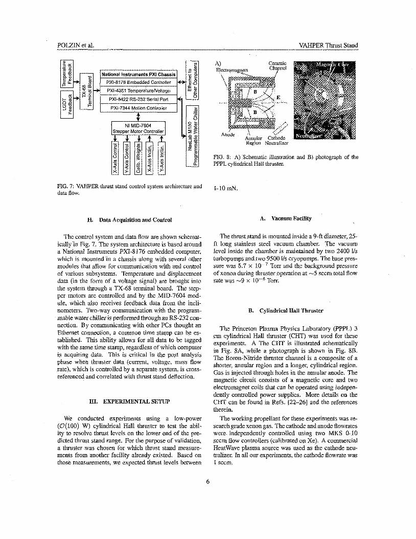
FIG. 7: VAHFER thrust stand control system architecture and data flow.
H. Data Acquisition and Coritrol
The control system and data flow are shown schemat- ically in Fig. 7. The system architecture is based around a National Instrurnents PXI-8 2 76 embedded computer, which is mounted in a chassis along with several other modules that allow for communication with and control of various subsystems. 'Temperature and dispiaccnient data (in the forni of a voltage signal) are hrought into the system through a TX-68 terminal board. The step- per motors are controlled and by the MID-7604 mod- ule, which also receives feedback data froin the incli- nometers. Two-way communication with the program- mable water chiller is performed through an 138-232 con- nection. By communicating with other PCs thought an Ethernet connection, a common time stamp can be es- tablished. This ability allows for all data to be tagged with the same time stamp, regardless of which computer is acquiring data. This is critical in the post anaIysis phase when thruster data (current, voltage, inass flow rate), which is controlled by a separate system, is cross- referenced and correlated with thrust stand deflection.
1x1. EXl'EKIMEXTAL SETUP
We conducted experiments using a low-power (O(lO0) W) cylindrical Hall thruster to test the abil- ity to resolve thrust levels on the lower end of the pre- dicted thrust stand range. For the purpose of validation, a thruster was chosen for which thrust stand nieasure- ments from another facility already existed. Based on those measurements, we expected thrust levels between
Ceramic
Anode A h a Cathode Region Neutraliza
FIG. 8: A) Schematic illustration and B) photograph of the PPPL cylindrical Hall thruster.
1-10 mN.
A. Vacuum Facility
The thrust stand is mounted inside a 9-ft diameter, 25- ft long stainless steel vacuum climber. The vacuum level inside the chamber is maintained by two 2400 U s turbopumps and two 9500 1/s cryopumps. The base pres- sure was 5.7 x lov7 Torr and the background pressure of xenon during thruster operation at -5 sccni total flow rate was -9 x Torr.
R. Cyliiidiical IIdl Thruster
The Princeton Plasma Physics Laboratory (PPPL) 3 cm cylindrical Hall thruster (CHT) w a used for these experiments. A The CHT is illustrated schematically in Fig. 8A, while a photograph is shown in Fig. 8B. The Boron-Nitride thruster channel is a composite of a shorter, annular region and a longer, cylindrical region. Gas is injected through holes in the annular anode. The magnetic circuit consists of a magnetic core and two electromagnet coils that can be operated using indepen- dently controlled power supplies. rMore details 011 the CHT can be found in Refs. [22-261 and the references therein.
The working propellant for these experiments was re- search grade xenon gas. The cathode and anode flowrates were independently controlled using two MKS 0-10 sccm flow controllers (calibrated on Xe). A colnmerckd HeatWave plasma source was used as the cathode neu- tralizer. In all our experiments, the cathode flowrate was 1 sccm.
6
POLZIK et al. VAHPER Thrust Stmd
IV. EXPERIMENTAL RESULTS
A. Thrust Stand Calibration
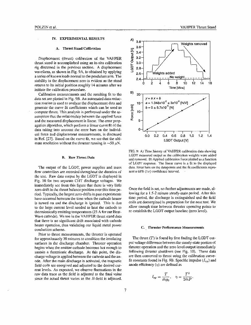
Displacement (thrust) calibration of the VAHPER thrust stand is accomplished using an iu-situ calibration rig discussed in the previous section. A displacement waveform, as shown in Fig. 9A, is obtained by applying a series of known loads normal to the pendulum arm. The stability in the displacement zero is evident as the stand returns to its initial position roughly 14 minutes after we initiate the calibration procedure.
Calibration nieasureinents and the resulting fit to the data set are plotted in Fig. 9B. An automated data reduc- tion routine is used to analyze the displacement data and generate the curve Et coefficients which can be used to compute thrust. This analysis is performed under the as- sumption that the relationship between the applied force and the measured displacement is linear. The crror prop- agation algorithm, which perform a linear curve tit of the data taking into account the error bars on the individ- ual force and displacement measurements, is discussed in Ref. [27]. Based on the curve fit, we sce that the ulti- mate resolution without the thruster running is -50 1.~3.
A) 3.8 - 3.6 5 3.4 3
3.2 2 3.0 3 2.8
2.6 2.4
-I
0 2 4 6 8 10 12 14 16 Time [Mins]
I I I I I I I 0.0 0.2 0.4 0.6 0.8 1.0 1.2 1.4
LGDT Output [VI
1%. Kaw Thrust Data
The output of the LGDT, power supplies and mass flow cotitrollers are recorded throughout the duration of the test. Raw data output by the LGDT is displayed in Pig. 10 for two separate CHT discharge voltages. We immediately see from this figure that there is very little zero-drift in the thrust balance position over this time pe- riod. Typically, the largest zero-drifts in past experirnents have occurred between the time when the cathode heater is turned on aid the discharge is ignited. This is due to the large current level needed to heat the cathode to therrnionically emitting temperatures (23 A for ow Heat- Wave cathode). We see in the VAITPER thrust stand data that there is no significant clrift associated with cathode heater operation, thus validating our liquid metal power conduction scheme.
Prior to thrust measurements, the thruster is operated for approximately 30 ininutcs to condition the insulating surfaces in the discharge chamber. Thruster operation begins when the emitter cathode becomes hot euough to sustain a thermionic discharge. At this point, the dis- charge voltage is applied between the cathode and the an- ode. After the main discharge is activated, the magnetic field coils are energized and adjusted to the desired cur- rent levels. As expected, we observe fluctuations in the raw data trace as the field is adjusted to the final value since the actual thrust varies as the B-field is adjusted.
FIG. 9: A) Time history or VAI-PER calibration data showing LGIX mcasured output as the calibration weights were added and removed. B) Applied calibration force plotled as a function of LGDT rcsponse. Tlic linear curve is a fit to the displayed data. Error bars on the datapoints and the fit coefficients repre- sent a 08% (1 u) confidence interval.
Once the field is set, no further adjustments are made, al- lowing for a 1.5-2 minute steady-state period. Aiier this time period, the discharge is extinguished <and the field coils are deenergized in preparation for the next test. We allow enough time between thruster operating points to re-establish the LGDT output baseline (zero level).
C. Thruster Performance Measurements
The thrust (T) is found by first finding the LGDT out- put voltage difference between the steady-state portion of thruster operation and the zero level output immediately following thruster shutdown (see Fig. 10). These data are then converted to thrust using the calibration curve- fit constants found in Fig. 38. Specific impulse (Isp) and anode efficiency (q) are defined as
7
POLZIN et al. VAHPER Thrust Stand
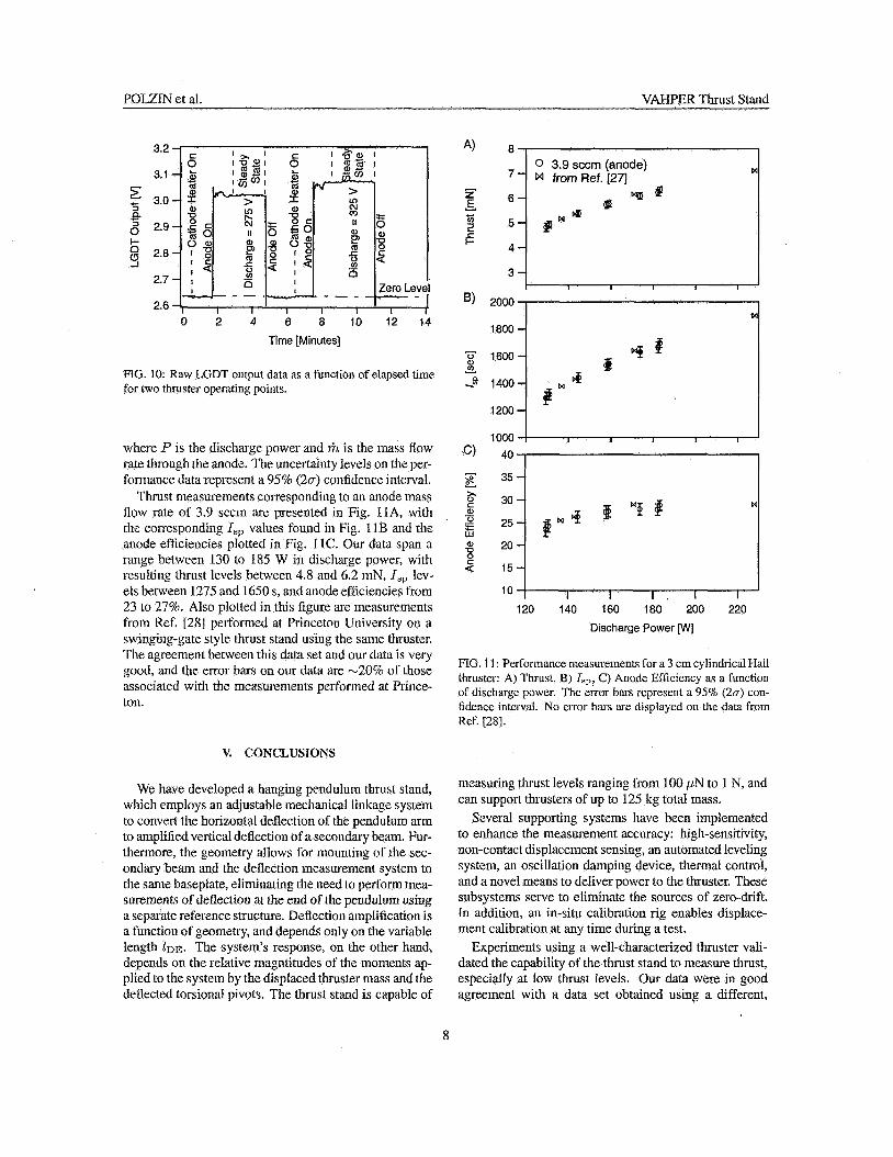
FIG. 10: Raw LGDT output data as a function of elapsed time for two thruster operating points.
where P is the discharge power and riz is the mass flow rate through the anode. The uncertainty levels on the per- formance data represent a 95% ( 2 ~ ) confidence interval.
Thrust measurements corresponding to an anode mass flow rate of 3.9 sccin are presented in Fig. 1 lA, with the corresponding Zsp values found in Fig. 1 1 B and the anode efficiencies pIotted in Fig. 11 c. our data span a range between 130 to 185 W in discharge power, with resulting thrust levels between 4.8 and 6.2 mN, I,, lev- els between 1275 and 1650 s, and anode efficiencies from 23 to 27%. Also plotted in this figure are measurements from Ref. 1281 performed at Princeton University on a swinging-gate style thrust stand using the same thruster. The agreement between this dala set and our data is very good, and the error bars on our data are -20% of those associated with the measurements perfomled at Prince- ton.
V. CONCLUSIONS
We have developed a hanging pendulum thrust stand, which employs an adjustable mechanical linkage system to convert the horizontal deflection of the pendulum arm to amplified vertical deflection of a secondary beam. Fur- thermore, the geometry allows for mounting of the sec- ondary beam and the deflection measurement system to the same baseplate, eliminating the need to perform mea- surements of defleclion at the end of the pendulum using a separate reference structure. Deflection amplification is a function of geometry, and depends only on the variable length ZDF,. The system's response, on the other hand, depends on the relative magntitudes of the moments ap- plied to the system by the disphced thruster mass and the deflected torsional pivots. The thrust stand is capable of
0 3.9 sccm (anode)
2000
1800 1
1000 ! I I I I I
35 1
120 140 160 180 200 220
Discharge Power [w]
FIG. 11 : Perfoiinance nieasureinenis for a 3 cm cylindrical Hall thruster: A) Thrust, B) I,,, C ) Anode Efficiency as a function of discharge power. The error bars represent a 95% ( 2 ~ ) con- fidence interval. No error bars are displayed on the data from Ref. [28] .
measuring thrust levels ranging from 100 p N to 1 N, and can support thrusters of up to 125 kg total mass.
Several supporting systems have been implemented to enhance the measurement accuracy: high-sensitivity, non-contact displacement sensing, an automated leveling system, ati oscillation damping device, thermal contml, and a novel means to deliver power to the thruster. These subsystems serve to eliminate the sources of zero-drift. i n addition, an in-situ calibration rig enables displace- ment calibration at any time during a test.
Experiments using a well-characterized thruster vali- dated the capability of the thrust stand to measure thrust, especially at low thrust levels. Our data were in good agreement with a data set obtained using a different,
8
POLZlX et al. VAHPER l b i s t Stand
well-characterized thrust stand, the error bars on our data set were only 20% of those found in the literature, demonstTating the effectiveness of the systems listed in the previous paragraph.
Acknowledgments
We acknowledge Dr. Mark Cox for the balance mech- anism design implemented in the VAHPER thrust stand. We appreciate the support of tlie Propulsion Research Center management, Drs. George Schmidt and Charles Schafer. We gratefully acknowledge the contributions of the PRC technical support st&. Doug Davenport, Tommy Reid, Doug Galloway, Keith Chavers and Ron- dal Boutwcll. Wc also extcnd our gratitude to students Chris Dodson and Jeff Gross, and to Freida Lowery in the MSFC Business Developinent Office. Thrust me+ surements were performed under Space Act Agreement NAS8-05791 and supported by the MSFC Technology Transfer Office.
APPENDIX: THEOItETICAL ANALYSIS OF BALANCE M E C W I S M
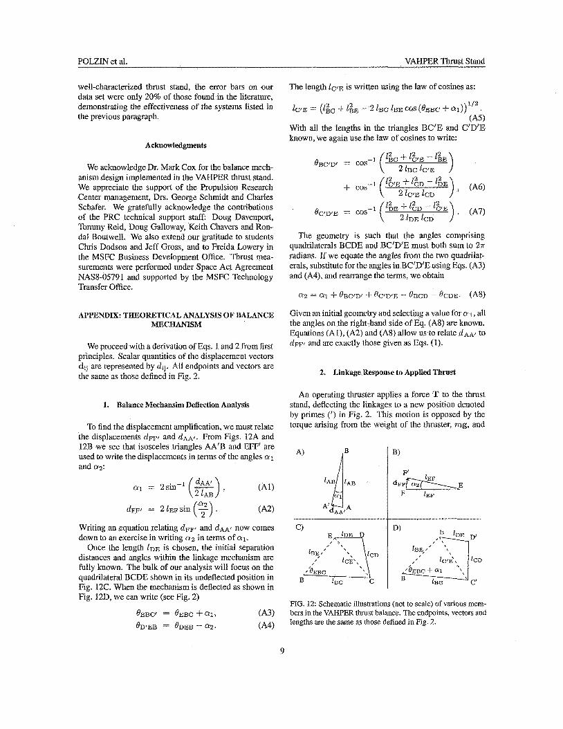
We proceed with a derivation of Eqs. 1 and 2 from first principles. Scalar quantities of the displacement vectors dij are represented by dij. All endpoints and vectors are the same as those defined in Ag. 2.
1. Balance Mechansim Deflection Anaiysis
To find the displaccrneiit amplificalion, we must rchte the displacements d ~ p and dAAf. From Figs. 12A and 12R we see that isosceles triangles AA‘B and EFF’ are used to write the displacements in terms of the angles a 1 atld 02:
Writing an equation relating d ~ p and dA.41 now comes down to an exercise in writing 0 2 in terms of a1.
Once the length I D F , is chosen, the initial separation distances and angles within the linkage mechanism are fully known. The bulk of our analysis will focus on the quadrilateral BCDE shown in its undeflected position in Fig. 12C. When the mechanism is deflected as shown in Fig. 12D, we can write (see Fig. 2)
& B C ~ = O m C + ai, (A3) $D!fiB = -&2. ( A 4
The length L C ’ E is written using the law of cosines as:
&YE = (I& f - 2 ZBC IBE COS (&Be $. (A.3
With all the lengths in the triangles BC’E and C‘D’E known, we again use the law of cosines to write:
The geometry is such that the angles comprising quadrilaterals BCDE and BC’D’E must both sum to 27i radians. Tf we equate the angles from the two quadrilat- erals, substitute for the angles in BC’D’E using Eqs. (A3) and (A4), and rearrange the terms, we obtain
fl2 $. O B < ; ~ D ~ @<?I>!E - ORCI) - OCDE. (AS)
Given an initial geometry and selecting a value for N 1, all the angles on the right-hand side of Eq. (AS) are known. Equations (A I), (A2) and (AS) allow us to relate ~ A A , to ~ F F ‘ and are exactly those given i ls Eqs. (1).
2. Linkage Response to Applied Thrust
An operating thruster applies a force T to the thrust stand, deflecting the linkages to a new position denoted by primes (’) in Fig. 2. This motion is opposed by the torque arising From the weight of the thruster, m g , and
I
FIG. 12: Schematic illustrations (not to scale) of various mem- bers in the VAI-PER thrust balance. The endpoints, vectors and lengths are the same as hose defined in Fig. 2.
9
POLZIN et al. VAHPEK Thrust Stand
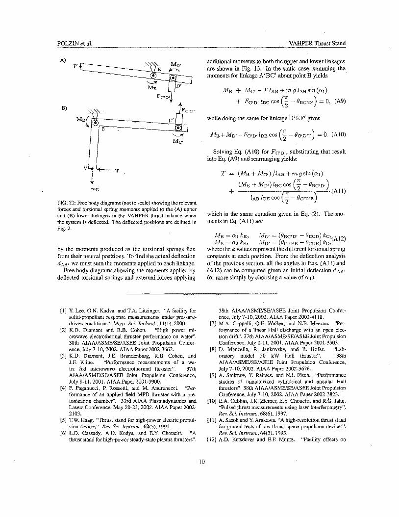
FIG. 13: Free body diagrams (not to scale) showing the rclevant forces and torsional spring moments applied to the (A) upper and (B) lower linkages in the VAHPER thrust balance when thc system is deflcctcd. The deflected positions are defined in Fig. 2.
by the moments produced as the torsional springs flex from their neutral positions. To find the aclual deflection Q!.&A, we must sum the moments applied to each linkage.
Free body diagrams showing the moments applied by deflected torsional springs and external forces applying
additional moments to both the upper and lower linkages are shown in Fig. 13. h the static case, sUmmiug the moments for linkage A‘BC‘ about point I3 yields
n ME i k ’ f ~ r - Fc~D, I D E COS (- - BG’DTE) = 0. (A10) 2
Solving Eq. (A10) for FcQ,, substituting that result into Eq. (A9) and rearranging yields:
T = (I%& + i ~ ~ ~ l ) / 1 ~ 1 l + 7 ~ ~ g s i l - i ( a l )
(ME + A h l ) ZBC cos (; - BRG‘D’) .(A1 1 ) n +
IN3 IDF; cos (5 - oC/Dfii)
which is the same equation given in Eq. (2). The mo- irients in Eq. (A I l ) are
~ $ 3 = 0 1 k.13, M C ~ = (eLlCJDl - oBCD) kc;,(r112) MJy = (t?pn,f, - &DE:> ICD:
where the k values represent the different torsional spring constants at each position. From the deflection analysis of the previous section, all the angles in Eqs. (AI 1) and (A12) can be computed given an initial deflection r i . ~ r (or inore simply by choosing a value of n 1 ).
M E = 8 2 k E :
[I] Y. LCC, G.N. Kudva, and T.A. Litzinger. “A facility for solid-propellant response measurements under pressure- driven conditions”. Meus. Sci. Technol., 11( I) , 2000.
“High power mi- crowave clectrolhermal thruster pcrformance on water”. 38th AIAA/ASkIE/SEYASEE Joint Propulsion Confer- cncc, July 7-10,2002. AIAA Paper 2002-3662.
[31 K.D. Diamant, J.E. Brandenburg, R.R. Cohen, and J.F. Kline. “Performanec measurcnients of a wa- ier fed microwave electrothermal thruster“. 371h AIAAIASMFYSWASEE Joint Propulsion Conference, July 8-11,2001. AIAA Paper 2001-3900.
‘Per- formance of an applied field MPD thruster with a pre- ionization chamber”. 33rd AIAA Plasmadynamics and Lasers Conference, iMay 20-23, 2002. ALAA Paper 2002- 2103.
[SI T.W. Haag. “Thrust stand for high-power electric propul- sion devices”. Rev. Sci. Instrum., 62(5), 199 1.
[6] L.D. Cassady, A.D. Kodys, and E.Y. Choueiri. “A thrust stand for high-power steady-state plasma thrusters”.
[2] K.D. Diamant and R.B. Cohen.
[4] F. Paganucci, P. Rossetti, and M. Andrcnucci.
38th AIANASMWSWASEE Joint Propulsion Confer- ence, July 7-10,2002. AIAA Paper 2002-41 18.
[7] M.A. Cappclli, Q.E. Walker, and X.B. Meezan. “Pcr- formance of a linear I-Iall discharge with an open elec- tron drift”. 37th AlANASMWSWASEEJoint Propulsion Conference, July 8-1 1,2001. AIAA Paper 2001-3503.
[SI D. Manzella, R. Jankovsky, and R. Hofer. ‘ lab- oratory model SO kW Hall thrustei‘. 38th AIAAlAShElSElASEE Joint Propulsion Conference, July 7-10.2002. AIAA Paper 2002-3676.
[9] A. Smirnov, Y. Raitses, and N.J. Fisch. “Performance studies of miniaturized cylindrical and annular Hall thrusters”. 38th AIAAIASMEISWASEE Joint Propulsion Conference, July 7-10,2002. AIAA Paper 2002-3823.
[IO] E.A. Cubbin, J.K. Ziemer, E.Y. Choueiri, and R.G. Jahn. “Pulsed thrust measurements using laser inteiferometry”. Rev. Sei. Instrum., 68(6), 1997.
[ 1 I] A. Sasoh and Y. Arakawa. “A high-resolution thrust stand for ground tests of low-thrust space propulsion devices”. Rev. Sci. Instrum., 64(3), 1993.
Tacility cffects on [12] A.D. Ketsdevcr and E.P. Muntz.
10
POLZIN et al. VAHPER Thrust Stand
performance measurements of micropropulsion systems”. 37th AIAA/ASME/SWASEE Joint Propulsion Confer- ence, July 8-1 1, 2001. AIAA Paper 2001-3335.
[ 131 A.D. Ketsdever, A.A. Green, and E.P. Muntz. “Momen- tum flux mcasurements from under expanded orifices: Applications for microspacecraft systems". 39th A I M Aerospace Sciences Meeting, Jan. 8- 1 I , 2001. AIAA Pa- per 2001-0502.
1141 B. Recd. ‘Decomposing solid micropropulsion nozzle performance issues’’. 3 1 st AIAA Aerospace Sciences Meeting, Jan. 6-9,2003. AIAA Paper 2003-0672.
[15] W.D. Willis 111, C.M. Zakrzwski, and S.M. Merkowia. “Development of a thrust stand to mcct LISA mission re- quirements”. 38th AIANASMWSWASEE Joint Propul- sion Conference, July 7-10, 2002. AIAA Paper 2002- 3820.
11 61 J.K. Ziemcr. ‘Zascr ablation microthruster technology”. 33rd AIAA Plasmadynamics and Lascrs Conferencc, May 20-23,2002. AlAA Paper 2002-2153.
[17] T.W. Hnag. “PPT thrust stand”. 31st AIAA/ASME/SE/ASEE Joint Propulsion Confcrcncc, July 10-12, 1995. AIAA Paper 95-2917.
1181 K.W. Stark, T. Dennis, D. McHugh, andT. Williams. “De- sign and development of a micropound extended range thrsut stand”. Technical Report NASA TN D-7029, Aug. 1971.
1191 T.W. Iiaag. “Thrust stand Cor pulscd plasma thrustcrs”. Rei]. Sci. Instrum., 68(5), 1997.
[20] 7:E. Markusic, K.A. Polzin, E.Y. Choueiri, M. Kcidar, LD. Boyd, and N. Lepsctz. “Ablative 2-pinch pulsed plasma thruster”. J. Propu1.s. Power, 21(3):392-400,
2005. 1211 T.E. Markusic, J.E. Jones, and M.D. Cox. “Thrust stand
for electric propulsion performance evaIuation”. In dot” A1XALASMWSAlYASE.E Joint Propulsion Conference, Ft. Lauderdale, FL, July 11-14,2004. AIAA 2004-3441.
[22] Y. Raitses and N.J. Fisch. ‘Twametric investigations of a nonconventional hall thruster”. Phys. Plasmas, 8(5):2579, May 2001.
[23] A. Smirnov, Y. Raitses, and N.J. Fisch. ‘Tammetric in- vestigations of a miniaturized cylindrical and annular hall thrusters“. J. AppZ. Phys., 92( 10):5673, Nov. 2002.
[24] A. Smimov, Y. Raitses, and N.J. Fisch. ‘%Enhanced ion- ization in the cylindrical hall thruster”. ,/. Appf. Plzys., 94(2):852, July 2003.
[25] A. Smirnov, Y. Raitses, and N.J. Pisch. “Plasma measure- ments in a 100 w cylindrical hall thruster”. J. AppZ. Phys., 95(5):2283, Mar. 2004.
es, and N.J. Fisch. “Electron cross- field transport in a low power cylindrical hall thruster”. Phyys. Plasmas, 11( 1):4922, Nov. 2004.
[27] D. York, N.M. Evensen, M.L. Martinez, and J.D.B. Dcl- gado. “LJnified equations for the slope, intercept, and
best straight line”. Am. .I. Phy,s.,
1281 A. Smirnov, Y. Raitses, and Fisch. “The effect of magnetic field on the performance of low-power cylindri- cal Wall thiusters”. 29th Intcrnational Electric Propulsion Confcrencc, Oct. 31 - Nov. 4, 2005’. IEPC Paper 2005- 099.
[26] A. Smirnov, Y. R
I 1