Embed Size (px)
Citation preview

Ductile Iron Pipe Research Association
Thrust Restraint
CA-NV Section AWWAAnnual Fall Conference
October 22, 2014

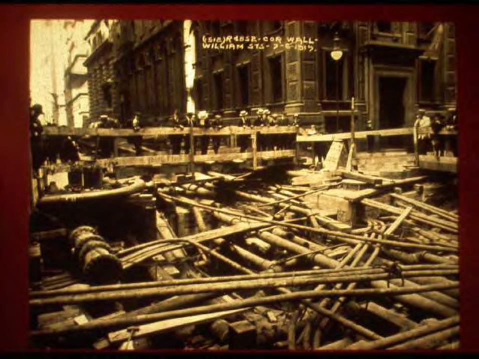
1915

DIPRA Member Companies

AWWA Standards
ANSI/AWWA C104/A21.4 Cement-Mortar LiningsANSI/AWWA C105/A21.5 Polyethylene Encasement
ANSI/AWWA C110/A21.10 Ductile-Iron and Gray-Iron FittingsANSI/AWWA C111/A21.11 Rubber-Gasket JointsANSI/AWWA C115/A21.15 Flanged Ductile-Iron PipeANSI/AWWA C116/A21.16 Fusion-Bonded Epoxy Coatings for FittingsANSI/AWWA C150/A21.50 Thickness DesignANSI/AWWA C151/A21.51 Ductile-Iron Pipe, Centrifugally CastANSI/AWWA C153/A21.53 Ductile-Iron Compact Fittings
ANSI/AWWA C600 Installation of Ductile-Iron Water Mains
Regional Engineer Program
Region 1
Paul H. Hanson, P.E.
Regional Director
NACE Certified Corrosion Specialist

Regional Engineer Program
Region 2
Allen H. Cox, P.E.
Regional Director
NACE Certified Corrosion Specialist

Regional Engineer Activities
Direct Calls
Technical Presentations
Engineering Investigations
Technical Assistance
Professional Groups

DIPRA Website(www.dipra.org)
RestrainingThrust Forces

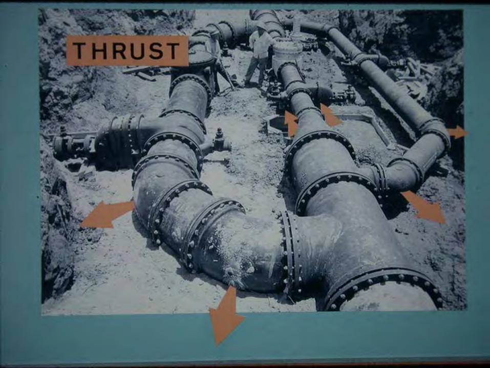
Forces Causing Thrust
Static forces(Internal pressure)
Dynamic forces(Fluid velocity)

Thrust Force
Straight Run
PA PA

Thrust Force
Bend
2PA Sin(/2)

Resultant Thrust: 90° Bend
NominalPipe Size
(in)
ThrustForce(lbs)
6 7,93212 29,03024 110,90136 244,39648 429,95664 718,506
Pressure at 150 psi
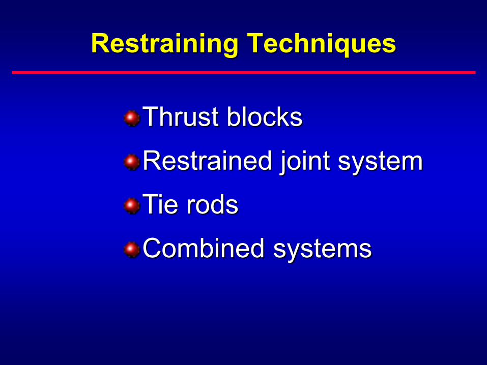
Restraining Techniques
Thrust blocksRestrained joint systemTie rodsCombined systems

Types of Thrust Blocks
BearingGravity

Bearing Thrust Block
Bearing Area (ft2) =Safety Factor • Thrust Force (lbs)
Bearing Capacity of Undisturbed Soil (lbs/ft2)
Undisturbed Soil Bearing Area
45°45°
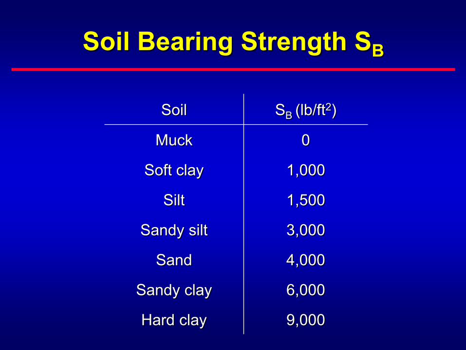
Soil Bearing Strength SB
Soil SB (lb/ft2)
Muck 0
Soft clay 1,000
Silt 1,500
Sandy silt 3,000
Sand 4,000
Sandy clay 6,000
Hard clay 9,000
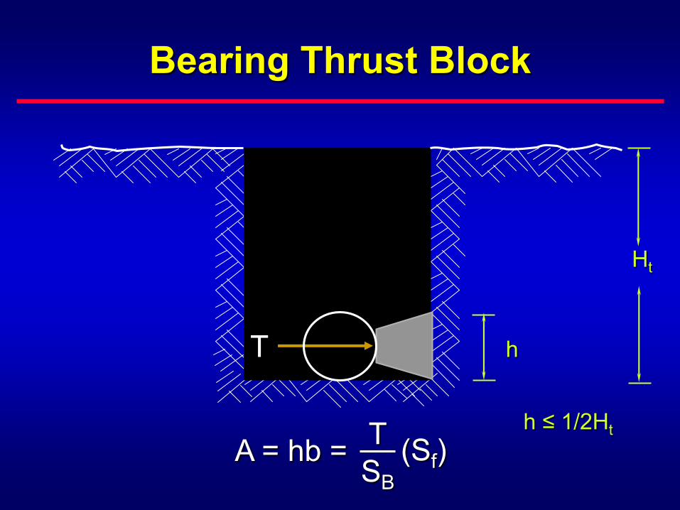
Bearing Thrust Block
Ht
h
h ≤ 1/2Ht
T
A = hb = TSB
(Sf)
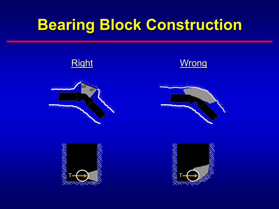
Bearing Block Construction
Right Wrong
45°45°
T T

Thrust Restraint
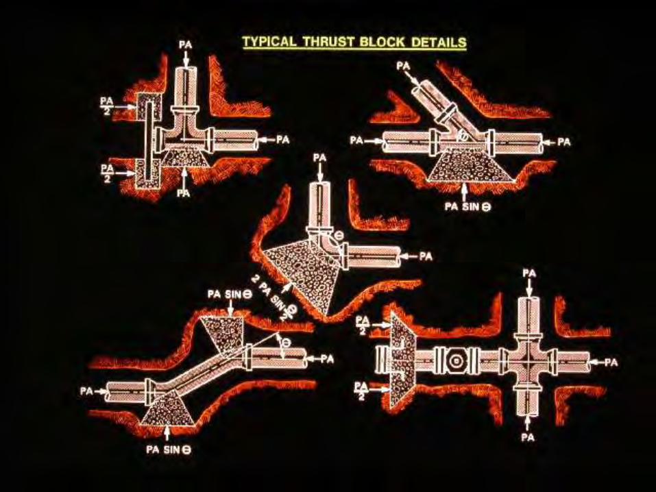

Gravity Thrust Block
Gravity Block Size (ft3) =Safety Factor • Thrust Force (lb)
Density of Block Material (lb/ft3)
Gravity Block

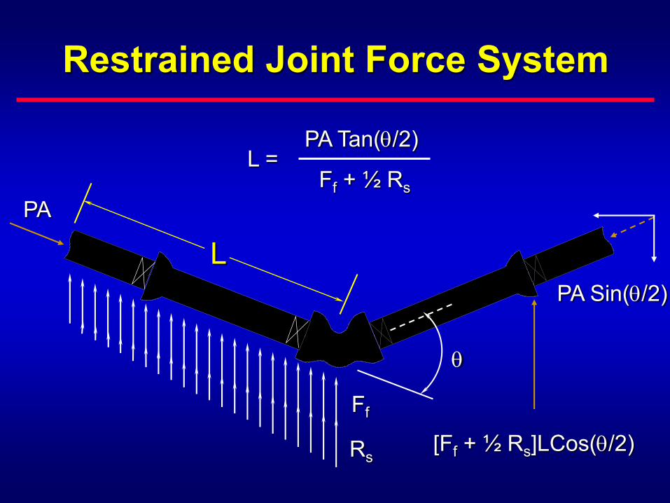
Restrained Joint Force System
PA
Ff
Rs
PA Sin(/2)
PA Tan(/2)
Ff + ½ Rs
L =
[Ff + ½ Rs]LCos(/2)
L


Restrained Joints
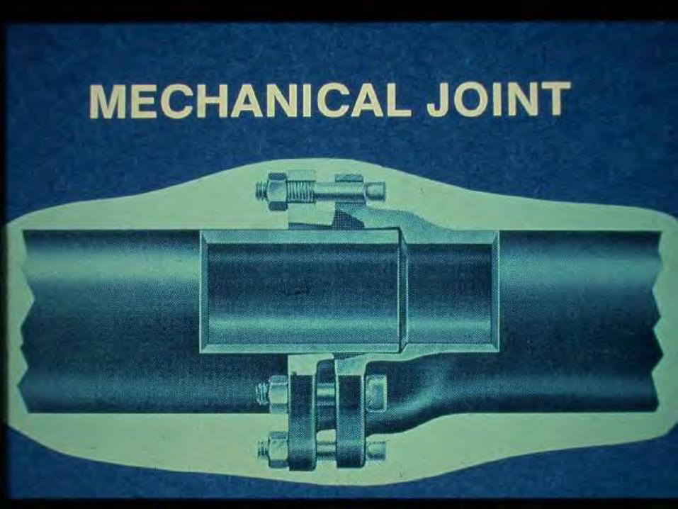

Mechanical Joint Retainer Glands
Set-ScrewMechanical JointRetainer Gland
Wedge-actionMechanical JointRetainer Gland

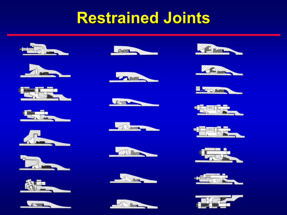
Restrained Joints
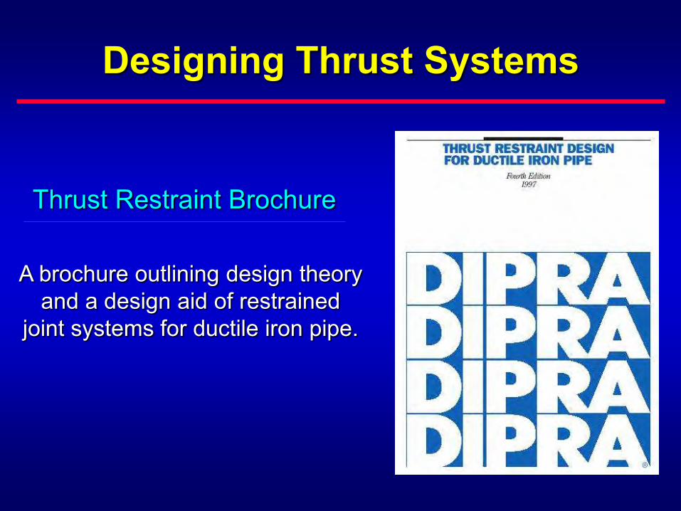
Designing Thrust Systems
Thrust Restraint Brochure
A brochure outlining design theoryand a design aid of restrained
joint systems for ductile iron pipe.
Restrained Joint Force System
PA
Ff
Rs
PA Sin(/2)
PA Tan(/2)
Ff + ½ Rs
L =
[Ff + ½ Rs]LCos(/2)
L

Restrained Length Dependant Upon
Pipe sizeType of fittingInternal pressureDepth of coverSoil characteristicsLaying conditions

Suggested Values for Soil Propertiesand Reduction Constant
Soil Designation Soil Description
(deg)f
Cs
(psf)fc
γ(deg)
K nA21.50 Laying
Condition2* 3 4 5
Clay 1Clay of medium to low plasticity, LL<50, <25% coarse particles
[CL & CL-ML]0 0 300
.50
.8090 .20 .40 .60 .85
Coh-gran Cohesive granular soils,> 50% coarse particles [GC & SC] 20
.40
.65200 .40 90 .40 .60 .85 1.0
Sand Silt Sand or gravel w/silt,> 50% coarse particles [GM & SM] 30
.50
.750 0 90 .40 .60 .85 1.0
Good Sand Clean sand, >95% coarse particles, [SW & SP] 36
.75
.800 0 100 .40 .60 .85 1.0
Consult Table 3 of thrust brochure for pertinent notes.
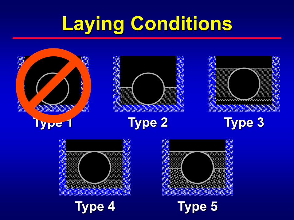
Laying Conditions
Type 1
Type 4
Type 2 Type 3
Type 5
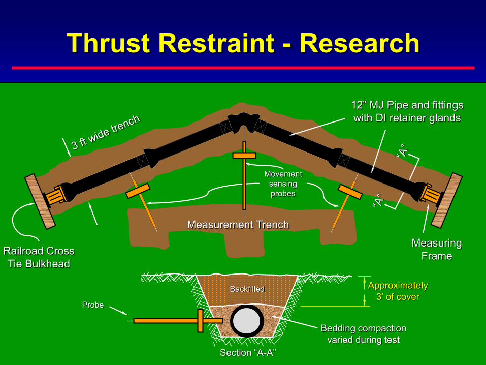
Thrust Restraint - Research
Measurement Trench
12” MJ Pipe and fittingswith DI retainer glands
Movementsensingprobes
Railroad CrossTie Bulkhead
MeasuringFrame
Probe
Backfilled Approximately3’ of cover
Bedding compactionvaried during test
Section “A-A”

Designing Thrust Systems
A computer program to aid inthe design of restrained jointsystems for ductile iron pipe.
Thrust Restraint Computer Program

Table B-5
Size(in)
Depth(ft)
A21.50 – Laying Conditions2 3 4 5
RestrainedLength (ft)
RestrainedLength (ft)
RestrainedLength (ft)
RestrainedLength (ft)
30 2.5 97 (112) 69 (79) 56 (62) 50 (55)
30 3.0 91 (105) 65 (74) 52 (58) 47 (51)
30 4.0 81 (93) 57 (65) 46 (51) 41 (45)
30 6.0 66 (76) 46 (52) 37 (41) 33 (36)
30 8.0 56 (64) 38 (44) 31 (34) 28 (30)
30 10.0 48 (56) 33 (38) 26 (30) 24 (26)
2 3 4 5f 0.40 0.65 0.65 0.65f c 0.40 0.40 0.40 0.40K n 0.40 0.60 0.80 1.00
A21.50 – Laying ConditionsSoil Type: Coh-granSoil Parameters
Cs
= 20 degrees= 200 psf= 90 pcf
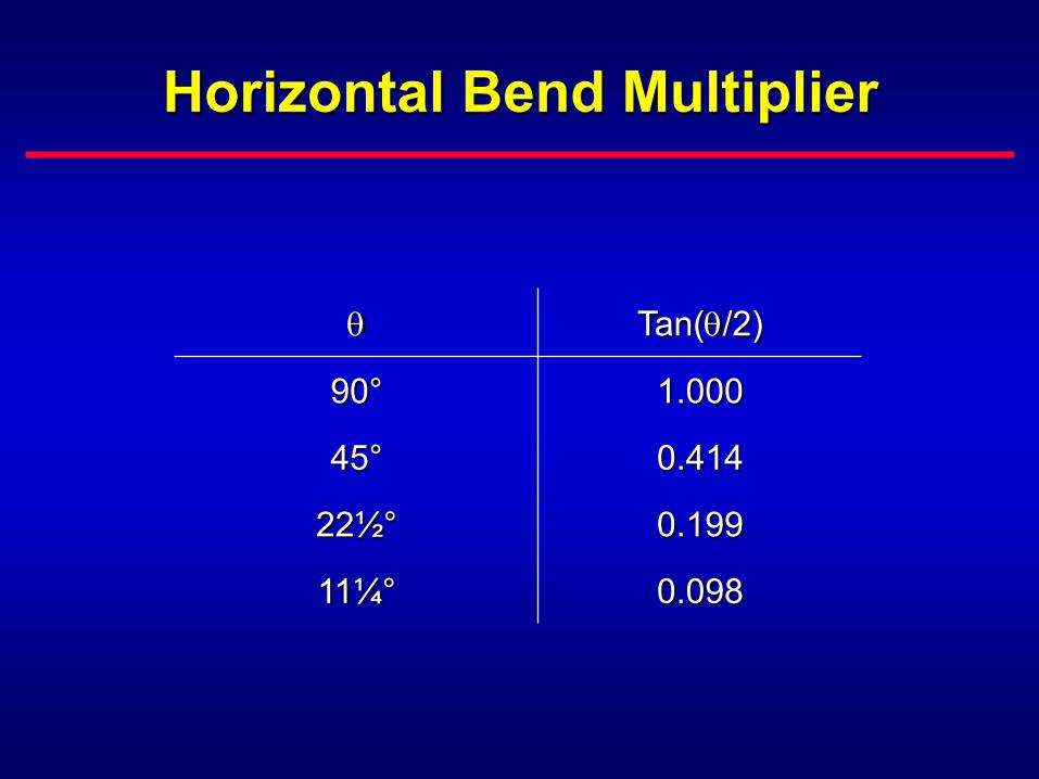
Horizontal Bend Multiplier
Tan(/2)
90° 1.000
45° 0.414
22½° 0.199
11¼° 0.098
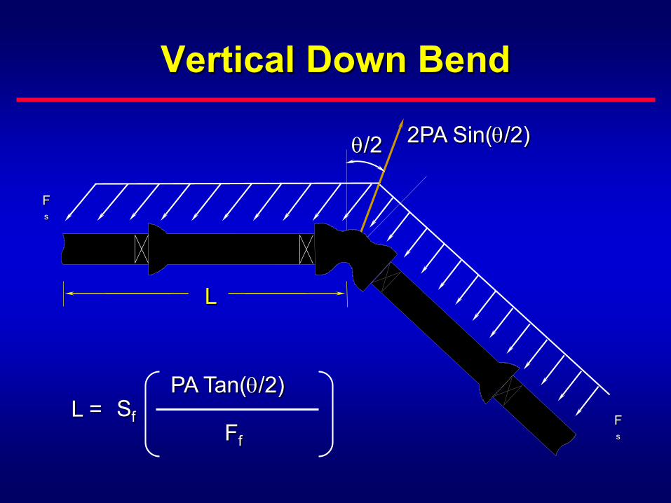
Vertical Down Bend
/2 2PA Sin(/2)
Fs
PA Tan(/2)
Ff
L = Sf
Fs
L

Lr
Tee
PAb -1/2 RsLr
(Ff )b
Lb = Sf
Lb
Lb(Ff)b
PAb

Extend Restrained Joints at:
CasingsBridge crossingsAboveground applicationsPoor soil conditionsClosely located fittings
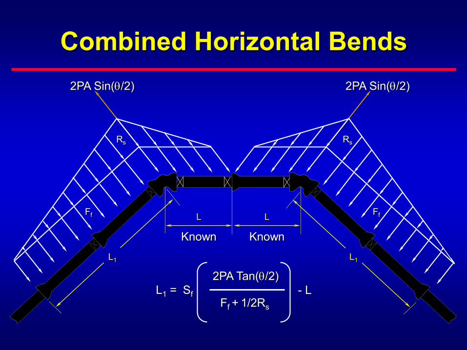
Combined Horizontal Bends
FfFf
RsRs
2PA Tan(/2)
Ff + 1/2Rs
L1 = Sf - L
L1 L1
LL
Known Known
2PA Sin(/2) 2PA Sin(/2)

Vertical Offset
Ff
Ff
L1 L
L2L
Rs
2PA Tan(/2)
Ff
L1 = Sf - L
2PA Tan(/2)
Ff + 1/2Rs
L2 = Sf - L
2PA Sin(/2)
2PA Sin(/2)

Combined Vertical Equal Angle Offsets
2PA Tan(/2)
Ff
L1 = Sf - L
L
FfFf
L1L1
L
LL


Thrust Restraint - Closures
L1L1
L2
L2
Closure
Closure
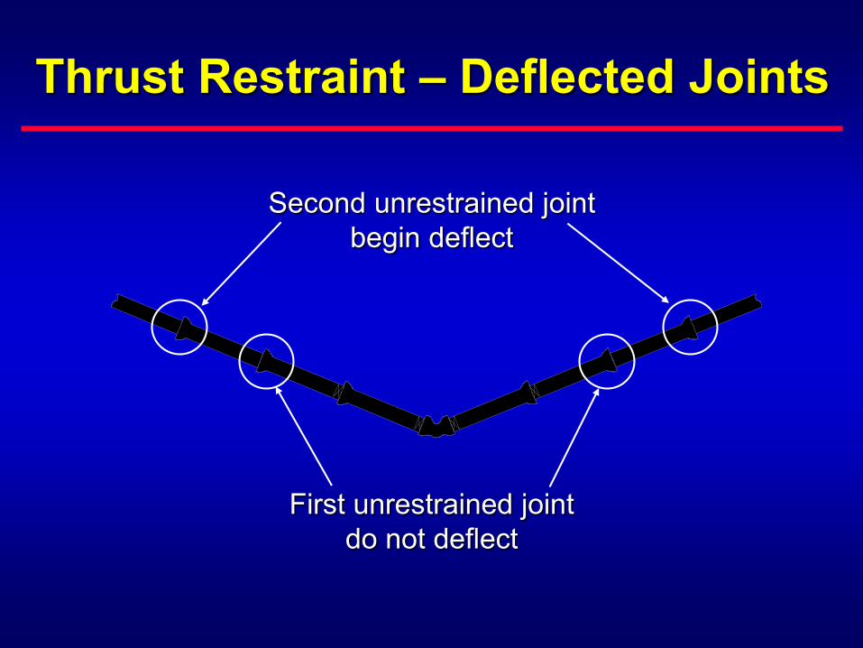
Thrust Restraint – Deflected Joints
First unrestrained jointdo not deflect
Second unrestrained jointbegin deflect

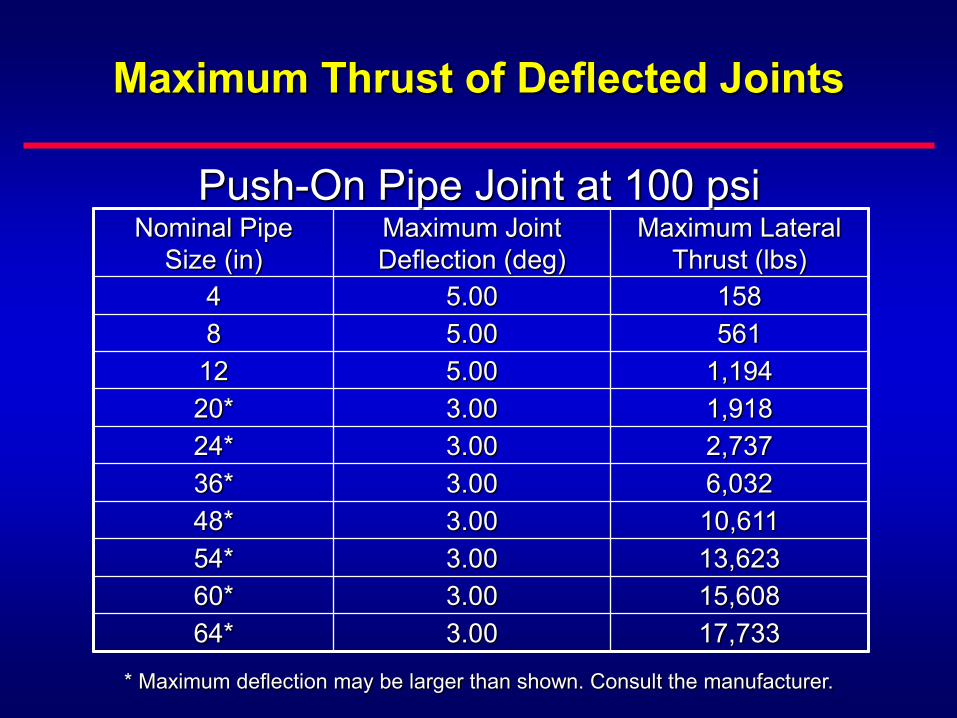
Maximum Thrust of Deflected Joints
Nominal PipeSize (in)
Maximum Joint Deflection (deg)
Maximum Lateral Thrust (lbs)
4 5.00 1588 5.00 561
12 5.00 1,19420* 3.00 1,91824* 3.00 2,73736* 3.00 6,03248* 3.00 10,61154* 3.00 13,62360* 3.00 15,60864* 3.00 17,733
Push-On Pipe Joint at 100 psi
* Maximum deflection may be larger than shown. Consult the manufacturer.
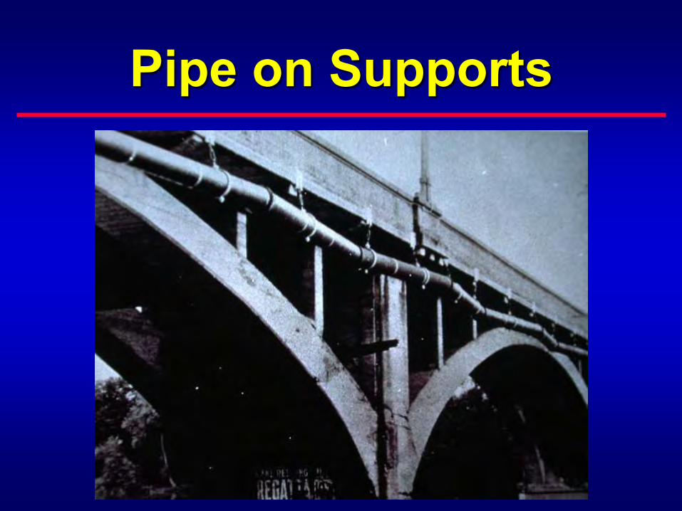
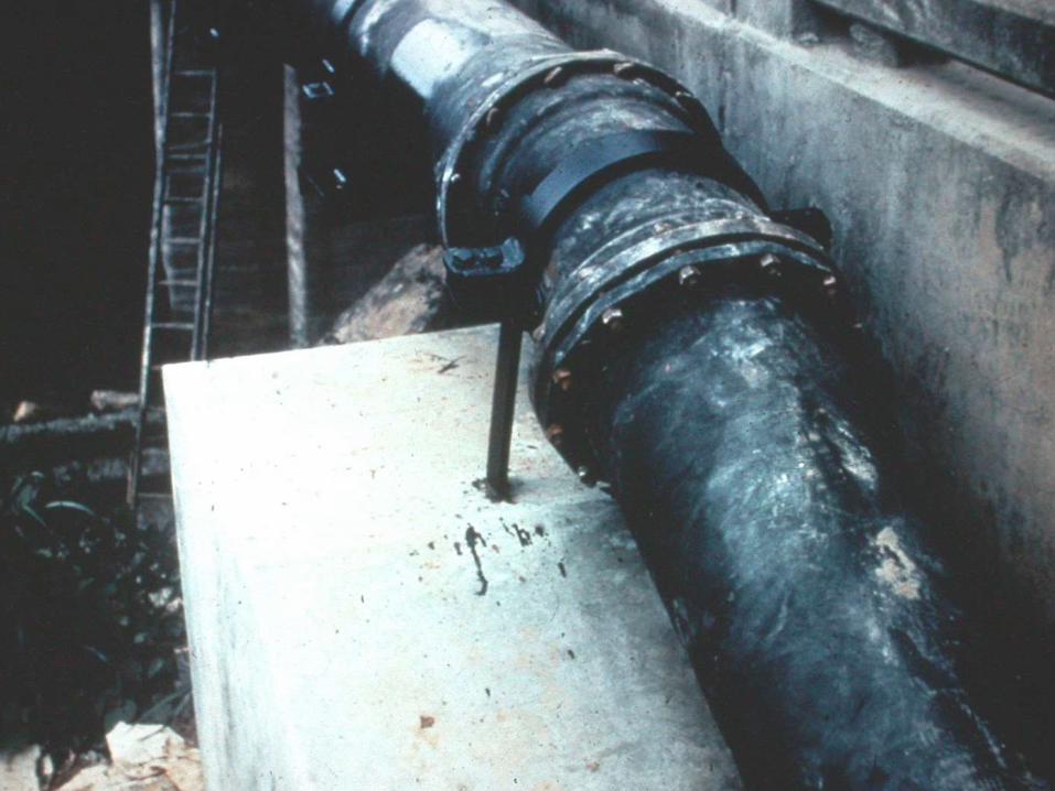
Pipe on Supports
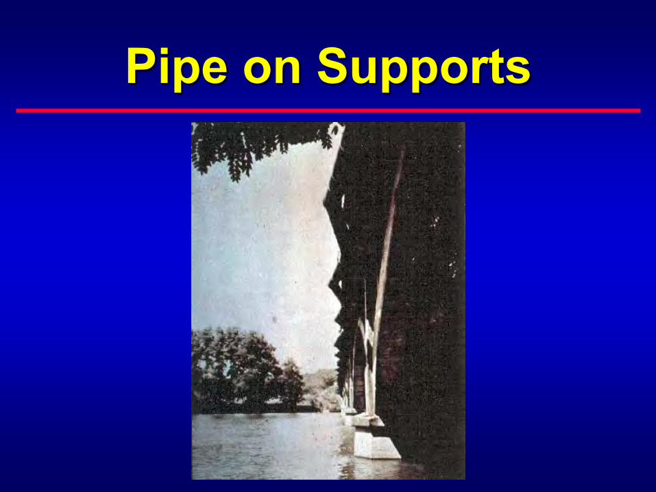
Pipe on Supports
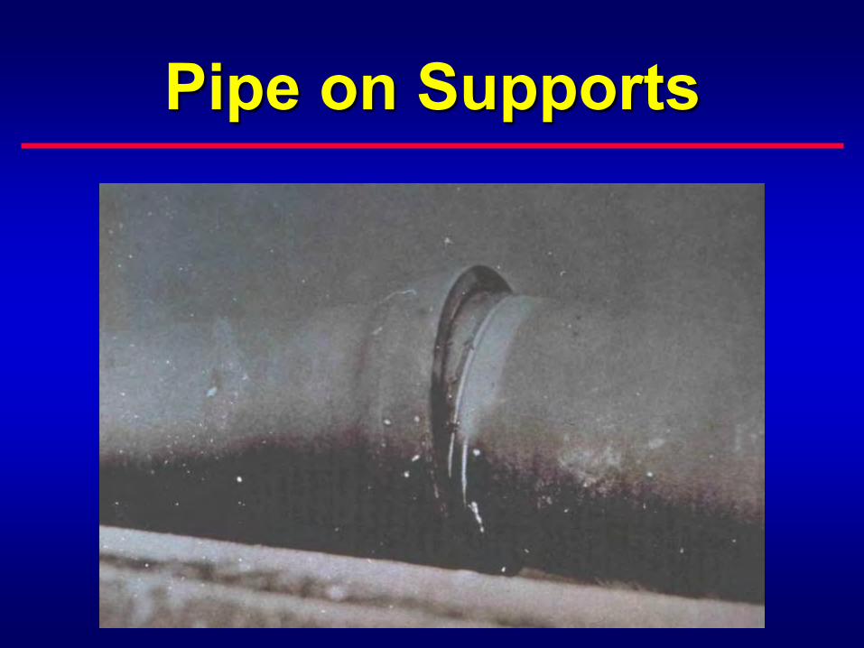
Pipe on Supports

Is Steel Strap Required?

Combined Horizontal Bends
FfFf
RsRs
2PA Tan(/2)
Ff + 1/2Rs
L1 = Sf - L
L1 L1
LL
Known Known
2PA Sin(/2) 2PA Sin(/2)
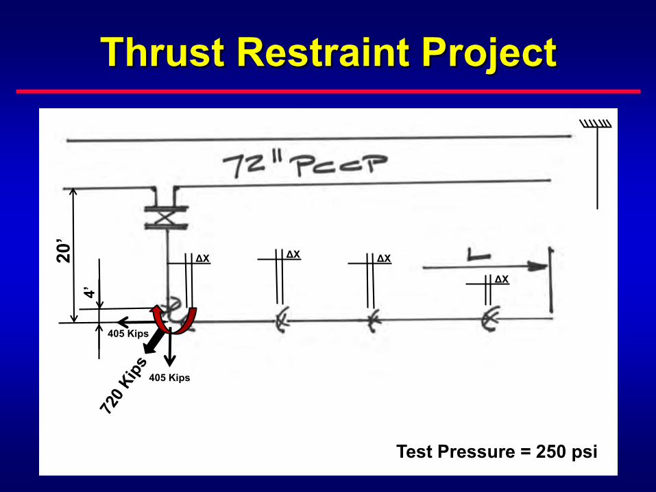
Thrust Restraint Project
Test Pressure = 250 psi
20’
4’
405 Kips
405 Kips
ΔX ΔXΔX
ΔX

Thrust Restraint Project
Test Pressure = 250 psi
20’
4’
405 Kips
405 Kips
ΔX ΔXΔX
ΔX

Thrust Restraint Project
Test Pressure = 250 psi
20’
4’
405 Kips
405 Kips
ΔX ΔXΔX
ΔX
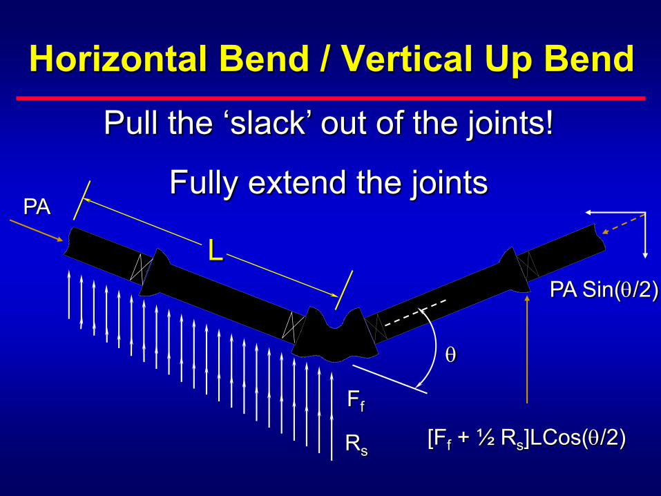
Horizontal Bend / Vertical Up Bend
PA
Ff
Rs
PA Sin(/2)
[Ff + ½ Rs]LCos(/2)
L
Pull the ‘slack’ out of the joints!
Fully extend the joints

Thrust Restraint

Components Requiring Thrust Restraint
BendsTeesDead endsHydrantsOffsetsReducers

Components Requiring Thrust Restraint
BendsTeesDead endsHydrantsOffsetsReducers
T = (P1 – P2) A

Horizontal Bend / Vertical Up Bend
PA
Ff
Rs
PA Sin(/2)
[Ff + ½ Rs]LCos(/2)
L
PA Tan(/2)
Ff + ½ Rs
L = Sf

TieRods


Calculating Number of Tie Rods
F = SA
N = Sf T(X or Y)
FWhere:
F = Force Developed per Rod (lbs.)
S = Tensile Strength of Rod Material (psi)
A = Cross Sectional Area of Rod (in.2)
N = Number of Rods Required
T(X or Y) = Thrust Force Component (lbs.)
Sf = Safety Factor (usually 1.5)

CombinedSystems


Installation


Resistivity: 2,520 ohm-cm
Chicopee, MA– 20 inch Cast Iron PipeInstalled: 1898 – Inspected: 2014
Member: Cast Iron Pipe Century Club

Resistivity: 2,520 ohm-cm
Chicopee, MA– 20 inch Cast Iron PipeInstalled: 1898 – Inspected: 2014
Member: Cast Iron Pipe Century Club

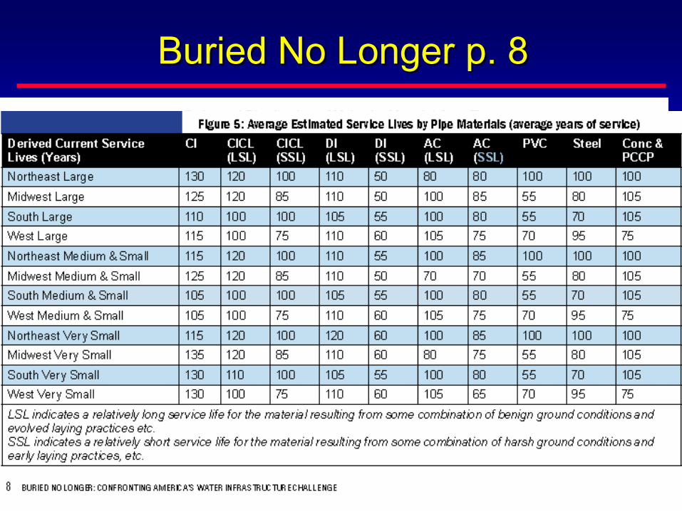
Buried No Longer p. 8
“this report…constitutes the most thorough and
comprehensive analysis ever undertaken of the
nation’s drinking water infrastructure renewal needs.”

Integrity isn’t Expensiveit’s
PRICELESS
Ductile Iron PipeThe Right Decision