Embed Size (px)
DESCRIPTION
-
Citation preview
C O M P R E H E N S I V E D E S I G N G U I D E
EqualizingThrust Bearings
2
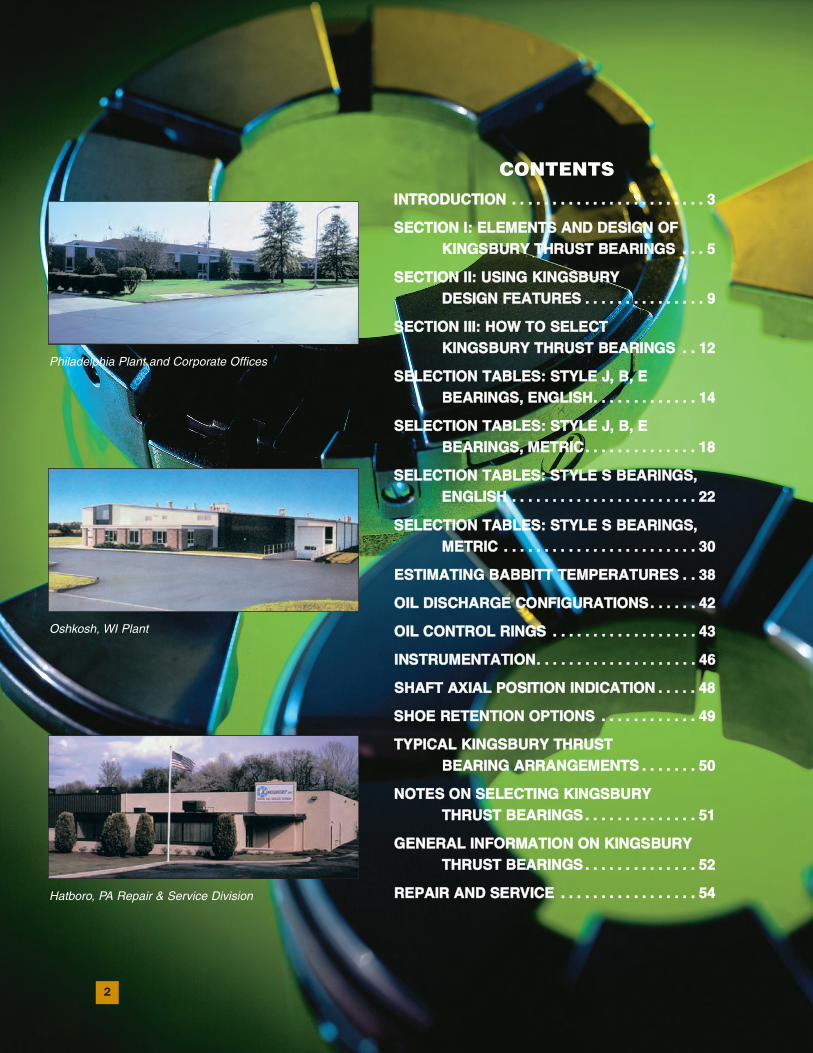
CONTENTSIINNTTRROODDUUCCTTIIOONN .. .. .. .. .. .. .. .. .. .. .. .. .. .. .. .. .. .. .. .. .. .. .. .. 33
SSEECCTTIIOONN II:: EELLEEMMEENNTTSS AANNDD DDEESSIIGGNN OOFFKKIINNGGSSBBUURRYY TTHHRRUUSSTT BBEEAARRIINNGGSS .. .. .. 55
SSEECCTTIIOONN IIII:: UUSSIINNGG KKIINNGGSSBBUURRYY DDEESSIIGGNN FFEEAATTUURREESS .. .. .. .. .. .. .. .. .. .. .. .. .. .. .. 99
SSEECCTTIIOONN IIIIII:: HHOOWW TTOO SSEELLEECCTT KKIINNGGSSBBUURRYY TTHHRRUUSSTT BBEEAARRIINNGGSS .. .. 1122
SSEELLEECCTTIIOONN TTAABBLLEESS:: SSTTYYLLEE JJ,, BB,, EEBBEEAARRIINNGGSS,, EENNGGLLIISSHH.. .. .. .. .. .. .. .. .. .. .. .. .. 1144
SSEELLEECCTTIIOONN TTAABBLLEESS:: SSTTYYLLEE JJ,, BB,, EEBBEEAARRIINNGGSS,, MMEETTRRIICC.. .. .. .. .. .. .. .. .. .. .. .. .. .. 1188
SSEELLEECCTTIIOONN TTAABBLLEESS:: SSTTYYLLEE SS BBEEAARRIINNGGSS,,EENNGGLLIISSHH .. .. .. .. .. .. .. .. .. .. .. .. .. .. .. .. .. .. .. .. .. .. .. 2222
SSEELLEECCTTIIOONN TTAABBLLEESS:: SSTTYYLLEE SS BBEEAARRIINNGGSS,,MMEETTRRIICC .. .. .. .. .. .. .. .. .. .. .. .. .. .. .. .. .. .. .. .. .. .. .. .. 3300
EESSTTIIMMAATTIINNGG BBAABBBBIITTTT TTEEMMPPEERRAATTUURREESS .. .. 3388
OOIILL DDIISSCCHHAARRGGEE CCOONNFFIIGGUURRAATTIIOONNSS.. .. .. .. .. .. 4422
OOIILL CCOONNTTRROOLL RRIINNGGSS .. .. .. .. .. .. .. .. .. .. .. .. .. .. .. .. .. .. 4433
IINNSSTTRRUUMMEENNTTAATTIIOONN.. .. .. .. .. .. .. .. .. .. .. .. .. .. .. .. .. .. .. .. 4466
SSHHAAFFTT AAXXIIAALL PPOOSSIITTIIOONN IINNDDIICCAATTIIOONN .. .. .. .. .. 4488
SSHHOOEE RREETTEENNTTIIOONN OOPPTTIIOONNSS .. .. .. .. .. .. .. .. .. .. .. .. 4499
TTYYPPIICCAALL KKIINNGGSSBBUURRYY TTHHRRUUSSTT BBEEAARRIINNGG AARRRRAANNGGEEMMEENNTTSS .. .. .. .. .. .. .. 5500
NNOOTTEESS OONN SSEELLEECCTTIINNGG KKIINNGGSSBBUURRYY TTHHRRUUSSTT BBEEAARRIINNGGSS .. .. .. .. .. .. .. .. .. .. .. .. .. .. 5511
GGEENNEERRAALL IINNFFOORRMMAATTIIOONN OONN KKIINNGGSSBBUURRYYTTHHRRUUSSTT BBEEAARRIINNGGSS .. .. .. .. .. .. .. .. .. .. .. .. .. .. 5522
RREEPPAAIIRR AANNDD SSEERRVVIICCEE .. .. .. .. .. .. .. .. .. .. .. .. .. .. .. .. .. 5544
Philadelphia Plant and Corporate Offices
Oshkosh, WI Plant
Hatboro, PA Repair & Service Division
3
INTRODUCTIONKingsbury thrust bearings are a product of many years of design refinement and
application experience. In this Design Guide we have condensed our years of experience
into guidelines and recommendations that will help you to apply Kingsbury thrust
bearings with confidence, whether you are an experienced designer or a novice faced
with your first bearing application.
The Guide contains three sections that will guide you to a proper thrust bearing
selection. Each section highlights special design considerations and offers suggestions
you may find valuable in you design efforts.
The first section presents information that will help you understand the fundamentals
of equalizing fluid film thrust bearings. Section II reviews the design features of our thrust
bearings and the accessories available for monitoring bearing performance. In Section III,
we have provided step-by-step guidelines for selecting the proper Kingsbury bearing for
your particular application. If you desire a better understanding of bearing technology and
its evolution, please request Kingsbury’s General Guide to the Principles, Operation and
Troubleshooting of Hydrodynamic Bearings.
While this guide concentrates on equalizing thrust bearings intended for use on
horizontal shafts, the same shoe and leveling plate components can be mounted in a
modified base ring suitable for vertical shaft applications. These shoe and leveling plate
sets can also be mounted in combination thrust and journal bearings.
In a Design Guide such as this one, it is impossible to include every style and type
of product that is available. For instance, we manufacture shoe type journal bearings
for use alone or in combination with our thrust bearings; we can provide bearings
larger than those shown in the following pages; and we can design special bearings
to fit particular application requirements. If you have a special bearing requirement
not covered in this catalog, please send your specifications to us and we will make the
appropriate bearing recommendations.
4
AN HISTORICAL NOTESince 1912, Kingsbury has enjoyed recognition as the leader in the design and manufac-
ture of equalizing fluid film thrust bearings. We owe our success to the inventive spirit,
diligence, and perseverance of our founder, Dr. Albert Kingsbury. In all of his roles, as
mechanical engineer, college professor, inventor and businessman, Dr. Kingsbury made
outstanding contributions to the bearing industry. His most notable achievement, the
pivoted shoe thrust bearing, has dramatically improved the performance of many
machines that operate at high speeds under heavy loads.
Dr. Kingsbury’s odyssey began in 1884, when he entered Ohio State University at
Columbus as a freshman, to study mechanical engineering. At the end of his sophomore
year, he left Ohio State to work as a draftsman and serviceman for a company that
manufactured wire drawing machines. A year later, in the fall of 1887, he enrolled in
Sibley College, Cornell University, as a junior in mechanical engineering, and continued
there until graduation in 1889.
It was during his junior year at Cornell that he first recognized the need for improved
thrust bearings. After graduation, he continued his study of thrust bearings while a
professor of mechanical engineering at New Hampshire College of Agriculture and the
Mechanic Arts (now the University of New Hampshire). Using Osborne Reynold’s theory
of lubrication, Dr. Kingsbury built the first centrally pivoted thrust bearing and proved
it operational in 1898. Several years later, while employed as a practicing engineer,
Dr. Kingsbury found his first opportunity to apply his unique bearing design. Finally,
in 1910, the U.S. government awarded him a patent for his thrust bearing.
In 1912, Dr. Kingsbury entered into business for himself, ultimately founding the
Kingsbury Machine Works in Philadelphia, to manufacture the now famous Kingsbury
thrust bearing. Since those early days, we have grown steadily, developed new bearing
designs, improved bearing performance, and adapted our designs and manufacturing
techniques to meet the requirements of successively more demanding applications.
Our corporate offices, engineering staff, large and medium size manufacturing operations,
and our research and development laboratory are still located in Philadelphia, but today we
also operate a second plant in Oshkosh, WI devoted to the manufacture of small and medium
size precision bearings. In addition, Kingsbury maintains a facility in Hatboro, PA, dedicated to
the repair and service of all types and brands of babbitted bearings (see page 54).
As he built his company, Dr. Kingsbury imbued it with his sense of diligence, attention
to detail, pride in quality, and devotion to customer service—traits that have remained
hallmarks of Kingsbury, Inc. through the years.
5
SECTION I
Beginning with a fundamental review of theKingsbury thrust bearing, this section listsbasic bearing elements and how they work, as well as design options and accessories.
How Kingsbury’s Thrust Bearing Works A thrust bearing transmits axial shaft loads intothe foundation or machine support of rotatingapparatus. Our equalizing thrust bearing actually transmits the load through a self-renewing film of oil during operation and aunique force-balancing action distributes theload across the shoes. Working surfaces toucheach other only during start-up and shut-down.Otherwise, these surfaces are separated by thefluid film, so surface wear is minimal, andbearing life dramatically lengthened.
The Kingsbury thrust bearing offers manyoperating advantages, including:
• Excellent shock absorbing capacity
• Superior damping characteristics
• Life span equal to that of the machine
• Versatility in application
• Performance monitoring capability
Basic ElementsHere is a quick review of the basic elementsin a Kingsbury equalizing fluid film thrustbearing:
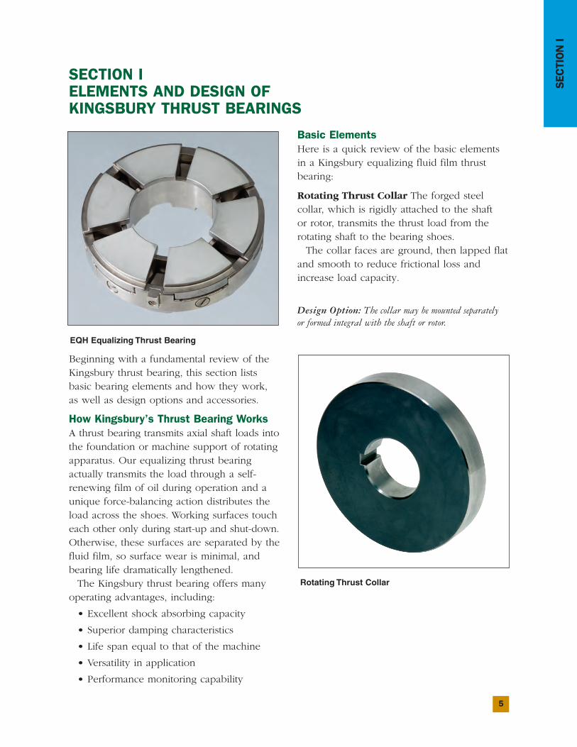
Rotating Thrust Collar The forged steel collar, which is rigidly attached to the shaft or rotor, transmits the thrust load from therotating shaft to the bearing shoes.
The collar faces are ground, then lapped flatand smooth to reduce frictional loss andincrease load capacity.
Design Option: The collar may be mounted separately or formed integral with the shaft or rotor.
SECTION I ELEMENTS AND DESIGN OF KINGSBURY THRUST BEARINGS
Rotating Thrust Collar
EQH Equalizing Thrust Bearing
6
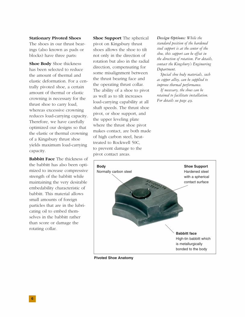
Stationary Pivoted ShoesThe shoes in our thrust bear-ings (also known as pads orblocks) have three parts:
Shoe Body Shoe thicknesshas been selected to reducethe amount of thermal andelastic deformation. For a cen-trally pivoted shoe, a certainamount of thermal or elasticcrowning is necessary for thethrust shoe to carry load,whereas excessive crowningreduces load-carrying capacity.Therefore, we have carefullyoptimized our designs so thatthe elastic or thermal crowningof a Kingsbury thrust shoeyields maximum load-carryingcapacity.
Babbitt Face The thickness ofthe babbitt has also been opti-mized to increase compressivestrength of the babbitt whilemaintaining the very desirableembedability characteristic ofbabbitt. This material allowssmall amounts of foreign particles that are in the lubri-cating oil to embed them-selves in the babbitt ratherthan score or damage therotating collar.
Shoe Support The sphericalpivot on Kingsbury thrustshoes allows the shoe to tiltnot only in the direction ofrotation but also in the radialdirection, compensating forsome misalignment betweenthe thrust bearing face andthe operating thrust collar.The ability of a shoe to pivotas well as to tilt increasesload-carrying capability at allshaft speeds. The thrust shoepivot, or shoe support, andthe upper leveling platewhere the thrust shoe pivotmakes contact, are both made of high carbon steel, heat-treated to Rockwell 50C, to prevent damage to thepivot contact areas.
Design Options: While the standard position of the hardened steel support is at the center of the shoe, this support can be offset in the direction of rotation. For details,contact the Kingsbury’s EngineeringDepartment.
Special shoe body materials, such as copper alloy, can be supplied toimprove thermal performance.
If necessary, the shoes can beretained to facilitate installation. For details see page 49.
Body Normally carbon steel
Shoe Support Hardened steel with a spherical contact surface
Pivoted Shoe Anatomy
Babbitt face High-tin babbitt which is metallurgically bonded to the body
7
SECTION I
Stationary Base Ring andLeveling Plate AssemblyMade of cast, plate, or forgedsteel, the base ring holds theshoes and leveling plates intheir operating positions. Anoil inlet annulus, at the backof the base ring, distributes oil to radial slots in the ring’sback face.
This assembly uses theequalizing principle devel-oped by Dr. Albert Kingsburyto distribute the load equallyover the bearing shoes andtransmit the load to the bearing housing.
Design Options: Bearing load canbe measured by inserting strain gaugeload cells in the upper leveling platesor thrust shoes. This feature can beretrofitted to installations in the field.For further information, see page 47.
The base ring may be drilled andtapped for mounting shim packs or filter plates, if necessary. ContactKingsbury for full details.
Leveling Plates The equaliz-ing feature of the Kingsburythrust bearing allows eachshoe to carry an equalamount of the total thrustload. The leveling plate fea-ture reduces the chance of
one shoe being more highlyloaded than another shoe.The leveling plates, combinedwith the spherical shoe support, also ensure that the thrust bearing facebecomes perfectly alignedwith the rotating thrust collar.
Number of Thrust ShoesThe standard Kingsbury thrustbearing usually has six oreight pivoted thrust shoesheld in the base ring carrier.In the base ring there areupper leveling plates andlower leveling plates to
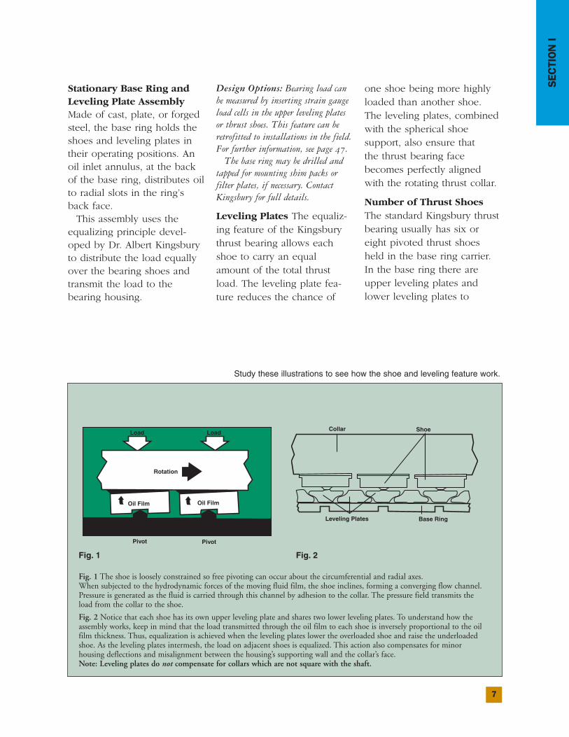
Fig. 1 The shoe is loosely constrained so free pivoting can occur about the circumferential and radial axes.When subjected to the hydrodynamic forces of the moving fluid film, the shoe inclines, forming a converging flow channel.Pressure is generated as the fluid is carried through this channel by adhesion to the collar. The pressure field transmits the load from the collar to the shoe.
Fig. 2 Notice that each shoe has its own upper leveling plate and shares two lower leveling plates. To understand how theassembly works, keep in mind that the load transmitted through the oil film to each shoe is inversely proportional to the oilfilm thickness. Thus, equalization is achieved when the leveling plates lower the overloaded shoe and raise the underloadedshoe. As the leveling plates intermesh, the load on adjacent shoes is equalized. This action also compensates for minor housing deflections and misalignment between the housing’s supporting wall and the collar’s face. Note: Leveling plates do not compensate for collars which are not square with the shaft.
Study these illustrations to see how the shoe and leveling feature work.
Fig. 1 Fig. 2
8
equalize the thrust load. Whenthe number of thrust shoesincreases beyond eight shoes,the alignment and equalizingefficiency of the bearing isdiminished and peak shoetemperatures could increase.
Design FeaturesThe thrust bearings in this catalog have been designed to be used with many types ofmachines or applications. Thethrust shaft can rotate clock-wise or counterclockwise, orbidirectionally, if necessary.These bearings can be usedwith almost any type of oil, and, due to the equalizing
capability of the bearings, onlyreasonable care has to betaken in assembly to assurethat the bearings are alignedproperly. We manufacturemany of these bearings in sufficient quantities to provideeconomical advantages to theuser, and we stock them atour Philadelphia, PA andOshkosh, WI plants to facilitate prompt delivery.
Thrust bearings that lackpivoted thrust shoes and theequalizing feature of levelingplates cannot carry the sameloads as Kingsbury bearingsthat incorporate these design
advantages. This is becauseproper alignment of the bearing and housing relativeto the thrust collar is difficult,and because accumulatedmanufacturing tolerances can-not permit the fine precisionnecessary to accommodatehigher loads.
Kingsbury bearings, on the other hand, have beendesigned so that they offernot only maximum loadcapacity for the lifetime of themachine in which they’reinstalled, but also a series ofrefinements that add versatilityto their application.
9
SECTION II
Since 1912, we have gainedunequaled experience indesigning and manufacturingthrust bearings. This sectiondetails design features whichwe developed to improveyour machine’s performance.Please see discussion startingon page 42 for such items asoil control rings, strain gaugeload cells, and retained thrustshoes. That section explainshow these features work, andwhen you should use them.
LubricationFor Kingsbury thrust bearingsto operate safely and efficiently,continuous self-renewing oilfilms must be present betweenthe shoes and collar.
The oil supplied to the bearing should be cooled
and filtered, so that the average particle size is lessthan the bearing’s minimumfilm thickness. The typical oil flow path is shown below.
End PlayTo understand end play, or axial clearance, picture adouble thrust bearing (one on each side of the collar).End play is the distance thethrust collar can be movedbetween the bearings duringinstallation while applyingload to either bearing.
Note: End play isn’t an exact dimension. The shaft’smaximum end play is limitedto the smallest clearancebetween the stationary androtating machine elements,while the shaft’s minimum
end play must be sufficient
to prevent excessive power
loss in the unloaded thrust
bearing.
Any time a double thrust
bearing is installed, end play
must be provided to allow
for an oil film to form in
each bearing, and thermal
expansion of the bearing
elements.
Design Option: Normal thrustbearing overall height tolerances areabout ±0.04" (1.0 mm). To obtainsuitable end play, filler plates,machined to adjust for the tolerancesof the thrust bearing and bearinghousing, should be installed. If it isn’tpractical to use filler pieces in thebearing assembly, thrust bearings canbe provided with height tolerances of±0.005" (0.13mm) on special order.
SECTION II USING KINGSBURY DESIGN FEATURES
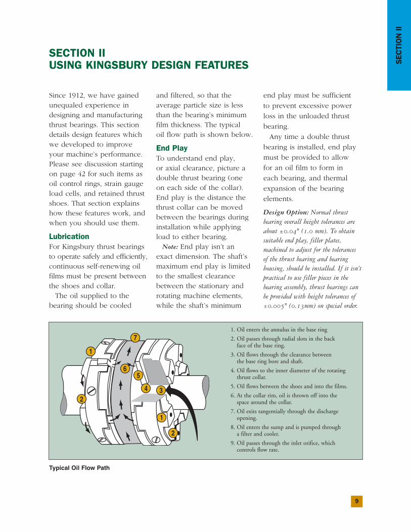
Typical Oil Flow Path
1. Oil enters the annulus in the base ring
2. Oil passes through radial slots in the back face of the base ring.
3. Oil flows through the clearance between the base ring bore and shaft.
4. Oil flows to the inner diameter of the rotating thrust collar.
5. Oil flows between the shoes and into the films.
6. At the collar rim, oil is thrown off into the space around the collar.
7. Oil exits tangentially through the discharge opening.
8. Oil enters the sump and is pumped through a filter and cooler.
9. Oil passes through the inlet orifice, which controls flow rate.
10
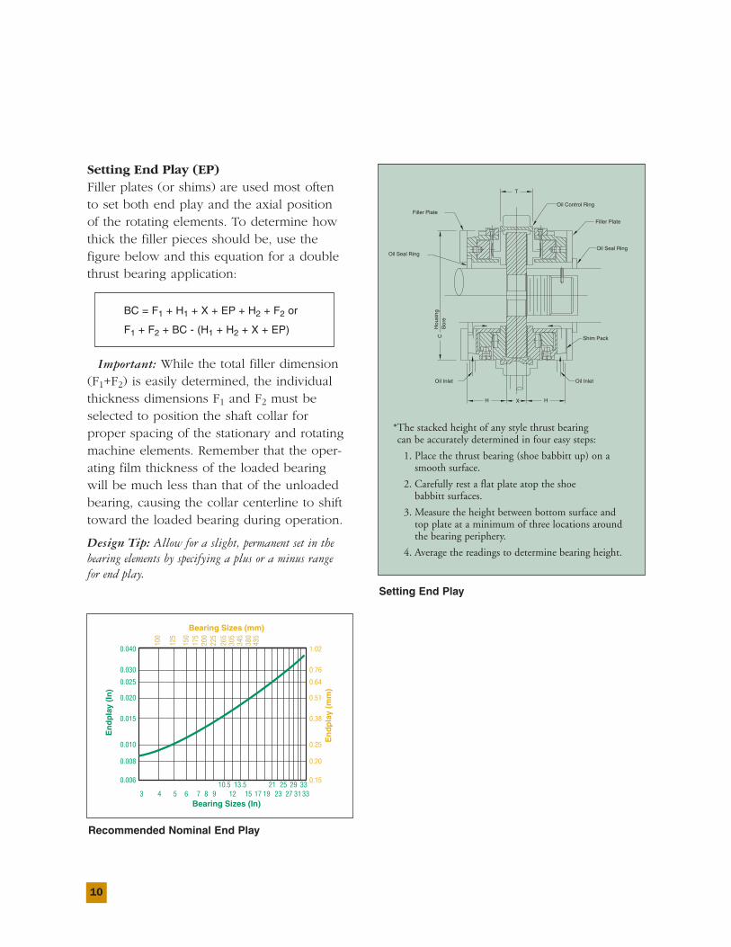
Setting End Play (EP)Filler plates (or shims) are used most often to set both end play and the axial position of the rotating elements. To determine howthick the filler pieces should be, use the figure below and this equation for a doublethrust bearing application:
BC = F1 + H1 + X + EP + H2 + F2 or
F1 + F2 + BC - (H1 + H2 + X + EP)
Important: While the total filler dimension(F1+F2) is easily determined, the individualthickness dimensions F1 and F2 must be selected to position the shaft collar for proper spacing of the stationary and rotatingmachine elements. Remember that the oper-ating film thickness of the loaded bearingwill be much less than that of the unloadedbearing, causing the collar centerline to shifttoward the loaded bearing during operation.
Design Tip: Allow for a slight, permanent set in thebearing elements by specifying a plus or a minus range for end play.
T
CH
ousi
ngB
ore
HH X
Oil Inlet
Shim Pack
Oil Inlet
Oil Control Ring
Filler Plate
Oil Seal Ring
Filler Plate
Oil Seal Ring
Setting End Play
*The stacked height of any style thrust bearing can be accurately determined in four easy steps:
1. Place the thrust bearing (shoe babbitt up) on asmooth surface.
2. Carefully rest a flat plate atop the shoe babbitt surfaces.
3. Measure the height between bottom surface andtop plate at a minimum of three locations aroundthe bearing periphery.
4. Average the readings to determine bearing height.
Recommended Nominal End Play
Bearing Sizes (In)
Bearing Sizes (mm)
En
dp
lay
(In
)
En
dp
lay
(mm
)
0.040
0.030
0.025
0.020
0.015
0.010
0.008
0.006
3 4 5 6 7 8 9 12 15 17 19 23 27 31 3310.5 13.5 21 25 29 33
1.02
100
125
150
175
200
225
265
305
345
380
435
0.76
0.64
0.51
0.38
0.25
0.20
0.15
11
SECTION II
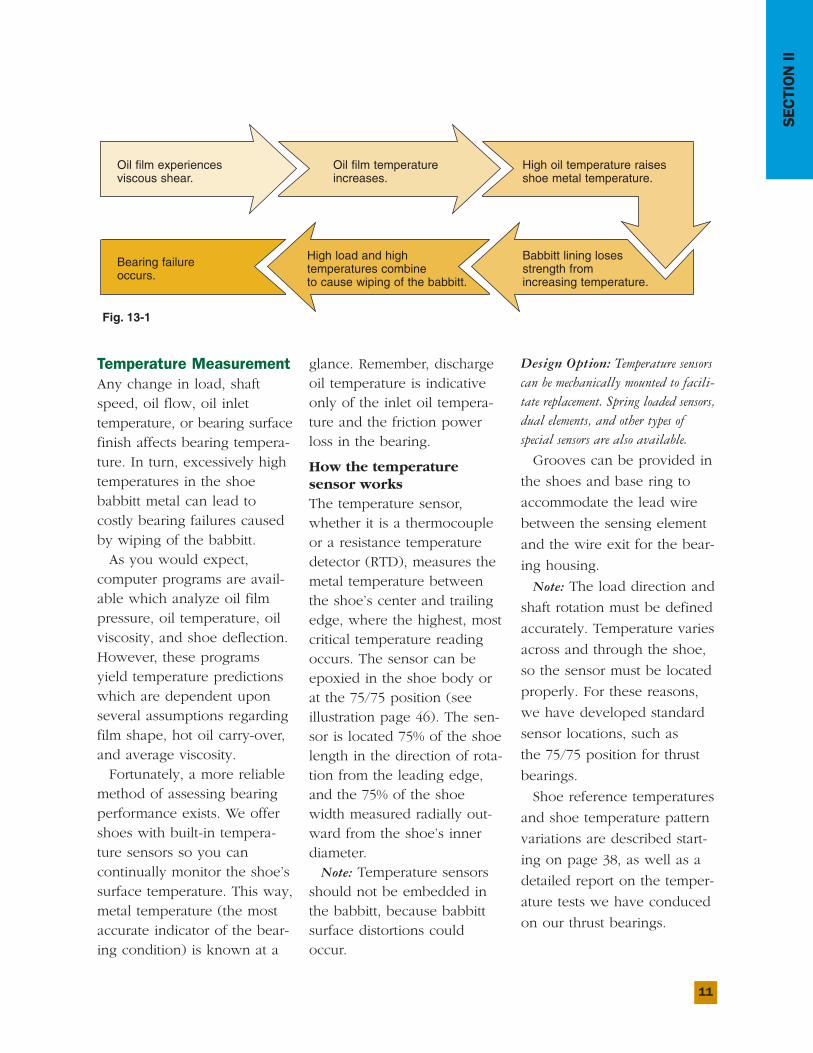
Temperature MeasurementAny change in load, shaftspeed, oil flow, oil inlet temperature, or bearing surfacefinish affects bearing tempera-ture. In turn, excessively hightemperatures in the shoe babbitt metal can lead to costly bearing failures causedby wiping of the babbitt.
As you would expect, computer programs are avail-able which analyze oil filmpressure, oil temperature, oilviscosity, and shoe deflection.However, these programsyield temperature predictionswhich are dependent uponseveral assumptions regardingfilm shape, hot oil carry-over,and average viscosity.
Fortunately, a more reliablemethod of assessing bearingperformance exists. We offershoes with built-in tempera-ture sensors so you can continually monitor the shoe’ssurface temperature. This way,metal temperature (the mostaccurate indicator of the bear-ing condition) is known at a
glance. Remember, dischargeoil temperature is indicativeonly of the inlet oil tempera-ture and the friction powerloss in the bearing.
How the temperature sensor worksThe temperature sensor,whether it is a thermocoupleor a resistance temperaturedetector (RTD), measures themetal temperature betweenthe shoe’s center and trailingedge, where the highest, mostcritical temperature readingoccurs. The sensor can beepoxied in the shoe body orat the 75/75 position (seeillustration page 46). The sen-sor is located 75% of the shoelength in the direction of rota-tion from the leading edge,and the 75% of the shoewidth measured radially out-ward from the shoe’s innerdiameter.
Note: Temperature sensorsshould not be embedded inthe babbitt, because babbittsurface distortions couldoccur.
Design Option: Temperature sensorscan be mechanically mounted to facili-tate replacement. Spring loaded sensors,dual elements, and other types of special sensors are also available.
Grooves can be provided in
the shoes and base ring to
accommodate the lead wire
between the sensing element
and the wire exit for the bear-
ing housing.
Note: The load direction and
shaft rotation must be defined
accurately. Temperature varies
across and through the shoe,
so the sensor must be located
properly. For these reasons,
we have developed standard
sensor locations, such as
the 75/75 position for thrust
bearings.
Shoe reference temperatures
and shoe temperature pattern
variations are described start-
ing on page 38, as well as a
detailed report on the temper-
ature tests we have conduced
on our thrust bearings.
Fig. 13-1
Oil film experiencesviscous shear.
Oil film temperatureincreases.
High oil temperature raisesshoe metal temperature.
Babbitt lining losesstrength from increasing temperature.
High load and high temperatures combine to cause wiping of the babbitt.
Bearing failure occurs.
12
Separable CollarsEach of the above bearingstyles can be furnished withseparable collars. Standardcollar bores and keywaysizes are shown in thedimension tables, but specialbores and keyway sizes canbe furnished upon request.We recommend that collarshave a close sliding fit onthe shaft, 0.001" – 0.003"(0.03 – 0.08mm).
SECTION III HOW TO SELECT KINGSBURY THRUST BEARINGS
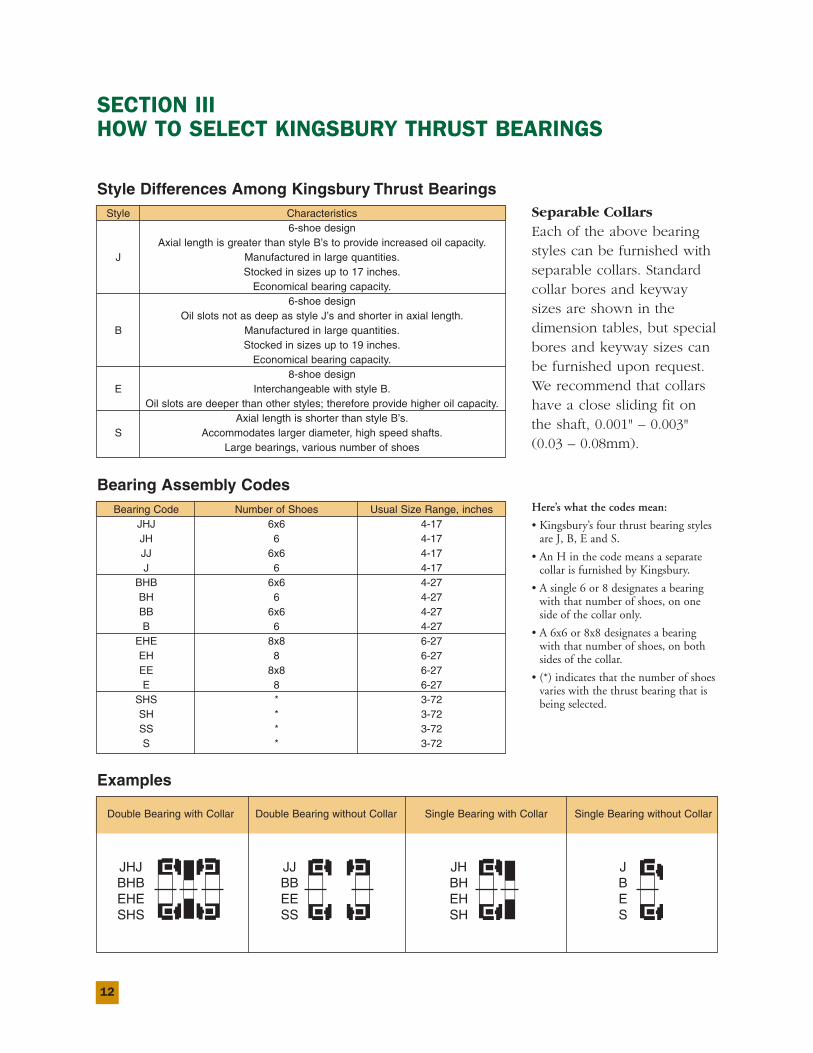
Style Differences Among Kingsbury Thrust BearingsStyle Characteristics
6-shoe designAxial length is greater than style B’s to provide increased oil capacity.
J Manufactured in large quantities.Stocked in sizes up to 17 inches.
Economical bearing capacity.6-shoe design
Oil slots not as deep as style J’s and shorter in axial length.B Manufactured in large quantities.
Stocked in sizes up to 19 inches.Economical bearing capacity.
8-shoe designE Interchangeable with style B.
Oil slots are deeper than other styles; therefore provide higher oil capacity.Axial length is shorter than style B’s.
S Accommodates larger diameter, high speed shafts.Large bearings, various number of shoes
Bearing Assembly CodesBearing Code Number of Shoes Usual Size Range, inches
JHJ 6x6 4-17JH 6 4-17JJ 6x6 4-17J 6 4-17
BHB 6x6 4-27BH 6 4-27BB 6x6 4-27B 6 4-27
EHE 8x8 6-27EH 8 6-27EE 8x8 6-27E 8 6-27
SHS * 3-72SH * 3-72SS * 3-72S * 3-72
Examples
Double Bearing with Collar Double Bearing without Collar Single Bearing with Collar Single Bearing without Collar
Here’s what the codes mean:
• Kingsbury’s four thrust bearing stylesare J, B, E and S.
• An H in the code means a separatecollar is furnished by Kingsbury.
• A single 6 or 8 designates a bearingwith that number of shoes, on oneside of the collar only.
• A 6x6 or 8x8 designates a bearingwith that number of shoes, on bothsides of the collar.
• (*) indicates that the number of shoesvaries with the thrust bearing that isbeing selected.
13
SECTION III
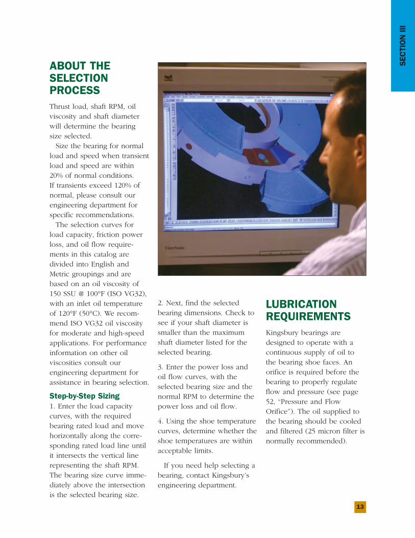
ABOUT THESELECTIONPROCESSThrust load, shaft RPM, oilviscosity and shaft diameterwill determine the bearingsize selected.
Size the bearing for normalload and speed when transientload and speed are within20% of normal conditions. If transients exceed 120% ofnormal, please consult ourengineering department forspecific recommendations.
The selection curves forload capacity, friction powerloss, and oil flow require-ments in this catalog aredivided into English andMetric groupings and arebased on an oil viscosity of150 SSU @ 100°F (ISO VG32),with an inlet oil temperatureof 120°F (50°C). We recom-mend ISO VG32 oil viscosityfor moderate and high-speedapplications. For performanceinformation on other oil viscosities consult our engineering department for assistance in bearing selection.
Step-by-Step Sizing1. Enter the load capacitycurves, with the requiredbearing rated load and movehorizontally along the corre-sponding rated load line untilit intersects the vertical linerepresenting the shaft RPM.The bearing size curve imme-diately above the intersectionis the selected bearing size.
2. Next, find the selectedbearing dimensions. Check tosee if your shaft diameter issmaller than the maximumshaft diameter listed for theselected bearing.
3. Enter the power loss andoil flow curves, with theselected bearing size and thenormal RPM to determine thepower loss and oil flow.
4. Using the shoe temperaturecurves, determine whether theshoe temperatures are withinacceptable limits.
If you need help selecting abearing, contact Kingsbury’sengineering department.
LUBRICATIONREQUIREMENTSKingsbury bearings aredesigned to operate with acontinuous supply of oil tothe bearing shoe faces. Anorifice is required before thebearing to properly regulateflow and pressure (see page52, “Pressure and FlowOrifice”). The oil supplied tothe bearing should be cooledand filtered (25 micron filter isnormally recommended).
14
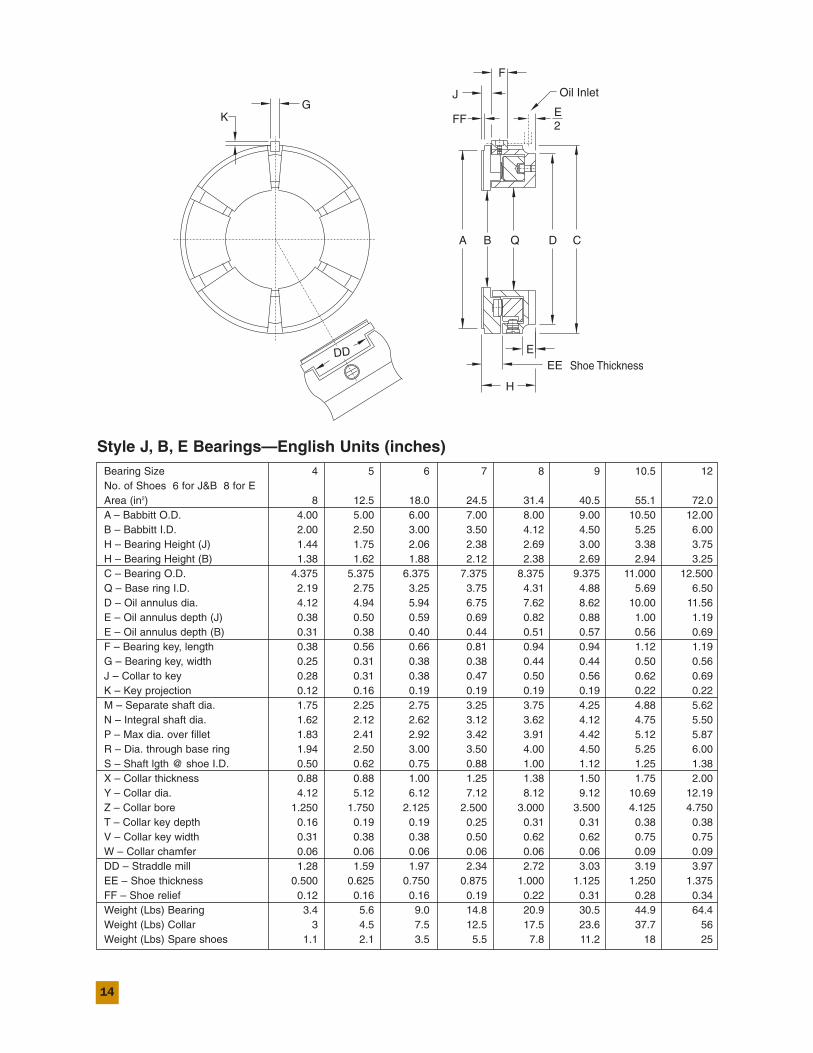
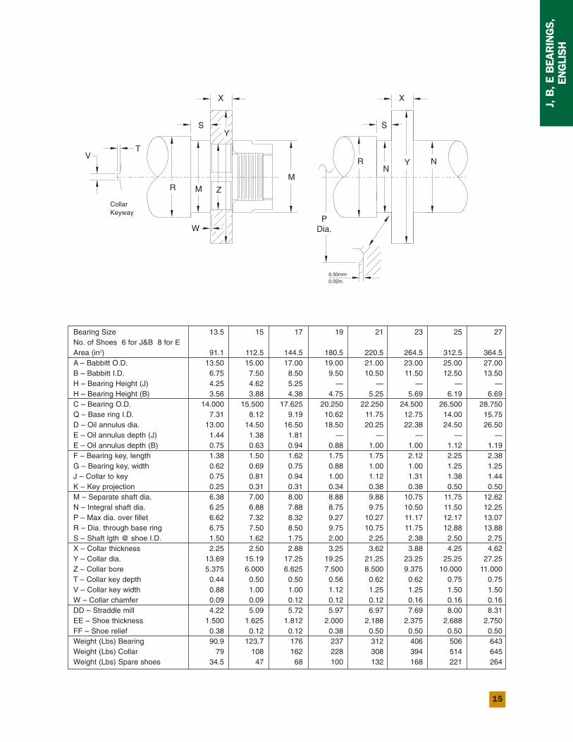
Style J, B, E Bearings—English Units (inches)Bearing Size 4 5 6 7 8 9 10.5 12No. of Shoes 6 for J&B 8 for EArea (in2) 8 12.5 18.0 24.5 31.4 40.5 55.1 72.0A – Babbitt O.D. 4.00 5.00 6.00 7.00 8.00 9.00 10.50 12.00B – Babbitt I.D. 2.00 2.50 3.00 3.50 4.12 4.50 5.25 6.00H – Bearing Height (J) 1.44 1.75 2.06 2.38 2.69 3.00 3.38 3.75H – Bearing Height (B) 1.38 1.62 1.88 2.12 2.38 2.69 2.94 3.25C – Bearing O.D. 4.375 5.375 6.375 7.375 8.375 9.375 11.000 12.500Q – Base ring I.D. 2.19 2.75 3.25 3.75 4.31 4.88 5.69 6.50D – Oil annulus dia. 4.12 4.94 5.94 6.75 7.62 8.62 10.00 11.56E – Oil annulus depth (J) 0.38 0.50 0.59 0.69 0.82 0.88 1.00 1.19E – Oil annulus depth (B) 0.31 0.38 0.40 0.44 0.51 0.57 0.56 0.69F – Bearing key, length 0.38 0.56 0.66 0.81 0.94 0.94 1.12 1.19G – Bearing key, width 0.25 0.31 0.38 0.38 0.44 0.44 0.50 0.56J – Collar to key 0.28 0.31 0.38 0.47 0.50 0.56 0.62 0.69K – Key projection 0.12 0.16 0.19 0.19 0.19 0.19 0.22 0.22M – Separate shaft dia. 1.75 2.25 2.75 3.25 3.75 4.25 4.88 5.62N – Integral shaft dia. 1.62 2.12 2.62 3.12 3.62 4.12 4.75 5.50P – Max dia. over fillet 1.83 2.41 2.92 3.42 3.91 4.42 5.12 5.87R – Dia. through base ring 1.94 2.50 3.00 3.50 4.00 4.50 5.25 6.00S – Shaft lgth @ shoe I.D. 0.50 0.62 0.75 0.88 1.00 1.12 1.25 1.38X – Collar thickness 0.88 0.88 1.00 1.25 1.38 1.50 1.75 2.00Y – Collar dia. 4.12 5.12 6.12 7.12 8.12 9.12 10.69 12.19Z – Collar bore 1.250 1.750 2.125 2.500 3.000 3.500 4.125 4.750T – Collar key depth 0.16 0.19 0.19 0.25 0.31 0.31 0.38 0.38V – Collar key width 0.31 0.38 0.38 0.50 0.62 0.62 0.75 0.75W – Collar chamfer 0.06 0.06 0.06 0.06 0.06 0.06 0.09 0.09DD – Straddle mill 1.28 1.59 1.97 2.34 2.72 3.03 3.19 3.97EE – Shoe thickness 0.500 0.625 0.750 0.875 1.000 1.125 1.250 1.375FF – Shoe relief 0.12 0.16 0.16 0.19 0.22 0.31 0.28 0.34Weight (Lbs) Bearing 3.4 5.6 9.0 14.8 20.9 30.5 44.9 64.4Weight (Lbs) Collar 3 4.5 7.5 12.5 17.5 23.6 37.7 56Weight (Lbs) Spare shoes 1.1 2.1 3.5 5.5 7.8 11.2 18 25
15
J, B, E BEARINGS,
ENGLISH
K
R
DD
EE
H
EShoe Thickness
KeywayCollar
GOil Inlet
A B Q D
FF
J
E2
F
C
VT
M
W
Z
0.02in.0.50mm
PDia.
SY
M
X
RN
Y
S
X
N
Bearing Size 13.5 15 17 19 21 23 25 27No. of Shoes 6 for J&B 8 for EArea (in2) 91.1 112.5 144.5 180.5 220.5 264.5 312.5 364.5A – Babbitt O.D. 13.50 15.00 17.00 19.00 21.00 23.00 25.00 27.00B – Babbitt I.D. 6.75 7.50 8.50 9.50 10.50 11.50 12.50 13.50H – Bearing Height (J) 4.25 4.62 5.25 — — — — —H – Bearing Height (B) 3.56 3.88 4.38 4.75 5.25 5.69 6.19 6.69C – Bearing O.D. 14.000 15.500 17.625 20.250 22.250 24.500 26.500 28.750Q – Base ring I.D. 7.31 8.12 9.19 10.62 11.75 12.75 14.00 15.75D – Oil annulus dia. 13.00 14.50 16.50 18.50 20.25 22.38 24.50 26.50E – Oil annulus depth (J) 1.44 1.38 1.81 — — — — —E – Oil annulus depth (B) 0.75 0.63 0.94 0.88 1.00 1.00 1.12 1.19F – Bearing key, length 1.38 1.50 1.62 1.75 1.75 2.12 2.25 2.38G – Bearing key, width 0.62 0.69 0.75 0.88 1.00 1.00 1.25 1.25J – Collar to key 0.75 0.81 0.94 1.00 1.12 1.31 1.38 1.44K – Key projection 0.25 0.31 0.31 0.34 0.38 0.38 0.50 0.50M – Separate shaft dia. 6.38 7.00 8.00 8.88 9.88 10.75 11.75 12.62N – Integral shaft dia. 6.25 6.88 7.88 8.75 9.75 10.50 11.50 12.25P – Max dia. over fillet 6.62 7.32 8.32 9.27 10.27 11.17 12.17 13.07R – Dia. through base ring 6.75 7.50 8.50 9.75 10.75 11.75 12.88 13.88S – Shaft lgth @ shoe I.D. 1.50 1.62 1.75 2.00 2.25 2.38 2.50 2.75X – Collar thickness 2.25 2.50 2.88 3.25 3.62 3.88 4.25 4.62Y – Collar dia. 13.69 15.19 17.25 19.25 21.25 23.25 25.25 27.25Z – Collar bore 5.375 6.000 6.625 7.500 8.500 9.375 10.000 11.000T – Collar key depth 0.44 0.50 0.50 0.56 0.62 0.62 0.75 0.75V – Collar key width 0.88 1.00 1.00 1.12 1.25 1.25 1.50 1.50W – Collar chamfer 0.09 0.09 0.12 0.12 0.12 0.16 0.16 0.16DD – Straddle mill 4.22 5.09 5.72 5.97 6.97 7.69 8.00 8.31EE – Shoe thickness 1.500 1.625 1.812 2.000 2.188 2.375 2.688 2.750FF – Shoe relief 0.38 0.12 0.12 0.38 0.50 0.50 0.50 0.50Weight (Lbs) Bearing 90.9 123.7 176 237 312 406 506 643Weight (Lbs) Collar 79 108 162 228 308 394 514 645Weight (Lbs) Spare shoes 34.5 47 68 100 132 168 221 264
16
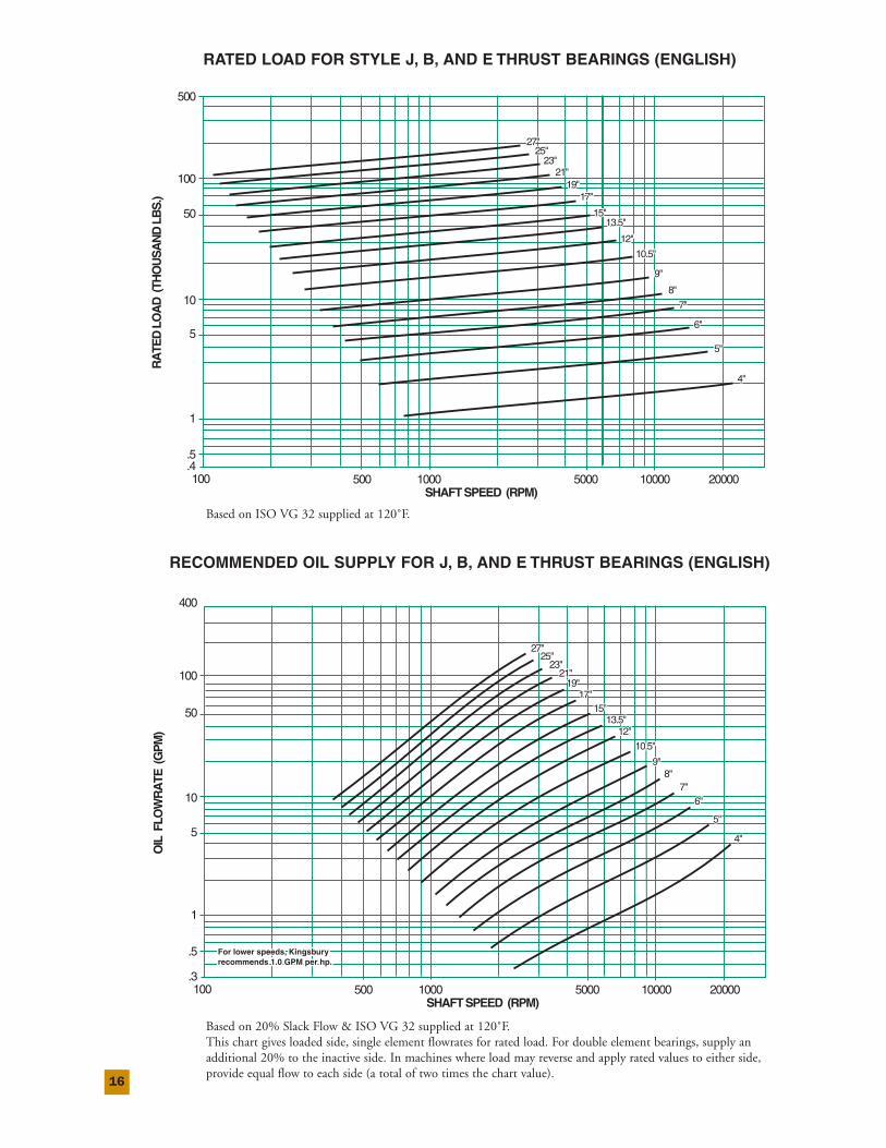
RATED LOAD FOR STYLE J, B, AND E THRUST BEARINGS (ENGLISH)
RECOMMENDED OIL SUPPLY FOR J, B, AND E THRUST BEARINGS (ENGLISH)
7"7"
6"6"
5"5"
4"4"
9"9"
8"8"
10.5"10.5"
13.5"13.5"
12"12"
19"19"17"17"
15"15"
27"27"25"25"
23"23"21"21"
RA
TED
LO
AD
(TH
OU
SA
ND
LB
S.)
.5
.4
1
5
10
50
100
500
100 500 1000 5000 10000 20000SHAFT SPEED (RPM)
7"
6"
5"
4"
9"
8"
10.5"
13.5"
12"
19"17"
15"
27"25"
23"21"
7"7"6"6"
5"5"
4"4"
8"8"9"9"
10.5"10.5"
12"12"
19"19"
27"27"25"25"
13.5"13.5"15"15"
17"17"
21"21"23"23"
7"6"
5"
4"
8"9"
10.5"
12"
19"
OIL
FLO
WR
ATE
(G
PM
)
.5
.3
1
5
10
50
100
400
100 500 1000 5000 10000 20000SHAFT SPEED (RPM)
For lower speeds, Kingsbury For lower speeds, Kingsbury recommends 1.0 GPM per hp.recommends 1.0 GPM per hp.For lower speeds, Kingsbury recommends 1.0 GPM per hp.
27"25"
13.5"15"
17"
21"23"
Based on ISO VG 32 supplied at 120˚F.
Based on 20% Slack Flow & ISO VG 32 supplied at 120˚F.This chart gives loaded side, single element flowrates for rated load. For double element bearings, supply anadditional 20% to the inactive side. In machines where load may reverse and apply rated values to either side,provide equal flow to each side (a total of two times the chart value).
17
J, B, E BEARINGS,
ENGLISH
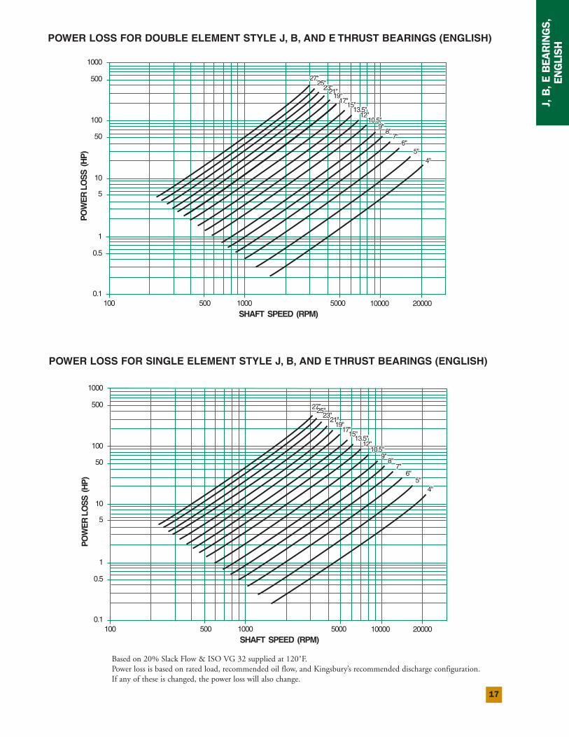
POWER LOSS FOR DOUBLE ELEMENT STYLE J, B, AND E THRUST BEARINGS (ENGLISH)
POWER LOSS FOR SINGLE ELEMENT STYLE J, B, AND E THRUST BEARINGS (ENGLISH)
4"4"5"5"
9"9"8"8"
7"7"6"6"
10.5"10.5"12"12"
13.5"13.5"15"15"
17" 17"19"19"
21"21"23"23"25"25"
27"27"P
OW
ER
LO
SS
(H
P)
0.1
1
0.5
5
10
50
1000
500
100
100 500 1000 5000 10000 20000SHAFT SPEED (RPM)
4"5"
9"8"
7"6"
10.5"12"
13.5"15"
17"19"
21"23"25"
27"
4"4"5"5"
9"9"8"8"
7"7"6"6"
10.5"10.5"12"12"
13.5"13.5"15"15"
17" 17"19"19"
21"21"23"23"
25"25"27"27"
PO
WE
R L
OS
S (
HP
)
0.1
1
0.5
5
10
50
1000
500
100
100 500 1000 5000 10000 20000SHAFT SPEED (RPM)
4"5"
9"8"
7"6"
10.5"12"
13.5"15"
17"19"
21"23"
25"27"
Based on 20% Slack Flow & ISO VG 32 supplied at 120˚F.Power loss is based on rated load, recommended oil flow, and Kingsbury’s recommended discharge configuration.If any of these is changed, the power loss will also change.
18
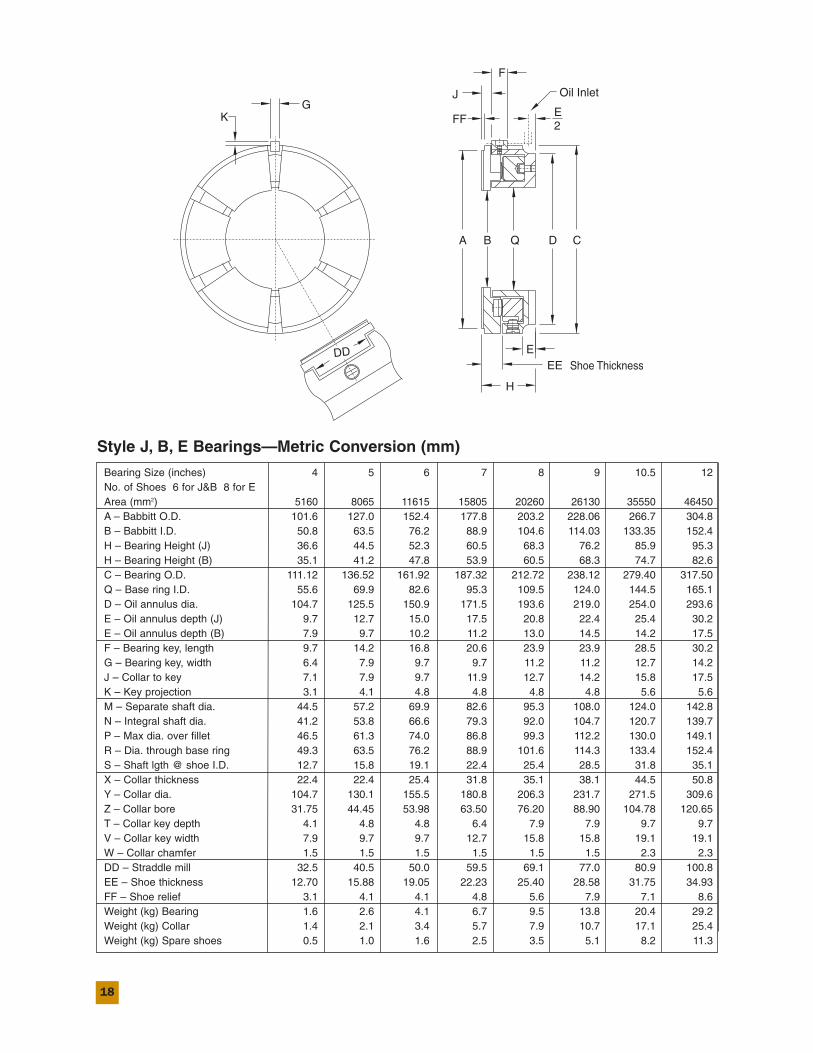
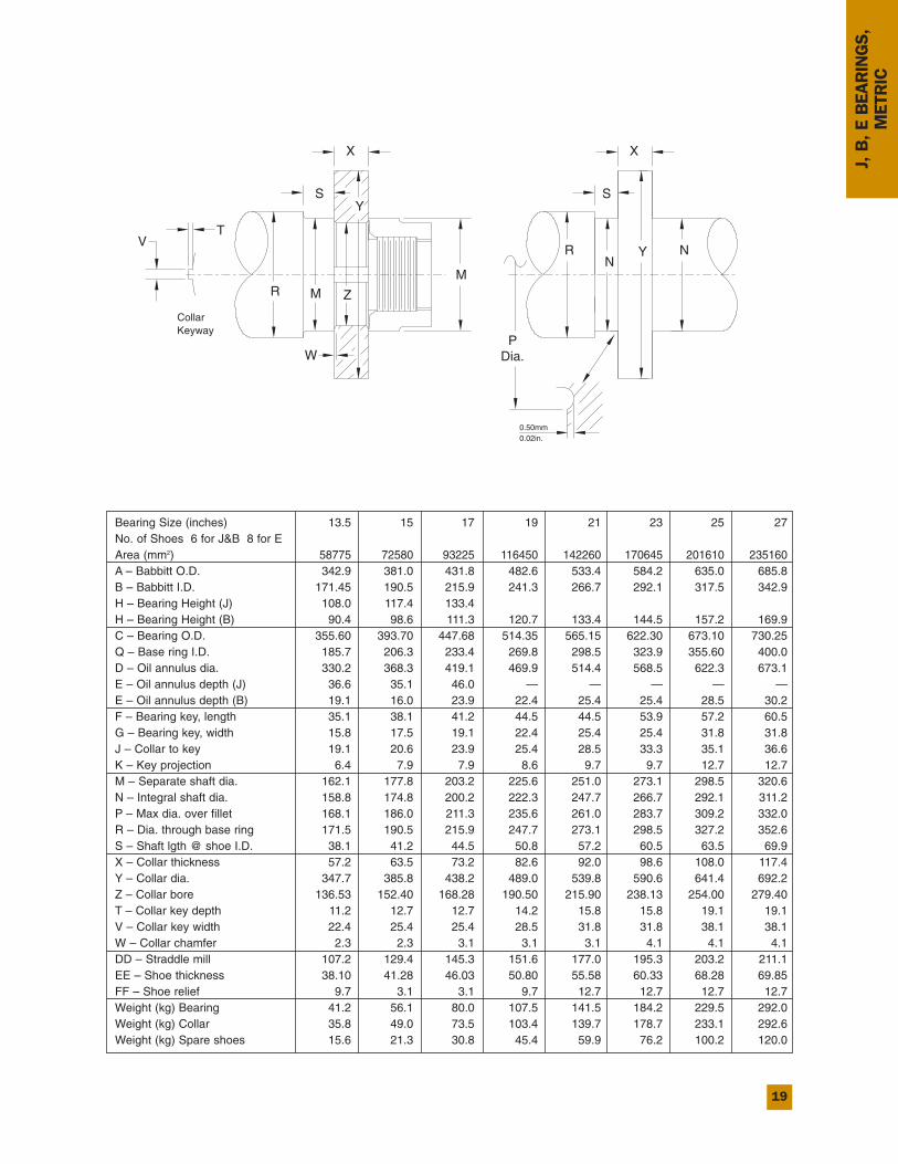
Style J, B, E Bearings—Metric Conversion (mm)
Bearing Size (inches) 4 5 6 7 8 9 10.5 12No. of Shoes 6 for J&B 8 for EArea (mm2) 5160 8065 11615 15805 20260 26130 35550 46450A – Babbitt O.D. 101.6 127.0 152.4 177.8 203.2 228.06 266.7 304.8B – Babbitt I.D. 50.8 63.5 76.2 88.9 104.6 114.03 133.35 152.4H – Bearing Height (J) 36.6 44.5 52.3 60.5 68.3 76.2 85.9 95.3H – Bearing Height (B) 35.1 41.2 47.8 53.9 60.5 68.3 74.7 82.6C – Bearing O.D. 111.12 136.52 161.92 187.32 212.72 238.12 279.40 317.50Q – Base ring I.D. 55.6 69.9 82.6 95.3 109.5 124.0 144.5 165.1D – Oil annulus dia. 104.7 125.5 150.9 171.5 193.6 219.0 254.0 293.6E – Oil annulus depth (J) 9.7 12.7 15.0 17.5 20.8 22.4 25.4 30.2E – Oil annulus depth (B) 7.9 9.7 10.2 11.2 13.0 14.5 14.2 17.5F – Bearing key, length 9.7 14.2 16.8 20.6 23.9 23.9 28.5 30.2G – Bearing key, width 6.4 7.9 9.7 9.7 11.2 11.2 12.7 14.2J – Collar to key 7.1 7.9 9.7 11.9 12.7 14.2 15.8 17.5K – Key projection 3.1 4.1 4.8 4.8 4.8 4.8 5.6 5.6M – Separate shaft dia. 44.5 57.2 69.9 82.6 95.3 108.0 124.0 142.8N – Integral shaft dia. 41.2 53.8 66.6 79.3 92.0 104.7 120.7 139.7P – Max dia. over fillet 46.5 61.3 74.0 86.8 99.3 112.2 130.0 149.1R – Dia. through base ring 49.3 63.5 76.2 88.9 101.6 114.3 133.4 152.4S – Shaft lgth @ shoe I.D. 12.7 15.8 19.1 22.4 25.4 28.5 31.8 35.1X – Collar thickness 22.4 22.4 25.4 31.8 35.1 38.1 44.5 50.8Y – Collar dia. 104.7 130.1 155.5 180.8 206.3 231.7 271.5 309.6Z – Collar bore 31.75 44.45 53.98 63.50 76.20 88.90 104.78 120.65T – Collar key depth 4.1 4.8 4.8 6.4 7.9 7.9 9.7 9.7V – Collar key width 7.9 9.7 9.7 12.7 15.8 15.8 19.1 19.1W – Collar chamfer 1.5 1.5 1.5 1.5 1.5 1.5 2.3 2.3DD – Straddle mill 32.5 40.5 50.0 59.5 69.1 77.0 80.9 100.8EE – Shoe thickness 12.70 15.88 19.05 22.23 25.40 28.58 31.75 34.93FF – Shoe relief 3.1 4.1 4.1 4.8 5.6 7.9 7.1 8.6Weight (kg) Bearing 1.6 2.6 4.1 6.7 9.5 13.8 20.4 29.2Weight (kg) Collar 1.4 2.1 3.4 5.7 7.9 10.7 17.1 25.4Weight (kg) Spare shoes 0.5 1.0 1.6 2.5 3.5 5.1 8.2 11.3
19
Bearing Size (inches) 13.5 15 17 19 21 23 25 27No. of Shoes 6 for J&B 8 for EArea (mm2) 58775 72580 93225 116450 142260 170645 201610 235160A – Babbitt O.D. 342.9 381.0 431.8 482.6 533.4 584.2 635.0 685.8B – Babbitt I.D. 171.45 190.5 215.9 241.3 266.7 292.1 317.5 342.9H – Bearing Height (J) 108.0 117.4 133.4H – Bearing Height (B) 90.4 98.6 111.3 120.7 133.4 144.5 157.2 169.9C – Bearing O.D. 355.60 393.70 447.68 514.35 565.15 622.30 673.10 730.25Q – Base ring I.D. 185.7 206.3 233.4 269.8 298.5 323.9 355.60 400.0D – Oil annulus dia. 330.2 368.3 419.1 469.9 514.4 568.5 622.3 673.1 E – Oil annulus depth (J) 36.6 35.1 46.0 — — — — —E – Oil annulus depth (B) 19.1 16.0 23.9 22.4 25.4 25.4 28.5 30.2F – Bearing key, length 35.1 38.1 41.2 44.5 44.5 53.9 57.2 60.5G – Bearing key, width 15.8 17.5 19.1 22.4 25.4 25.4 31.8 31.8J – Collar to key 19.1 20.6 23.9 25.4 28.5 33.3 35.1 36.6K – Key projection 6.4 7.9 7.9 8.6 9.7 9.7 12.7 12.7M – Separate shaft dia. 162.1 177.8 203.2 225.6 251.0 273.1 298.5 320.6N – Integral shaft dia. 158.8 174.8 200.2 222.3 247.7 266.7 292.1 311.2P – Max dia. over fillet 168.1 186.0 211.3 235.6 261.0 283.7 309.2 332.0R – Dia. through base ring 171.5 190.5 215.9 247.7 273.1 298.5 327.2 352.6S – Shaft lgth @ shoe I.D. 38.1 41.2 44.5 50.8 57.2 60.5 63.5 69.9X – Collar thickness 57.2 63.5 73.2 82.6 92.0 98.6 108.0 117.4Y – Collar dia. 347.7 385.8 438.2 489.0 539.8 590.6 641.4 692.2Z – Collar bore 136.53 152.40 168.28 190.50 215.90 238.13 254.00 279.40T – Collar key depth 11.2 12.7 12.7 14.2 15.8 15.8 19.1 19.1V – Collar key width 22.4 25.4 25.4 28.5 31.8 31.8 38.1 38.1W – Collar chamfer 2.3 2.3 3.1 3.1 3.1 4.1 4.1 4.1DD – Straddle mill 107.2 129.4 145.3 151.6 177.0 195.3 203.2 211.1EE – Shoe thickness 38.10 41.28 46.03 50.80 55.58 60.33 68.28 69.85FF – Shoe relief 9.7 3.1 3.1 9.7 12.7 12.7 12.7 12.7Weight (kg) Bearing 41.2 56.1 80.0 107.5 141.5 184.2 229.5 292.0Weight (kg) Collar 35.8 49.0 73.5 103.4 139.7 178.7 233.1 292.6Weight (kg) Spare shoes 15.6 21.3 30.8 45.4 59.9 76.2 100.2 120.0
J, B, E BEARINGS,
METRIC
K
R
DD
EE
H
EShoe Thickness
KeywayCollar
GOil Inlet
A B Q D
FF
J
E2
F
C
VT
M
W
Z
0.02in.0.50mm
PDia.
SY
M
X
RN
Y
S
X
N
20
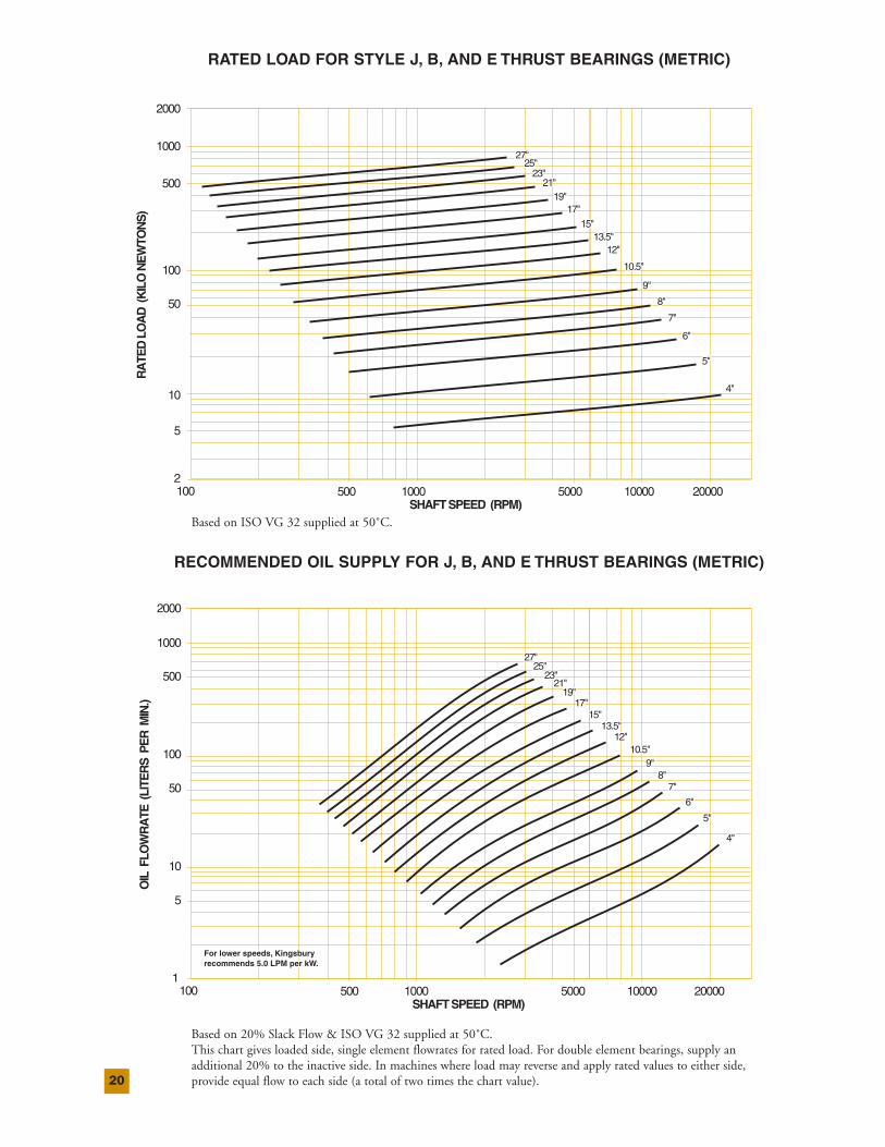
RATED LOAD FOR STYLE J, B, AND E THRUST BEARINGS (METRIC)
RECOMMENDED OIL SUPPLY FOR J, B, AND E THRUST BEARINGS (METRIC)
7"7"
6"6"
5"5"
4"4"
9"9"
8"8"
10.5"10.5"
13.5"13.5"12"12"
19"19"17"17"
15"15"
27"27"25"25"
23"23"21"21"
RA
TED
LO
AD
(K
ILO
NE
WTO
NS
)
2
5
10
50
100
500
1000
2000
100 500 1000 5000 10000 20000SHAFT SPEED (RPM)
7"
6"
5"
4"
9"
8"
10.5"
13.5"12"
19"17"
15"
27"25"
23"21"
7"7"
6"6"
5"5"
4"4"
9"9"8"8"
10.5"10.5"
13.5"13.5"12"12"
19"19"17"17"
15"15"
27"27"25"25"
23"23"21"21"
7"
6"
5"
4"
9"8"
10.5"
13.5"12"
19"17"
15"
27"25"
23"21"
OIL
FLO
WR
ATE
(LI
TER
S P
ER
MIN
.)
1
5
10
50
1000
2000
500
100
100 500 1000 5000 10000 20000SHAFT SPEED (RPM)
For lower speeds, Kingsbury For lower speeds, Kingsbury recommends 5.0 LPM per kW.recommends 5.0 LPM per kW.For lower speeds, Kingsbury recommends 5.0 LPM per kW.
Based on ISO VG 32 supplied at 50˚C.
Based on 20% Slack Flow & ISO VG 32 supplied at 50˚C.This chart gives loaded side, single element flowrates for rated load. For double element bearings, supply anadditional 20% to the inactive side. In machines where load may reverse and apply rated values to either side,provide equal flow to each side (a total of two times the chart value).
21
J, B, E BEARINGS,
METRIC
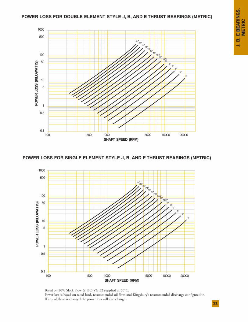
POWER LOSS FOR DOUBLE ELEMENT STYLE J, B, AND E THRUST BEARINGS (METRIC)
POWER LOSS FOR SINGLE ELEMENT STYLE J, B, AND E THRUST BEARINGS (METRIC)
7"7"6"6"
5"5"
4"4"
9"9"8"8"
15"15"
12"12"
17"17"
25"25"
21"21"
27"27"
19"19"
13.5"13.5"
10.5"10.5"
23"23"
PO
WE
R L
OS
S (
KIL
OW
ATT
S)
0.1
1
0.5
5
10
50
1000
500
100
100 500 1000 5000 10000 20000SHAFT SPEED (RPM)
7"6"
5"
4"
9"8"
15"
12"
17"
25"
21"
27"
19"
13.5"
10.5"
23"
PO
WE
R L
OS
S (
KIL
OW
ATT
S)
0.1
1
0.5
5
10
50
1000
500
100
100 500 1000 5000 10000 20000SHAFT SPEED (RPM)
7"6"
5"
4"
9"8"
15"
12"
17"
25"
21"
27"
19"
13.5"
10.5"
23"
Based on 20% Slack Flow & ISO VG 32 supplied at 50˚C.Power loss is based on rated load, recommended oil flow, and Kingsbury’s recommended discharge configuration.If any of these is changed the power loss will also change.
22
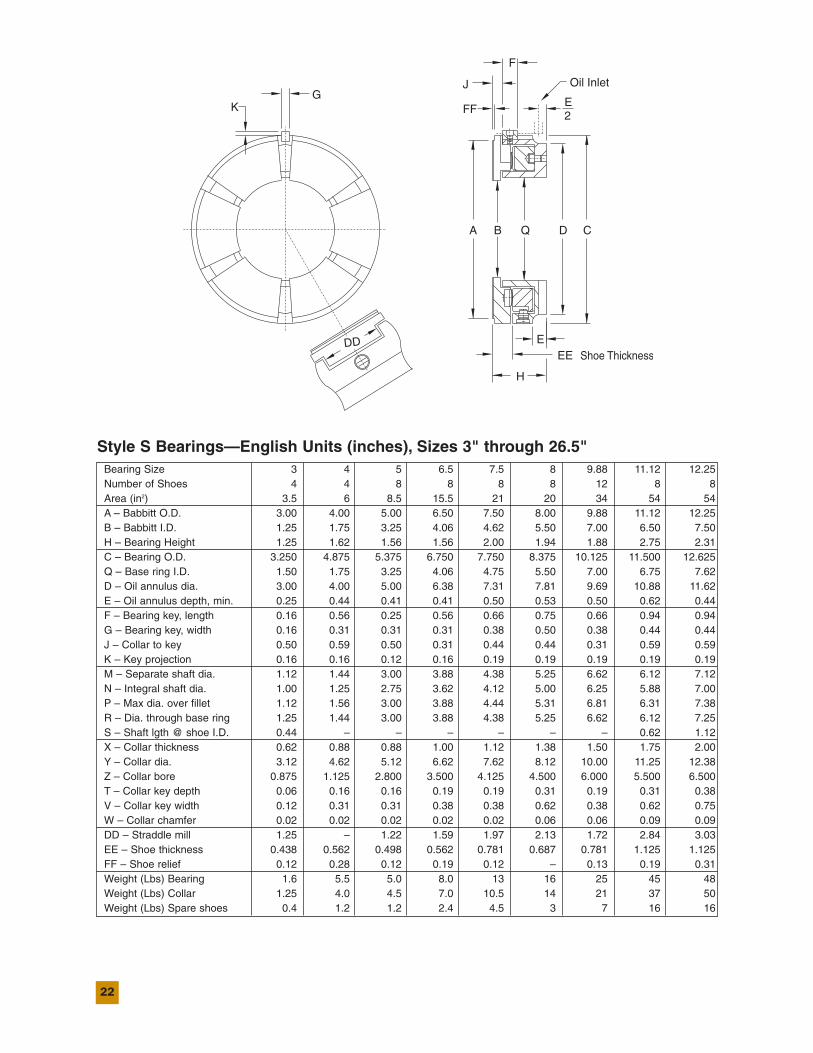
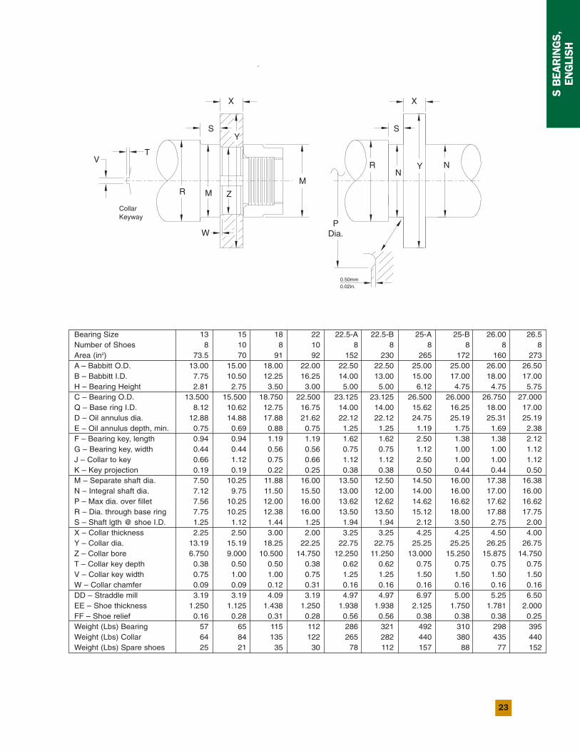
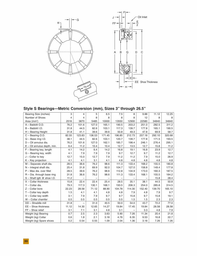
Style S Bearings—English Units (inches), Sizes 3" through 26.5"Bearing Size 3 4 5 6.5 7.5 8 9.88 11.12 12.25Number of Shoes 4 4 8 8 8 8 12 8 8Area (in2) 3.5 6 8.5 15.5 21 20 34 54 54A – Babbitt O.D. 3.00 4.00 5.00 6.50 7.50 8.00 9.88 11.12 12.25B – Babbitt I.D. 1.25 1.75 3.25 4.06 4.62 5.50 7.00 6.50 7.50H – Bearing Height 1.25 1.62 1.56 1.56 2.00 1.94 1.88 2.75 2.31C – Bearing O.D. 3.250 4.875 5.375 6.750 7.750 8.375 10.125 11.500 12.625Q – Base ring I.D. 1.50 1.75 3.25 4.06 4.75 5.50 7.00 6.75 7.62D – Oil annulus dia. 3.00 4.00 5.00 6.38 7.31 7.81 9.69 10.88 11.62E – Oil annulus depth, min. 0.25 0.44 0.41 0.41 0.50 0.53 0.50 0.62 0.44F – Bearing key, length 0.16 0.56 0.25 0.56 0.66 0.75 0.66 0.94 0.94G – Bearing key, width 0.16 0.31 0.31 0.31 0.38 0.50 0.38 0.44 0.44J – Collar to key 0.50 0.59 0.50 0.31 0.44 0.44 0.31 0.59 0.59K – Key projection 0.16 0.16 0.12 0.16 0.19 0.19 0.19 0.19 0.19M – Separate shaft dia. 1.12 1.44 3.00 3.88 4.38 5.25 6.62 6.12 7.12N – Integral shaft dia. 1.00 1.25 2.75 3.62 4.12 5.00 6.25 5.88 7.00P – Max dia. over fillet 1.12 1.56 3.00 3.88 4.44 5.31 6.81 6.31 7.38R – Dia. through base ring 1.25 1.44 3.00 3.88 4.38 5.25 6.62 6.12 7.25S – Shaft lgth @ shoe I.D. 0.44 – – – – – – 0.62 1.12X – Collar thickness 0.62 0.88 0.88 1.00 1.12 1.38 1.50 1.75 2.00Y – Collar dia. 3.12 4.62 5.12 6.62 7.62 8.12 10.00 11.25 12.38Z – Collar bore 0.875 1.125 2.800 3.500 4.125 4.500 6.000 5.500 6.500T – Collar key depth 0.06 0.16 0.16 0.19 0.19 0.31 0.19 0.31 0.38V – Collar key width 0.12 0.31 0.31 0.38 0.38 0.62 0.38 0.62 0.75W – Collar chamfer 0.02 0.02 0.02 0.02 0.02 0.06 0.06 0.09 0.09DD – Straddle mill 1.25 – 1.22 1.59 1.97 2.13 1.72 2.84 3.03EE – Shoe thickness 0.438 0.562 0.498 0.562 0.781 0.687 0.781 1.125 1.125FF – Shoe relief 0.12 0.28 0.12 0.19 0.12 – 0.13 0.19 0.31Weight (Lbs) Bearing 1.6 5.5 5.0 8.0 13 16 25 45 48Weight (Lbs) Collar 1.25 4.0 4.5 7.0 10.5 14 21 37 50Weight (Lbs) Spare shoes 0.4 1.2 1.2 2.4 4.5 3 7 16 16
23
S BEARINGS,
ENGLISH
Bearing Size 13 15 18 22 22.5-A 22.5-B 25-A 25-B 26.00 26.5Number of Shoes 8 10 8 10 8 8 8 8 8 8Area (in2) 73.5 70 91 92 152 230 265 172 160 273A – Babbitt O.D. 13.00 15.00 18.00 22.00 22.50 22.50 25.00 25.00 26.00 26.50B – Babbitt I.D. 7.75 10.50 12.25 16.25 14.00 13.00 15.00 17.00 18.00 17.00H – Bearing Height 2.81 2.75 3.50 3.00 5.00 5.00 6.12 4.75 4.75 5.75C – Bearing O.D. 13.500 15.500 18.750 22.500 23.125 23.125 26.500 26.000 26.750 27.000Q – Base ring I.D. 8.12 10.62 12.75 16.75 14.00 14.00 15.62 16.25 18.00 17.00D – Oil annulus dia. 12.88 14.88 17.88 21.62 22.12 22.12 24.75 25.19 25.31 25.19E – Oil annulus depth, min. 0.75 0.69 0.88 0.75 1.25 1.25 1.19 1.75 1.69 2.38F – Bearing key, length 0.94 0.94 1.19 1.19 1.62 1.62 2.50 1.38 1.38 2.12G – Bearing key, width 0.44 0.44 0.56 0.56 0.75 0.75 1.12 1.00 1.00 1.12J – Collar to key 0.66 1.12 0.75 0.66 1.12 1.12 2.50 1.00 1.00 1.12K – Key projection 0.19 0.19 0.22 0.25 0.38 0.38 0.50 0.44 0.44 0.50M – Separate shaft dia. 7.50 10.25 11.88 16.00 13.50 12.50 14.50 16.00 17.38 16.38N – Integral shaft dia. 7.12 9.75 11.50 15.50 13.00 12.00 14.00 16.00 17.00 16.00P – Max dia. over fillet 7.56 10.25 12.00 16.00 13.62 12.62 14.62 16.62 17.62 16.62R – Dia. through base ring 7.75 10.25 12.38 16.00 13.50 13.50 15.12 18.00 17.88 17.75S – Shaft lgth @ shoe I.D. 1.25 1.12 1.44 1.25 1.94 1.94 2.12 3.50 2.75 2.00X – Collar thickness 2.25 2.50 3.00 2.00 3.25 3.25 4.25 4.25 4.50 4.00Y – Collar dia. 13.19 15.19 18.25 22.25 22.75 22.75 25.25 25.25 26.25 26.75Z – Collar bore 6.750 9.000 10.500 14.750 12.250 11.250 13.000 15.250 15.875 14.750T – Collar key depth 0.38 0.50 0.50 0.38 0.62 0.62 0.75 0.75 0.75 0.75V – Collar key width 0.75 1.00 1.00 0.75 1.25 1.25 1.50 1.50 1.50 1.50W – Collar chamfer 0.09 0.09 0.12 0.31 0.16 0.16 0.16 0.16 0.16 0.16DD – Straddle mill 3.19 3.19 4.09 3.19 4.97 4.97 6.97 5.00 5.25 6.50EE – Shoe thickness 1.250 1.125 1.438 1.250 1.938 1.938 2.125 1.750 1.781 2.000FF – Shoe relief 0.16 0.28 0.31 0.28 0.56 0.56 0.38 0.38 0.38 0.25Weight (Lbs) Bearing 57 65 115 112 286 321 492 310 298 395Weight (Lbs) Collar 64 84 135 122 265 282 440 380 435 440Weight (Lbs) Spare shoes 25 21 35 30 78 112 157 88 77 152
K
R
DD
EE
H
EShoe Thickness
KeywayCollar
GOil Inlet
A B Q D
FF
J
E2
F
C
VT
M
W
Z
0.02in.0.50mm
PDia.
SY
M
X
RN
Y
S
X
N
24
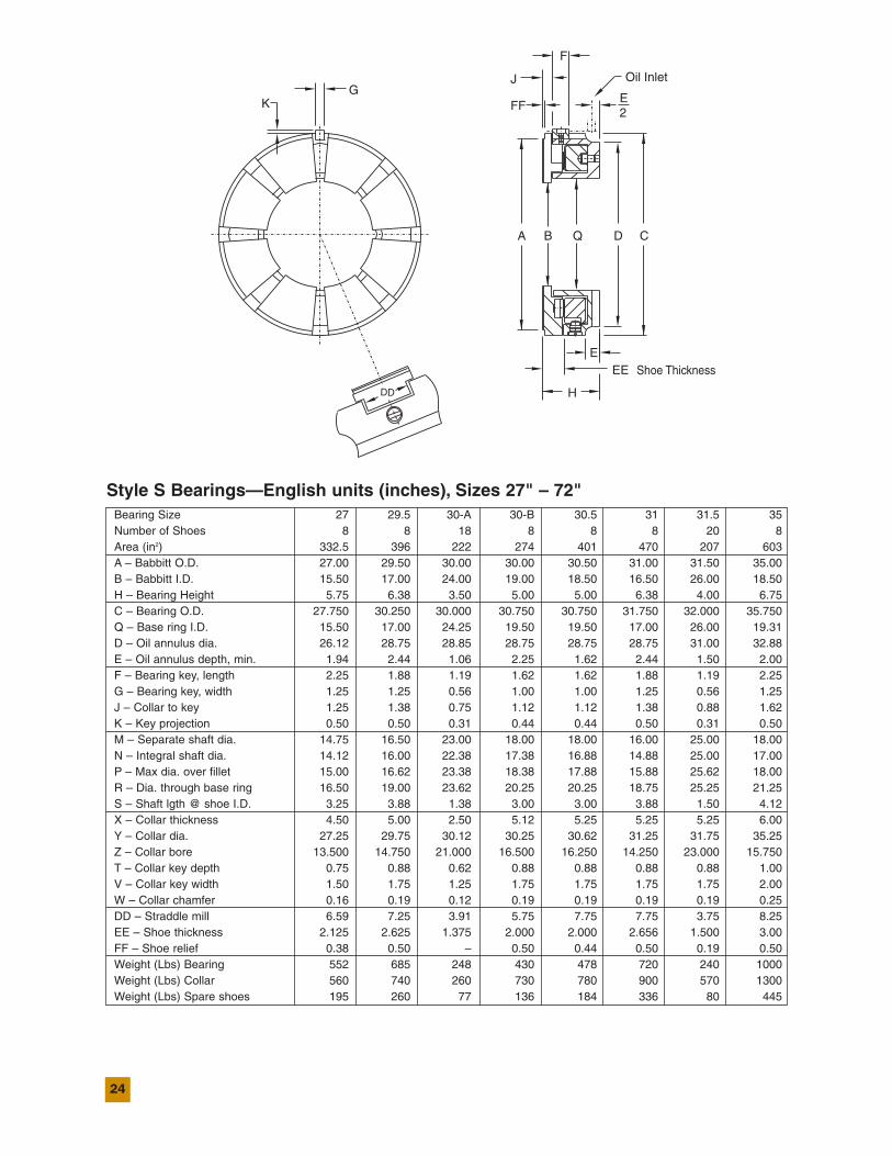
Style S Bearings—English units (inches), Sizes 27" – 72"Bearing Size 27 29.5 30-A 30-B 30.5 31 31.5 35Number of Shoes 8 8 18 8 8 8 20 8Area (in2) 332.5 396 222 274 401 470 207 603A – Babbitt O.D. 27.00 29.50 30.00 30.00 30.50 31.00 31.50 35.00B – Babbitt I.D. 15.50 17.00 24.00 19.00 18.50 16.50 26.00 18.50H – Bearing Height 5.75 6.38 3.50 5.00 5.00 6.38 4.00 6.75C – Bearing O.D. 27.750 30.250 30.000 30.750 30.750 31.750 32.000 35.750Q – Base ring I.D. 15.50 17.00 24.25 19.50 19.50 17.00 26.00 19.31D – Oil annulus dia. 26.12 28.75 28.85 28.75 28.75 28.75 31.00 32.88E – Oil annulus depth, min. 1.94 2.44 1.06 2.25 1.62 2.44 1.50 2.00F – Bearing key, length 2.25 1.88 1.19 1.62 1.62 1.88 1.19 2.25G – Bearing key, width 1.25 1.25 0.56 1.00 1.00 1.25 0.56 1.25J – Collar to key 1.25 1.38 0.75 1.12 1.12 1.38 0.88 1.62K – Key projection 0.50 0.50 0.31 0.44 0.44 0.50 0.31 0.50M – Separate shaft dia. 14.75 16.50 23.00 18.00 18.00 16.00 25.00 18.00N – Integral shaft dia. 14.12 16.00 22.38 17.38 16.88 14.88 25.00 17.00P – Max dia. over fillet 15.00 16.62 23.38 18.38 17.88 15.88 25.62 18.00R – Dia. through base ring 16.50 19.00 23.62 20.25 20.25 18.75 25.25 21.25S – Shaft lgth @ shoe I.D. 3.25 3.88 1.38 3.00 3.00 3.88 1.50 4.12X – Collar thickness 4.50 5.00 2.50 5.12 5.25 5.25 5.25 6.00Y – Collar dia. 27.25 29.75 30.12 30.25 30.62 31.25 31.75 35.25Z – Collar bore 13.500 14.750 21.000 16.500 16.250 14.250 23.000 15.750T – Collar key depth 0.75 0.88 0.62 0.88 0.88 0.88 0.88 1.00V – Collar key width 1.50 1.75 1.25 1.75 1.75 1.75 1.75 2.00W – Collar chamfer 0.16 0.19 0.12 0.19 0.19 0.19 0.19 0.25DD – Straddle mill 6.59 7.25 3.91 5.75 7.75 7.75 3.75 8.25EE – Shoe thickness 2.125 2.625 1.375 2.000 2.000 2.656 1.500 3.00FF – Shoe relief 0.38 0.50 – 0.50 0.44 0.50 0.19 0.50Weight (Lbs) Bearing 552 685 248 430 478 720 240 1000Weight (Lbs) Collar 560 740 260 730 780 900 570 1300Weight (Lbs) Spare shoes 195 260 77 136 184 336 80 445

25
S BEARINGS,
ENGLISH
Bearing Size 39 41 43 45 46 50 54 61 65 72Number of Shoes 8 8 8 8 8 8 8 8 8 8Area (in2) 794 935.5 811.5 1015 937.5 1174.5 1337 1895.5 2342 2480A – Babbitt O.D. 39.00 41.00 43.00 45.00 46.00 50.00 54.00 61.00 65.00 72.00B – Babbitt I.D. 18.00 18.00 25.00 23.50 26.50 27.00 30.00 30.00 28.00 38.00H – Bearing Height 7.25 7.25 8.50 9.00 9.00 10.00 10.63 11.13 12.56 14.50C – Bearing O.D. 41.250 42.500 44.000 46.000 47.000 50.750 54.750 61.750 65.750 73.000Q – Base ring I.D. 20.25 20.25 26.00 27.63 26.75 30.00 31.50 33.75 31.00 40.00D – Oil annulus dia. 36.75 36.75 41.75 44.00 44.00 48.25 51.75 56.75 61.75 69.00E – Oil annulus depth, min. 1.69 1.69 2.00 3.88 3.75 3.25 4.25 4.00 4.44 5.00F – Bearing key, length 3.25 3.25 2.75 1.75 1.75 3.00 2.00 2.00 5.00 5.00G – Bearing key, width 1.75 1.75 1.75 1.75 1.75 2.00 2.00 2.00 2.75 2.75J – Collar to key 1.88 1.88 2.06 3.00 3.00 3.25 3.25 3.75 3.13 3.88K – Key projection .63 .63 .63 1.25 1.25 .75 1.00 1.00 1.50 1.38M – Separate shaft dia. 15.75 15.75 23.75 22.25 25.25 25.50 28.50 28.50 26.25 36.25N – Integral shaft dia. 14.88 14.88 22.75 21.25 24.00 24.50 27.50 27.50 25.25 35.25P – Max dia. over fillet 17.13 17.13 24.13 23.50 25.50 26.00 29.00 29.00 27.00 37.00R – Dia. through base ring 23.00 23.65 27.00 25.50 28.75 31.50 33.75 37.00 34.75 44.00S – Shaft lgth @ shoe I.D. 4.50 4.50 5.00 5.50 5.00 6.00 6.63 7.00 7.50 8.75X – Collar thickness 7.00 7.00 7.25 7.63 7.63 9.00 9.50 10.50 11.00 11.50Y – Collar dia. 39.50 42.00 43.50 45.50 46.50 50.50 54.50 61.50 65.50 72.75Z – Collar bore 14.000 14.000 22.000 20.750 23.250 23.500 26.500 26.500 24.250 34.250T – Collar key depth 1.13 1.13 1.13 1.13 1.13 1.25 1.25 1.38 1.38 1.50V – Collar key width 2.25 2.25 2.25 2.25 2.25 2.50 2.50 2.75 2.75 2.75W – Collar chamfer .38 .38 .38 .38 .38 .50 .50 .63 .63 .75DD – Straddle mill 9.19 9.19 11.09 11.09 11.97 12.94 14.94 16.69 17.69 16.88EE – Shoe thickness 3.929 3.312 3.625 3.625 3.750 4.250 4.500 5.000 5.500 6.125FF – Shoe relief 1.11 .11 .24 .49 .24 .24 .37 .36 .49 .61Weight (Lbs) Bearing 1650 1800 2075 2100 2300 2900 3700 5200 7500 9500Weight (Lbs) Collar 2045 2165 2760 2780 2750 4000 4800 7200 9100 10500Weight (Lbs) Spare shoes 666 720 700 830 820 1130 1380 2100 3000 3400
K
R
DD
EE
H
EShoe Thickness
KeywayCollar
GOil Inlet
A B Q D
FF
J
E2
F
C
VT
M
W
Z
0.02in.0.50mm
PDia.
SY
M
X
RN
Y
S
X
N
26
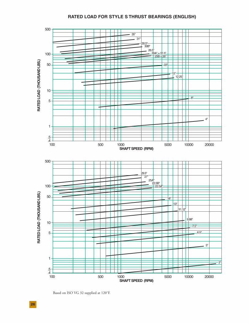
RATED LOAD FOR STYLE S THRUST BEARINGS (ENGLISH)
4"4"
8"8"
12.25"12.25"15"15"
22"22"
25B+26"25B + 26"
26.5"26.5"
31"31"
30A"+31.5"30A" + 31.5"
35"35"
30.5"30.5"30B"30B"
4"
8"
12.25"15"
22"
RA
TED
LOA
D(T
HO
US
AN
DLB
S.)
.5
.4
1
5
10
50
100
500
100 500 1000 5000 10000 20000SHAFTSPEED (RPM)
25B+26"
26.5"
31"
30A"+31.5"
35"
30.5"30B"
7.5"7.5"
6.5"6.5"
3"3"
5"5"
9.88"9.88"
11.12"
13"13"
11.12"11.12"
18"18"
22.5B"22.5B"22.5A"22.5A"
25A"25A"
29.5"29.5"27"27"
7.5"
6.5"
3"
5"
9.88"
11.12"
13"
18"
RA
TED
LOA
D(T
HO
US
AN
DLB
S.)
.5
.4
1
5
10
50
100
500
100 500 1000 5000 10000 20000SHAFTSPEED (RPM)
22.5B"22.5A"
25A"
29.5"27"
Based on ISO VG 32 supplied at 120˚F.
27
SBEARINGS,
ENGLISH
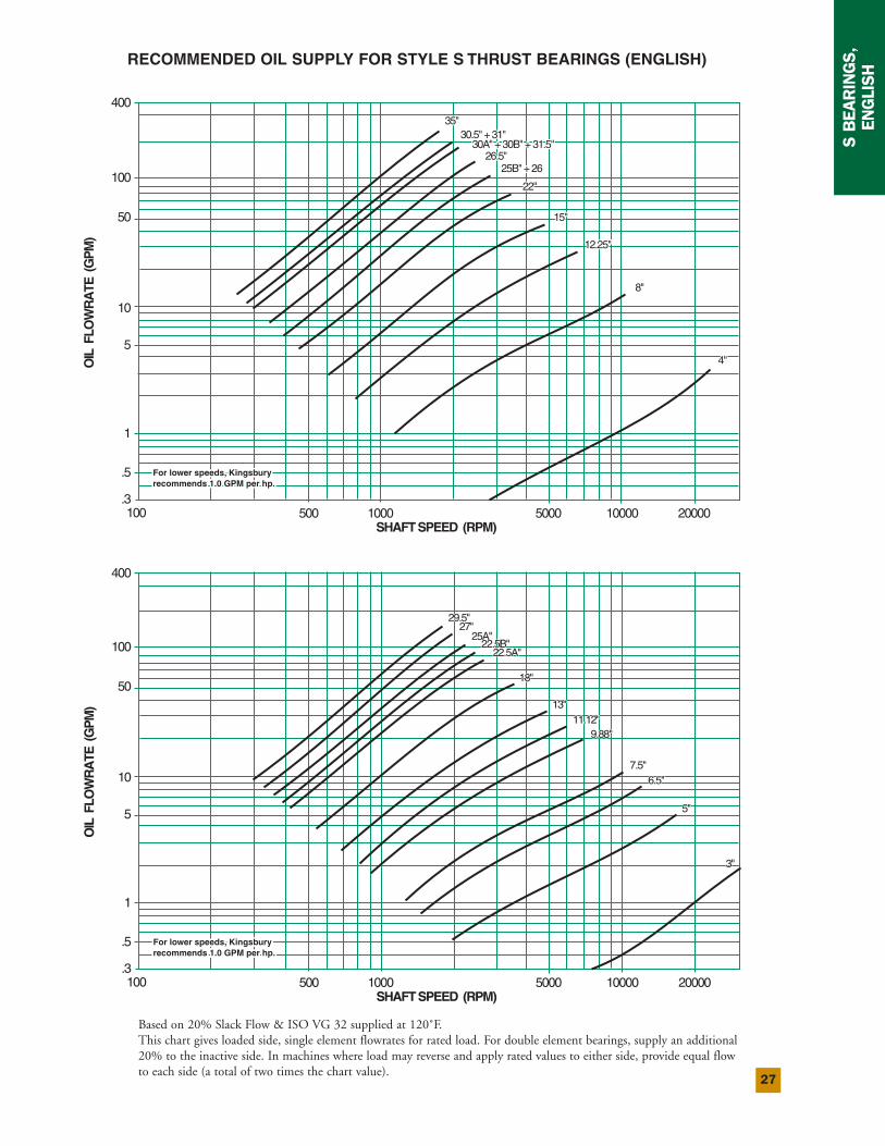
RECOMMENDED OIL SUPPLY FOR STYLE S THRUST BEARINGS (ENGLISH)
8"8"
4"4"
12.25"12.25"
15"15"
22"22"
25B"+2625B" + 2626.5"26.5"
35"35"30.5"+31"30.5" + 31"
30A"+30B"+31.5"30A" + 30B" + 31.5"
OIL
FLO
WR
ATE
(GP
M)
.5
.3
1
5
10
50
100
400
100 500 1000 5000 10000 20000SHAFTSPEED (RPM)
For lower speeds, KingsburyFor lower speeds, Kingsbury recommends 1.0 GPM per hp.recommends 1.0 GPM per hp.For lower speeds, Kingsburyrecommends 1.0 GPM per hp.
8"
4"
12.25"
15"
22"
25B"+2626.5"
35"30.5"+31"
30A"+30B"+31.5"
7.5"7.5"6.5"6.5"
5"5"
3"3"
9.88"9.88"11.12"11.12"
13"13"
OIL
FLO
WR
ATE
(GP
M)
OIL
FLO
WR
ATE
(G
PM
)
.5.5
.3.3
11
55
1010
5050
100100
100100 500500 10001000 50005000 1000010000 2000020000SHAFTSPEED (RPM)SHAFT SPEED (RPM)
For lower speeds, KingsburyFor lower speeds, Kingsbury recommends 1.0 GPM per hp.recommends 1.0 GPM per hp.For lower speeds, KingsburyFor lower speeds, Kingsbury recommends 1.0 GPM per hp.recommends 1.0 GPM per hp.
22.5B"22.5B"22.5A"22.5A"
25A"25A"
29.5"29.5"27"27"
18"18"
7.5"6.5"
5"
3"
9.88"11.12"
13"
18"
OIL
FLO
WR
ATE
(GP
M)
.5
.3
1
5
10
50
100
400
100 500 1000 5000 10000 20000SHAFTSPEED (RPM)
For lower speeds, KingsburyFor lower speeds, Kingsbury recommends 1.0 GPM per hp.recommends 1.0 GPM per hp.For lower speeds, Kingsburyrecommends 1.0 GPM per hp.
22.5B"22.5A"
25A"
29.5"27"
Based on 20% Slack Flow & ISO VG 32 supplied at 120˚F.This chart gives loaded side, single element flowrates for rated load. For double element bearings, supply an additional20% to the inactive side. In machines where load may reverse and apply rated values to either side, provide equal flowto each side (a total of two times the chart value).
28
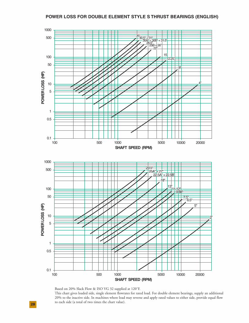
POWER LOSS FOR DOUBLE ELEMENT STYLE S THRUST BEARINGS (ENGLISH)
4"4"
8"8"
12.25"12.25"15"15"
22"22"
26.5"26.5"25B+26"25B + 26"
35"35"30.5"+31"30.5" + 31"
30A"+30B"+31.5"30A" + 30B" + 31.5"P
OW
ER
LOS
S(H
P)
0.1
1
0.5
5
10
50
1000
500
100
100 500 1000 5000 10000 20000SHAFT SPEED (RPM)
4"
8"
12.25"15"
22"
26.5"25B+26"
35"30.5"+31"
30A"+30B"+31.5"P
OW
ER
LOS
S(H
P)
PO
WE
R L
OS
S (
HP
)
0.10.1
11
0.50.5
55
1010
5050
10001000
500500
100100
100100 500500 10001000 50005000 1000010000 2000020000SHAFT SPEED (RPM)SHAFT SPEED (RPM)
4"4"3"3"
7.5"7.5"
5"5"
6.5"6.5"
9.88"9.88"11.12"11.12"
13"13"
18"18"
25A"+27"25A" + 27"29.5"29.5"
22.5A"+22.5B"22.5A" + 22.5B"
PO
WE
RLO
SS
(HP
)
0.1
1
0.5
5
10
50
1000
500
100
100 500 1000 5000 10000 20000SHAFT SPEED (RPM)
4"4"3"
7.5"
5"
6.5"
9.88"11.12"
13"
18"
25A"+27"29.5"
22.5A"+22.5B"
Based on 20% Slack Flow & ISO VG 32 supplied at 120˚F.This chart gives loaded side, single element flowrates for rated load. For double element bearings, supply an additional20% to the inactive side. In machines where load may reverse and apply rated values to either side, provide equal flowto each side (a total of two times the chart value).
29
SBEARINGS,
ENGLISH
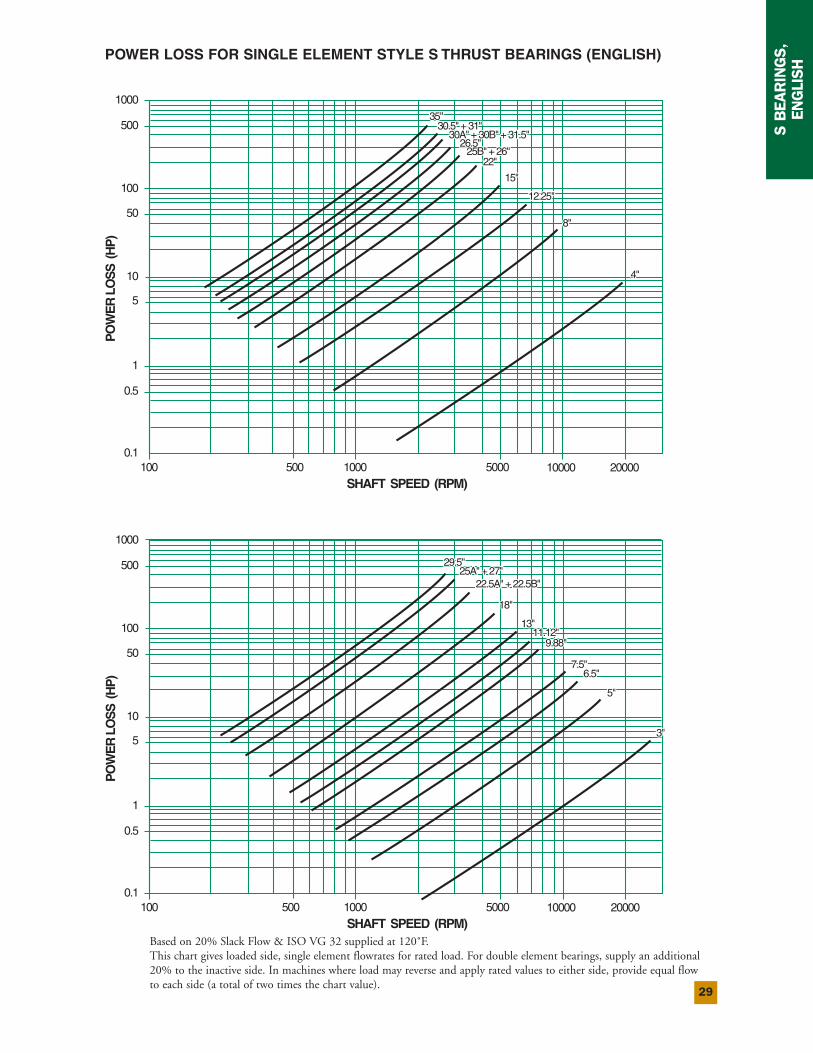
POWER LOSS FOR SINGLE ELEMENT STYLE S THRUST BEARINGS (ENGLISH)
4"4"
8"8"
12.25"12.25"
15"15"
22"22"
26.5"26.5"25B"+26"25B" + 26"
30A"+30B"+31.5"30A" + 30B" + 31.5"
35"35"30.5"+31"30.5" + 31"
PO
WE
RLO
SS
(HP
)
0.1
1
0.5
5
10
50
1000
500
100
100 500 1000 5000 10000 20000SHAFT SPEED (RPM)
4"
8"
12.25"
15"
22"
26.5"25B"+26"
30A"+30B"+31.5"
35"30.5"+31"
3"3"
7.5"7.5"
5"5"
6.5"6.5"
9.88"9.88"11.12"11.12"
13"13"
18"18"
22.5A"+22.5B"22.5A" + 22.5B"25A"+27"25A" + 27"
29.5"29.5"
PO
WE
RLO
SS
(HP
)
0.1
1
0.5
5
10
50
1000
500
100
100 500 1000 5000 10000 20000SHAFT SPEED (RPM)
3"
7.5"
5"
6.5"
9.88"11.12"
13"
18"
22.5A"+22.5B"25A"+27"
29.5"
Based on 20% Slack Flow & ISO VG 32 supplied at 120˚F.This chart gives loaded side, single element flowrates for rated load. For double element bearings, supply an additional20% to the inactive side. In machines where load may reverse and apply rated values to either side, provide equal flowto each side (a total of two times the chart value).
30
Style S Bearings—Metric Conversion (mm), Sizes 3” through 26.5”Bearing Size (inches) 3 4 5 6.5 7.5 8 9.88 11.12 12.25Number of Shoes 4 4 8 8 8 8 12 8 8Area (mm2) 2516 3870 5485 10000 13550 12900 22580 34840 34840A – Babbitt O.D. 76.2 101.6 127.0 165.1 190.5 203.2 251.0 282.5 311.2B – Babbitt I.D. 31.8 44.5 82.6 103.1 117.3 139.7 177.8 165.1 190.5H – Bearing Height 31.8 41.1 39.6 39.6 50.8 49.3 47.8 69.9 58.7C – Bearing O.D. 82.55 123.83 136.53 171.45 196.85 212.73 257.18 292.10 320.68Q – Base ring I.D. 38.1 44.5 82.6 103.1 120.7 139.7 177.8 171.5 193.5D – Oil annulus dia. 76.2 101.6 127.0 162.1 185.7 198.4 246.1 276.4 295.1E – Oil annulus depth, min. 6.4 11.2 10.4 10.4 12.7 13.5 12.7 15.8 11.2F – Bearing key, length 4.1 14.2 6.4 14.2 16.8 19.1 16.8 23.9 12.7G – Bearing key, width 4.1 7.9 7.9 7.9 9.7 12.7 9.7 11.2 12.7J – Collar to key 12.7 15.0 12.7 7.9 11.2 11.2 7.9 15.0 26.9K – Key projection 4.1 4.1 3.1 4.1 4.8 4.8 4.8 4.8 4.8M – Separate shaft dia. 28.5 36.6 76.2 98.6 111.3 133.4 168.2 155.5 180.8N – Integral shaft dia. 25.4 31.8 69.9 92.0 104.7 127.0 158.8 149.4 177.8P – Max dia. over fillet 28.5 39.6 76.2 98.6 112.8 134.9 173.0 160.3 187.5R – Dia. through base ring 31.8 36.6 76.2 98.6 111.3 133.4 168.1 155.5 184.2S – Shaft lgth @ shoe I.D. 11.2 – – – – – – 15.8 28.4X – Collar thickness 15.8 22.4 22.4 25.4 28.5 35.1 38.1 44.5 50.8Y – Collar dia. 79.3 117.3 130.1 168.1 193.5 206.3 254.0 285.8 314.5Z – Collar bore 22.23 28.58 71.12 88.90 104.78 114.30 152.40 139.70 165.10T – Collar key depth 1.5 4.1 4.1 4.8 4.8 7.9 4.8 7.9 9.7V – Collar key width 3.1 7.9 7.9 9.7 9.7 15.8 9.7 15.8 19.1W – Collar chamfer 0.5 0.5 0.5 0.5 0.5 1.5 1.5 2.3 2.3DD – Straddle mill 31.8 – 31.0 40.5 50.0 54.0 43.7 72.2 77.0EE – Shoe thickness 11.12 14.30 12.65 14.27 19.84 17.45 19.84 28.58 28.58FF – Shoe relief 3.1 7.1 3.1 4.8 3.1 – 3.3 4.8 7.9Weight (kg) Bearing 0.7 2.5 2.3 3.63 5.90 7.26 11.34 20.4 21.8Weight (kg) Collar 0.6 1.8 2.1 3.18 4.76 6.35 9.53 16.8 22.7Weight (kg) Spare shoes 0.2 0.54 0.55 1.09 2.04 1.36 3.18 7.26 7.26

31
SBEARINGS,
METRIC
Bearing Size (inches) 13 15 18 22 22.5-A 22.5-B 25-A 25-B 26 26.5Number of Shoes 8 10 8 10 8 8 8 8 8 8Area (mm2) 46645 45160 58710 59355 98065 148385 170965 110965 103225 176130A – Babbitt O.D. 330.2 381.0 457.2 558.8 571.5 571.5 635.0 635.0 660.4 673.1B – Babbitt I.D. 196.9 266.7 311.2 412.8 355.6 330.2 381.0 431.8 457.2 431.8H – Bearing Height 71.4 69.9 88.9 76.2 127.0 127.0 155.4 120.7 120.7 146.1C – Bearing O.D. 342.90 393.70 476.25 571.50 587.38 587.38 673.10 660.40 679.45 685.80Q – Base ring I.D. 206.2 269.7 323.9 425.5 355.6 355.6 396.7 412.8 457.2 431.8D – Oil annulus dia. 327.2 378.0 454.2 549.1 561.8 561.8 628.7 639.8 642.9 639.8E – Oil annulus depth, min. 19.1 17.5 22.4 19.1 31.8 31.8 30.2 44.5 42.9 60.5F – Bearing key, length 23.9 23.9 30.2 30.2 41.1 41.1 63.5 35.1 35.1 53.8G – Bearing key, width 11.2 11.2 14.2 14.2 19.1 19.1 28.4 25.4 25.4 28.4J – Collar to key 16.8 28.4 19.1 16.8 28.4 28.4 63.5 25.4 25.4 28.4K – Key projection 4.8 4.8 5.6 6.4 9.7 9.7 12.7 11.2 11.2 12.7M – Separate shaft dia. 190.5 260.4 301.8 406.4 342.9 317.5 368.3 406.4 441.5 416.1N – Integral shaft dia. 180.8 247.7 292.1 393.7 330.2 304.8 355.6 406.4 431.8 406.4P – Max dia. over fillet 192.0 260.4 304.8 406.4 345.9 320.5 371.3 422.1 447.5 422.1R – Dia. through base ring 196.9 260.4 314.5 406.4 342.9 345.9 384.0 457.2 454.2 450.9S – Shaft lgth @ shoe I.D. 31.8 28.4 36.6 31.8 49.3 49.3 53.8 88.9 69.9 50.8X – Collar thickness 57.2 63.5 76.2 50.8 82.6 82.6 108.0 108.0 114.3 101.6Y – Collar dia. 335.0 385.8 463.6 565.2 577.9 577.9 641.4 641.4 666.8 679.5Z – Collar bore 171.45 228.60 266.70 374.65 311.15 285.75 330.20 387.35 403.23 374.65T – Collar key depth 9.7 12.7 12.7 9.7 15.7 15.7 19.1 19.1 19.1 19.1V – Collar key width 19.1 25.4 25.4 19.1 31.8 31.8 38.1 38.1 38.1 38.1W – Collar chamfer 2.3 2.3 3.0 7.9 4.1 4.1 4.1 4.1 4.1 4.1DD – Straddle mill 81.0 81.0 104.0 81.0 126.2 126.2 177.0 127.0 133.4 165.1EE – Shoe thickness 31.75 28.58 36.53 31.75 49.23 49.23 53.98 44.45 45.24 50.80FF – Shoe relief 4.1 7.1 7.9 7.1 14.2 14.2 9.7 9.7 9.7 6.4Weight (kg) Bearing 25.9 29.5 52.2 50.8 129.7 145.6 223.2 140.6 135.2 179.2Weight (kg) Collar 29 38.1 61.2 55.3 120.2 127.9 199.6 172.4 197.3 199.6Weight (kg) Spare shoes 11.3 9.5 15.9 13.6 35.4 50.8 71.2 39.9 34.9 68.9
R
KeywayCollar
VT
M
W
Z
0.02in.0.50mm
PDia.
SY
M
X
RN
Y
S
X
N
32
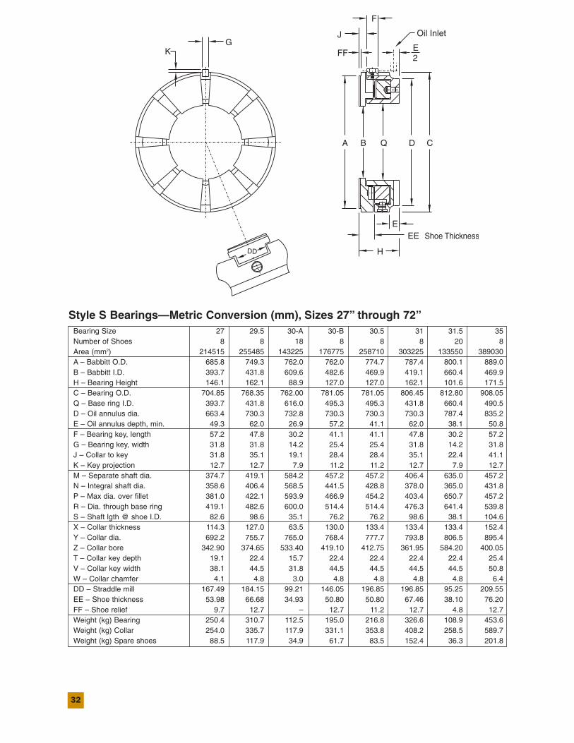
Style S Bearings—Metric Conversion (mm), Sizes 27” through 72”Bearing Size 27 29.5 30-A 30-B 30.5 31 31.5 35Number of Shoes 8 8 18 8 8 8 20 8Area (mm2) 214515 255485 143225 176775 258710 303225 133550 389030A – Babbitt O.D. 685.8 749.3 762.0 762.0 774.7 787.4 800.1 889.0B – Babbitt I.D. 393.7 431.8 609.6 482.6 469.9 419.1 660.4 469.9H – Bearing Height 146.1 162.1 88.9 127.0 127.0 162.1 101.6 171.5C – Bearing O.D. 704.85 768.35 762.00 781.05 781.05 806.45 812.80 908.05Q – Base ring I.D. 393.7 431.8 616.0 495.3 495.3 431.8 660.4 490.5D – Oil annulus dia. 663.4 730.3 732.8 730.3 730.3 730.3 787.4 835.2E – Oil annulus depth, min. 49.3 62.0 26.9 57.2 41.1 62.0 38.1 50.8F – Bearing key, length 57.2 47.8 30.2 41.1 41.1 47.8 30.2 57.2G – Bearing key, width 31.8 31.8 14.2 25.4 25.4 31.8 14.2 31.8J – Collar to key 31.8 35.1 19.1 28.4 28.4 35.1 22.4 41.1K – Key projection 12.7 12.7 7.9 11.2 11.2 12.7 7.9 12.7M – Separate shaft dia. 374.7 419.1 584.2 457.2 457.2 406.4 635.0 457.2N – Integral shaft dia. 358.6 406.4 568.5 441.5 428.8 378.0 365.0 431.8P – Max dia. over fillet 381.0 422.1 593.9 466.9 454.2 403.4 650.7 457.2R – Dia. through base ring 419.1 482.6 600.0 514.4 514.4 476.3 641.4 539.8S – Shaft lgth @ shoe I.D. 82.6 98.6 35.1 76.2 76.2 98.6 38.1 104.6X – Collar thickness 114.3 127.0 63.5 130.0 133.4 133.4 133.4 152.4Y – Collar dia. 692.2 755.7 765.0 768.4 777.7 793.8 806.5 895.4Z – Collar bore 342.90 374.65 533.40 419.10 412.75 361.95 584.20 400.05T – Collar key depth 19.1 22.4 15.7 22.4 22.4 22.4 22.4 25.4V – Collar key width 38.1 44.5 31.8 44.5 44.5 44.5 44.5 50.8W – Collar chamfer 4.1 4.8 3.0 4.8 4.8 4.8 4.8 6.4DD – Straddle mill 167.49 184.15 99.21 146.05 196.85 196.85 95.25 209.55EE – Shoe thickness 53.98 66.68 34.93 50.80 50.80 67.46 38.10 76.20FF – Shoe relief 9.7 12.7 – 12.7 11.2 12.7 4.8 12.7Weight (kg) Bearing 250.4 310.7 112.5 195.0 216.8 326.6 108.9 453.6Weight (kg) Collar 254.0 335.7 117.9 331.1 353.8 408.2 258.5 589.7Weight (kg) Spare shoes 88.5 117.9 34.9 61.7 83.5 152.4 36.3 201.8

33
SBEARINGS,
METRIC
Bearing Size 39 41 43 45 46 50 54 61 65 72Number of Shoes 8 8 8 8 8 8 8 8 8 8Area (mm2) 512,257 603,547 523,547 654,837 604,383 757,740 862,579 1,222,900 1,510,965 1,600,000A – Babbitt O.D. 990.6 1041.4 1092.2 1143.0 1168.4 1270.0 1371.6 1549.4 1651.0 1828.8B – Babbitt I.D. 457.2 457.2 635.0 596.9 673.1 685.8 762.0 762.0 711.2 965.2H – Bearing Height 184.1 184.1 215.9 228.6 228.6 254.0 270.0 282.7 319.0 210.2C – Bearing O.D. 1047.75 1079.50 1117.60 1168.40 1193.80 1289.05 1390.65 1568.45 1670.05 1854.20Q – Base ring I.D. 514.3 514.3 660.4 701.8 679.4 900.0 800.1 857.2 787.4 1016.0D – Oil annulus dia. 933.4 933.4 1060.4 1117.6 1117.6 1225.5 1314.4 1441.4 1568.4 1753.0E – Oil annulus depth, min. 42.9 42.9 50.8 98.4 95.2 82.5 107.9 101.6 112.7 127.0F – Bearing key, length 82.5 82.5 69.8 44.4 44.4 76.2 50.8 50.8 127.0 127.0G – Bearing key, width 44.4 44.4 44.4 44.4 44.4 50.8 50.8 50.8 69.8 69.8J – Collar to key 47.7 47.7 52.3 76.4 76.4 82.5 82.5 95.2 79.5 98.4K – Key projection 16.0 16.0 16.0 31.7 31.7 19.0 25.4 25.4 38.1 35.0M – Separate shaft dia. 400.0 400.0 603.2 565.1 641.3 647.7 723.9 723.9 666.7 920.7N – Integral shaft dia. 377.8 377.8 577.8 539.7 609.6 622.3 698.5 698.5 637.5 895.3P – Max dia. over fillet 435.1 435.1 612.9 596.9 647.7 660.4 736.6 736.6 685.8 939.8R – Dia. through base ring 584.2 600.7 685.8 647.7 730.2 800.1 857.2 939.8 882.6 1117.6S – Shaft lgth @ shoe I.D. 114.3 114.3 127.0 139.7 127.0 152.4 168.4 177.8 190.5 222.2X – Collar thickness 177.8 177.8 184.1 193.8 193.8 228.6 241.3 266.7 279.4 292.1Y – Collar dia. 1003.3 1066.8 1104.9 1155.7 1181.1 1282.7 1384.4 1562.1 1663.7 1847.8Z – Collar bore 355.60 355.60 558.80 527.05 590.55 596.90 673.10 673.10 615.95 869.95T – Collar key depth 28.7 28.7 28.7 28.7 28.7 31.7 31.7 35.0 35.0 38.1V – Collar key width 57.1 57.1 57.1 57.1 57.1 63.5 63.5 69.8 69.8 69.8W – Collar chamfer 9.3 9.6 9.6 9.6 9.6 12.7 12.7 16.0 16.0 19.0DD – Straddle mill 233.4 233.4 281.8 281.8 304.4 328.6 379.4 423.9 449.3 428.6EE – Shoe thickness 83.62 84.12 92.07 92.07 95.25 107.95 114.30 127.00 139.70 155.57FF – Shoe relief 28.2 2.8 6.1 12.4 6.1 6.1 9.4 9.1 12.4 15.5Weight (kg) Bearing 748 816 941 953 1043 1315 1678 2359 3402 4309Weight (kg) Collar 928 982 1252 1261 1247 1814 2177 3266 4128 4763Weight (kg) Spare shoes 302 327 318 376 372 513 626 953 1361 1542
R
KeywayCollar
VT
M
W
Z
0.02in.0.50mm
PDia.
SY
M
X
RN
Y
S
X
N
34
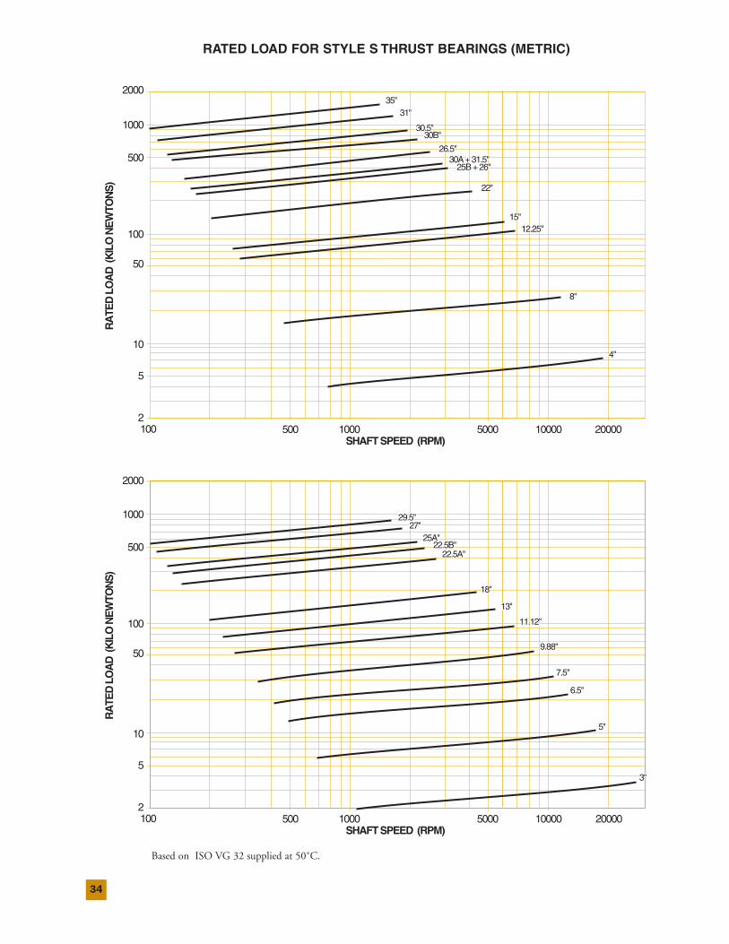
RATED LOAD FOR STYLE S THRUST BEARINGS (METRIC)
RA
TED
LOA
D(K
ILO
NE
WTO
NS
)
2
5
10
50
100
500
1000
2000
100 500 1000 5000 10000 20000SHAFTSPEED (RPM)
8"8"
4"4"
12.25"12.25"15"15"
22"22"
26.5"26.5"
35"35"31"31"
30.5"30.5"30B"30B"
30A+31.5"30A + 31.5"25B+26"25B + 26"
8"
4"
12.25"15"
22"
26.5"
35"31"
30.5"30B"
30A+31.5"25B+26"
RA
TED
LOA
D(K
ILO
NE
WTO
NS
)
2
5
10
50
100
500
1000
2000
100 500 1000 5000 10000 20000SHAFTSPEED (RPM)
7.5"7.5"
6.5"6.5"
3"3"
5"5"
9.88"9.88"
11.12"11.12"
13"13"
18"18"
22.5B"22.5B"22.5A"22.5A"
25A"25A"
29.5"29.5"27"27"
7.5"
6.5"
3"
5"
9.88"
11.12"
13"
18"
22.5B"22.5A"
25A"
29.5"27"
Based on ISO VG 32 supplied at 50˚C.
35
SBEARINGS,
METRIC
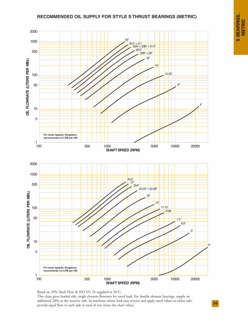
RECOMMENDED OIL SUPPLY FOR STYLE S THRUST BEARINGS (METRIC)
8"8"
4"4"
12.25"12.25"
15"15"
25B"+26"25B" + 26"
30A"+30B"+31.5"30A" + 30B" + 31.5"26.5"26.5"
35"35"30.5"+31"30.5" + 31"
22"22"
8"
4"
12.25"
15"
25B"+26"
30A"+30B"+31.5"26.5"
35"30.5"+31"
OIL
FLO
WR
ATE
(LIT
ER
SP
ER
MIN
.)
1
5
10
50
1000
2000
500
100
100 500 1000 5000 10000 20000SHAFTSPEED (RPM)
For lower speeds, KingsburyFor lower speeds, Kingsbury recommends 5.0 LPM per kW.recommends 5.0 LPM per kW.For lower speeds, Kingsburyrecommends 5.0 LPM per kW.
22"
7.5"7.5"6.5"6.5"
5"5"
3"3"
9.889.8811.12"11.12"
13"13"
18"18"
22.5A"+22.5B"22.5A" + 22.5B"25A"25A"
29.5"29.5"27"27"
7.5"6.5"
5"
3"
9.8811.12"
13"
18"
22.5A"+22.5B"25A"
29.5"27"
OIL
FLO
WR
ATE
(LIT
ER
SP
ER
MIN
.)
1
5
10
50
1000
2000
500
100
100 500 1000 5000 10000 20000SHAFTSPEED (RPM)
For lower speeds, KingsburyFor lower speeds, Kingsbury recommends 5.0 LPM per kW.recommends 5.0 LPM per kW.For lower speeds, Kingsburyrecommends 5.0 LPM per kW.
Based on 20% Slack Flow & ISO VG 32 supplied at 50˚C.This chart gives loaded side, single element flowrates for rated load. For double element bearings, supply anadditional 20% to the inactive side. In machines where load may reverse and apply rated values to either side,provide equal flow to each side (a total of two times the chart value).
36
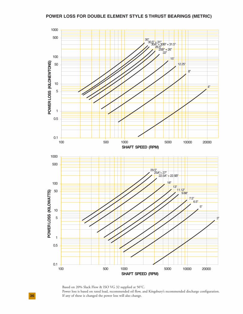
POWER LOSS FOR DOUBLE ELEMENT STYLE S THRUST BEARINGS (METRIC)
PO
WE
RLO
SS
(KIL
OW
ATT
S)
0.1
1
0.5
5
10
50
1000
500
100
100 500 1000 5000 10000 20000SHAFT SPEED (RPM)
7.5"7.5"6.5"6.5"
5"5"
3"3"
9.88"9.88"11.12"11.12"
13"13"18"18"
22.5A"+22.5B"22.5A" + 22.5B"25A"+27"25A"+ 27"
29.529.5
7.5"6.5"
5"
3"
9.88"11.12"
13"18"
22.5A"+22.5B"25A"+27"
29.5"
Based on 20% Slack Flow & ISO VG 32 supplied at 50˚C.Power loss is based on rated load, recommended oil flow, and Kingsbury’s recommended discharge configuration.If any of these is changed the power loss will also change.
PO
WE
RLO
SS
(KIL
ON
EW
TON
S)
0.1
1
0.5
5
10
50
1000
500
100
100 500 1000 5000 10000 20000SHAFT SPEED (RPM)
4"4"
12.25"12.25"
15"15"
22"22"
26.5"26.5"25B"+26"25B" + 26"
8"8"
30.5"+31"30.5" + 31"30A"+30B"+31.5"30A" + 30B" + 31.5"
35"35"
4"
12.25"
15"
22"
26.5"25B"+26"
8"
30.5"+31"30A"+30B"+31.5"
35"
37
SBEARINGS,
METRIC
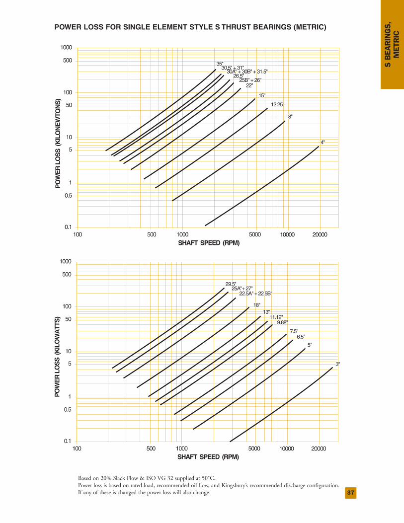
POWER LOSS FOR SINGLE ELEMENT STYLE S THRUST BEARINGS (METRIC)
PO
WE
RLO
SS
(KIL
ON
EW
TON
S)
0.1
1
0.5
5
10
50
1000
500
100
100 500 1000 5000 10000 20000SHAFT SPEED (RPM)
4"4"
12.25"12.25"
15"15"
22"22"
26.5"26.5"25B"+26"25B" + 26"
8"8"
30.5"+31"30.5" + 31"30A"+30B"+31.5"30A" + 30B" + 31.5"
35"35"
4"
12.25"
15"
22"
26.5"25B"+26"
8"
30.5"+31"30A"+30B"+31.5"
35"P
OW
ER
LOS
S(K
ILO
WA
TTS
)
0.1
1
0.5
5
10
50
1000
500
100
100 500 1000 5000 10000 20000SHAFT SPEED (RPM)
7.5"7.5"6.5"6.5"
5"5"
3"3"
9.88"9.88"11.12"11.12"
13"13"18"18"
22.5A"+22.5B"22.5A" + 22.5B"25A"+27"25A"+ 27"
29.529.5
7.5"6.5"
5"
3"
9.88"11.12"
13"18"
22.5A"+22.5B"25A"+27"
29.5"
Based on 20% Slack Flow & ISO VG 32 supplied at 50˚C.Power loss is based on rated load, recommended oil flow, and Kingsbury’s recommended discharge configuration.If any of these is changed the power loss will also change.
38
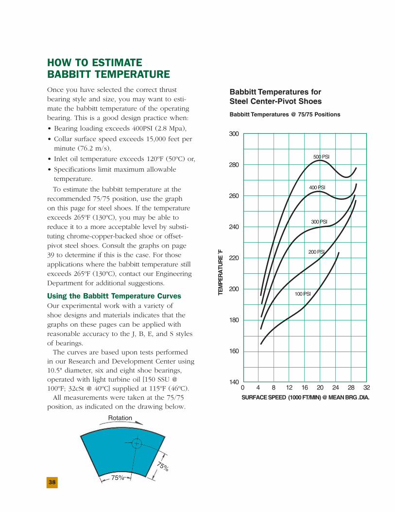
HOW TO ESTIMATEBABBITT TEMPERATUREOnce you have selected the correct thrustbearing style and size, you may want to esti-mate the babbitt temperature of the operatingbearing. This is a good design practice when:
• Bearing loading exceeds 400PSI (2.8 Mpa),
• Collar surface speed exceeds 15,000 feet perminute (76.2 m/s),
• Inlet oil temperature exceeds 120ºF (50ºC) or,
• Specifications limit maximum allowabletemperature.
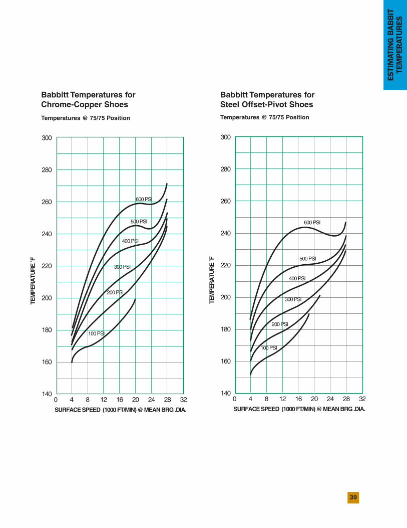
To estimate the babbitt temperature at therecommended 75/75 position, use the graphon this page for steel shoes. If the temperatureexceeds 265ºF (130ºC), you may be able toreduce it to a more acceptable level by substi-tuting chrome-copper-backed shoe or offset-pivot steel shoes. Consult the graphs on page39 to determine if this is the case. For thoseapplications where the babbitt temperature stillexceeds 265ºF (130ºC), contact our EngineeringDepartment for additional suggestions.
Using the Babbitt Temperature CurvesOur experimental work with a variety ofshoe designs and materials indicates that thegraphs on these pages can be applied withreasonable accuracy to the J, B, E, and S stylesof bearings.The curves are based upon tests performed
in our Research and Development Center using10.5" diameter, six and eight shoe bearings,operated with light turbine oil [150 SSU @100ºF; 32cSt @ 40ºC] supplied at 115ºF (46ºC).All measurements were taken at the 75/75
position, as indicated on the drawing below.
Babbitt Temperatures forSteel Center-Pivot Shoes
Babbitt Temperatures @ 75/75 Positions
TEM
PE
RA
TUR
E˚F
300
280
260
240
220
200
180
160
1400 4 8 12 16 20 24 28 32
SURFACESPEED (1000FT/MIN)@MEANBRG.DIA.
100PSI
200PSI
300PSI
400PSI
500PSI
Rotation
75%
75%
39
ESTIMATINGBABBIT
TEMPERATURES
Babbitt Temperatures forChrome-Copper Shoes
Babbitt Temperatures forSteel Offset-Pivot Shoes
Temperatures @ 75/75 Position Temperatures @ 75/75 Position
TEM
PE
RA
TUR
E˚F
300
280
260
240
220
200
180
160
1400 4 8 12 16 20 24 28 32
SURFACESPEED (1000FT/MIN)@MEANBRG.DIA.
100PSI
200PSI
300PSI
400PSI
500PSI
600PSI
TEM
PE
RA
TUR
E˚F
300
280
260
240
220
200
180
160
1400 4 8 12 16 20 24 28 32
SURFACESPEED (1000FT/MIN)@MEANBRG.DIA.
100PSI
200PSI
300PSI
400PSI
500PSI
600PSI
40
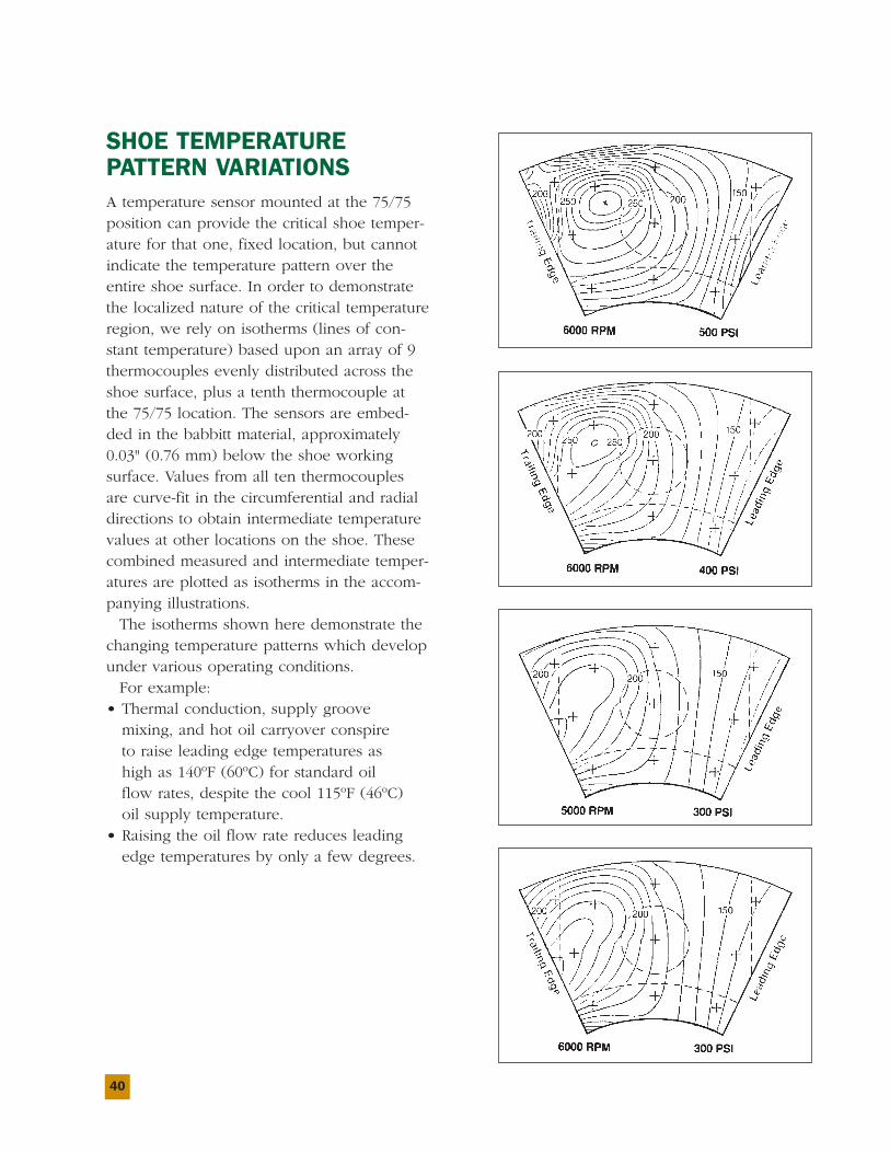
SHOE TEMPERATUREPATTERN VARIATIONSA temperature sensor mounted at the 75/75position can provide the critical shoe temper-ature for that one, fixed location, but cannotindicate the temperature pattern over theentire shoe surface. In order to demonstratethe localized nature of the critical temperatureregion, we rely on isotherms (lines of con-stant temperature) based upon an array of 9thermocouples evenly distributed across theshoe surface, plus a tenth thermocouple atthe 75/75 location. The sensors are embed-ded in the babbitt material, approximately0.03" (0.76 mm) below the shoe workingsurface. Values from all ten thermocouplesare curve-fit in the circumferential and radialdirections to obtain intermediate temperaturevalues at other locations on the shoe. Thesecombined measured and intermediate temper-atures are plotted as isotherms in the accom-panying illustrations.The isotherms shown here demonstrate the
changing temperature patterns which developunder various operating conditions.For example:
• Thermal conduction, supply groovemixing, and hot oil carryover conspireto raise leading edge temperatures ashigh as 140ºF (60ºC) for standard oilflow rates, despite the cool 115ºF (46ºC)oil supply temperature.
• Raising the oil flow rate reduces leadingedge temperatures by only a few degrees.
41
ESTIMATINGBABBIT
TEMPERATURES
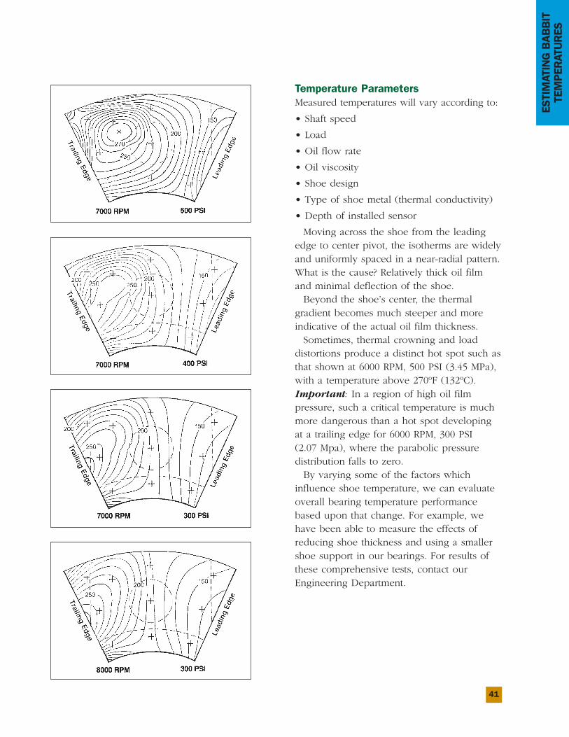
Temperature ParametersMeasured temperatures will vary according to:
• Shaft speed
• Load
• Oil flow rate
• Oil viscosity
• Shoe design
• Type of shoe metal (thermal conductivity)
• Depth of installed sensor
Moving across the shoe from the leadingedge to center pivot, the isotherms are widelyand uniformly spaced in a near-radial pattern.What is the cause? Relatively thick oil filmand minimal deflection of the shoe.Beyond the shoe’s center, the thermal
gradient becomes much steeper and moreindicative of the actual oil film thickness.Sometimes, thermal crowning and load
distortions produce a distinct hot spot such asthat shown at 6000 RPM, 500 PSI (3.45 MPa),with a temperature above 270ºF (132ºC).Important: In a region of high oil filmpressure, such a critical temperature is muchmore dangerous than a hot spot developingat a trailing edge for 6000 RPM, 300 PSI(2.07 Mpa), where the parabolic pressuredistribution falls to zero.By varying some of the factors which
influence shoe temperature, we can evaluateoverall bearing temperature performancebased upon that change. For example, wehave been able to measure the effects ofreducing shoe thickness and using a smallershoe support in our bearings. For results ofthese comprehensive tests, contact ourEngineering Department.
42
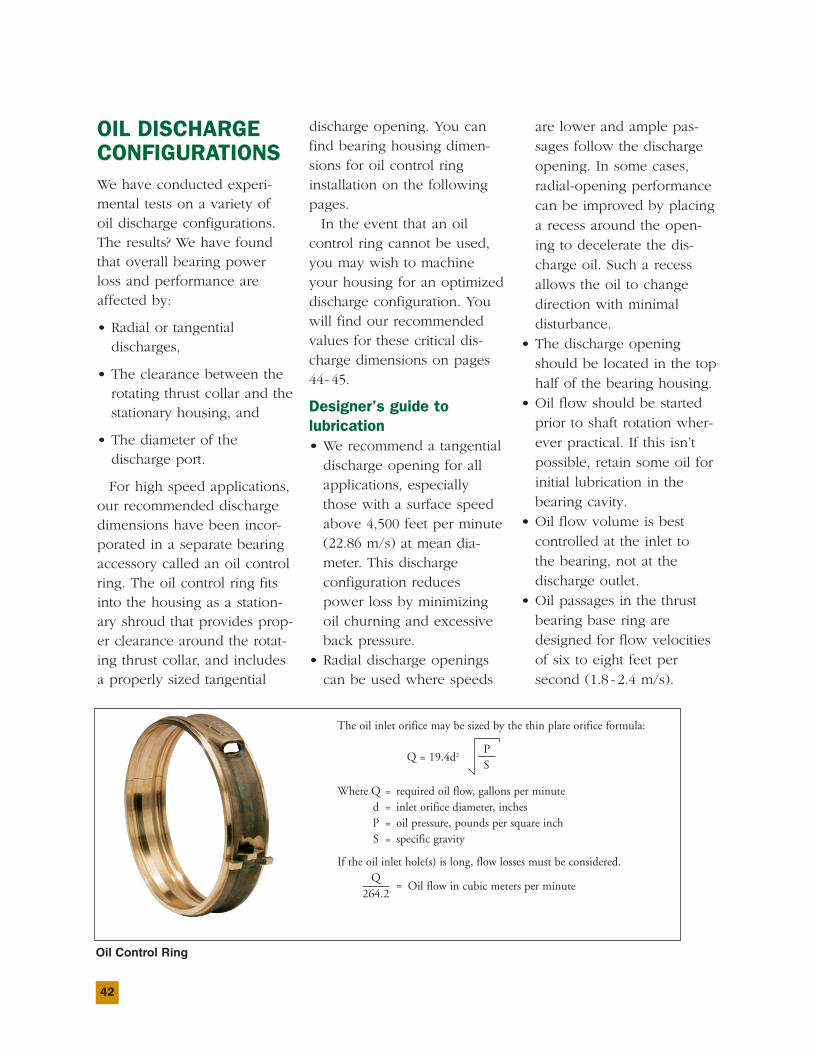
OIL DISCHARGECONFIGURATIONSWe have conducted experi-mental tests on a variety ofoil discharge configurations.The results? We have foundthat overall bearing powerloss and performance areaffected by:
• Radial or tangentialdischarges,
• The clearance between therotating thrust collar and thestationary housing, and
• The diameter of thedischarge port.
For high speed applications,our recommended dischargedimensions have been incor-porated in a separate bearingaccessory called an oil controlring. The oil control ring fitsinto the housing as a station-ary shroud that provides prop-er clearance around the rotat-ing thrust collar, and includesa properly sized tangential
discharge opening. You canfind bearing housing dimen-sions for oil control ringinstallation on the followingpages.In the event that an oil
control ring cannot be used,you may wish to machineyour housing for an optimizeddischarge configuration. Youwill find our recommendedvalues for these critical dis-charge dimensions on pages44- 45.
Designer’s guide tolubrication• We recommend a tangentialdischarge opening for allapplications, especiallythose with a surface speedabove 4,500 feet per minute(22.86 m/s) at mean dia-meter. This dischargeconfiguration reducespower loss by minimizingoil churning and excessiveback pressure.
• Radial discharge openingscan be used where speeds
are lower and ample pas-sages follow the dischargeopening. In some cases,radial-opening performancecan be improved by placinga recess around the open-ing to decelerate the dis-charge oil. Such a recessallows the oil to changedirection with minimaldisturbance.
• The discharge openingshould be located in the tophalf of the bearing housing.
• Oil flow should be startedprior to shaft rotation wher-ever practical. If this isn’tpossible, retain some oil forinitial lubrication in thebearing cavity.
• Oil flow volume is bestcontrolled at the inlet tothe bearing, not at thedischarge outlet.
• Oil passages in the thrustbearing base ring aredesigned for flow velocitiesof six to eight feet persecond (1.8 - 2.4 m/s).
The oil inlet orifice may be sized by the thin plate orifice formula:
PQ = 19.4d2
S
Where Q = required oil flow, gallons per minuted = inlet orifice diameter, inchesP = oil pressure, pounds per square inchS = specific gravity
If the oil inlet hole(s) is long, flow losses must be considered.Q
264.2= Oil flow in cubic meters per minute
Oil Control Ring
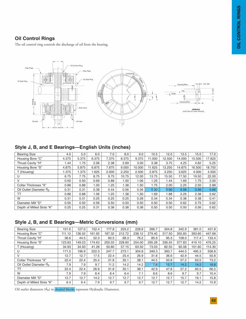
43
OILCONTROLRINGS
Oil Control RingsThe oil control ring controls the discharge of oil from the bearing.
Style J, B, and E Bearings—Metric Conversions (mm)
Style J, B, and E Bearings—English Units (inches)
D Dia. MillC
Housing Bore
TT
Housing BoreS W
VIEW C-CJoint Face of Lower Housing
UDia.
T/2
CLCollar
v
KC C
d 0
T
CH
ousi
ngB
ore
HH X
Oil Inlet
Shim Pack
Oil Inlet
Oil Control Ring
Filler Plate
Oil Seal Ring
Filler Plate
Oil Seal Ring
Rotation
Bearing Size 4.0 5.0 6.0 7.0 8.0 9.0 10.5 12.0 13.5 15.0 17.0Housing Bore “C” 4.375 5.375 6.375 7.375 8.375 9.375 11.000 12.500 14.000 15.500 17.625Thrust Cavity “H” 1.44 1.75 2.06 2.38 2.69 3.00 3.38 3.75 4.25 4.62 5.25Housing Bore “S” 4.875 5.875 6.875 7.875 9.000 10.000 11.625 13.250 14.875 16.500 18.750T (Housing) 1.375 1.375 1.625 2.000 2.250 2.500 2.875 3.250 3.625 4.000 4.500U 6.75 7.75 8.75 9.75 10.75 12.00 13.75 15.50 17.50 19.50 22.00V 0.50 0.50 0.69 0.88 1.00 1.06 1.25 1.44 1.69 1.75 2.00Collar Thickness “X” 0.88 0.88 1.00 1.25 1.38 1.50 1.75 2.00 2.25 2.50 2.88Oil Outlet Diameter do 0.31 0.31 0.38 0.44 0.56 0.56 0.30 0.50 0.56 0.56 0.66TT 0.88 0.88 1.06 1.25 1.38 1.50 1.69 1.88 2.25 2.38 2.62W 0.31 0.31 0.25 0.25 0.25 0.28 0.34 0.34 0.38 0.38 0.41Diameter Mill “D” 0.50 0.50 0.56 0.50 0.50 0.50 0.50 0.50 0.62 0.75 0.62Depth of Milled Slots “K” 0.25 0.25 0.31 0.38 0.38 0.38 0.50 0.50 0.50 0.56 0.62
Bearing Size 101.6 127.0 152.4 177.8 203.2 228.6 266.7 304.8 342.9 381.0 431.8Housing Bore “C” 111.12 136.52 161.92 187.32 212.72 238.12 279.40 317.50 355.60 393.60 447.68Thrust Cavity “H” 36.6 44.5 52.3 60.5 68.3 76.2 85.9 95.3 108.0 117.4 133.4Housing Bore “S” 123.83 149.23 174.63 200.03 228.60 254.00 295.28 336.55 377.83 419.10 476.25T (Housing) 34.93 34.93 41.28 50.80 57.15 63.50 73.03 82.55 92.08 101.60 114.30U 171.5 196.9 222.3 247.7 273.1 304.8 349.3 393.7 444.5 495.3 558.8V 12.7 12.7 17.5 22.4 25.4 26.9 31.8 36.6 42.9 44.5 50.8Collar Thickness “X” 22.4 22.4 25.4 31.8 35.1 38.1 44.5 50.8 57.2 63.5 73.2Oil Outlet Diameter do 7.9 7.9 9.7 11.2 14.2 14.2 7.6 12.7 14.2 14.2 16.8TT 22.4 22.4 26.9 31.8 35.1 38.1 42.9 47.8 57.2 60.5 66.5W 7.9 7.9 6.4 6.4 6.4 7.1 8.6 8.6 9.7 9.7 10.4Diameter Mill “D” 12.7 12.7 14.2 12.7 12.7 12.7 12.7 12.7 15.7 19.1 15.8Depth of Milled Slots “K” 6.4 6.4 7.9 9.7 9.7 9.7 12.7 12.7 12.7 14.2 15.8
Oil outlet diameters (do) in shaded blocks represent Hydraulic Diameters.
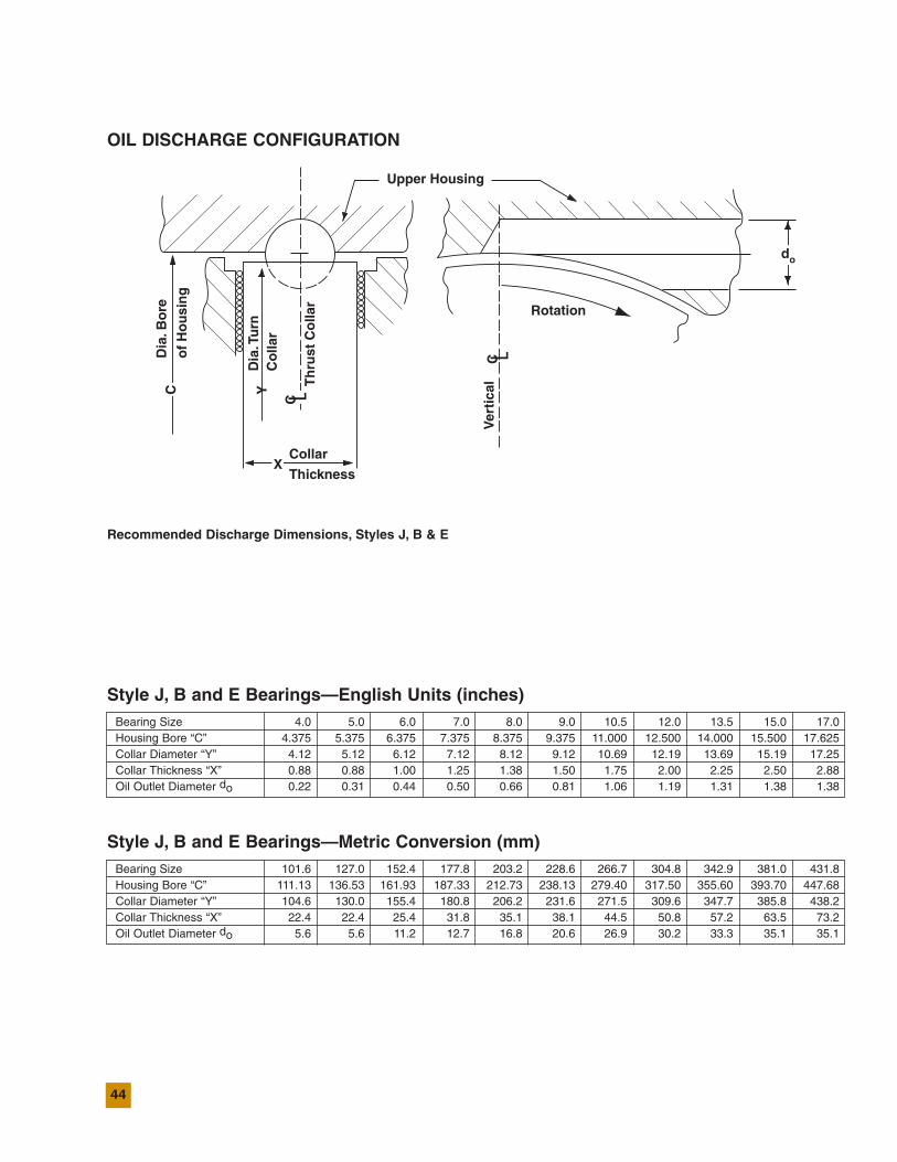
44
OIL DISCHARGE CONFIGURATION
Recommended Discharge Dimensions, Styles J, B & E
Style J, B and E Bearings—Metric Conversion (mm)Bearing Size 101.6 127.0 152.4 177.8 203.2 228.6 266.7 304.8 342.9 381.0 431.8Housing Bore “C” 111.13 136.53 161.93 187.33 212.73 238.13 279.40 317.50 355.60 393.70 447.68Collar Diameter “Y” 104.6 130.0 155.4 180.8 206.2 231.6 271.5 309.6 347.7 385.8 438.2Collar Thickness “X” 22.4 22.4 25.4 31.8 35.1 38.1 44.5 50.8 57.2 63.5 73.2Oil Outlet Diameter do 5.6 5.6 11.2 12.7 16.8 20.6 26.9 30.2 33.3 35.1 35.1
Style J, B and E Bearings—English Units (inches)Bearing Size 4.0 5.0 6.0 7.0 8.0 9.0 10.5 12.0 13.5 15.0 17.0Housing Bore “C” 4.375 5.375 6.375 7.375 8.375 9.375 11.000 12.500 14.000 15.500 17.625Collar Diameter “Y” 4.12 5.12 6.12 7.12 8.12 9.12 10.69 12.19 13.69 15.19 17.25Collar Thickness “X” 0.88 0.88 1.00 1.25 1.38 1.50 1.75 2.00 2.25 2.50 2.88Oil Outlet Diameter do 0.22 0.31 0.44 0.50 0.66 0.81 1.06 1.19 1.31 1.38 1.38
Upper Housing
Rotation
Collar
ThicknessV
erti
calTh
rust
Co
llar
Dia
.Tu
rnC
olla
r
Dia
.Bo
re
of
Ho
usi
ng
X
YC
C
C
do
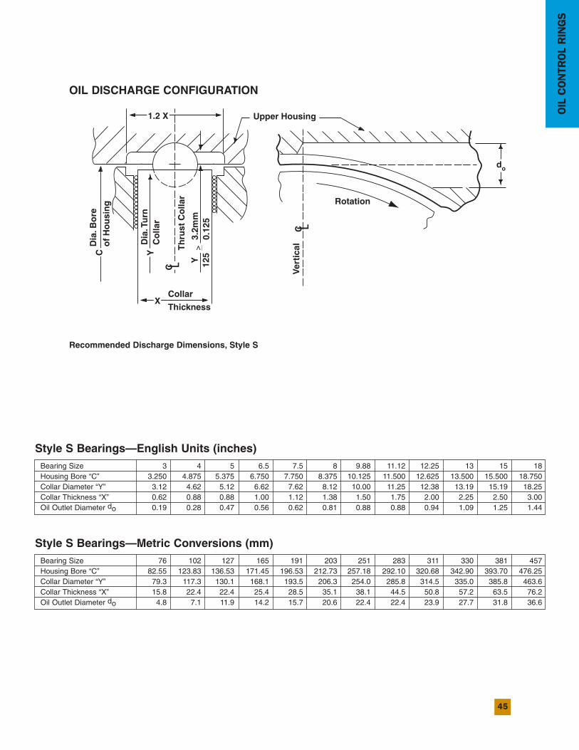
45
OILCONTROLRINGS
Recommended Discharge Dimensions, Style S
Style S Bearings—English Units (inches)Bearing Size 3 4 5 6.5 7.5 8 9.88 11.12 12.25 13 15 18Housing Bore “C” 3.250 4.875 5.375 6.750 7.750 8.375 10.125 11.500 12.625 13.500 15.500 18.750Collar Diameter “Y” 3.12 4.62 5.12 6.62 7.62 8.12 10.00 11.25 12.38 13.19 15.19 18.25Collar Thickness “X” 0.62 0.88 0.88 1.00 1.12 1.38 1.50 1.75 2.00 2.25 2.50 3.00Oil Outlet Diameter do 0.19 0.28 0.47 0.56 0.62 0.81 0.88 0.88 0.94 1.09 1.25 1.44
Style S Bearings—Metric Conversions (mm)Bearing Size 76 102 127 165 191 203 251 283 311 330 381 457Housing Bore “C” 82.55 123.83 136.53 171.45 196.53 212.73 257.18 292.10 320.68 342.90 393.70 476.25Collar Diameter “Y” 79.3 117.3 130.1 168.1 193.5 206.3 254.0 285.8 314.5 335.0 385.8 463.6Collar Thickness “X” 15.8 22.4 22.4 25.4 28.5 35.1 38.1 44.5 50.8 57.2 63.5 76.2Oil Outlet Diameter do 4.8 7.1 11.9 14.2 15.7 20.6 22.4 22.4 23.9 27.7 31.8 36.6
Upper Housing
Rotation
Collar
ThicknessV
erti
calTh
rust
Co
llar
Dia
.Tu
rnC
olla
r
Dia
.Bo
re
of
Ho
usi
ng
1.2 X
X
Y
3.2m
m0.
125
Y 125C
C
C
do
OIL DISCHARGE CONFIGURATION
>
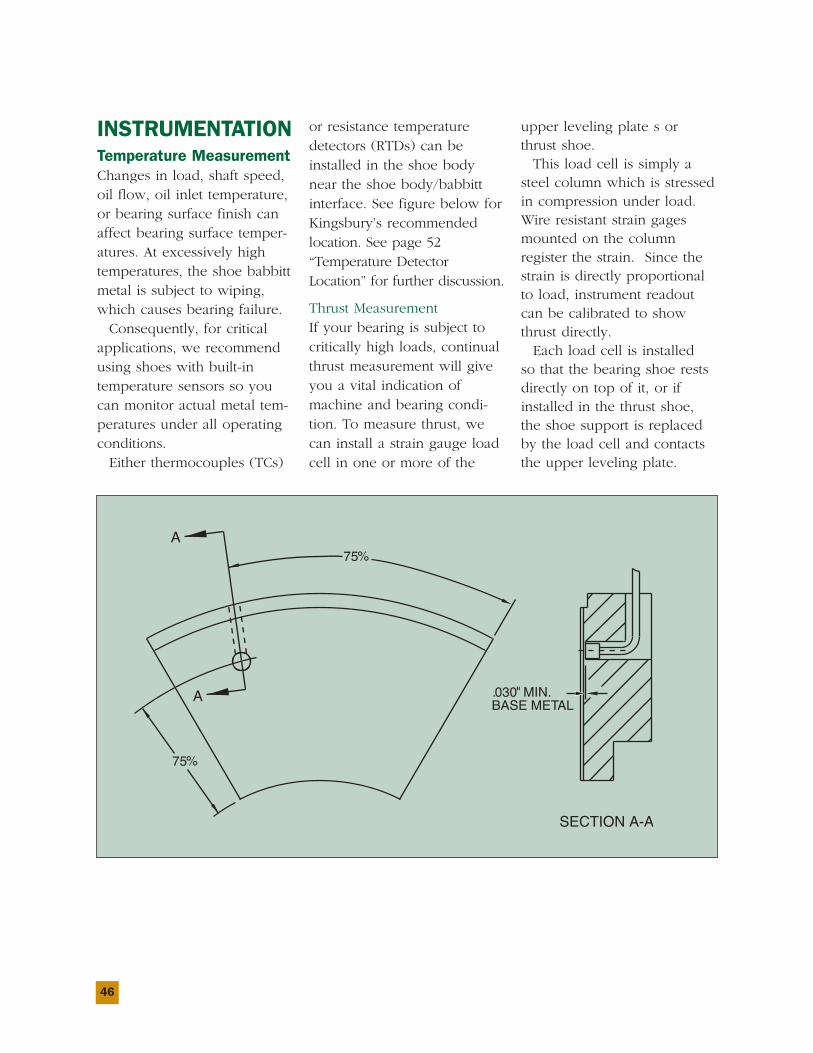
46
INSTRUMENTATIONTemperature MeasurementChanges in load, shaft speed,oil flow, oil inlet temperature,or bearing surface finish canaffect bearing surface temper-atures. At excessively hightemperatures, the shoe babbittmetal is subject to wiping,which causes bearing failure.Consequently, for critical
applications, we recommendusing shoes with built-intemperature sensors so youcan monitor actual metal tem-peratures under all operatingconditions.Either thermocouples (TCs)
or resistance temperaturedetectors (RTDs) can beinstalled in the shoe bodynear the shoe body/babbittinterface. See figure below forKingsbury’s recommendedlocation. See page 52“Temperature DetectorLocation” for further discussion.
Thrust MeasurementIf your bearing is subject tocritically high loads, continualthrust measurement will giveyou a vital indication ofmachine and bearing condi-tion. To measure thrust, wecan install a strain gauge loadcell in one or more of the
upper leveling plate s orthrust shoe.This load cell is simply a
steel column which is stressedin compression under load.Wire resistant strain gagesmounted on the columnregister the strain. Since thestrain is directly proportionalto load, instrument readoutcan be calibrated to showthrust directly.Each load cell is installed
so that the bearing shoe restsdirectly on top of it, or ifinstalled in the thrust shoe,the shoe support is replacedby the load cell and contactsthe upper leveling plate.
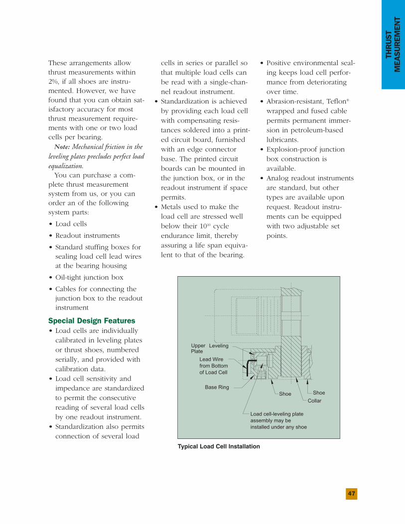
47
THRUST
MEASUREM
ENT
These arrangements allowthrust measurements within2%, if all shoes are instru-mented. However, we havefound that you can obtain sat-isfactory accuracy for mostthrust measurement require-ments with one or two loadcells per bearing.
Note: Mechanical friction in theleveling plates precludes perfect loadequalization.You can purchase a com-
plete thrust measurementsystem from us, or you canorder an of the followingsystem parts:
• Load cells
• Readout instruments
• Standard stuffing boxes forsealing load cell lead wiresat the bearing housing
• Oil-tight junction box
• Cables for connecting thejunction box to the readoutinstrument
Special Design Features• Load cells are individuallycalibrated in leveling platesor thrust shoes, numberedserially, and provided withcalibration data.
• Load cell sensitivity andimpedance are standardizedto permit the consecutivereading of several load cellsby one readout instrument.
• Standardization also permitsconnection of several load
cells in series or parallel sothat multiple load cells canbe read with a single-chan-nel readout instrument.
• Standardization is achievedby providing each load cellwith compensating resis-tances soldered into a print-ed circuit board, furnishedwith an edge connectorbase. The printed circuitboards can be mounted inthe junction box, or in thereadout instrument if spacepermits.
• Metals used to make theload cell are stressed wellbelow their 1010 cycleendurance limit, therebyassuring a life span equiva-lent to that of the bearing.
• Positive environmental seal-ing keeps load cell perfor-mance from deterioratingover time.
• Abrasion-resistant, Teflon®
wrapped and fused cablepermits permanent immer-sion in petroleum-basedlubricants.
• Explosion-proof junctionbox construction isavailable.
• Analog readout instrumentsare standard, but othertypes are available uponrequest. Readout instru-ments can be equippedwith two adjustable setpoints.
Base Ring
Upper LevelingPlate
Shoe ShoeCollar
Load cell-leveling plateassembly may beinstalled under any shoe
Lead Wirefrom Bottomof Load Cell
Typical Load Cell Installation
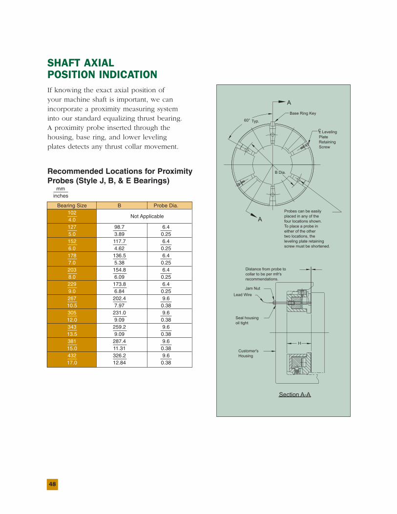
48
SHAFT AXIALPOSITION INDICATIONIf knowing the exact axial position ofyour machine shaft is important, we canincorporate a proximity measuring systeminto our standard equalizing thrust bearing.A proximity probe inserted through thehousing, base ring, and lower levelingplates detects any thrust collar movement.
Recommended Locations for ProximityProbes (Style J, B, & E Bearings)
mminches
Bearing Size B Probe Dia.102
Not Applicable4.0127 98.7 6.45.0 3.89 0.25152 117.7 6.46.0 4.62 0.25178 136.5 6.47.0 5.38 0.25203 154.8 6.48.0 6.09 0.25229 173.8 6.49.0 6.84 0.25267 202.4 9.610.5 7.97 0.38305 231.0 9.612.0 9.09 0.38343 259.2 9.613.5 9.09 0.38381 287.4 9.615.0 11.31 0.38432 326.2 9.617.0 12.84 0.38
B Dia.
60° Typ.
A
Section A-A
A
Base Ring Key
CL LevelingPlateRetainingScrew
Probes can be easilyplaced in any of thefour locations shown.To place a probe ineither of the othertwo locations, theleveling plate retainingscrew must be shortened.
Distance from probe tocollar to be per mfr'srecommendations.
Jam NutLead Wire
Seal housingoil tight
H
Customer'sHousing
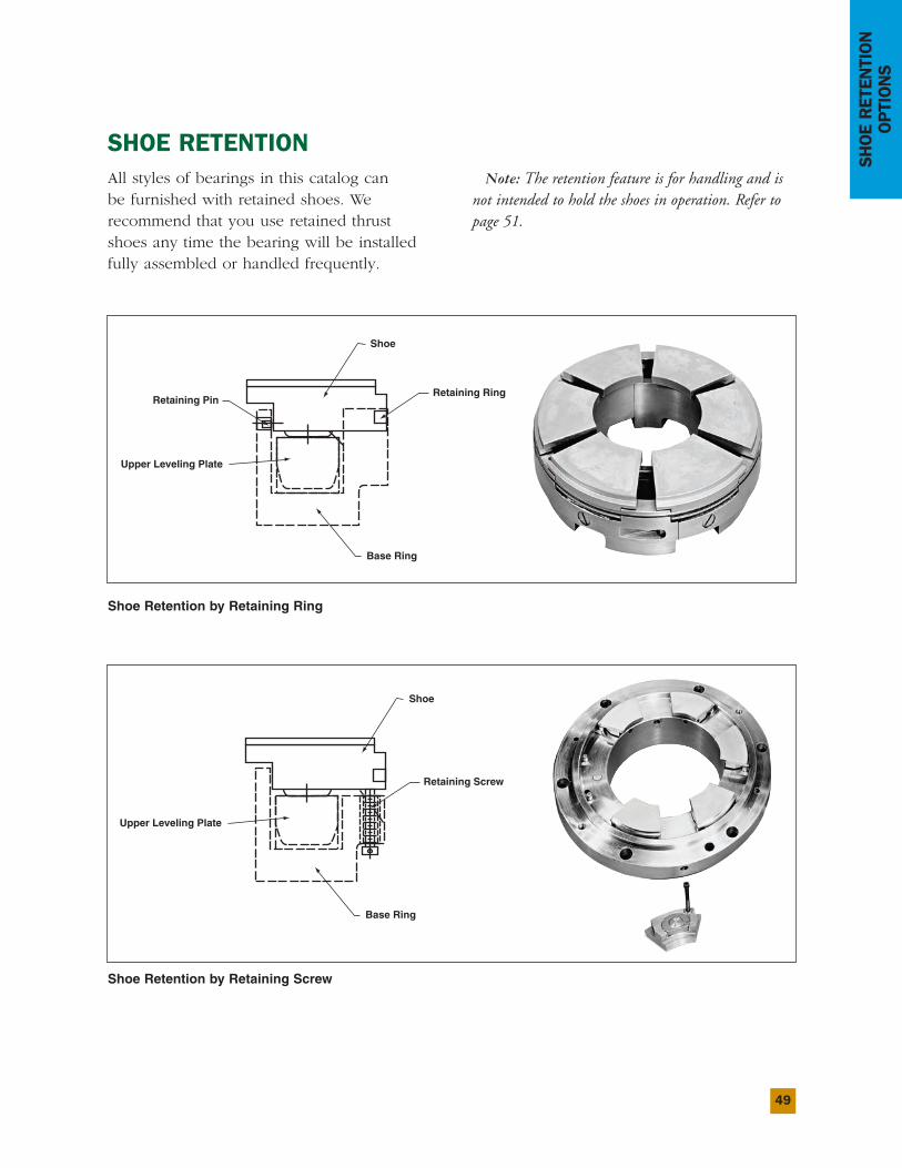
49
SHOERETENTION
OPTIONS
SHOE RETENTIONAll styles of bearings in this catalog canbe furnished with retained shoes. Werecommend that you use retained thrustshoes any time the bearing will be installedfully assembled or handled frequently.
Shoe Retention by Retaining Ring
Shoe Retention by Retaining Screw
Retaining Pin
Shoe
Retaining Ring
Base Ring
Upper Leveling Plate
Note: The retention feature is for handling and isnot intended to hold the shoes in operation. Refer topage 51.
Shoe
Retaining Screw
Base Ring
Upper Leveling Plate
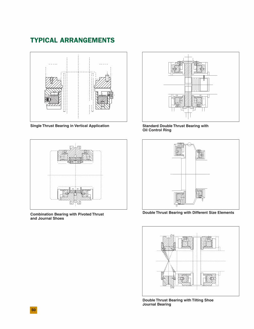
50
TYPICAL ARRANGEMENTS
Single Thrust Bearing in Vertical Application
Combination Bearing with Pivoted Thrustand Journal Shoes
Standard Double Thrust Bearing withOil Control Ring
Double Thrust Bearing with Different Size Elements
Double Thrust Bearing with Tilting ShoeJournal Bearing
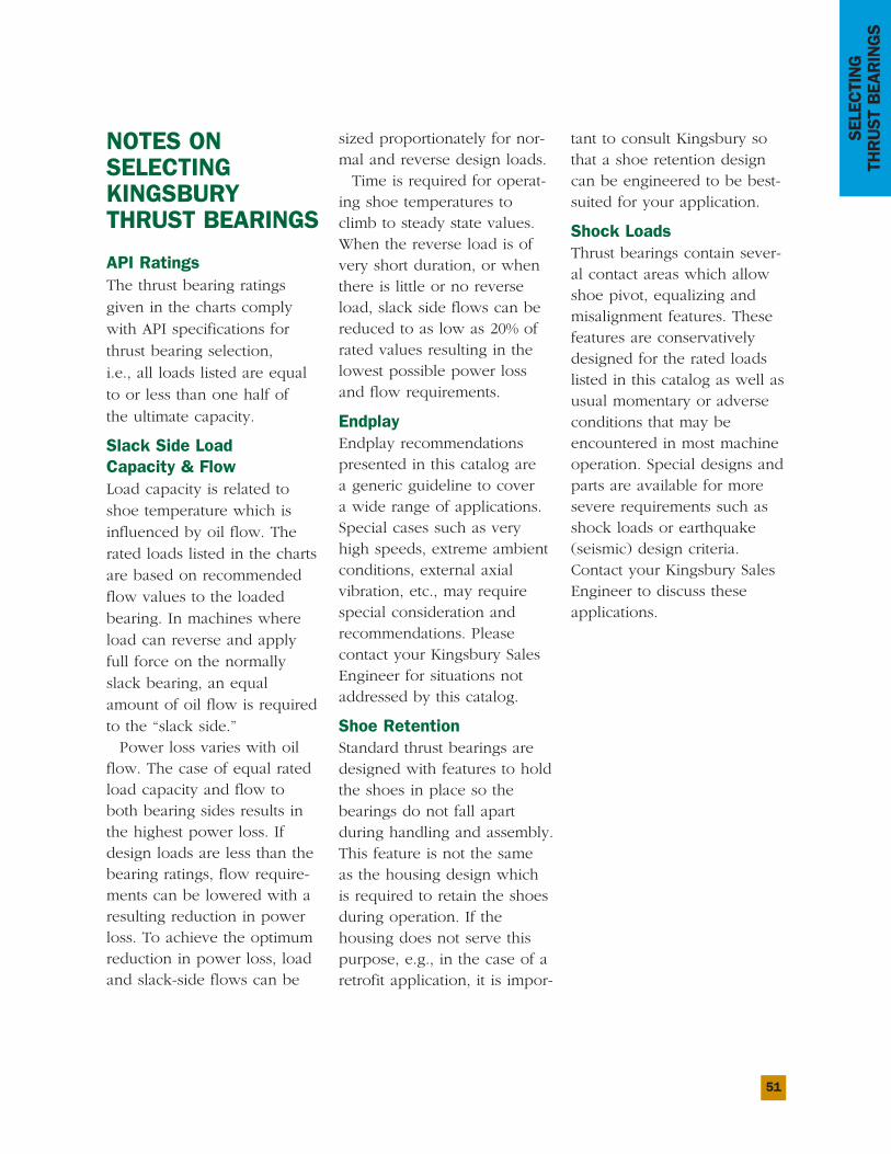
51
SELECTING
THRUSTBEARINGS
NOTES ONSELECTINGKINGSBURYTHRUST BEARINGS
API RatingsThe thrust bearing ratingsgiven in the charts complywith API specifications forthrust bearing selection,i.e., all loads listed are equalto or less than one half ofthe ultimate capacity.
Slack Side LoadCapacity & FlowLoad capacity is related toshoe temperature which isinfluenced by oil flow. Therated loads listed in the chartsare based on recommendedflow values to the loadedbearing. In machines whereload can reverse and applyfull force on the normallyslack bearing, an equalamount of oil flow is requiredto the “slack side.”Power loss varies with oil
flow. The case of equal ratedload capacity and flow toboth bearing sides results inthe highest power loss. Ifdesign loads are less than thebearing ratings, flow require-ments can be lowered with aresulting reduction in powerloss. To achieve the optimumreduction in power loss, loadand slack-side flows can be
sized proportionately for nor-mal and reverse design loads.Time is required for operat-
ing shoe temperatures toclimb to steady state values.When the reverse load is ofvery short duration, or whenthere is little or no reverseload, slack side flows can bereduced to as low as 20% ofrated values resulting in thelowest possible power lossand flow requirements.
EndplayEndplay recommendationspresented in this catalog area generic guideline to covera wide range of applications.Special cases such as veryhigh speeds, extreme ambientconditions, external axialvibration, etc., may requirespecial consideration andrecommendations. Pleasecontact your Kingsbury SalesEngineer for situations notaddressed by this catalog.
Shoe RetentionStandard thrust bearings aredesigned with features to holdthe shoes in place so thebearings do not fall apartduring handling and assembly.This feature is not the sameas the housing design whichis required to retain the shoesduring operation. If thehousing does not serve thispurpose, e.g., in the case of aretrofit application, it is impor-
tant to consult Kingsbury sothat a shoe retention designcan be engineered to be best-suited for your application.
Shock LoadsThrust bearings contain sever-al contact areas which allowshoe pivot, equalizing andmisalignment features. Thesefeatures are conservativelydesigned for the rated loadslisted in this catalog as well asusual momentary or adverseconditions that may beencountered in most machineoperation. Special designs andparts are available for moresevere requirements such asshock loads or earthquake(seismic) design criteria.Contact your Kingsbury SalesEngineer to discuss theseapplications.
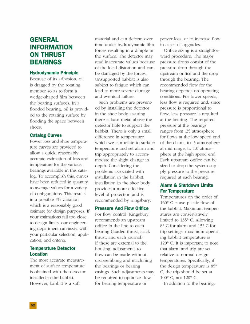
52
GENERALINFORMATIONON THRUSTBEARINGS
Hydrodynamic PrincipleBecause of its adhesion, oilis dragged by the rotatingmember so as to form awedge-shaped film betweenthe bearing surfaces. In aflooded bearing, oil is provid-ed to the rotating surface byflooding the space betweenshoes.
Catalog CurvesPower loss and shoe tempera-ture curves are provided toallow a quick, reasonablyaccurate estimation of loss andtemperature for the variousbearings available in this cata-log. To accomplish this, curveshave been reduced in quantityto average values for a varietyof configurations. This resultsin a possible 5% variationwhich is a reasonably goodestimate for design purposes. Ifyour estimations fall too closeto design limits, our engineer-ing department can assist withyour particular selection, appli-cation, and criteria.
Temperature DetectorLocationThe most accurate measure-ment of surface temperatureis obtained with the detectorinstalled in the babbitt.However, babbitt is a soft
material and can deform overtime under hydrodynamic filmforces resulting in a dimple inthe surface. The detector mayread inaccurate values becauseof the local distortion and canbe damaged by the forces.Unsupported babbitt is alsosubject to fatigue which canlead to more severe damageand eventual failure.Such problems are prevent-
ed by installing the detectorin the shoe body assuringthere is base metal above thedetector hole to support thebabbitt. There is only a smalldifference in temperaturewhich we can relate to surfacetemperature and set alarm andtrip appropriately to accom-modate the slight change indepth. Considering theproblems associated withinstallation in the babbitt,installation in the shoe bodyprovides a more effectivelevel of protection and isrecommended by Kingsbury.
Pressure And Flow OrificeFor flow control, Kingsburyrecommends an upstreamorifice in the line to eachbearing (loaded thrust, slackthrust, and each journal).If these are external to thehousing, adjustments toflow can be made withoutdisassembling and machiningthe bearings or bearingcasings. Such adjustments maybe required to optimize flowfor bearing temperature or
power loss, or to increase flowin cases of upgrades.Orifice sizing is a straightfor-
ward procedure. The majorpressure drops consist of thepressure drop through theupstream orifice and the dropthrough the bearing. Therecommended flow for thebearing depends on operatingconditions. For lower speeds,less flow is required and, sincepressure is proportional toflow, less pressure is requiredat the bearing. The requiredpressure at the bearingsranges from .25 atmospherefor flows at the low speed endof the charts, to .5 atmosphereat mid range, to 1.0 atmos-phere at the high speed end.Each upstream orifice can besized to drop the system sup-ply pressure to the pressurerequired at each bearing.
Alarm & Shutdown LimitsFor TemperatureTemperatures on the order of160° C cause plastic flow ofthe babbitt. Maximum temper-atures are conservativelylimited to 135° C. Allowing8° C for alarm and 15° C fortrip settings, maximum operat-ing babbitt temperature is120° C. It is important to notethat alarm and trip are setrelative to normal designtemperatures. Specifically, ifthe design temperature is 85°C, the trip should be set at100° C, not 120° C.In addition to the bearing,
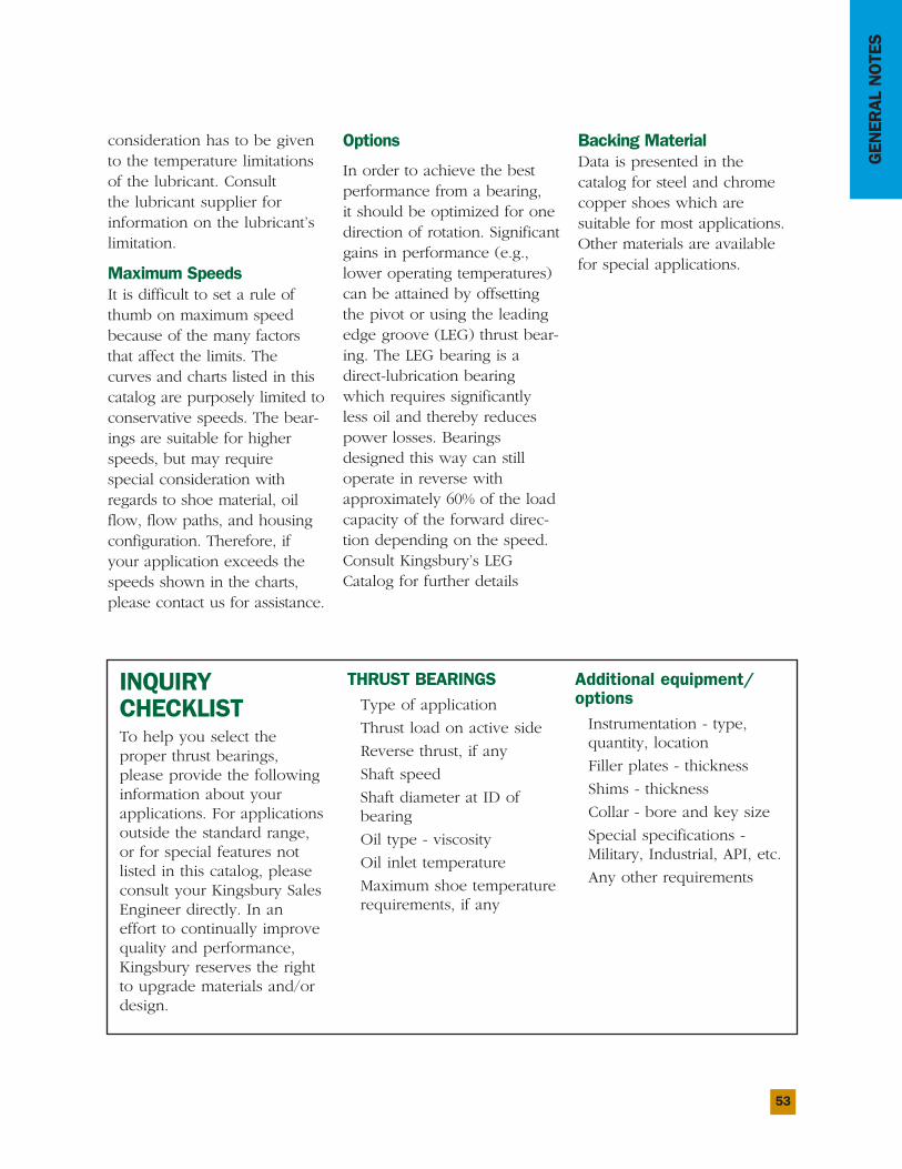
53
GENERALNOTES
consideration has to be givento the temperature limitationsof the lubricant. Consultthe lubricant supplier forinformation on the lubricant’slimitation.
Maximum SpeedsIt is difficult to set a rule ofthumb on maximum speedbecause of the many factorsthat affect the limits. Thecurves and charts listed in thiscatalog are purposely limited toconservative speeds. The bear-ings are suitable for higherspeeds, but may requirespecial consideration withregards to shoe material, oilflow, flow paths, and housingconfiguration. Therefore, ifyour application exceeds thespeeds shown in the charts,please contact us for assistance.
Options
In order to achieve the bestperformance from a bearing,it should be optimized for onedirection of rotation. Significantgains in performance (e.g.,lower operating temperatures)can be attained by offsettingthe pivot or using the leadingedge groove (LEG) thrust bear-ing. The LEG bearing is adirect-lubrication bearingwhich requires significantlyless oil and thereby reducespower losses. Bearingsdesigned this way can stilloperate in reverse withapproximately 60% of the loadcapacity of the forward direc-tion depending on the speed.Consult Kingsbury’s LEGCatalog for further details
Backing MaterialData is presented in thecatalog for steel and chromecopper shoes which aresuitable for most applications.Other materials are availablefor special applications.
INQUIRYCHECKLISTTo help you select theproper thrust bearings,please provide the followinginformation about yourapplications. For applicationsoutside the standard range,or for special features notlisted in this catalog, pleaseconsult your Kingsbury SalesEngineer directly. In aneffort to continually improvequality and performance,Kingsbury reserves the rightto upgrade materials and/ordesign.
THRUST BEARINGSType of application
Thrust load on active side
Reverse thrust, if any
Shaft speed
Shaft diameter at ID ofbearing
Oil type - viscosity
Oil inlet temperature
Maximum shoe temperaturerequirements, if any
Additional equipment/optionsInstrumentation - type,quantity, location
Filler plates - thickness
Shims - thickness
Collar - bore and key size
Special specifications -Military, Industrial, API, etc.
Any other requirements
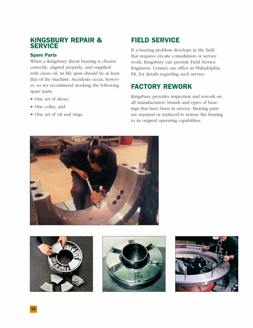
54
KINGSBURY REPAIR &SERVICESpare PartsWhen a Kingsbury thrust bearing is chosencorrectly, aligned properly, and suppliedwith clean oil, its life span should be at leastthat of the machine. Accidents occur, howev-er, so we recommend stocking the followingspare parts:
• One set of shoes,
• One collar, and
• One set of oil seal rings.
FIELD SERVICEIf a bearing problem develops in the fieldthat requires on-site consultation or servicework, Kingsbury can provide Field ServiceEngineers. Contact our office in Philadelphia,PA, for details regarding such service.
FACTORY REWORKKingsbury provides inspection and rework onall manufacturers’ brands and types of bear-ings that have been in service. Bearing partsare repaired or replaced to restore the bearingto its original operating capabilities.
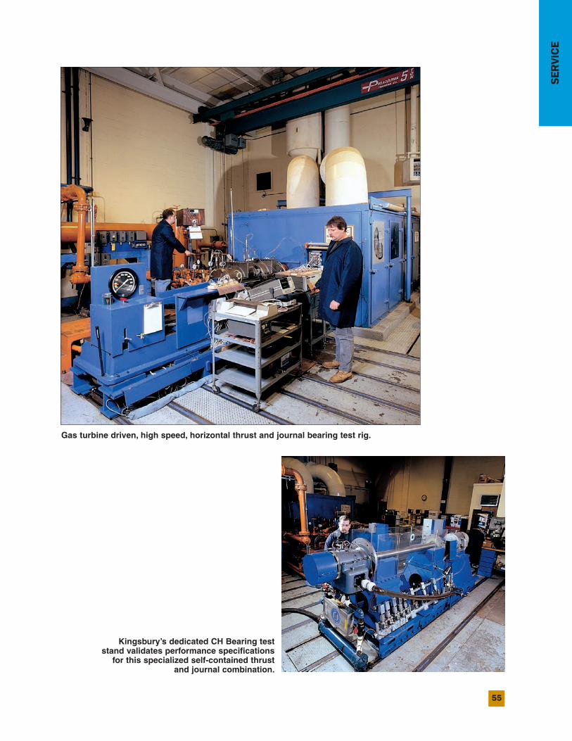
55
SERVICE
Gas turbine driven, high speed, horizontal thrust and journal bearing test rig.
Kingsbury’s dedicated CH Bearing teststand validates performance specificationsfor this specialized self-contained thrust
and journal combination.
10385 Drummond Road
Philadelphia, PA 19154 USA
Telephone: 1-215-824-4000
Fax: 1-215-824-4999
www.kingsbury.com
Catalog EQH-1Printed in USA 7/11
The Best Support InThe Business.