Embed Size (px)
Citation preview

Three-phase AC circuits
This worksheet and all related files are licensed under the Creative Commons Attribution License,version 1.0. To view a copy of this license, visit http://creativecommons.org/licenses/by/1.0/, or send aletter to Creative Commons, 559 Nathan Abbott Way, Stanford, California 94305, USA. The terms andconditions of this license allow for free copying, distribution, and/or modification of all licensed works bythe general public.
1
Questions
Question 1
AC electric generators (sometimes called alternators) work on the principle of electromagnetic induction,spinning a magnet between wire coils as such:
N S
iron
Mechanicaldiagram
Schematicdiagram
These wire coils typically exist in pairs opposite each other from the centerline of the rotor shaft. Thewire coils are called stator coils or stator windings, because they are stationary. This particular machine iscalled a single-phase alternator because the stator coils act as a single unit, producing one sine-wave ACvoltage as the magnetized rotor turns.
A three-phase AC generator has three sets of stator coils arranged 120o apart from each other aroundthe centerline of the rotor shaft:
A
A
B
B C
C
N S
Mechanicaldiagram Schematic
diagram
Since the three pairs of stator windings “see” the poles of the magnetized rotor pass by at differenttimes, their respective sine-wave voltages will be out of step (out of phase) with each other.
2
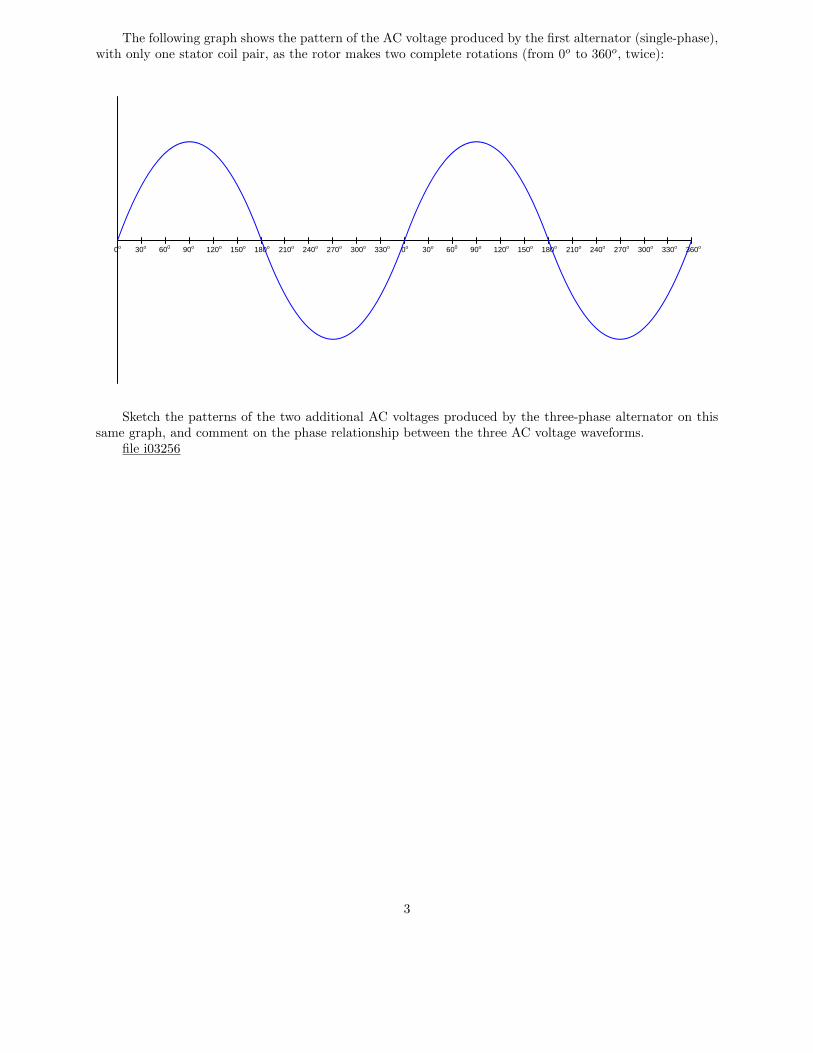
The following graph shows the pattern of the AC voltage produced by the first alternator (single-phase),with only one stator coil pair, as the rotor makes two complete rotations (from 0o to 360o, twice):
90o60030o 120o 150o 180o 210o 240o 270o 300o 330o0o 90o60030o 120o 150o 180o 210o 240o 270o 300o 330o 360o0o
Sketch the patterns of the two additional AC voltages produced by the three-phase alternator on thissame graph, and comment on the phase relationship between the three AC voltage waveforms.
file i03256
3
Question 2
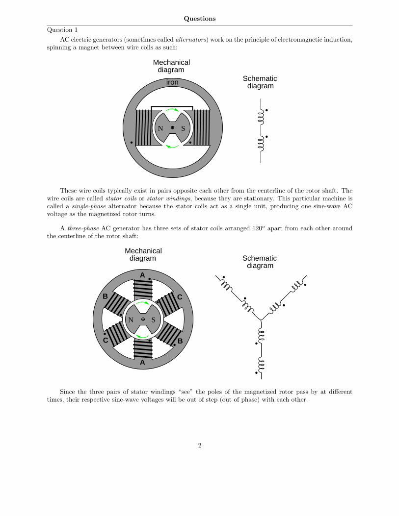
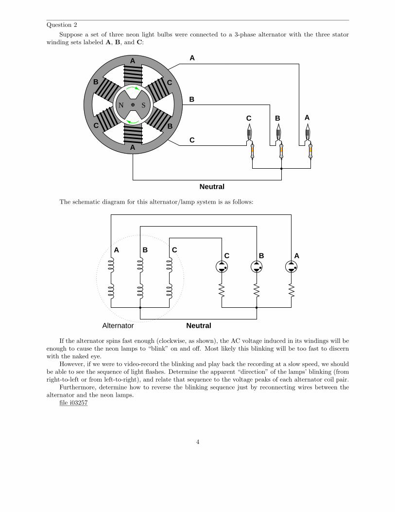
Suppose a set of three neon light bulbs were connected to a 3-phase alternator with the three statorwinding sets labeled A, B, and C:
A
A
B
B C
C
N S
A
B
C
ABC
Neutral
The schematic diagram for this alternator/lamp system is as follows:
Alternator
A B CB AC
Neutral
If the alternator spins fast enough (clockwise, as shown), the AC voltage induced in its windings will beenough to cause the neon lamps to “blink” on and off. Most likely this blinking will be too fast to discernwith the naked eye.
However, if we were to video-record the blinking and play back the recording at a slow speed, we shouldbe able to see the sequence of light flashes. Determine the apparent “direction” of the lamps’ blinking (fromright-to-left or from left-to-right), and relate that sequence to the voltage peaks of each alternator coil pair.
Furthermore, determine how to reverse the blinking sequence just by reconnecting wires between thealternator and the neon lamps.
file i03257
4
Question 3
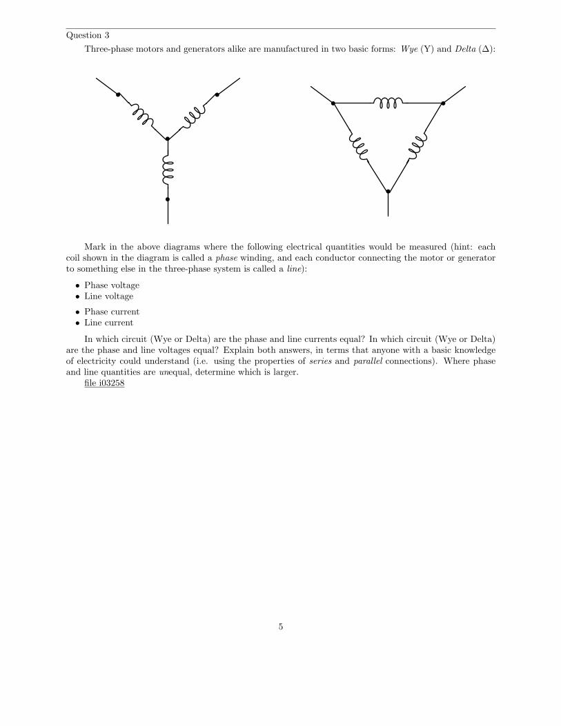
Three-phase motors and generators alike are manufactured in two basic forms: Wye (Y) and Delta (∆):
Mark in the above diagrams where the following electrical quantities would be measured (hint: eachcoil shown in the diagram is called a phase winding, and each conductor connecting the motor or generatorto something else in the three-phase system is called a line):
• Phase voltage• Line voltage
• Phase current• Line current
In which circuit (Wye or Delta) are the phase and line currents equal? In which circuit (Wye or Delta)are the phase and line voltages equal? Explain both answers, in terms that anyone with a basic knowledgeof electricity could understand (i.e. using the properties of series and parallel connections). Where phaseand line quantities are unequal, determine which is larger.
file i03258
5

Question 4
Source Motor
Identify points within this circuit absolutely guaranteed to share the same current, whether or not thesource or load happen to be balanced.
Identify point-pairs within this circuit absolutely guaranteed to share the same voltage between them,whether or not the source or load happen to be balanced.
Now suppose one of the windings inside the motor fails open. Answer both of the above questions forthis new (faulted) scenario:
Source Motor
failed open
file i04458
6

Question 5
In this Y-Y system, the source outputs balanced voltages (i.e. all line voltages are 480 VAC, shifted120o from each other) but the load is imbalanced:
Source Load
1.5 kΩ
480 V 480 V
480 V
1.1 kΩ
1.8 kΩ
Identify points within this circuit absolutely guaranteed to share the same current, despite theimbalanced load.
Identify pairs of points within this circuit absolutely guaranteed to share the same voltage, despite theimbalanced load.
Now suppose the centers of the wye source and wye load were connected together to form a 4-wire
three-phase circuit. Determine the amount of voltage between each terminal of the wye-connected sourceand earth ground.
file i04726
Question 6
Calculate the amount of current passing through each of the phase windings of this 100 horsepowerelectric motor while operating at full load, assuming a line voltage of 460 volts, 100% motor efficiency, anda power factor of 1:
Motor
100 HP
Iphase =
file i01297
7
Question 7
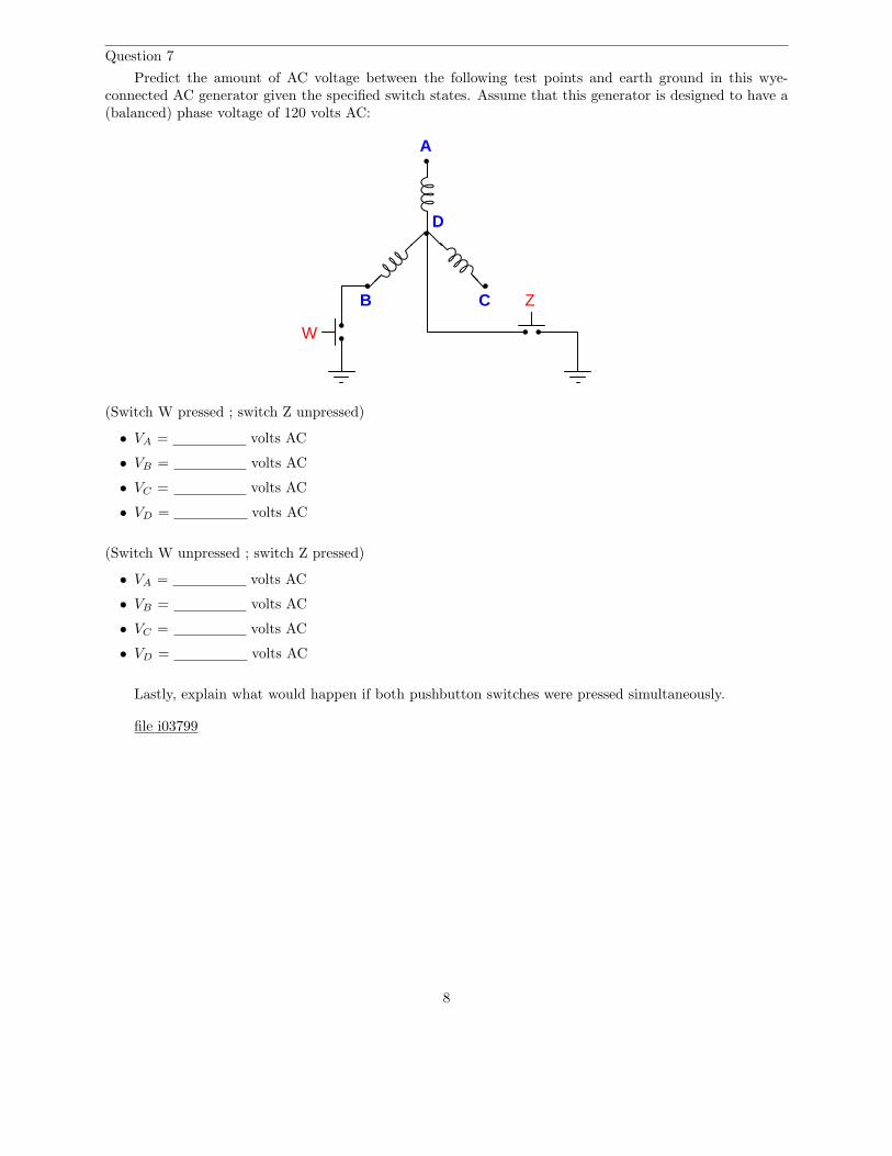
Predict the amount of AC voltage between the following test points and earth ground in this wye-connected AC generator given the specified switch states. Assume that this generator is designed to have a(balanced) phase voltage of 120 volts AC:
A
B C
D
W
Z
(Switch W pressed ; switch Z unpressed)
• VA = volts AC
• VB = volts AC
• VC = volts AC
• VD = volts AC
(Switch W unpressed ; switch Z pressed)
• VA = volts AC
• VB = volts AC
• VC = volts AC
• VD = volts AC
Lastly, explain what would happen if both pushbutton switches were pressed simultaneously.
file i03799
8
Question 8
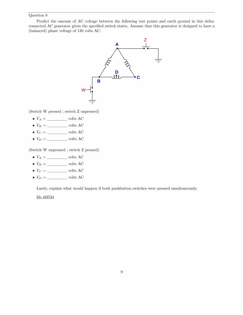
Predict the amount of AC voltage between the following test points and earth ground in this delta-connected AC generator given the specified switch states. Assume that this generator is designed to have a(balanced) phase voltage of 120 volts AC:
A
BC
D
W
Z
(Switch W pressed ; switch Z unpressed)
• VA = volts AC
• VB = volts AC
• VC = volts AC
• VD = volts AC
(Switch W unpressed ; switch Z pressed)
• VA = volts AC
• VB = volts AC
• VC = volts AC
• VD = volts AC
Lastly, explain what would happen if both pushbutton switches were pressed simultaneously.
file i03534
9

Question 9
Calculate the following circuit values, assuming a balanced three-phase system:
325 Ω
1.02 A
• Vphase (source) =
• Iphase (source) =
• Vphase (load) =
• Iphase (load) =
• Vline =
• Iline =
• Ptotal =
file i01193
10
Question 10
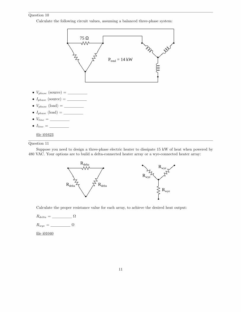
Calculate the following circuit values, assuming a balanced three-phase system:
75 Ω
Ptotal = 14 kW
• Vphase (source) =
• Iphase (source) =
• Vphase (load) =
• Iphase (load) =
• Vline =
• Iline =
file i01623
Question 11
Suppose you need to design a three-phase electric heater to dissipate 15 kW of heat when powered by480 VAC. Your options are to build a delta-connected heater array or a wye-connected heater array:
Rdelta
Rdelta Rdelta
Rwye
Rwye
Rwye
Calculate the proper resistance value for each array, to achieve the desired heat output:
Rdelta = Ω
Rwye = Ω
file i01040
11

Question 12
A three-phase electric motor operating at a line voltage of 4160 volts AC (RMS) draws 27.5 amps ofcurrent (RMS) through each of its lines. Calculate the amount of electrical power consumed by this motor.
Assuming the motor is 92% efficient and operating at a power factor of 1, calculate its mechanical outputpower in the unit of horsepower.
file i01206
Question 13
Calculate the full-load line current for a three-phase motor, given a horsepower rating of 150 HP, anefficiency of 93%, and a line voltage of 480 volts. Provide one answer for full-load line current assumingperfect power factor (1), and another answer for full-load line current assuming a power factor of 0.90.
file i02293
Question 14
Suppose the current through each of the ammeters is 2.81 amps, and the ratio of each current transformeris 100:5. Calculate the horsepower output of this AC motor, assuming a power factor of 1 and an efficiencyof 88%:
Motor
Shaft
Res
et
480 VAC3-phase
T1 T2 T3
100:5
100:5
100:5
Ammeters
Fuses Contactor
Thermal overload
P = horsepower
file i01045
12
Question 15
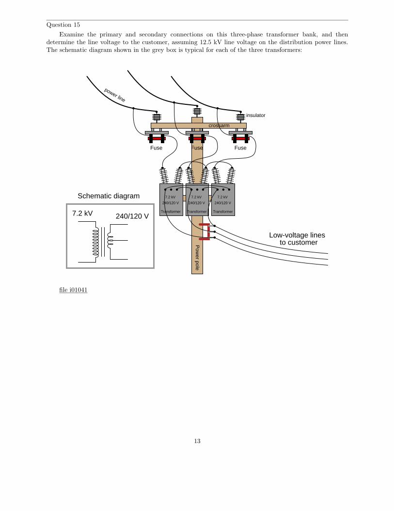
Examine the primary and secondary connections on this three-phase transformer bank, and thendetermine the line voltage to the customer, assuming 12.5 kV line voltage on the distribution power lines.The schematic diagram shown in the grey box is typical for each of the three transformers:
Pow
er pole
crossarm
insulator
power line
Transformer
Low-voltage linesto customer
Fuse
7.2 kV
240/120 V
7.2 kV 240/120 V
Schematic diagram
Transformer
7.2 kV
240/120 V
Transformer
7.2 kV
240/120 V
Fuse Fuse
file i01041
13

Question 16
Three step-down transformers have their primary (high-voltage) terminals connected together in a “wye”configuration so that the 12.5 kV line voltage energizes each primary winding with 7.2 kV. The secondaryterminals on each transformer have been left disconnected:
Pow
er pole
crossarm
insulator
power line
Transformer
Low-voltage linesto customer
Fuse
7.2 kV
240/120 V
7.2 kV 240/120 V
Schematic diagram
Transformer
7.2 kV
240/120 V
Transformer
7.2 kV
240/120 V
Fuse Fuse
L1
L2
L3
N
Sketch proper wire connections to provide 120/208 VAC to the customer.file i01042
14

Question 17
Calculate the operating current through each of the load resistances shown in this circuit (assumingeach three-phase load is balanced):
Vline = 13.8 kV
A
B
C
R1
1240 Ω
16.67:1 16.67:1 16.67:1
R2
950 Ω
Also, calculate the power dissipated by each load.file i02119
15
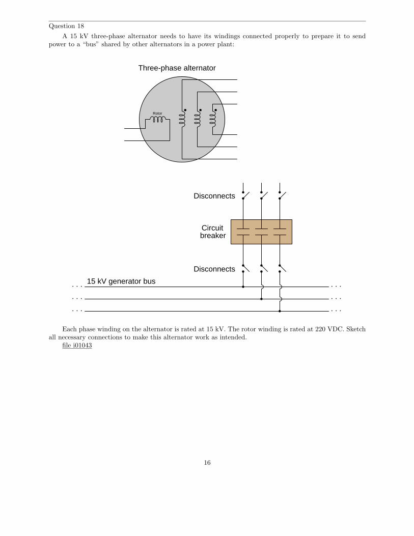
Question 18
A 15 kV three-phase alternator needs to have its windings connected properly to prepare it to sendpower to a “bus” shared by other alternators in a power plant:
Rotor
Three-phase alternator
Disconnects
Disconnects
Circuitbreaker
. . .
. . .
. . .
. . .
. . .
. . .
15 kV generator bus
Each phase winding on the alternator is rated at 15 kV. The rotor winding is rated at 220 VDC. Sketchall necessary connections to make this alternator work as intended.
file i01043
16

Question 19
An unbalanced wye-connected load receives power from a balanced 120/208 VAC source:
L1
N
L2
L3
120/208 VACbalanced source
1k5 Ω
2k3 Ω 0k8 Ω
R1
R2 R3
Calculate the current through each of the three lines (L1, L2, and L3), as well as the current throughthe neutral conductor:
• IL1 = amps
• IL2 = amps
• IL3 = amps
• IN = amps
file i01044
17
Question 20
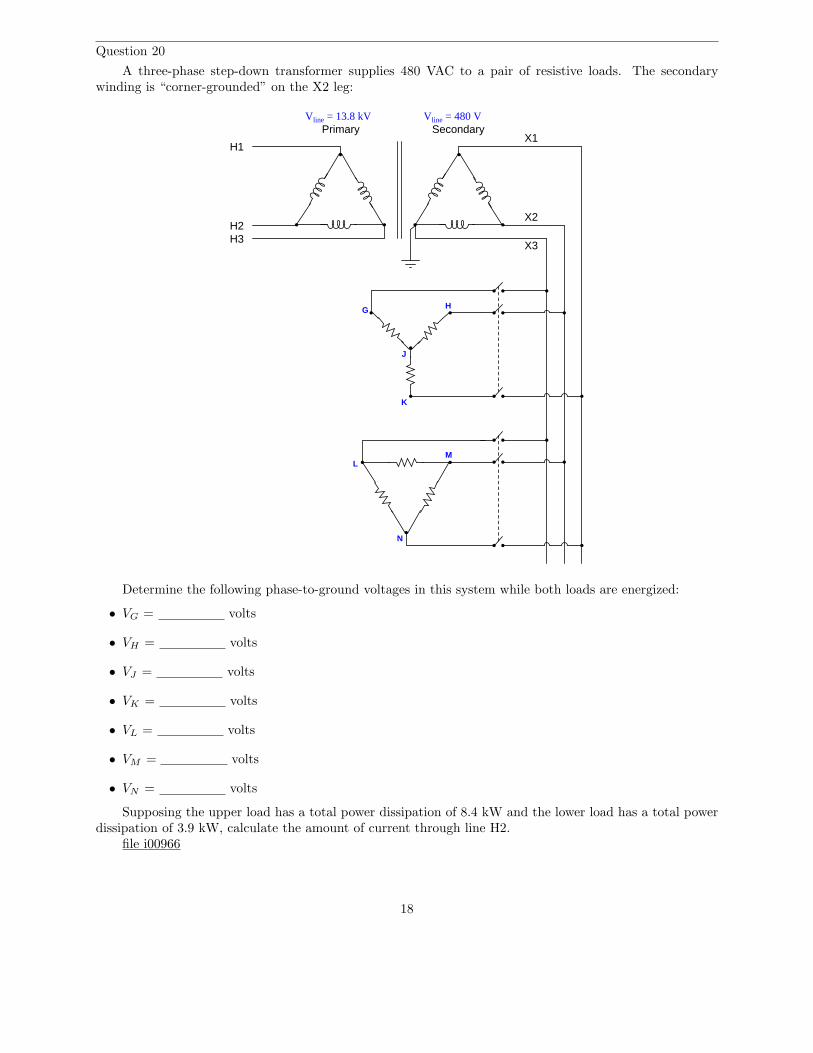
A three-phase step-down transformer supplies 480 VAC to a pair of resistive loads. The secondarywinding is “corner-grounded” on the X2 leg:
Primary SecondaryVline = 13.8 kV Vline = 480 V
H1
H2H3
X1
X2
X3
G H
K
J
LM
N
Determine the following phase-to-ground voltages in this system while both loads are energized:
• VG = volts
• VH = volts
• VJ = volts
• VK = volts
• VL = volts
• VM = volts
• VN = volts
Supposing the upper load has a total power dissipation of 8.4 kW and the lower load has a total powerdissipation of 3.9 kW, calculate the amount of current through line H2.
file i00966
18
Question 21
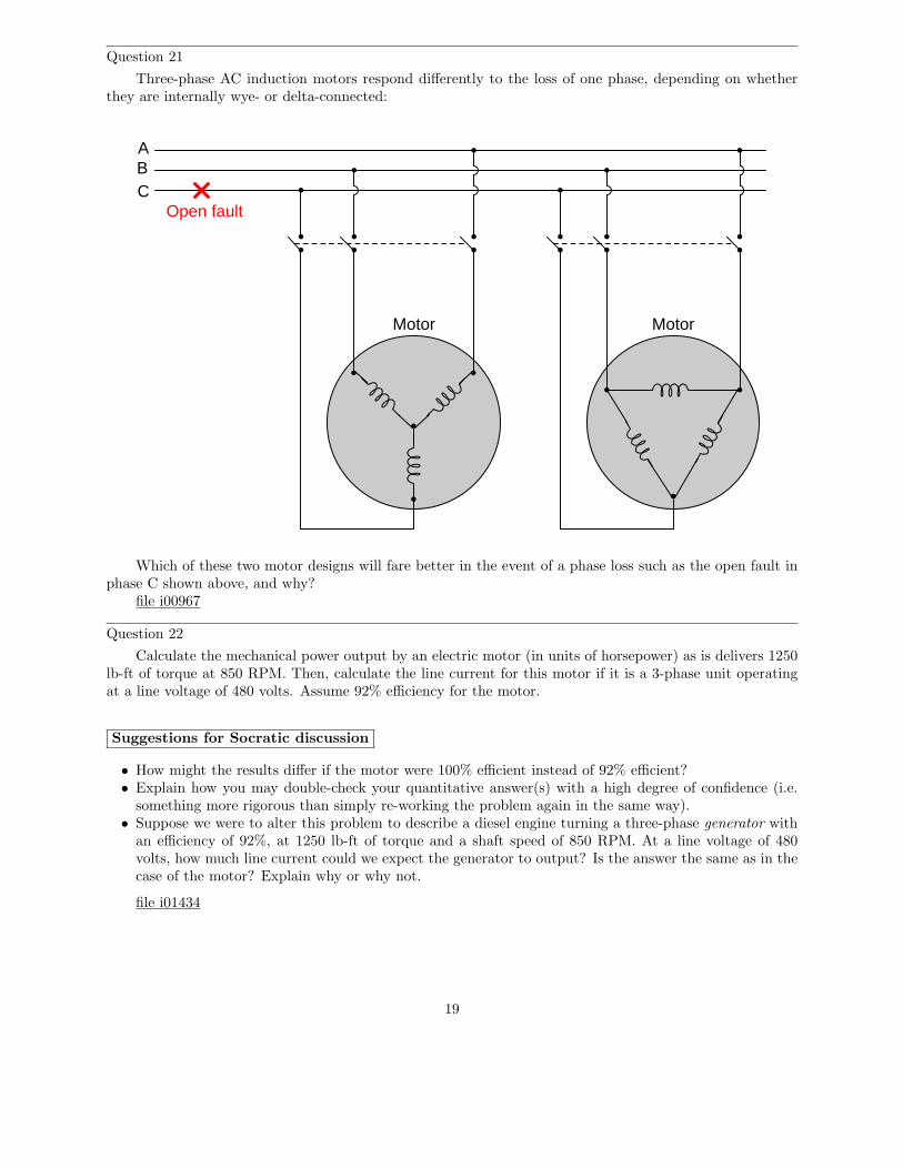
Three-phase AC induction motors respond differently to the loss of one phase, depending on whetherthey are internally wye- or delta-connected:
Motor Motor
ABC
Open fault
Which of these two motor designs will fare better in the event of a phase loss such as the open fault inphase C shown above, and why?
file i00967
Question 22
Calculate the mechanical power output by an electric motor (in units of horsepower) as is delivers 1250lb-ft of torque at 850 RPM. Then, calculate the line current for this motor if it is a 3-phase unit operatingat a line voltage of 480 volts. Assume 92% efficiency for the motor.
Suggestions for Socratic discussion
• How might the results differ if the motor were 100% efficient instead of 92% efficient?• Explain how you may double-check your quantitative answer(s) with a high degree of confidence (i.e.
something more rigorous than simply re-working the problem again in the same way).• Suppose we were to alter this problem to describe a diesel engine turning a three-phase generator with
an efficiency of 92%, at 1250 lb-ft of torque and a shaft speed of 850 RPM. At a line voltage of 480volts, how much line current could we expect the generator to output? Is the answer the same as in thecase of the motor? Explain why or why not.
file i01434
19
Answers
Answer 1
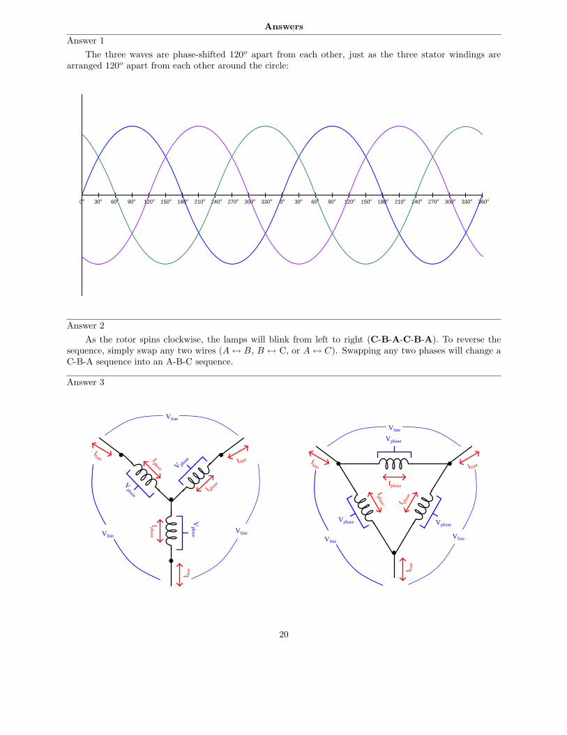
The three waves are phase-shifted 120o apart from each other, just as the three stator windings arearranged 120o apart from each other around the circle:
90o60030o 120o 150o 180o 210o 240o 270o 300o 330o0o 90o60030o 120o 150o 180o 210o 240o 270o 300o 330o 360o0o
Answer 2
As the rotor spins clockwise, the lamps will blink from left to right (C-B-A-C-B-A). To reverse thesequence, simply swap any two wires (A ↔ B, B ↔ C, or A ↔ C). Swapping any two phases will change aC-B-A sequence into an A-B-C sequence.
Answer 3
Vphase
Vline
Iphase
Iphase
I phas
e
Iline I line
I line
Iline I line
I line
Iphase
Iphase
I phas
e
Vphase Vphase
V phas
e
Vphase
VphaseVline
Vline
VlineVline
Vline
20

Wye configuration
• Iphase = Iline
• Vphase < Vline
Delta configuration
• Vphase = Vline
• Iphase < Iline
Answer 4
The current carried by each line will be absolutely equal to the current carried by its respective phasecoil within the wye-connected source, for the simple reason that each line is in series with each phase elementof a wye network, and series components share the same current (there being only one path between thosecomponents for current to flow). If either source or load are imbalanced, we would not expect any oneline’s current to equal any other line’s current, but each line’s current will be the same as the wye-coil it’sconnected to.
Similarly, we may conclude that voltage measured between any pair of parallel-connected points mustbe equal. In this circuit, an example of that would be the voltage measured between any two lines and thevoltage of the phase coil between those same lines within the delta-connected motor.
When the upper phase coil within the motor fails open, it forces the remaining two phase coils to be inseries with the upper two lines (one line per coil). This means each of the functional coils within the motorwill share current equally with its respective line and respective phase coil within the wye-connected source.Voltage will be unaffected, still equal between sets of parallel-connected point-pairs.
Incidentally, the motor’s new winding configuration is called open-delta, and it is a legitimate way toconfigure certain three-phase loads!
21
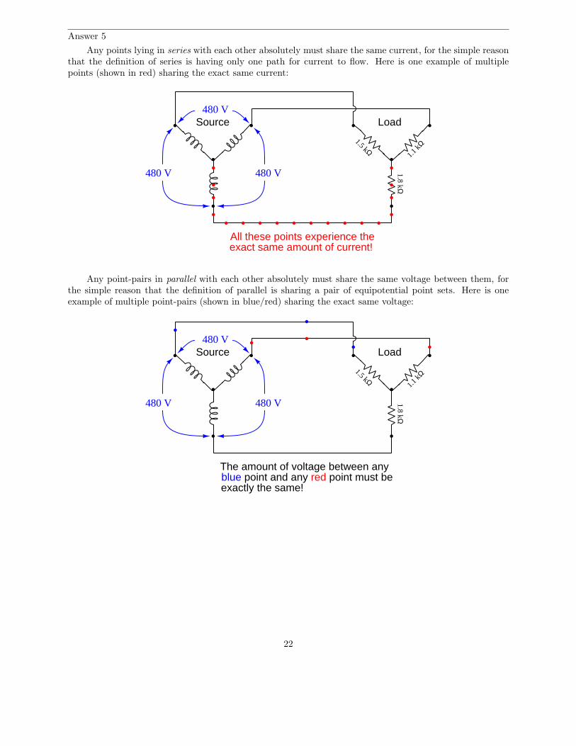
Answer 5
Any points lying in series with each other absolutely must share the same current, for the simple reasonthat the definition of series is having only one path for current to flow. Here is one example of multiplepoints (shown in red) sharing the exact same current:
Source Load
1.5 kΩ
480 V 480 V
480 V
1.1 kΩ
1.8 kΩ
All these points experience theexact same amount of current!
Any point-pairs in parallel with each other absolutely must share the same voltage between them, forthe simple reason that the definition of parallel is sharing a pair of equipotential point sets. Here is oneexample of multiple point-pairs (shown in blue/red) sharing the exact same voltage:
Source Load
1.5 kΩ
480 V 480 V
480 V
1.1 kΩ
1.8 kΩ
The amount of voltage between anyblue point and any red point must beexactly the same!
22
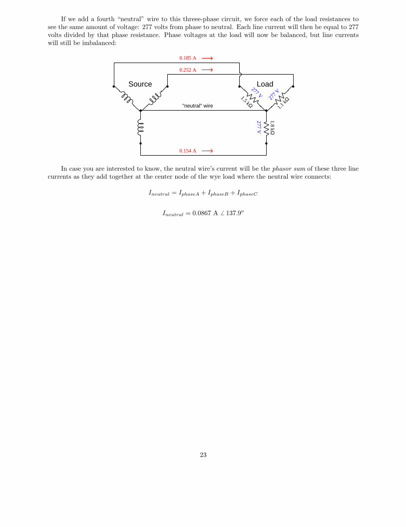
If we add a fourth “neutral” wire to this threee-phase circuit, we force each of the load resistances tosee the same amount of voltage: 277 volts from phase to neutral. Each line current will then be equal to 277volts divided by that phase resistance. Phase voltages at the load will now be balanced, but line currentswill still be imbalanced:
Source Load
1.5 kΩ1.1
kΩ
1.8 kΩ
277 V27
7 V
277 V
0.185 A
0.252 A
0.154 A
"neutral" wire
In case you are interested to know, the neutral wire’s current will be the phasor sum of these three linecurrents as they add together at the center node of the wye load where the neutral wire connects:
Ineutral = IphaseA + IphaseB + IphaseC
Ineutral = 0.0867 A 6 137.9o
23
Answer 6
Line current is easy to calculate, after converting 100 HP into 74600 watts:
P =√
3IlineVline
Iline =P
√3Vline
Iline =74600 W√
3(460 V)
Iline = 93.63 A
However, we need to know the amount of phase current in each of the motor’s windings, and sincethe motor is wound in a delta fashion we know that line current is not equal to phase current (i.e. eachline current “splits” into smaller phase currents at each of the nodes where lines join the delta network, inaccordance with Kirchhoff’s Current Law).
Being a balanced three-phase load, this “splitting” of current will follow the ratio of 1√3:
Iphase =Iline√
3
Iphase =93.63 A
√3
Iphase = 54.06 A
An alternative approach to solving for phase current would be to realize that in a balanced three-phaseload, each of the three phases handles exactly one-third of the total power. There is no
√3 factor in dividing
power amongst the phase windings because energy is a scalar quantity and always adds directly, unlikevoltage or current which are phasor quantities and must relate trigonometrically.
Since the total power in this case is 74600 watts, each of the three phase windings within the motorwill convert one-third of that total electrical power (i.e. 24866.7 watts) into mechanical power. Since we cantell phase elements in a delta-connected network will experience line voltage (because each phase elementis in parallel with a pair of power lines, and parallel-connected components always share the same voltage),we may treat each of the phase windings as a single-phase load. Calculating current for a single-phase loadgiven power and voltage:
P = IV
I =P
V
I =24866.7 W
460 V
I = 54.06 A
24
Answer 7
With switch W pressed, test point B will be equipotential with (i.e. “electrically common” to) earthground. This ensures test point B will register 0 volts with respect to ground, because test point B is
grounded. Test point D will now register one phase voltage (120 volts), while test points A and C willregister line voltage (208 volts).
With switch Z pressed, test point D will now be grounded and register 0 volts. Test points A, B, andC will each register 120 volts to ground: their respective phase voltages.
Pressing both pushbuttons simultaneously is a bad idea, because it will directly short the phase B windingof the generator. This will cause excessive current to flow through that winding, most likely damaging it.
Answer 8
With switch W pressed, test point B will be equipotential with (i.e. “electrically common” to) earthground. This ensures test point B will register 0 volts with respect to ground, because test point B is
grounded. Test point D will now register one-half of the nominal phase voltage (i.e. VD = 60 volts), whiletest points A and C will register line voltage which is the same as phase voltage for a delta-connected network(120 volts).
With switch Z pressed, test point A will now be grounded and register 0 volts. Test points B and Cwill each register 120 volts to ground: their respective phase (and line) voltages. Test point D will register
104 volts (120 volts × cos 30o = 120√
3
2).
Pressing both pushbuttons simultaneously is a bad idea, because it will directly short the left-handphase winding of the generator. This will cause excessive current to flow through that winding, most likelydamaging it.
Answer 9
• Vphase (source) = 574.2 V
• Iphase (source) = 0.589 A
• Vphase (load) = 331.5 V
• Iphase (load) = 1.02 A
• Vline = 574.2 V
• Iline = 1.02 A
• Ptotal = 1014.4 W
Answer 10
• Vphase (source) = 341.6 V
• Iphase (source) = 13.663 A
• Vphase (load) = 591.6 V
• Iphase (load) = 7.888 A
• Vline = 591.6 V
• Iline = 13.663 A
25
Answer 11
Perhaps the simplest approach to this problem is to calculate the power dissipation of each resistor insideof each three-resistor array. Since power is a scalar quantity (i.e. it adds directly, not trigonometrically),the 15 kW total heat output of each array means each resistor inside of each array must dissipate 5 kW ofpower.
In the delta-connected heater, each resistor sees full line voltage (480 VAC), therefore the resistancemay be calculated as such:
R =V 2
P=
4802
5000= 46.08 Ω
In the wye-connected heater, each resistor sees 1√3
of the full line voltage (480 VAC), which is 277.1
VAC. Therefore the resistance may be calculated as such:
R =V 2
P=
277.12
5000= 15.36 Ω
Answer 12
Pelec = 198.146 kVA = 265.61 HP
Pmech = 244.36 HP
Answer 13
The direct equivalence between horsepower and watts is 746 watts to 1 horsepower. Therefore, a 150HP motor ideally consumes 111,900 watts (perfect efficiency). With an energy conversion efficiency of 93%,though, this input power figure will be larger than 111,900 watts to account for energy wasted in heat. Thus,our actual input power requirement for this 150 HP motor is 120,322.5 watts.
Applying the standard three-phase power formula, we may solve for line current assuming a perfectpower factor:
Ptotal =√
3(Iline)(Vline)
Iline =Ptotal
√3(Vline)
Iline =120322.5√
3(480)= 144.73 amps
Now, a power factor of less than 1 means some of the line current will not be performing useful work, butinstead will be involved with the alternating exchange of energy stored and released by the load’s inductance.With a power factor figure of 0.9, only 90% of the line current will be doing real work. We may deal withthis percentage figure in much the same way as we dealt with efficiency: dividing the ideal line current bythis figure will yield the actual line current for the motor:
Iline = 160.81 amps (at a power factor of 0.9)
26
Answer 14
With 100:5 ratios at each CT, the line current to this motor is twenty times the amount of currentthrough each ammeter:
(2.81)
(
100
5
)
= 56.2 amps
At a line voltage of 480 VAC and a line current of 56.2 amps, the total electrical power in this 3-phasesystem may be calculated as follows:
Ptotal = (√
3)(Iline)(Vline)
Ptotal = (√
3)(56.2)(480) = 46.724 kW
At an efficiency of 88%, only 88% of this power becomes translated into mechanical horsepower. Thisequates to 41.117 kW of mechanical power output at the motor shaft.
Since we know there are 746 watts to every horsepower, we may convert this kW figure into HP asfollows:
(
41117 W
1
) (
1 HP
746 W
)
= 55.12 HP
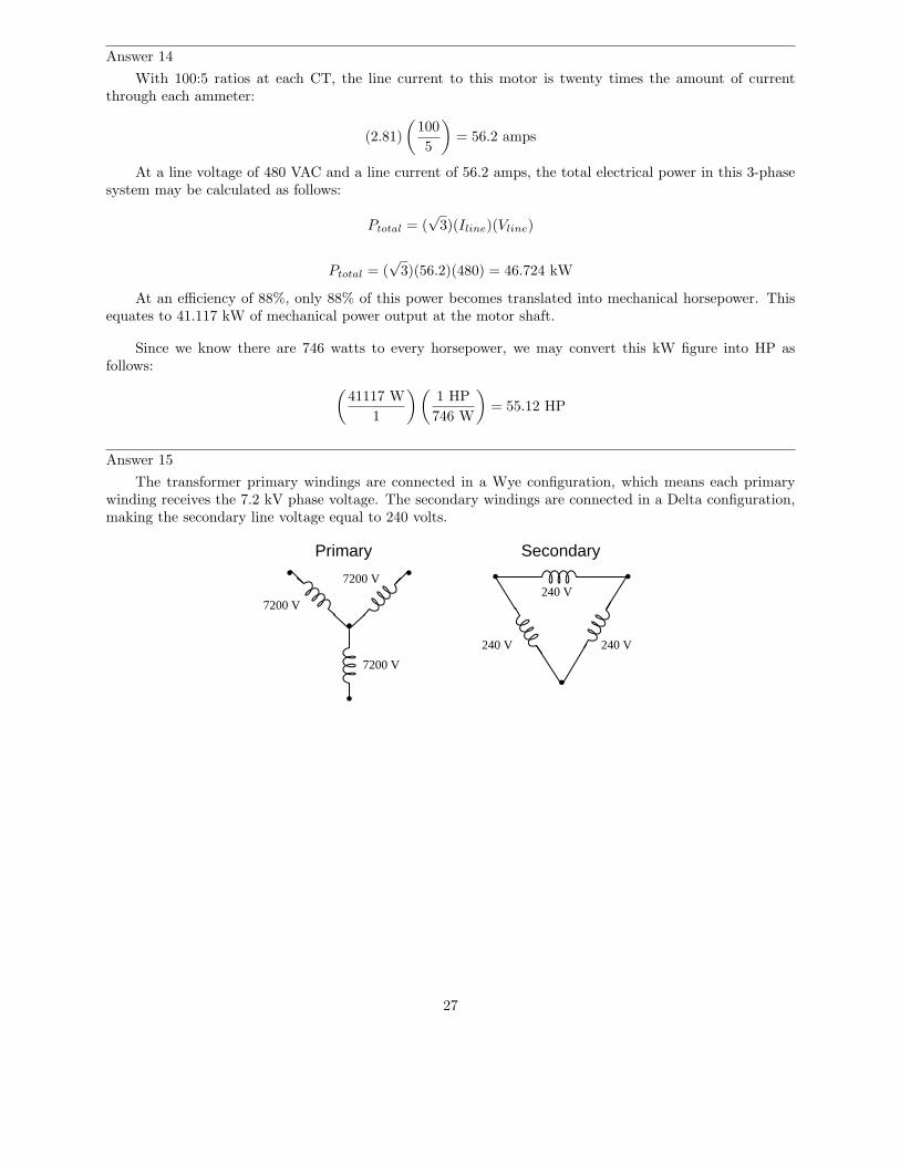
Answer 15
The transformer primary windings are connected in a Wye configuration, which means each primarywinding receives the 7.2 kV phase voltage. The secondary windings are connected in a Delta configuration,making the secondary line voltage equal to 240 volts.
Primary Secondary
7200 V
7200 V
7200 V
240 V 240 V
240 V
27
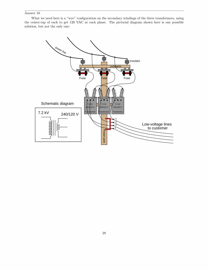
Answer 16
What we need here is a “wye” configuration on the secondary windings of the three transformers, usingthe center-tap of each to get 120 VAC at each phase. The pictorial diagram shown here is one possiblesolution, but not the only one:
Pow
er pole
crossarm
insulator
power line
Transformer
Low-voltage linesto customer
Fuse
7.2 kV
240/120 V
7.2 kV 240/120 V
Schematic diagram
Transformer
7.2 kV
240/120 V
Transformer
7.2 kV
240/120 V
Fuse Fuse
L1
L2
L3
N
28
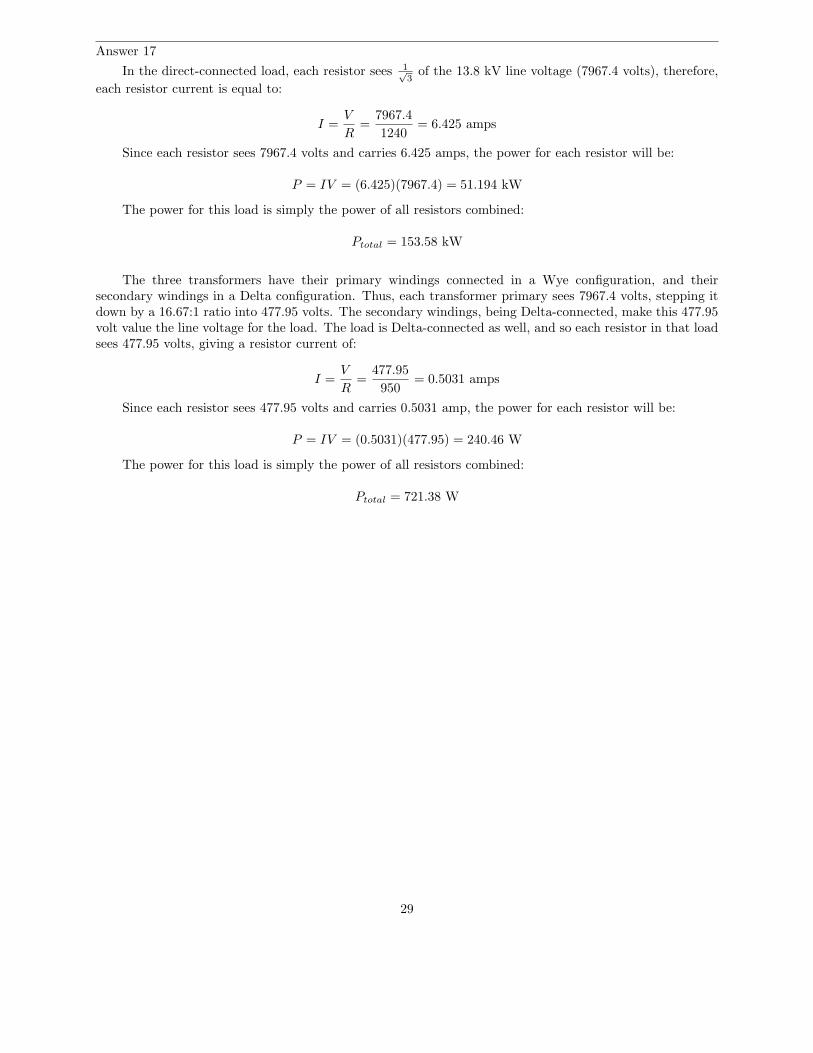
Answer 17
In the direct-connected load, each resistor sees 1√3
of the 13.8 kV line voltage (7967.4 volts), therefore,
each resistor current is equal to:
I =V
R=
7967.4
1240= 6.425 amps
Since each resistor sees 7967.4 volts and carries 6.425 amps, the power for each resistor will be:
P = IV = (6.425)(7967.4) = 51.194 kW
The power for this load is simply the power of all resistors combined:
Ptotal = 153.58 kW
The three transformers have their primary windings connected in a Wye configuration, and theirsecondary windings in a Delta configuration. Thus, each transformer primary sees 7967.4 volts, stepping itdown by a 16.67:1 ratio into 477.95 volts. The secondary windings, being Delta-connected, make this 477.95volt value the line voltage for the load. The load is Delta-connected as well, and so each resistor in that loadsees 477.95 volts, giving a resistor current of:
I =V
R=
477.95
950= 0.5031 amps
Since each resistor sees 477.95 volts and carries 0.5031 amp, the power for each resistor will be:
P = IV = (0.5031)(477.95) = 240.46 W
The power for this load is simply the power of all resistors combined:
Ptotal = 721.38 W
29
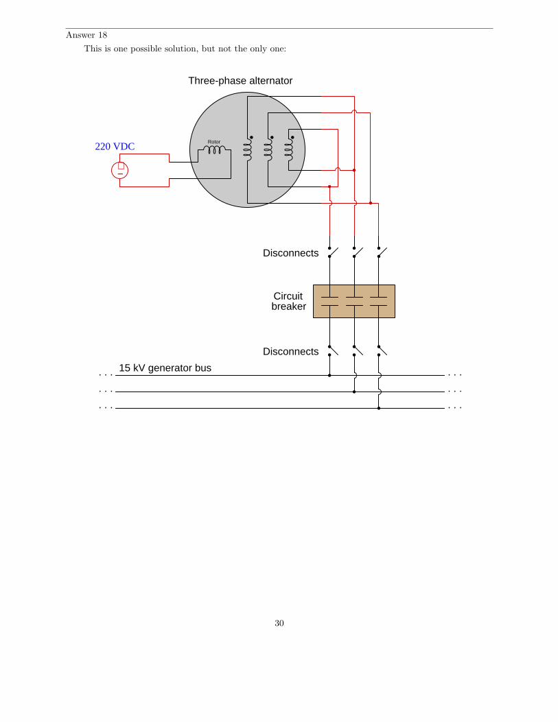
Answer 18
This is one possible solution, but not the only one:
Rotor
Three-phase alternator
Disconnects
Disconnects
Circuitbreaker
. . .
. . .
. . .
. . .
. . .
. . .
15 kV generator bus
+−
220 VDC
30
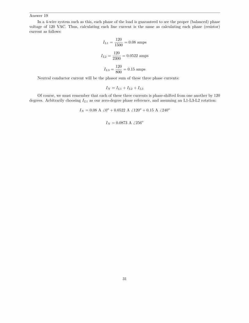
Answer 19
In a 4-wire system such as this, each phase of the load is guaranteed to see the proper (balanced) phasevoltage of 120 VAC. Thus, calculating each line current is the same as calculating each phase (resistor)current as follows:
IL1 =120
1500= 0.08 amps
IL2 =120
2300= 0.0522 amps
IL3 =120
800= 0.15 amps
Neutral conductor current will be the phasor sum of these three phase currents:
IN = IL1 + IL2 + IL3
Of course, we must remember that each of these three currents is phase-shifted from one another by 120degrees. Arbitrarily choosing IL1 as our zero-degree phase reference, and assuming an L1-L3-L2 rotation:
IN = 0.08 A 6 0o + 0.0522 A 6 120o + 0.15 A 6 240o
IN = 0.0873 A 6 256o
31
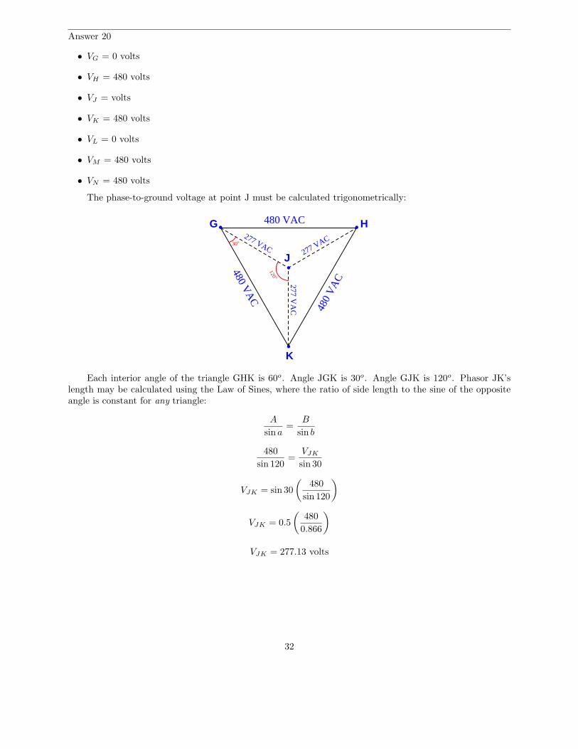
Answer 20
• VG = 0 volts
• VH = 480 volts
• VJ = volts
• VK = 480 volts
• VL = 0 volts
• VM = 480 volts
• VN = 480 volts
The phase-to-ground voltage at point J must be calculated trigonometrically:
480
VA
C480 V
AC
480 VACG H
J
K
277 VAC277 VAC
277 VA
C
30o
120 o
Each interior angle of the triangle GHK is 60o. Angle JGK is 30o. Angle GJK is 120o. Phasor JK’slength may be calculated using the Law of Sines, where the ratio of side length to the sine of the oppositeangle is constant for any triangle:
A
sin a=
B
sin b
480
sin 120=
VJK
sin 30
VJK = sin 30
(
480
sin 120
)
VJK = 0.5
(
480
0.866
)
VJK = 277.13 volts
32

Total power in this system is 12.3 kW. The line current at the primary side of the transformer (assumingno power losses in the transformer) may be calculated as follows:
Ptotal =√
3(Iline)(Vline)
Iline =Ptotal
√3(Vline)
Iline =12300
√3(13800)
Iline = 0.5146 amps
The grounding of the secondary is irrelevant to calculations of current and power, because that groundconnection conducts no current at all and dissipates no power.
Answer 21
The delta-connected motor will fare better, because it will still generate a polyphase (truly rotating)magnetic field, whereas the wye-connected motor will only generate an oscillating magnetic field. Also, thevoltage across each phase winding of the delta-connected motor will remain the same as the line voltage,while the voltage across each phase winding of the wye-connected motor will decrease from what it wasprevious to the fault.
If the motors’ mechanical loads are sufficiently light, both motors will continue to rotate. However, thedelta-connected motor will have a greater torque capacity in this phase-loss condition than the wye-connectedmotor due to the fact that its rotating magnetic field still maintains a definite direction of rotation and alsothat each of its phase windings receives the same (full) voltage as previously.
If these consequences are not clear for you to see, you might wish to apply the problem-solving techniqueof adding quantitative values to the problem. Assign a line voltage (e.g. 480 VAC) to the incoming three-phase power conductors A, B, and C. Then, analyze the voltages at each phase winding of each motor beforethe fault versus after the fault. You may also calculate the phase angle for each of these winding voltages tosee that the delta-connected motor still has three 120o-shifted voltages powering it, while the wye-connectedmotor only has one voltage (single phase) powering it.
33
Answer 22
P = 202.3 hp
If you calculated 181.5 amps for line current, you’re close – you have assumed 100% efficiency for themotor! The actual line current is 197.2 amps if you take the motor’s 92% efficiency into account.
Here is a formula you can use to convert torque (lb-ft) and speed (RPM) values into horsepower:
P =Sτ
5252.113
I don’t expect anyone to memorize a formula like this, but one may derive it from a “thoughtexperiment.” It should be intuitively obvious that power (P ) must be directly proportional to both torque(τ) and speed (S), with some constant of proportionality (k) included to account for units:
P ∝ Sτ
P = kSτ
If we were to imagine a 1-foot radius drum hoisting a 550 pound rate vertically at 1 foot per secondas an example of a machine exerting exactly 1 horsepower, we may solve for τ and S, then calculate thenecessary constant to make P equal to 1. The drum’s torque would be 550 lb-ft, of course (550 lb of forceexerted over a moment arm of 1 foot). With a circumferential speed of 1 foot per second, it would rotate at1
2πrevolutions per second, or 30
πRPM. If τ = 550 and S = 30
πand P = 1 horsepower, then:
P =πSτ
30 × 550
In answer to the Socratic discussion question, the 92% efficiency works to diminish output current,rather than increase input current as in the case of the motor. Thus, the diesel-powered generator willoutput a line current of 167 amps.
34