Embed Size (px)
Citation preview
Three-dimensional FEM model of an AC/DC hybrid high voltage transmission line to analyze the
electrical field along composite insulators
D. Potkrajac, S. Papenheim, M. Kizilcay
Abstract-To increase the power transfer capacity of existing lines, a transmission system operator in Germany plans to replace an existing 380-kV three-phase AC system into a bipolar HVDC system on the same tower that is called a “hybrid line”. Due to the proximity of AC transmission systems and the HVDC system electrical and magnetic coupling effects between those lines are present during system operation. The mutual influence of the electromagnetic fields between the AC and DC systems can cause changes in electrical components. The electrical performance of a composite insulator is affected by the electrical field distribution along its length and surface. The calculation of the electric field distribution is very important for the design of EHV transmission lines. The insulators are an important part of the transmission lines to prevent tripping of the transmission line by a flashover over the insulator. The electrical field distribution around the composite insulators and the heads of transmission towers is numerical calculated using finite element method. The calculations were executed in the time domain. A three-dimensional (3D) model of a hybrid transmission line for a given tower configuration has been developed and the model is presented in this paper. The geometric dimensions and material properties of an insulator are taken into consideration. In this paper a field calculation program called COMSOL Multiphysics is used. COMSOL Multiphysics is a powerful simulation software that uses finite element method (FEM) to simulate multi-field problems. COMSOL has the ability of spatial transient electromagnetic field calculation in time domain. The electrical field distribution around three 380-kV AC System and one 400-kV bipolar DC system is analyzed.
Keywords: FEM. , Three dimensional, AC/DC hybrid,
COMSOL Multiphysics
I. INTRODUCTION The electrical power consumption in the world is growing
and therefore there is a need for additional capacities in form of new transmission lines. Beside common HVAC technology HVDC technology is considered to be an attractive alternative, due to lower losses, better controllability and the lack of reactive power consumption. The erection of new transmission lines is often associated with demanding approval procedures and conflicts of interests. One possible solution is the D. Potkrajac, S. Papenheim and M. Kizilcay are with the Dept. of Electrical Eng. and Computer Science of the University of Siegen in Siegen, Germany. (e-mail of corresponding author: [email protected]) Paper submitted to the International Conference on Power Systems Transients (IPST2017) in Seoul, Republic of Korea June 26-29, 2017
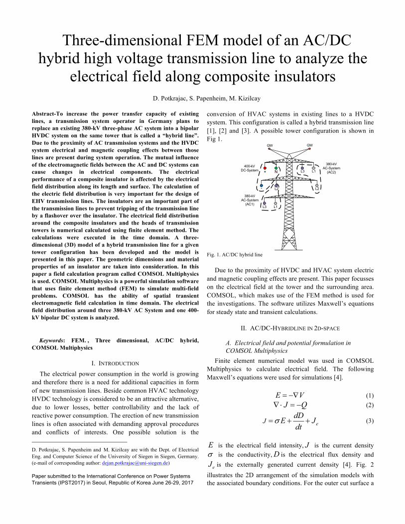
conversion of HVAC systems in existing lines to a HVDC system. This configuration is called a hybrid transmission line [1], [2] and [3]. A possible tower configuration is shown in Fig 1.
380-kV AC-System
(AC2)+
-
N400-kV
DC-System
L1
GWGW
380-kV AC-System
(AC1)
L2
L3
L1
L2
L3
Fig. 1. AC/DC hybrid line
Due to the proximity of HVDC and HVAC system electric
and magnetic coupling effects are present. This paper focusses on the electrical field at the tower and the surrounding area. COMSOL, which makes use of the FEM method is used for the investigations. The software utilizes Maxwell’s equations for steady state and transient calculations.
II. AC/DC-HYBRIDLINE IN 2D-SPACE
A. Electrical field and potential formulation in COMSOL Multiphysics
Finite element numerical model was used in COMSOL Multiphysics to calculate electrical field. The following Maxwell’s equations were used for simulations [4]. E V= -Ñ (1) J QÑ× = - (2)
eJdDE Jdt
s= + + (3)
E is the electrical field intensity, J is the current density s is the conductivity,D is the electrical flux density and
eJ is the externally generated current density [4]. Fig. 2 illustrates the 2D arrangement of the simulation models with the associated boundary conditions. For the outer cut surface a

homogeneous Neumann boundary condition is applied. The bottom surface (ground) is set to Dirichlet boundary condition of 0 V. Table 1 documents the specific parameters of the simulation model.
0V =
0Vn
¶=
Ground
DCV + DC NV
DCV -
1 3AC LV
2 2AC LV
2 1AC LV
1 1AC LV
1 2AC LV
2 3AC LV
x
GWV GWV
y
Neumann
Dirichlet Fig. 2. 2D-Space Model of AC/DC hybrid line including the boundary condition
TABLE I PARAMETERS OF THE SIMULATION MODEL
HVDC-System VDC+=400 kV VDC N=0 V VDC-=-400 kV
380-kV-AC-System (AC1)
VL1=380 kV·sin(ωt) VL2=380 kV·sin(ωt +2π/3) VL3=380 kV·sin(ωt -4π/3)
380-kV-AC-System (AC2)
VL1=380 kV·sin(ωt) VL2=380 kV·sin(ωt +2π/3) VL3=380 kV·sin(ωt -4π/3)
Ground Wire VGW=0 V
B. Influence of the DC systems on the AC-system To study the basic phenomena in the time domain only the
conductors, including the ground wires, are modelled in COMSOL. The tower is neglected. Fig. 3 shows the 2D model and visualizes the electrical potential in kV.
Fig. 3. Electrical potential of the simulated AC/DC hybrid line
To investigate the influence of the hybrid transmission line, two simulations are carried out. Fig. 4 shows the transmission tower before (see Fig. 4.a) and after (see Fig. 4.b) the
conversion to a hybrid tower.
1 x 380-kV AC
L1
GWGW
2 x 380-kV AC
L2
L3
L1
L2
L3L3L1
L2
1 x 380-kV AC
+
-
N
400-kV DC
L1
GWGW
1 x 380-kV AC
L2
L3
L1
L2
L3
Fig. 4a. 3 x 380-kV AC systems
Fig.4b. 1 x bipolar HVDC system and 2x380-kV AC systems
A detailed view of the electrical field at 2 m above the
ground is shown in Fig. 5 for the transmission tower with three AC systems. The meshed surface is a result of the superposition of discrete time points. The electrical field of the AC/DC hybrid transmission line is shown in Fig. 6. The electrical field of the hybrid line is more unsymmetrical and has a higher amplitude under the HVDC system compared with the pure AC transmission line.
Fig. 5. Electrical field 2 m above the ground level 3x 380-kV AC systems
Fig. 6. Electrical field 2 m above the ground level 1x bipolar HVDC system 2x 380-kV AC systems

For verification purposes the position of the HVDC system is changed (see Fig. 7). The simulation results are shown in Fig. 8 to Fig. 10. At all configurations the electrical field under the HVDC system has a higher amplitude compared to the pure HVAC systems (see Fig. 5).
Fig. 7. Three different configurations of the AC/DC hybrid line
Fig. 8. Electrical field 2 m above the ground level for the first configuration
Fig. 9. Electrical field 2 m above the ground level for the second configuration
Fig. 10. Electrical field 2 m above the ground level for the third
configuration
Furthermore, the influence of transposed phase conductors of a AC-System on the electrical field will be investigated. For this investigation, the phase arrangement of the AC/DC hybrid line corresponds to the first configuration (see
Fig.7). The following configuration is used for the transposition.
1L
2L
3L
1L
2L
3L Fig. 11. Transposition scheme
In this investigative series two different scenarios exist. In
the first scenario only the conductors of the 380-kV AC system “AC1” will be transposed. In the second scenario only the conductors of the 380-kV AC system with the identifier “AC2” will be transposed. Table 2 documents clearly the individual scenarios. Fig. 12 and the Fig. 13 illustrate the electrical field for both scenarios.
TABLE II TWO DIFFERENT SCENARIOS
Scenario 1 (AC/DC hybrid line first configuration)
AC1 AC2 L1 L2 L1 L1 L2 L1 L2 L2 L3 L3 L3 L3
Scenario 2 (AC/DC hybrid line first configuration)
AC1 AC2
L1 L1 L1 L2
L2 L2 L2 L1
L3 L3 L3 L3
1 x 380-kV AC
+
-
N
400-kV DC
L1
GWGW
1 x 380-kV AC
L2
L3
L1
L2
L3
1 x 380-kV AC
+ -
N
400-kV DC
L1
GWGW
1 x 380-kV AC
L2
L3
L1
L2
L3
1 x 380-kV AC
+
- N
400-kV DC
L1
GWGW
1 x 380-kV AC
L2
L3
L1
L2
L3
AC/DC hybrid line first configuration
AC/DC hybrid line second configuration
AC/DC hybrid line third configuration

Fig. 12. Electrical field 2 m above the ground level for the first scenario
(AC/DC hybrid first configuration)
Fig. 13. Electrical field 2 m above the ground level for the second scenario
(AC/DC hybrid first configuration)
As it can be seen from the figures, the electric field is additionally influenced by the arrangement of the individual phases. A homogenization of the electrical field in scenario 1 is recognizable. In scenario 2 it can be seen that this transposing configuration has a major influence on the electrical field.
C. Influence of AC-systems on DC-system The HVAC systems work with a base frequency of 50-Hz
in the considered case. Due to the proximity, the HVDC system is stressed with a permanent 50-Hz signal, resulting from capacitive coupling as in this simulations only the electrical filed is considered. The 2D simulation model is used again for the computations (see Fig. 3). Fig 14 shows the simulation results in the time domain for the 50-Hz coupled voltages in the three conductors of the HVDC system. The voltages are unsymmetrical and in the range of 40 kV.
Fig. 14. The coupled fundamental frequency voltage on the conductors of DC poles using COMSOL Multiphysics
To verify the computations by COMSOL Multiphysics the simulation program PSCAD/EMTDC [7] is used. The same tower geometry that was used in COMSOL is now used in PSCAD/EMTDC to model the transmission lines. Fig. 15 illustrates the simplified simulation model. The transmission lines are energized through two 380-kV AC systems, and the 50-Hz components are measured on the HVDC lines.
380kV
380kVOpenEnd
OpenEnd
U50Hz
50-HzEnergizationofAC/DChybridline
DC
AC1
AC2
Fig. 15. Simplified simulation model in PSCAD/EMTDC
Comparing the results from the Fig. 14 and the Fig. 16, it can be seen that they are nearly identical. Completely different computation program produces in this case the same 50-Hz coupled voltages in the three conductors of the HVDC system.
Fig. 16. The coupled fundamental frequency voltage on the conductors of DC poles using PSCAD/EMTDC

III. AC/DC-HYBRIDLINE IN 3D-SPACE As the HVDC system is stressed with a DC-field and a
superimposed fundamental frequency field the influence of the insulators plays an important role. For this purpose the 2D model was expanded to a 3D model. The boundary condition that were used for 2D model are also used for the 3D model.
The 3D model represents a 500 m section of a hybrid line and is shown in Fig 17. Besides the conductors the tower, ground wires and insulators are considered (see detailed view in Fig. 18).
Fig. 17. 3D model of the hybrid transmission line in COMSOL
Fig. 18. 3D model of the hybrid transmission line (detailed view)
The core of the composite insulator consists of Fiber Reinforced Plastic (FRP). For the electrical insulation of the core and to protect the core from weather sheds a Silicon Rubber (SIR) is used. Fig. 19 shows the 3D model and the cross section view of the composite insulator. The simulation parameters of the insulator are given in Table 3 [5].
FRP
core
3D-structure of
the composite insulator 2D-Cross section view of
composite insulator Fig. 19. Structure of a composite insulator
TABLE III INSULATOR PARAMETER
SIR relative permittivity 4.3 FRP relative permittivity 7.2
The amplitude of the electrical field along the insulator
of the HVAC system for three different time steps is shown in Fig. 20. As it can be seen the electrical field changes along the insulator and is time dependent ranging from MIN to MAX. A 2D representation of the array of curves of the electrical potential at different time points is shown in Fig 21. The electrical potential has the highest amplitude near the conductor and reaches zero at the grounded tower.
Fig. 20. Electrical field along an AC-insulator
tstart=0
tend=0.06 s
tmid=0.03s
Fig. 21. Electrical potential along an AC-insulator for different time steps
The results for the composite insulator of the HVDC system are shown in Fig. 22 for the same three different time points. A constant DC-component can be observed. AC-components are not visible at the first point of view. The 2D representation of the array of curves of the electrical potential for different time points is show in Fig. 23. In the detailed view (see Fig.24) the influence of the fundamental frequency coupling is visible as the different curves form an area. With a pure HVDC system only a solid line would be visible.

Fig. 22. Electrical field along a HVDC-insulator (positive pole)
tstart=0
tend=0.06s
tmid=0.03s
Fig. 23. Electrical potential along HVDC-insulator (positive pole) for different time steps
Fig. 24. Electrical potential along HVDC-insulator (positive pole) for different time steps (detailed view) When the electrical potential along the insulator at the negative pole of the HVDC system is considered, the influence of the fundamental frequency coupling is visible.
tstart=0
tend=0.06 s
tmid=0.03s
Fig. 25. Electrical potential along HVDC-insulator (negative pole) for different time steps
IV. CONCLUSIONS Hybrid transmission lines with AC and DC systems on the
same tower is a new technology and a lot research is currently done. Due to the proximity of the AC and DC systems magnetic and capacitive coupling are present. For the calculation of these effects several simulation tools are available like circuit based EMTP or FEM software. COMSOL Multiphysics was primarily used for the investigations in this paper, focusing on the electrical field for pure AC-transmission lines and hybrid AC/DC lines. 2D and 3D models were developed. The 2D model was used for the calculation of the electrical field under the transmission line. With a DC-system the amplitude of the field is amplified due to the constant potential of the HVDC conductors and the alternating potential of the AC systems. The second investigation in 2D space focused on the coupling from the AC line to the DC line. A fundamental frequency component appears in the DC line which is superimposed on the DC quantities. The 3D model, containing detailed representation of conductors, towers and composite insulators, was used to study the stress on the composite insulators of AC- and DC-systems. The insulators of the DC system, that are assumed as the same as for AC-systems, are exposed to a constant and a superimposed AC electrical field.
V. REFERENCES [1] J. Knauel, A. Wagner, R. Puffer, J.M. Seifert, S. Liu, M. Brückner, B.
Rusek, S. Steevens, A. Gravelmann, K. Kleinkorte, “Behaviour of insulators under hybrid electrical AC/DC field stress”, Cigre2014
[2] B. Rusek, K. Vennemann, J. Velasquez, K. Kleinekorte, C. Heising, and V. Staudt, “Special requirements regarding VSC converters for operation of hybrid AC / DC overhead lines,” in CIGRE Symp. 2014
[3] M. Kizilcay, A. Agdemir, and M. Losing, “Interaction of a HVDC System with 400kV AC systems on the same tower,” in Int. Conf. Power.Syst. Transients, Kyoto, 2009, pp. 3–6
[4] COMSOL Multiphysics User’s Guide, Version 4.3, May 2012 [5] Arshad, A. Nekahi, S. G. McMeekin and M. Farzaneh, “Effect of
Pollution Layer Conductivity and Thickness on Electric Field Distribution along a Polymeric Insulator”, 2015 Comsol conference Grenoble
[6] A. Majzoobi, I. A. Joneidi, S. Mohajer, H.Mohseni, A. A. Shayegani 3D modeling of Electrical Field and Electrical Potential in different contamination condition in Polymeric Insulator, International Symposium on High Voltage Engineering, Hannover, Germany, August 22-26, 2011
[7] User’s Guide PSCAD Power Systems Computer Aided Design, Ver. 4.2.1, Manitoba HVDC Research Center, Winnipeg, Canada, 2010