Embed Size (px)
Citation preview

8/11/2019 This shells
http://slidepdf.com/reader/full/this-shells 1/16
436-354-1 page 1/16
436-354-1 Mechanics-3 Stress Analysis
Topic 1:Membrane Theory of axisymmetric (thin walled) shells
The membrane theory of axisymmetric shells applies to the design of engineeringdevices such as pressure vessels and tanks that have thin walls.
The usual rule of thumb is that a vessel’s walls are thin if its thickness is less than10% of the radius – a guideline, only.
The theory ignores bending stresses in the shell. The validity of this assumptionwill be addressed.
It will be assumed that the shell has the form of a surface of revolution (i.e. is
axisymmetric). The stresses to be found are usually described either as alongitudinal stress and a hoop stress or as meridional and circumferential stress(depending on the book being referenced). These notes will use the termslongitudinal and hoop and the symbols l! and h! (figure 1 ).
Figure 1. An axisymmetric pressure vessel in the shape of an ellipsoid ofrevolution (football), showing the directions of the principal stresses.
The symmetry associated with this work suggests that longitudinal and hoopstresses are principal stresses.
The third principal stress would be perpendicular to the surface of the pressurevessel, equal to the internal pressure on the inside of the vessel and to the external
pressure on the outside. If the pressure vessel is thin then both of these are usuallynegligible compared with the yield stress of the material and is regarded as zero.
The internal pressure p need not be constant but, to maintain the symmetry of theoverall theory, it must be symmetrically distributed about the axis of axisymmetry.For example, the vessel may be spinning about its axis of axisymmetry.
l!
h!
Axis of axisymmetry
8/11/2019 This shells
http://slidepdf.com/reader/full/this-shells 2/16
436-354-1 page 2/16
At any point on the shell there are two principal curvatures. The correspondingradii are:• longitudinal (or meridional) lr and• hoop (or circumferential) h
r .
To find the hoop radius, draw two normal lines (normals) to the shell, both on thesame circumference (hoop) as the point under consideration. The two normalsintersect at the axisymmetry axis. The distance from this intersection to the shell isthe hoop radius. Because the shell is axisymmetric the distance between the twonormals is unimportant (figure 2).
Figure 2. Two normals to the shell defining the hoop radius hr .
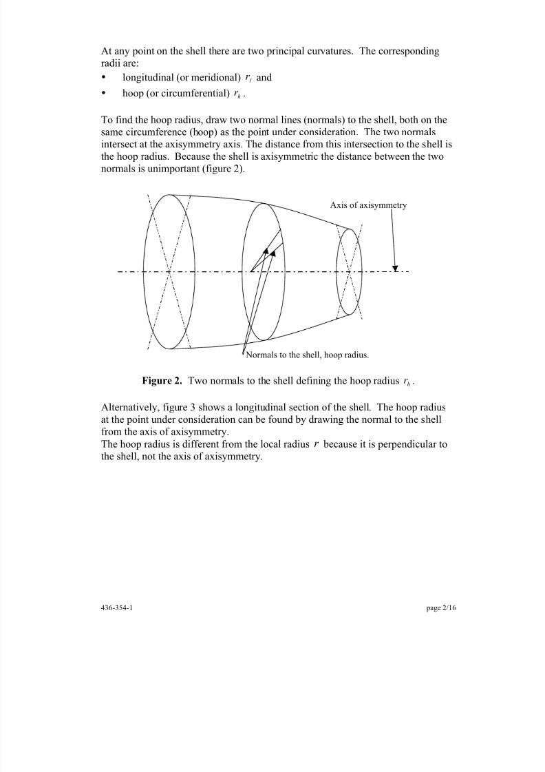
Alternatively, figure 3 shows a longitudinal section of the shell. The hoop radiusat the point under consideration can be found by drawing the normal to the shellfrom the axis of axisymmetry.The hoop radius is different from the local radius r because it is perpendicular tothe shell, not the axis of axisymmetry.
Axis of axisymmetry
Normals to the shell, hoop radius.
8/11/2019 This shells
http://slidepdf.com/reader/full/this-shells 3/16
436-354-1 page 3/16
Figure 3. The difference between hoop radius, hr and local radius, r .
The longitudinal radius is found by drawing two normals to the shell, an
infinitesimal distance apart, with both normals on the same meridian line.Both normal lines will intersect the axis of axisymmetry but will not in generalintersect with each other on the axis of axisymmetry (Figure 4).
Figure 4. The longitudinal radius, lr . Angle l! is also defined.
On a waisted shell (for example, a “classic” coke bottle) it is possible for thelongitudinal radius to be negative.
Axis of axisymmetry
r l
! l
! l
Axis of axis mmetrr h
r
8/11/2019 This shells
http://slidepdf.com/reader/full/this-shells 4/16
436-354-1 page 4/16
Rather than using stresses in the derivation of the defining equations, it isconvenient to introduce the force per unit length of shell:• t N
l l! = is the force per unit length in the longitudinal direction, where t isthe thickness of the shell.
• t N hh ! = is the force per unit length in the hoop direction.
If the shell is spinning then the associated centrifugal load must be considered.This is expressed as a force per unit area of the shell:
g r t r t R /22! " ! # ==
where ! is the density, ! is the angular velocity and ! is the specific weight ofthe shell.
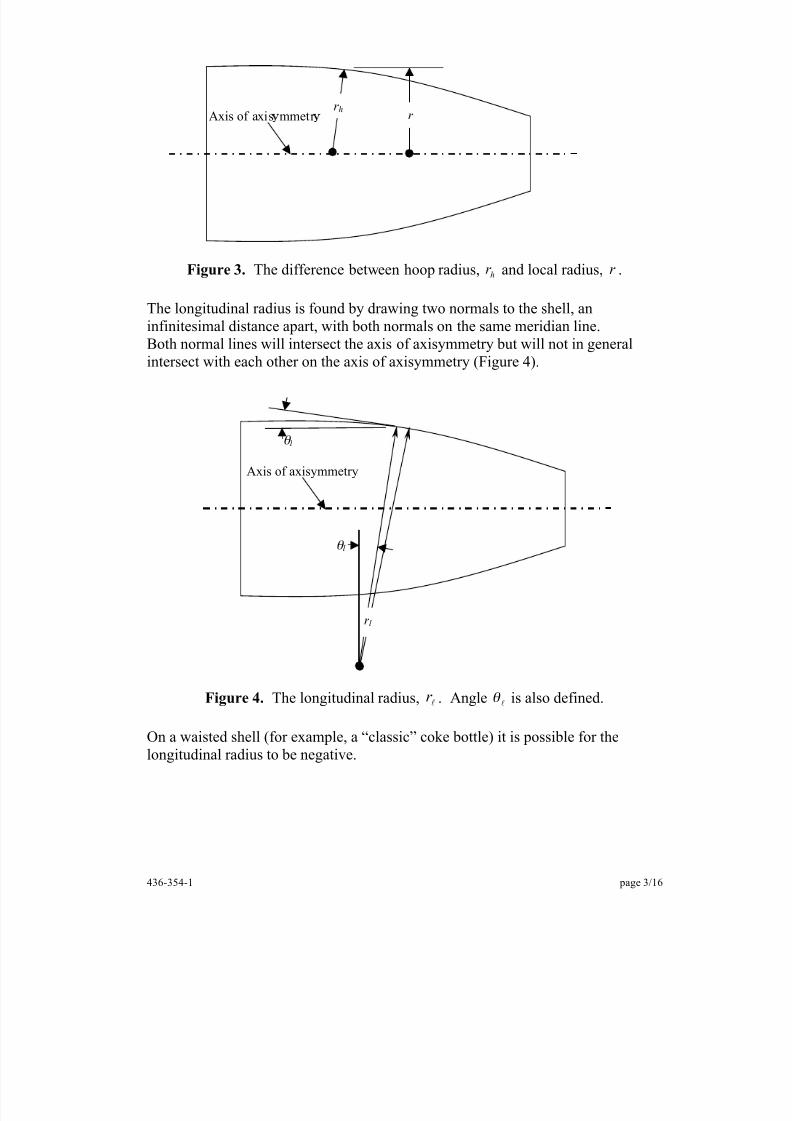
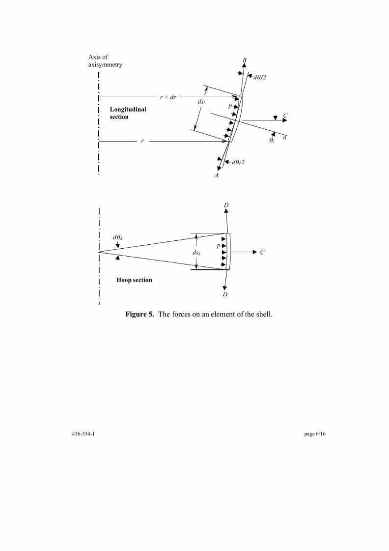
Consider the equilibrium of an infinitesimal element cut from the shell by twomeridians and two circumferences.
The element will have a wedge shape with:• dimension l
ds in the longitudinal direction,• the bottom edge will have dimension hh
d r ds ! = and• the top edge will have dimension ( )h
d dr r ! )+ .The forces on this element are shown in figure 5 and are:
( )
l
l
l
l
l
l
l
ds N D
d dr
r ds RC
d dr r dsds
dN N B
d r N A
h
h
h
h
=
!"#$
%& +=
+!!"
#$$%
&+=
=
'
'
'
2
Summing the forces in the direction n, perpendicular to the shell results in:
( )
0cos2
cos2
222
=!"#$
%& +'
'++!!"
#$$%
&++
ll
lll
l
l
l
l
l
l
l
( (
( ( ( (
( (
(
h
hh
hhh
d dr
r ds R
dsd pr d
ds N d
d dr r dsdsdN
N d
d r N
Substituting lll ! d r ds = and dividing throughout by l
! ! d d h results in:
( ) 0cos2
cos22
=!"#$
%& +''++
!!"#
$$%& ++ llllll
l
l
l
l ( ( dr r Rr prr r N dr r dsdsdN N r N
h
8/11/2019 This shells
http://slidepdf.com/reader/full/this-shells 5/16
436-354-1 page 5/16
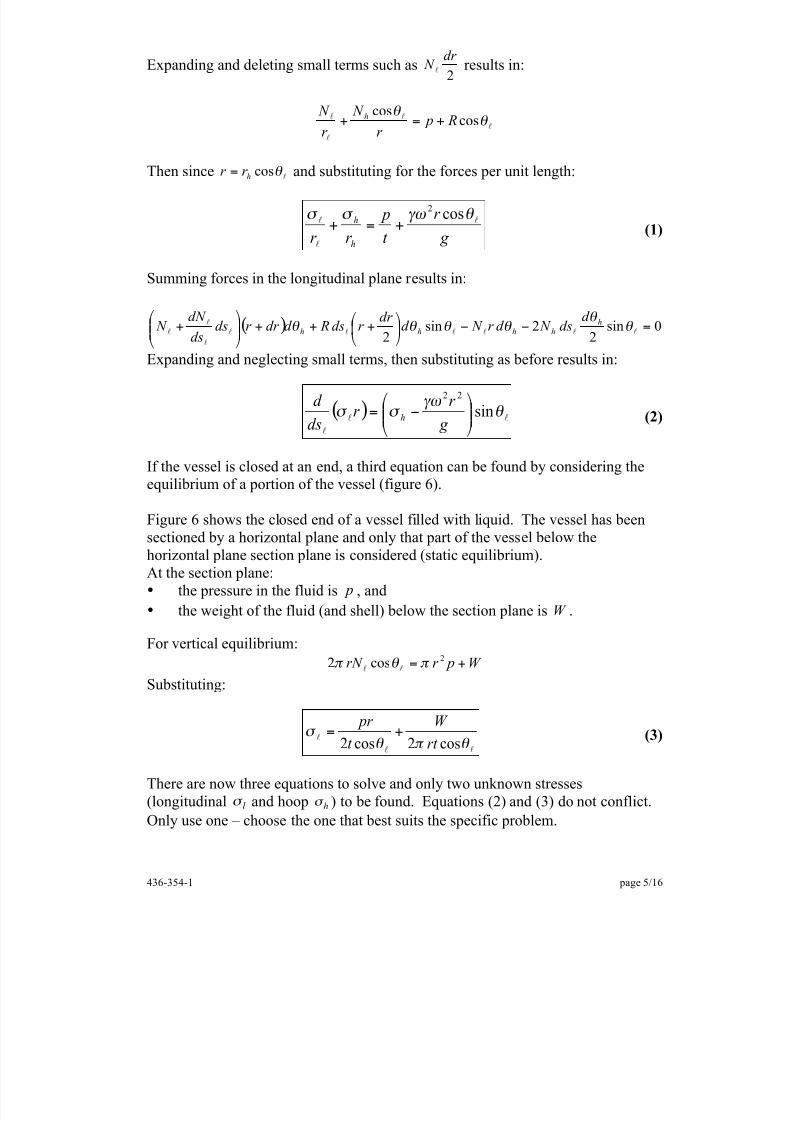
Expanding and deleting small terms such as2
dr N
l results in:
l
l
l
l ! !
coscos
R pr
N r
N h +=+
Then since l! cosh
r r = and substituting for the forces per unit length:
g r
t p
r r h
h l
l
l ! "# $ $ cos2
+=+ (1)
Summing forces in the longitudinal plane results in:
( ) 0sin22sin2 =!!"#$
%&'
+++""#
$%%&
'+ llllll
l
l
l ( (
( ( ( ( h
hhhh
d ds N d r N d
dr r ds Rd dr r dsds
dN N
Expanding and neglecting small terms, then substituting as before results in:
( ) ll
l
! "#
$ $ sin22
%%&
'(()
*+=
g r
r dsd
h (2)
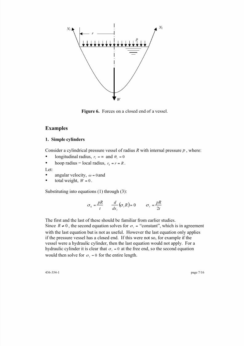
If the vessel is closed at an end, a third equation can be found by considering the
equilibrium of a portion of the vessel (figure 6).
Figure 6 shows the closed end of a vessel filled with liquid. The vessel has beensectioned by a horizontal plane and only that part of the vessel below thehorizontal plane section plane is considered (static equilibrium).At the section plane:• the pressure in the fluid is p , and• the weight of the fluid (and shell) below the section plane is W .
For vertical equilibrium:W pr rN +=
2cos2 ! " ! ll
Substituting:
ll
l! " !
# cos2cos2 rt
W t
pr += (3)
There are now three equations to solve and only two unknown stresses(longitudinal " l and hoop " h ) to be found. Equations (2) and (3) do not conflict.
Only use one – choose the one that best suits the specific problem.
8/11/2019 This shells
http://slidepdf.com/reader/full/this-shells 6/16
436-354-1 page 6/16
Figure 5. The forces on an element of the shell.
pds l
n
Axis ofaxisymmetry
! l
d ! l
/2
d ! l /2
Longitudinalsection
A
B
C
Cdsh p
Hoop section
r
r + dr
D
D
d ! h
8/11/2019 This shells
http://slidepdf.com/reader/full/this-shells 7/16
436-354-1 page 7/16
Figure 6. Forces on a closed end of a vessel.
Examples
1. Simple cylinders
Consider a cylindrical pressure vessel of radius R with internal pressure p , where:• longitudinal radius, !=
lr and 0=
l!
• hoop radius = local radius, Rr r h
== .Let:• angular velocity, 0=! and• total weight, 0=W .
Substituting into equations (1) through (3):
( )t
pR Rdsd
t pR
h 20 === ll
l
! ! !
The first and the last of these should be familiar from earlier studies.Since 0! R , the second equation solves for =
l! “constant”, which is in agreement
with the last equation but is not as useful. However the last equation only appliesif the pressure vessel has a closed end. If this were not so, for example if thevessel were a hydraulic cylinder, then the last equation would not apply. For ahydraulic cylinder it is clear that 0=
l! at the free end, so the second equation
would then solve for 0=
l! for the entire length.
N l N l r
p
W
8/11/2019 This shells
http://slidepdf.com/reader/full/this-shells 8/16
436-354-1 page 8/16
2. Simple spheres
Figure 7: Spherical vessel
For a sphere:• Rr r
h ==
l •
l! cos Rr =
Again, let 0=! and 0=W .
Equation (3) givest
pR2
=
l! .
Substitutingt
pR2
=
l! into equation (1) gives
t pR
h 2=! , as expected.
Equation (2) gives ( )t
PR R
ds
d
2cos =ll
l
! " which is not particularly useful because
there is no obvious way of finding the constant of integration after this result is
integrated.
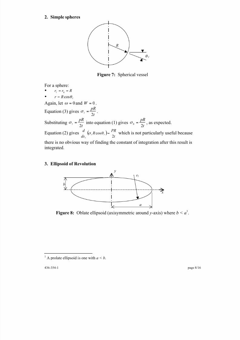
3. Ellipsoid of Revolution
Figure 8: Oblate ellipsoid (axisymmetric around y-axis) where b < a 1.
1 A prolate ellipsoid is one with a < b .
R
! l
r l
a
b
x
y
8/11/2019 This shells
http://slidepdf.com/reader/full/this-shells 9/16
436-354-1 page 9/16
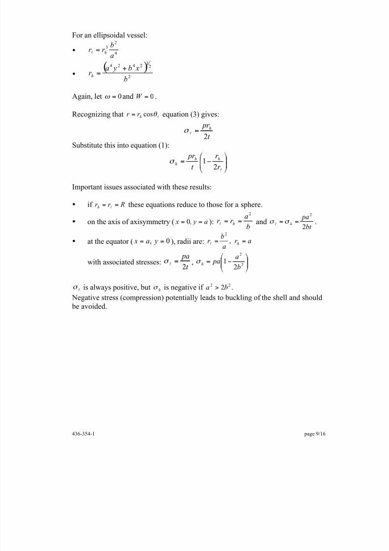
For an ellipsoidal vessel:
• 4
23
a
br r
h=
l
• ( )2
21
2424
b
xb yar h
+=
Again, let 0=! and 0=W .
Recognizing that l! cosh
r r = equation (3) gives:
t pr h
2=
l!
Substitute this into equation (1):
!!"
#$$%
&'
=
lr r
t pr
hhh 21(
Important issues associated with these results:
• if Rr r h
==
l these equations reduce to those for a sphere.
• on the axis of axisymmetry ( a y x == ,0 ):b
ar r
h
2
==
l andbt
pah 2
2
== ! ! l .
• at the equator ( 0, == ya x ), radii are: ar a
br h == ,
2
l
with associated stresses:t
pa2
=
l! , !!"
#$$%
&'=
2
2
21
ba
pah(
l! is always positive, but h! is negative if 22 2 ba > .
Negative stress (compression) potentially leads to buckling of the shell and should be avoided.
8/11/2019 This shells
http://slidepdf.com/reader/full/this-shells 10/16
436-354-1 page 10/16
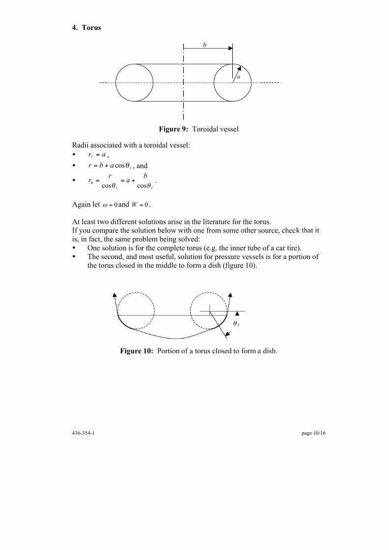
4. Torus
Figure 9: Toroidal vessel
Radii associated with a toroidal vessel:• ar =
l ,•
l! cosabr += , and
• ll
! ! coscos
ba
r r
h +== .
Again let 0=! and 0=W .
At least two different solutions arise in the literature for the torus.If you compare the solution below with one from some other source, check that it
is, in fact, the same problem being solved:• One solution is for the complete torus (e.g. the inner tube of a car tire).• The second, and most useful, solution for pressure vessels is for a portion of
the torus closed in the middle to form a dish (figure 10).
Figure 10: Portion of a torus closed to form a dish.
a
b
! l
8/11/2019 This shells
http://slidepdf.com/reader/full/this-shells 11/16
436-354-1 page 11/16
Equation (3) gives:
l
l!
" cos2 t
pr =
Substituting this into equation (1):
!!"
#$$%
&!"#$
%&'=
2
cos1
2 ( )
ab
t pa
h
Torispherical ends
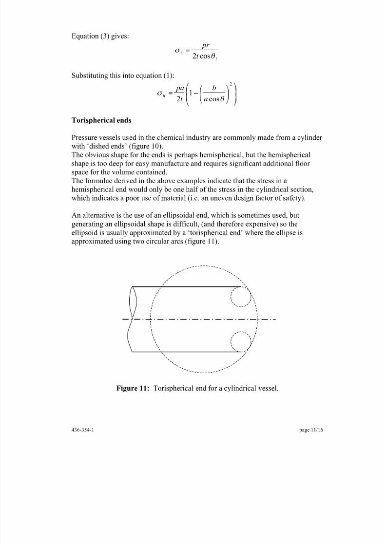
Pressure vessels used in the chemical industry are commonly made from a cylinderwith ‘dished ends’ (figure 10).The obvious shape for the ends is perhaps hemispherical, but the hemisphericalshape is too deep for easy manufacture and requires significant additional floorspace for the volume contained.The formulae derived in the above examples indicate that the stress in ahemispherical end would only be one half of the stress in the cylindrical section,which indicates a poor use of material (i.e. an uneven design factor of safety).
An alternative is the use of an ellipsoidal end, which is sometimes used, butgenerating an ellipsoidal shape is difficult, (and therefore expensive) so theellipsoid is usually approximated by a ‘torispherical end’ where the ellipse isapproximated using two circular arcs (figure 11).
Figure 11: Torispherical end for a cylindrical vessel.
8/11/2019 This shells
http://slidepdf.com/reader/full/this-shells 12/16
8/11/2019 This shells
http://slidepdf.com/reader/full/this-shells 13/16
436-354-1 page 13/16
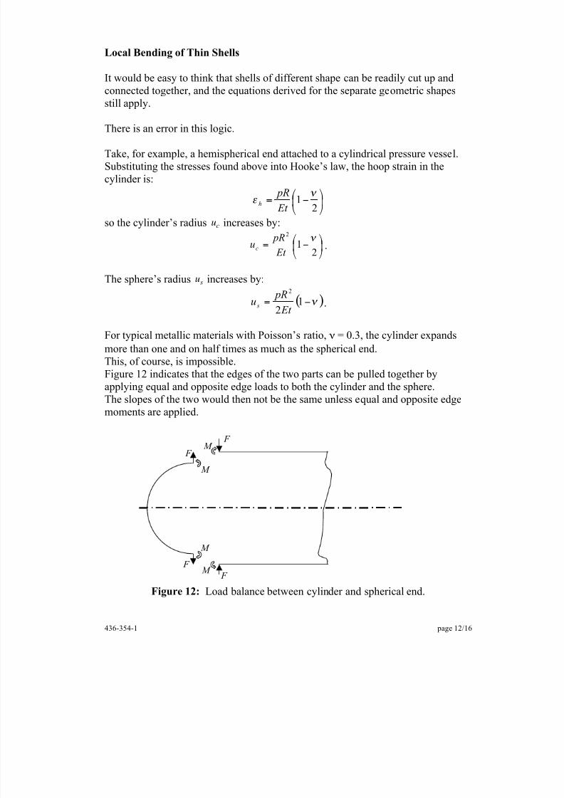
The associated problem is to find:1. the stress distribution in a cylindrical tube with these edge loads, and2. the corresponding stress distribution in a hemisphere.
The overall stress distribution with both pressure and edge loads could then befound by superposition.
The solution of this problem is beyond the scope of these notes but can be found inthe literature.
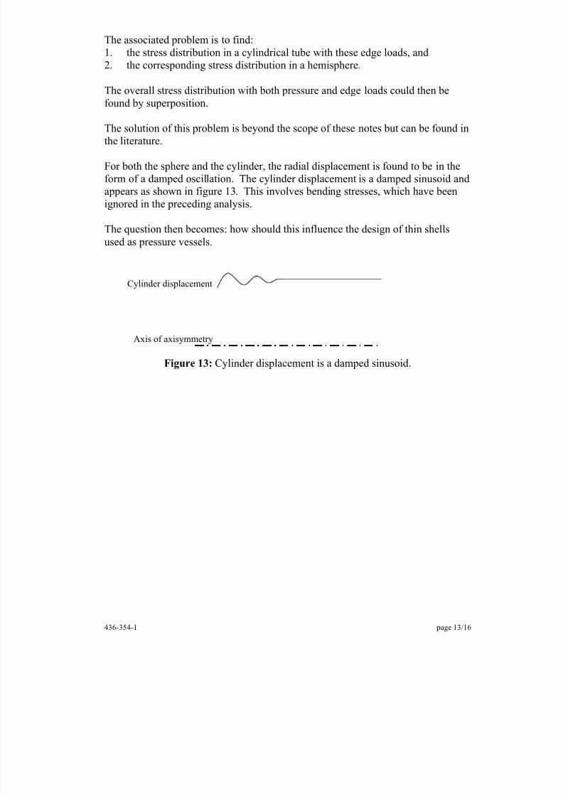
For both the sphere and the cylinder, the radial displacement is found to be in theform of a damped oscillation. The cylinder displacement is a damped sinusoid andappears as shown in figure 13. This involves bending stresses, which have beenignored in the preceding analysis.
The question then becomes: how should this influence the design of thin shellsused as pressure vessels.
Figure 13: Cylinder displacement is a damped sinusoid.
Axis of axisymmetry
Cylinder displacement
8/11/2019 This shells
http://slidepdf.com/reader/full/this-shells 14/16
436-354-1 page 14/16
The rationale for ignoring local bending stresses
Bending stresses add to the stress on one surface of the shell and subtract from thestress on the other surface.
Even if they are relatively large compared with the membrane stresses, the centre
of the shell thickness will have the stress level predicted by thin shell theory.A shell correctly designed according to thin shell theory will, therefore, not exceedthe design stress at the centre of its thickness.
On the other hand, even the yield point may be exceeded on one or other of thesurfaces due to local bending stress.Does this matter?The shell will not leak or explode due to this local yielding.
Suppose a portion of the shell yields in tension under the applied pressure. Whenthe pressure is released that part of the shell will be compressed. If it does notyield in compression before the pressure is reduced to zero, then it will behaveelastically when the pressure is reapplied and the vessel is safe, although there is aquestion of failure due to low cycle fatigue.
If the bending stresses are so large that, when the pressure is released, the materialyields in compression, then it will yield again in tension on the second loading.Repeated yielding with loading and unloading of the shell will cause workhardening, but again, the main issue is that of low cycle fatigue.Fortunately, most industrial pressure vessels execute few load cycles during a lifecycle.
The practical approach to the design and use of thin pressure vessels is as follows:
• The vessel is designed according to thin shell theory and the local bendingstresses are ignored.
• A test pressure is calculated. This is usually based on the maximum pressurelikely to occur in service (usually associated with the safety valve opening
pressure), with a safety allowance and an allowance for the difference inmaterial properties at room temperature and at the working temperature andenvironmental conditions of the shell.
• The vessel is then filled with water and the pressure increased to that test pressure. This may cause local yielding due to the local bending stresses.Vessel welds may be struck with a hammer to check weld soundness.
• In service, the vessel is inspected inside and out on a regular basis, particularly inspecting for cracks in the locations where local bending stresses
would be found.
8/11/2019 This shells
http://slidepdf.com/reader/full/this-shells 15/16
436-354-1 page 15/16
Stiffening Rings
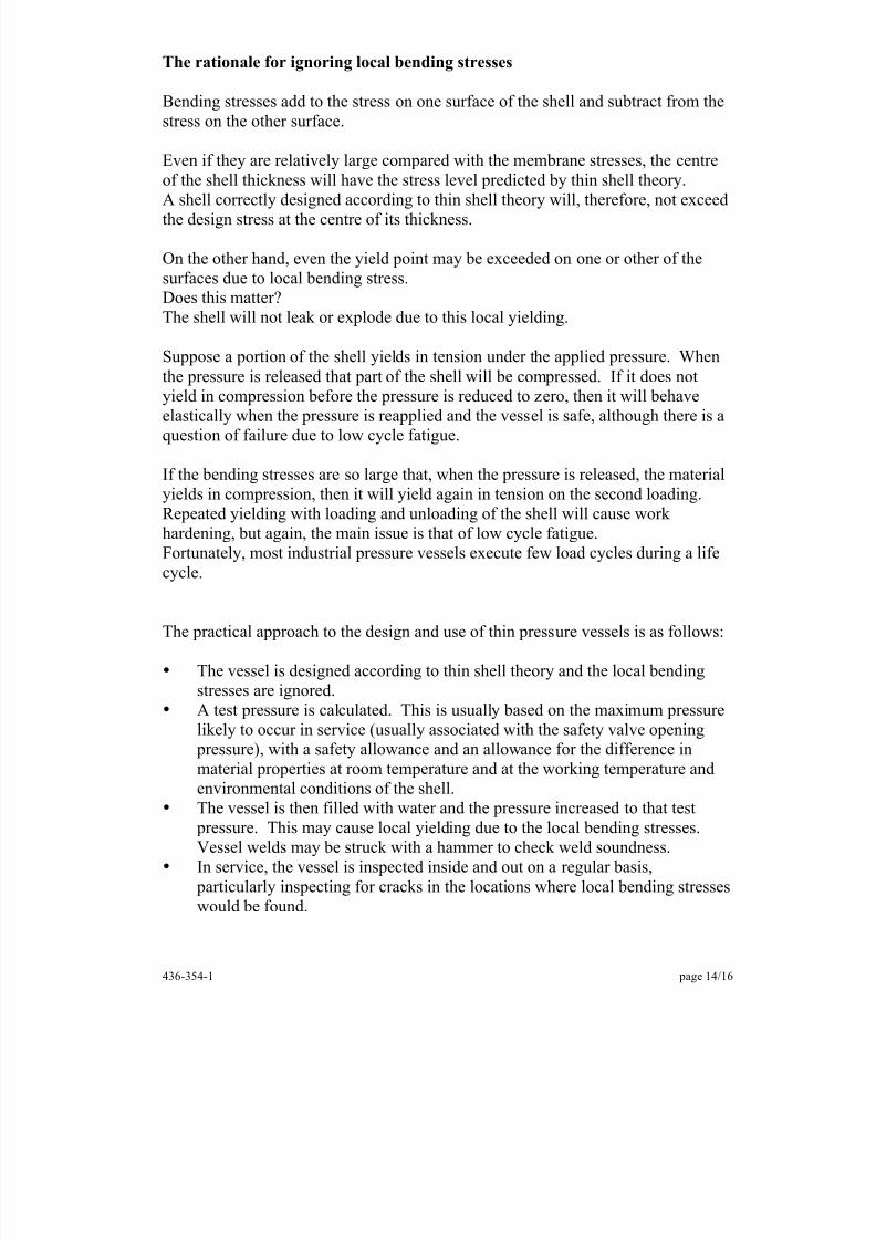
Structures such as grain silos are often built with cylindrical sides and conical bottoms so that the contents can be drained from the bottom.The conical portion of the shell is likely to have a longitudinal stress that has aradial component.
That radial component is applied to the bottom of the cylinder and will introducehoop compression into both components.The shell is likely to buckle at the joint between the two sections.This risk of buckling can be overcome through the inclusion of a ‘stiffening ring’(figure 14).
Figure 14: Silo with conical base and stiffening ring.
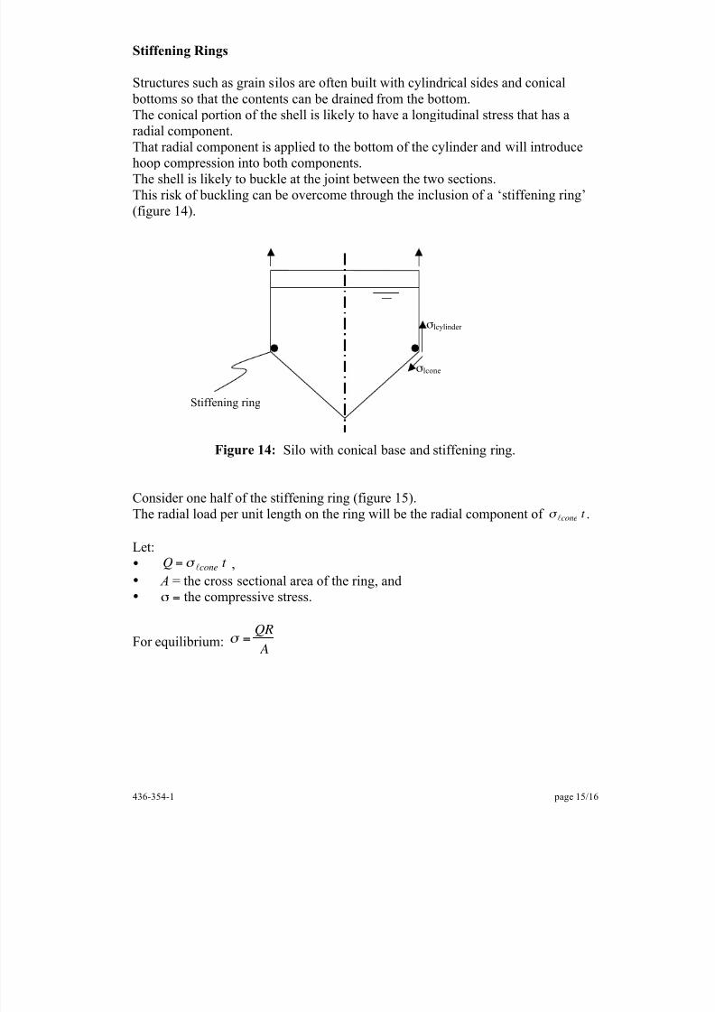
Consider one half of the stiffening ring (figure 15).The radial load per unit length on the ring will be the radial component of " l cone
t .
Let:• Q = " l cone
t ,• A = the cross sectional area of the ring, and• " = the compressive stress.
For equilibrium: " =
QR
A
" lcylinder
" lcone
Stiffening ring
8/11/2019 This shells
http://slidepdf.com/reader/full/this-shells 16/16
436-354-1 page 16/16
Figure 15: Half stiffening ring load equilibrium.
Q
" A " A R


![of use of the elements plates, shells, [] This · planes (modelization plates) or curve (modelization shells). The modelizations of grids intervene for the numerical modelization](https://img.pdfslide.us/doc/110x75/5c12dc2e09d3f2557b8c083e/of-use-of-the-elements-plates-shells-planes-modelization-plates-or-curve.jpg)
![of use of the elements plates, shells, [] This · shells SHB, grids and membranes Summarized: This document is a note of use for the voluminal modelizations plates, shells, shells](https://img.pdfslide.us/doc/110x75/5ee0e005ad6a402d666bf4b1/of-use-of-the-elements-plates-shells-this-shells-shb-grids-and-membranes-summarized.jpg)