Embed Size (px)
Citation preview

NanostructuresDOI: 10.1002/anie.201203456
Diffusion through the Shells of Yolk–Shell and Core–ShellNanostructures in the Liquid Phase**Xiaoliang Liang, Jie Li, Ji Bong Joo, Alejandro Guti!rrez, Aashani Tillekaratne, Ilkeun Lee,Yadong Yin, and Francisco Zaera*
Recent advances in synthetic materials sciences such as theincorporation of self-assembly, sol–gel, and layer-by-layerdeposition chemistry have afforded the development of manyinteresting and potentially useful nanostructures. Amongthose, nanoarchitectures in which a core nanoparticle, oftena transition metal, is encapsulated by an outer layer ofa second material, typically a porous oxide, have gained muchpopularity recently. The shells in these so-called core–shellnanostructures can offer a number of functionalities, includ-ing protection of the core from the outside environment, helpin maintaining its compositional and structural integrity,prevention of the core from aggregating or sintering intolarger particles, selective percolation of molecules in and outof the interior of the shell, increases in solubility and/orbiocompatibility, and addition of new physical or chemicalproperties.[1–3] More sophisticated nanostructures can also besynthesized with a void space, in a yolk–shell or rattle-typenanoarchitecture, to create individualized nanoreactorsaround the core nanoparticles.[4–6] The new properties ofthese nanostructures have already been exploited in sens-ing,[7, 8] drug delivery and biomedical imaging,[9–11] catalysisand electrocatalysis (including fuel cells),[12–14] and the devel-opment of batteries[15] and energy storage devices.[16]
Although many of the applications of the core–shell andyolk–shell nanostructures require the diffusion of molecules
through the outer shell to the core nanoparticle, often theactive phase, surprisingly little work has been reported on thedirect characterization of mass transport across such shells.Only a couple of examples have been reported in the gasphase, where IR absorption spectroscopy has been used toconfirm adsorption of carbon monoxide on the core elementof Pt@CoO[17] and Au@TiO2
[18] yolk–shell samples. Herein wepresent what we believe is the first study on the accessibilityof the core nanoparticles in these types of systems in liquidphase, an environment that is experimentally more difficult toprobe.[19] We have used both carbon monoxide and cincho-nidine in the liquid solvent (carbon tetrachloride) as probes toassess the possible availability of the inner surfaces ofPt@void@TiO2 yolk–shell and Pt@SiO2 core–shell nanostruc-tures.
We first turn our attention to the Pt@void@TiO2 yolk–shell nanostructure, a transmission electron microscopy(TEM) image of which is provided in Figure 1 c. Its perfor-mance was evaluated in contrast with appropriate referencematerials, namely, void@TiO2 hollow shells (Figure 1a),a void@TiO2@SiO2 hollow double-shell nanostructure (Fig-ure 1b), and a regular 1 wt % Pt/TiO2 catalyst prepared by
Figure 1. Transmission electron microscopy (TEM) images of the keysamples studied herein: a) void@TiO2 hollow shells (scale bar50 nm); b) void@TiO2@SiO2 double-shell nanostructures (scale bar100 nm); c) Pt@void@TiO2 yolk–shell nanostructures; andd) Pt@SiO2 core–shell nanostructures.
[*] X. Liang, J. Li, Dr. J. B. Joo, Dr. A. Guti!rrez, Dr. A. Tillekaratne,Dr. I. Lee, Prof. Y. Yin, Prof. F. ZaeraDepartment of Chemistry, University of CaliforniaRiverside, CA 92521 (USA)E-mail: [email protected]: http://www.chem.ucr.edu/groups/Zaera/
X. LiangKey Laboratory of Mineralogy and MetallogenyGuangzhou Institute of GeochemistryChinese Academy of Sciences, Guangzhou 510640 (China)andGraduate University of the Chinese Academy of SciencesBeijing 100049 (China)
Dr. A. Guti!rrezDepartamento de F"sica AplicadaUniversidad Aut#noma de MadridCantoblanco, 28049 Madrid (Spain)
[**] Financial assistance for this project was provided primarily bya grant from the US Department of Energy. Additional funding wasprovided by the US National Science Foundation. X.L. and J.L.acknowledge support from the China Scholarship Council, and A.G.acknowledges financial support from the Spanish Ministerio deEducaci#n.
Supporting information for this article is available on the WWWunder http://dx.doi.org/10.1002/anie.201203456.
.AngewandteCommunications
8034 ! 2012 Wiley-VCH Verlag GmbH & Co. KGaA, Weinheim Angew. Chem. Int. Ed. 2012, 51, 8034 –8036
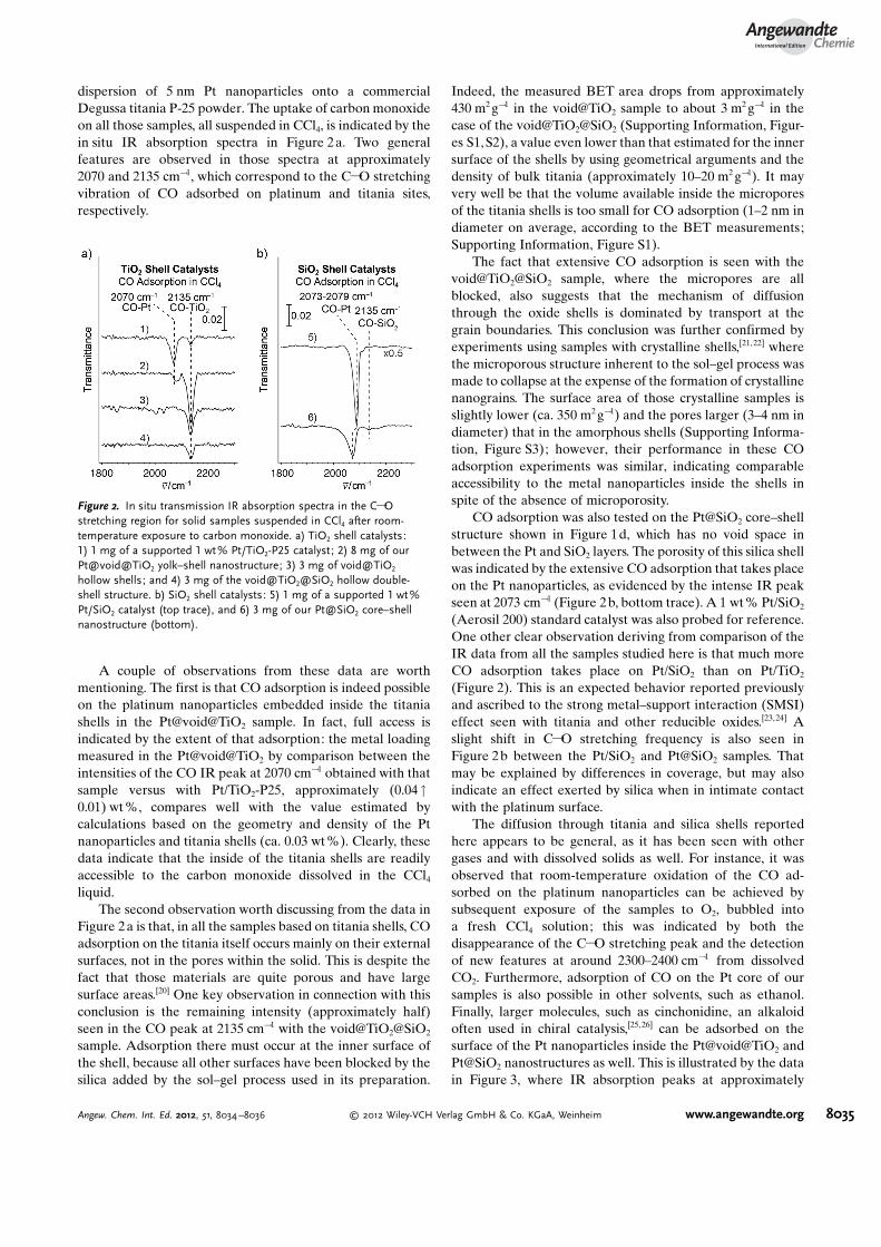
dispersion of 5 nm Pt nanoparticles onto a commercialDegussa titania P-25 powder. The uptake of carbon monoxideon all those samples, all suspended in CCl4, is indicated by thein situ IR absorption spectra in Figure 2a. Two generalfeatures are observed in those spectra at approximately2070 and 2135 cm!1, which correspond to the C!O stretchingvibration of CO adsorbed on platinum and titania sites,respectively.
A couple of observations from these data are worthmentioning. The first is that CO adsorption is indeed possibleon the platinum nanoparticles embedded inside the titaniashells in the Pt@void@TiO2 sample. In fact, full access isindicated by the extent of that adsorption: the metal loadingmeasured in the Pt@void@TiO2 by comparison between theintensities of the CO IR peak at 2070 cm!1 obtained with thatsample versus with Pt/TiO2-P25, approximately (0.04"0.01) wt %, compares well with the value estimated bycalculations based on the geometry and density of the Ptnanoparticles and titania shells (ca. 0.03 wt%). Clearly, thesedata indicate that the inside of the titania shells are readilyaccessible to the carbon monoxide dissolved in the CCl4
liquid.The second observation worth discussing from the data in
Figure 2a is that, in all the samples based on titania shells, COadsorption on the titania itself occurs mainly on their externalsurfaces, not in the pores within the solid. This is despite thefact that those materials are quite porous and have largesurface areas.[20] One key observation in connection with thisconclusion is the remaining intensity (approximately half)seen in the CO peak at 2135 cm!1 with the void@TiO2@SiO2
sample. Adsorption there must occur at the inner surface ofthe shell, because all other surfaces have been blocked by thesilica added by the sol–gel process used in its preparation.
Indeed, the measured BET area drops from approximately430 m2 g!1 in the void@TiO2 sample to about 3 m2 g!1 in thecase of the void@TiO2@SiO2 (Supporting Information, Figur-es S1,S2), a value even lower than that estimated for the innersurface of the shells by using geometrical arguments and thedensity of bulk titania (approximately 10–20 m2 g!1). It mayvery well be that the volume available inside the microporesof the titania shells is too small for CO adsorption (1–2 nm indiameter on average, according to the BET measurements;Supporting Information, Figure S1).
The fact that extensive CO adsorption is seen with thevoid@TiO2@SiO2 sample, where the micropores are allblocked, also suggests that the mechanism of diffusionthrough the oxide shells is dominated by transport at thegrain boundaries. This conclusion was further confirmed byexperiments using samples with crystalline shells,[21,22] wherethe microporous structure inherent to the sol–gel process wasmade to collapse at the expense of the formation of crystallinenanograins. The surface area of those crystalline samples isslightly lower (ca. 350 m2 g!1) and the pores larger (3–4 nm indiameter) that in the amorphous shells (Supporting Informa-tion, Figure S3); however, their performance in these COadsorption experiments was similar, indicating comparableaccessibility to the metal nanoparticles inside the shells inspite of the absence of microporosity.
CO adsorption was also tested on the Pt@SiO2 core–shellstructure shown in Figure 1d, which has no void space inbetween the Pt and SiO2 layers. The porosity of this silica shellwas indicated by the extensive CO adsorption that takes placeon the Pt nanoparticles, as evidenced by the intense IR peakseen at 2073 cm!1 (Figure 2b, bottom trace). A 1 wt % Pt/SiO2
(Aerosil 200) standard catalyst was also probed for reference.One other clear observation deriving from comparison of theIR data from all the samples studied here is that much moreCO adsorption takes place on Pt/SiO2 than on Pt/TiO2
(Figure 2). This is an expected behavior reported previouslyand ascribed to the strong metal–support interaction (SMSI)effect seen with titania and other reducible oxides.[23,24] Aslight shift in C!O stretching frequency is also seen inFigure 2b between the Pt/SiO2 and Pt@SiO2 samples. Thatmay be explained by differences in coverage, but may alsoindicate an effect exerted by silica when in intimate contactwith the platinum surface.
The diffusion through titania and silica shells reportedhere appears to be general, as it has been seen with othergases and with dissolved solids as well. For instance, it wasobserved that room-temperature oxidation of the CO ad-sorbed on the platinum nanoparticles can be achieved bysubsequent exposure of the samples to O2, bubbled intoa fresh CCl4 solution; this was indicated by both thedisappearance of the C!O stretching peak and the detectionof new features at around 2300–2400 cm!1 from dissolvedCO2. Furthermore, adsorption of CO on the Pt core of oursamples is also possible in other solvents, such as ethanol.Finally, larger molecules, such as cinchonidine, an alkaloidoften used in chiral catalysis,[25, 26] can be adsorbed on thesurface of the Pt nanoparticles inside the Pt@void@TiO2 andPt@SiO2 nanostructures as well. This is illustrated by the datain Figure 3, where IR absorption peaks at approximately
Figure 2. In situ transmission IR absorption spectra in the C!Ostretching region for solid samples suspended in CCl4 after room-temperature exposure to carbon monoxide. a) TiO2 shell catalysts:1) 1 mg of a supported 1 wt% Pt/TiO2-P25 catalyst; 2) 8 mg of ourPt@void@TiO2 yolk–shell nanostructure; 3) 3 mg of void@TiO2
hollow shells; and 4) 3 mg of the void@TiO2@SiO2 hollow double-shell structure. b) SiO2 shell catalysts: 5) 1 mg of a supported 1 wt %Pt/SiO2 catalyst (top trace), and 6) 3 mg of our Pt@SiO2 core–shellnanostructure (bottom).
AngewandteChemie
8035Angew. Chem. Int. Ed. 2012, 51, 8034 –8036 ! 2012 Wiley-VCH Verlag GmbH & Co. KGaA, Weinheim www.angewandte.org
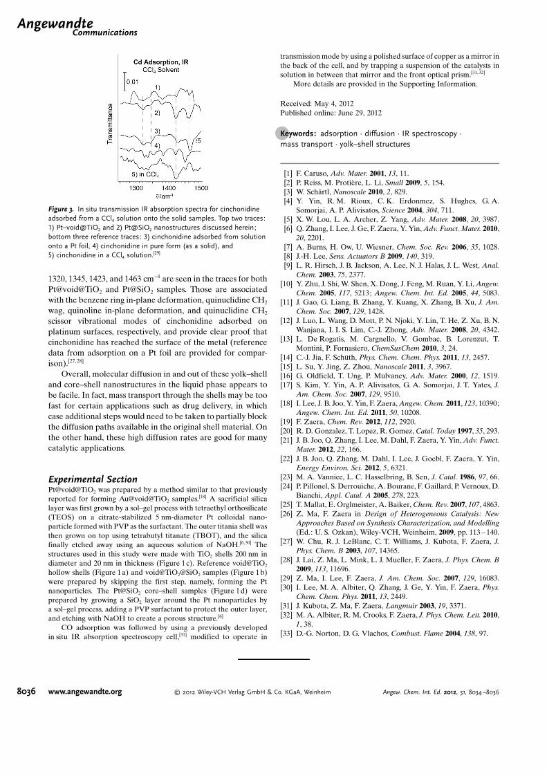
1320, 1345, 1423, and 1463 cm!1 are seen in the traces for bothPt@void@TiO2 and Pt@SiO2 samples. Those are associatedwith the benzene ring in-plane deformation, quinuclidine CH2
wag, quinoline in-plane deformation, and quinuclidine CH2
scissor vibrational modes of cinchonidine adsorbed onplatinum surfaces, respectively, and provide clear proof thatcinchonidine has reached the surface of the metal (referencedata from adsorption on a Pt foil are provided for compar-ison).[27, 28]
Overall, molecular diffusion in and out of these yolk–shelland core–shell nanostructures in the liquid phase appears tobe facile. In fact, mass transport through the shells may be toofast for certain applications such as drug delivery, in whichcase additional steps would need to be taken to partially blockthe diffusion paths available in the original shell material. Onthe other hand, these high diffusion rates are good for manycatalytic applications.
Experimental SectionPt@void@TiO2 was prepared by a method similar to that previouslyreported for forming Au@void@TiO2 samples.[18] A sacrificial silicalayer was first grown by a sol–gel process with tetraethyl orthosilicate(TEOS) on a citrate-stabilized 5 nm-diameter Pt colloidal nano-particle formed with PVP as the surfactant. The outer titania shell wasthen grown on top using tetrabutyl titanate (TBOT), and the silicafinally etched away using an aqueous solution of NaOH.[6,30] Thestructures used in this study were made with TiO2 shells 200 nm indiameter and 20 nm in thickness (Figure 1c). Reference void@TiO2
hollow shells (Figure 1a) and void@TiO2@SiO2 samples (Figure 1b)were prepared by skipping the first step, namely, forming the Ptnanoparticles. The Pt@SiO2 core–shell samples (Figure 1d) wereprepared by growing a SiO2 layer around the Pt nanoparticles bya sol–gel process, adding a PVP surfactant to protect the outer layer,and etching with NaOH to create a porous structure.[6]
CO adsorption was followed by using a previously developedin situ IR absorption spectroscopy cell,[31] modified to operate in
transmission mode by using a polished surface of copper as a mirror inthe back of the cell, and by trapping a suspension of the catalysts insolution in between that mirror and the front optical prism.[31, 32]
More details are provided in the Supporting Information.
Received: May 4, 2012Published online: June 29, 2012
.Keywords: adsorption · diffusion · IR spectroscopy ·mass transport · yolk–shell structures
[1] F. Caruso, Adv. Mater. 2001, 13, 11.[2] P. Reiss, M. Proti!re, L. Li, Small 2009, 5, 154.[3] W. Sch"rtl, Nanoscale 2010, 2, 829.[4] Y. Yin, R. M. Rioux, C. K. Erdonmez, S. Hughes, G. A.
Somorjai, A. P. Alivisatos, Science 2004, 304, 711.[5] X. W. Lou, L. A. Archer, Z. Yang, Adv. Mater. 2008, 20, 3987.[6] Q. Zhang, I. Lee, J. Ge, F. Zaera, Y. Yin, Adv. Funct. Mater. 2010,
20, 2201.[7] A. Burns, H. Ow, U. Wiesner, Chem. Soc. Rev. 2006, 35, 1028.[8] J.-H. Lee, Sens. Actuators B 2009, 140, 319.[9] L. R. Hirsch, J. B. Jackson, A. Lee, N. J. Halas, J. L. West, Anal.
Chem. 2003, 75, 2377.[10] Y. Zhu, J. Shi, W. Shen, X. Dong, J. Feng, M. Ruan, Y. Li, Angew.
Chem. 2005, 117, 5213; Angew. Chem. Int. Ed. 2005, 44, 5083.[11] J. Gao, G. Liang, B. Zhang, Y. Kuang, X. Zhang, B. Xu, J. Am.
Chem. Soc. 2007, 129, 1428.[12] J. Luo, L. Wang, D. Mott, P. N. Njoki, Y. Lin, T. He, Z. Xu, B. N.
Wanjana, I. I. S. Lim, C.-J. Zhong, Adv. Mater. 2008, 20, 4342.[13] L. De Rogatis, M. Cargnello, V. Gombac, B. Lorenzut, T.
Montini, P. Fornasiero, ChemSusChem 2010, 3, 24.[14] C.-J. Jia, F. Sch#th, Phys. Chem. Chem. Phys. 2011, 13, 2457.[15] L. Su, Y. Jing, Z. Zhou, Nanoscale 2011, 3, 3967.[16] G. Oldfield, T. Ung, P. Mulvaney, Adv. Mater. 2000, 12, 1519.[17] S. Kim, Y. Yin, A. P. Alivisatos, G. A. Somorjai, J. T. Yates, J.
Am. Chem. Soc. 2007, 129, 9510.[18] I. Lee, J. B. Joo, Y. Yin, F. Zaera, Angew. Chem. 2011, 123, 10390;
Angew. Chem. Int. Ed. 2011, 50, 10208.[19] F. Zaera, Chem. Rev. 2012, 112, 2920.[20] R. D. Gonzalez, T. Lopez, R. Gomez, Catal. Today 1997, 35, 293.[21] J. B. Joo, Q. Zhang, I. Lee, M. Dahl, F. Zaera, Y. Yin, Adv. Funct.
Mater. 2012, 22, 166.[22] J. B. Joo, Q. Zhang, M. Dahl, I. Lee, J. Goebl, F. Zaera, Y. Yin,
Energy Environ. Sci. 2012, 5, 6321.[23] M. A. Vannice, L. C. Hasselbring, B. Sen, J. Catal. 1986, 97, 66.[24] P. Pillonel, S. Derrouiche, A. Bourane, F. Gaillard, P. Vernoux, D.
Bianchi, Appl. Catal. A 2005, 278, 223.[25] T. Mallat, E. Orglmeister, A. Baiker, Chem. Rev. 2007, 107, 4863.[26] Z. Ma, F. Zaera in Design of Heterogeneous Catalysis: New
Approaches Based on Synthesis Characterization, and Modelling(Ed.: U. S. Ozkan), Wiley-VCH, Weinheim, 2009, pp. 113 – 140.
[27] W. Chu, R. J. LeBlanc, C. T. Williams, J. Kubota, F. Zaera, J.Phys. Chem. B 2003, 107, 14365.
[28] J. Lai, Z. Ma, L. Mink, L. J. Mueller, F. Zaera, J. Phys. Chem. B2009, 113, 11696.
[29] Z. Ma, I. Lee, F. Zaera, J. Am. Chem. Soc. 2007, 129, 16083.[30] I. Lee, M. A. Albiter, Q. Zhang, J. Ge, Y. Yin, F. Zaera, Phys.
Chem. Chem. Phys. 2011, 13, 2449.[31] J. Kubota, Z. Ma, F. Zaera, Langmuir 2003, 19, 3371.[32] M. A. Albiter, R. M. Crooks, F. Zaera, J. Phys. Chem. Lett. 2010,
1, 38.[33] D.-G. Norton, D. G. Vlachos, Combust. Flame 2004, 138, 97.
Figure 3. In situ transmission IR absorption spectra for cinchonidineadsorbed from a CCl4 solution onto the solid samples. Top two traces:1) Pt–void@TiO2 and 2) Pt@SiO2 nanostructures discussed herein;bottom three reference traces: 3) cinchonidine adsorbed from solutiononto a Pt foil, 4) cinchonidine in pure form (as a solid), and5) cinchonidine in a CCl4 solution.[29]
.AngewandteCommunications
8036 www.angewandte.org ! 2012 Wiley-VCH Verlag GmbH & Co. KGaA, Weinheim Angew. Chem. Int. Ed. 2012, 51, 8034 –8036


![of use of the elements plates, shells, [] This · shells SHB, grids and membranes Summarized: This document is a note of use for the voluminal modelizations plates, shells, shells](https://img.pdfslide.us/doc/110x75/5ee0e005ad6a402d666bf4b1/of-use-of-the-elements-plates-shells-this-shells-shb-grids-and-membranes-summarized.jpg)


![Sh - [∫] [∫] She sells sea shells at the sea shore. The shells she sells are surely sea shells. So if she sells shells on the seashore, I'm sure she sells](https://img.pdfslide.us/doc/110x75/56649f165503460f94c2b775/sh-she-sells-sea-shells-at-the-sea-shore-the-shells-she-sells.jpg)