Embed Size (px)
Citation preview
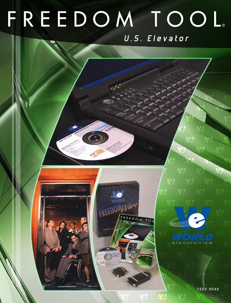
This is Your Software Security Access Key:
DO NOT LOSE IT !
This security device must be plugged into the notebook computer’s USB port or the spare USB port on your interface box whenever the FREEDOM Tool Software is to be run.
List of Trademarks
Windows 3.1, Windows 95, Windows 98, and MS-DOS are registered trademarks/products of Microsoft Corporation.
MP 1220, MP 1230, Ascension 1000, and Ascension 2000 are trademarks of the Thyssen Elevator Corporation (US Elevator Corp).
WORLD electronics, the WORLD electronics' logo, FREEDOM Tool, and FREEDOMWare are registered trademarks of WORLD electronics Sales and Service, Inc.
All other trademarks mentioned in this manual are the sole property of their respective manufacturers.
Copyright © 2000-2007 by WORLD electronics®. All rights reserved. Printed in the United States of America. No part of this publication may be reproduced or distributed in any form or by any means, or stored in a database or retrieval system, without the prior written permission of WORLD electronics. Further, this publication and features described herein are subject to change without notice from the publisher.
Table of Contents:
Introduction: ...........................................................................................................................................1 FREEDOM Tool Features: ..................................................................................................................1 Minimum Hardware and Software Requirements: .......................................................................1 How to contact WORLD electronics: ..............................................................................................2 Package Contents (Hardware Components): .......................................................................................3
US (Ascension) USB Interface Box (7502.9062): ..................................................................................3 Information on connecting to the elevator system: .............................................................................3
Security Key (6015.0014): ......................................................................................................................4 Installation CD (6015.0002): ..................................................................................................................4
Installing the USB US Elevator(Ascension) Software Module: ................................................5 Installing the USB Device Drivers...................................................................................................11
Executing the FREEDOM Tool Shell Program (USB Version): ........................................21 Executing the FREEDOM Tool Shell Program: Parallel Port ONLY!: ...............................24 Getting Started: ...................................................................................................................................26
Starting the US Elevator(Ascension) Software Module - USB: ..............................................26 General Description: .........................................................................................................................29
The Menu ...............................................................................................................................................30 File: .......................................................................................................................................................30 Displays: ...............................................................................................................................................31 Fault Logs: ............................................................................................................................................32
The Windows ........................................................................................................................................33 Displays: ...............................................................................................................................................33 Fault Log: ..............................................................................................................................................36
US Elevator MP 1220 ..........................................................................................................................37 FAULT: ...................................................................................................................................................37 PHASE:...................................................................................................................................................38 MODE: ...................................................................................................................................................38 LEVEL: ..................................................................................................................................................39 DISPLAY: ..............................................................................................................................................39
Display 0: ..............................................................................................................................................39 Display 1: ..............................................................................................................................................41 Display 2: ..............................................................................................................................................43 Display 3: ..............................................................................................................................................45 Display 4: ..............................................................................................................................................47 Display 5: ..............................................................................................................................................49 Display 6: ..............................................................................................................................................51 Display 7: ..............................................................................................................................................53 Display 8: ..............................................................................................................................................55 Display 9: ..............................................................................................................................................56 Display A: .............................................................................................................................................57 Display B: .............................................................................................................................................58 Display C: .............................................................................................................................................59 Display D: .............................................................................................................................................61 Display E: .............................................................................................................................................62
US Elevator MP 1230 ..........................................................................................................................63 FAULT: ...................................................................................................................................................63 PHASE:...................................................................................................................................................64 MODE: ...................................................................................................................................................64 LEVEL: ..................................................................................................................................................65
DISPLAY: ..............................................................................................................................................65 Display 0: ..............................................................................................................................................65 Display 1: ..............................................................................................................................................67 Display 2: ..............................................................................................................................................69 Display 3: ..............................................................................................................................................71 Display 4: ..............................................................................................................................................73 Display 5: ..............................................................................................................................................75 Display 6: ..............................................................................................................................................77 Display 7: ..............................................................................................................................................81 Display 8: ..............................................................................................................................................83
US Elevator Ascension 1000...........................................................................................................84 FAULT: ...................................................................................................................................................84 PHASE:...................................................................................................................................................84 MODE: ...................................................................................................................................................85 LEVEL: ..................................................................................................................................................85 DISPLAY: ..............................................................................................................................................86
Display 0: ..............................................................................................................................................86 Display 1: ..............................................................................................................................................88 Display 2: ..............................................................................................................................................89 Display 3: ..............................................................................................................................................91 Display 4: ..............................................................................................................................................93 Display 5: ..............................................................................................................................................95
US Elevator Ascension 2000...........................................................................................................97 FAULT: ...................................................................................................................................................97 PHASE:...................................................................................................................................................97 MODE: ...................................................................................................................................................97 LEVEL: ..................................................................................................................................................98 DISPLAY: ..............................................................................................................................................98
Display 0: ..............................................................................................................................................99 Display 1: ........................................................................................................................................... 101 Display 2: ........................................................................................................................................... 103 Display 3: ........................................................................................................................................... 105 Display 4: ........................................................................................................................................... 107 Display 5: ........................................................................................................................................... 109 Display 6: ........................................................................................................................................... 110 Display 7: ........................................................................................................................................... 112 Display 8: ........................................................................................................................................... 114 PERSONALITY: ................................................................................................................................ 115
Display 9: ....................................................................................................................................... 116 Display A: ....................................................................................................................................... 120 Display B: ....................................................................................................................................... 121
COUNTER DISPLAY: ....................................................................................................................... 121 Display C: ....................................................................................................................................... 122 Display D: ....................................................................................................................................... 123 Display E: ....................................................................................................................................... 125
FAULT DISPLAY: .............................................................................................................................. 126 Display F (1F through AF): ............................................................................................................. 127
1
Introduction:
The FREEDOM Tool is a sophisticated software tool that allows the operator to service various elevators and elevator control systems. The software allows the operator to simultaneously view independent operations within the elevator system by opening windows to those systems / operations of interest. The selected windows may be left open during the maintenance / repair session and accessed when desired.
This User’s Guide and Reference, part number 7502.9040, has been written to specifically target the Thyssen/US Elevator MP 1220, MP 1230, Ascension 1000, and Ascension 2000 elevator control systems. All references to FREEDOM Tool throughout this manual imply that it pertains solely to the software systems that support the MP 1220, MP 1230, Ascension 1000, and Ascension 2000 elevator control systems.
FREEDOM Tool Features:
The FREEDOM Tool is a Graphical User Interface (GUI) and provides all the functions necessary to service the Thyssen/US Elevator MP 1220, MP 1230, Ascension 1000, and Ascension 2000 elevator control systems. The software runs under the Microsoft Windows operating system and provides the following features:
A Graphical User Interface, representing the adjustment and diagnostic capabilities of the elevator service tool residing within the Thyssen/US Elevator MP 1220, MP 1230, Ascension 1000, and Ascension 2000 elevator control system, makes it easy for the user to learn and adjust the elevator control systems mentioned within this manual.
Simple point and click operations. The computer does all necessary commands for the user in the background.
Minimum Hardware and Software Requirements:
The software is provided as a package by WORLD electronics and is installed on a PC running with Microsoft Windows based Operating systems which have the following characteristics:
A Pentium or equivalent microprocessor.
Windows 98, Windows Me, Windows NT, Windows XP or Windows 2000 Operating System.
CD-ROM Drive
Mouse, Trackball, or other pointing device.
1 USB (Universal Serial Bus) Port
The FREEDOM Tool software is not capable of being executed without a sophisticated security key that is to be connected to the USB port of the computer or the spare USB port on the interface box at the time of the FREEDOM Tool execution. A WORLD electronics “FREEDOM Tool Interface for US Ascension Products” (7502.9062) is required. This interface box provides the proper signal conversions and connections between the computer and the Thyssen/US Elevator MP 1220, MP 1230, Ascension 1000, and Ascension 2000 elevator control system, allowing them to communicate with one another. Older systems may use the Parallel Port based Interface Box for the Ascension software Modules (7502.9036).
2
How to contact WORLD electronics:
If you are having any problems operating the FREEDOM Tool, feel free to contact us at the following location. We value you as a customer and welcome any comments concerning the use of the FREEDOM Tool.
WORLD electronics Phone: 1-800-523-0427 3000 Kutztown Road Phone: (610) 939-9800 Reading, PA 19605-2617 Fax: (610) 939-9895
E-mail:
Elevator Sales: [email protected]
Service: [email protected]
FREEDOM Tool: [email protected]
When calling WORLD electronics for assistance, have your product serial number, the model computer being used, operating system type, and the error description ready.
3
Package Contents (Hardware Components):
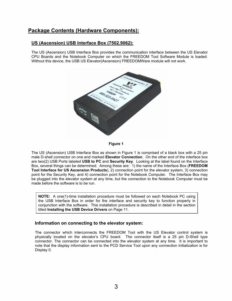
US (Ascension) USB Interface Box (7502.9062):
The US (Ascension) USB Interface Box provides the communication interface between the US Elevator CPU Boards and the Notebook Computer on which the FREEDOM Tool Software Module is loaded. Without this device, the USB US Elevator(Ascension) FREEDOMWare module will not work.
Figure 1
The US (Ascension) USB Interface Box as shown in Figure 1 is comprised of a black box with a 25 pin male D-shell connector on one end marked Elevator Connection. On the other end of the interface box are two(2) USB Ports labeled USB to PC and Security Key. Looking at the label found on the Interface Box, several things can be determined. Among these are: 1) the name of the Interface Box (FREEDOM Tool Interface for US Ascension Products), 2) connection point for the elevator system, 3) connection point for the Security Key, and 4) connection point for the Notebook Computer. The Interface Box may be plugged into the elevator system at any time, but the connection to the Notebook Computer must be made before the software is to be run.
NOTE: A one(1)-time installation procedure must be followed on each Notebook PC using the USB Interface Box in order for the interface and security key to function properly in conjunction with the software. This installation procedure is described in detail in the section titled Installing the USB Device Drivers on Page 11.
Information on connecting to the elevator system:
The connector which interconnects the FREEDOM Tool with the US Elevator control system is physically located on the elevator’s CPU board. The connector itself is a 25 pin D-Shell type connector. The connector can be connected into the elevator system at any time. It is important to note that the display information sent to the PCD Service Tool upon any connection initialization is for Display 0.
4
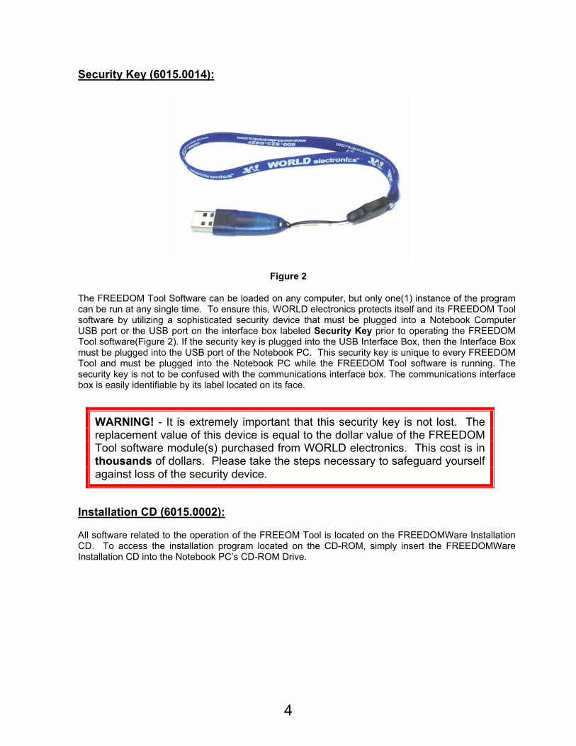
Security Key (6015.0014):
Figure 2
The FREEDOM Tool Software can be loaded on any computer, but only one(1) instance of the program can be run at any single time. To ensure this, WORLD electronics protects itself and its FREEDOM Tool software by utilizing a sophisticated security device that must be plugged into a Notebook Computer USB port or the USB port on the interface box labeled Security Key prior to operating the FREEDOM Tool software(Figure 2). If the security key is plugged into the USB Interface Box, then the Interface Box must be plugged into the USB port of the Notebook PC. This security key is unique to every FREEDOM Tool and must be plugged into the Notebook PC while the FREEDOM Tool software is running. The security key is not to be confused with the communications interface box. The communications interface box is easily identifiable by its label located on its face.
WARNING! - It is extremely important that this security key is not lost. The replacement value of this device is equal to the dollar value of the FREEDOM Tool software module(s) purchased from WORLD electronics. This cost is in thousands of dollars. Please take the steps necessary to safeguard yourself against loss of the security device.
Installation CD (6015.0002):
All software related to the operation of the FREEOM Tool is located on the FREEDOMWare Installation CD. To access the installation program located on the CD-ROM, simply insert the FREEDOMWare Installation CD into the Notebook PC’s CD-ROM Drive.
5
Figure 3
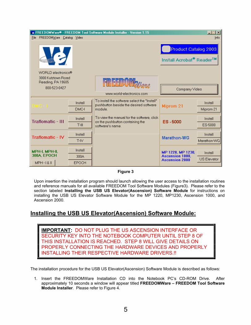
Upon insertion the installation program should launch allowing the user access to the installation routines and reference manuals for all available FREEDOM Tool Software Modules (Figure3). Please refer to the section labeled Installing the USB US Elevator(Ascension) Software Module for instructions on installing the USB US Elevator Software Module for the MP 1220, MP1230, Ascension 1000, and Ascension 2000.
Installing the USB US Elevator(Ascension) Software Module:
IMPORTANT: DO NOT PLUG THE US ASCENSION INTERFACE OR SECURITY KEY INTO THE NOTEBOOK COMPUTER UNTIL STEP 8 OF THIS INSTALLATION IS REACHED. STEP 8 WILL GIVE DETAILS ON PROPERLY CONNECTING THE HARDWARE DEVICES AND PROPERLY INSTALLING THEIR RESPECTIVE HARDWARE DRIVERS.!!
The installation procedure for the USB US Elevator(Ascension) Software Module is described as follows:
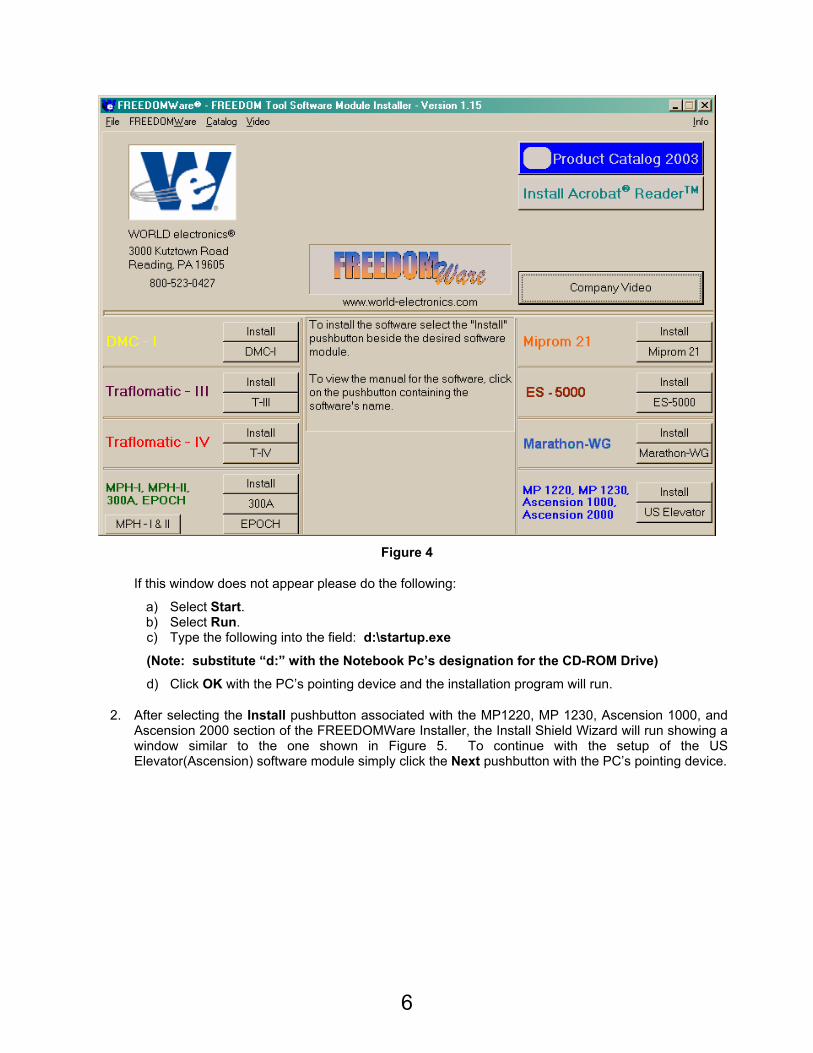
1. Insert the FREEDOMWare Installation CD into the Notebook PC’s CD-ROM Drive. After approximately 10 seconds a window will appear titled FREEDOMWare – FREEDOM Tool Software Module Installer. Please refer to Figure 4.
6
Figure 4
If this window does not appear please do the following:
a) Select Start. b) Select Run. c) Type the following into the field: d:\startup.exe
(Note: substitute “d:” with the Notebook Pc’s designation for the CD-ROM Drive)
d) Click OK with the PC’s pointing device and the installation program will run.
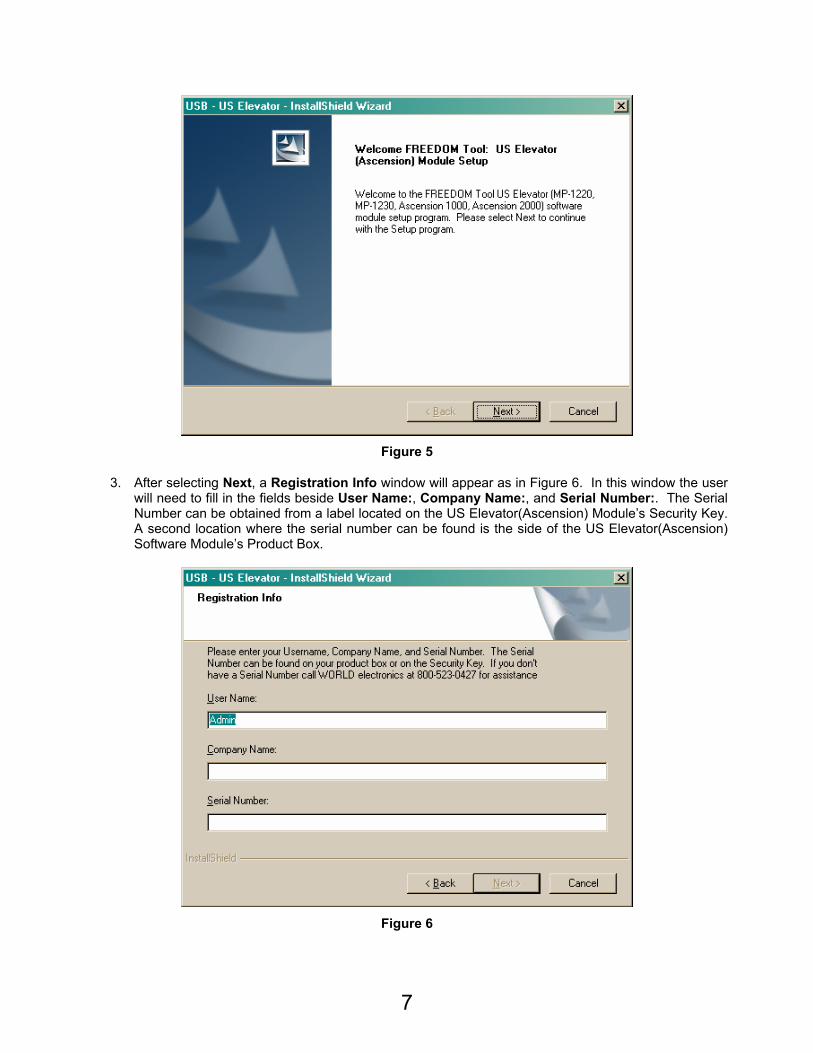
2. After selecting the Install pushbutton associated with the MP1220, MP 1230, Ascension 1000, and Ascension 2000 section of the FREEDOMWare Installer, the Install Shield Wizard will run showing a window similar to the one shown in Figure 5. To continue with the setup of the US Elevator(Ascension) software module simply click the Next pushbutton with the PC’s pointing device.
7
Figure 5
3. After selecting Next, a Registration Info window will appear as in Figure 6. In this window the user will need to fill in the fields beside User Name:, Company Name:, and Serial Number:. The Serial Number can be obtained from a label located on the US Elevator(Ascension) Module’s Security Key. A second location where the serial number can be found is the side of the US Elevator(Ascension) Software Module’s Product Box.
Figure 6
8
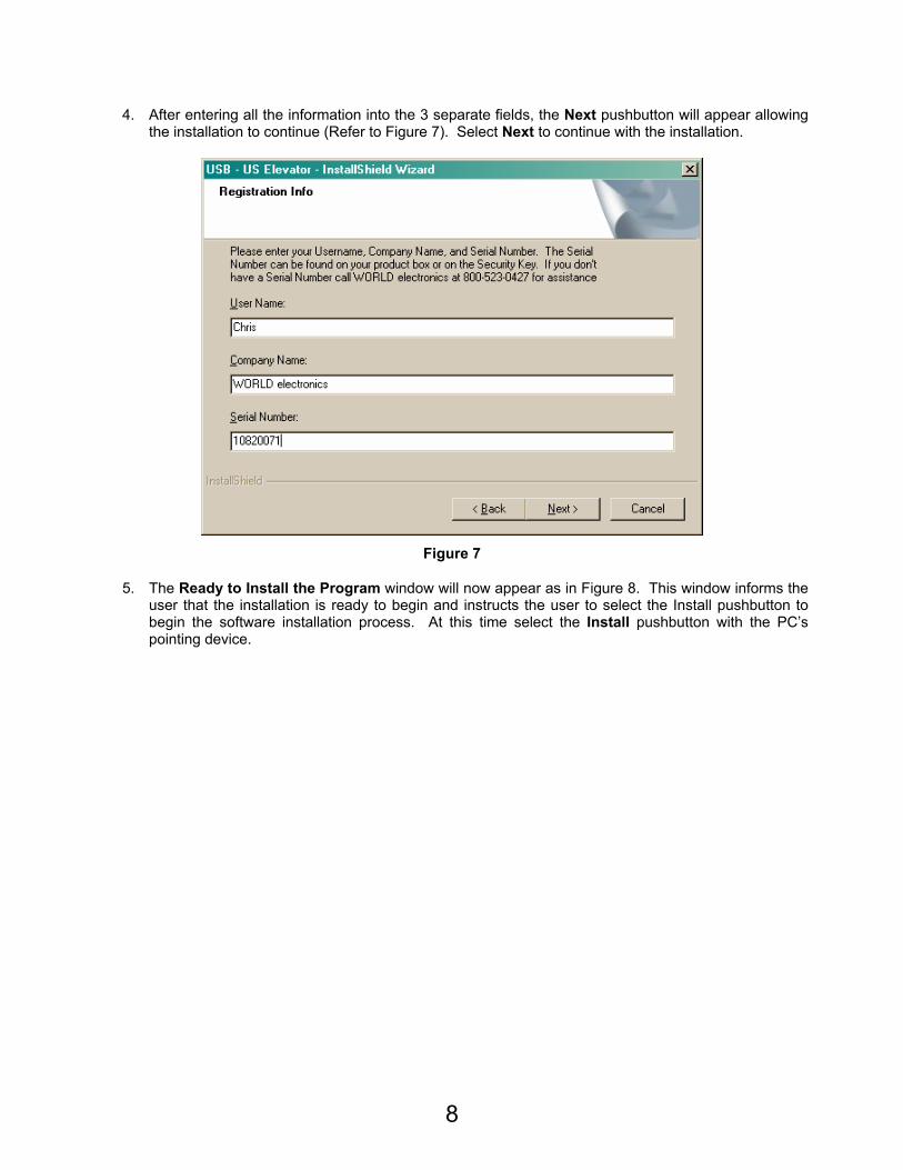
4. After entering all the information into the 3 separate fields, the Next pushbutton will appear allowing the installation to continue (Refer to Figure 7). Select Next to continue with the installation.
Figure 7
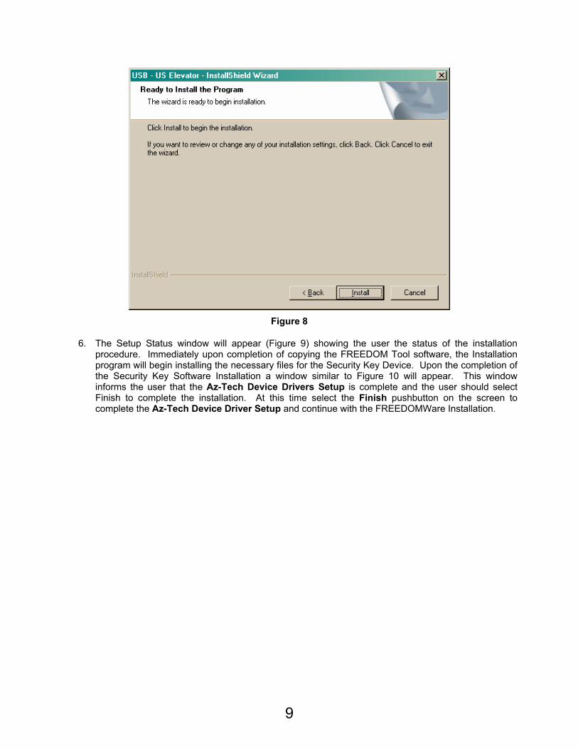
5. The Ready to Install the Program window will now appear as in Figure 8. This window informs the user that the installation is ready to begin and instructs the user to select the Install pushbutton to begin the software installation process. At this time select the Install pushbutton with the PC’s pointing device.
9
Figure 8
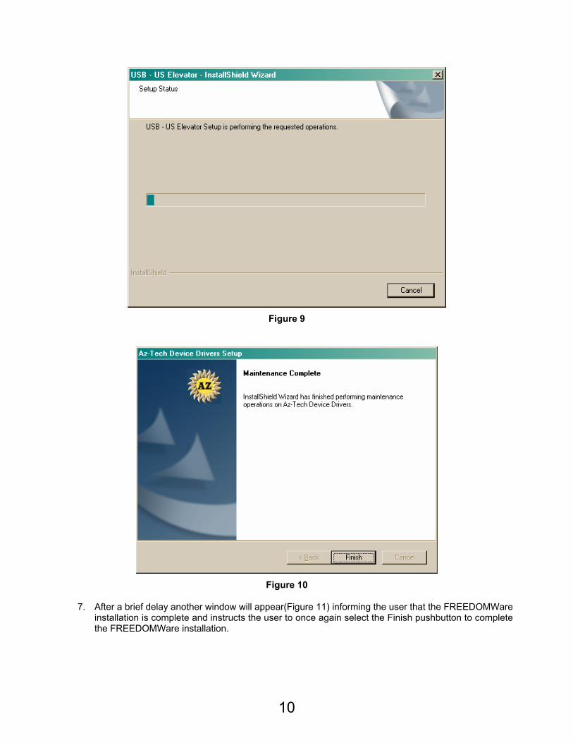
6. The Setup Status window will appear (Figure 9) showing the user the status of the installation procedure. Immediately upon completion of copying the FREEDOM Tool software, the Installation program will begin installing the necessary files for the Security Key Device. Upon the completion of the Security Key Software Installation a window similar to Figure 10 will appear. This window informs the user that the Az-Tech Device Drivers Setup is complete and the user should select Finish to complete the installation. At this time select the Finish pushbutton on the screen to complete the Az-Tech Device Driver Setup and continue with the FREEDOMWare Installation.
10
Figure 9
Figure 10
7. After a brief delay another window will appear(Figure 11) informing the user that the FREEDOMWare installation is complete and instructs the user to once again select the Finish pushbutton to complete the FREEDOMWare installation.
11
Figure 11
Installing the USB Device Drivers
1. AT THIS TIME PLUG THE US (ASCENSION) USB INTERFACE BOX INTO THE USB PORT ON THE NOTEBOOK PC. DO NOT PLUG THE USB SECURITY KEY INTO ANY PORT (INCLUDING THE ONE LOCATED ON THE USB INTERFACE BOX) AT THIS TIME.
2. A Found New Hardware Wizard window should appear. See Figure 12. In this window click, one time, on the circle beside No, not this time. The Circle should have a Black Dot in its center. Click the Next pushbutton to continue.
12
Figure 12
3. The window shown in Figure 13 should appear. In this window, click one time on the circle beside Install from a list or specific location (Advanced) so that it has a black dot in its center. After completing this task, select Next to continue with the Driver Installation.
Figure 13
4. After selecting list or specific location, the New Hardware Wizard window will appear as seen in Figure 14. In Figure 14, the user must make sure the following items are selected with a black dot or check mark: Search for the best driver in these locations, Include this location in the search:. When Include this location in the search: is checked the pushbutton labeled Browse should be
13
enabled. At this time select the Browse pushbutton with the PC’s pointing device.
Figure 14
5. When the Browse pushbutton is selected, a Browse for Folder will appear as in Figure 15. Do the following in this window:
a) Click on My Computer. b) Click on Local Disk (C: ). c) Click on Nellie. d) Click on SiLabs. e) Click on MCU. f) Click on Cp210x. g) Click on WIN. h) Click on OK pushbutton.
14
Figure 15
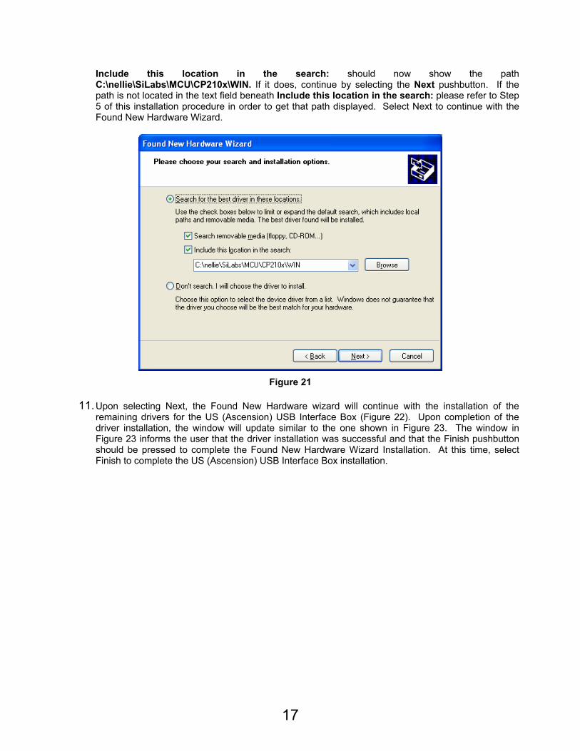
6. After the OK pushbutton is selected in the Browse For Folder window, the input focus will once again be upon the Found New Hardware Wizard window requesting the user to choose the search and installation options. Looking at the field underneath Include this location in the search: should be the directory path: C:\nellie\SiLabs\MCU\CP210x\WIN. Refer to Figure 16. To continue, press the Next pushbutton found at the bottom of this window.
Figure 16
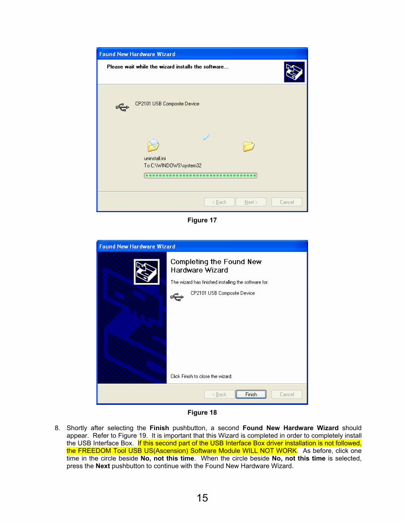
7. The Wizard will look for the necessary drivers for the CP2102 USB to UART Bridge Controller and Install them (See Figure 17). When the installation is complete and successful the Completing the Found New Hardware Wizard will appear (Figure 18) showing the user the installation status. Click the Finish pushbutton to complete the installation.
15
Figure 17
Figure 18
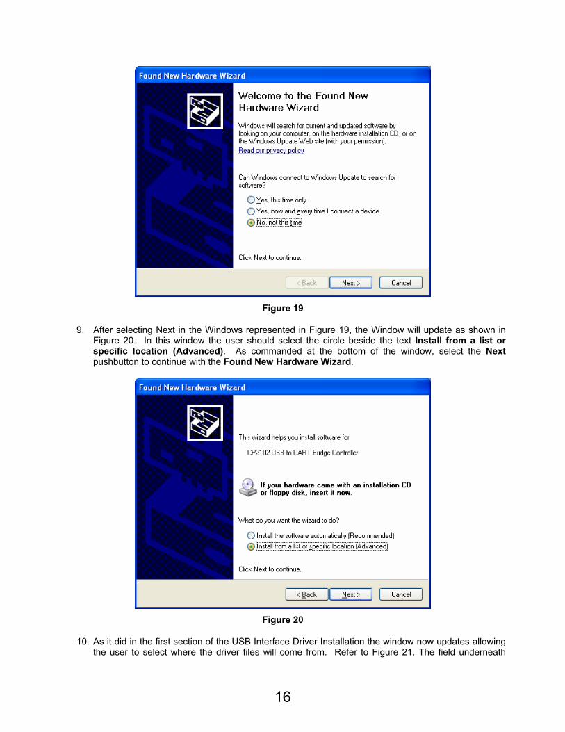
8. Shortly after selecting the Finish pushbutton, a second Found New Hardware Wizard should appear. Refer to Figure 19. It is important that this Wizard is completed in order to completely install the USB Interface Box. If this second part of the USB Interface Box driver installation is not followed, the FREEDOM Tool USB US(Ascension) Software Module WILL NOT WORK. As before, click one time in the circle beside No, not this time. When the circle beside No, not this time is selected, press the Next pushbutton to continue with the Found New Hardware Wizard.
16
Figure 19
9. After selecting Next in the Windows represented in Figure 19, the Window will update as shown in Figure 20. In this window the user should select the circle beside the text Install from a list or specific location (Advanced). As commanded at the bottom of the window, select the Next pushbutton to continue with the Found New Hardware Wizard.
Figure 20
10. As it did in the first section of the USB Interface Driver Installation the window now updates allowing the user to select where the driver files will come from. Refer to Figure 21. The field underneath
17
Include this location in the search: should now show the path C:\nellie\SiLabs\MCU\CP210x\WIN. If it does, continue by selecting the Next pushbutton. If the path is not located in the text field beneath Include this location in the search: please refer to Step 5 of this installation procedure in order to get that path displayed. Select Next to continue with the Found New Hardware Wizard.
Figure 21
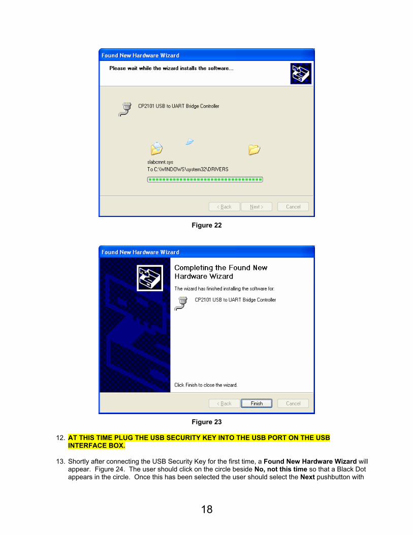
11. Upon selecting Next, the Found New Hardware wizard will continue with the installation of the remaining drivers for the US (Ascension) USB Interface Box (Figure 22). Upon completion of the driver installation, the window will update similar to the one shown in Figure 23. The window in Figure 23 informs the user that the driver installation was successful and that the Finish pushbutton should be pressed to complete the Found New Hardware Wizard Installation. At this time, select Finish to complete the US (Ascension) USB Interface Box installation.
18
Figure 22
Figure 23
12. AT THIS TIME PLUG THE USB SECURITY KEY INTO THE USB PORT ON THE USB INTERFACE BOX.
13. Shortly after connecting the USB Security Key for the first time, a Found New Hardware Wizard will appear. Figure 24. The user should click on the circle beside No, not this time so that a Black Dot appears in the circle. Once this has been selected the user should select the Next pushbutton with
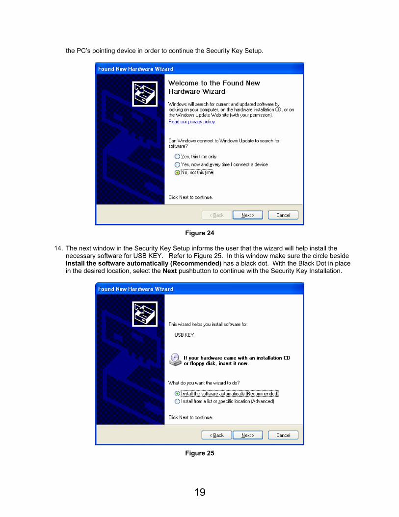
19
the PC’s pointing device in order to continue the Security Key Setup.
Figure 24
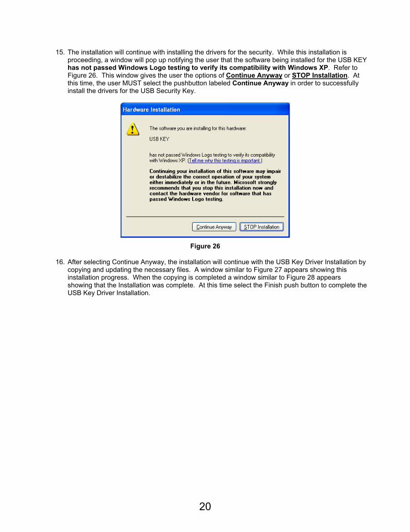
14. The next window in the Security Key Setup informs the user that the wizard will help install the necessary software for USB KEY. Refer to Figure 25. In this window make sure the circle beside Install the software automatically (Recommended) has a black dot. With the Black Dot in place in the desired location, select the Next pushbutton to continue with the Security Key Installation.
Figure 25
20
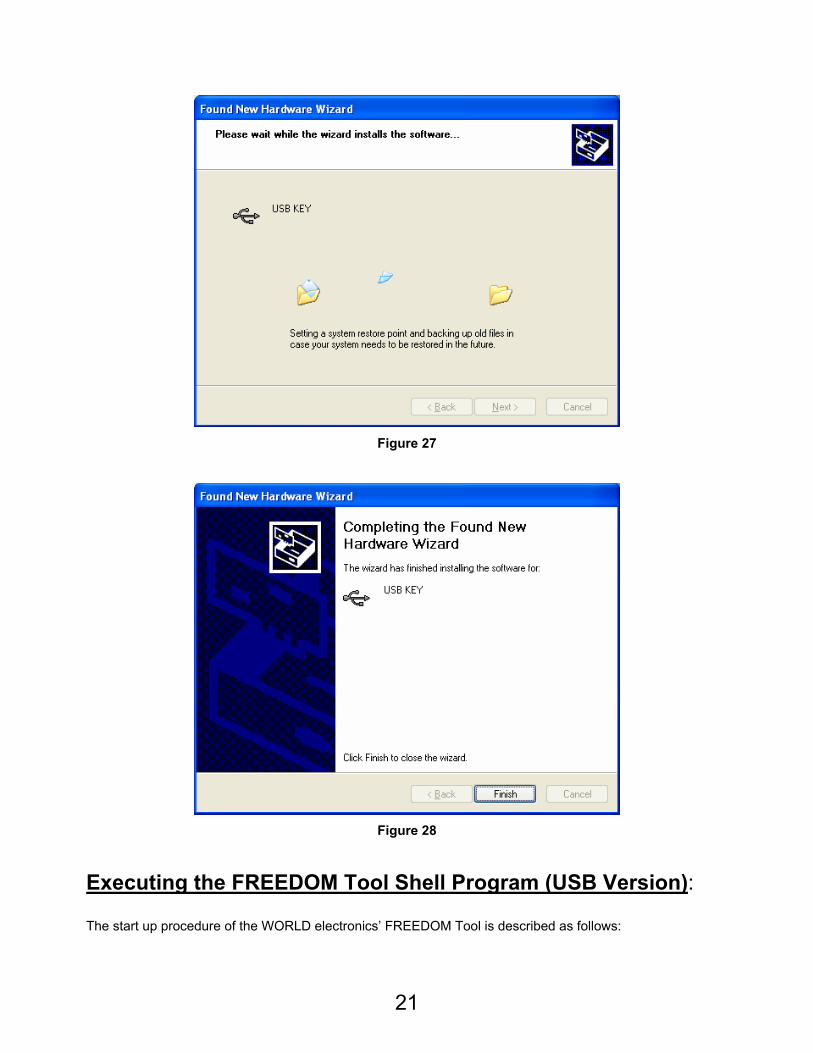
15. The installation will continue with installing the drivers for the security. While this installation is proceeding, a window will pop up notifying the user that the software being installed for the USB KEY has not passed Windows Logo testing to verify its compatibility with Windows XP. Refer to Figure 26. This window gives the user the options of Continue Anyway or STOP Installation. At this time, the user MUST select the pushbutton labeled Continue Anyway in order to successfully install the drivers for the USB Security Key.
Figure 26
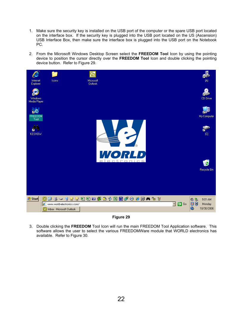
16. After selecting Continue Anyway, the installation will continue with the USB Key Driver Installation by copying and updating the necessary files. A window similar to Figure 27 appears showing this installation progress. When the copying is completed a window similar to Figure 28 appears showing that the Installation was complete. At this time select the Finish push button to complete the USB Key Driver Installation.
21
Figure 27
Figure 28
Executing the FREEDOM Tool Shell Program (USB Version):
The start up procedure of the WORLD electronics’ FREEDOM Tool is described as follows:
22
1. Make sure the security key is installed on the USB port of the computer or the spare USB port located on the interface box. If the security key is plugged into the USB port located on the US (Ascension) USB Interface Box, then make sure the interface box is plugged into the USB port on the Notebook PC.
2. From the Microsoft Windows Desktop Screen select the FREEDOM Tool Icon by using the pointing device to position the cursor directly over the FREEDOM Tool Icon and double clicking the pointing device button. Refer to Figure 29.
Figure 29
3. Double clicking the FREEDOM Tool Icon will run the main FREEDOM Tool Application software. This software allows the user to select the various FREEDOMWare module that WORLD electronics has available. Refer to Figure 30.
23
Figure 30
NOTE: Only installed FREEDOMWare software will run. If the module selected is not installed a window will appear as in Figure 31 informing the user that the Module is not installed and to contact WORLD electronics. If this window appears and the software was purchased from WORLD electronics, then contact a member of WORLD electronics’ technical support staff. If the software was not purchased, it can be purchased by contacting WORLD electronics’ Sales Staff. The contact information on both of these departments can be found on Page 2 of this manual.
Figure 31
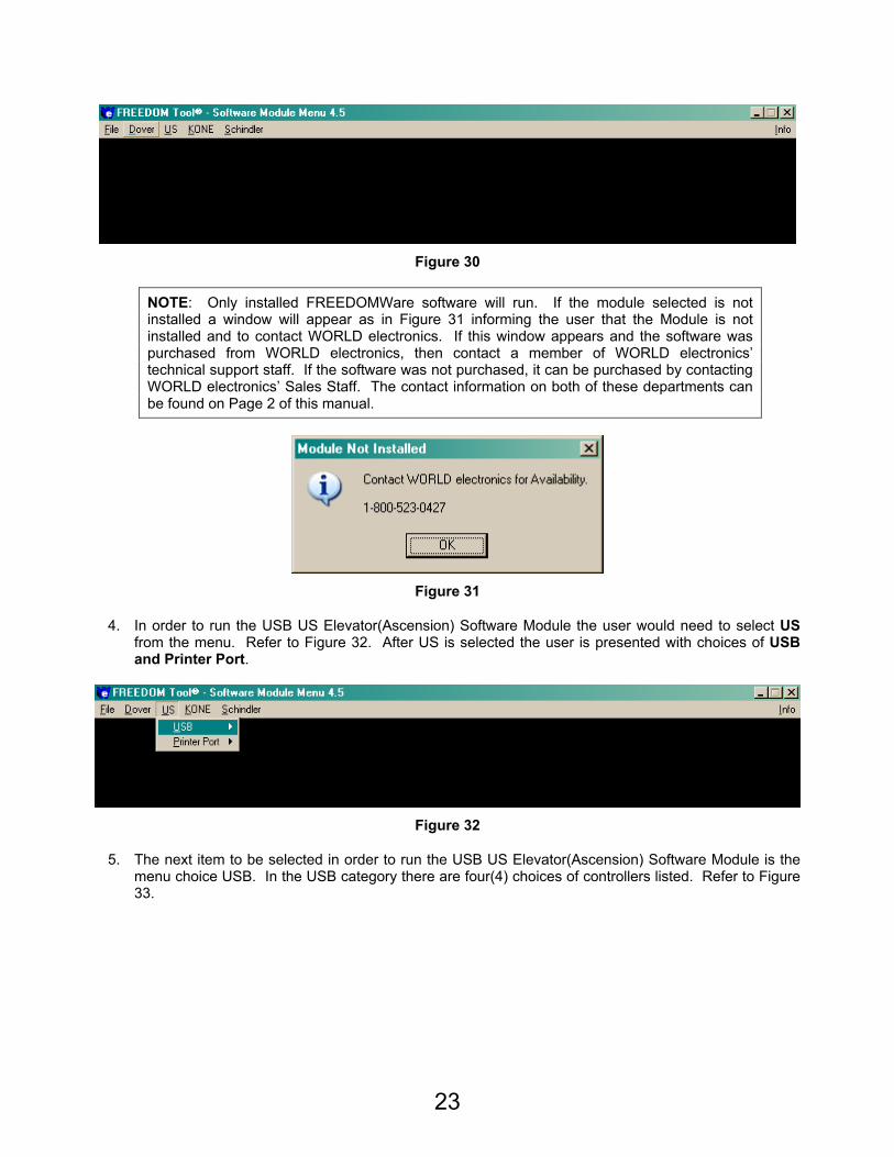
4. In order to run the USB US Elevator(Ascension) Software Module the user would need to select US from the menu. Refer to Figure 32. After US is selected the user is presented with choices of USB and Printer Port.
Figure 32
5. The next item to be selected in order to run the USB US Elevator(Ascension) Software Module is the menu choice USB. In the USB category there are four(4) choices of controllers listed. Refer to Figure 33.
24
Figure 33
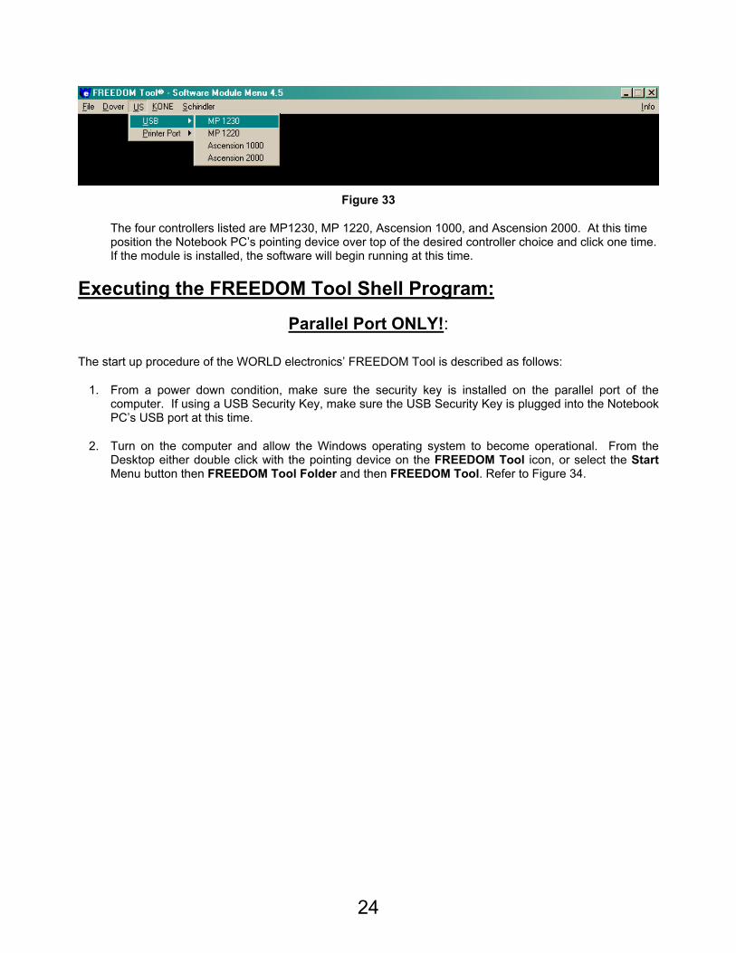
The four controllers listed are MP1230, MP 1220, Ascension 1000, and Ascension 2000. At this time position the Notebook PC’s pointing device over top of the desired controller choice and click one time. If the module is installed, the software will begin running at this time.
Executing the FREEDOM Tool Shell Program:
Parallel Port ONLY!:
The start up procedure of the WORLD electronics’ FREEDOM Tool is described as follows:
1. From a power down condition, make sure the security key is installed on the parallel port of the computer. If using a USB Security Key, make sure the USB Security Key is plugged into the Notebook PC’s USB port at this time.
2. Turn on the computer and allow the Windows operating system to become operational. From the Desktop either double click with the pointing device on the FREEDOM Tool icon, or select the Start Menu button then FREEDOM Tool Folder and then FREEDOM Tool. Refer to Figure 34.
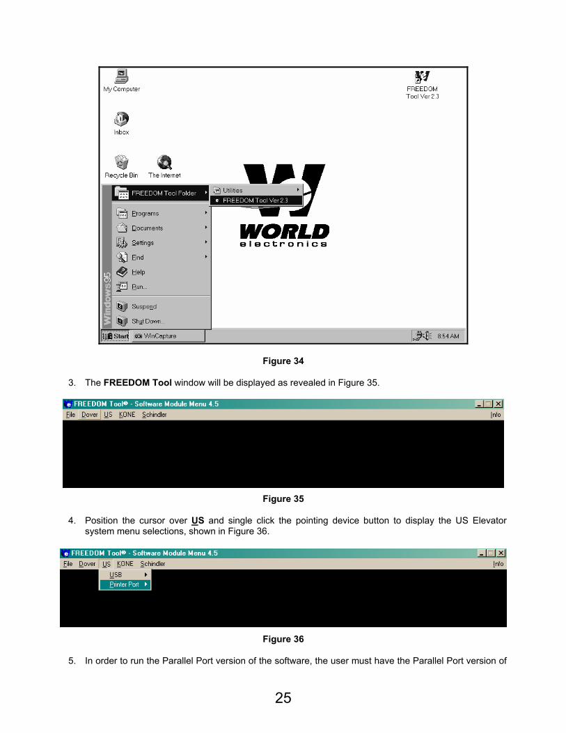
25
Figure 34
3. The FREEDOM Tool window will be displayed as revealed in Figure 35.
Figure 35
4. Position the cursor over US and single click the pointing device button to display the US Elevator system menu selections, shown in Figure 36.
Figure 36
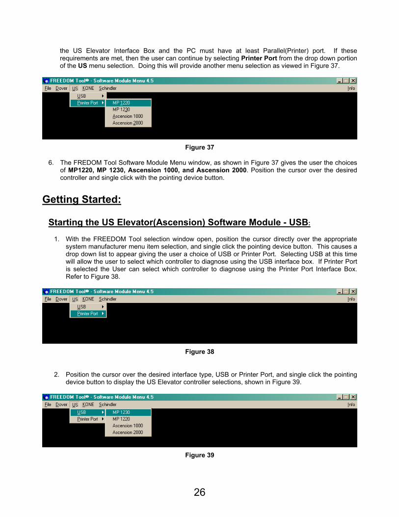
5. In order to run the Parallel Port version of the software, the user must have the Parallel Port version of
26
the US Elevator Interface Box and the PC must have at least Parallel(Printer) port. If these requirements are met, then the user can continue by selecting Printer Port from the drop down portion of the US menu selection. Doing this will provide another menu selection as viewed in Figure 37.
Figure 37
6. The FREDOM Tool Software Module Menu window, as shown in Figure 37 gives the user the choices of MP1220, MP 1230, Ascension 1000, and Ascension 2000. Position the cursor over the desired controller and single click with the pointing device button.
Getting Started:
Starting the US Elevator(Ascension) Software Module - USB:
1. With the FREEDOM Tool selection window open, position the cursor directly over the appropriate system manufacturer menu item selection, and single click the pointing device button. This causes a drop down list to appear giving the user a choice of USB or Printer Port. Selecting USB at this time will allow the user to select which controller to diagnose using the USB interface box. If Printer Port is selected the User can select which controller to diagnose using the Printer Port Interface Box. Refer to Figure 38.
Figure 38
2. Position the cursor over the desired interface type, USB or Printer Port, and single click the pointing
device button to display the US Elevator controller selections, shown in Figure 39.
Figure 39
27
3. The US Elevator service tool currently services the MP 1220, MP 1230, Ascension 1000, and the Ascension 2000 elevator control systems. To open the US Elevator(Ascension) Software module, position the cursor over any of the following choices: Ascension 2000, Ascension 1000, MP 1230, or MP 1220. When the cursor is positioned over the desired controller, single click with the pointing device button.
4. The Communication Port Set-Up window, similar to the one seen in Figure 40 will appear. Figure 40 allows the users to choose the serial port assigned to the USB Interface Box by the computer. If the USB interface box is connected to the Notebook PC and it is detected, one of the eight(8) COM pushbuttons should be in a pressed state indicating the assignment. If not, the user must select the pushbutton for the COM port assigned to the USB Interface Box. This assignment can be viewed in the Device Manager found within the control Panel of the Notebook PC. When the desired COM port is selected, the user can select the OK pushbutton. Upon clicking OK, the window will close, and the software will set up the notebook computer’s serial port for the assignment selected.
Figure 40
5. The About: Security Key Information window, as seen in Figure 41, will appear next due to the software system checking the Notebook PC for the proper security key. The security key must be plugged into the printer port of the computer or a USB port, at all times, for proper operation of the FREEDOM Tool software. It is important to note a green background surrounding the picture of the security key indicates that the security key check passed. The Security Key Information window shows the user information on the software module being used, the serial number, the expiration date, the security key check status, and connection instructions. The program can continue at this point, by positioning the cursor over one of the US Elevator Controller pushbuttons and single clicking with the pointing device button.
28
Figure 41
In the event, the security key has not been installed or a problem exists with the installed key, a About: Security Key Information window would be displayed revealing an Authorization Error Number and a Red Background surrounding a picture of a security key as in Figure 42. Take note of this error number and call WORLD electronics for help, the phone number is located below the WORLD electronics logo found on this window. To continue, position the cursor over the Close pushbutton and single click with the pointing device button. This causes the FREEDOM Tool software to terminate execution and return to the Windows desktop.
29
Figure 42
General Description:
The FREEDOM Tool is a multi-functional diagnostic tool that allows the user to do everything from diagnosing faults to setting up the elevator system. All software functions can be accessed from the FREEDOM Tool’s Main window as seen in Figure 43. On the top line of the FREEDOM Tool software module is a description of the software running. The elevator system being diagnosed will be found in this description along with the version number.
30
Figure 43
The user can maneuver throughout the FREEDOM Tool using menu choices. Along with the menu choices, the main window also contains LED Banks with description selection buttons, Status Displays, call buttons, and forward and back pushbuttons. Not all options/items are available from one control system to the next. If an option is used within the selected elevator control system, the menu item for that option will be shown in black lettering. Grey lettering is used whenever an option is disabled for a particular system.
The Menu
The FREEDOM Tool Menu consists of four(4) choices. These choices presented to the user are File, Displays, Fault Logs, and About. These 4 menu selections are described in further detail in the following:
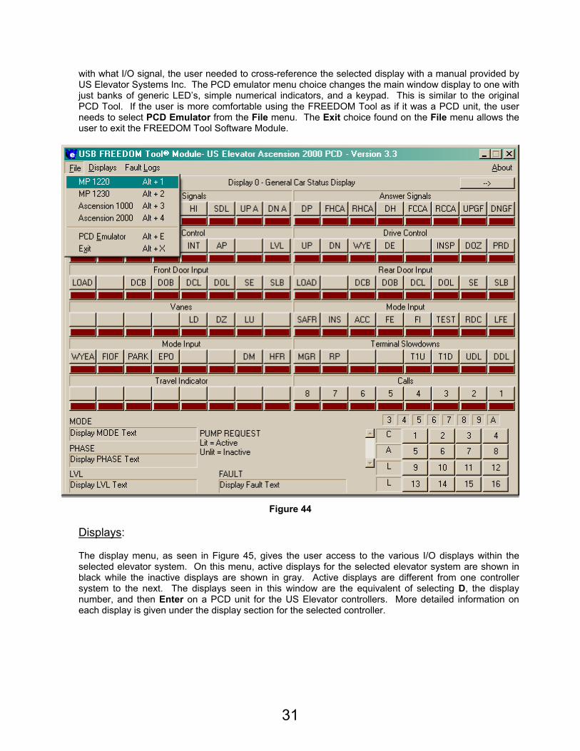
File:
Selecting the File menu, refer to Figure 44, the user is presented with choices which allow the user to set up the displays to work with the four(4) elevator controllers that the FREEDOM Tool works on. Also located on the file menu is a choice labeled Exit and one labeled PCD Emulator. Selecting an Elevator Controller from this menu will adjust the I/O display labels and menus so that they are specific to the elevator system selected. The title bar of the Main Window will always indicate what controller mode the FREEDOM Tool is in. The original PCD manufactured by US Elevator was a black box with banks of LED’s and several LCD Displays along with a numerical Keyboard. In order to determine what LED went
31
with what I/O signal, the user needed to cross-reference the selected display with a manual provided by US Elevator Systems Inc. The PCD emulator menu choice changes the main window display to one with just banks of generic LED’s, simple numerical indicators, and a keypad. This is similar to the original PCD Tool. If the user is more comfortable using the FREEDOM Tool as if it was a PCD unit, the user needs to select PCD Emulator from the File menu. The Exit choice found on the File menu allows the user to exit the FREEDOM Tool Software Module.
Figure 44
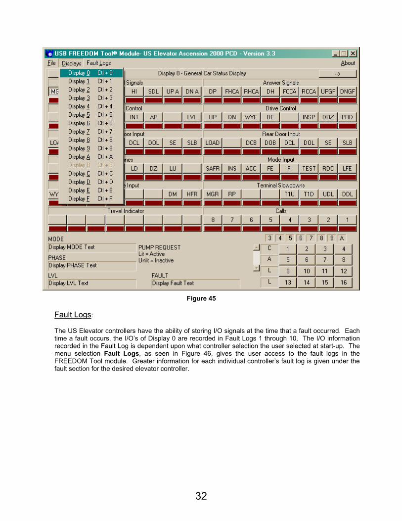
Displays:
The display menu, as seen in Figure 45, gives the user access to the various I/O displays within the selected elevator system. On this menu, active displays for the selected elevator system are shown in black while the inactive displays are shown in gray. Active displays are different from one controller system to the next. The displays seen in this window are the equivalent of selecting D, the display number, and then Enter on a PCD unit for the US Elevator controllers. More detailed information on each display is given under the display section for the selected controller.
32
Figure 45
Fault Logs:
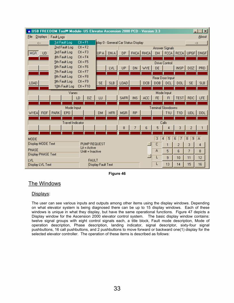
The US Elevator controllers have the ability of storing I/O signals at the time that a fault occurred. Each time a fault occurs, the I/O’s of Display 0 are recorded in Fault Logs 1 through 10. The I/O information recorded in the Fault Log is dependent upon what controller selection the user selected at start-up. The menu selection Fault Logs, as seen in Figure 46, gives the user access to the fault logs in the FREEDOM Tool module. Greater information for each individual controller’s fault log is given under the fault section for the desired elevator controller.
33
Figure 46
The Windows
Displays:
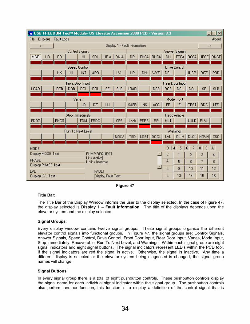
The user can see various inputs and outputs among other items using the display windows. Depending on what elevator system is being diagnosed there can be up to 15 display windows. Each of these windows is unique in what they display, but have the same operational functions. Figure 47 depicts a Display window for the Ascension 2000 elevator control system. The basic display window contains: twelve signal groups with eight control signals each, a title block, Fault mode description, Mode of operation description, Phase description, landing indicator, signal descriptor, sixty-four signal pushbuttons, 16 call pushbuttons, and 2 pushbuttons to move forward or backward one(1) display for the selected elevator controller. The operation of these items is described as follows:
34
Figure 47
Title Bar:
The Title Bar of the Display Window informs the user to the display selected. In the case of Figure 47, the display selected is Display 1 – Fault Information. The title of the displays depends upon the elevator system and the display selected.
Signal Groups:
Every display window contains twelve signal groups. These signal groups organize the different elevator control signals into functional groups. In Figure 47, the signal groups are: Control Signals, Answer Signals, Speed Control, Drive Control, Front Door Input, Rear Door Input, Vanes, Mode Input, Stop Immediately, Recoverable, Run To Next Level, and Warnings. Within each signal group are eight signal indicators and eight signal buttons. The signal indicators represent LED’s within the PCD tool. If the signal indicators are red the signal is active. Otherwise, the signal is inactive. Any time a different display is selected or the elevator system being diagnosed is changed, the signal group names will change.
Signal Buttons:
In every signal group there is a total of eight pushbutton controls. These pushbutton controls display the signal name for each individual signal indicator within the signal group. The pushbutton controls also perform another function, this function is to display a definition of the control signal that is
35
selected. To select a control signal for definition the user would maneuver the pointing device arrow over the desired control signal pushbutton and click the pointing device selector button once. When a control signal pushbutton is selected, the Signal Descriptor area, found in the bottom, center section of the display window, will update showing the signal name and the definition for the selected signal.
Signal Descriptor:
In the bottom, center portion of the display windows is a blank region. This blank region is called the Signal Descriptor. The Signal Descriptor shows the definition of the Signal Button selected along with the associated signal name.
FAULT:
The Fault indicator of the Display Window informs the user as to the fault status of the elevator controller the tool is in communication with. Each individual controller section in this manual will list the possible fault modes that the selected controller could have.
MODE:
The mode of operation of the selected controller can be determined through the Mode section of the Display Window. The Mode section informs the user as to which mode of operation the elevator controller is in. The modes are set up in order of priority. Each individual controller section of the manual lists the different modes each elevator controller could possibly have.
PHASE:
To determine what the elevator controller is trying to do, while the tool is connected it, the Phase indicator found within the Display window is used. The Phase indicator gives the user information as to what the car is doing in relationship with its motion. Each type of elevator controller has a different list of Phases it could possibly have. The specific Phase an elevator controller will have is defined under the Phase section of each individual elevator controller section.
Level:
The level indicator gives the user an indication of where the car is within the hoistway.
Call Pushbuttons:
The Call Pushbuttons found in the lower right-hand corner of the Display Window is indicated by the letters C-A-L-L on the left side of the Call Buttons. When these buttons appear in the display window, they can be used to enter a call into the Elevator Control System. They perform the equivalent task of pressing C, followed by the landing number, and then Enter. If these pushbuttons are not located on the selected display window, then calls can’t be entered through the selected window.
Personality Pushbuttons: Ascension 2000 Display 9 and A ONLY
When the Personality Windows are opened in the module geared for the Ascension 2000 elevator system, the pushbuttons found in the lower right corner will aid the user in navigating through and changing the programmable personality data. These pushbuttons are indicated by CLR (0), SET (1), GRP (E), and BIT (F). The CLR (0) pushbutton will change a personality bits state from active to inactive. SET (1) changes the personality bit’s state from inactive to active. Using the GRP (E) pushbutton places the personality display into an update state and then changes the focus from one group to the next. The BIT (F) pushbutton toggles the flashing focus through the individual bits within a group. To change a specific bit the user would use a combination of the E and F pushbuttons to navigate to the desired bit and then press either 1 or 0 to set or clear the desired personality bit.
36
CLEAR pushbutton:
Several of the display windows can be cleared using the PCD Tool. This can be done by pressing the pushbutton labeled CLEAR. This CLEAR pushbutton will appear above the Signal Descriptor area in the bottom center of the display window. Only windows that allow the FREEDOM Tool to clear their values will show the CLEAR pushbutton allowing the user to select this function. The CLEAR pushbutton is the equivalent of pressing CODE(10), C, and then Enter on the PCD Tool.
Forward and Backward Pushbuttons:
Located on either side of the Title Bar of the display window are pushbuttons that have arrow indicators on them. One arrow is pointing to the right and the other to the left. Pressing the button that points right will change the display window to the next Display Window for the selected elevator system. If you were on Display 1, pressing the Right( ) pushbutton would advance the tool display to Display 2. Conversely the Left( ) pushbutton would take the user to the previous display. While in Display 1, pressing the Left pushbutton would cause the display to change to Display 0.
Fault Log:
The Fault Log shows the basic I/O signals that were present at the time the elevator system detected a fault. The elevator system can store this log for up to ten different fault occurrences. Once ten faults have been reached, the oldest fault will be purged and replaced with the next oldest. The first fault log always shows the I/O signals (Display 0) for the most recent fault occurrence. The Fault Log window is identical in appearance and functionality of the Display window for Display 0. There is one exception, the fault log has the ability to be cleared by using the Clear pushbutton. As mentioned the Fault Log window is similar in setup to the Display Window. It contains twelve display groups with eight signal buttons, an indicator for Phase, Mode, Level, and Fault, a Signal Descriptor, a Title Bar, and a Close pushbutton. Refer to Figure 48.
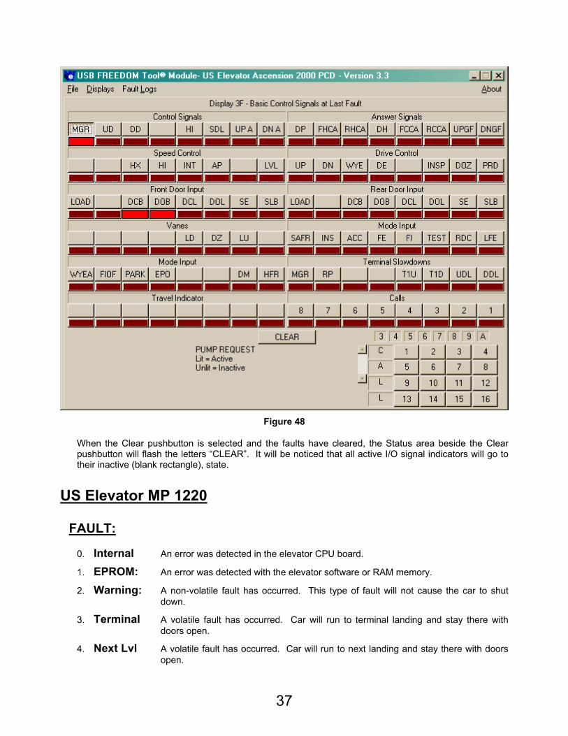
37
Figure 48
When the Clear pushbutton is selected and the faults have cleared, the Status area beside the Clear pushbutton will flash the letters “CLEAR”. It will be noticed that all active I/O signal indicators will go to their inactive (blank rectangle), state.
US Elevator MP 1220
FAULT:
0. Internal An error was detected in the elevator CPU board.
1. EPROM: An error was detected with the elevator software or RAM memory.
2. Warning: A non-volatile fault has occurred. This type of fault will not cause the car to shut down.
3. Terminal A volatile fault has occurred. Car will run to terminal landing and stay there with doors open.
4. Next Lvl A volatile fault has occurred. Car will run to next landing and stay there with doors open.
38
5. Stop Now A volatile fault has occurred. Car will stop at its immediate position in the hoistway.
PHASE: – The following is a list of phases of the run the MP 1220 controller may have.
0. Fault A fault was detected while car was running.
1. Shutdown Car has shutdown.
2. Lost Car has lost its position within the hoistway.
3. Wakeup Car is just starting.
4. Rest Car is parked at landing.
5. Relevel Car is releveling into a landing.
6. Level Car is running at leveling speed.
8. Approach Car is decelerating into a landing.
9. Intermediate Car is accelerating from landing.
A. High Car is running at high speed.
MODE: The following is a list of modes of operation that the MP 1220 controller may have. They are listed in order of priority, with the top mode having highest priority.
0. Restart Car CPU communication lock (Should not be seen through service tool)
1. Inspect Inspection operation.
2. Access Hoistway Access.
3. Fire Ind. Fireman’s Service Phase 2.
4. Fault System contains a fault. Fault display – Stop Now has occurred.
5. Test CPS I/O board toggle switch in test position (down).
6. Emerg. Power Car is on emergency power operation. Generator is providing main car power.
7. Fire Return Fireman’s Service Phase 1
8. Test Rqst. CPS I/O board toggle switch in test position but car calls are in the system. When car calls are answered, mode will change to Test.
9. Secure Park Car will park at secure landing with doors either open or closed, depending on personality setup.
A. Independent Car is on independent service operation.
B. Sp. Srv. I Hall Station special service operation activated. All car calls are answered before car responds to special service floor.
C. Sp. Srv. II Hall Station special service operation activated. All car calls are canceled before car responds to designated special service floor.
D. Automatic Car is on automatic service.
39
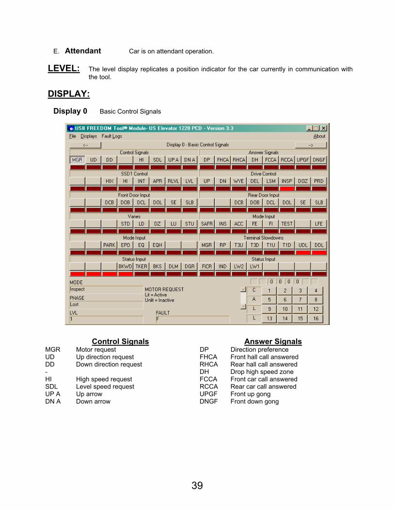
E. Attendant Car is on attendant operation.
LEVEL: The level display replicates a position indicator for the car currently in communication with the tool.
DISPLAY:
Display 0 Basic Control Signals
Control Signals Answer Signals MGR Motor request DP Direction preference UD Up direction request FHCA Front hall call answered DD Down direction request RHCA Rear hall call answered - DH Drop high speed zone HI High speed request FCCA Front car call answered SDL Level speed request RCCA Rear car call answered UP A Up arrow UPGF Front up gong DN A Down arrow DNGF Front down gong
40
SSD1 Control Drive Control
- UP Up direction - DN Down direction HIX High speed indicator WYE WYE signal HI High speed command DEL Delta signal INT Intermediate speed command LSM Low speed monitor APR Approach speed command INSP Inspection RLVL Relevel speed command DOZ Door open zone LVL Level speed command PRD Power drive
Front Door Input Rear Door Input
- - - - DCB Front door close button DCB Rear door close button DOB Front door open button DOB Rear door open button DCL Front door close limit DCL Rear door close limit DOL Front door open limit DOL Rear door open limit SE Front safety edge SE Rear safety edge SLB Front safety ray SLB Rear safety ray
Vanes Mode Input
- SAFR Car safety string - INS Inspection - ACC Access STD Down stepping vane FE Fireman’s emergency return – Phase 1 LD Level down vane FI Fireman’s independent – Phase 2 DZ Door zone vane TEST Test LU Level up vane - STU Up stepping vane LFE Lobby fire – Alternate fire service
Mode Input Terminal Slowdowns
- MGR Motor request - RP 3 phase status PARK Secure park T3U Up terminal slowdown switch #3 EPO Emergency power T3D Down terminal slowdown switch #3 EQ Earthquake detection circuit T1U Up slowdown switch
EQH Earthquake hold – Counterweight collision T1D Down slowdown switch
UDL Up directional limit DDL Down directional limit
Status Input Status Input
- FICR Phase 2 Fireman’s Service - Call Reset - IND Independent Service - LW 2 Loadweigher switch 2 BKWD Brake watchdog circuit LW 1 Loadweigher switch 1 TKER Tachometer error - BKS Brake switch - DLM Door lock contacts - DGR Door gate relay -
41
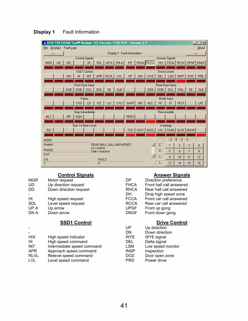
Display 1 Fault Information
Control Signals Answer Signals MGR Motor request DP Direction preference UD Up direction request FHCA Front hall call answered DD Down direction request RHCA Rear hall call answered - DH Drop high speed zone HI High speed request FCCA Front car call answered SDL Level speed request RCCA Rear car call answered UP A Up arrow UPGF Front up gong DN A Down arrow DNGF Front down gong
SSD1 Control Drive Control
- UP Up direction - DN Down direction HIX High speed indicator WYE WYE signal HI High speed command DEL Delta signal INT Intermediate speed command LSM Low speed monitor APR Approach speed command INSP Inspection RLVL Relevel speed command DOZ Door open zone LVL Level speed command PRD Power drive
42
Front Door Input Rear Door Input
- - - - DCB Front door close button DCB Rear door close button DOB Front door open button DOB Rear door open button DCL Front door close limit DCL Rear door close limit DOL Front door open limit DOL Rear door open limit SE Front safety edge SE Rear safety edge SLB Front safety ray SLB Rear safety ray
Vanes Mode Input
- SAFR Car safety string - INS Inspection - ACC Access STD Down stepping vane FE Fireman’s emergency return – Phase 1 LD Level down vane FI Fireman’s independent – Phase 2 DZ Door zone vane TEST Test LU Level up vane - STU Up stepping vane LFE Lobby fire – Alternate fire service
Stop Immediately Recoverable
MLT Motor Limit Timer PERS Personality Fault - - PARK Reverse Phase Check -
EPO Earthquake hold – Counterweight collision -
EQ - EQH - - -
Run to Next Level Warnings
EQ Earthquake detection circuit TSD Top and Bottom Slowdown Active - LOST Car Lost
- DOCL Door Close Limit and Door Close Limit Active
- LVL Level Up and Level Down Active - DLIM Direction Limit - DLCK Door Lock - NOVN No Vane - -
43
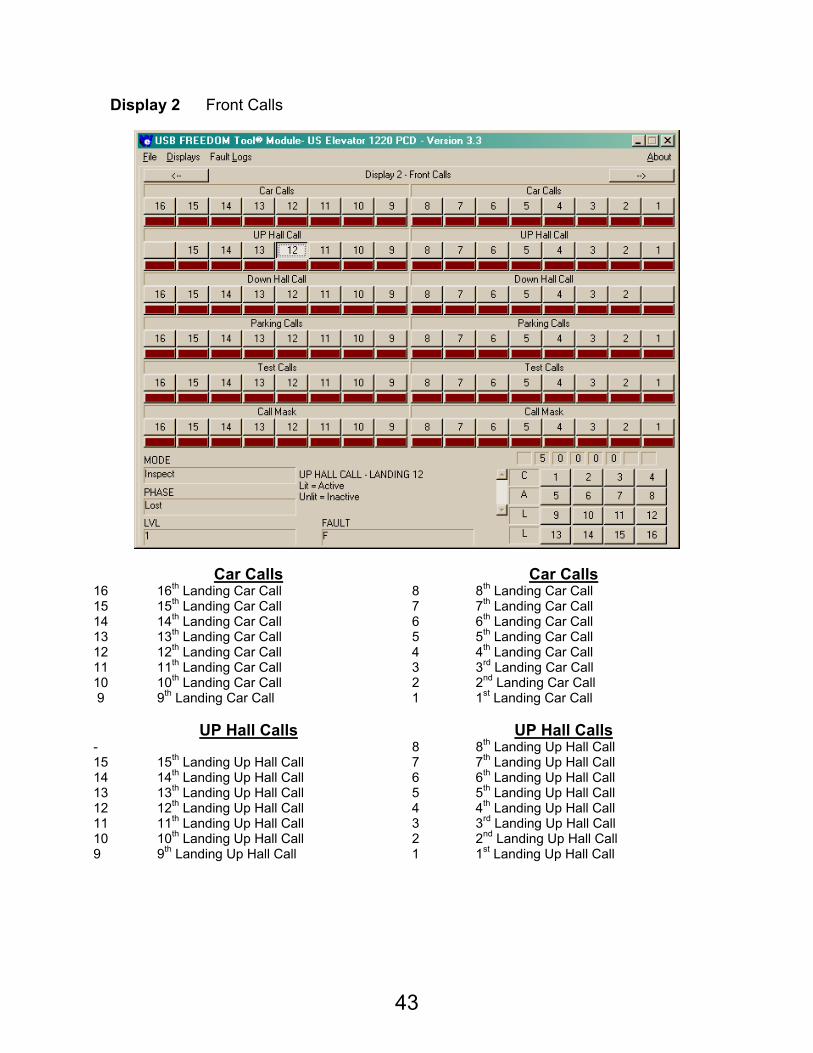
Display 2 Front Calls
Car Calls Car Calls 16 16th Landing Car Call 8 8th Landing Car Call 15 15th Landing Car Call 7 7th Landing Car Call 14 14th Landing Car Call 6 6th Landing Car Call 13 13th Landing Car Call 5 5th Landing Car Call 12 12th Landing Car Call 4 4th Landing Car Call 11 11th Landing Car Call 3 3rd Landing Car Call 10 10th Landing Car Call 2 2nd Landing Car Call 9 9th Landing Car Call 1 1st Landing Car Call
UP Hall Calls UP Hall Calls
- 8 8th Landing Up Hall Call 15 15th Landing Up Hall Call 7 7th Landing Up Hall Call 14 14th Landing Up Hall Call 6 6th Landing Up Hall Call 13 13th Landing Up Hall Call 5 5th Landing Up Hall Call 12 12th Landing Up Hall Call 4 4th Landing Up Hall Call 11 11th Landing Up Hall Call 3 3rd Landing Up Hall Call 10 10th Landing Up Hall Call 2 2nd Landing Up Hall Call 9 9th Landing Up Hall Call 1 1st Landing Up Hall Call

44
Down Hall Calls Down Hall Calls
16 16th Landing Down Hall Call 8 8th Landing Down Hall Call 15 15th Landing Down Hall Call 7 7th Landing Down Hall Call 14 14th Landing Down Hall Call 6 6th Landing Down Hall Call 13 13th Landing Down Hall Call 5 5th Landing Down Hall Call 12 12th Landing Down Hall Call 4 4th Landing Down Hall Call 11 11th Landing Down Hall Call 3 3rd Landing Down Hall Call 10 10th Landing Down Hall Call 2 2nd Landing Down Hall Call 9 9th Landing Down Hall Call -
Parking Calls Parking Calls
16 Car requested to park at 16th landing 8 Car requested to park at 8th landing 15 Car requested to park at 15th landing 7 Car requested to park at 7th landing 14 Car requested to park at 14th landing 6 Car requested to park at 6th landing 13 Car requested to park at 13th landing 5 Car requested to park at 5th landing 12 Car requested to park at 12th landing 4 Car requested to park at 4th landing 11 Car requested to park at 11th landing 3 Car requested to park at 3rd landing 10 Car requested to park at 10th landing 2 Car requested to park at 2nd landing 9 Car requested to park at 9th landing 1 Car requested to park at 1st landing
Test Calls Test Calls
16 Test call placed at 16th landing 8 Test call placed at 8th landing 15 Test call placed at 15th landing 7 Test call placed at 7th landing 14 Test call placed at 14th landing 6 Test call placed at 6th landing 13 Test call placed at 13th landing 5 Test call placed at 5th landing 12 Test call placed at 12th landing 4 Test call placed at 4th landing 11 Test call placed at 11th landing 3 Test call placed at 3rd landing 10 Test call placed at 10th landing 2 Test call placed at 2nd landing 9 Test call placed at 9th landing 1 Test call placed at 1st landing
Call Mask Call Mask
16 16th landing enabled 8 8th landing enabled 15 15th landing enabled 7 7th landing enabled 14 14th landing enabled 6 6th landing enabled 13 13th landing enabled 5 5th landing enabled 12 12th landing enabled 4 4th landing enabled 11 11th landing enabled 3 3rd landing enabled 10 10th landing enabled 2 2nd landing enabled 9 9th landing enabled 1 1st landing enabled
45
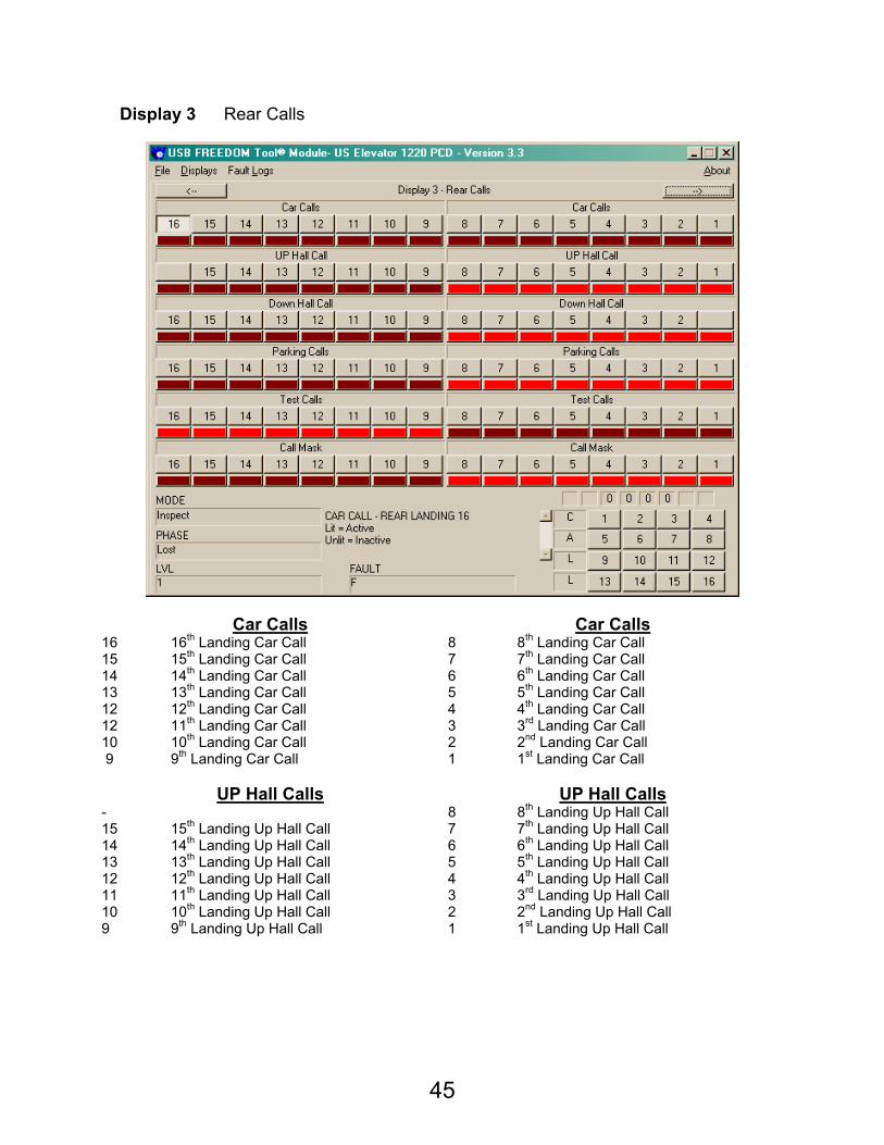
Display 3 Rear Calls
Car Calls Car Calls 16 16th Landing Car Call 8 8th Landing Car Call 15 15th Landing Car Call 7 7th Landing Car Call 14 14th Landing Car Call 6 6th Landing Car Call 13 13th Landing Car Call 5 5th Landing Car Call 12 12th Landing Car Call 4 4th Landing Car Call 12 11th Landing Car Call 3 3rd Landing Car Call 10 10th Landing Car Call 2 2nd Landing Car Call 9 9th Landing Car Call 1 1st Landing Car Call
UP Hall Calls UP Hall Calls
- 8 8th Landing Up Hall Call 15 15th Landing Up Hall Call 7 7th Landing Up Hall Call 14 14th Landing Up Hall Call 6 6th Landing Up Hall Call 13 13th Landing Up Hall Call 5 5th Landing Up Hall Call 12 12th Landing Up Hall Call 4 4th Landing Up Hall Call 11 11th Landing Up Hall Call 3 3rd Landing Up Hall Call 10 10th Landing Up Hall Call 2 2nd Landing Up Hall Call 9 9th Landing Up Hall Call 1 1st Landing Up Hall Call
46
Down Hall Calls Down Hall Calls
16 16th Landing Down Hall Call 8 8th Landing Down Hall Call 15 15th Landing Down Hall Call 7 7th Landing Down Hall Call 14 14th Landing Down Hall Call 6 6th Landing Down Hall Call 13 13th Landing Down Hall Call 5 5th Landing Down Hall Call 12 12th Landing Down Hall Call 4 4th Landing Down Hall Call 11 11th Landing Down Hall Call 3 3rd Landing Down Hall Call 10 10th Landing Down Hall Call 2 2nd Landing Down Hall Call 9 9th Landing Down Hall Call -
Parking Calls Parking Calls
16 Car requested to park at 16th landing 8 Car requested to park at 8th landing 15 Car requested to park at 15th landing 7 Car requested to park at 7th landing 14 Car requested to park at 14th landing 6 Car requested to park at 6th landing 13 Car requested to park at 13th landing 5 Car requested to park at 5th landing 12 Car requested to park at 12th landing 4 Car requested to park at 4th landing 11 Car requested to park at 11th landing 3 Car requested to park at 3rd landing 10 Car requested to park at 10th landing 2 Car requested to park at 2nd landing 9 Car requested to park at 9th landing 1 Car requested to park at 1st landing
Test Calls Test Calls
16 Test call placed at 16th landing 8 Test call placed at 8th landing 15 Test call placed at 15th landing 7 Test call placed at 7th landing 14 Test call placed at 14th landing 6 Test call placed at 6th landing 13 Test call placed at 13th landing 5 Test call placed at 5th landing 12 Test call placed at 12th landing 4 Test call placed at 4th landing 11 Test call placed at 11th landing 3 Test call placed at 3rd landing 10 Test call placed at 10th landing 2 Test call placed at 2nd landing 9 Test call placed at 9th landing 1 Test call placed at 1st landing
Call Mask Call Mask
16 16th landing enabled 8 8th landing enabled 15 15th landing enabled 7 7th landing enabled 14 14th landing enabled 6 6th landing enabled 13 13th landing enabled 5 5th landing enabled 12 12th landing enabled 4 4th landing enabled 11 11th landing enabled 3 3rd landing enabled 10 10th landing enabled 2 2nd landing enabled 9 9th landing enabled 1 1st landing enabled
47
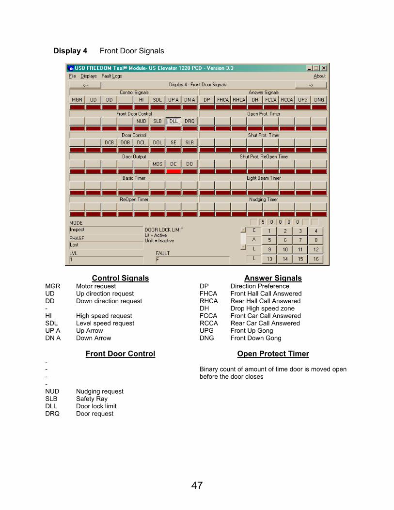
Display 4 Front Door Signals
Control Signals Answer Signals MGR Motor request DP Direction Preference UD Up direction request FHCA Front Hall Call Answered DD Down direction request RHCA Rear Hall Call Answered - DH Drop High speed zone HI High speed request FCCA Front Car Call Answered SDL Level speed request RCCA Rear Car Call Answered UP A Up Arrow UPG Front Up Gong DN A Down Arrow DNG Front Down Gong
Front Door Control Open Protect Timer
- - - -
Binary count of amount of time door is moved open before the door closes
NUD Nudging request SLB Safety Ray DLL Door lock limit DRQ Door request
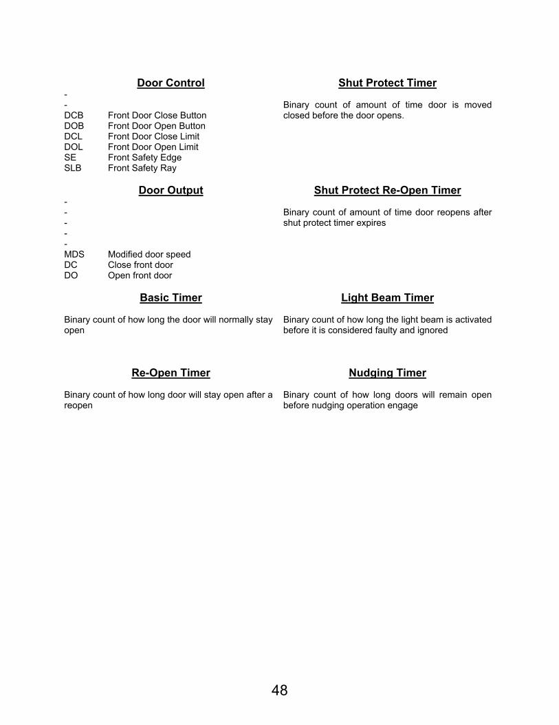
48
Door Control Shut Protect Timer
- - DCB Front Door Close Button DOB Front Door Open Button
Binary count of amount of time door is moved closed before the door opens.
DCL Front Door Close Limit DOL Front Door Open Limit SE Front Safety Edge SLB Front Safety Ray
Door Output Shut Protect Re-Open Timer
- - - -
Binary count of amount of time door reopens after shut protect timer expires
- MDS Modified door speed DC Close front door DO Open front door
Basic Timer Light Beam Timer
Binary count of how long the door will normally stay open
Binary count of how long the light beam is activated before it is considered faulty and ignored
Re-Open Timer Nudging Timer Binary count of how long door will stay open after a reopen
Binary count of how long doors will remain open before nudging operation engage
49
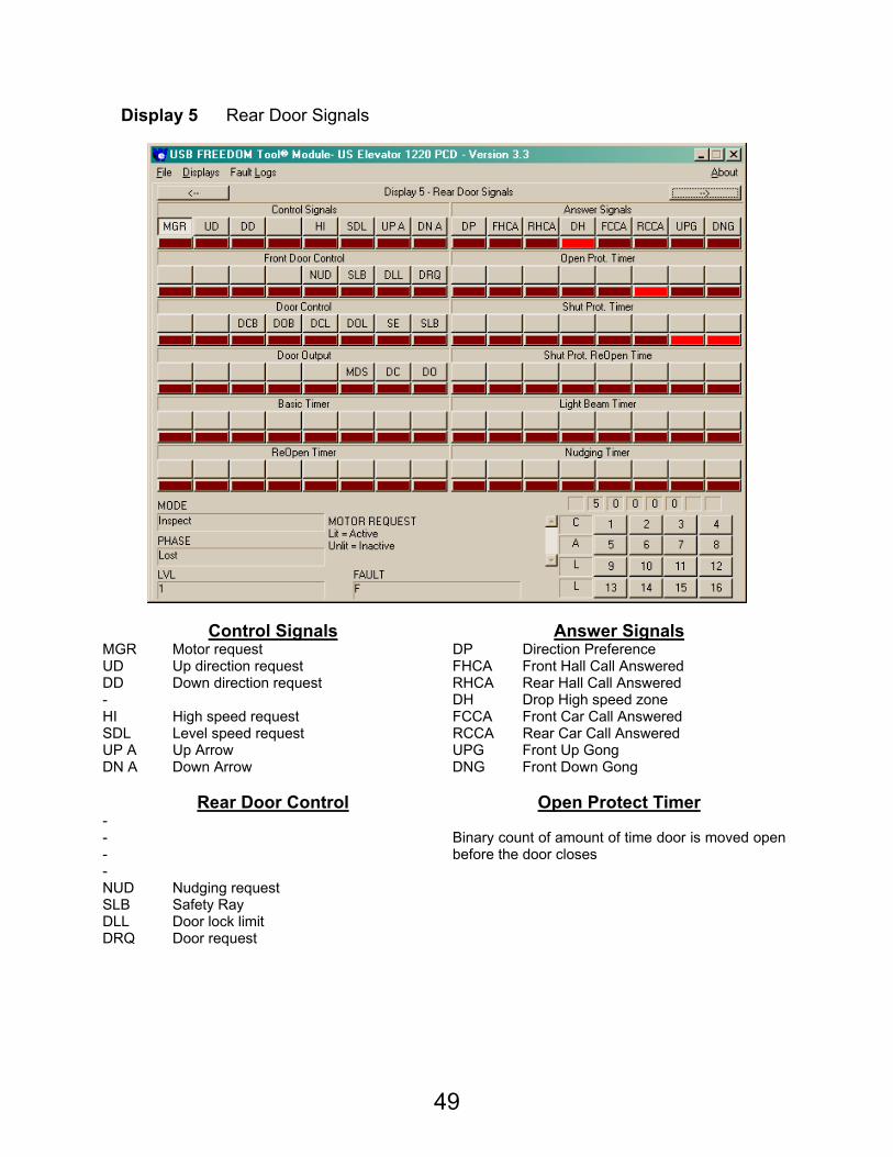
Display 5 Rear Door Signals
Control Signals Answer Signals MGR Motor request DP Direction Preference UD Up direction request FHCA Front Hall Call Answered DD Down direction request RHCA Rear Hall Call Answered - DH Drop High speed zone HI High speed request FCCA Front Car Call Answered SDL Level speed request RCCA Rear Car Call Answered UP A Up Arrow UPG Front Up Gong DN A Down Arrow DNG Front Down Gong
Rear Door Control Open Protect Timer
- - - -
Binary count of amount of time door is moved open before the door closes
NUD Nudging request SLB Safety Ray DLL Door lock limit DRQ Door request

50
Door Control Shut Protect Timer
- - DCB Front Door Close Button DOB Front Door Open Button
Binary count of amount of time door is moved closed before the door opens.
DCL Front Door Close Limit DOL Front Door Open Limit SE Front Safety Edge SLB Front Safety Ray
Door Output Shut Protect Re-Open Timer
- - - -
Binary count of amount of time door reopens after shut protect timer expires
- MDS Modified door speed DC Close front door DO Open front door
Basic Timer Light Beam Timer
Binary count of how long the door will normally stay open
Binary count of how long the light beam is activated before it is considered faulty and ignored
Re-Open Timer Nudging Timer Binary count of how long door will stay open after a reopen
Binary count of how long doors will remain open before nudging operation engage
51
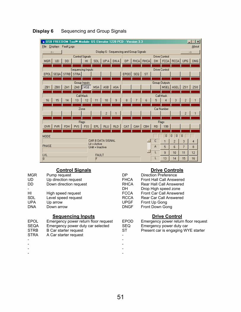
Display 6 Sequencing and Group Signals
Control Signals Drive Controls MGR Pump request DP Direction Preference UD Up direction request FHCA Front Hall Call Answered DD Down direction request RHCA Rear Hall Call Answered - DH Drop High speed zone HI High speed request FCCA Front Car Call Answered SDL Level speed request RCCA Rear Car Call Answered UPA Up arrow UPGF Front Up Gong DNA Down arrow DNGF Front Down Gong
Sequencing Inputs Drive Control
EPOL Emergency power return floor request EPOD Emergency power return floor request SEQA Emergency power duty car selected SEQ Emergency power duty car STRB B Car starter request ST Present car is engaging WYE starter STRA A Car starter request - - - - - - - - -
52
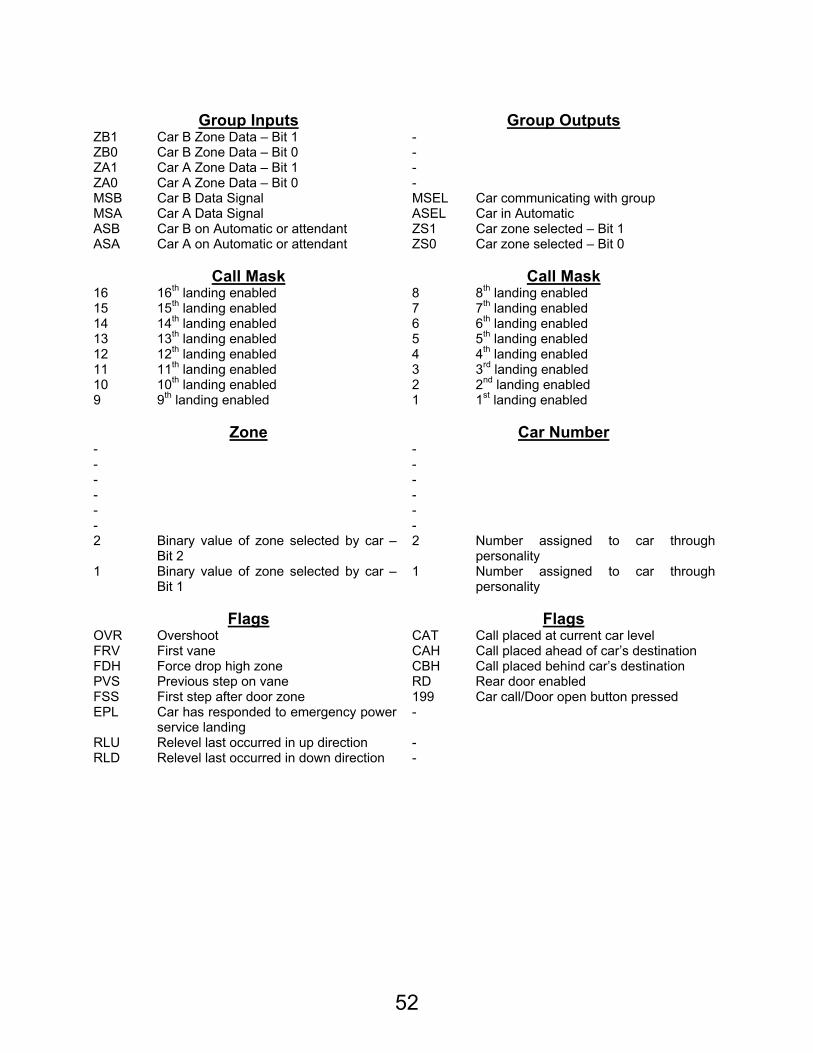
Group Inputs Group Outputs
ZB1 Car B Zone Data – Bit 1 - ZB0 Car B Zone Data – Bit 0 - ZA1 Car A Zone Data – Bit 1 - ZA0 Car A Zone Data – Bit 0 - MSB Car B Data Signal MSEL Car communicating with group MSA Car A Data Signal ASEL Car in Automatic ASB Car B on Automatic or attendant ZS1 Car zone selected – Bit 1 ASA Car A on Automatic or attendant ZS0 Car zone selected – Bit 0
Call Mask Call Mask
16 16th landing enabled 8 8th landing enabled 15 15th landing enabled 7 7th landing enabled 14 14th landing enabled 6 6th landing enabled 13 13th landing enabled 5 5th landing enabled 12 12th landing enabled 4 4th landing enabled 11 11th landing enabled 3 3rd landing enabled 10 10th landing enabled 2 2nd landing enabled 9 9th landing enabled 1 1st landing enabled
Zone Car Number
- - - - - - - - - - - - 2 Binary value of zone selected by car –
Bit 2 2 Number assigned to car through
personality 1 Binary value of zone selected by car –
Bit 1 1 Number assigned to car through
personality
Flags Flags OVR Overshoot CAT Call placed at current car level FRV First vane CAH Call placed ahead of car’s destination FDH Force drop high zone CBH Call placed behind car’s destination PVS Previous step on vane RD Rear door enabled FSS First step after door zone 199 Car call/Door open button pressed EPL Car has responded to emergency power
service landing -
RLU Relevel last occurred in up direction - RLD Relevel last occurred in down direction -
53
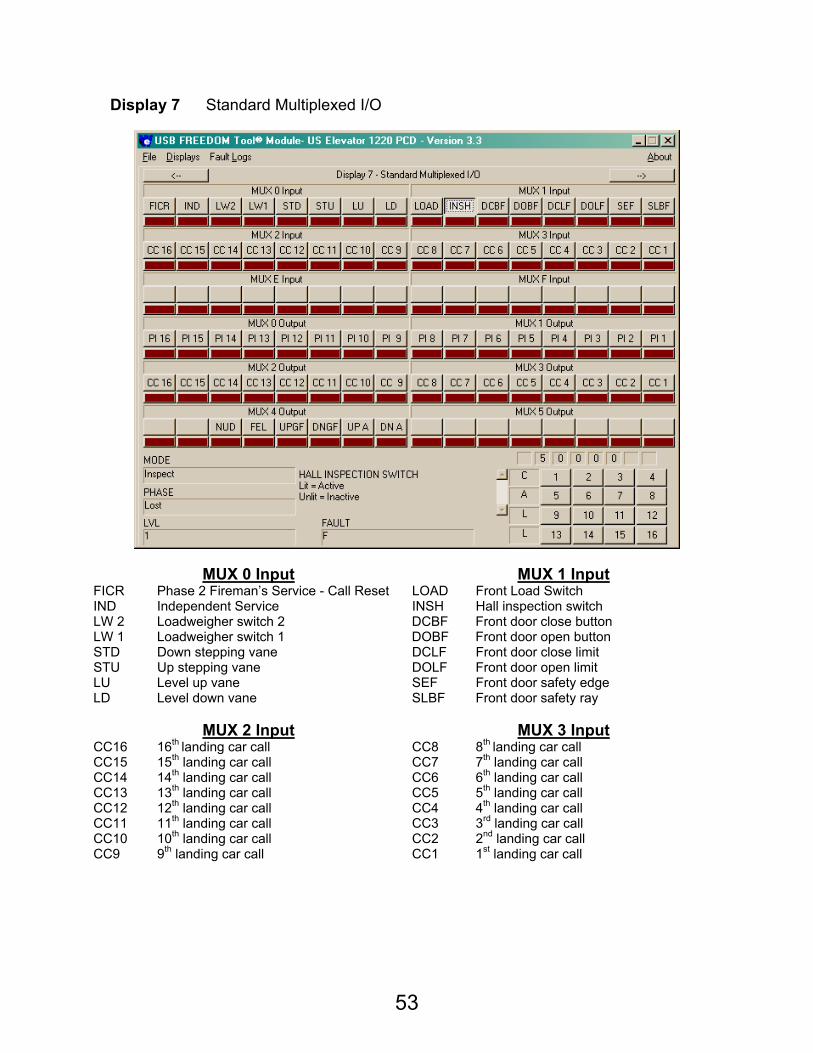
Display 7 Standard Multiplexed I/O
MUX 0 Input MUX 1 Input FICR Phase 2 Fireman’s Service - Call Reset LOAD Front Load Switch IND Independent Service INSH Hall inspection switch LW 2 Loadweigher switch 2 DCBF Front door close button LW 1 Loadweigher switch 1 DOBF Front door open button STD Down stepping vane DCLF Front door close limit STU Up stepping vane DOLF Front door open limit LU Level up vane SEF Front door safety edge LD Level down vane SLBF Front door safety ray
MUX 2 Input MUX 3 Input
CC16 16th landing car call CC8 8th landing car call CC15 15th landing car call CC7 7th landing car call CC14 14th landing car call CC6 6th landing car call CC13 13th landing car call CC5 5th landing car call CC12 12th landing car call CC4 4th landing car call CC11 11th landing car call CC3 3rd landing car call CC10 10th landing car call CC2 2nd landing car call CC9 9th landing car call CC1 1st landing car call
54
MUX E Input MUX F Input
- -
MUX 0 Output MUX 1 Output PI16 16th landing position indicator PI8 8th landing position indicator PI15 15th landing position indicator PI7 7th landing position indicator PI14 14th landing position indicator PI6 6th landing position indicator PI13 13th landing position indicator PI5 5th landing position indicator PI12 12th landing position indicator PI4 4th landing position indicator PI11 11th landing position indicator PI3 3rd landing position indicator PI10 10th landing position indicator PI2 2nd landing position indicator PI9 9th landing position indicator PI1 1st landing position indicator
MUX 2 Output MUX 3 Output
CC16 16th landing car call CC8 8th landing car call CC15 15th landing car call CC7 7th landing car call CC14 14th landing car call CC6 6th landing car call CC13 13th landing car call CC5 5th landing car call CC12 12th landing car call CC4 4th landing car call CC11 11th landing car call CC3 3rd landing car call CC10 10th landing car call CC2 2nd landing car call CC9 9th landing car call CC1 1st landing car call
MUX 4 Output MUX 5 Output
- - - - NUD Nudging buzzer - FEL Fire emergency light - UPGF Front Up Gong - DNGF Front Down Gong - UP A Up Arrow - DN A Down Arrow -
55
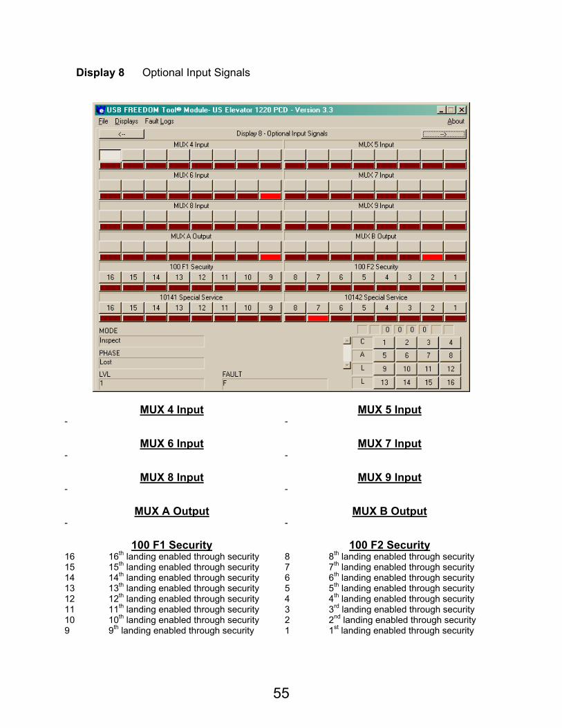
Display 8 Optional Input Signals
MUX 4 Input MUX 5 Input - -
MUX 6 Input MUX 7 Input
- -
MUX 8 Input MUX 9 Input - -
MUX A Output MUX B Output
- -
100 F1 Security 100 F2 Security 16 16th landing enabled through security 8 8th landing enabled through security 15 15th landing enabled through security 7 7th landing enabled through security 14 14th landing enabled through security 6 6th landing enabled through security 13 13th landing enabled through security 5 5th landing enabled through security 12 12th landing enabled through security 4 4th landing enabled through security 11 11th landing enabled through security 3 3rd landing enabled through security 10 10th landing enabled through security 2 2nd landing enabled through security 9 9th landing enabled through security 1 1st landing enabled through security
56
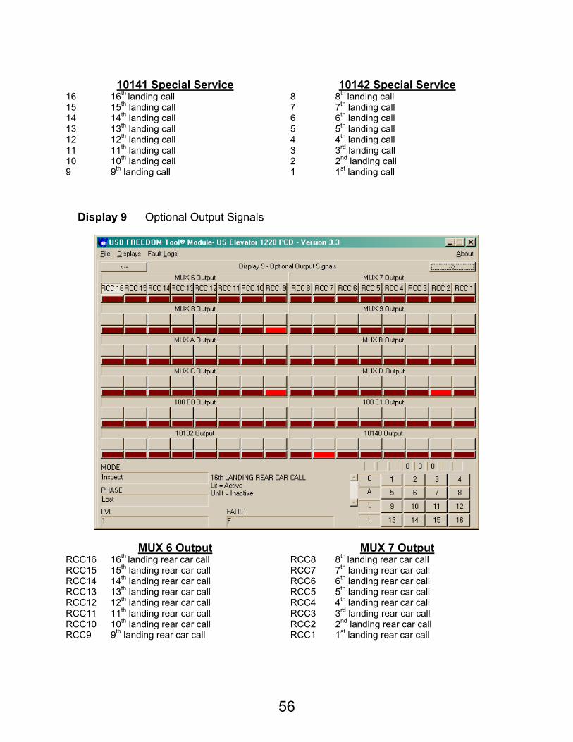
10141 Special Service 10142 Special Service
16 16th landing call 8 8th landing call 15 15th landing call 7 7th landing call 14 14th landing call 6 6th landing call 13 13th landing call 5 5th landing call 12 12th landing call 4 4th landing call 11 11th landing call 3 3rd landing call 10 10th landing call 2 2nd landing call 9 9th landing call 1 1st landing call
Display 9 Optional Output Signals
MUX 6 Output MUX 7 Output RCC16 16th landing rear car call RCC8 8th landing rear car call RCC15 15th landing rear car call RCC7 7th landing rear car call RCC14 14th landing rear car call RCC6 6th landing rear car call RCC13 13th landing rear car call RCC5 5th landing rear car call RCC12 12th landing rear car call RCC4 4th landing rear car call RCC11 11th landing rear car call RCC3 3rd landing rear car call RCC10 10th landing rear car call RCC2 2nd landing rear car call RCC9 9th landing rear car call RCC1 1st landing rear car call
57
MUX 8 Output MUX 9 Output
- -
MUX A Output MUX B Output - -
MUX C Output MUX D Ouput
- -
100 E0 Output 100 E1 Output - -
10132 Output 10140 Output
-
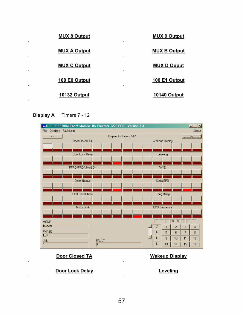
Display A Timers 7 - 12
Door Closed TA Wakeup Display - -
Door Lock Delay Leveling
- -
58
PPRD / PRDA Hold On WYE
- -
Delta Normal Delta EPO - -
CPU Reset Timer Gong Delay
-
Motor Limit EPO Sequence -
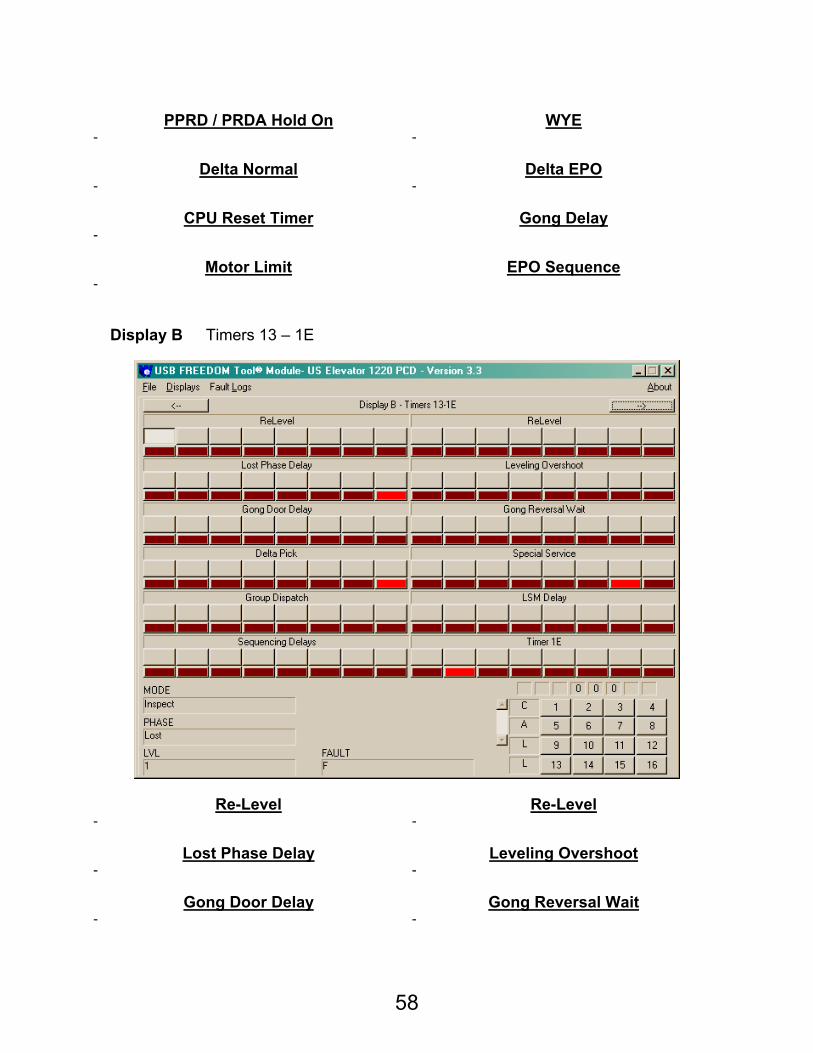
Display B Timers 13 – 1E
Re-Level Re-Level - -
Lost Phase Delay Leveling Overshoot
- -
Gong Door Delay Gong Reversal Wait - -
59
Delta Pick Special Service - -
Group Dispatch LSM Delay
-
Sequencing Delays Timer 1E -
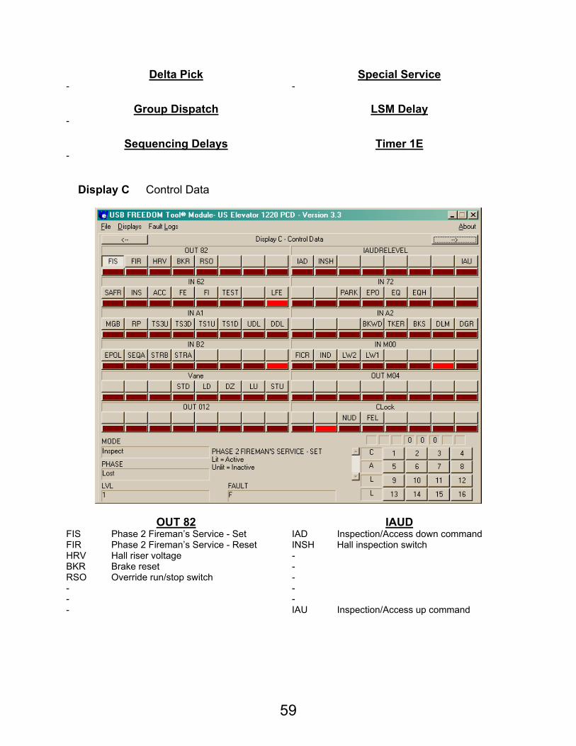
Display C Control Data
OUT 82 IAUD FIS Phase 2 Fireman’s Service - Set IAD Inspection/Access down command FIR Phase 2 Fireman’s Service - Reset INSH Hall inspection switch HRV Hall riser voltage - BKR Brake reset - RSO Override run/stop switch - - - - - - IAU Inspection/Access up command
60
IN 62 IN 72
SAFR Car Safety String - INS Inspection - ACC Access PARK Secure Park FE Fireman’s Emergency Return – Phase 1 EPO Emergency Power FI Fireman’s Independent – Phase 2 EQ Earthquake detection circuit
TEST Test mode EQH Earthquake hold – Counterweight collision
- - LFE Lobby Fire – Alternate Fire Service -
IN A1 IN A2
MGR Motor Request - RP 3 Phase Status - TS3U Up Terminal Slowdown Switch #3 PARK Secure Park TS3D Down Terminal Slowdown Switch #3 EPO Emergency Power TS1U Up Slowdown Switch EQ Earthquake detection circuit
TS1D Down Slowdown Switch EQH Earthquake hold – Counterweight collision
UDL Up Directional Limit - DDL Down Directional Limit -
IN B2 IN M00
EPOL Emergency power return floor request FICR Phase 2 Fireman’s Service - Call Reset SEQA Emergency power duty car selected IND Independent Service STRB B Car starter request LW 2 Loadweigher switch 2 STRA A Car starter request LW 1 Loadweigher switch 1 - - - - - - - -
Vane OUT M04
- - - - - - STD Down stepping vane - LD Level down vane - DZ Door zone sensor - LU Level up vane - STU Up stepping vane -
OUT 012 Clock
- - - - - NUD Nudging buzzer - FEL Fire emergency light - - - - - - - -
61
Display D Option Input
OPT 1 OPT 2 - OAL Open door at lobby
- FCLS Fireman’s service – Phase II – disable short door time
- FISE Fireman’s service – Phase II – disable safety edge
- FDOB Front/rear door open pushbutton AUDP Audible passing tone FRSE Front/rear door safety edge SCLB Secure lobby stop FRILK Front/rear door interlock SHC Secure hall call RDR Rear door in operation
SECU Security operation used INDOV Fireman’s service is overridden by Independent service
OPT 3 OPT 8
SDC - CCG - CCON - SS2 - SS1 - TEST Enable call test cycle NNDG Nudging disabled in lobby PARK Park with door open enabled. NDG Nudging operation - TIMR Nudging timer
62
OPT 9 DRLBYT
- -
OR TIME MAXCAR - -
CARNO Car PI Type
- -
Hall PI Type PARKFG - -
Display E Option Input
Lobby Level Lobby Level 16 Lobby at 16th landing 8 Lobby at 8th landing 15 Lobby at 15th landing 7 Lobby at 7th landing 14 Lobby at 14th landing 6 Lobby at 6th landing 13 Lobby at 13th landing 5 Lobby at 5th landing 12 Lobby at 12th landing 4 Lobby at 4th landing 11 Lobby at 11th landing 3 Lobby at 3rd landing 10 Lobby at 10th landing 2 Lobby at 2nd landing 9 Lobby at 9th landing 1 Lobby at 1st landing
63
Park Level Park Level
16 Car parks at 16th landing 8 Car parks at 8th landing 15 Car parks at 15th landing 7 Car parks at 7th landing 14 Car parks at 14th landing 6 Car parks at 6th landing 13 Car parks at 13th landing 5 Car parks at 5th landing 12 Car parks at 12th landing 4 Car parks at 4th landing 11 Car parks at 11th landing 3 Car parks at 3rd landing 10 Car parks at 10th landing 2 Car parks at 2nd landing 9 Car parks at 9th landing 1 Car parks at 1st landing
EMS Level EMS Level
16 EMS at 16th landing 8 EMS at 8th landing 15 EMS at 15th landing 7 EMS at 7th landing 14 EMS at 14th landing 6 EMS at 6th landing 13 EMS at 13th landing 5 EMS at 5th landing 12 EMS at 12th landing 4 EMS at 4th landing 11 EMS at 11th landing 3 EMS at 3rd landing 10 EMS at 10th landing 2 EMS at 2nd landing 9 EMS at 9th landing 1 EMS at 1st landing
Top Level Top Level
16 Top landing is 16th floor 8 Top landing is 8th floor 15 Top landing is 15th floor 7 Top landing is 7th floor 14 Top landing is 14th floor 6 Top landing is 6th floor 13 Top landing is 13th floor 5 Top landing is 5th floor 12 Top landing is 12th floor 4 Top landing is 4th floor 11 Top landing is 11th floor 3 Top landing is 3rd floor 10 Top landing is 10th floor 2 Top landing is 2nd floor 9 Top landing is 9th floor 1 Top landing is 1st floor
RS Level RS Level
16 RS at 16th landing 8 RS at 8th landing 15 RS at 15th landing 7 RS at 7th landing 14 RS at 14th landing 6 RS at 6th landing 13 RS at 13th landing 5 RS at 5th landing 12 RS at 12th landing 4 RS at 4th landing 11 RS at 11th landing 3 RS at 3rd landing 10 RS at 10th landing 2 RS at 2nd landing 9 RS at 9th landing 1 RS at 1st landing
US Elevator MP 1230
FAULT:
0. EPROM An error was detected with the elevator software or RAM memory.
1. EPROM An error was detected with the elevator software or RAM memory.
2. EPROM An error was detected with the elevator software or RAM memory.
3. EPROM An error was detected with the elevator software or RAM memory.
64
4. Warning A non-volatile fault has occurred. This type of fault will not cause the car to shut down.
5. Motor Limit Motor limit timer has expired. Car will run to terminal landing and stay there with doors open.
6. Personality An error is detected with personality settings. Car will stop where it is.
7. Run Fail Car has failed to start six times in twenty seconds. Car will run to bottom landing and sit with doors open.
8. Reverse Phase Reverse phase relay has dropped. Car will run to bottom landing and sit with doors open.
PHASE: The following is a list of phases of the run the MP 1230 controller may have.
0. Fault A fault was detected while car was running.
1. Shutdown Car has shutdown.
2. Lost Car has lost its position within the hoistway.
3. Wakeup Car is just starting.
4. Rest Car is parked at landing.
5. Relevel Down Car is releveling into a landing in the down direction.
6. Recover Down Car is running down to the next level to recover from fault.
7. Level Down Car is running at leveling speed in the down direction.
8. High Down Car is running at high speed in the down direction.
9. Relevel Up Car is releveling into a landing in the up direction.
A. Recover Up Car is running up to the next level to recover from fault.
B. Level Up Car is running at leveling speed in the up direction.
C. High Up Car is running at high speed in the up direction.
MODE: The following is a list of modes of operation that the MP 1230 controller may have. They are listed in order of priority, with the top mode having highest priority.
0. Restart Car CPU in a restart state.
1. Inspect Inspection operation.
2. Access Hoistway Access.
3. Fire Ind. Fireman’s Service Phase 2.
4. Fault System contains a fault. Fault display – Stop Now has occurred.
5. Test CPS I/O board toggle switch in test position (down).
6. Emerg. Power Car is on emergency power operation. Generator is providing main car power.
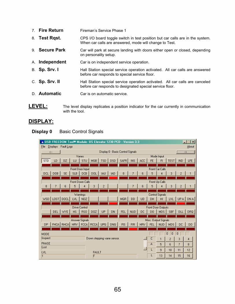
65
7. Fire Return Fireman’s Service Phase 1
8. Test Rqst. CPS I/O board toggle switch in test position but car calls are in the system. When car calls are answered, mode will change to Test.
9. Secure Park Car will park at secure landing with doors either open or closed, depending on personality setup.
A. Independent Car is on independent service operation.
B. Sp. Srv. I Hall Station special service operation activated. All car calls are answered before car responds to special service floor.
C. Sp. Srv. II Hall Station special service operation activated. All car calls are canceled before car responds to designated special service floor.
D. Automatic Car is on automatic service.
LEVEL: The level display replicates a position indicator for the car currently in communication
with the tool.
DISPLAY:
Display 0 Basic Control Signals
66
Vanes Mode Input
STD Down stepping vane SAFR Car Safety String LD Level Down Vane INS Inspection DZ Door Zone Vane ACC Access LU Level Up Vane FE Fireman’s Emergency Return – Phase 1 STU Up stepping vane FI Fireman’s Independent – Phase 2 MGB Pump motor TEST Test TSD Top slow down inactive IND Independent Service DSD Down slow down inactive LFE Lobby Fire – Alternate Fire Service
Front Door Input Front Car Calls
DCL Front Door Close Limit 8 8th Landing Car Call DOB Front Door Open Button 7 7th Landing Car Call SE Front Safety Edge 6 6th Landing Car Call SLB Front Safety Ray 5 5th Landing Car Call DCB Front Door Close Button 4 4th Landing Car Call DOL Front Door Open Limit 3 3rd Landing Car Call IAU Inspection/Access up command 2 2nd Landing Car Call IAD Inspection/Access down command 1 1st Landing Car Call
Front Down Calls Front Up Calls
8 8th Landing Down Hall Call - 7 7th Landing Down Hall Call 7 7th Landing Up Hall Call 6 6th Landing Down Hall Call 6 6th Landing Up Hall Call 5 5th Landing Down Hall Call 5 5th Landing Up Hall Call 4 4th Landing Down Hall Call 4 4th Landing Up Hall Call 3 3rd Landing Down Hall Call 3 3rd Landing Up Hall Call 2 2nd Landing Down Hall Call 2 2nd Landing Up Hall Call - 1 1st Landing Up Hall Call
Warnings Control Signals
WSD Top and Bottom Slowdown Active MGR Motor request LOST Car Lost DD Down direction request DOCL Door Close Limit and Door Close Limit
Active UD Up direction request
LVL Level Up and Level Down Active DH Drop High speed zone NDZ Door zone not found HI High speed request - LVL Level speed Command - UP A Up Arrow - DN A Down Arrow
Drive Control Front Door Outputs
- FEL Fire emergency light DEL Delta signal NUD Nudging buzzer WYE WYE signal DC Close front door HS High speed request DO Open front door RSO Override run/stop switch MDS Modified door speed DOZ Door Open zone SBF Safety ray broken UP Up direction DLL Door lock limit DN Down direction DRQ Door request
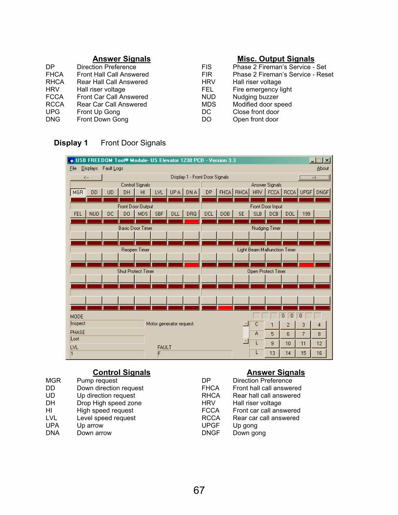
67
Answer Signals Misc. Output Signals
DP Direction Preference FIS Phase 2 Fireman’s Service - Set FHCA Front Hall Call Answered FIR Phase 2 Fireman’s Service - Reset RHCA Rear Hall Call Answered HRV Hall riser voltage HRV Hall riser voltage FEL Fire emergency light FCCA Front Car Call Answered NUD Nudging buzzer RCCA Rear Car Call Answered MDS Modified door speed UPG Front Up Gong DC Close front door DNG Front Down Gong DO Open front door
Display 1 Front Door Signals
Control Signals Answer Signals MGR Pump request DP Direction Preference DD Down direction request FHCA Front hall call answered UD Up direction request RHCA Rear hall call answered DH Drop High speed zone HRV Hall riser voltage HI High speed request FCCA Front car call answered LVL Level speed request RCCA Rear car call answered UPA Up arrow UPGF Up gong DNA Down arrow DNGF Down gong
68
Front Door Output Front Door Inputs
FEL Fire emergency light DCL Door close limit NUD Nudging buzzer DOB Door open button DC Close front door SE Safety edge DO Open front door SLB Safety edge light beam MDS Modified door speed DCB Door close button SBF Safety ray broken DOL Door open limit
DLL Door lock limit 199 Short door time activated (Car call or DCB pressed)
DRQ Door request -
Basic Door Timer Nudging Timer
Time door will be held open in normal operation. Time until nudging operation occurs. (Used if nudging enabled on personality board)
Re-Open Timer Light Beam Malfunction Timer
Time door will remain open after door is forced to reopen.
Time safety ray must remain broken before it is considered bad and ignored.
Door Shut Protect Door Open Protect
Binary count of amount of time door is moved closed before the door is forced open.
Binary count of amount of time door is moved open before the door if forced closed.
69
Display 2 Rear Door Signals
Control Signals Answer Signals MGR Pump request DP Direction Preference DD Down direction request FHCA Front hall call answered UD Up direction request RHCA Rear hall call answered DH Drop High speed zone HRV Hall riser voltage HI High speed request FCCA Front car call answered LVL Level speed request RCCA Rear car call answered UPA Up arrow UPGF Up gong DNA Down arrow DNGF Down gong
Rear Door Output Rear Door Inputs
FEL Fire emergency light DCL Door close limit NUD Nudging buzzer DOB Door open button DC Close front door SE Safety edge DO Open front door SLB Safety edge light beam MDS Modified door speed DCB Door close button SBF Safety ray broken DOL Door open limit
DLL Door lock limit 199 Short door time activated (Car call or DCB pressed)
DRQ Door request -
70
Basic Door Timer Nudging Timer
Time door will be held open in normal operation. Time until nudging operation occurs. (Used if nudging enabled on personality board)
Re-Open Timer Light Beam Malfunction Timer
Time door will remain open after door is forced to reopen.
Time safety ray must remain broken before it is considered bad and ignored.
Door Shut Protect Door Open Protect
Binary count of amount of time door is moved closed before the door is forced open.
Binary count of amount of time door is moved open before the door if forced closed.
71
Display 3 Front / Rear Calls and Signals
Front Door Outputs Rear Door Outputs FEL Fire emergency light FEL Fire emergency light NUD Nudging buzzer NUD Nudging buzzer DC Close front door DC Close rear door DO Open front door DO Open rear door MDS Modified door speed MDS Modified door speed SBF Safety ray broken SBF Safety ray broken DLL Door lock limit DLL Door lock limit DRQ Door request DRQ Door request
Front Door Inputs Rear Door Inputs
DCL Door close limit DCL Door close limit DOB Door open button DOB Door open button SE Safety edge SE Safety edge SLB Safety edge light beam SLB Safety edge light beam DCB Door close button DCB Door close button DOL Door open limit DOL Door open limit
199 Short door time activated (Car call or DCB pressed) 199 Short door time activated (Car call or
DCB pressed) - -
72
Front Car Calls Rear Car Calls
8 8th Landing car call 8 8th Landing car call 7 7th Landing car call 7 7th Landing car call 6 6th landing car call 6 6th landing car call 5 5th landing car call 5 5th landing car call 4 4th landing car call 4 4th landing car call 3 3rd landing car call 3 3rd landing car call 2 2nd landing car call 2 2nd landing car call 1 1st landing car call 1 1st landing car call
Front Up Calls Rear Up Calls
- - 7 7th Landing front up hall call 7 7th Landing rear up hall call 6 6th Landing front up hall call 6 6th Landing rear up hall call 5 5th Landing front up hall call 5 5th Landing rear up hall call 4 4th Landing front up hall call 4 4th Landing rear up hall call 3 3rd Landing front up hall call 3 3rd Landing rear up hall call 2 2nd Landing front up hall call 2 2nd Landing rear up hall call 1 1st Landing front up hall call 1 1st Landing rear up hall call
Front Down Calls Rear Down Calls
8 8th Landing front down hall call 8 8th Landing rear down hall call 7 7th Landing front down hall call 7 7th Landing rear down hall call 6 6th Landing front down hall call 6 6th Landing rear down hall call 5 5th Landing front down hall call 5 5th Landing rear down hall call 4 4th Landing front down hall call 4 4th Landing rear down hall call 3 3rd Landing front down hall call 3 3rd Landing rear down hall call 2 2nd Landing front down hall call 2 2nd Landing rear down hall call - -
Parking & Test Special Services
- - 7 7th Landing call 7 7th Landing call 6 6th landing call 6 6th landing call 5 5th landing call 5 5th landing call 4 4th landing call 4 4th landing call 3 3rd landing call 3 3rd landing call 2 2nd landing call 2 2nd landing call 1 1st landing call 1 1st landing call
73
Display 4 Sequencing and Group Controls
Control Signals Drive Controls MGR Pump request - DD Down direction request DEL Command to energize Delta relay UD Up direction request WYE Command to energize WYE relay DH Drop High speed zone HS High speed request HI High speed request RSO Override run/stop switch LVL Level speed request DOZ Override safety string in Door zone UPA Up arrow UP Command to run car Up DNA Down arrow DN Command to run car Down
Group Inputs Group Outputs
ZB1 Car B Data – Bit 1 MSL Group dispatching data ZB0 Car B Data – Bit 0 ASL Car in Automatic or attendant ZA1 Car A Data – Bit 1 ZS1 Group dispatching data – Bit 1 ZA0 Car A Data – Bit 0 ZS0 Group dispatching data – Bit 0
MSB Car B Data Signal EPD Car must respond to emergency power operation
MSA Car A Data Signal STR Car attempting to engage WYE starter ASB Car B on Automatic or attendant SEQ Emergency power duty car ASA Car A on Automatic or attendant -
74
Sequencing Inputs Call assignment, Car 1
STB Car B start request - SQA Emergency power duty car selected RD Rear call assigned STA Car A start request FD Front call assigned
EPL Car must respond to emergency power operation DN Down call assigned
EPE Car available as duty car UP Up call assigned PRK Car on Secure parking POS1 Position of assigned call - Bit 1 EPO Emergency power operation POS2 Position of assigned call - Bit 2 RESC Rescue Elevator Operation POS3 Position of assigned call - Bit 3
Cars in Automatic Call assignment, Car 2
- - - RD Rear call assigned - FD Front call assigned - DN Down call assigned - UP Up call assigned - POS1 Position of assigned call - Bit 1 2 Number of cars on automatic – Bit 2 POS2 Position of assigned call - Bit 2 1 Number of cars on automatic – Bit 1 POS3 Position of assigned call - Bit 3
Automatic Status of Cars Call assignment, Car 3
- - - RD Rear call assigned - FD Front call assigned - DN Down call assigned - UP Up call assigned 3 Car 3 available for group dispatch POS1 Position of assigned call - Bit 1 2 Car 2 available for group dispatch POS2 Position of assigned call - Bit 2 1 Car 1 available for group dispatch POS3 Position of assigned call - Bit 3
Flags Flags
WYE WYE starter requested NUD Both slow down switches active simultaneously
LW Loadweigher – Car is full SSE Car is lost
FR Fire Return door code has occurred SHF Both door open and door close limits active
FAN Transmit front door answer bit FDZ Both level up and level down sensors active
EPL Car has responded on Emergency Power Return EOP Door zone vane not detected when
expected NA Car not on automatic or attendant HC Car communication rate
BUZ Attendant Service – Attendant notification buzzer GO Software may restart
MSR Master car BAD Group communication timeout
75
Display 5 Fault Information
Control Signals Answer Signals MGR Motor request DP Direction Preference UD Up direction request FHCA Front hall call answered DD Down direction request RHCA Rear hall call answered - HRV Hall riser voltage HI High speed request FCCA Front car call answered SDL Level speed request RCCA Rear car call answered UP A Up arrow UPGF Up gong DN A Down arrow DNGF Down gong
Attendant / Loading Inputs Mode Input
FIHD Fireman’s Service – Phase II – Hold Switch SAFR Safe to run signal
ATCC Attendant service – Call cancel INS Inspection switch inactive ATEX Attendant service – Express ACC Access switch ATT Attendant service FE Fireman’s service – Phase I - FI Fireman’s service – Phase II LDR Loading operation rear TEST Test switch LW Load weigher – full car IND Independent service LDF Loading operation front LFE Fireman’s service – lobby fire detector

76
Front Door Input Rear Door Input
DCL Door close limit DCL Door close limit DOB Door open button DOB Door open button SE Safety edge SE Safety edge SLB Safety edge light beam SLB Safety edge light beam DCB Door close button DCB Door close button DOL Door open limit DOL Door open limit IAU Independent/Access Up IAU Independent/Access Up IAD Independent/Access Down IAD Independent/Access Down
Front Door Outputs Rear Door Outputs
FEL Fire emergency light FEL Fire emergency light NUD Nudging buzzer NUD Nudging buzzer DC Close front door DC Close front door DO Open front door DO Open front door MDS Modified door speed MDS Modified door speed SBF Safety ray broken SBF Safety ray broken DLL Door lock limit DLL Door lock limit DRQ Door request DRQ Door request
Vane Signals Drive Control
STD Down stepping vane - LD Level down vane DEL Command to energize Delta relay DZ Door zone sensor WYE Command to energize WYE relay LU Level up vane HS High speed request STU Up stepping vane RSO Override run/stop switch MGB Pump motor DOZ Override safety string in Door zone TSD Top slow down inactive UP Command to run car up DSD Down slow down inactive DN Command to run car down
Faults Warnings
MLT Motor limit timer WSD Both slow down switches active simultaneously
PERS Incorrect personality jumper positions LOST Car is lost
RLVL Excessive re-levels DOCL Both door open and door close limits active
RP Reverse phase relay drop LVL Both level up and level down sensors active
- NDZ Door zone vane not detected when expected
- - - - - -
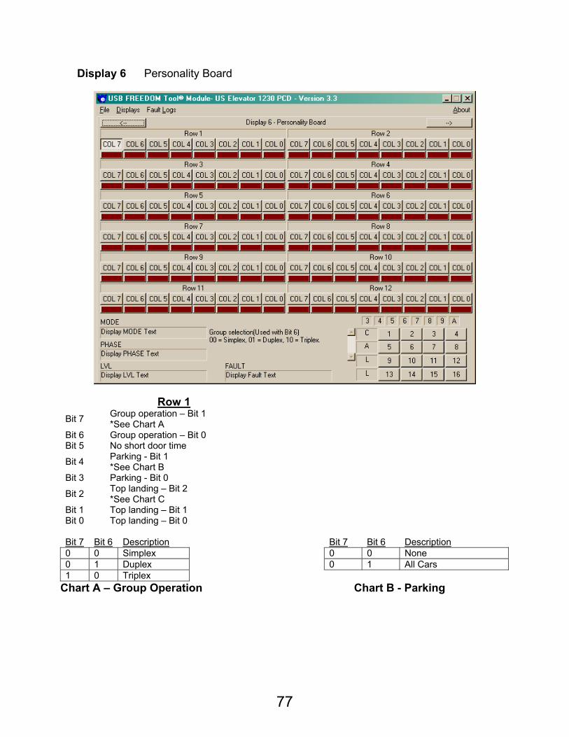
77
Display 6 Personality Board
Row 1 Bit 7 Group operation – Bit 1
*See Chart A Bit 6 Group operation – Bit 0 Bit 5 No short door time
Bit 4 Parking - Bit 1 *See Chart B
Bit 3 Parking - Bit 0
Bit 2 Top landing – Bit 2 *See Chart C
Bit 1 Top landing – Bit 1 Bit 0 Top landing – Bit 0
Bit 7 Bit 6 Description Bit 7 Bit 6 Description 0 0 Simplex 0 0 None 0 1 Duplex 0 1 All Cars 1 0 Triplex
Chart A – Group Operation Chart B - Parking
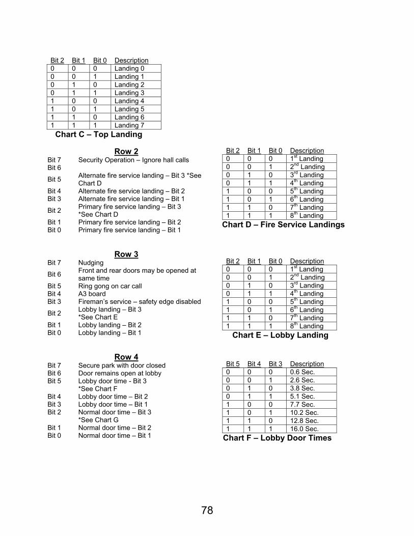
78
Bit 2 Bit 1 Bit 0 Description 0 0 0 Landing 0 0 0 1 Landing 1 0 1 0 Landing 2 0 1 1 Landing 3 1 0 0 Landing 4 1 0 1 Landing 5 1 1 0 Landing 6 1 1 1 Landing 7
Chart C – Top Landing
Row 2 Bit 7 Security Operation – Ignore hall calls Bit 6
Bit 5 Alternate fire service landing – Bit 3 *See Chart D
Bit 4 Alternate fire service landing – Bit 2 Bit 3 Alternate fire service landing – Bit 1
Bit 2 Primary fire service landing – Bit 3 *See Chart D
Bit 1 Primary fire service landing – Bit 2 Bit 0 Primary fire service landing – Bit 1
Bit 2 Bit 1 Bit 0 Description 0 0 0 1st Landing 0 0 1 2nd Landing 0 1 0 3rd Landing 0 1 1 4th Landing 1 0 0 5th Landing 1 0 1 6th Landing 1 1 0 7th Landing 1 1 1 8th Landing
Chart D – Fire Service Landings
Row 3
Bit 7 Nudging
Bit 6 Front and rear doors may be opened at same time
Bit 5 Ring gong on car call Bit 4 A3 board Bit 3 Fireman’s service – safety edge disabled
Bit 2 Lobby landing – Bit 3 *See Chart E
Bit 1 Lobby landing – Bit 2 Bit 0 Lobby landing – Bit 1
Bit 2 Bit 1 Bit 0 Description 0 0 0 1st Landing 0 0 1 2nd Landing 0 1 0 3rd Landing 0 1 1 4th Landing 1 0 0 5th Landing 1 0 1 6th Landing 1 1 0 7th Landing 1 1 1 8th Landing
Chart E – Lobby Landing
Row 4
Bit 7 Secure park with door closed Bit 6 Door remains open at lobby Bit 5 Lobby door time - Bit 3
*See Chart F Bit 4 Lobby door time – Bit 2 Bit 3 Lobby door time – Bit 1 Bit 2 Normal door time – Bit 3
*See Chart G Bit 1 Normal door time – Bit 2 Bit 0 Normal door time – Bit 1
Bit 5 Bit 4 Bit 3 Description 0 0 0 0.6 Sec. 0 0 1 2.6 Sec. 0 1 0 3.8 Sec. 0 1 1 5.1 Sec. 1 0 0 7.7 Sec. 1 0 1 10.2 Sec. 1 1 0 12.8 Sec. 1 1 1 16.0 Sec.
Chart F – Lobby Door Times
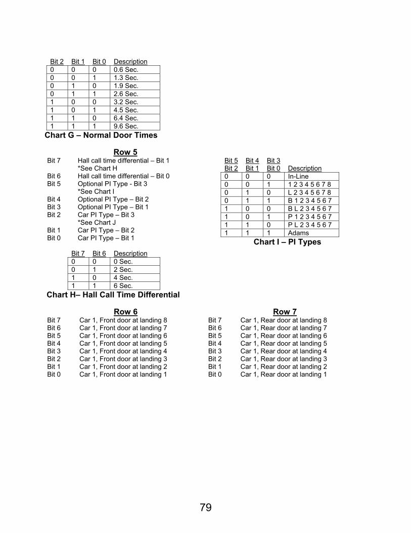
79
Bit 2 Bit 1 Bit 0 Description 0 0 0 0.6 Sec. 0 0 1 1.3 Sec. 0 1 0 1.9 Sec. 0 1 1 2.6 Sec. 1 0 0 3.2 Sec. 1 0 1 4.5 Sec. 1 1 0 6.4 Sec. 1 1 1 9.6 Sec.
Chart G – Normal Door Times
Row 5 Bit 7 Hall call time differential – Bit 1
*See Chart H Bit 6 Hall call time differential – Bit 0 Bit 5 Optional PI Type - Bit 3
*See Chart I Bit 4 Optional PI Type – Bit 2 Bit 3 Optional PI Type – Bit 1 Bit 2 Car PI Type – Bit 3
*See Chart J Bit 1 Car PI Type – Bit 2 Bit 0 Car PI Type – Bit 1
Bit 7 Bit 6 Description 0 0 0 Sec. 0 1 2 Sec. 1 0 4 Sec. 1 1 6 Sec.
Chart H– Hall Call Time Differential
Bit 5 Bit 4 Bit 3 Bit 2 Bit 1 Bit 0 Description 0 0 0 In-Line 0 0 1 1 2 3 4 5 6 7 8 0 1 0 L 2 3 4 5 6 7 8 0 1 1 B 1 2 3 4 5 6 7 1 0 0 B L 2 3 4 5 6 7 1 0 1 P 1 2 3 4 5 6 7 1 1 0 P L 2 3 4 5 6 7 1 1 1 Adams
Chart I – PI Types
Row 6 Row 7
Bit 7 Car 1, Front door at landing 8 Bit 7 Car 1, Rear door at landing 8 Bit 6 Car 1, Front door at landing 7 Bit 6 Car 1, Rear door at landing 7 Bit 5 Car 1, Front door at landing 6 Bit 5 Car 1, Rear door at landing 6 Bit 4 Car 1, Front door at landing 5 Bit 4 Car 1, Rear door at landing 5 Bit 3 Car 1, Front door at landing 4 Bit 3 Car 1, Rear door at landing 4 Bit 2 Car 1, Front door at landing 3 Bit 2 Car 1, Rear door at landing 3 Bit 1 Car 1, Front door at landing 2 Bit 1 Car 1, Rear door at landing 2 Bit 0 Car 1, Front door at landing 1 Bit 0 Car 1, Rear door at landing 1
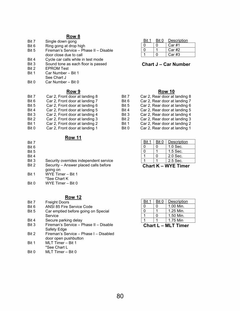
80
Row 8 Bit 7 Single down gong Bit 6 Ring gong at drop high Bit 5 Fireman’s Service – Phase II – Disable
door close due to call Bit 4 Cycle car calls while in test mode Bit 3 Sound tone as each floor is passed Bit 2 EPROM Test Bit 1 Car Number – Bit 1
See Chart J Bit 0 Car Number – Bit 0
Bit 1 Bit 0 Description 0 0 Car #1 0 1 Car #2 1 0 Car #3
Chart J – Car Number
Row 9 Row 10
Bit 7 Car 2, Front door at landing 8 Bit 7 Car 2, Rear door at landing 8 Bit 6 Car 2, Front door at landing 7 Bit 6 Car 2, Rear door at landing 7 Bit 5 Car 2, Front door at landing 6 Bit 5 Car 2, Rear door at landing 6 Bit 4 Car 2, Front door at landing 5 Bit 4 Car 2, Rear door at landing 5 Bit 3 Car 2, Front door at landing 4 Bit 3 Car 2, Rear door at landing 4 Bit 2 Car 2, Front door at landing 3 Bit 2 Car 2, Rear door at landing 3 Bit 1 Car 2, Front door at landing 2 Bit 1 Car 2, Rear door at landing 2 Bit 0 Car 2, Front door at landing 1 Bit 0 Car 2, Rear door at landing 1
Row 11
Bit 7 Bit 6 Bit 5 Bit 4 Bit 3 Security overrides independent service Bit 2 Security – Answer placed calls before
going on Bit 1 WYE Timer – Bit 1
*See Chart K Bit 0 WYE Timer – Bit 0
Bit 1 Bit 0 Description 0 0 1.0 Sec. 0 1 1.5 Sec. 1 0 2.0 Sec. 1 1 2.5 Sec.
Chart K – WYE Timer
Row 12 Bit 7 Freight Doors Bit 6 ANSI 85 Fire Service Code Bit 5 Car emptied before going on Special
Service Bit 4 Secure parking delay Bit 3 Fireman’s Service – Phase II – Disable
Safety Edge Bit 2 Fireman’s Service – Phase I – Disabled
door open pushbutton Bit 1 MLT Timer – Bit 1
*See Chart L Bit 0 MLT Timer – Bit 0
Bit 1 Bit 0 Description 0 0 1.00 Min. 0 1 1.25 Min. 1 0 1.50 Min. 1 1 1.75 Min
Chart L – MLT Timer
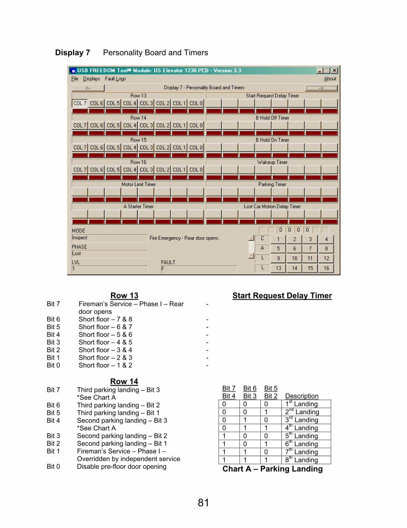
81
Display 7 Personality Board and Timers
Row 13 Start Request Delay Timer
Bit 7 Fireman’s Service – Phase I – Rear door opens
-
Bit 6 Short floor – 7 & 8 - Bit 5 Short floor – 6 & 7 - Bit 4 Short floor – 5 & 6 - Bit 3 Short floor – 4 & 5 - Bit 2 Short floor – 3 & 4 - Bit 1 Short floor – 2 & 3 - Bit 0 Short floor – 1 & 2 -
Row 14
Bit 7 Third parking landing – Bit 3 *See Chart A
Bit 6 Third parking landing – Bit 2 Bit 5 Third parking landing – Bit 1 Bit 4 Second parking landing – Bit 3
*See Chart A Bit 3 Second parking landing – Bit 2 Bit 2 Second parking landing – Bit 1 Bit 1 Fireman’s Service – Phase I –
Overridden by independent service Bit 0 Disable pre-floor door opening
Bit 7 Bit 6 Bit 5 Bit 4 Bit 3 Bit 2 Description 0 0 0 1st Landing 0 0 1 2nd Landing 0 1 0 3rd Landing 0 1 1 4th Landing 1 0 0 5th Landing 1 0 1 6th Landing 1 1 0 7th Landing 1 1 1 8th Landing
Chart A – Parking Landing
82
B Hold Off Timer Row 15
- Bit 7 Car 3, Front door at landing 8 - Bit 6 Car 3, Front door at landing 7 - Bit 5 Car 3, Front door at landing 6 - Bit 4 Car 3, Front door at landing 5 - Bit 3 Car 3, Front door at landing 4 - Bit 2 Car 3, Front door at landing 3 - Bit 1 Car 3, Front door at landing 2 - Bit 0 Car 3, Front door at landing 1
B Hold On Timer Row 16
- Bit 7 Car 3, Rear door at landing 8 - Bit 6 Car 3, Rear door at landing 7 - Bit 5 Car 3, Rear door at landing 6 - Bit 4 Car 3, Rear door at landing 5 - Bit 3 Car 3, Rear door at landing 4 - Bit 2 Car 3, Rear door at landing 3 - Bit 1 Car 3, Rear door at landing 2 - Bit 0 Car 3, Rear door at landing 1
Wakeup Timer Motor Limit Timer
- -
Parking Timer A Starter Timer - -
Lost Car Motion Delay
- -
83
Display 8 Timers
Wye Count Beep on Step - -
Hold Door Closed Group Communication
- -
No Motion Test Call Delay @ Floor - -
Delta Without MGB Attendant Service Call
- -
Special Service Restart - -
Front Gong Rear Gong
- -
84
US Elevator Ascension 1000
FAULT:
0. EPROM An error was detected with the elevator software or RAM memory.
1. EPROM An error was detected with the elevator software or RAM memory.
2. EPROM An error was detected with the elevator software or RAM memory.
3. EPROM An error was detected with the elevator software or RAM memory.
4. Warning A non-volatile fault has occurred. This type of fault will not cause the car to shut down.
5. Motor Limit Motor limit timer has expired. Car will run to terminal landing and stay there with doors open.
6. Personality An error is detected with personality settings. Car will stop where it is.
7. Run Fail Car has failed to start six times in twenty seconds. Car will run to bottom landing and sit with doors open.
8. Reverse Phase Reverse phase relay has dropped. Car will run to bottom landing and sit with doors open.
PHASE: The following is a list of phases of the run the Ascension 1000 controller may have.
0. Fault A fault was detected while car was running.
1. Shutdown Car has shutdown.
2. Lost Car has lost its position within the hoistway.
3. Wakeup Car is just starting.
4. Rest Car is parked at landing.
5. Relevel Down Car is releveling into a landing in the down direction.
6. Recover Down Car is running down to the next level to recover from fault.
7. Level Down Car is running at leveling speed in the down direction.
8. High Down Car is running at high speed in the down direction.
9. Relevel Up Car is releveling into a landing in the up direction.
A. Recover Up Car is running up to the next level to recover from fault.
B. Level Up Car is running at leveling speed in the up direction.
C. High Up Car is running at high speed in the up direction.
85
MODE: The following is a list of modes of operation that the Ascension 1000 controller may have. They are listed in order of priority, with the top mode having highest priority.
0. Restart Car CPU in a restart state.
1. Inspect Inspection operation.
2. Access Hoistway Access.
3. Fire Ind. Fireman’s Service Phase 2.
4. Fault System contains a fault. Fault display – Stop Now has occurred.
5. Test CPS I/O board toggle switch in test position (down).
6. Emerg. Power Car is on emergency power operation. Generator is providing main car power.
7. Fire Return Fireman’s Service Phase 1
8. Test Rqst. CPS I/O board toggle switch in test position but car calls are in the system. When car calls are answered, mode will change to Test.
9. Secure Park Car will park at secure landing with doors either open or closed, depending on personality setup.
A. Independent Car is on independent service operation.
B. Sp. Srv. I Hall Station special service operation activated. All car calls are answered before car responds to special service floor.
C. Sp. Srv. II Hall Station special service operation activated. All car calls are canceled before car responds to designated special service floor.
D. Automatic Car is on automatic service.
LEVEL: The level display replicates a position indicator for the car currently in communication with the tool.
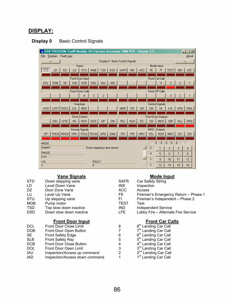
86
DISPLAY:
Display 0 Basic Control Signals
Vane Signals Mode Input STD Down stepping vane SAFR Car Safety String LD Level Down Vane INS Inspection DZ Door Zone Vane ACC Access LU Level Up Vane FE Fireman’s Emergency Return – Phase 1 STU Up stepping vane FI Fireman’s Independent – Phase 2 MGB Pump motor TEST Test TSD Top slow down inactive IND Independent Service DSD Down slow down inactive LFE Lobby Fire – Alternate Fire Service
Front Door Input Front Car Calls
DCL Front Door Close Limit 8 8th Landing Car Call DOB Front Door Open Button 7 7th Landing Car Call SE Front Safety Edge 6 6th Landing Car Call SLB Front Safety Ray 5 5th Landing Car Call DCB Front Door Close Button 4 4th Landing Car Call DOL Front Door Open Limit 3 3rd Landing Car Call IAU Inspection/Access up command 2 2nd Landing Car Call IAD Inspection/Access down command 1 1st Landing Car Call
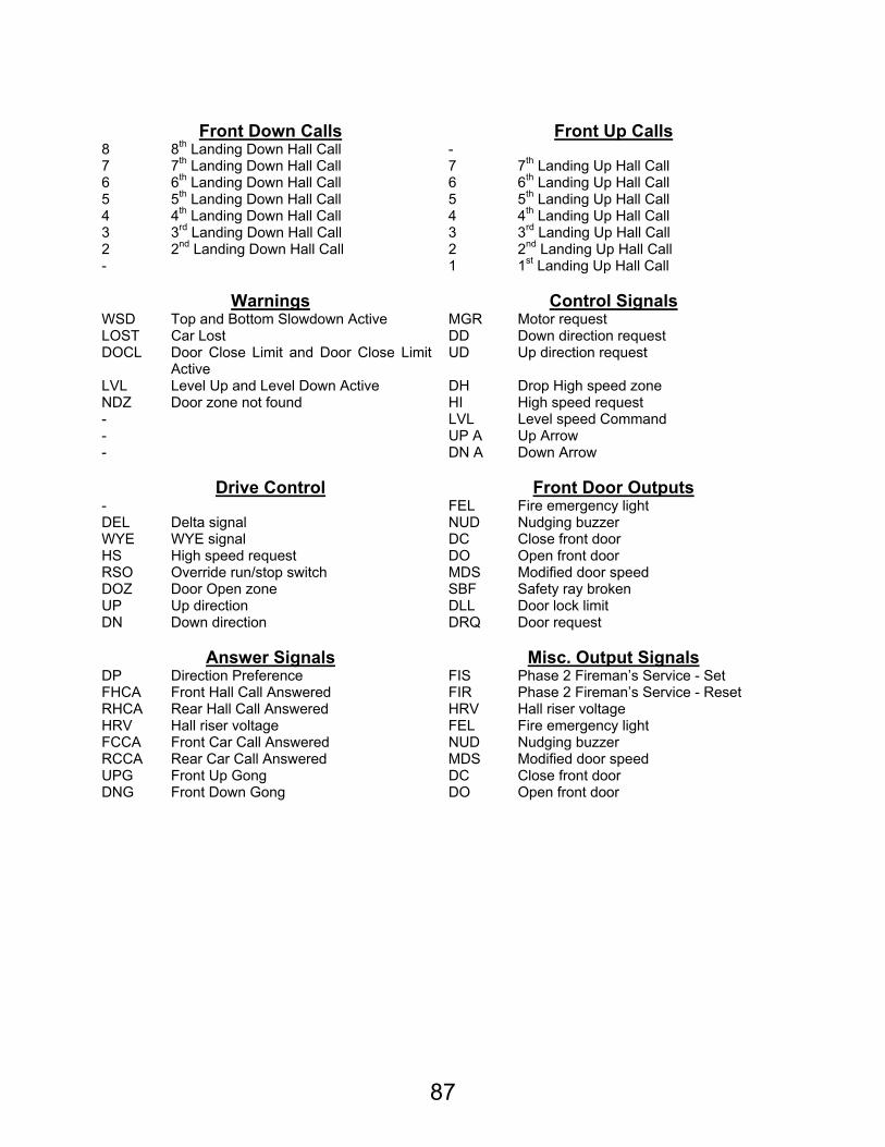
87
Front Down Calls Front Up Calls
8 8th Landing Down Hall Call - 7 7th Landing Down Hall Call 7 7th Landing Up Hall Call 6 6th Landing Down Hall Call 6 6th Landing Up Hall Call 5 5th Landing Down Hall Call 5 5th Landing Up Hall Call 4 4th Landing Down Hall Call 4 4th Landing Up Hall Call 3 3rd Landing Down Hall Call 3 3rd Landing Up Hall Call 2 2nd Landing Down Hall Call 2 2nd Landing Up Hall Call - 1 1st Landing Up Hall Call
Warnings Control Signals
WSD Top and Bottom Slowdown Active MGR Motor request LOST Car Lost DD Down direction request DOCL Door Close Limit and Door Close Limit
Active UD Up direction request
LVL Level Up and Level Down Active DH Drop High speed zone NDZ Door zone not found HI High speed request - LVL Level speed Command - UP A Up Arrow - DN A Down Arrow
Drive Control Front Door Outputs
- FEL Fire emergency light DEL Delta signal NUD Nudging buzzer WYE WYE signal DC Close front door HS High speed request DO Open front door RSO Override run/stop switch MDS Modified door speed DOZ Door Open zone SBF Safety ray broken UP Up direction DLL Door lock limit DN Down direction DRQ Door request
Answer Signals Misc. Output Signals
DP Direction Preference FIS Phase 2 Fireman’s Service - Set FHCA Front Hall Call Answered FIR Phase 2 Fireman’s Service - Reset RHCA Rear Hall Call Answered HRV Hall riser voltage HRV Hall riser voltage FEL Fire emergency light FCCA Front Car Call Answered NUD Nudging buzzer RCCA Rear Car Call Answered MDS Modified door speed UPG Front Up Gong DC Close front door DNG Front Down Gong DO Open front door
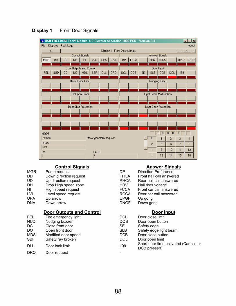
88
Display 1 Front Door Signals
Control Signals Answer Signals MGR Pump request DP Direction Preference DD Down direction request FHCA Front hall call answered UD Up direction request RHCA Rear hall call answered DH Drop High speed zone HRV Hall riser voltage HI High speed request FCCA Front car call answered LVL Level speed request RCCA Rear car call answered UPA Up arrow UPGF Up gong DNA Down arrow DNGF Down gong
Door Outputs and Control Door Input
FEL Fire emergency light DCL Door close limit NUD Nudging buzzer DOB Door open button DC Close front door SE Safety edge DO Open front door SLB Safety edge light beam MDS Modified door speed DCB Door close button SBF Safety ray broken DOL Door open limit
DLL Door lock limit 199 Short door time activated (Car call or DCB pressed)
DRQ Door request -
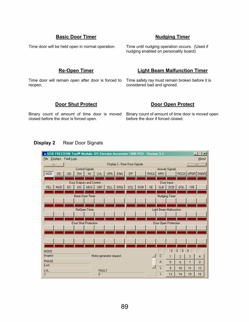
89
Basic Door Timer Nudging Timer
Time door will be held open in normal operation. Time until nudging operation occurs. (Used if
nudging enabled on personality board)
Re-Open Timer Light Beam Malfunction Timer Time door will remain open after door is forced to reopen.
Time safety ray must remain broken before it is considered bad and ignored.
Door Shut Protect Door Open Protect Binary count of amount of time door is moved closed before the door is forced open.
Binary count of amount of time door is moved open before the door if forced closed.
Display 2 Rear Door Signals
90
Control Signals Answer Signals
MGR Pump request DP Direction Preference DD Down direction request FHCA Front hall call answered UD Up direction request RHCA Rear hall call answered DH Drop High speed zone HRV Hall riser voltage HI High speed request FCCA Front car call answered LVL Level speed request RCCA Rear car call answered UPA Up arrow UPGF Up gong DNA Down arrow DNGF Down gong
Door Outputs and Control Door Input
FEL Fire emergency light DCL Door close limit NUD Nudging buzzer DOB Door open button DC Close rear door SE Safety edge DO Open rear door SLB Safety edge light beam MDS Modified door speed DCB Door close button SBF Safety ray broken DOL Door open limit
DLL Door lock limit 199 Short door time activated (Car call or DCB pressed)
DRQ Door request -
Basic Door Timer Nudging Timer Time door will be held open in normal operation. Time until nudging operation occurs. (Used if
nudging enabled on personality board)
Re-Open Timer Light Beam Malfunction Timer Time door will remain open after door is forced to reopen.
Time safety ray must remain broken before it is considered bad and ignored.
Door Shut Protect Door Open Protect Binary count of amount of time door is moved closed before the door is forced open.
Binary count of amount of time door is moved open before the door if forced closed.
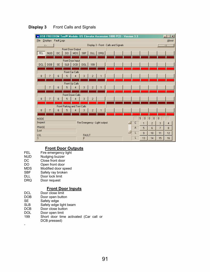
91
Display 3 Front Calls and Signals
Front Door Outputs FEL Fire emergency light NUD Nudging buzzer DC Close front door DO Open front door MDS Modified door speed SBF Safety ray broken DLL Door lock limit DRQ Door request
Front Door Inputs
DCL Door close limit DOB Door open button SE Safety edge SLB Safety edge light beam DCB Door close button DOL Door open limit 199 Short door time activated (Car call or
DCB pressed)
-

92
Front Car Calls
8 8th Landing car call 7 7th Landing car call 6 6th landing car call 5 5th landing car call 4 4th landing car call 3 3rd landing car call 2 2nd landing car call 1 1st landing car call
Front Up Calls
- 7 7th Landing front up hall call 6 6th Landing front up hall call 5 5th Landing front up hall call 4 4th Landing front up hall call 3 3rd Landing front up hall call 2 2nd Landing front up hall call 1 1st Landing front up hall call
Front Down Calls
8 8th Landing front down hall call 7 7th Landing front down hall call 6 6th Landing front down hall call 5 5th Landing front down hall call 4 4th Landing front down hall call 3 3rd Landing front down hall call 2 2nd Landing front down hall call -
Parking and Test Calls
- 7 7th Landing call 6 6th landing call 5 5th landing call 4 4th landing call 3 3rd landing call 2 2nd landing call 1 1st landing call
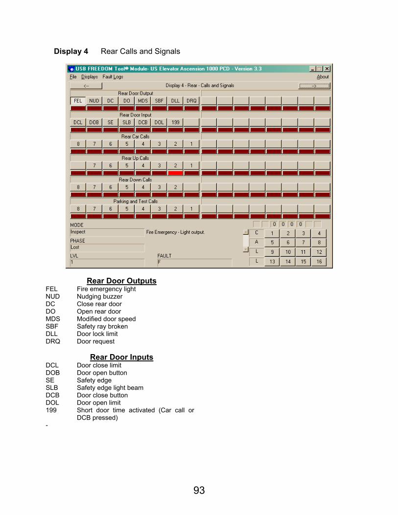
93
Display 4 Rear Calls and Signals
Rear Door Outputs FEL Fire emergency light NUD Nudging buzzer DC Close rear door DO Open rear door MDS Modified door speed SBF Safety ray broken DLL Door lock limit DRQ Door request
Rear Door Inputs
DCL Door close limit DOB Door open button SE Safety edge SLB Safety edge light beam DCB Door close button DOL Door open limit 199 Short door time activated (Car call or
DCB pressed)
-
94
Rear Car Calls
8 8th Landing car call 7 7th Landing car call 6 6th Landing car call 5 5th Landing car call 4 4th Landing car call 3 3rd Landing car call 2 2nd Landing car call 1 1st Landing car call
Rear Up Calls
- 7 7th Landing rear up hall call 6 6th Landing rear up hall call 5 5th Landing rear up hall call 4 4th Landing rear up hall call 3 3rd Landing rear up hall call 2 2nd Landing rear up hall call 1 1st Landing rear up hall call
Rear Down Calls
8 8th Landing rear down hall call 7 7th Landing rear down hall call 6 6th Landing rear down hall call 5 5th Landing rear down hall call 4 4th Landing rear down hall call 3 3rd Landing rear down hall call 2 2nd Landing rear down hall call -
Parking and Test Calls
- 7 7th Landing call 6 6th Landing call 5 5th Landing call 4 4th Landing call 3 3rd Landing call 2 2nd Landing call 1 1st Landing call
95
Display 5 Fault Information
Control Signals Answer Signals MGR Motor request DP Direction Preference UD Up direction request FHCA Front hall call answered DD Down direction request RHCA Rear hall call answered - HRV Hall riser voltage HI High speed request FCCA Front car call answered SDL Level speed request RCCA Rear car call answered UP A Up arrow UPGF Up gong DN A Down arrow DNGF Down gong
Attendant / Loading Inputs Mode Input
FIHD Fireman’s Service – Phase II – Hold Switch SAFR Safe to run signal
ATCC Attendant service – Call cancel INS Inspection switch inactive ATEX Attendant service – Express ACC Access switch ATT Attendant service FE Fireman’s service – Phase I - FI Fireman’s service – Phase II LDR Loading operation rear TEST Test switch LW Load weigher – full car IND Independent service LDF Loading operation front LFE Fireman’s service – lobby fire detector
96
Front Door Input Rear Door Input
DCL Door close limit DCL Door close limit DOB Door open button DOB Door open button SE Safety edge SE Safety edge SLB Safety edge light beam SLB Safety edge light beam DCB Door close button DCB Door close button DOL Door open limit DOL Door open limit IAU Independent/Access Up IAU Independent/Access Up IAD Independent/Access Down IAD Independent/Access Down
Front Door Outputs Rear Door Outputs
FEL Fire emergency light FEL Fire emergency light NUD Nudging buzzer NUD Nudging buzzer DC Close front door DC Close rear door DO Open front door DO Open rear door MDS Modified door speed MDS Modified door speed SBF Safety ray broken SBF Safety ray broken DLL Door lock limit DLL Door lock limit DRQ Door request DRQ Door request
Vane Signals Drive Control
STD Down stepping vane - LD Level down vane DEL Command to energize Delta relay DZ Door zone sensor WYE Command to energize WYE relay LU Level up vane HS High speed request STU Up stepping vane RSO Override run/stop switch MGB Pump motor DOZ Override safety string in Door zone TSD Top slow down inactive UP Command to run car up DSD Down slow down inactive DN Command to run car down
Faults Warnings
MLT Motor limit timer WSD Both slow down switches active simultaneously
PERS Incorrect personality jumper positions LOST Car is lost
RLVL Excessive re-levels DOCL Both door open and door close limits active
RP Reverse phase relay drop LVL Both level up and level down sensors active
- NDZ Door zone vane not detected when expected
- - - - - -
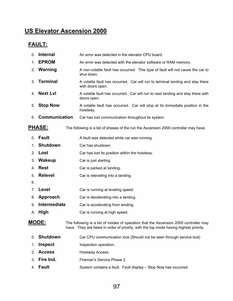
97
US Elevator Ascension 2000
FAULT:
0. Internal An error was detected in the elevator CPU board.
1. EPROM An error was detected with the elevator software or RAM memory.
2. Warning A non-volatile fault has occurred. This type of fault will not cause the car to shut down.
3. Terminal A volatile fault has occurred. Car will run to terminal landing and stay there with doors open.
4. Next Lvl A volatile fault has occurred. Car will run to next landing and stay there with doors open.
5. Stop Now A volatile fault has occurred. Car will stop at its immediate position in the hoistway.
6. Communication Car has lost communication throughout its system.
PHASE: The following is a list of phases of the run the Ascension 2000 controller may have.
0. Fault A fault was detected while car was running.
1. Shutdown Car has shutdown.
2. Lost Car has lost its position within the hoistway.
3. Wakeup Car is just starting.
4. Rest Car is parked at landing.
5. Relevel Car is releveling into a landing.
6.
7. Level Car is running at leveling speed.
8. Approach Car is decelerating into a landing.
9. Intermediate Car is accelerating from landing.
A. High Car is running at high speed.
MODE: The following is a list of modes of operation that the Ascension 2000 controller may have. They are listed in order of priority, with the top mode having highest priority.
0. Shutdown Car CPU communication lock (Should not be seen through service tool)
1. Inspect Inspection operation.
2. Access Hoistway Access.
3. Fire Ind. Fireman’s Service Phase 2.
4. Fault System contains a fault. Fault display – Stop Now has occurred.
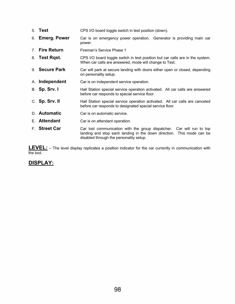
98
5. Test CPS I/O board toggle switch in test position (down).
6. Emerg. Power Car is on emergency power operation. Generator is providing main car power.
7. Fire Return Fireman’s Service Phase 1
8. Test Rqst. CPS I/O board toggle switch in test position but car calls are in the system. When car calls are answered, mode will change to Test.
9. Secure Park Car will park at secure landing with doors either open or closed, depending on personality setup.
A. Independent Car is on independent service operation.
B. Sp. Srv. I Hall Station special service operation activated. All car calls are answered before car responds to special service floor.
C. Sp. Srv. II Hall Station special service operation activated. All car calls are canceled before car responds to designated special service floor.
D. Automatic Car is on automatic service.
E. Attendant Car is on attendant operation.
F. Street Car Car lost communication with the group dispatcher. Car will run to top landing and stop each landing in the down direction. This mode can be disabled through the personality setup.
LEVEL: – The level display replicates a position indicator for the car currently in communication with the tool.
DISPLAY:
99
Display 0 General Car Status Display
Control Signals Answer Signals MGR Motor request DP Direction Preference UD Up direction request FHCA Front Hall Call Answered DD Down direction request RHCA Rear Hall Call Answered - DH Drop High speed zone HI High speed request FCCA Front Car Call Answered SDL Level speed request RCCA Rear Car Call Answered UP A Up Arrow UPGF Front Up Gong DN A Down Arrow DNGF Front Down Gong
Speed Control Drive Control
- UP Up direction - DN Down direction HX High Speed Indicator WYE WYE signal HI High Speed Command DEL Delta signal INT Intermediate Speed Command - AP Approach Speed Command INSP Inspection - DOZ Door Open zone LVL Level speed Command PRD Power drive
100
Front Door Input Rear Door Input
LOAD Front Load Switch LOAD Rear Load Switch - - DCB Front Door Close Button DCB Rear Door Close Button DOB Front Door Open Button DOB Rear Door Open Button DCL Front Door Close Limit DCL Rear Door Close Limit DOL Front Door Open Limit DOL Rear Door Open Limit SE Front Safety Edge SE Rear Safety Edge SLB Front Safety Ray SLB Rear Safety Ray
Vanes Mode Input
- SAFR Car Safety String - INS Inspection - ACC Access - FE Fireman’s Emergency Return – Phase 1 LD Level Down Vane FI Fireman’s Independent – Phase 2 DZ Door Zone Vane TEST Test LU Level Up Vane RDC Redundancy Monitor - LFE Lobby Fire – Alternate Fire Service
Mode Input Terminal Slowdown
WYEA WYE Status MGR Motor Request FIOF Car Station Fire Switch Off RP 3 Phase Status PARK Secure Park - EPO Emergency Power - - T1U Up Slowdown Switch - T1D Down Slowdown Switch DM Door Monitor UDL Up Directional Limit HFR Houston Fire Service DDL Down Directional Limit
Travel Indicator Calls
- 8 8th Landing Car Call - 7 7th Landing Car Call - 6 6th Landing Car Call - 5 5th Landing Car Call - 4 4th Landing Car Call - 3 3rd Landing Car Call - 2 2nd Landing Car Call - 1 1st Landing Car Call
101
Display 1 Fault Information
Control Signals Answer Signals MGR Motor request DP Direction Preference UD Up direction request FHCA Front Hall Call Answered DD Down direction request RHCA Rear Hall Call Answered - DH Drop High speed zone HI High speed request FCCA Front Car Call Answered SDL Level speed request RCCA Rear Car Call Answered UP A Up Arrow UPGF Front Up Gong DN A Down Arrow DNGF Front Down Gong
Speed Control Drive Control
- UP Up direction - DN Down direction HX High Speed Indicator WYE WYE signal HI High Speed Command DEL Delta signal INT Intermediate Speed Command - AP Approach Speed Command INSP Inspection - DOZ Door Open zone LVL Level speed Command PRD Power drive
102
Front Door Input Rear Door Input
LOAD Front Load Switch LOAD Rear Load Switch - - DCB Front Door Close Button DCB Rear Door Close Button DOB Front Door Open Button DOB Rear Door Open Button DCL Front Door Close Limit DCL Rear Door Close Limit DOL Front Door Open Limit DOL Rear Door Open Limit SE Front Safety Edge SE Rear Safety Edge SLB Front Safety Ray SLB Rear Safety Ray
Vanes Mode Input
- SAFR Car Safety String - INS Inspection - ACC Access - FE Fireman’s Emergency Return – Phase 1 LD Level Down Vane FI Fireman’s Independent – Phase 2 DZ Door Zone Vane TEST Test LU Level Up Vane RDC Redundancy Monitor - LFE Lobby Fire – Alternate Fire Service
Stop Immediately Recoverable
FDOZ Door Open Zone Self Check Failure LEAK Relevel counter overflow - PERS Personality Fault PHCG Phase Change RP Reverse Phase Check - MLT Motor Limit Timer FDM Door Monitor Fault - FRDC Redundancy Fault LULD Level Up/Level Down - RLVL Relevel Fault CPS CPS Data Fault -
Run to Next Level Warnings
- TSD Top and Bottom Slowdown Active - LOST Car Lost - DOCL Door Close Limit and Door Close Limit
Active - LVL Level Up and Level Down Active - DLIM Direction Limit - DLCK Door Lock - NOVN No Vane NOLV No Level Vane CSC Car Station Communication
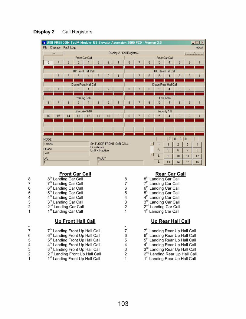
103
Display 2 Call Registers
Front Car Call Rear Car Call 8 8th Landing Car Call 8 8th Landing Car Call 7 7th Landing Car Call 7 7th Landing Car Call 6 6th Landing Car Call 6 6th Landing Car Call 5 5th Landing Car Call 5 5th Landing Car Call 4 4th Landing Car Call 4 4th Landing Car Call 3 3rd Landing Car Call 3 3rd Landing Car Call 2 2nd Landing Car Call 2 2nd Landing Car Call 1 1st Landing Car Call 1 1st Landing Car Call
Up Front Hall Call Up Rear Hall Call
- - 7 7th Landing Front Up Hall Call 7 7th Landing Rear Up Hall Call 6 6th Landing Front Up Hall Call 6 6th Landing Rear Up Hall Call 5 5th Landing Front Up Hall Call 5 5th Landing Rear Up Hall Call 4 4th Landing Front Up Hall Call 4 4th Landing Rear Up Hall Call 3 3rd Landing Front Up Hall Call 3 3rd Landing Rear Up Hall Call 2 2nd Landing Front Up Hall Call 2 2nd Landing Rear Up Hall Call 1 1st Landing Front Up Hall Call 1 1st Landing Rear Up Hall Call
104
Down Front Hall Call Down Rear Hall Call
8 8th Landing Front Down Hall Call 8 8th Landing Rear Down Hall Call 7 7th Landing Front Down Hall Call 7 7th Landing Rear Down Hall Call 6 6th Landing Front Down Hall Call 6 6th Landing Rear Down Hall Call 5 5th Landing Front Down Hall Call 5 5th Landing Rear Down Hall Call 4 4th Landing Front Down Hall Call 4 4th Landing Rear Down Hall Call 3 3rd Landing Front Down Hall Call 3 3rd Landing Rear Down Hall Call 2 2nd Landing Front Down Hall Call 2 2nd Landing Rear Down Hall Call - -
Parking Calls Test Calls
8 Car requested to park at 8th landing 8 Test call placed at 8th landing 7 Car requested to park at 7th landing 7 Test call placed at 7th landing 6 Car requested to park at 6th landing 6 Test call placed at 6th landing 5 Car requested to park at 5th landing 5 Test call placed at 5th landing 4 Car requested to park at 4th landing 4 Test call placed at 4th landing 3 Car requested to park at 3rd landing 3 Test call placed at 3rd landing 2 Car requested to park at 2nd landing 2 Test call placed at 2nd landing 1 Car requested to park at 1st landing 1 Test call placed at 1st landing
Stop Immediately Recoverable
FDOZ Door Open Zone Self Check Failure LEAK Relevel counter overflow - PERS Personality Fault PHCG Phase Change RP Reverse Phase Check - MLT Motor Limit Timer FDM Door Monitor Fault - FRDC Redundancy Fault LULD Level Up/Level Down - RLVL Relevel Fault CPS CPS Data Fault -
Security 9 – 16 Security 1 – 8
16 16th landing enabled through security 8 8th landing enabled through security 15 15th landing enabled through security 7 7th landing enabled through security 14 14th landing enabled through security 6 6th landing enabled through security 13 13th landing enabled through security 5 5th landing enabled through security 12 12th landing enabled through security 4 4th landing enabled through security 11 11th landing enabled through security 3 3rd landing enabled through security 10 10th landing enabled through security 2 2nd landing enabled through security 9 9th landing enabled through security 1 1st landing enabled through security
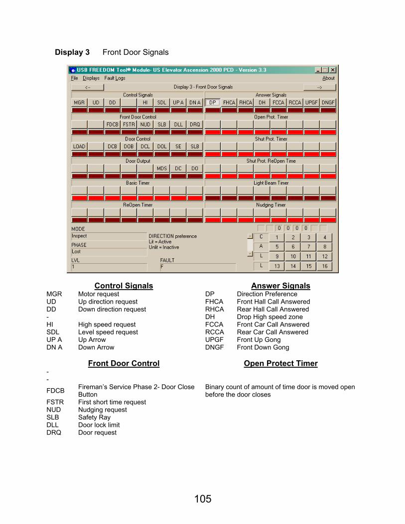
105
Display 3 Front Door Signals
Control Signals Answer Signals MGR Motor request DP Direction Preference UD Up direction request FHCA Front Hall Call Answered DD Down direction request RHCA Rear Hall Call Answered - DH Drop High speed zone HI High speed request FCCA Front Car Call Answered SDL Level speed request RCCA Rear Car Call Answered UP A Up Arrow UPGF Front Up Gong DN A Down Arrow DNGF Front Down Gong
Front Door Control Open Protect Timer
- -
FDCB Fireman’s Service Phase 2- Door Close Button
FSTR First short time request
Binary count of amount of time door is moved open before the door closes
NUD Nudging request SLB Safety Ray DLL Door lock limit DRQ Door request

106
Front Door Control Shut Protect Timer
LOAD Front Load Switch - DCB Front Door Close Button DOB Front Door Open Button
Binary count of amount of time door is moved closed before the door opens.
DCL Front Door Close Limit DOL Front Door Open Limit SE Front Safety Edge SLB Front Safety Ray
Door Output Shut Protect Re-Open Timer
- - - -
Binary count of amount of time door reopens after shut protect timer expires
- MDS Modified door speed DC Close front door DO Open front door
Basic Timer Light Beam Timer
Binary count of how long the door will normally stay open
Binary count of how long the light beam is activated before it is considered faulty and ignored
Re-Open Timer Nudging Timer Binary count of how long door will stay open after a reopen
Binary count of how long doors will remain open before nudging operation engages.
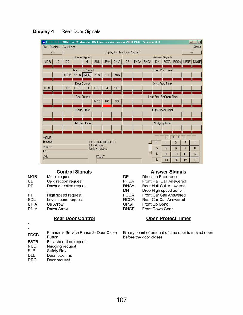
107
Display 4 Rear Door Signals
Control Signals Answer Signals MGR Motor request DP Direction Preference UD Up direction request FHCA Front Hall Call Answered DD Down direction request RHCA Rear Hall Call Answered - DH Drop High speed zone HI High speed request FCCA Front Car Call Answered SDL Level speed request RCCA Rear Car Call Answered UP A Up Arrow UPGF Front Up Gong DN A Down Arrow DNGF Front Down Gong
Rear Door Control Open Protect Timer
- -
FDCB Fireman’s Service Phase 2- Door Close Button
FSTR First short time request
Binary count of amount of time door is moved open before the door closes
NUD Nudging request SLB Safety Ray DLL Door lock limit DRQ Door request
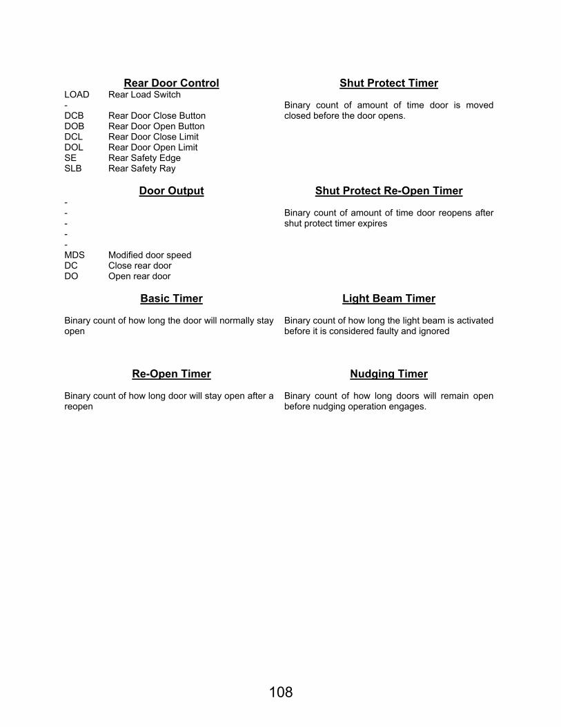
108
Rear Door Control Shut Protect Timer
LOAD Rear Load Switch - DCB Rear Door Close Button DOB Rear Door Open Button
Binary count of amount of time door is moved closed before the door opens.
DCL Rear Door Close Limit DOL Rear Door Open Limit SE Rear Safety Edge SLB Rear Safety Ray
Door Output Shut Protect Re-Open Timer
- - - -
Binary count of amount of time door reopens after shut protect timer expires
- MDS Modified door speed DC Close rear door DO Open rear door
Basic Timer Light Beam Timer
Binary count of how long the door will normally stay open
Binary count of how long the light beam is activated before it is considered faulty and ignored
Re-Open Timer Nudging Timer Binary count of how long door will stay open after a reopen
Binary count of how long doors will remain open before nudging operation engages.
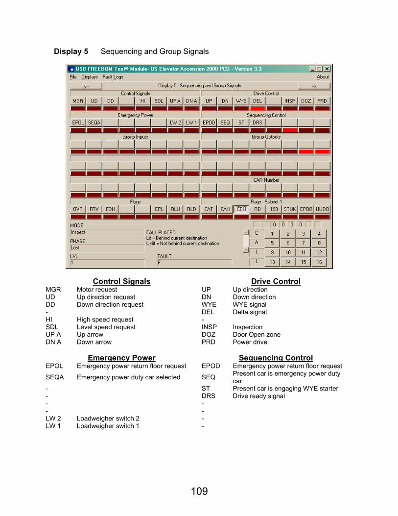
109
Display 5 Sequencing and Group Signals
Control Signals Drive Control MGR Motor request UP Up direction UD Up direction request DN Down direction DD Down direction request WYE WYE signal - DEL Delta signal HI High speed request - SDL Level speed request INSP Inspection UP A Up arrow DOZ Door Open zone DN A Down arrow PRD Power drive
Emergency Power Sequencing Control
EPOL Emergency power return floor request EPOD Emergency power return floor request
SEQA Emergency power duty car selected SEQ Present car is emergency power duty car
- ST Present car is engaging WYE starter - DRS Drive ready signal - - - - LW 2 Loadweigher switch 2 - LW 1 Loadweigher switch 1 -
110
Group Inputs Group Outputs
Car Number
Car number assigned to this car through personality
Flags Flags – Subset 1 OVR Overshoot CAT Call placed at current car level FRV First vane CAH Call placed ahead of car’s destination FDH Force drop high zone CBH Call placed behind car’s destination - RD Rear door enabled - 199 Car call/Door open button pressed
EPL Car has responded to emergency power service landing STUK Front door stuck
RLU Relevel last occurred in up direction EPOO Emergency power - Door open request
RLD Relevel last occurred in down direction HUDO Houston fire service – Door open request
Display 6 General Inputs
111
Landing 1 High Byte Landing 1 Low Byte
Binary indication of upper byte of landing 1 position Binary indication of lower byte of landing 1 position.
Landing 2 High Byte Landing 2 Low Byte Binary indication of upper byte of landing 2 position Binary indication of lower byte of landing 2 position.
Landing 3 High Byte Landing 3 Low Byte Binary indication of upper byte of landing 3 position Binary indication of lower byte of landing 3 position.
Landing 4 High Byte Landing 4 Low Byte Binary indication of upper byte of landing 4 position Binary indication of lower byte of landing 4 position.
Landing 5 High Byte Landing 5 Low Byte Binary indication of upper byte of landing 5 position Binary indication of lower byte of landing 5 position.
Landing 6 High Byte Landing 6 Low Byte Binary indication of upper byte of landing 6 position Binary indication of lower byte of landing 6 position.
112
Display 7 General Inputs
CCU 1 LO CCU 1 HI ACC Access SAFR Car safety string WYEA Another car in WYE operation DZ Door zone vane INS Inspection DOLF Front door open limit RP Reverse phase check IAU Inspection/Access up direction RDC Redundancy monitor - FE Fireman’s service – Phase 1 IAD Inspection/Access down direction - DM Door monitor FI Fireman’s service – Phase 2 LFE Lobby Fire – Alternate Fire Service
CCU 2 LO CCU 4 LO
- SEC 8 Landing 8 security operation TEST Test SEC 7 Landing 7 security operation CPSR0 CPS head data SEC 6 Landing 6 security operation CPSR0 CPS head data SEC 5 Landing 5 security operation CPSC3 CPS count data SEC 4 Landing 4 security operation CPSC2 CPS count data SEC 3 Landing 3 security operation CPSC1 CPS count data SEC 2 Landing 2 security operation CPSC0 CPS count data SEC 1 Landing 1 security operation
113
CCU 3 HI CCU 3 LO
16 Hall call # 16 8 Hall call # 08 15 Hall call # 15 7 Hall call # 07 14 Hall call # 14 6 Hall call # 06 13 Hall call # 13 5 Hall call # 05 12 Hall call # 12 4 Hall call # 04 11 Hall call # 11 3 Hall call # 03 10 Hall call # 10 2 Hall call # 02 9 Hall call # 09 1 Hall call # 01
CSU 1 LO CSU 1 HI
FIOF Phase 2 Fireman’s Service - Off SLBF Front Safety Ray FHLD Phase 2 Fireman’s Service - Hold SEF Front Safety Edge FICR Phase 2 Fireman’s Service - Call Reset DCB Front Door Close Button TS1D Bottom Terminal Slowdown DOB Front Door Open Button LVLU Level Up Sensor DCL Front Door Close Limit DZ Door Zone Sensor DOL Front Door Open Limit LVLD Level Down Sensor LOAD Front Load Switch TS1U Top Terminal Slowdown IND Independent Service
CSU 2 LO CSU 2 HI
8 Car call # 08 SLBR Rear Safety Ray 7 Car call # 07 SE Rear Safety Edge 6 Car call # 06 DCB Rear Door Close Button 5 Car call # 05 DOB Rear Door Open Button 4 Car call # 04 DCL Rear Door Close Limit 3 Car call # 03 DOL Rear Door Open Limit 2 Car call # 02 LOAD Rear Load Switch 1 Car call # 01 -
CSU 3 LO CSU 4 HI
16 Car call # 16 EMT Emergency medical car switch 15 Car call # 15 SPRK Secure parking 14 Car call # 14 EMTH Emergency medical hall switch 13 Car call # 13 ATT Attendant service 12 Car call # 12 ATEX Attendant service – Express 11 Car call # 11 ATCC Attendant service – Call cancel 10 Car call # 10 SWCR Swing car service 9 Car call # 09 -
114
Display 8 Optional Input signals
CCU 1 LO CCU 1 HI HS High speed HRV Hall riser voltage - FIS Phase 2 Fireman’s Service - Set DNX Down direction auxiliary FIR Phase 2 Fireman’s Service - Reset DEL Delta starter signal DOZ Door override zone - RSO Run/Stop override UPX Up direction auxiliary DN Down direction - UP Up direction - WYE WYE starter signal
CCU 2 LO CCU 2 HI
LVL8 Car at landing 8 - LVL7 Car at landing 7 - LVL6 Car at landing 6 DNGR Rear down gong LVL5 Car at landing 5 UPGR Rear up gong LVL4 Car at landing 4 DNGF Front down gong LVL3 Car at landing 3 UPGF Front up gong LVL2 Car at landing 2 DNA Down arrow LVL1 Car at landing 1 UPA Up arrow
115
CCU 3 HI CCU 3 LO
HC09 Hall call # 09 HC01 Hall call # 01 HC10 Hall call # 10 HC02 Hall call # 02 HC11 Hall call # 11 HC03 Hall call # 03 HC12 Hall call # 12 HC04 Hall call # 04 HC13 Hall call # 13 HC05 Hall call # 05 HC14 Hall call # 14 HC06 Hall call # 06 HC15 Hall call # 15 HC07 Hall call # 07 HC16 Hall call # 16 HC08 Hall call # 08
CSU 1 LO CSU 1 HI
- MDSF Front door modified speed FEL Fire emergency light DCF Front door close signal DNA Down arrow DOF Front door open signal UPA Up arrow NUD Nudging buzzer CPI3 Car position Bit 3 DNGF Front down gong CPI2 Car position Bit 2 UPGF Front up gong CPI1 Car position Bit 1 LTFN Light/Fan Timeout CPI0 Car position Bit 0 -
CSU 2 LO CSU 2 HI
CC08 Car call # 08 MDSR Rear door modified speed CC07 Car call # 07 DCR Rear door close signal CC06 Car call # 06 DOR Rear door open signal CC05 Car call # 05 NUDQ Rear door nudging buzzer CC04 Car call # 04 DNGR Rear down gong CC03 Car call # 03 UPGR Rear up gong CC02 Car call # 02 - CC01 Car call # 01 -
CSU 3 LO CSU 4 HI
CC16 Car call # 16 AUTO Automatic operation CC15 Car call # 15 FLT Fault signal CC14 Car call # 14 - CC13 Car call # 13 - CC12 Car call # 12 - CC11 Car call # 11 - CC10 Car call # 10 - CC09 Car call # 09 -
PERSONALITY: Displays 9 and A are the personality displays. This personality information are adjustments/settings/features of the elevator system that are adjustable using the service tool. Display 9 and A are the only displays that allow the changing of information. To navigate through these windows, pushbuttons are made available to the user in the lower right-hand corner of the display. Notice that the call pushbutton and status indicators are removed from this window. When the user wants to change a personality bit use the following:
1) Press the GRP(E) pushbutton to get the FOCUS LED flashing. The FOCUS LED is the one currently receiving the focus of the input buttons SET(1) and CLR(0).
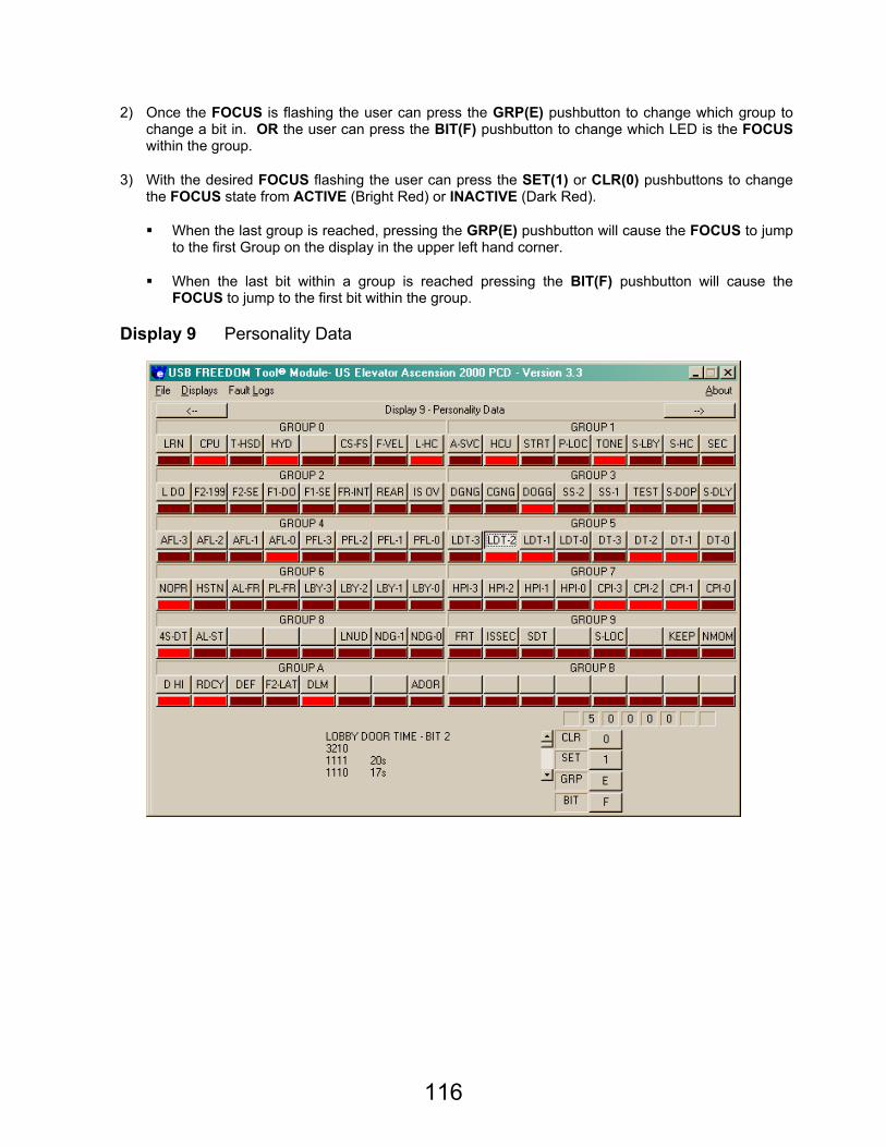
116
2) Once the FOCUS is flashing the user can press the GRP(E) pushbutton to change which group to change a bit in. OR the user can press the BIT(F) pushbutton to change which LED is the FOCUS within the group.
3) With the desired FOCUS flashing the user can press the SET(1) or CLR(0) pushbuttons to change the FOCUS state from ACTIVE (Bright Red) or INACTIVE (Dark Red).
When the last group is reached, pressing the GRP(E) pushbutton will cause the FOCUS to jump to the first Group on the display in the upper left hand corner.
When the last bit within a group is reached pressing the BIT(F) pushbutton will cause the FOCUS to jump to the first bit within the group.
Display 9 Personality Data
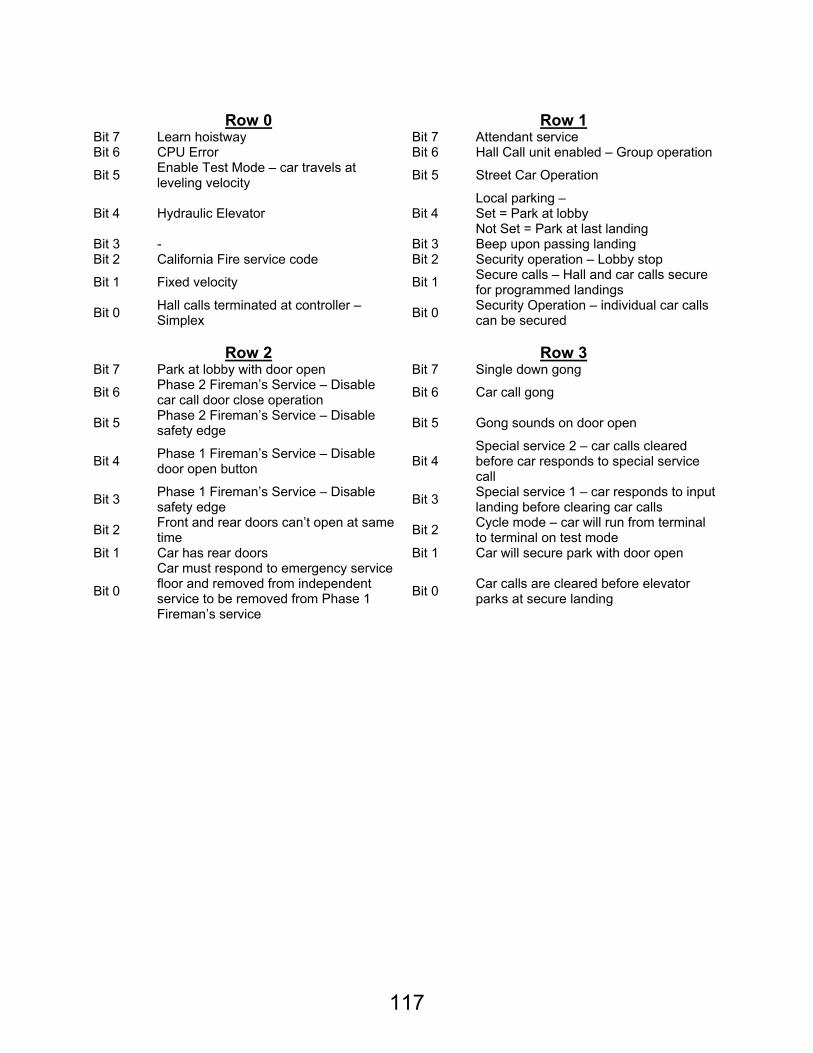
117
Row 0 Row 1
Bit 7 Learn hoistway Bit 7 Attendant service Bit 6 CPU Error Bit 6 Hall Call unit enabled – Group operation
Bit 5 Enable Test Mode – car travels at leveling velocity Bit 5 Street Car Operation
Bit 4 Hydraulic Elevator Bit 4 Local parking – Set = Park at lobby Not Set = Park at last landing
Bit 3 - Bit 3 Beep upon passing landing Bit 2 California Fire service code Bit 2 Security operation – Lobby stop
Bit 1 Fixed velocity Bit 1 Secure calls – Hall and car calls secure for programmed landings
Bit 0 Hall calls terminated at controller – Simplex Bit 0 Security Operation – individual car calls
can be secured
Row 2 Row 3 Bit 7 Park at lobby with door open Bit 7 Single down gong
Bit 6 Phase 2 Fireman’s Service – Disable car call door close operation Bit 6 Car call gong
Bit 5 Phase 2 Fireman’s Service – Disable safety edge Bit 5 Gong sounds on door open
Bit 4 Phase 1 Fireman’s Service – Disable door open button Bit 4
Special service 2 – car calls cleared before car responds to special service call
Bit 3 Phase 1 Fireman’s Service – Disable safety edge Bit 3 Special service 1 – car responds to input
landing before clearing car calls
Bit 2 Front and rear doors can’t open at same time Bit 2 Cycle mode – car will run from terminal
to terminal on test mode Bit 1 Car has rear doors Bit 1 Car will secure park with door open
Bit 0
Car must respond to emergency service floor and removed from independent service to be removed from Phase 1 Fireman’s service
Bit 0 Car calls are cleared before elevator parks at secure landing
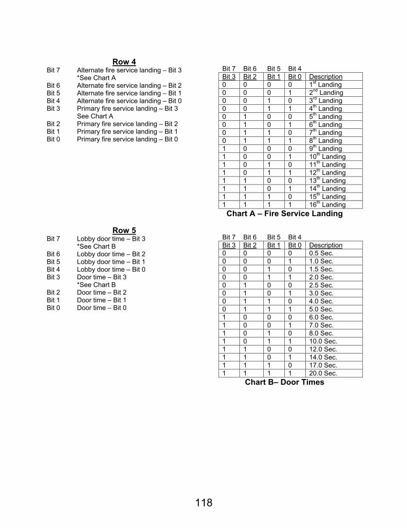
118
Row 4 Bit 7 Alternate fire service landing – Bit 3
*See Chart A Bit 6 Alternate fire service landing – Bit 2 Bit 5 Alternate fire service landing – Bit 1 Bit 4 Alternate fire service landing – Bit 0 Bit 3 Primary fire service landing – Bit 3
See Chart A Bit 2 Primary fire service landing – Bit 2 Bit 1 Primary fire service landing – Bit 1 Bit 0 Primary fire service landing – Bit 0
Bit 7 Bit 6 Bit 5 Bit 4 Bit 3 Bit 2 Bit 1 Bit 0 Description 0 0 0 0 1st Landing 0 0 0 1 2nd Landing 0 0 1 0 3rd Landing 0 0 1 1 4th Landing 0 1 0 0 5th Landing 0 1 0 1 6th Landing 0 1 1 0 7th Landing 0 1 1 1 8th Landing 1 0 0 0 9th Landing 1 0 0 1 10th Landing 1 0 1 0 11th Landing 1 0 1 1 12th Landing 1 1 0 0 13th Landing 1 1 0 1 14th Landing 1 1 1 0 15th Landing 1 1 1 1 16th Landing
Chart A – Fire Service Landing
Row 5 Bit 7 Lobby door time – Bit 3
*See Chart B Bit 6 Lobby door time – Bit 2 Bit 5 Lobby door time – Bit 1 Bit 4 Lobby door time – Bit 0 Bit 3 Door time – Bit 3
*See Chart B Bit 2 Door time – Bit 2 Bit 1 Door time – Bit 1 Bit 0 Door time – Bit 0
Bit 7 Bit 6 Bit 5 Bit 4 Bit 3 Bit 2 Bit 1 Bit 0 Description 0 0 0 0 0.5 Sec. 0 0 0 1 1.0 Sec. 0 0 1 0 1.5 Sec. 0 0 1 1 2.0 Sec. 0 1 0 0 2.5 Sec. 0 1 0 1 3.0 Sec. 0 1 1 0 4.0 Sec. 0 1 1 1 5.0 Sec. 1 0 0 0 6.0 Sec. 1 0 0 1 7.0 Sec. 1 0 1 0 8.0 Sec. 1 0 1 1 10.0 Sec. 1 1 0 0 12.0 Sec. 1 1 0 1 14.0 Sec. 1 1 1 0 17.0 Sec. 1 1 1 1 20.0 Sec.
Chart B– Door Times
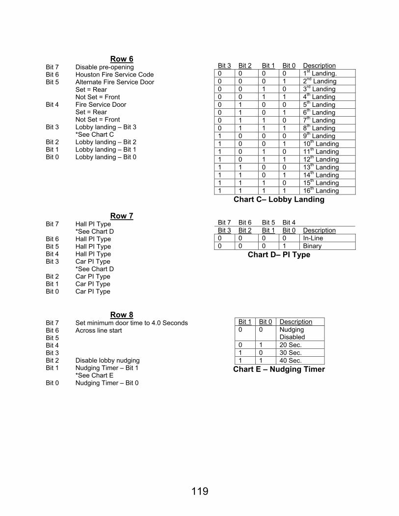
119
Row 6
Bit 7 Disable pre-opening Bit 6 Houston Fire Service Code Bit 5 Alternate Fire Service Door
Set = Rear Not Set = Front
Bit 4 Fire Service Door Set = Rear Not Set = Front
Bit 3 Lobby landing – Bit 3 *See Chart C
Bit 2 Lobby landing – Bit 2 Bit 1 Lobby landing – Bit 1 Bit 0 Lobby landing – Bit 0
Bit 3 Bit 2 Bit 1 Bit 0 Description 0 0 0 0 1st Landing. 0 0 0 1 2nd Landing 0 0 1 0 3rd Landing 0 0 1 1 4th Landing 0 1 0 0 5th Landing 0 1 0 1 6th Landing 0 1 1 0 7th Landing 0 1 1 1 8th Landing 1 0 0 0 9th Landing 1 0 0 1 10th Landing 1 0 1 0 11th Landing 1 0 1 1 12th Landing 1 1 0 0 13th Landing 1 1 0 1 14th Landing 1 1 1 0 15th Landing 1 1 1 1 16th Landing
Chart C– Lobby Landing
Row 7 Bit 7 Hall PI Type
*See Chart D Bit 6 Hall PI Type Bit 5 Hall PI Type Bit 4 Hall PI Type Bit 3 Car PI Type
*See Chart D Bit 2 Car PI Type Bit 1 Car PI Type Bit 0 Car PI Type
Bit 7 Bit 6 Bit 5 Bit 4 Bit 3 Bit 2 Bit 1 Bit 0 Description 0 0 0 0 In-Line 0 0 0 1 Binary
Chart D– PI Type
Row 8
Bit 7 Set minimum door time to 4.0 Seconds Bit 6 Across line start Bit 5 Bit 4 Bit 3 Bit 2 Disable lobby nudging Bit 1 Nudging Timer – Bit 1
*See Chart E Bit 0 Nudging Timer – Bit 0
Bit 1 Bit 0 Description 0 0 Nudging
Disabled 0 1 20 Sec. 1 0 30 Sec. 1 1 40 Sec.
Chart E – Nudging Timer
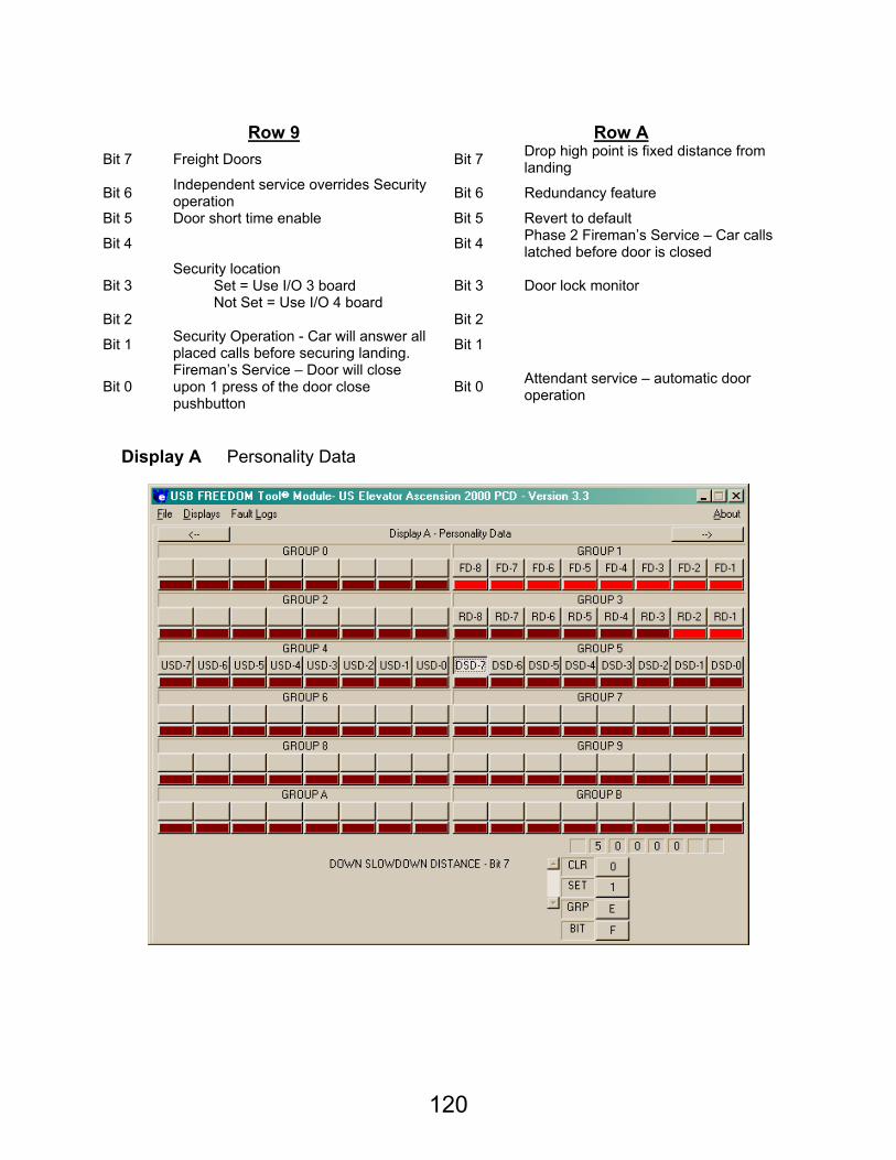
120
Row 9 Row A
Bit 7 Freight Doors Bit 7 Drop high point is fixed distance from landing
Bit 6 Independent service overrides Security operation Bit 6 Redundancy feature
Bit 5 Door short time enable Bit 5 Revert to default
Bit 4 Bit 4 Phase 2 Fireman’s Service – Car calls latched before door is closed
Bit 3 Security location Set = Use I/O 3 board Not Set = Use I/O 4 board
Bit 3 Door lock monitor
Bit 2 Bit 2
Bit 1 Security Operation - Car will answer all placed calls before securing landing. Bit 1
Bit 0 Fireman’s Service – Door will close upon 1 press of the door close pushbutton
Bit 0 Attendant service – automatic door operation
Display A Personality Data
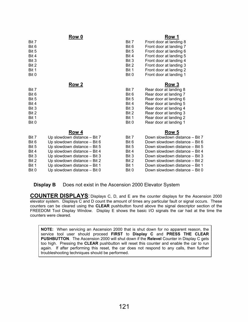
121
Row 0 Row 1
Bit 7 Bit 7 Front door at landing 8 Bit 6 Bit 6 Front door at landing 7 Bit 5 Bit 5 Front door at landing 6 Bit 4 Bit 4 Front door at landing 5 Bit 3 Bit 3 Front door at landing 4 Bit 2 Bit 2 Front door at landing 3 Bit 1 Bit 1 Front door at landing 2 Bit 0 Bit 0 Front door at landing 1
Row 2 Row 3
Bit 7 Bit 7 Rear door at landing 8 Bit 6 Bit 6 Rear door at landing 7 Bit 5 Bit 5 Rear door at landing 6 Bit 4 Bit 4 Rear door at landing 5 Bit 3 Bit 3 Rear door at landing 4 Bit 2 Bit 2 Rear door at landing 3 Bit 1 Bit 1 Rear door at landing 2 Bit 0 Bit 0 Rear door at landing 1
Row 4 Row 5
Bit 7 Up slowdown distance – Bit 7 Bit 7 Down slowdown distance – Bit 7 Bit 6 Up slowdown distance – Bit 6 Bit 6 Down slowdown distance – Bit 6 Bit 5 Up slowdown distance – Bit 5 Bit 5 Down slowdown distance – Bit 5 Bit 4 Up slowdown distance – Bit 4 Bit 4 Down slowdown distance – Bit 4 Bit 3 Up slowdown distance – Bit 3 Bit 3 Down slowdown distance – Bit 3 Bit 2 Up slowdown distance – Bit 2 Bit 2 Down slowdown distance – Bit 2 Bit 1 Up slowdown distance – Bit 1 Bit 1 Down slowdown distance – Bit 1 Bit 0 Up slowdown distance – Bit 0 Bit 0 Down slowdown distance – Bit 0
Display B Does not exist in the Ascension 2000 Elevator System
COUNTER DISPLAYS: Displays C, D, and E are the counter displays for the Ascension 2000 elevator system. Displays C and D count the amount of times any particular fault or signal occurs. These counters can be cleared using the CLEAR pushbutton found above the signal descriptor section of the FREEDOM Tool Display Window. Display E shows the basic I/O signals the car had at the time the counters were cleared.
NOTE: When servicing an Ascension 2000 that is shut down for no apparent reason, the service tool user should proceed FIRST to Display C and PRESS THE CLEAR PUSHBUTTON. The Ascension 2000 will shut down if the Relevel Counter in Display C gets too high. Pressing the CLEAR pushbutton will reset this counter and enable the car to run again. If after performing this reset, the car does not respond to any calls, then further troubleshooting techniques should be performed.
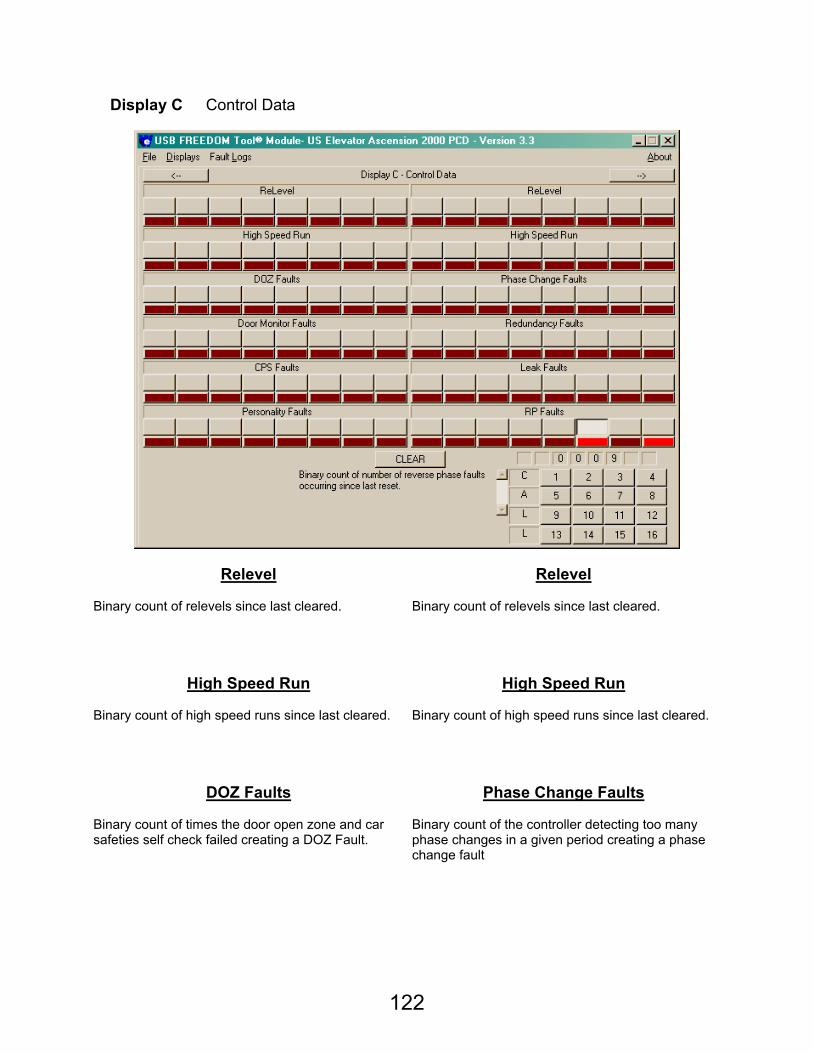
122
Display C Control Data
Relevel Relevel Binary count of relevels since last cleared. Binary count of relevels since last cleared.
High Speed Run High Speed Run Binary count of high speed runs since last cleared. Binary count of high speed runs since last cleared.
DOZ Faults Phase Change Faults Binary count of times the door open zone and car safeties self check failed creating a DOZ Fault.
Binary count of the controller detecting too many phase changes in a given period creating a phase change fault
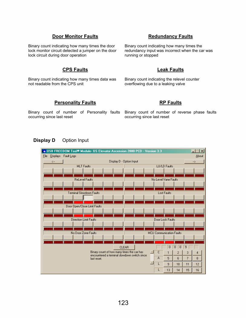
123
Door Monitor Faults Redundancy Faults
Binary count indicating how many times the door lock monitor circuit detected a jumper on the door lock circuit during door operation
Binary count indicating how many times the redundancy input was incorrect when the car was running or stopped
CPS Faults Leak Faults Binary count indicating how many times data was not readable from the CPS unit
Binary count indicating the relevel counter overflowing due to a leaking valve
Personality Faults RP Faults Binary count of number of Personality faults occurring since last reset
Binary count of number of reverse phase faults occurring since last reset
Display D Option Input
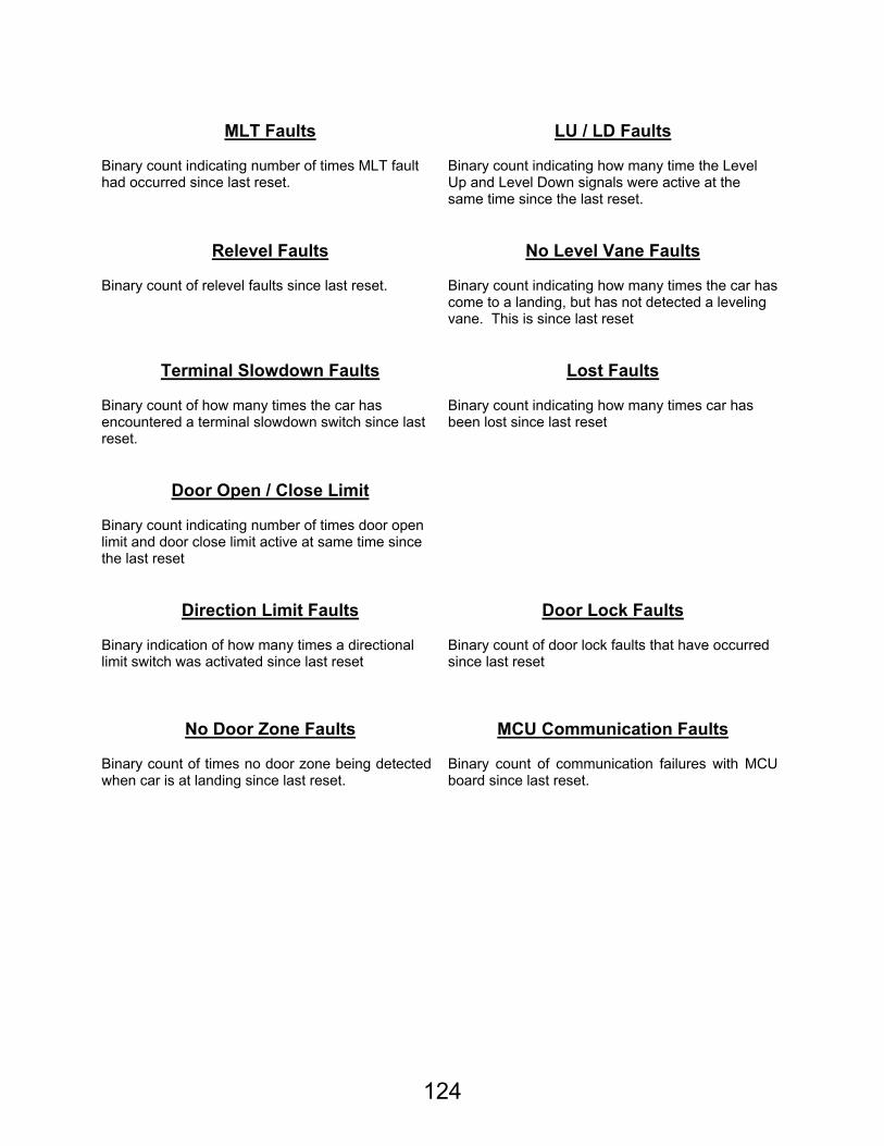
124
MLT Faults LU / LD Faults
Binary count indicating number of times MLT fault had occurred since last reset.
Binary count indicating how many time the Level Up and Level Down signals were active at the same time since the last reset.
Relevel Faults No Level Vane Faults Binary count of relevel faults since last reset. Binary count indicating how many times the car has
come to a landing, but has not detected a leveling vane. This is since last reset
Terminal Slowdown Faults Lost Faults Binary count of how many times the car has encountered a terminal slowdown switch since last reset.
Binary count indicating how many times car has been lost since last reset
Door Open / Close Limit Binary count indicating number of times door open limit and door close limit active at same time since the last reset
Direction Limit Faults Door Lock Faults Binary indication of how many times a directional limit switch was activated since last reset
Binary count of door lock faults that have occurred since last reset
No Door Zone Faults MCU Communication Faults Binary count of times no door zone being detected when car is at landing since last reset.
Binary count of communication failures with MCU board since last reset.
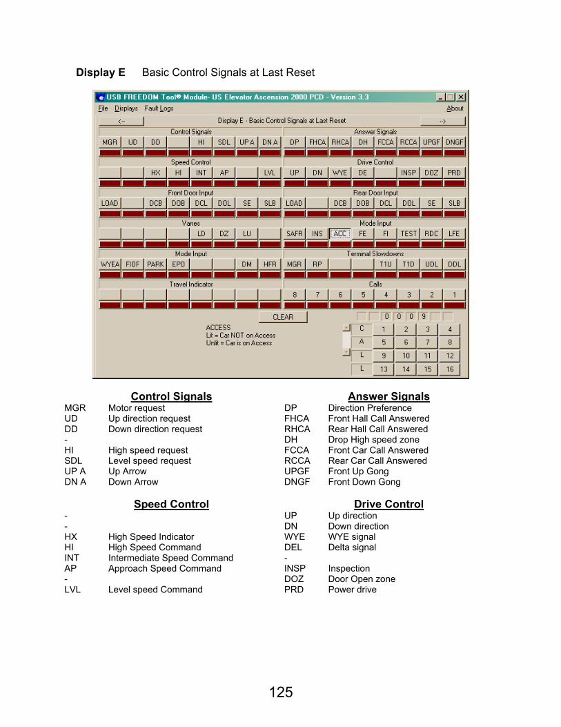
125
Display E Basic Control Signals at Last Reset
Control Signals Answer Signals MGR Motor request DP Direction Preference UD Up direction request FHCA Front Hall Call Answered DD Down direction request RHCA Rear Hall Call Answered - DH Drop High speed zone HI High speed request FCCA Front Car Call Answered SDL Level speed request RCCA Rear Car Call Answered UP A Up Arrow UPGF Front Up Gong DN A Down Arrow DNGF Front Down Gong
Speed Control Drive Control
- UP Up direction - DN Down direction HX High Speed Indicator WYE WYE signal HI High Speed Command DEL Delta signal INT Intermediate Speed Command - AP Approach Speed Command INSP Inspection - DOZ Door Open zone LVL Level speed Command PRD Power drive
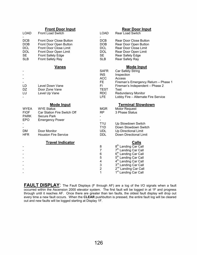
126
Front Door Input Rear Door Input
LOAD Front Load Switch LOAD Rear Load Switch - - DCB Front Door Close Button DCB Rear Door Close Button DOB Front Door Open Button DOB Rear Door Open Button DCL Front Door Close Limit DCL Rear Door Close Limit DOL Front Door Open Limit DOL Rear Door Open Limit SE Front Safety Edge SE Rear Safety Edge SLB Front Safety Ray SLB Rear Safety Ray
Vanes Mode Input
- SAFR Car Safety String - INS Inspection - ACC Access - FE Fireman’s Emergency Return – Phase 1 LD Level Down Vane FI Fireman’s Independent – Phase 2 DZ Door Zone Vane TEST Test LU Level Up Vane RDC Redundancy Monitor - LFE Lobby Fire – Alternate Fire Service
Mode Input Terminal Slowdown
WYEA WYE Status MGR Motor Request FIOF Car Station Fire Switch Off RP 3 Phase Status PARK Secure Park - EPO Emergency Power - - T1U Up Slowdown Switch - T1D Down Slowdown Switch DM Door Monitor UDL Up Directional Limit HFR Houston Fire Service DDL Down Directional Limit
Travel Indicator Calls
- 8 8th Landing Car Call - 7 7th Landing Car Call - 6 6th Landing Car Call - 5 5th Landing Car Call - 4 4th Landing Car Call - 3 3rd Landing Car Call - 2 2nd Landing Car Call - 1 1st Landing Car Call
FAULT DISPLAY: The Fault Displays (F through AF) are a log of the I/O signals when a fault occurred within the Ascension 2000 elevator system. The first fault will be logged in at 1F and progress through until it reaches AF. Once there are greater than ten faults, the oldest fault display will drop out every time a new fault occurs. When the CLEAR pushbutton is pressed, the entire fault log will be cleared out and new faults will be logged starting at Display 1F.
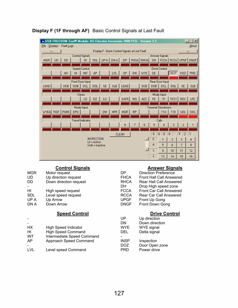
127
Display F (1F through AF) Basic Control Signals at Last Fault
Control Signals Answer Signals MGR Motor request DP Direction Preference UD Up direction request FHCA Front Hall Call Answered DD Down direction request RHCA Rear Hall Call Answered - DH Drop High speed zone HI High speed request FCCA Front Car Call Answered SDL Level speed request RCCA Rear Car Call Answered UP A Up Arrow UPGF Front Up Gong DN A Down Arrow DNGF Front Down Gong
Speed Control Drive Control
- UP Up direction - DN Down direction HX High Speed Indicator WYE WYE signal HI High Speed Command DEL Delta signal INT Intermediate Speed Command - AP Approach Speed Command INSP Inspection - DOZ Door Open zone LVL Level speed Command PRD Power drive

128
Front Door Input Rear Door Input
LOAD Front Load Switch LOAD Rear Load Switch - - DCB Front Door Close Button DCB Rear Door Close Button DOB Front Door Open Button DOB Rear Door Open Button DCL Front Door Close Limit DCL Rear Door Close Limit DOL Front Door Open Limit DOL Rear Door Open Limit SE Front Safety Edge SE Rear Safety Edge SLB Front Safety Ray SLB Rear Safety Ray
Vanes Mode Input
- SAFR Car Safety String - INS Inspection - ACC Access - FE Fireman’s Emergency Return – Phase 1 LD Level Down Vane FI Fireman’s Independent – Phase 2 DZ Door Zone Vane TEST Test LU Level Up Vane RDC Redundancy Monitor - LFE Lobby Fire – Alternate Fire Service
Mode Input Terminal Slowdown
WYEA WYE Status MGR Motor Request FIOF Car Station Fire Switch Off RP 3 Phase Status PARK Secure Park - EPO Emergency Power - - T1U Up Slowdown Switch - T1D Down Slowdown Switch DM Door Monitor UDL Up Directional Limit HFR Houston Fire Service DDL Down Directional Limit
Travel Indicator Calls
- 8 8th Landing Car Call - 7 7th Landing Car Call - 6 6th Landing Car Call - 5 5th Landing Car Call - 4 4th Landing Car Call - 3 3rd Landing Car Call - 2 2nd Landing Car Call - 1 1st Landing Car Call