Embed Size (px)
Citation preview

This guide shows you how to use the provisioning tool
to create projects, set up the segment controller page,
configure TCP/IP, configure GPRS, set control groups,
define and provision devices, create devices, create bulk
devices, and commission your products.
078-0161-01D

Echelon, LumInsight, and the Echelon logo are trademarks of
Echelon Corporation that may be registered in the United
States and other countries.
Other brand and product names are trademarks or
registered trademarks of their respective holders.
Smart Transceivers, Neuron Chips, and other OEM Products
were not designed for use in equipment or systems, which
involve danger to human health or safety, or a risk of
property damage and Echelon assumes no responsibility or
liability for use of the Smart Transceivers or Neuron Chips in
such applications.
Parts manufactured by vendors other than Echelon and
referenced in this document have been described for
illustrative purposes only, and may not have been tested
by Echelon. It is the responsibility of the customer to
determine the suitability of these parts for each
application.
ECHELON MAKES AND YOU RECEIVE NO WARRANTIES OR
CONDITIONS, EXPRESS, IMPLIED, STATUTORY OR IN ANY
COMMUNICATION WITH YOU, AND ECHELON SPECIFICALLY
DISCLAIMS ANY IMPLIED WARRANTY OF MERCHANTABILITY
OR FITNESS FOR A PARTICULAR PURPOSE.
No part of this publication may be reproduced, stored in a
retrieval system, or transmitted, in any form or by any means,
electronic, mechanical, photocopying, recording, or
otherwise, without the prior written permission of Echelon
Corporation.
Printed in the United States of America.
Copyright © 2015 - 2016 Echelon Corporation.
Echelon Corporation
www.echelon.com

Welcome This document describes the features and operation of Echelon’s LumInsight Provisioning Tool.
Audience This guide is intended for LumInsight users who want to use the graphical user interface of the
Provisioning Tool. Use the tool to create LumInsight projects which manage the configuration of
SmartServer based segment controllers in a connected lighting system. The project will define
the segment controller TCP/IP settings, logical group organization, and the devices monitored
and controlled and ultimately managed by the LumInsight CMS.
Examples Throughout this PDF, screen shots will guide you through the process of using the LumInsight
Provisioning Tool.
Related Documentation The following manuals are available from the Echelon Web site (www.echelon.com) and provide
additional information for the LumInsight products.
Title
Part Number
Description
LumInsight CMS Installation Guide
078-0159-01C
This manual helps you install your LumInsight product.
LumInsight Web Portal Tool User’s Guide
078-1060-01D
This manual shows you the dashboard of the LumInsight Web Portal. Use this guide to set up Geozones, update and delete devices, manage alarms, manage group controllers, and troubleshoot your Geozones.
.
LumInsight Provisioning Tool User’s Guide iii

Contacting Echelon To contact Echelon Support Center or access our Knowledge Base:
Phone: US Toll free 1-877-844-7444 | Int’l 1-408- 790-3037 |
email: [email protected] | Web: https://echelon.force.com/support
LumInsight Provisioning Tool User’s Guide
Contents
About this Guide ................................................................................................ ii
Introduction. ............................................................................................................................................... ii
How To Find Information................................................................................................................................... ii
How To Contact Echelon .............................................................................................................. iv
LumInsight Provisioning Tool Graphical User Interface ..................................................... 1 Home page ..................................................................................................................................................... 1
Create New Project ............................................................................................................................... 1
Segment Controller Page. ............................................................................................................................. 7
Communication Properties Page. ......................................................................................................... 7
Segment Controller ....................................................................................................................... 7
TCP/IP configuration. .................................................................................................................... 8
GPRS Configuration..................................................................................................................... 9
Time Server ................................................................................................................................. 11
Web Server .................................................................................................................................. 12
Lon Channel Driver .................................................................................................................... 13
Energy Meter ........................................................................................................................ 14
Device Definition and Provisioning............................................................................................................ 16
Control Groups ............................................................................................................................ 16
Edit Control Groups ............................................................................................................ 16
Device Definition ................................................................................................................................ 18
Device Type ................................................................................................................................ 18
Light Definition .................................................................................................................... 19
Create Light Definition ................................................................................................ 19
Edit Light Definition..................................................................................................... 22
Delete Light Definition ................................................................................................ 23
Motion Sensor Definition .................................................................................................. 23
Create Motion Sensor Definition ............................................................................... 23
Edit Motion Sensor Definition ................................................................................... 24
Create CRD 3000 Street Light Bridge Definition. ................................................................. 25
Segment Control Contractor Definition ............................................................................. 25
Create Segment Control Contractor Definition ........................................................ 25
PL Lighting Controller Definition ....................................................................................... 27
Create PL Lighting Controller Definition ................................................................... 27
Digital Sensor Definition .................................................................................................... 29
Create Digital Sensor Definition................................................................................ 29
Scene Definition ........................................................................................................................ 32
Create Scene Definition .....................................................................................................32
Edit Scene Definition ......................................................................................................... 34
List of Device Definition ...................................................................................................... 34
Device Page ...............................................................................................................................................36
Create Device ..................................................................................................................................... 36
Create Bulk Device ........................................................................................................................... 41
Create Device from Map................................................................................................................... 42
Device Drop ....................................................................................................................... 43
Bulk Drop ........................................................................................................................... 45
LumInsight Provisioning Tool User Guide iii
Bulk Clone ............................................................................................................................ 47
List of Devices ............................................................................................................................. 49
Delete Device .............................................................................................................................. 50
Edit Location of Device. .............................................................................................................. 50
Export To CSV .............................................................................................................................. 50
Import From CSV .......................................................................................................................... 51
Replace From CSV ....................................................................................................................... 52
Commission Page ........................................................................................................................................ 54
Troubleshoot.................................................................................................................................................. 62
Advanced Features ...................................................................................................................................... 69
Polling Manager ............................................................................................................................. 69
Control Data .................................................................................................................................. 69
Fault Data ..................................................................................................................................... 69
About Page ........................................................................................................................................... 71
Exit. ................................................................................................................................................................. 72
iv LumInsight Provisioning Tool User Guide

LumInsight Provisioning Tool
Graphical User Interface
Home page
Figure 1-1. Home page
This section will get you acquainted with the graphical user interface of the
LumInsight Provisioning Tool.
After starting your system, it opens the home page as shown in Figure 1-1.
Create New Project
Now, you can create new projects by clicking New. You can open a project from your system which is already saved by clicking Open.
You can open project from controller which is already saved on your
controller by clicking on Open from Controller menu. See Figure 1-2.
NOTE: Initially only these three menu choices are enabled (New project,
Open project and Open from controller) all others will be disabled.
System Level Solutions LumInsight Provisioning Tool User Guide

Home page
Figure 1-2. New Project Page
Please follow the steps below to create a new project.
1. Click on New in menu bar as shown in Figure 1-2.
2. Here you can create a new project. You have to specify your
Project Name. If nothing is specified then the system will take its default name (by default Segment Controller New Project). This field is a mandatory field and cannot be left empty. Author: name of the author who is creating the project. This field is optional. Description: Description about your project. This free text field is not mandatory. It is intended for a brief project description. File Path: The file path entry field is not editable. It is automatically selected by the s/w once you have saved your project in a folder. Once the above fields are completed, select Save in the lower right corner and then click on the large Arrow to move forward.
Click on button, to go on next page.
2 LumInsight Provisioning Tool User Guide

LumInsight Provisioning Tool Graphical User Interface
Figure 1-3. Open Project Page
You can open your project from your system by clicking on Open in the menu bar.
If you have already opened the project, then try to open a new Project, the
system will open a new window (save dialog box) to save current project as
shown in Figure 1-3.
LumInsight Provisioning Tool User Guide 3

Home page
Figure 1-4. Open from Controller Page
You can open your project from a controller where you have saved a project,
click on Open from Controller menu in menu bar which will open a window
(Open the project from controller). This window includes Hostname, Port
(you can select using dropdown button), login id and your password. All fields
are mandatory. If you want to open a project from your controller then you
must inset all of the valid inputs.
Host Name: Enter valid hostname
Port: Enter port number
Login: Your valid login id
Password: Valid password
Fill all information and click on "OK".
If you want to save project on your system then click on Save button,
See Figure 1-5.
4 LumInsight Provisioning Tool User Guide

LumInsight Provisioning Tool Graphical User Interface
Figure 1-5. Save Page
To save project on controller, click on Save To Controller menu in menu bar, it
will save your project in controller. To save your project on controller you have
to specify all above parameters. All of must be valid. See Figure1-6.
LumInsight Provisioning Tool User Guide 5

Home page
Figure 1-6. Save to Controller Page
6 LumInsight Provisioning Tool User Guide

LumInsight Provisioning Tool Graphical User Interface
Segment
Controller
Page
Communication Properties Page
This page allows to set your Segment Controller, TCP configuration settings,
GPRS settings, Time sever, Web Server and Lon Channel Driver settings. See
Figure1-7.
Segment Controller
This page allows to set segment controller properties of project. Click on
segment controller properties menu in menu bar as shown in Figure 1-7. For
setting the segment controller click on Segment Controller tab.
Here you have to specify the name of the controller, Time zone and latitude and
longitude of your controller.
Controller Name: name of your controller, for name of controller use only
(characters as - _ and should not be used as first and last characters). This field is
mandatory and cannot be left empty.
Description: Description about your controller
Time zone: Select time zone from drop down
list Latitude: Latitude of your controller
Longitude: Longitude of your controller
Trim-able: Global setting to trim unused resources
You can select latitude and longitude from the map by clicking on button.
Click on button, to go on next page.
Click on button, to go on previous page.
LumInsight Provisioning Tool User Guide 7

Segment Controller Page
Figure 1-7. Segment Controller Page
Figure 1-8. Select Geo Location Page
TCP/IP configuration
You can set your TCP/IP configuration settings, click on the TCP/IP Configuration tab. See
Figure1-9.
8 LumInsight Provisioning Tool User Guide

LumInsight Provisioning Tool Graphical User Interface
Here you have to specify your Fixed IP address, Gateway address and subnet
mask, to set your smart sever TCP/IP settings.
Figure 1-9. TCP/IP Configuration Page
GPRS Configuration
To set your GPRS settings, click on the GPRS Configuration tab as shown in
Figure 1-10. These steps set up modem connection to access
SmartServers remotely and connect to a TCP/IP network. This allows
communication with host devices.
For GPRS configuration, follow the steps below.
1. Select Modem from the dropdown used by SmartServer.
If you are using external GSM model used by SmartServer, enter pin to be sent
to the external modem in order to transmit or receive calls.
2. Enter Access Point name.
3. Enter Connection name.
4. Enter the phone number to call when this dial-out connection is used.
5. Enter the IP address of the DNS server is used when using
this dial-out connection.
6. Check the Obtain Automatically check box, to obtain the DNS server address from the PPP server when establishing the connection.
LumInsight Provisioning Tool User Guide 9

Segment Controller Page
7. Enter the length of time (between 0.0 and 6553.5) seconds that the connection may be idle before it is disconnected.
8. Check analog GPRS or persistent GPRS.
To connect the SmartServer to host devices via modem, add and
configure the dial-out connection to the modem. The dial out connection consists
on analog GPRS and persistent GPRS.
9. Select the PPP authentication type to use when connecting to an ISP.
There are three options available.
Automatic: This is the default. The SmartServer automatically selects
the authentication type to use when connecting to the ISP.
PAP (Point-to-Point Access Protocol): PAP uses unencrypted ASCII
encoding to transmit user names and passwords over the network.
CHAP (Challenge Handshake Authentication Protocol): CHAP uses a
three-way handshake to validate a remote client when the connection is established and may validate it again anytime afterwards. This is the recommended PAP authentication type.
10. Check the check box of Use Dynamic DNS to enabled dynamic DNS and
enter the host name, the user name and the password by your Dynamic DNS service provider.
11. By selecting persistent GPRS connection for the phone number you
entered by selecting the Persistent GPRS check box, you can select the following:
• Hostname (complete) Enter the hostname or IP address of the Web
server provided by the ISP for the GPRS connection.
• Check Interval Enter the amount of time after which the
SmartServer connects to the ISP automatically.
• Retry Time Set the interval (in seconds) that network messages wait
for confirmation before being re-sent over the network. The default time retry time is 120 seconds.
• Retry Count Set the number of times a network message is re-sent
when no confirmation is received.
• Verify Mode Select the method in which the SmartServer simulates internet activity in order to verify that the GPRS connection is active. There are three options available in verify mode.
Default: The SmartServer pings the IP address of the Web
server, and it opens a TCP connection to the HTTP port (80) of the Web server. If either check succeeds, the GPRS connection is active.
Ping Host: The SmartServer pings the IP address of the Web
server.
Check HTTP Connection: The Smart Server opens a TCP
connection to the HTTP port (80) of the Web server.
10 LumInsight Provisioning Tool User Guide

LumInsight Provisioning Tool Graphical User Interface
Figure 1-10.GPRS Configuration Page
Time Server
Configure the SC to synchronize its clock using a time server. You may want
the real time clock of the SC to be synchronized to a Time Server using the SNTP
protocol.
Click on the "Time Server" tab as shown in Figure 1-11.
1. Enter the Default Time Server IP or Host Name.
2. Time Synchronization Mode: Select the frequency in which
the SmartServer is synchronized to the SNTP server.
• Automatic: The SmartServer is synchronized every 1 to 15 minutes
and remains within 100msofthe SNTP server. This is the default, 76 Configuring and Managing the SmartServer and it can be used for both LAN and dial-out (modem and GPRS) connections.
• Sync when dial-up is active: The SmartServer clock is synchronized
when a dial-out connection is established. This option can only be used for dial-out connections (modem and GPRS).
• Fixed interval: The frequency in which the SmartServer is synchronized is based on the value in the Synchronization Interval property. This option can only be used for Ethernet connections.
• Disabled: The SmartServer is not synchronized with the SNTP
Server.
3. Time Synchronization Interval: Set how often the SmartServer clock is
synchronized with the SNTP server. The default synchronization interval is
12 Hours.
LumInsight Provisioning Tool User Guide 11
July 2016

Segment Controller Page
This option is only available if Fixed Interval is the selected synchronization method.
Figure 1-11.Time Server Page
Web Server
Configure the SC to send its data logs to a Web Server.
Once the SC is up and running, it is automatically configured to send historical
data to a "Web Server".
To configure the SC to send its data logs to a data collect server.
1. Enter the TCP/IP address or host name, that shall receive the historical
data logs send by the segment controller. (ex:192.168.0.13)
2. Enter the Endpoint to which the historical catalogs are sent
recommended field entry. "/DataCollect.asmx"
3. Enter the HTTP Port (Web Server/ SOAP) of the host or TCP/IP that
shall receive the historical catalogs send by segment controller. (ex.80)
4. Check the Secured Connection, to use secure connection.
5. Enter the username and password that are used by host name. Enter
the password again in the "Re-enter password" entry field for
confirmation.
6. Enter the Retry Time (default to 120 s).
• Set amount of time after which the segment controller will stop
attempting to respond to failed historical catalogs.
12 LumInsight Provisioning Tool User Guide

LumInsight Provisioning Tool Graphical User Interface
Figure 1-12.Web Server Page
Lon Channel Driver
This page allows setup of the Lon Channel Driver configuration. See
Figure 1-13.
1. Check repeating option.
• Enabled the enhanced LonTalk Proxy Protocol to be used for
transmitting messages to devices attached to the PowerLine.
2. Select the Transmitter Time.
• You will be able to change the Interval Time (ms) a network
message waits for confirmation before being resent over the
network.
3. Enter the Retry Count.
• You will be able to change the number of times a network message
is resent when no confirmation is received.
LumInsight Provisioning Tool User Guide 13

Segment Controller Page
Figure 1-13.Lon Channel Driver Page
Energy Meter
This page provides the report of the energy data from the data points as well
as the total energy values for OLC reported energy usage.
Meter Enabled
If the checked LPT will choose the appropriate values for the energy data points.
If the unchecked then LPT should drop the data points from Dashboard log.
Log Interval
Select the log interval.
Sub Meter
Select the external meter.
Logged Values
Select logged values for Energy, Power and Voltage.
14 LumInsight Provisioning Tool User Guide

LumInsight Provisioning Tool Graphical User Interface
Figure 1-14.Energy Meter
LumInsight Provisioning Tool User Guide 15

Device Definition and Provisioning
Device
Definition and
Provisioning
Figure 1-15.Group Controller
Control Groups
This page displays the list of control groups. You will be able to edit the
selected control group.
Edit Control Groups
By clicking on icon, to edit the control group.
1. Enter Unique Group Name.
2. The Dusk/Dawn Sensor, when checked, will make the Sensor Override
scene dropdown box appear. This will override scene value. See Figure
1-16.
3. Select output control from the drop down list. It is for the first Group
Controller.
If you have selected output control other than "None" it will display the
"Contactor Direct Control" option and, if you check "Contactor Direct
Control" option, then the nci Off Delay Time of the group controller FB will be set
to 0s. If not checked, nci Off Delay Time is set to 940s.
16 LumInsight Provisioning Tool User Guide

LumInsight Provisioning Tool Graphical User Interface
Figure 1-16.Edit Control Groups
Figure 1-17.Edit Control Groups (1)
This page displays the list of edited control groups. See Figure 1-18.
LumInsight Provisioning Tool User Guide 17

Device Definition and Provisioning
Figure 1-18.List of Edited Control Groups
Device Definition
Device Type
This page supports creating lighting controller, Motion Sensor device, CRD 3000
Street Light bridge device, and allows direct control type devices. See
Figure1-19.
18 LumInsight Provisioning Tool User Guide

LumInsight Provisioning Tool Graphical User Interface
Figure 1-19.Device Type
Click on icon, to create light
definition, Motion Sensor definition, CRD 3000 Street Light Bridge definition,
Segment control contractor definition, PL Lighting Controller definition and Digital
Sensor definition. By selecting the PL Lighting controller definition, it will create the
PL lighting controller definition. If you have selected Motion Sensor definition, it
will create the Motion Sensor definition.
Light Definition
Create Light Definition
Click on create light definition, you will see the create light definition page as shown
in Figure 1-20.
There are three tabs to create light definition.
• Control
• Alarm Limits
• Characteristics
1. Control - See Figure 1-20.
• Enter the Unique Light definition Name.
• Select the Warm Up Time. The time the LC will delay
dimming commands while the bulb warm up.
• Enter the Low Control Voltage. Define the minimum control
voltage the OLC will be used for the connected drivers or ballast.
LumInsight Provisioning Tool User Guide 19

Device Definition and Provisioning
Figure 1-20.Add Light Definition
• Enter the High Control Voltage. Define the maximum control voltage the OLC will be used for the connected drivers or ballast.
• Enter the Default Level. These values apply if the LC determines
the segment controller is not communicating to the LC.
2. Alarm Limits- See Figure 1-21.
• Enter the Lamp Fail. The threshold of power drop measure when
the lamp fails.
• Enter the Voltage Fault. This is the percentage deviation allowed from the configured supply voltage before the supply voltage alarms are triggered.
• Enter the Power Fault. This is the percentage deviation allowed
before power fault above or below what is expected based on the define power profile for the luminaire under control by the LC.
• Enter the Power Factor. Define the Low limit of power factor
measurement triggered by the power factor fault alarm.
• Enter the Temperature. The temperature above which the high
temperature alarm is triggered.
• Enter the Supply Voltage. This is the expected nominal
supply voltage for the operating fixture.
• Enter the Power Profile values.
20 LumInsight Provisioning Tool User Guide

LumInsight Provisioning Tool Graphical User Interface
Figure 1-21.Add Light Definition (1)
3. Characteristics - See Figure 1-22.
• • •
• •
Figure 1-22.Add Light Definition (2)
Select the Lamp Type from the dropdown.
Enter the Base Line Power. Electric power required by fixture.
Enter the Excepted Life Time. Expected number of hours of
operation for a lamp before it is failed.
Enter the Fixture Model Number.
Enter the URL to a data sheet for the fixture.
LumInsight Provisioning Tool User Guide 21

Device Definition and Provisioning
Click on OK. You will be able to see the added lighting controller definition list as
shown in Figure 1-23.
Figure 1-23.Added Light Definition
Edit Light Definition
Click on icon, to edit the added light definition as shown in
Figure1-24.
Figure 1-24.Edit Light Definition
22 LumInsight Provisioning Tool User Guide

LumInsight Provisioning Tool Graphical User Interface
Delete Light Definition
Click on icon, it will appear confirmation dialog box. Click on OK,
to delete light definition. See Figure 1-25.
Figure 1-25.Delete Light Definition
Motion Sensor Definition
Create Motion Sensor Definition
Click on create Motion Sensor definition, you will see the create Motion Sensor
definition page as shown in Figure 1-26.
• Enter the unique Name of Motion Sensor definition.
• Select the type of Motion Sensor definition from the drop down.
• Select the Heartbeat. Propagate occupied/unoccupied event after
every specified minutes.
• Select the Occupancy Hold Time. Occupancy hold the occupied
event for specified second/minute. The occupancy full time for the sensor should be equal to the heartbeat.
• Check the Use Application Repeat. The Motion Sensor device will send out second message SW_SET_OCCUPIED at transition from SW_SET_UNOCCUPIED to improve performance in a high noise environment when use of application repeat selected.
LumInsight Provisioning Tool User Guide 23

Device Definition and Provisioning
Figure 1-26.Motion Sensor Definition
Edit Motion Sensor Definition
Click on icon, to edit the existing Motion Sensor definition as
shown in Figure 1-27.
Figure 1-27.Edit Motion Sensor Definition
24 LumInsight Provisioning Tool User Guide

LumInsight Provisioning Tool Graphical User Interface
Create CRD 3000 Street Light Bridge Definition
Click on create CRD 3000 Street Light Bridge definition, you will seethe
create CRD 3000 Street Light bridge definition page as shown in Figure 1-
28.
• Enter the unique Name of CRD 3000 Street Light Bridge definition.
• Enter the description.
Figure 1-28.Create CRD 3000 Street Light Bridge Definition
Segment Control Contractor Definition
Create Segment Control Contractor Definition
Click on create Segment Control Contractor definition, you will see the create
segment control contractor definition page as shown in Figure 1-20.
There are two tabs to create segment control contractor definition.
• General
• Characteristics
1. General - See Figure 1-29.
• Enter the Unique Segment Control Contractor Definition Name.
LumInsight Provisioning Tool User Guide 25

Device Definition and Provisioning
Figure 1-29.Segment Control Contractor Definition
2. Characteristics - See Figure 1-30.
• Select the Lamp Type from the dropdown.
• Enter the Base Line Power. Electric power required by fixture.
• Enter the Excepted Life Time. Expected number of hours of operation for a lamp before it is failed.
• Enter the Fixture Model Number.
• Enter the URL. URL to a data sheet for the fixture.
Figure 1-30.Segment Control Contractor Definition (1)
26 LumInsight Provisioning Tool User Guide

LumInsight Provisioning Tool Graphical User Interface
PL Lighting Controller Definition
Create PL Lighting Controller Definition
Click on create PL Lighting Controller definition, you will see the create PL Lighting
Controller definition page as shown in Figure 1-31.
• Enter the unique Name of PL Lighting Controller definition.
• Select the Lighting Controller, from the dropdown options.
• Individually controlled light is enabled when the Lighting Controller
isselectedCLP3000.
• Enter the Light Count.
• Enter the Digital sensor count. (It is enabled when the lighting
controller selected CLP 3000)
• Enter the description.
Figure 1-31.PL Lighting Controller Definition with CPD 3000
LumInsight Provisioning Tool User Guide 27

Device Definition and Provisioning
Figure 1-32.PL Lighting Controller Definition with CLP 3000
If the individually controlled light is checked then all lights under the CLP 3000
will be controlled individually.
Figure 1-33.PL Lighting Controller Definition with CLP 3000 (1)
28 LumInsight Provisioning Tool User Guide

LumInsight Provisioning Tool Graphical User Interface
If the individually controlled light is not checked then all lights under the CLP 3000
will be controlled in group.
Digital Sensor Definition
Create Digital Sensor Definition
Click on create Digital Sensor definition, you will see the create Digital Sensor
definition page as shown in Figure 1-26.
• Enter the unique Name of Digital Sensor definition.
• Select the type of Digital Sensor from the drop down.
• Select the Heartbeat. Propagate occupied/unoccupied event after
every specified minute.
• Select Invert Active Polarity from the drop down.
• Select mode as Disabled and Enabled.
If the mode is selected as a disable then the "Return to normal operation after"
will be enabled.
Figure 1-34.Create Digital Sensor Definition
If the type selected Dusk/Dawn as shown in Figure 1-35.
• Enter Dawn hold time.
• Select control group from the drop down.
LumInsight Provisioning Tool User Guide 29

Device Definition and Provisioning
Figure 1-35.Type Selected Dusk/Dawn
If the type selected Toggle Switch as shown in Figure 1-36.
• Select ON scene from the drop down.
Figure 1-36.Type Selected Toggle Switch
If the type selected Monitored Push Button as shown in Figure 1-37.
30 LumInsight Provisioning Tool User Guide

LumInsight Provisioning Tool Graphical User Interface
• Enter the Hold time period.
• Enter the Momentary time.
• Enter the Momentary step.
Figure 1-37.Type Selected Monitored Push Button
Figure 1-38.Lists of Device Type
LumInsight Provisioning Tool User Guide 31

Device Definition and Provisioning
Scene Definition
Figure 1-39.Scene Definition
This page allows to create a scene definition. See Figure 1-39.
Create Scene Definition
By clicking on create button, you will be able to see the create scene definition
page as shown in Figure 1-40.
1. Enter scene name, must be unique in scene table.
2. Select count from dropdown. The Scene Count dropdown will control which
of the scenes are visible (MAX (1,2,3), MID (2,3) MIN (3)).
3. The Unoccupied scene level is visible only when the Occupancy responsive option is selected.
4. Enter scene details.
5. Click OK, to create the scene definition.
32 LumInsight Provisioning Tool User Guide

LumInsight Provisioning Tool Graphical User Interface
Figure 1-40.Create Scene
Figure 1-41.Scene (1)
LumInsight Provisioning Tool User Guide 33

Device Definition and Provisioning
Edit Scene Definition
By clicking on icon, to edit the existing scene definition. See Figure
1-42.
Figure 1-42.Edit Scene Definition
Click on icon, it will appear confirmation dialog box. Click on OK, to
delete the scene.
You will be able to delete the Multiple Scenes by selecting the from the scene
list page and right click on the list of page. It will display the delete
context menu. Click on delete context menu. You will have the
confirmation dialog box. Click on OK.
List of Device Definition
This page displays the created device definition and Motion Sensor definition list
as shown in Figure 1-43.
Click on icon, it will appear confirmation dialog box. Click on OK,
to delete a Device Definition and Motion Sensor Definition from the list.
You will be able to delete the Multiple Device Definition and Motion Sensor Definition by selecting the from the fixture list page and right click on the list
34 LumInsight Provisioning Tool User Guide

LumInsight Provisioning Tool Graphical User Interface
of page. It will display the delete context menu. Clicking on delete context menu.
You will have the confirmation dialog box. Click on OK.
Figure 1-43.List of Scene Definition
LumInsight Provisioning Tool User Guide 35

Device Page
Device Page
Figure 1-44.Device Page
To create device, create Bulk of devices, import or export devices or replace
existing device using CSV. Click on Device menu on menu bar as shown in Figure1-
44.
Click on Device menu in menu bar, it will display devices on Device page, if
you have already added devices in your controller. You will see the list of devices
as shown in Figure 1-44.
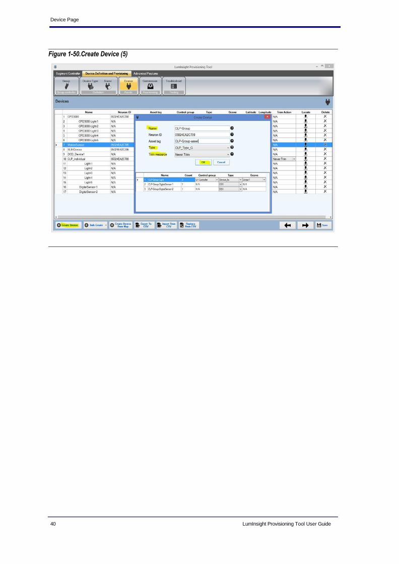
Create Device
To add single device, follow the steps below.
1. Click on the Create Device button.
2. Enter name of device,. This field is mandatory and cannot be left
empty. Device name must be unique.
3. Enter the Neuron ID. This field is mandatory and cannot be left empty. Neuron ID is 12 hexadecimal characters (0 to 9 digits and a to f alphabets).
4. Enter the asset tag.
5. Select the Group controller from the dropdown list.
6. Select the Type from the dropdown list.
If you have selected Motion Sensor definition, it will not display the group
controller and scene definition. See Figure 1-45.
If you have selected Segment Control Contractor definition, it will not display the
Neuron ID, group controller and scene definition.
36 LumInsight Provisioning Tool User Guide

LumInsight Provisioning Tool Graphical User Interface
If you have selected CPD 3000 definition then it will display the grid table in which
you have specified name for light, select group, scene and device type.
If you have selected CLP 3000 definition then it will display the grid table in which
you have specified name for light, digital sensor, select group and scene for light
and device type .
Figure 1-45.Create Device Page
7. Select the Scene definition from the dropdown list.
8. Select Trim resource from the dropdown list.
If you have selected CLP 3000 then select the Trim resource from the dropdown list.
LumInsight Provisioning Tool User Guide 37

Device Page
Figure 1-46.Create Device (1) Page
Figure 1-47.Create Device (2) Page
38 LumInsight Provisioning Tool User Guide

LumInsight Provisioning Tool Graphical User Interface
Figure 1-48.Create Device (3) Page
Figure 1-49.Create Device (4)
LumInsight Provisioning Tool User Guide 39
Device Page
Figure 1-50.Create Device (5)
40 LumInsight Provisioning Tool User Guide

LumInsight Provisioning Tool Graphical User Interface
Create Bulk Device
Follow the steps to create the Bulk of Device.
1. Enter Name for device. Name should contain alphanumeric and -_
characters. ex. La_01/LA01/La-01_001
2. Enter starting device Prefix number.
3. Enter number of device.
4. Select the Group Controller from the dropdown list.
5. Select the Type from the dropdown list.
6. Select the Scene Definition from the dropdown list
Figure 1-51.Create Bulk Device Page
Click on to create Bulk Create and
Bulk Clone as shown in Figure1-52.
1. Enter Name for device. Name should be contains alphanumeric and - _
characters. ex. La_01/LA01/La-01_001
2. Enter starting device Prefix number.
3. Enter number of device.
4. Select the Type from the dropdown list.
5. Select the Reference Device from the dropdown list.
LumInsight Provisioning Tool User Guide 41

Device Page
Figure 1-52.Bulk Clone
Create Device from Map
Follow the steps to create the Device from Map.
1. Click on device from map button, it will opens the map page as
shown in Figure1-53.
Figure 1-53.Create Device from Map
42 LumInsight Provisioning Tool User Guide

LumInsight Provisioning Tool Graphical User Interface
2. Right click on map, it will open context menu. There are three options for creating device using map.
• Device drop
• Bulk drop
• Bulk clone
Device Drop
1. Click on device drop context menu, it will open create device dialog box.
SeeFigure1-54.
2. Enter name of device, this field is mandatory and cannot be left Empty. Device name must be unique.
3. Enter the Neuron ID. This field is mandatory and cannot be left empty. Neuron ID is 12 hexadecimal characters (0 to 9 digits and a to f alphabets).
If you have selected Motion Sensor definition, It will not display the group
controller and scene definition. See Figure 1-45.
4. Select the Group controller from the dropdown list.
5. Select the Type from the dropdown list.
If you have selected Motion Sensor definition, It will not display the group
controller and scene definition.
6. Select the Scene definition from the dropdown list.
Figure 1-54. Create Device
7. Click on OK. It will display message on map left corner regarding to put device on map as shown in Figure 1-55.
LumInsight Provisioning Tool User Guide 43

Device Page
Figure 1-55.Create Device Map Page
To add the device, double click on map. Once you have located the device on map you
can change the device position using the drag and drop the device.
Figure 1-56.View of Located Device
44 LumInsight Provisioning Tool User Guide

LumInsight Provisioning Tool Graphical User Interface
Figure 1-57.Added Device
Bulk Drop
Click on Bulk drop context menu, it will open Bulk create dialog box as shown in
Figure 1-58.
1. Enter Name for device. Name should be contains alphanumeric and - _
characters. ex. La_01/LA01/La-01_001
2. Enter starting device Prefix number.
3. Enter number of device.
4. Select the Group Controller from the dropdown list.
5. Select the Device Definition from the dropdown list.
6. Select the Scene Definition from the dropdown list.
Figure 1-58. Create Bulk Device
7. Click on OK. It will display message on map left corner regarding to put
bulk device on map as shown in Figure 1-55.
LumInsight Provisioning Tool User Guide 45

Device Page
Figure 1-59.Create Bulk Device Map Page
To add the device, double click on the map. Once you have located the device on map
you can change the device position using the drag and drop the device.
Figure 1-60.View of Located Bulk Devices
46 LumInsight Provisioning Tool User Guide
LumInsight Provisioning Tool Graphical User Interface
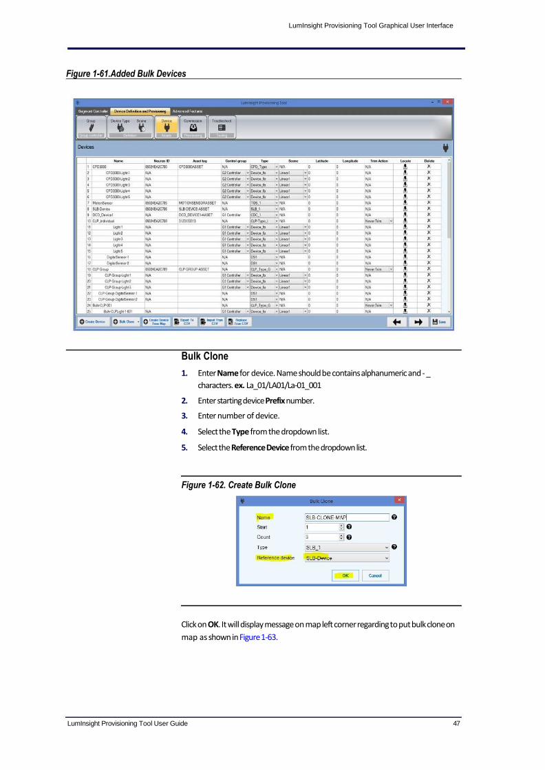
Figure 1-61.Added Bulk Devices
Bulk Clone
1. Enter Name for device. Name should be contains alphanumeric and - _
characters. ex. La_01/LA01/La-01_001
2. Enter starting device Prefix number.
3. Enter number of device.
4. Select the Type from the dropdown list.
5. Select the Reference Device from the dropdown list.
Figure 1-62. Create Bulk Clone
Click on OK. It will display message on map left corner regarding to put bulk clone on
map as shown in Figure 1-63.
LumInsight Provisioning Tool User Guide 47

Device Page
Figure 1-63.Create Device From Map
To add the Bulk clone, double click on map. Once you have located the device on map you can change the device position by dragging and dropping the device.
Figure 1-64.View of Located Bulk Clone
48 LumInsight Provisioning Tool User Guide

LumInsight Provisioning Tool Graphical User Interface
Figure 1-65.Added Bulk Clone
List of Devices
Figure 1-66.List of Devices
This page displays the list of added devices as shown in Figure 1-66.
LumInsight Provisioning Tool User Guide 49

Device Page
Delete Device
Click on icon, it will appear confirmation dialog box. Click on OK to delete
device.
You will be able to delete the multiple devices by selecting devices from the
Device page and right click on the Device page. It will display the delete
context menu. Clicking on delete context menu. You will have the
confirmation dialog box. Click on OK.
Edit Location of Device
You will able to edit the location of the device, by clicking on as
in Figure 1-67.
Figure 1-67.Edit Location of Device
Export To CSV
Click on Export Device button, to export device as shown in Figure 1-68.
50 LumInsight Provisioning Tool User Guide

LumInsight Provisioning Tool Graphical User Interface
Figure 1-68.Export To CSV
Import From CSV
You can add list of devices from a CSV file, click on "Import from CSV" button
on page of list of Devices. Adding list of devices from CSV file delete the
existing list of devices displayed in the table in the "List of Devices" page. See Figure1-
69. The CSV file must contain the following columns.
Name, Neuron ID, Asset Tag, Control Group, Type, Scene, Latitude, Longitude,
Parent Name, Trim Action (Separator between each field must be a
"Comma")
LumInsight Provisioning Tool User Guide 51

Device Page
Figure 1-69.Import From CSV
Replace From CSV
You can replace devices, by clicking on Replace from CSV button. It will
update all the devices whose Neuron ID match with file's device neuron id. And if file
device neuron id not existing, it will add new devices. After updating, click on Save
button. See Figure 1-70.
52 LumInsight Provisioning Tool User Guide

LumInsight Provisioning Tool Graphical User Interface
Figure 1-70.Replace From CSV
LumInsight Provisioning Tool User Guide 53
Commission Page
Commission
Page
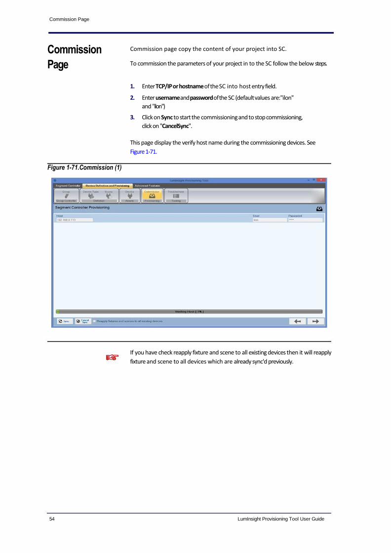
Commission page copy the content of your project into SC.
To commission the parameters of your project in to the SC follow the below steps.
1. Enter TCP/IP or hostname of the SC into host entry field.
2. Enter username and password of the SC (default values are:"ilon"
and "ilon")
3. Click on Sync to start the commissioning and to stop commissioning,
click on "CancelSync".
This page display the verify host name during the commissioning devices. See
Figure 1-71.
Figure 1-71.Commission (1)
If you have check reapply fixture and scene to all existing devices then it will reapply
fixture and scene to all devices which are already sync'd previously.
54 LumInsight Provisioning Tool User Guide

LumInsight Provisioning Tool Graphical User Interface
Figure 1-72.Commission (2)
Figure 1-73.Commission (3)
This page displays the verify FPM license during commissioning devices. See Figure1-
74.
LumInsight Provisioning Tool User Guide 55

Commission Page
Figure 1-74.Commission (4)
Figure 1-75. shows the details for upgrading the firmware version.
Figure 1-75.Commission (5)
This page displays Applying Segment Controller properties
during commissioning devices. See Figure 1-76.
56 LumInsight Provisioning Tool User Guide

LumInsight Provisioning Tool Graphical User Interface
Figure 1-76.Commission (6)
This page displays the Applying devices during commissioning devices. See
Figure1- 77.
Figure 1-77.Commission (7)
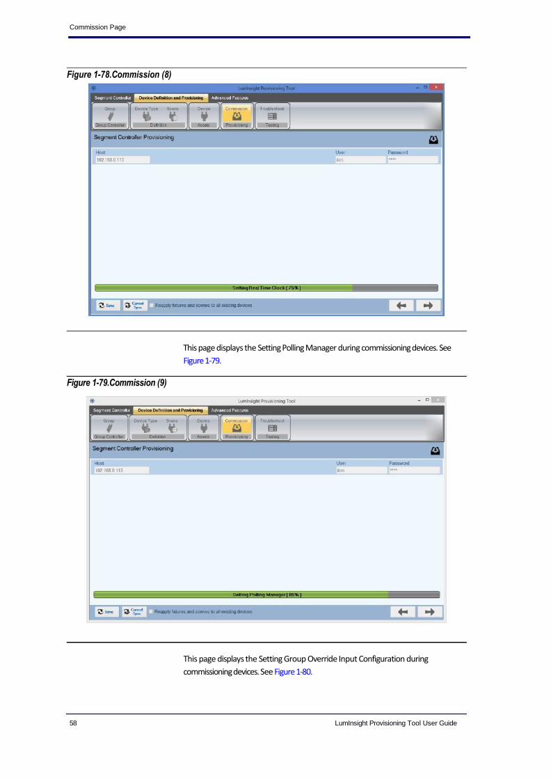
This page displays the Setting Real Time Clock during commissioning devices. See
Figure 1-78.
LumInsight Provisioning Tool User Guide 57
Commission Page
Figure 1-78.Commission (8)
Figure 1-79.Commission (9)
This page displays the Setting Polling Manager during commissioning devices. See
Figure 1-79.
This page displays the Setting Group Override Input Configuration during
commissioning devices. See Figure 1-80.
58 LumInsight Provisioning Tool User Guide

LumInsight Provisioning Tool Graphical User Interface
Figure 1-80.Commission (10)
This page displays the Verifying Configuration during commissioning devices.
See Figure1-81.
Figure 1-81.Commission (11)
This page display the operations performed on the devices like.
1. Devices are removed from the Segment Controller.
LumInsight Provisioning Tool User Guide 59

Commission Page
2. Devices are added into the Segment Controller.
3. Neuron ID for devices are updated into the Segment Controller.
4. Devices are removed from the ERDP file.
5. Neuron ID for device are replaced into the ERDP file.
ERDP file is backup before removing the devices from the ERDP file. ERDP files at
the same path.
Figure 1-82.Commission (12)
This page displays the reboot and Shut Down segment controller for put
smartserver in proper state. If you have pressed Yes, it will reboot smart
server. It will take few minutes for reboot smartserver. If you have pressed No, it
will complete your sync process. See Figure 1-83.
60 LumInsight Provisioning Tool User Guide

LumInsight Provisioning Tool Graphical User Interface
Figure 1-83.Commission (13)
This page display the commissioning devices is successfully commission. See Figure1-84.
Figure 1-84.Commission (14)
LumInsight Provisioning Tool User Guide 61

Troubleshoot
Figure 1-85.Commission (15)
Troubleshoot The troubleshoot page enables you to test each OLC connected to SC and check:
It can be switched ON, OFF, DIM.
It takes correct feedback from SC.
User can easily select all devices using Select All button or unselect all device using
Unselect All button.
62 LumInsight Provisioning Tool User Guide

LumInsight Provisioning Tool Graphical User Interface
Figure 1-86.Selected All Device
Figure 1-87.Unselected All Device (1)
For Toggle Devices: Shift +click on check box, it will toggle all devices from first
to up to clicked device.
LumInsight Provisioning Tool User Guide 63
Troubleshoot
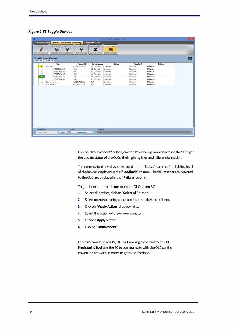
Figure 1-88.Toggle Devices
Click on "Troubleshoot" button, and the Provisioning Tool connects to the SC to get
the update status of the OLCs, their lighting level and failure information.
The commissioning status is displayed in the "Status" column. The lighting level
of the lamp is displayed in the "Feedback" column. The failures that are detected
by the OLC are displayed in the "Failure" column.
To get Information of one or more OLCs from SC.
1. Select all devices, click on "Select All" button.
2. Select one device using check box located in behind of them.
3. Click on "Apply Action" dropdown list.
4. Select the action whatever you want to.
5. Click on Apply button.
6. Click on "Troubleshoot".
Each time you send an ON, OFF or Dimming command to an OLC,
Provisioning Tool asks the SC to communicate with the OLC on the
PowerLine network, in order to get fresh feedback.
64 LumInsight Provisioning Tool User Guide
LumInsight Provisioning Tool Graphical User Interface
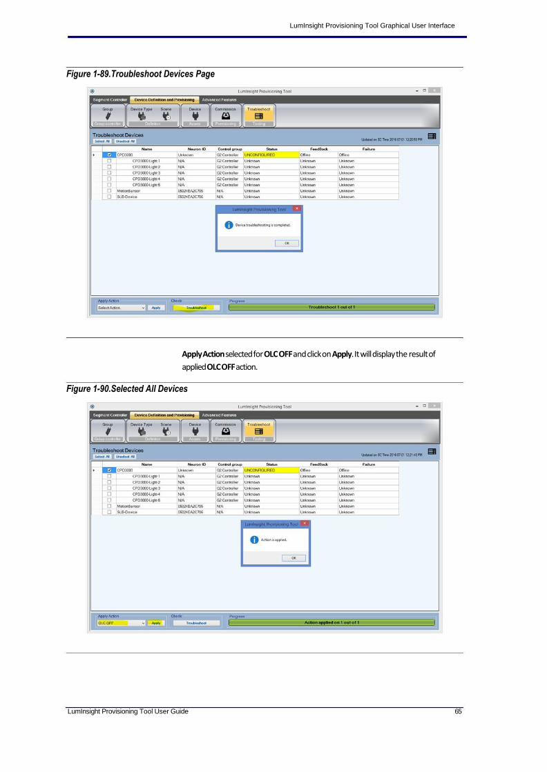
Figure 1-89.Troubleshoot Devices Page
Apply Action selected for OLC OFF and click on Apply. It will display the result of
applied OLC OFF action.
Figure 1-90.Selected All Devices
LumInsight Provisioning Tool User Guide 65

Troubleshoot
Apply Action selected for Dimming and click on Apply. It will display the result of
applied Dimming action.
Figure 1-91.Troubleshoot Devices
Apply Action selected for Recommission and click on Apply. It will display the result of
applied Recommission action.
Figure 1-92.Troubleshoot Devices (1)
66 LumInsight Provisioning Tool User Guide

LumInsight Provisioning Tool Graphical User Interface
Apply Action selected for Segment Controller and click on Apply. It will display
the result of applied Reboot Segment Controller action.
Figure 1-93.Troubleshoot Devices (2)
Figure 1-94.Troubleshoot Devices (3)
LumInsight Provisioning Tool User Guide 67

Troubleshoot
For devices that successfully pass the troubleshooting check, the box next to
them will be unchecked. For devices that fail to pass the troubleshooting
check, a check will appear in the box.
68 LumInsight Provisioning Tool User Guide

LumInsight Provisioning Tool Graphical User Interface
Advanced
Features
Figure 1-95.Control Data
Polling Manager
This page has two options available, Control data and Fault data.
Control Data
• Select the Poll Delay from the dropdown.
• Select the Scan Interval from the dropdown. The is the time interval
to scan the nvoLc Control Data Operation data.
• Enter the Start Delay. Seconds to delay calculation.
• Disabling the polling will persist until you take action to re-enable it
again. This will turn off historical data access.
• Enter the Lost Device Threshold. The number of confirmed
lost Devices raises system comms alarm.
• Enter the Response Fail Threshold. When a poll of a data point on a
device fails at least this number of consecutive times, a lost device alarm is triggered.
Fault Data
• Select the Poll Delay from the dropdown.
• Select the Scan Interval from the dropdown. The interval is the
time to scan the nvoLc Status fault data.
• Enter the Start Delay. Time is second to delay calculation if the first
scan time to allowed data server to complete object initialization.
• Disabling the polling will persist until you take action to enable
again. This will turn off historical data access.
LumInsight Provisioning Tool User Guide 69

Advanced Features
Figure 1-96.Fault Data
• Enter the Lost Device Threshold. The number of confirmed lost Devices necessary for system comm alarm
• Enter the Response Fail Threshold. When a poll of a data point on a
device fails at least this number of consecutive times, a lost device alarm is triggered.
70 LumInsight Provisioning Tool User Guide

LumInsight Provisioning Tool Graphical User Interface
About Page
Figure 1-97.About Page
Click on About LumInsight Provisioning Tool, it will show the system
information about the application version as shown in Figure 1-98.
Figure 1-98.System Information
LumInsight Provisioning Tool User Guide 71

Exit
Exit
Figure 1-99.Exit
To exit your system, click on top most left corner button. Then click on the
Close option as shown in Figure 1-99. When you try to exit system and your
project is opened, it will ask to save the project.
72 LumInsight Provisioning Tool User Guide