Embed Size (px)
Citation preview
IRLP Embedded Node Information Page 1 of 23 Rev 1d – Mar 22, 2012
This document outlines some details to help you better understand the features of your new IRLP embedded node. It also contains a couple of "gotchas" and FAQ type information pieces. As more questions are asked, more information will be added to this document. An embedded node is an IRLP node that is optimized for speed, low power consumption, and reliability. Many of the scripts written for IRLP nodes will work on your embedded node. Most of the information you will require is available from the following website: http://www.irlp.net/new-install/ This document will live online as a PDF file. The version of the PDF will be updated as more things are added to the document. Please refer to the ChangeLog on the last page of this document for details on the updates. David Cameron – VE7LTD IRLP System Designer
IRLP Embedded Node Information Page 2 of 23 Rev 1d – Mar 22, 2012
Table of Contents Technical Details ................................................................................................... 3
Wiring .................................................................................................................... 3
IRLP Board Jumper Adjustments .......................................................................... 5
IRLP Board Function Tests ................................................................................... 6
Flash Disk File System ......................................................................................... 7
The First Login and the ROOT Password ............................................................. 7
Editing Configuration Files with nano or pico ........................................................ 8
Synchronization of the Flash Drive ....................................................................... 9
Configuring the Network Adapter ........................................................................ 10
Forwarding IRLP Ports through a Router ............................................................ 11
Timezone Configuration and Time Setting .......................................................... 12
The IRLP Troubleshooting Script ........................................................................ 13
The /home/irlp/custom/update-file-list File ........................................................ 13
Remote Access Using Secure Shell (SSH) ......................................................... 14
Adjusting Audio Levels ........................................................................................ 15
The audio_level_test Script ................................................................................. 16
Mixing Audio Channels ....................................................................................... 16
Installed Features ............................................................................................... 17
REMOTE WEB ADMIN ................................................................................... 17
MORSE_ID...................................................................................................... 18
CONTROLLER ................................................................................................ 19
SPEAKTIME .................................................................................................... 20
STAR69 ........................................................................................................... 20
EchoIRLP ........................................................................................................ 20
IRLP_VPN ....................................................................................................... 21
Next Steps .......................................................................................................... 22
Change Log ........................................................................................................ 23
IRLP Embedded Node Information Page 3 of 23 Rev 1d – Mar 22, 2012
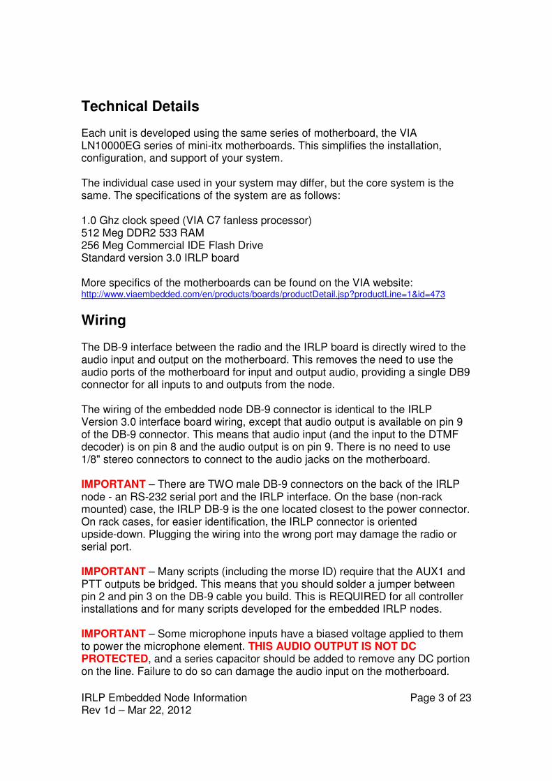
Technical Details Each unit is developed using the same series of motherboard, the VIA LN10000EG series of mini-itx motherboards. This simplifies the installation, configuration, and support of your system. The individual case used in your system may differ, but the core system is the same. The specifications of the system are as follows: 1.0 Ghz clock speed (VIA C7 fanless processor) 512 Meg DDR2 533 RAM 256 Meg Commercial IDE Flash Drive Standard version 3.0 IRLP board More specifics of the motherboards can be found on the VIA website: http://www.viaembedded.com/en/products/boards/productDetail.jsp?productLine=1&id=473
Wiring The DB-9 interface between the radio and the IRLP board is directly wired to the audio input and output on the motherboard. This removes the need to use the audio ports of the motherboard for input and output audio, providing a single DB9 connector for all inputs to and outputs from the node. The wiring of the embedded node DB-9 connector is identical to the IRLP Version 3.0 interface board wiring, except that audio output is available on pin 9 of the DB-9 connector. This means that audio input (and the input to the DTMF decoder) is on pin 8 and the audio output is on pin 9. There is no need to use 1/8" stereo connectors to connect to the audio jacks on the motherboard. IMPORTANT – There are TWO male DB-9 connectors on the back of the IRLP node - an RS-232 serial port and the IRLP interface. On the base (non-rack mounted) case, the IRLP DB-9 is the one located closest to the power connector. On rack cases, for easier identification, the IRLP connector is oriented upside-down. Plugging the wiring into the wrong port may damage the radio or serial port. IMPORTANT – Many scripts (including the morse ID) require that the AUX1 and PTT outputs be bridged. This means that you should solder a jumper between pin 2 and pin 3 on the DB-9 cable you build. This is REQUIRED for all controller installations and for many scripts developed for the embedded IRLP nodes. IMPORTANT – Some microphone inputs have a biased voltage applied to them to power the microphone element. THIS AUDIO OUTPUT IS NOT DC PROTECTED, and a series capacitor should be added to remove any DC portion on the line. Failure to do so can damage the audio input on the motherboard.
IRLP Embedded Node InformationRev 1d – Mar 22, 2012
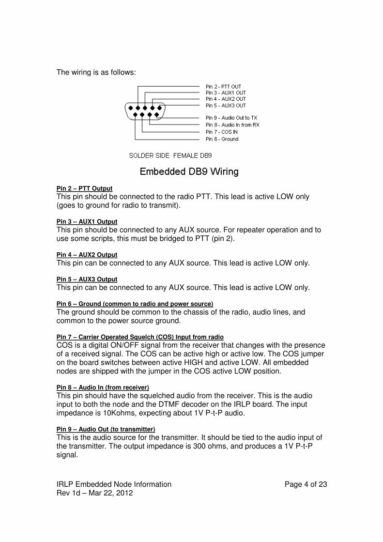
The wiring is as follows:
Pin 2 – PTT Output
This pin should be connected to the radio PTT. This lead is active LOW only (goes to ground for radio to transmit). Pin 3 – AUX1 Output
This pin should be connected to any AUX source. For repeateuse some scripts, this must be Pin 4 – AUX2 Output
This pin can be connected to any AUX source. This lead is active LOW Pin 5 – AUX3 Output
This pin can be connected to any AUX source. This lead is active LOW Pin 6 – Ground (common to radio and power source)
The ground should be common to the chassis of the radio, common to the power source Pin 7 – Carrier Operated Squelch
COS is a digital ON/OFF signal from the reof a received signal. The COS can be active high or active low. The COS jumper on the board switches between active nodes are shipped with the jumper in the COS active LOW position. Pin 8 – Audio In (from receiver)
This pin should have the input to both the node and the DTMF decoder on the impedance is 10Kohms, expecting about 1V P Pin 9 – Audio Out (to transmitter)
This is the audio source for the transmitter. It should be tied to the the transmitter. The output impedance is 300 ohms, and produces a 1V Psignal.
Node Information
The wiring is as follows:
This pin should be connected to the radio PTT. This lead is active LOW only (goes to ground for radio to transmit).
This pin should be connected to any AUX source. For repeater operation and to use some scripts, this must be bridged to PTT (pin 2).
This pin can be connected to any AUX source. This lead is active LOW
This pin can be connected to any AUX source. This lead is active LOW
Ground (common to radio and power source)
The ground should be common to the chassis of the radio, audio lines, common to the power source ground.
Carrier Operated Squelch (COS) Input from radio
COS is a digital ON/OFF signal from the receiver that changes with the presence The COS can be active high or active low. The COS jumper
on the board switches between active HIGH and active LOW. All nodes are shipped with the jumper in the COS active LOW position.
Audio In (from receiver)
This pin should have the squelched audio from the receiver. This is the audio input to both the node and the DTMF decoder on the IRLP board.impedance is 10Kohms, expecting about 1V P-t-P audio.
(to transmitter)
is the audio source for the transmitter. It should be tied to the The output impedance is 300 ohms, and produces a 1V P
Page 4 of 23
This pin should be connected to the radio PTT. This lead is active LOW only
r operation and to
This pin can be connected to any AUX source. This lead is active LOW only.
This pin can be connected to any AUX source. This lead is active LOW only.
audio lines, and
ceiver that changes with the presence The COS can be active high or active low. The COS jumper
. All embedded nodes are shipped with the jumper in the COS active LOW position.
rom the receiver. This is the audio board. The input
is the audio source for the transmitter. It should be tied to the audio input of The output impedance is 300 ohms, and produces a 1V P-t-P
IRLP Embedded Node Information Page 5 of 23 Rev 1d – Mar 22, 2012
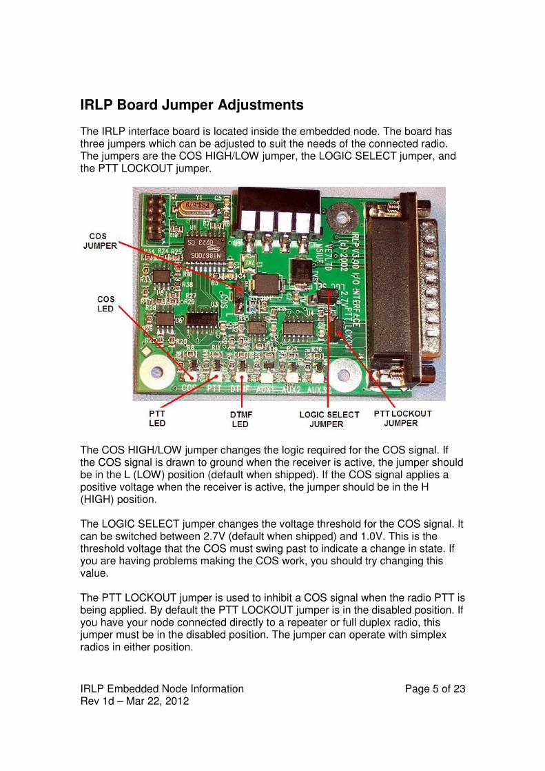
IRLP Board Jumper Adjustments The IRLP interface board is located inside the embedded node. The board has three jumpers which can be adjusted to suit the needs of the connected radio. The jumpers are the COS HIGH/LOW jumper, the LOGIC SELECT jumper, and the PTT LOCKOUT jumper.
The COS HIGH/LOW jumper changes the logic required for the COS signal. If the COS signal is drawn to ground when the receiver is active, the jumper should be in the L (LOW) position (default when shipped). If the COS signal applies a positive voltage when the receiver is active, the jumper should be in the H (HIGH) position. The LOGIC SELECT jumper changes the voltage threshold for the COS signal. It can be switched between 2.7V (default when shipped) and 1.0V. This is the threshold voltage that the COS must swing past to indicate a change in state. If you are having problems making the COS work, you should try changing this value. The PTT LOCKOUT jumper is used to inhibit a COS signal when the radio PTT is being applied. By default the PTT LOCKOUT jumper is in the disabled position. If you have your node connected directly to a repeater or full duplex radio, this jumper must be in the disabled position. The jumper can operate with simplex radios in either position.
IRLP Embedded Node Information Page 6 of 23 Rev 1d – Mar 22, 2012
IRLP Board Function Tests Once the wiring is complete, and the jumpers are set in the correct position, you should perform a few tests. This is best done with the IRLP interface board in view, but can also be performed on the computer console. To monitor on the console, use the program: readinput
To exit the readinput program, press CTRL+C.
1) COS Function Test Transmit a signal into the radio connected to the node. The green COS LED should illuminate with a signal, and turn off with no signal. If monitoring on the console, the words “COS ACTIVE” should show on the screen with a signal and “COS INACTIVE” without. If the signals are opposite, change the position of the COS HIGH/LOW jumper. If no change is observed, check your wiring to pin 7 of the IRLP DB-9, and ensure the radio and node share a common ground.
2) DTMF Function Test Transmit a signal with some DTMF tones. The green COS LED should illuminate with the signal, and the yellow DTMF LED should illuminate with each DTMF tone. If monitoring on the console, the words “COS ACTIVE” should show on the screen followed by DTMF X for each tone pressed, followed by “COS INACTIVE”. If this is not observed, check your wiring to pin 8 of the IRLP DB-9, and ensure the radio and node share a common ground.
3) PTT Function Test Note: If you are running the readinput program, press CTRL+C to exit. Using the computer console, type the commands: key
unkey
The radio should key and unkey, and the red PTT LED should illuminate and go out. If this is not observed, check your wiring to pin 2 of the IRLP DB-9, and ensure the radio and node share a common ground.
IRLP Embedded Node Information Page 7 of 23 Rev 1d – Mar 22, 2012
Flash Disk File System The flash disk is a 256 megabyte solid state disk, which operates as a standard IDE device. It is partitioned in two partitions: a 2 megabyte FAT12 partition (used for booting using syslinux) and a 254 megabyte ext2 partition (used for the Linux and IRLP file system). Neither file system is compressed, as 256 megabytes is plenty of space. There is approximately 35 megabytes used by default for the Linux file system and the IRLP files. This leaves about 200 usable megabytes free for log files and customization. This also leaves 250 megabytes of RAM free for use by Linux. 16 megabytes of the RAM is used by the VGA display controller. The entire system loads from the ext2 partition into RAM on boot, and then continues to run from RAM, so that there can be no damage to the flash device from repeated write/re-write cycles. The flash device is designed for several million read and write cycles, but in the design of the system, the flash device will outlive the life of the node. This system should also never require a reboot.
The First Login and the ROOT Password For the first login, you will require a VGA monitor and PS2 style keyboard. Once the embedded computer has finished booting, you will be presented with a login prompt. The user you will log into your embedded node with is: root
The default root password on every shipped embedded IRLP node is: rootirlp
The system will force you to change this on first login. DO NOT forget your password, as we cannot recover it for you. Your whole system will have to be re-flashed and reconfigured from scratch. This is because it is very difficult to modify files (including the password file) on the flash drive, as it is only used read-only. Once the initial passwords are set, the changes are automatically synced to the flash device for the next boot. The repeater user password and IRLP Web Admin user (username=remote) passwords are also set on the first boot. NOTE: All usernames, password, filenames, commands are CASE SENSITIVE. Be sure to look carefully at the directions when executing setting passwords and issuing commands.
IRLP Embedded Node Information Page 8 of 23 Rev 1d – Mar 22, 2012
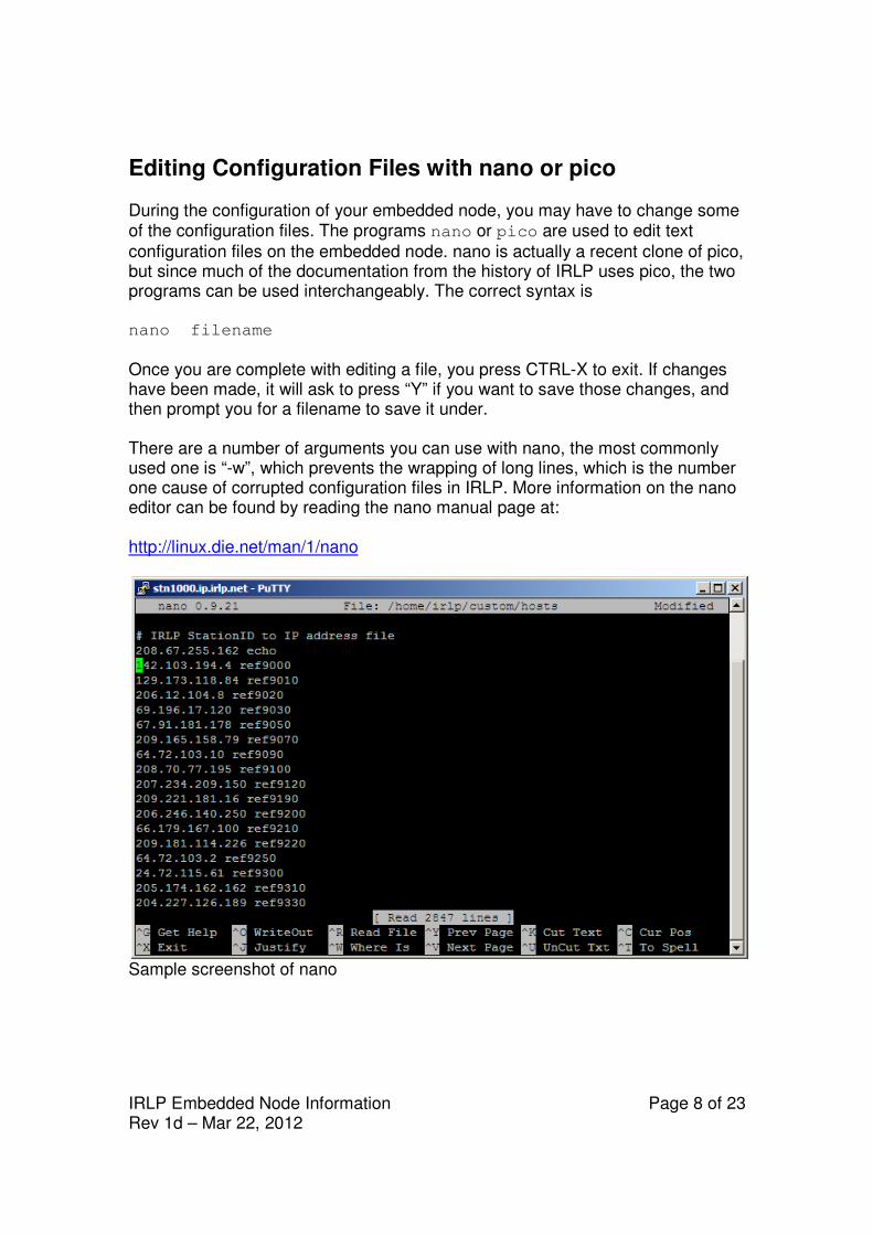
Editing Configuration Files with nano or pico During the configuration of your embedded node, you may have to change some of the configuration files. The programs nano or pico are used to edit text
configuration files on the embedded node. nano is actually a recent clone of pico, but since much of the documentation from the history of IRLP uses pico, the two programs can be used interchangeably. The correct syntax is nano filename
Once you are complete with editing a file, you press CTRL-X to exit. If changes have been made, it will ask to press “Y” if you want to save those changes, and then prompt you for a filename to save it under. There are a number of arguments you can use with nano, the most commonly used one is “-w”, which prevents the wrapping of long lines, which is the number one cause of corrupted configuration files in IRLP. More information on the nano editor can be found by reading the nano manual page at: http://linux.die.net/man/1/nano
Sample screenshot of nano
IRLP Embedded Node Information Page 9 of 23 Rev 1d – Mar 22, 2012
Synchronization of the Flash Drive The script: flash_sync
synchronizes the current file system operating in RAM with the flash drive. This backs up all log files, configurations, settings etc. Since your file system is volatile, you must remember to run the flash_sync script after any changes to make sure the flash drive is current before a reboot. Be careful NOT to write large files to the flash device. If the flash device is full, the file system may not load on boot, and your node may have to be re-flashed from scratch, losing its entire configuration. You can control which files are NOT updated by editing and adding the files to the following file: /etc/flash_sync_exclude
DO NOT remove any of the entries that are currently pre-configured in the file. If you do, you run the risk of crashing the flash drive, requiring a full re-flash. The flash_sync script is run daily from the following script: /etc/cron.daily/flash_sync_quiet
The script must be run as root, so if you plan to keep your flash drive more up to date than once per day, you should set the quiet script to run more often.
IRLP Embedded Node Information Page 10 of 23 Rev 1d – Mar 22, 2012
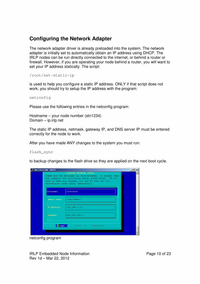
Configuring the Network Adapter The network adapter driver is already preloaded into the system. The network adapter is initially set to automatically obtain an IP address using DHCP. The IRLP nodes can be run directly connected to the internet, or behind a router or firewall. However, if you are operating your node behind a router, you will want to set your IP address statically. The script: /root/set-static-ip
is used to help you configure a static IP address. ONLY if that script does not work, you should try to setup the IP address with the program: netconfig
Please use the following entries in the netconfig program: Hostname – your node number (stn1234) Domain – ip.irlp.net The static IP address, netmask, gateway IP, and DNS server IP must be entered correctly for the node to work. After you have made ANY changes to the system you must run: flash_sync
to backup changes to the flash drive so they are applied on the next boot cycle.
netconfig program
IRLP Embedded Node Information Page 11 of 23 Rev 1d – Mar 22, 2012
Forwarding IRLP Ports through a Router As with any other IRLP node, if your embedded node is behind a router, you have to forward some TCP and UDP ports to the node, or put the node into the DMZ of the router. The IP address of your node should have automatically been set static by the scripts in the section "Configuring the Network Adapter". You will need to forward the following ports through your router to the IRLP node: 15425 TCP 2074 to 2093 UDP
If you want to be able to access the remote web administrator from the outside, you will also need to forward: 80 TCP
If you are using Echolink (EchoIRLP) on the embedded node, you will also need to forward: 5198 and 5199 UDP
If you want to access your console remotely (through SSH), or would like help from the support crew remotely, you will have to forward: 15426 TCP
Alternately, if your router has a "DMZ" feature, you can put the IP address of the node into the DMZ, and all ports will be forwarded to the IRLP node. More information of ways to perform the port forwarding or DMZ setting is available in the “IRLP behind a Router or Firewall” section at: http://www.irlp.net/new-install/
IRLP Embedded Node Information Page 12 of 23 Rev 1d – Mar 22, 2012
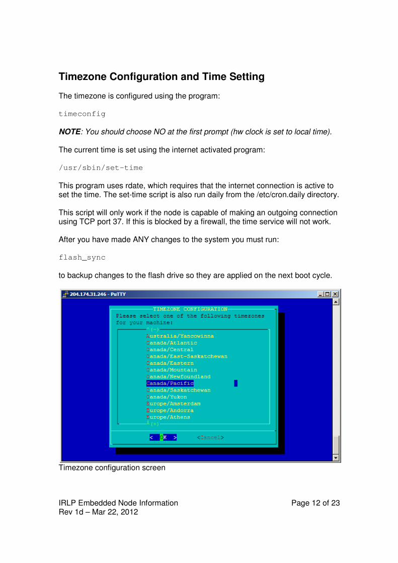
Timezone Configuration and Time Setting The timezone is configured using the program: timeconfig
NOTE: You should choose NO at the first prompt (hw clock is set to local time). The current time is set using the internet activated program: /usr/sbin/set-time
This program uses rdate, which requires that the internet connection is active to set the time. The set-time script is also run daily from the /etc/cron.daily directory. This script will only work if the node is capable of making an outgoing connection using TCP port 37. If this is blocked by a firewall, the time service will not work. After you have made ANY changes to the system you must run: flash_sync
to backup changes to the flash drive so they are applied on the next boot cycle.
Timezone configuration screen
IRLP Embedded Node Information Page 13 of 23 Rev 1d – Mar 22, 2012
The IRLP Troubleshooting Script The software on the embedded node contains a script that will help you determine if there are any problems with your node. The script tests a number of conditions, and is used as the basis of diagnosis by the IRLP support team. To run the troubleshooting script, log in and type: su – repeater (su SPACE MINUS SPACE repeater)
troubleshoot-irlp
Details on each step of the script and possible causes and solutions can be found on the following webpage: http://www.irlp.net/ts.html IMPORTANT – As your embedded node contains entries to allow EchoIRLP to work, it will fail Test 10 – Environment File Corruption Test. THIS CAN SAFELY BE IGNORED.
The /home/irlp/custom/update-file-list File The file: /home/irlp/custom/update-file-list
contains some important entries to prevent certain files special to your node from being overwritten during IRLP updates. In order to prevent duplication, the wget, rsync, and nc (netcat) files are not pulled from the IRLP server. Instead, the locally installed versions (which are newer) are retained and linked to the irlp file tree. If you wish to edit any of the files or scripts under the /home/irlp/ directory, and do not want them to be overwritten, just add entries into this file. This is a feature common to all IRLP nodes.
IRLP Embedded Node Information Page 14 of 23 Rev 1d – Mar 22, 2012
Remote Access Using Secure Shell (SSH) SSH is a secure and encrypted protocol used to remotely communicate with your embedded node. If you are using Windows as your primary computer, you should download and install puTTY and WinSCP as two tools to assist you with controlling your node. The SSH port defaults to TCP 15426. This is made to prevent standard hacking scripts that hunt SSH servers have a harder time finding your node. This means you have to program port 15426 into any SSH or SCP program (such as PuTTY or WinSCP) you may use. Also, if you wish to have remote access to your IRLP node, you will need to forward port 15426/TCP as well. In winSCP and puTTY you can set the port to 15426 where you set the IP. In linux, you can use the format ssh –p15426 IP_address. If you wish to change the SSH port to another port, you can edit the Port option in the /etc/ssh/sshd_config file. NOTE: On the embedded nodes, I am experimenting with installing a "public key" on your node which will allow me to login to the nodes with root access without a password. You can remove this feature by removing the file: rm /root/.ssh/authorized_keys2
After you have made ANY changes to the system you must run: flash_sync
to backup changes to the flash drive so they are applied on the next boot cycle.
IRLP Embedded Node Information Page 15 of 23 Rev 1d – Mar 22, 2012
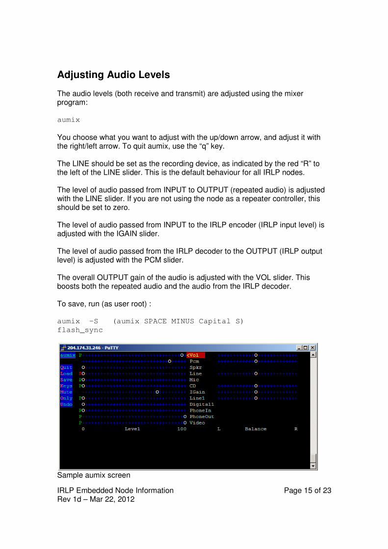
Adjusting Audio Levels The audio levels (both receive and transmit) are adjusted using the mixer program: aumix
You choose what you want to adjust with the up/down arrow, and adjust it with the right/left arrow. To quit aumix, use the “q” key. The LINE should be set as the recording device, as indicated by the red “R” to the left of the LINE slider. This is the default behaviour for all IRLP nodes. The level of audio passed from INPUT to OUTPUT (repeated audio) is adjusted with the LINE slider. If you are not using the node as a repeater controller, this should be set to zero. The level of audio passed from INPUT to the IRLP encoder (IRLP input level) is adjusted with the IGAIN slider. The level of audio passed from the IRLP decoder to the OUTPUT (IRLP output level) is adjusted with the PCM slider. The overall OUTPUT gain of the audio is adjusted with the VOL slider. This boosts both the repeated audio and the audio from the IRLP decoder. To save, run (as user root) : aumix –S (aumix SPACE MINUS Capital S)
flash_sync
Sample aumix screen
IRLP Embedded Node Information Page 16 of 23 Rev 1d – Mar 22, 2012
The audio_level_test Script A special script has been designed to assist with the initial setting of audio levels. The script can be invoked using the “repeater” user from the console with the following commands: su - repeater (su SPACE MINUS SPACE repeater)
audio_level_test
The script will key up and prompt you "Audio level test ready". You must now send at least 8 seconds of audio, either voice audio or continuous tone audio. If using DTMF, use the "D" key. Once you unkey, it will process the audio file and report back: "Audio Level 6 6 percent" (median level is 66 out of 100 - GOOD) "Clipping 0 percent" (percentage of clipped samples is 0 - GOOD) You want to adjust the audio so it is right on the brink of clipping with voice audio. You would then adjust the IGAIN slider in the aumix program to raise or lower the input level. An audio level between 70-80 with 0 clipping on a continuous DTMF tone "D" is good. On a voice signal, an audio level greater than 50, with a clipping less than 5% is good. The numbers will vary between voices and tones, but as long as the clipping is not too high, and the level is not too low, you will be sending good audio.
Mixing Audio Channels One of the best and most useful features of the driver/chipset combination of the ALSA/VIA audio chipset is the ability to easily mix audio signals into the output device. Up to six simultaneous signals can be mixed, just by playing them using their normal means. This is not true of all other IRLP systems. For example, you can play IRLP audio, an MP3, a courtesy tone, a morse ID, and a voice ID… All at once! All of these use the same DSP device at the same time.
IRLP Embedded Node Information Page 17 of 23 Rev 1d – Mar 22, 2012
Installed Features The embedded nodes are pre-loaded with a series of commonly used add-on features. These feature can be enabled or disabled by adjusting flags in the file: /home/irlp/features/features.env After you have made ANY changes to the system you must run: flash_sync
to backup changes to the flash drive so they are applied on the next boot cycle.
REMOTE WEB ADMIN
The IRLP Remote Web Admin is installed by default on all embedded IRLP nodes. This allows you to perform some simple control features from any web enabled computer. You can send DTMF to the decode script, enable/disable the node, drop the current connection, edit several files, view the messages file, and see the status of your node. You access your remote admin system by entering the URL http://stnxxxx.ip.irlp.net/control/
NOTE: You must forward port 80/TCP through your router for this to work from outside your network. Some ISPs will block incoming data on port 80. The default username and password are: remote/remote. These will be changed on first login. If you lose the remote user password for the remote web administrator, it can be reset by entering the following command as the root user: htpasswd /etc/htpasswd remote
IRLP Embedded Node Information Page 18 of 23 Rev 1d – Mar 22, 2012
MORSE_ID
The morse code generator cwpcm is installed by default on all embedded nodes. There are a series of scripts that can be run using this program to generate morse code identifiers. The format for using the program is: echo $CALLSIGN | cwpcm –sf –l 10 –p 1000 > /dev/dsp (plays "callsign" at fast rate, 10% volume, 1000 Hz)
The sample script which keys, plays the morse ID, and unkeys is at: /home/irlp/features/morese_id/id_now
cwpcm arguments:
-ss for slow code rate (USA Technician?)
-sm for medium code rate
-sf for fast code rate
-sx for extra fast code rate (USA Extra?)
-l <0..100> set the output level
-p <0..3000> set the pitch
IRLP Embedded Node Information Page 19 of 23 Rev 1d – Mar 22, 2012
CONTROLLER
The IRLP controller program is a simple controller that provides hangtime, DTMF muting, activity controller ID, and programmable courtesy tones. The IRLP controller requires a pair of courtesy tone files to be setup. The controller requires files to be made that are RAW (no header), 8 bit, with a sample rate of 8000hz. The names are ct1.raw and ct2.raw. ct1.raw is played for local traffic, and ct2.raw is played for remote (IRLP and controller generated traffic). These can be made to whatever you like, using a program like CoolEdit. You can then use a program like WinSCP to transfer the files from a windows machine onto the embedded node. After the files have been sent, the flash_sync script must be run to save the changes. The controller has an environment file at: /home/irlp/features/controller/controller.env
which can adjust many of the features of the controller. You can adjust:
• The hangtime in milliseconds.
• The shortkey timer in milliseconds (COS time required for hangtime activation).
• The alligator timer in seconds (COS timeout).
• The DTMF mute on/off.
• The DTMF mute duration in milliseconds.
• The ID interval in seconds (time between IDs).
• The courtesy tone frequency. After making any changes to the environment file, the controller must be restarted by running: /home/irlp/custom/rc.irlp
The DTMF mute is accomplished by setting the LINE volume slider to zero. This is done in software. This only affects the audio being passed from the Line INPUT to the Line OUTPUT, and not the volume of your IRLP output audio.
IRLP Embedded Node Information Page 20 of 23 Rev 1d – Mar 22, 2012
SPEAKTIME
The speaktime script is already pre-installed on the system. The DTMF code “C” is used to invoke the speaktime script.
STAR69
The star69 script is already pre-installed on the system. The DTMF code “*69” is used to invoke the star69 script.
EchoIRLP
EchoIRLP allows you to run both an Echolink and an IRLP node from the same computer and radio hardware. The EchoIRLP system is installed on each embedded system, but disabled by default. You must configure your own EchoIRLP system, by editing a series of configuration files. If provided at the time of order, the node will be preconfigured with your EchoIRLP settings. The configuration files for EchoIRLP are located in: /home/irlp/features/EchoIRLP/custom/
The files you will need to customize are: userdata.txt tbd.conf echo_environment
IRLP Embedded Node Information Page 21 of 23 Rev 1d – Mar 22, 2012
IRLP_VPN
The IRLP_VPN is a system which will give you a routable IP address, even when you are located behind a router (or multiple routers) which you do not have access to. The IRLP_VPN service is offered (currently free of charge) to IRLP users who request an account. Your embedded node is preconfigured with a test account, so you can see the benefits of using the VPN. The test account may be terminated at any time. If you wish to continue using the IRLP_VPN system please contact [email protected] to be set up with a permanent account. Each IP address costs money, so heavy users may be asked to support the system. To activate the IRLP_VPN, you use the script: start_tunnel
To close the connection, you use the script: stop_tunnel
The tunnel sets up routes to/from your node and the server, and will disconnect any active connections you currently have. It also takes about a minute for your new IP address to synchronize across the IRLP network, so do not expect to receive any incoming calls right after you start the tunnel. There is also a flag to start the tunnel when the node is booted in the /home/irlp/features/features.env file.
IRLP Embedded Node Information Page 22 of 23 Rev 1d – Mar 22, 2012
Next Steps Once the router has been configured, your node passed the troubleshooting script, and the audio levels have been set, you are ready to start enjoying your new embedded node. There are few more steps you should perform in order to advertise your node, and become more informed about the IRLP network. Please review the “What to do After the Install” document at: http://www.irlp.net/new-install/afterinstallv2.pdf Using this document, you can complete the following steps:
1) Publish your node on the IRLP Status Page (http://status.irlp.net) 2) Join the IRLP and Embedded-IRLP Yahoo Groups 3) Record and upload your connect/disconnect audio files 4) Test your node for a PULSEBACK and adjust the timing file 5) Learn a few operating guidelines.
IRLP Embedded Node Information Page 23 of 23 Rev 1d – Mar 22, 2012
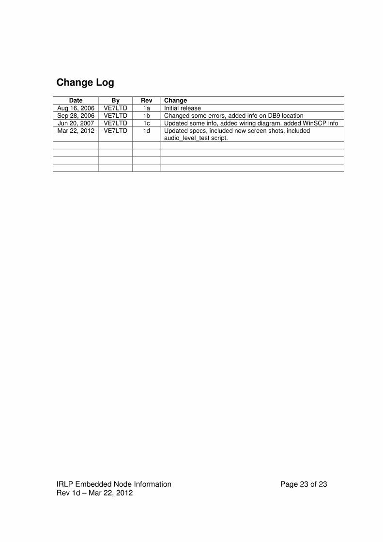
Change Log
Date By Rev Change
Aug 16, 2006 VE7LTD 1a Initial release
Sep 28, 2006 VE7LTD 1b Changed some errors, added info on DB9 location
Jun 20, 2007 VE7LTD 1c Updated some info, added wiring diagram, added WinSCP info
Mar 22, 2012 VE7LTD 1d Updated specs, included new screen shots, included audio_level_test script.