Embed Size (px)
Citation preview

ME6702 MECHATRONICS
Mr.P.SANTHOSH AP/Mech Page 1
PART – B (5 x 16 =80)
1. Explain with a help of neat diagram of Pin out details of 8085 microprocessor.
Intel 8085 consists of 40 pins and signal can be classified as follow:
Address Bus.
Data Bus.
Control and Status signals.
Power supply and frequency signals.
Externally initiated signals.
Serial I/O ports.
ADDRESS BUS
The 8085 has eight signal lines, A15 – A8 : Unidirectional, known as ‘high order
address’.
DATA BUS
AD7 – AD0: bidirectional and dual purpose (address and data placed once at a time).
AD7 – AD0 also known as ‘low order addresses’.
To execute an instruction, at early stage AD7 – AD0 uses as address bus and alternately
as data bus for the next cycle.
The method to be change from address bus to data bus known as ‘bus multiplexing’.

ME6702 MECHATRONICS
Mr.P.SANTHOSH AP/Mech Page 2
CONTROL AND STATUS SIGNAL
ALE – This signal helps to capture the lower order address presented on the multiplexed
address/data bus.
The ALE (Address Latch Enable) signal enables the lower order address to be latched
externally.
RD – Read (active low). To indicate that the I/O or memory selected is to be read and
data are available on the bus.
WR – Write: Active low. This is to indicate that the data available on the bus are to be
written to memory or I/O ports.
IO/M – To differentiate I/O operation of memory operations.
‘0’ - indicates a memory operation.
‘1’-indicates an I/O operation.
IO/M combined with RD and WR to generate I/O and memory control signals.
S1 and S0: Status signals, similar to IO/M, can identify various operations as shown on
the following table :
S1 S2 Operations
0 0 HALT
0 1 WRITE
1 0 READ
1 1 FETCH
POWER SUPPLY AND FREQUENCY SIGNALS

ME6702 MECHATRONICS
Mr.P.SANTHOSH AP/Mech Page 3
EXTERNALLY INITIATED SIGNALS
SERIAL I/O PORTS
SID (Input) – This is input signal is used to accept serial data bit by bit from the external
device.
SOD (Output) – This is an output signal which enables the transmission of serial data bit
by bit from the external device.
RESET SIGNALS
RESET IN: an active low input signal, Program Counter (PC) will be set to 0 and thus
MPU will reset.
RESET OUT: an output reset signal to indicate that the μp was reset (i.e. RESET IN=0).
It also used to reset external devices.

ME6702 MECHATRONICS
Mr.P.SANTHOSH AP/Mech Page 4
2. Explain the architecture of 8085 with the required diagrams. Also write the salient
features of the same.

ME6702 MECHATRONICS
Mr.P.SANTHOSH AP/Mech Page 5

ME6702 MECHATRONICS
Mr.P.SANTHOSH AP/Mech Page 6

ME6702 MECHATRONICS
Mr.P.SANTHOSH AP/Mech Page 7
3. Draw and explain about the 8085 timing diagram.

ME6702 MECHATRONICS
Mr.P.SANTHOSH AP/Mech Page 8

ME6702 MECHATRONICS
Mr.P.SANTHOSH AP/Mech Page 9

ME6702 MECHATRONICS
Mr.P.SANTHOSH AP/Mech Page 10

ME6702 MECHATRONICS
Mr.P.SANTHOSH AP/Mech Page 11

ME6702 MECHATRONICS
Mr.P.SANTHOSH AP/Mech Page 12
4. (i) Write short notes on comparison between microprocessor & microcontroller.

ME6702 MECHATRONICS
Mr.P.SANTHOSH AP/Mech Page 13
(ii) Classify and explain the Addressing modes of 8085.

ME6702 MECHATRONICS
Mr.P.SANTHOSH AP/Mech Page 14

ME6702 MECHATRONICS
Mr.P.SANTHOSH AP/Mech Page 15
5. Draw and explain the architecture of 8051 microcontroller.

ME6702 MECHATRONICS
Mr.P.SANTHOSH AP/Mech Page 16
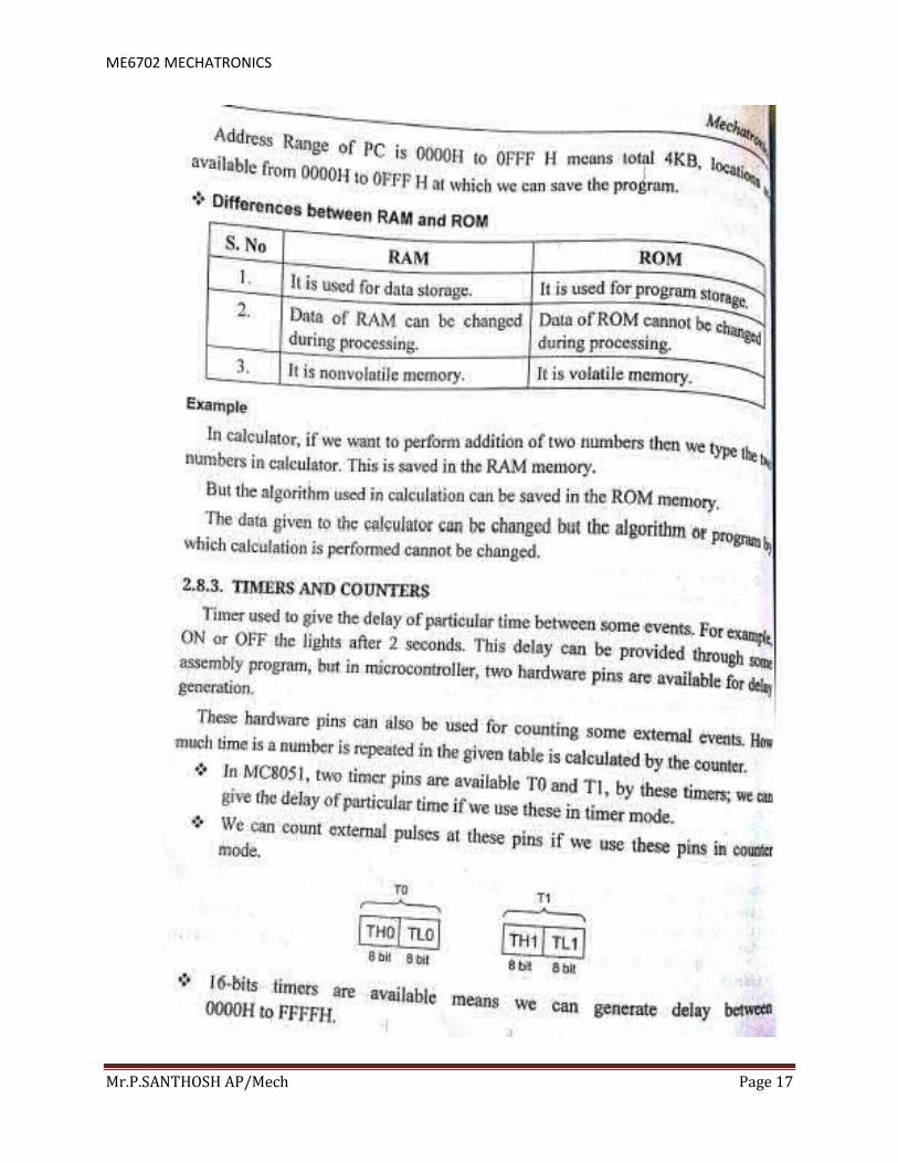
ME6702 MECHATRONICS
Mr.P.SANTHOSH AP/Mech Page 17

ME6702 MECHATRONICS
Mr.P.SANTHOSH AP/Mech Page 18

ME6702 MECHATRONICS
Mr.P.SANTHOSH AP/Mech Page 19
6. Explain the classification of instruction set of the microprocessor 8085.

ME6702 MECHATRONICS
Mr.P.SANTHOSH AP/Mech Page 20
7. Draw and explain the block diagram and operation of temperature controlling system
with a microprocessor.

ME6702 MECHATRONICS
Mr.P.SANTHOSH AP/Mech Page 21

ME6702 MECHATRONICS
Mr.P.SANTHOSH AP/Mech Page 22

ME6702 MECHATRONICS
Mr.P.SANTHOSH AP/Mech Page 23

ME6702 MECHATRONICS
Mr.P.SANTHOSH AP/Mech Page 24
8. Draw and explain the block diagram and operation of Traffic light controller with a
microprocessor.
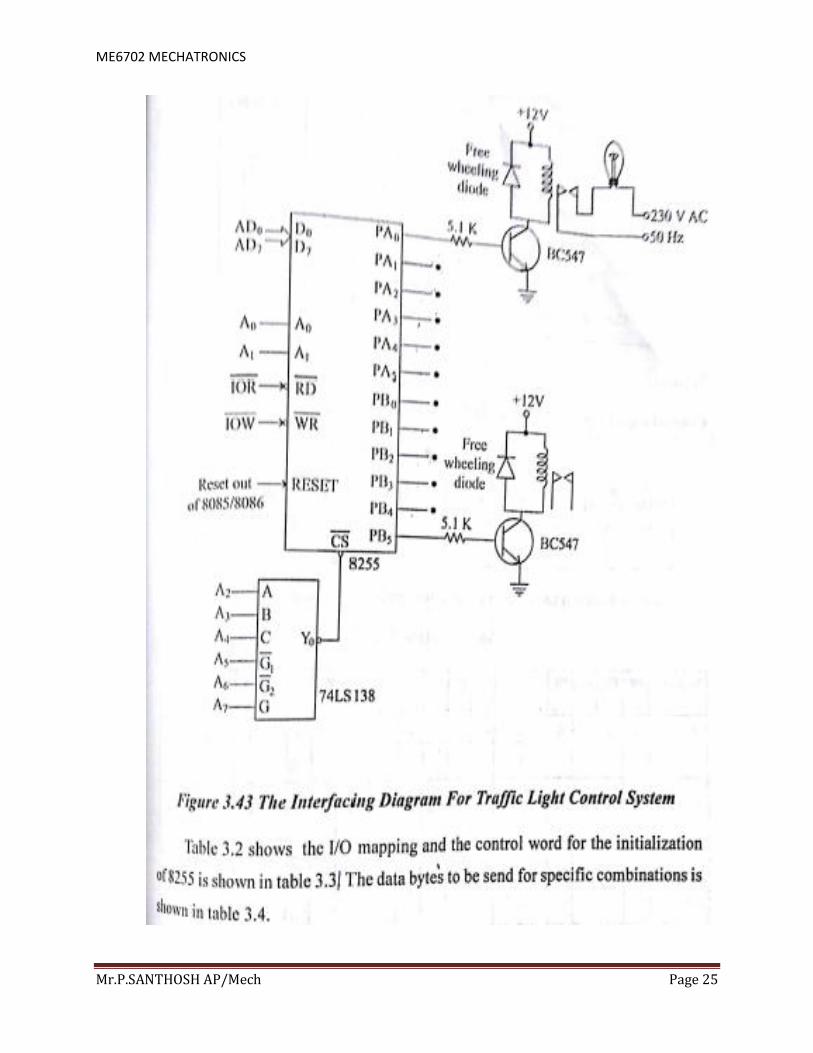
ME6702 MECHATRONICS
Mr.P.SANTHOSH AP/Mech Page 25

ME6702 MECHATRONICS
Mr.P.SANTHOSH AP/Mech Page 26

ME6702 MECHATRONICS
Mr.P.SANTHOSH AP/Mech Page 27
9. Describe with neat diagram the stepper motor control using microprocessor.

ME6702 MECHATRONICS
Mr.P.SANTHOSH AP/Mech Page 28

ME6702 MECHATRONICS
Mr.P.SANTHOSH AP/Mech Page 29

ME6702 MECHATRONICS
Mr.P.SANTHOSH AP/Mech Page 30

![and...Draw and explain functional block diagram of the 8086 micro- processor. [8] Explain with a neat diagram of memory segmentation in the 8086 microprocessor. Or [81 Draw and explain](https://img.pdfslide.us/doc/110x75/5e4eb30fd39dde0cf8262f40/and-draw-and-explain-functional-block-diagram-of-the-8086-micro-processor-8.jpg)
![(Time: [Marks: 75] muquestionpapers...with the help of relevant timing diagram. b. Explain how 8 DIP switches can be interfaced with 8 bit 8085 microprocessor. Draw a neat diagram](https://img.pdfslide.us/doc/110x75/6091bc8575cd9d62211404a3/time-marks-75-muquestionpapers-with-the-help-of-relevant-timing-diagram.jpg)


![QUESTION BANKsietkece.com/wp-content/uploads/2019/09/LICA-QB.docx · Web viewExplain the saw tooth wave generator with neat circuit diagram. [L2][CO4][5M] Draw the circuit diagram](https://img.pdfslide.us/doc/110x75/5e8ef85c56ceeb1018545b77/question-web-view-explain-the-saw-tooth-wave-generator-with-neat-circuit-diagram.jpg)


![[4658] – 158 - Savitribai Phule Pune Universitycollegecirculars.unipune.ac.in/sites/examdocs...[4658] – 158 SECTION – II 7. a) Explain the concept of monitor with neat diagram](https://img.pdfslide.us/doc/110x75/5abdae537f8b9add5f8b993a/4658-158-savitribai-phule-pune-univer-4658-158-section-ii-7-a.jpg)