Embed Size (px)
Citation preview

N O T I C E
THIS DOCUMENT HAS BEEN REPRODUCED FROM MICROFICHE. ALTHOUGH IT IS RECOGNIZED THAT
CERTAIN PORTIONS ARE ILLEGIBLE, IT IS BEING RELEASED IN THE INTEREST OF MAKING AVAILABLE AS MUCH
INFORMATION AS POSSIBLE
https://ntrs.nasa.gov/search.jsp?R=19810012566 2018-06-26T21:32:02+00:00Z
f
SPAC'E FABRICATION DEMONSTRATION SYSTEM
QUARTERLY PROGRESS REPORT NO. 10
September lo, 1979 - December 15, 1979
NASA-M.SFC Contract MD3 8-32472!r,
r
(6ASA-Cit-101704) SPACE rABHICATION N+31-21U95
DEMUNSTRATION SYSTEM Q g cu terly PioyrtssReport, 16 Sep. - 15 Dec. 1979 (Grumman
A:.•rospace Corp.) 11 p HC AOt/NF A01 130CSCL 21A GJ112
2121130
7
0
t t
00ORP MAT 50NmE1TIFwsOt.11^W vOlr^t 177Mi —1
Contract SO-3247$"Mary 3, 1980
National Aeronautics and Space MinistrationGeorge C. Marshall Space Flight CenterMarshall Space Flight hater, Alaboma 338612
Attention. Ericb E. Sngler, CMcode 8P613 SLag. 4610
Subject: SPA FAHRICATmN D- -- -BTRATMN S7BT1K -Quarterly Progress Report No. 20September 16, 1979 - December 15, 1979
References: (a) SFDS Monthly Progress Letter No. 21September 16, 1979 - October 15, 1979
(b) SFDS Monthly Progress Letter No. 22October 16, 1979 - November 15, 1979
Enclosure: (1) SFAS Induction Fastening
During this.reporting period, the Space FabricationDemonstration System (SFDS) program activity included:
o Composite Beam Cap Fabricator - This development effort,conducted at Goldsworthy Engineering Incorporated wascompleted within cost and close to the objectives ofthe abbreviated goals agreed to July 18, 1979 at NASk4WC.The final review meeting was held October 24, 1979. Detailassociated with the above is detailed in previous monthlyand quarterly reports including references (a) and (b).The final report submitted November 30, 1979.
o Flight Experiment Analysis - This effort directed atdesign and analysis of flight weight primary andsecondary beam builder structure has proceeded accordingto plan. The effort has currently been curtailed due tofunding limitations imposed with the authority to proceedAugust 1, 1979. Mechanical and structural preliminary
ANMOM
w►oa —.....
VC04FMI-Twol
design layouts and the subsystem requirementsare being completed. Details of these items have beenreported in references (a) and (b). Without addition lfad ing, this effort will be terminated during the actreporting period.
o Induction Fastening - These efforts implemented during thisquarterly reporting period have proceeded satisfactorilywithin cost and schedule. Details are included in references(a) and (b) as well as enclosure (1).
The periodic telecom and meeting& between cognisant programpersonnel have continued to assist in timely problea definition,discussion and resolution. These have definitely been instrumentalin keeping the program on target in achieving process developmentand general beam builder objectives within cost.
DISCUSSMN
WBS 1.1 PROMAK VANA4EtM
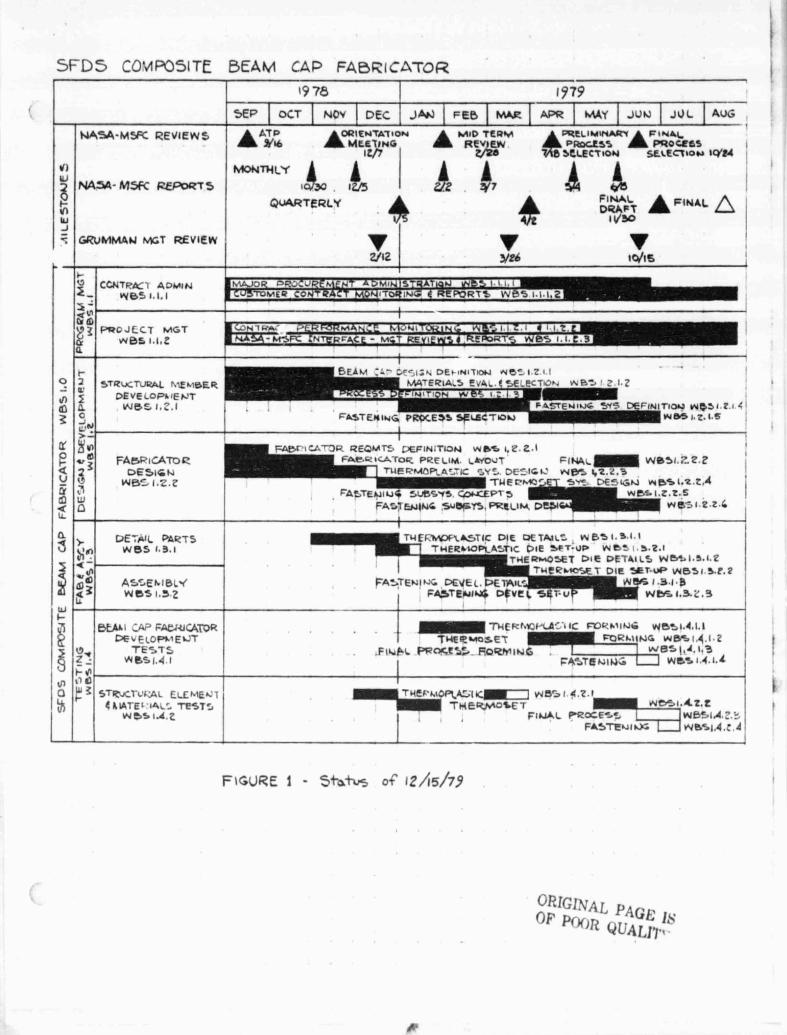
Figure .1 remains unchanged from that reported in reference (b).We continue to wait for NASA-MFC direction on final process formingand fastening demonstrations, and structural testing of these oracceptance of the final report on the Composite Beam Cap Fabricatordevelopment effort submitted November 30, 1979.
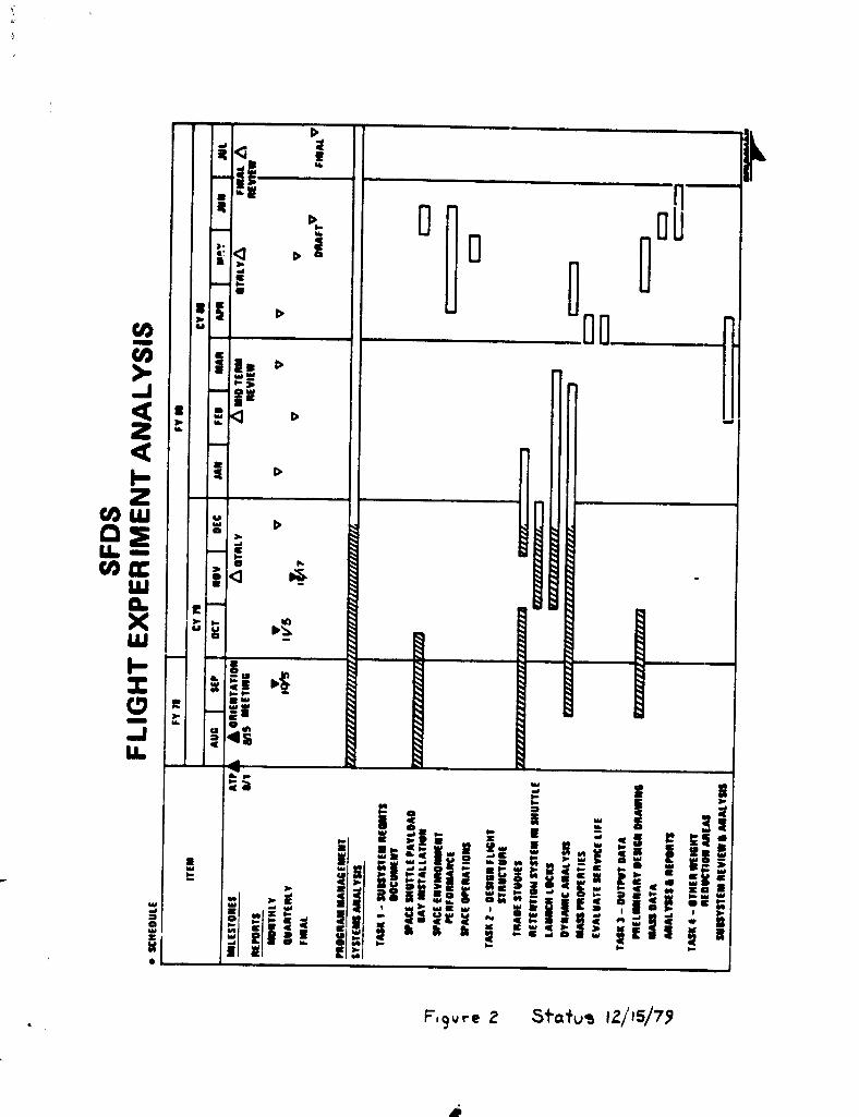
Figure 2 shows that the efforts associated with the FlightExperiment Analysis is on schedule. As noted above, we havecurtailed this effort at this point and will not proceed beyondthe completion of the preliminary mechanical and structural designlayouts and subsystems requirements document. Any further effortwill be held in abeyance until additional funding is releasedtoward this contract effort. Consequently, the effort completiondate will also slip on a month by month basis.
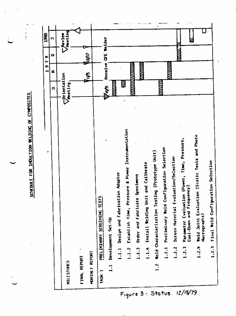
Figure 3 shows that theeffort is on schedule. Thisand enclosure (1), is within
effort planningeffort, detailedtarget cost.
for the Induction Fastening in references (a) and (b)

PASS._
tSS4WD&LRDD1
WBO 1.2 DEBIW AND DEV=PNMT
The Goldsworthy effort was completed during this quarterlyperiod and will no longer be reported on in this lint item.
The design and analysis effort associated with the Flightexperiment Analysis was reported on during this quarter inreference (a) and (b). Only the preliminary design UWout effortand subsystem requirements document are continuing as required.
The design of the test apparatus associated with theInduction Fastening effort was completed during this quarter andreported in references (a) and (b). No further design or developaenteffort is required at this time. Therefore, this effort will nolonger be reported under this line ites.
WBS 1.3 FAMICATIOe AMD ASS==
The Goldsworthy effort was completed during this quarterlyperiod. it will no longer be reported upon under this line item.
There is no effort associated with the Flight ExperimentAnalysis wader this line item.
The test apparatus associated with the Induction Fasteningk t effort was completed during this quarter and reported upon in
reference (b). Therefore, it will no longer be reported uponunder this line item.
WBS 1.4 TESTS
The Goldsworthy effort was completed during this quarterand reported on in references (a) and (b). This effort will noLonger be reported under this line item.
There is no testing associated with the Flight ExperimentAnalysis under this line item.
Testing associated with Induction Fastening has been reportedin reference (b) during this quarter. Test efforts are continuingand should be completed during the next reporting period. Additionaldata is discussed in enclosure (1).•
GR MMAN PAGE 4^CSS-SFDS-LRO01
CONCLUSIONS
Efforts at Goldsworthy Engineering Incorporated have beencompleted. We wait for further direction on the incompleteitems noted above and in reference (b) or acceptance of the finalreport as noted above.
The Flight Experiment Analysis effort has proceeded satisfact-orily, but will remain curtailed until further funding is madeavailable to complete the effort.
The Induction Fastening effort 1s proceeding satisfactorilyand remains within cost and schedule ::onstraints.
RECOMMENDATION
NASA MSFC respond to request for direction, acceptance and/orconcurrence with the program observations made above in connectionwith:
• Composite Beam Cap Fabricator development effort• Flight Experiment Analysis preliminary design effort
Continued close surveillance of all program elements by allcognizant program and project personnel.
Should you have any question with regard to the above, theenclosure or the SFDS program in general, please contact us.
Very truly yours,
GRUMMAN AEROSPACE-CORPORATION
jk6.
WKK : kf
cc: Distribution: NASA-MSFCNASA-LaRCGruosna.n
Goldsworthy
Walter K. MuenchSF'DS Program Manager
i
f
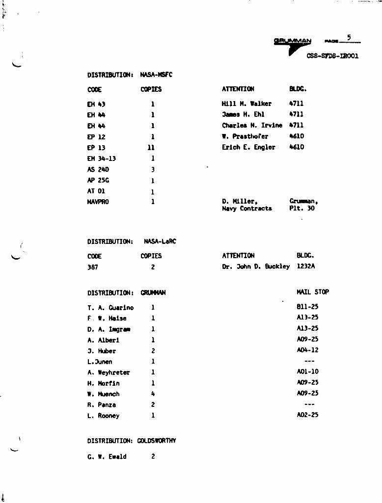
DISTRIBUTION: NASA-MSFC
CODE COPIES
EH 43 1
EH 44 1
EH 44 1
EP 12 1
EP 13 11
EM 34-13 1
AS 24D 3
AP 25G 1
AT O1 1
NAVPRO 1
5
A .,.a 5
CtSS SrD8-I1001
ATTENTION BLDG.
Hill N. Walker 4711
James H. Ehl 4711
Charles N. Irvine 4711
W. Prasthofer 4610
Erich E. Engler 4610
D. Miller, Grumman,Navy Contracts Plt. 30
DISTRIBUTION: NASA-LaRC
CODE COPIES
ATTENTION BLDG.
387 2
Dr. Sohn D. Buckley 1232A
DISTRIBUTION: GRUMMAN
T. A. Guarino 1
F W. Haise 1
D. A. bWam 1
A. Alberi 1
J. Huber 2
L.Junen 1
A. Weyhreter 1
H. Mortin 1
W. Muench 4
R. Panza 2
L. Rooney 1
DISTRIBUTION: GOLDSWORTHY
G. W. Ewald 2
MAIL STOP
Bll-25
A13-25
A13-25
A09-25
A04-12
A01-10
A09-25
A09-25
A02-25
^_ CC;NTPCC'I .4DMINWBS 1.1,I
Q ^^d LDPRGJLCT MGT
w05 1.1.:
Or
STRUCTURAL Nifl.13ER= a DEvELDP► 1ENTIp Z. Wg£ I•..I
C`^ N
v 3 FAMPICATORQ ^ DESIGNU I' w$_ 1.2.2^ wQU.
Q > UE'NIL PAkTSv Son W55 1.3.1
^LnAS' ENIBL-Iy^ m m
fall 4 3 wC51.^2Iu
btAA I `AP FACl4lG4T0RL DE V ElOPME ►JT
0r TE-.-TS? W SS 1. 4.1
N 0OO ^; STR,CIL'cAL EL£^IEN1
A LATE I " IAL, TESTSw 5S l.A. Z
SEP OCT NOV I DEC FEB IMAR
-ATP ClR1ENTAT^ON
9116 - A MID TF-QNAMEET/NO
I t/yREVIEW
Z/7eMONTHLY
QUARTERLYI ^
4
v vZ/Iz -V26
5FD5 CO'31R05ITE
NA'5A-M5FC REVIEWS
VI
NASA- M5ft REPoRT5
I•-VIWJ
GRUMMAN MGT REVIF-W
BEAM CAP FABRICA'\TOR
1-19 78 1979
APR I MAY I JUN Jul I AUGt
7+PitP-IIMInAR`IF W4LPROGE5S - PRoczes
8 5GLECT$ON SELECTION IWA
A iFINAL- FINAL QDRvA
vlo/Is
:ESIEP11S1^ ^ 5 S 1. I, C,3 I
^lih DEr^N^TION Ne _ 1.2 LI44TE41A,5 !'VA,. '-1?CTION wB, ' : I.Z
_ r^ i _
I"--
F^^TENiIJF L'. ^, DE F INI TIC WQ,1. ?.I ^I
FATTENING PROCE5S SELECT&OW wbS .2. 1•S Ii
I
Ai"a
MFINITIDN w^41,Z.ZAr, PRELIM. LNO IJT FINA^^ W051•T..2.2RMDPLA 711 ^Y`-, DE_•IGI, WAS 1,2.Z.3
TNE^MC` 5e-! L^Enu,- w wBSI.z.Z.4
FA;,TEI,,IIU^ :,II^SY^ CpNCEP^ S wDS I.Z.2.5FA:.7Ey,11NG Svbr-Y ,5,PRELIM. 2.z G
i
TNE^1r1pGlUTIC DIE C)U-TAp LL "E5IJ1.1.1.1THER ► IOPLA`,TIC DIE 5fT - UP wC` D.z.I
THEa^IOSET DIE DETAILS W^ I•^•1•?TwFc ► IC^^ET DIE SET-UP vdM51 5.1.?
FATTENING DEVEI. Df11AIL' WAS 1 .3 .1 I 8FASTE4ua^* DEVE^ 5 v Wt5os— 1.3.L.3
4 ^ Tuc^r.a ►-ut^^11c crol•'A t INIG we^l.^.l.l IT ►dER^SET FOR ►.IING w6S 1.4.1 2
FI ►rpL F'RME 41 FORM ING wESSI,^.I,j' FIST^NIN:oI I wMS1.4.I.LI
THE E I,IOPLA.^,(1lMNl= v14 l !i.z.1
I , Flw^.l PROCE ^S wlrS1A•Z.'^
FASTEN II.)G wesl.l.c.I
FIGURE 1 - St-ot,s of 12/5/79
ORIGINAL pace ISOF Pf)()R
QUgL1'J•1
Aw
0
D
r^
Drsd
p e
e0
31- D
!^_I ya 11 D
JeQ = Dz ar
Q s D
ZCO2Q W W
O Y D
U
co) cc es d
►LU
x u u ►^W
~_ ' b.
I ►3- W
r O
U.
o^o ^ you
o^
r
11
f
E^k
[.—W.7Q2
< = W d
O
W W W L W O ^! = ^• O W W
! • W
s Y L_ w WW O OM Y-C OI O ^!W i 1 Y W yL^ W 1 W
M
Fl9vre 2 Status 12115179
$W4 Aj
u
y
^VCh
f0%
-•• _M
0., ccV top0 Cm
O C +1 ^.-.4 u
WN1^1N
1u
c0
^v VLd
rZZp-^
CC_
a+ 0 V Cy^ .0 v V
d^0
H VV O h
uLa
o
a° c
cu
AjCL I ..,r0 .O
-44jI0 C
6 vN
Q< V V Z7
L.
''' Oate+ a
uv O>^
v .nl
W 41
m U.^ ^ ^ c u ;^ Gov > 0v .^ t c
WA N ; .Nr c Z v; •Cr A O
^ V E C°
^ CO S rl9 „+
^c W o «c a 49 a g s^ "0
^ u ..^ N P1 .Y ^
•-1C. rl ..r ^ rl ^ ••1 ^ •^
' NW. ,..^ N
-4 .-4 ^^LAW
^
h"'
^ ~= ~WC
F,9ure 3 - Status 121*79
i
ENCT;ZURE (1)
INDUCTION FASTENING
L.
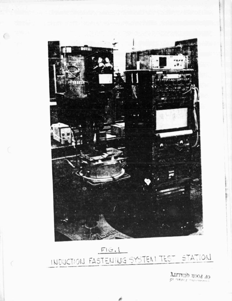
IINDUC':ION FASTENING OF GRAPHITE: REINFORCED COMPOSITES
Test of the IARC prototype induction welder is continuing in an instru-
a.mented test stand. This test stand is comprised of a Dumore drill press (air
over oil feed for variable applied loads) and a dynamometer to measure actual
welding loads. The dynamometer output signal is fed to a Brush strip chart
recorder for permanent record. The supplied L4RC induction welder has typical
operating characteristics of 120 K-Hertz and 60 watts power.
Continued testing has shown that the inter ace screening must be well
impregnated with resin to ensure proper flow when bonding graphite/acrylic lap
shear samples. Specimens have also been prepared from 0.030-inch thick graphite/
polyethersulfone for future induction fastening evaluation. These samples will
differ from the graphite/acrylic in that polyethersulfone film will be ustd
in conjunction with steel screening Lt the lap shear interface.
^ I ^^-r l
C7! FA
^rnl^^ }Irma .^o
/p
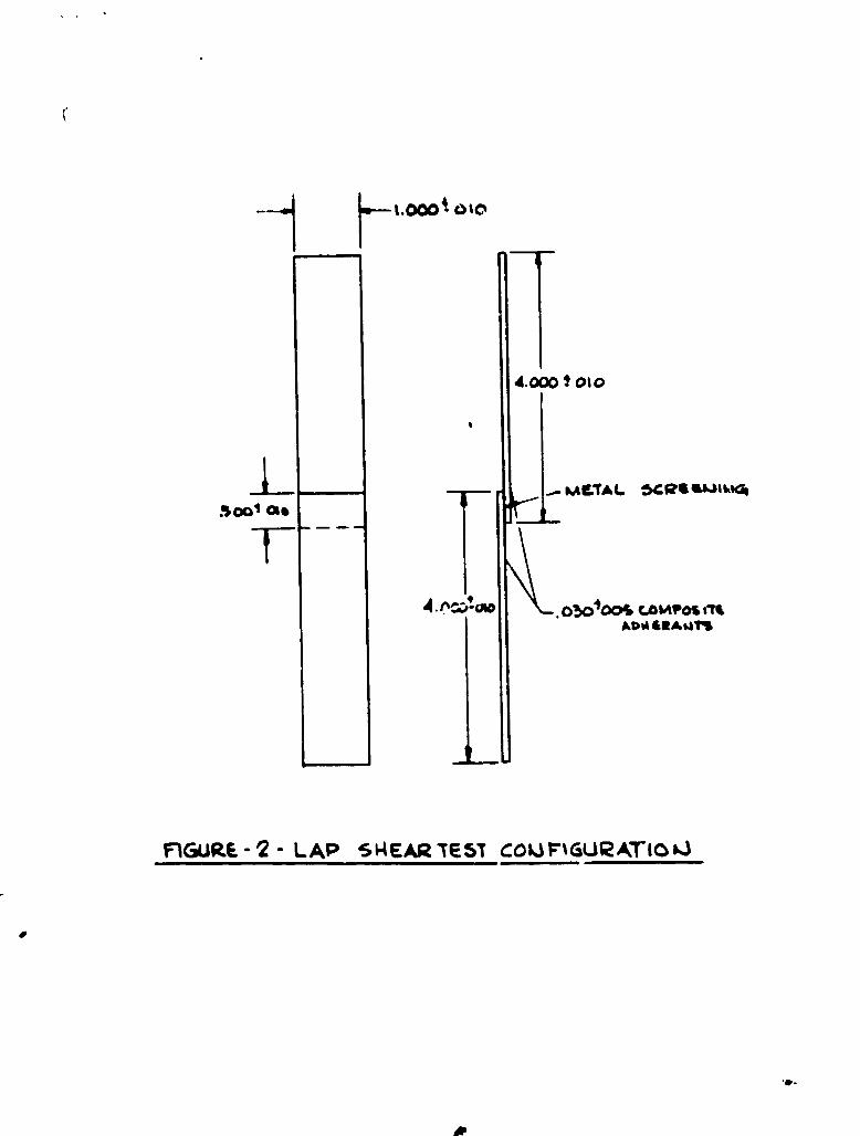
1.000 1 0 to
4.000 ! 010
KACTAL 5CQG% lkWq
500,016
T-
. n ,'-aa . 050^00& c o MPOS ATEADM &R^MT!
FIGURE • 2 • LAP S H EAR TEST COUF%GURATIO0
R


![Sfas dts help final[1]](https://img.pdfslide.us/doc/110x75/55858fb0d8b42aca7b8b46d5/sfas-dts-help-final1.jpg)