Embed Size (px)
Citation preview
This copy is a reprint which includes current pagesfrom Changes 1.
*TB CML 100
DEPARTMENT OF THE ARMY TECHNICAL BULLETIN
SMOKE POT, HC, 10-lb., M1, and 30-lb., ABC-M5;SMOKE POT, FLOATING, HC, M4A2; SGF2, AN-M7;
and SGF2, AN-M7A1Refs: FM 3-50, FM 5-25; SR 55-73O-10; TM 3-215, TM 3250
Headquarters, Department of the Army, Washington, D.C.6 April 1964
SAFETY PRECAUTIONSWhen igniting a smoke pot manually, keep the head well to one side of the top of the pot and out of the way of
sparks or flame.Do not use the pull ring or safety pin on the fuze for lifting or handling smoke pots.Vent burning-type (HC) floating smoke pots for at least 5 minutes within 24 hours before firing by removing adhesive
tape from two vent holes in the inside cover. Recover the holes with adhesive tape before firing smoke pots.Do not remove the tape covering the smoke-emission holes in thermal generator-type (SGF) smoke pots.Use a 4- to 6-foot pole when moving a misfired pot immediately following the first ignition attempt. After 5 minutes,
the misfired pot can be moved safely by hand.When authorized to burn smoke pots to prevent enemy use, be sure that smoke from the pots does not interfere
with the operations of nearby tactical units.Wear a protective mask when exposed to a high concentration of HC smoke, when exposed for a prolonged period
to an ordinary field concentration of HC, or when exposed for a prolonged period to a high concentration of SGF.When training with smoke pots, take precautionary measures against accidental fires.
Paragraph PageSECTION I. INTRODUCTION
Scope ------------------------------------------------------------------------------------ 1 2Purpose---------------------------------------------------------------------------------- 2 2
II. GENERAL INFORMATIONSmokes ---------------------------------------------------------------------------------- 3 2Difference in models------------------------------------------------------------------ 4 2Methods of firing----------------------------------------------------------------------- 5 4
________* This bulletin supersedes so much !of TM 3-300, 14 August 1956, including C 2, 5 May 1958, C 3, 25 August 1959,
and C 5, 24 May 1962, as pertains to smoke pots.
TAGO 8556A - Apr
1
Paragraph PageSECTION II. Misfires ---------------------------------------------------------------------------------- 6 5
Concealing glare of burning pots -------------------------------------------------- 7 5III. BURNING-TYPE SMOKE POTS
Smoke Pot, HC, 10-lb., M1 --------------------------------------------------------- 8 6Smoke Pot, HC, 30-lb., ABC-M5 -------------------------------------------------- 9 8Smoke-Pot, Floating, HC, M4A2--------------------------------------------------- 10 9
IV. THERMAL GENERATOR-TYPE SMOKE POTSSmoke Pot, Floating, SGF2, AN-M7---------------------------------------------- 11 12Smoke Pot, Floating, SCGF2, AN-M7A1 ---------------------------------------- 12 13Filling and fusing----------------------------------------------------------------------- 13 13Ignition ----------------------------------------------------------------------------------- 14 13Functioning ----------------------------------------------------------------------------- 15 14
V. MARKING AND PACKINGMarking ---------------------------------------------------------------------------------- 16 16Packing ---------------------------------------------------------------------------------- 17 16
VI. SHIPMENT, STORAGE, AND DEMOLITION TOPREVENT ENEMY USEShipment -------------------------------------------------------------------------------- 18 16Storage ---------------------------------------------------------------------------------- 19 16Firefighting ------------------------------------------------------------------------------ 20 16Demolition to prevent enemy use ------------------------------------------------- 21 16
1. Scope. This bulletin describes Smoke Pot, HC,10-lb., M1, and HC, 30-lb., ABC-M5; and Smoke Pot,Floating, HC, M4A2; SGF2, AN-M7; and SGF2, AN-M7A1. It also gives information on their handling,functioning, storage, shipment, and destruction.
2. Purpose. Smoke pots are designed to producelarge volumes of screening smoke. Floating smoke pots
can be used either on land or water; the others can beused only on land. For employment of smoke pots, seeFM 3-50, Chemical Smoke Battalion and ChemicalSmoke Generator Company.
Section II. GENERAL INFORMATION
3. Smokes. Type C HC smoke mixtures and fogoil are the smoke-producing agents (TM 3-215) used inthese smoke pots.
a. Type C HC Smoke Mixture. Type C HC smokemixture (used in the M1, ABC-M5, and M4A2 smokepots) consists of approximately 47 percenthexachloroethane, 47 percent zinc oxide, and 6 percentgrained aluminum.
b. Fog Oil. Fog oil is a petroleum oil used to fill AN-M7 SGF2 and AN-M7A1 SGF2 floating smoke pots(thermal generator smoke pots). Depending on theoperating temperature (table I), two grades are used.SGF1, which has approximately the same viscosity asSAE 40 motor oil, is used when the operatingtemperature is above 90° F. SGF2, which hasapproximately the same viscosity as SAE 10 motor oil, isused when the operating temperature is 0° F. to 90°F. Ifthe operating temperature is below 0° F., kerosene isadded to dilute the SGF2.
Table I. Filling for Thermal GeneratorSmoke Pots
Operating Recommendedtemperature (°F.) filling
Above 90 SGF1Zero to 90 SGF2Zero to -25 3 parts SGF2, 1 part
kerosene-26 to -40 Equal parts SGF2, 1 and
kerosene
4. Difference in Models. a. Smoke pots areessentially portable steel containers filled with a smoke-producing agent. An essential difference between land-type smoke pots and floating
AGO 8556A
2
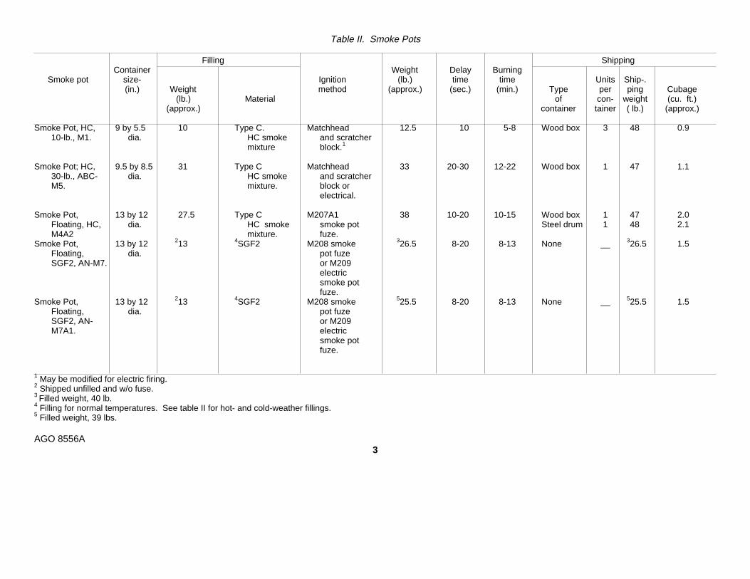
Table II. Smoke Pots
Filling ShippingContainer Weight Delay Burning
Smoke pot size- Ignition (lb.) time time Units Ship-.(in.) Weight method (approx.) (sec.) (min.) Type per ping Cubage
(lb.) Material of con- weight (cu. ft.)(approx.) container tainer ( lb.) (approx.)
Smoke Pot, HC, 9 by 5.5 10 Type C. Matchhead 12.5 10 5-8 Wood box 3 48 0.910-lb., M1. dia. HC smoke and scratcher
mixture block.1
Smoke Pot; HC, 9.5 by 8.5 31 Type C Matchhead 33 20-30 12-22 Wood box 1 47 1.130-lb., ABC- dia. HC smoke and scratcherM5. mixture. block or
electrical.
Smoke Pot, 13 by 12 27.5 Type C M207A1 38 10-20 10-15 Wood box 1 47 2.0Floating, HC, dia. HC smoke smoke pot Steel drum 1 48 2.1M4A2 mixture. fuze.
Smoke Pot, 13 by 12 213 4SGF2 M208 smoke 326.5 8-20 8-13 None __ 326.5 1.5Floating, dia. pot fuzeSGF2, AN-M7. or M209
electricsmoke potfuze.
Smoke Pot, 13 by 12 213 4SGF2 M208 smoke 525.5 8-20 8-13 None __ 525.5 1.5Floating, dia. pot fuzeSGF2, AN- or M209M7A1. electric
smoke potfuze.
1 May be modified for electric firing.2 Shipped unfilled and w/o fuse.3 Filled weight, 40 lb.4 Filling for normal temperatures. See table II for hot- and cold-weather fillings.5 Filled weight, 39 lbs.
AGO 8556A3

smoke pots lies in the ratio of total bulk of the smoke potto bulk of smoke-producing agent. Floating smoke potsare not completely filled with agent; voids in the containerpermit the pots to float in water.
b. For ease of presentation, the smoke potscovered in this bulletin will be considered as burning type(those filled with HC smoke mixtures) or thermalgenerator type (those filled with SGF fog oil).
c. Specific data on the smoke pots described inthis bulletin are given in table II.
5. Methods of Firing. a. Single Ignition. Smokepots can be ignited singly by using the means of ignitionsupplied with each pot. The M1 smoke pot is designedfor manual ignition but may be modified for electricignition. The ABC-M5 smoke pot has an integral electricignition device in addition to a friction igniter and can beignited either manually or electrically. Floating smokepots are ignited by igniting fuzes. Two of the floatingsmoke pots, the AN-M7 and the AN-M7A1, can be fittedwith M209 electric smoke pot fuzes for electric ignition.Circuits and connections for electric ignition are thesame as for demolitions (FM 5-25).
b. Multiple Ignition. When a number of M1 or ABC-M5 smoke pots must be ignited simultaneously atdifferent locations, they can be prepared for electricignition and connection into an electric firing circuit asdescribed in FM 5-25 and in paragraphs 8c and 9c. TheAN-M7 and AN-M7A1 floating smoke pots can also beignited electrically in multiple when the M209 fuze isused.
c. Chain Ignition. A number of M1 or ABC-M5smoke pots can be arranged to ignite in succession, thusproviding smoke for a longer period than is possibleusing a single pot. To accomplish chain ignition, the potscan be placed in stacks (fig. 1) and the topmost pot inthe stack ignited, or they can be laid on their sides (fig.2) end to end and the pot with the exposed ignitingdevice ignited. Prior to stacking, the outer covers mustbe removed from all pots so that the igniting devices areexposed. When M1 smoke pots are stacked vertically,supports must be provided for stability. The ABC-M5smoke pot is especially designed for vertical stacking,and because the bottom of one pot fits snugly into thetop of the one below it, no support is required. Whetherpots are stacked vertically or laid on their sides, the heatgenerated by one burning pot in a series ignites the
adjacent pot. The total burning time of a series of smokepots ignited by chain ignition is slightly less than the sumof the individual burning times, because each pot ignitesshortly before
Figure 1. ABC-M5 smoke pots stacked vertically.
Figure 2. ABC-M5 smoke pots laid end to end.
AGO 8556A
4
the pot ignited previously is completely burned out.
6. Misfires. HC smoke pots which have misfiredduring normal ignition can be ignited by placing theignition device in the misfired pot next to a burning potand igniting the misfired pot by chain ignition (par. 5c).
Warning: Use a 4- to 6-foot pole when moving amisfired pot immediately following the first ignitionattempt. After 5 minutes, the misfired pot can bemoved safely by hand.
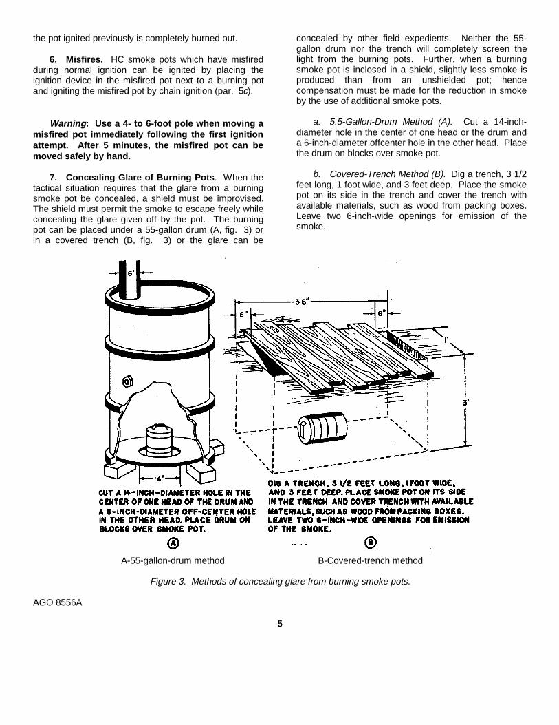
7. Concealing Glare of Burning Pots. When thetactical situation requires that the glare from a burningsmoke pot be concealed, a shield must be improvised.The shield must permit the smoke to escape freely whileconcealing the glare given off by the pot. The burningpot can be placed under a 55-gallon drum (A, fig. 3) orin a covered trench (B, fig. 3) or the glare can be
concealed by other field expedients. Neither the 55-gallon drum nor the trench will completely screen thelight from the burning pots. Further, when a burningsmoke pot is inclosed in a shield, slightly less smoke isproduced than from an unshielded pot; hencecompensation must be made for the reduction in smokeby the use of additional smoke pots.
a. 5.5-Gallon-Drum Method (A). Cut a 14-inch-diameter hole in the center of one head or the drum anda 6-inch-diameter offcenter hole in the other head. Placethe drum on blocks over smoke pot.
b. Covered-Trench Method (B). Dig a trench, 3 1/2feet long, 1 foot wide, and 3 feet deep. Place the smokepot on its side in the trench and cover the trench withavailable materials, such as wood from packing boxes.Leave two 6-inch-wide openings for emission of thesmoke.
A-55-gallon-drum method B-Covered-trench method
Figure 3. Methods of concealing glare from burning smoke pots.
AGO 8556A
5
Section III. BURNING-TYPE SMOKE POTS
8. Smoke Pot, HC, 10-lb., Ml. a. Description.The M1 smoke pot (fig. 4) is a cylindrical sheet-metalcontainer, 51/2 inches in diameter by 9 inches high, filledwith approximately 10 pounds of type C HC smokemixture and provided with an ignition device. Aremovable outer cover, which protects the contentsduring storage and shipment, is clamped to the top of thepot by a metal clamp and is sealed with adhesive tape.A nonremovable inner cover with a hole in its centercovers the filling. A plastic cup containing a startermixture is embedded in the filling directly under the holein the inner cover. A matchhead is centered in the holein the inner cover in contact with the starter mixture. Ascratcher block in a paper envelope is packed betweenthe outer and inner covers.
b. Manual Ignition.(1) Single. To prepare an M1 smoke pot for
manual ignition, strip off the adhesive tapeand clamp. Remove the outer cover toexpose the matchhead and take thescratcher block from its envelope. To ignite,draw the scratcher block rapidly across thematchhead. The matchhead ignites thestarter mixture which in turn ignites the HCfilling. After a delay of approximately 10
seconds, smoke is produced for 5 to 8minutes.
(2) Chain. Remove the outer covers from therequired number of pots, stack the potsvertically, or lay them end-to-end horizontallyand ignite one pot.
c. Electric Ignition (fig. 5).(1) An M1 flash-vented electric squib is used to
ignite the M1 smoke pot electrically. (Thissquib is not a component of the M1 smokepot; it is issued separately.) To ignite the pot,connect the lead wires from the squib to asource of electric current.
(2) To prepare the M1 smoke pot for electricignition, remove the tape, clamp, and cover(A). Remove the sealing compound usingthe clamp as a scraper (B). Place a squibbeside the matchhead with one hole in thesquib facing the matchhead (C). Cover thesquib
Figure 4. M1 10-lb. HC smoke pot.
AGO 8556A
6
Figure 5. Preparing Ml smoke pot for electric ignition.
AGO 8556A
7

and matchhead with a piece of thewaterproof tape which was removed fromthe cover. Tape the squib lead wires to thecover with a second piece of tape (C). Makea shallow dent in the lip of the cover (D) ;then press the cover firmly in place allowingthe squib lead wires to pass under the dent.Seal the junction between the pot and thecover with sealing compound using theclamp as an applicator (E). Make a halfhitch around the pot with the squib leadwires and fasten the clamp around the potabove the half hitch to hold wires in place(F).
9. Smoke Pot, HC, 30-lb., ABC-M5. a.Description. The ABC-M5 smoke pot (figs: 6 and 7) is acylindrical sheet-metal container, 81/2 inches in diameterby 91/2 inches high, filled with approximately 30 poundsof type C HC smoke mixture and 1 pound of fast-burningsmoke mixture. The bottom of the container is taperedto a diameter of 81/4 inches to permit stable stacking.The pot is covered by a non-removable outer cover witha circular tear strip. Two binding posts, which aremounted on the outer cover, are connected internally bytwo lead wires to two electric squibs. A carrying handleis mounted on the outer cover. An inner cover with a
circular hole in its center covers the filling. A plastic cupcontaining a starter mixture is embedded in the top of thefilling under the hole in the inner cover. A matchheadwhich is centered above the starter mixture is accessiblewhen the tear strip is removed. A scratcher block in apaper envelope is packed between the inner and outercovers.
b. Manual Ignition.(1) Single. Expose the matchhead by pulling
the tear strip handle upward and move thescratcher block quickly across thematchhead. Flame from the matchheadtravels to the starter mixture which in turnignites the HC filling. After a delay of 20 to30 seconds, smoke is produced for 12 to 22minutes.
(2) Chain. Remove tear strips from all pots;then stack the pots (par. 5c) by fitting thebottom of one into the top of the next. Whenthe stack is complete, ignite the end pot.
c. Electric Ignition. ABC-M6 smoke pots can beignited singly or in multiple by electric ignition. Toprepare for electric ignition, connect wires from thepower source to the binding
Figure 6. ABC-M5 30-lb. HC smoke pot.
AGO 8556A
8
Figure 7. ABC-M5 smoke pot prepared for manual ignition.
posts. (It is not necessary to remove the tear strip whenfiring pots electrically.) When the electric circuit iscompleted, the squib ignites the matchhead which in turnignites the starter mixture. The burning starter mixtureignites the HC filling which generates sufficient heat tosoften the, solder holding the tear strip. Internalpressure blows off the tear strip allowing the smoke toescape. When firing the ABC-M5 smoke pot electrically,fire the pots from a position a short distance from theinstallation. A 6-volt source is required to ignite anumber of smoke pots simultaneously, but a 1 1/2-voltflashlight battery can be used to ignite a single smokepot. Use two batteries in series if the connecting wire isof higher resistance than the squib in the smoke pot. Toignite a pot in this manner, attach a wire not more than
10 feet long to each of the two binding posts of thesmoke pot. Stretch the wires their full lengths beingcareful not to pull them from the binding posts and touchthe free end of one wire to the center terminal of thebattery and free end of the other wire to the base of thebattery, closing the circuit.
10. Smoke Pot, Floating, HC, M4A2. a.Description.
(1) The M4A2 HC floating smoke pot (fig. 8) is ametal container, 12 inches in diameter by 13inches high. The lower third of the potcontains approximately
AGO 8556A
9
27 1/2 pounds of HC smoke mixture. Awaterproof outer cover secured to the pot bya quick-release clamp keeps moisture out ofthe pot and protects the fuze. A steelcarrying handle is attached to the outercover. A dish-shaped inner cover covers thefilling and provides a mounting for a fuzeadapter. Three ventholes in the inner coverare covered with adhesive tape. A steelhandle is attached to the inner cover forcarrying the smoke pot after the outer covershas been removed.
(2) Starter mixture in a plastic cup is embeddedin the smoke mixture. The filling isseparated from the air chamber above by aplastic closure disk held in place by a metalretainer.
(3) The M207A1 smoke pot fuze (fig. 9) isscrewed into the fuze adapter in the innercover. An igniter tube extends downwardfrom the lower end of the fuze adapter to thestarter mixture.
b. Operation and Functioning. Remove the quick-release clamp and outer cover, exposing the fuze. Holdthe safety lever (fuze lever) firmly against the fuze bodyand withdraw the safety pin (fig. 10). Lift the pot by itshandle and drop it into the water releasing the safetylever. When the safety lever is released, the striker,driven by the striker spring, hits the primer. The primerignites the first-fire charge which in turn ignites the delaycharge. After 1.2 to 2 seconds, the delay charge ignitesthe ignition charge, completing the fuze action. Flamefrom the ignition charge travels through the igniter tubeto the starter mixture which in turn ignites the HC filling.Pressure builds up inside the pot and blows off theadhesive tape covering the vents in the inner cover.Total delay time from release of the safety lever untilsmoke production begins is 10 to 20 seconds. Thesmoke pot burns for 10 to 15 minutes.
Warning: Vent M4A2 HC floating smoke pots forat least 5 minutes within 24 hours before firing byremoving adhesive tape from two ventholes in theinside cover. Recover the holes with adhesive tapebefore firing smoke pots.
Figure 8. M4A2 HC floating smoke pot.
AGO 8556A
10
Figure 9. M207A1 floating smoke pot fuze.
Figure 10. Firing the M4A2 HC floating smoke pot.
AGO 8556A
11

Section IV. THERMAL GENERATOR-TYPE SMOKE POTS
11. Smoke Pot, Floating, SGF2, AN-M7. a. Body.The body of the AN-M7 floating smoke pot (fig. 11) is ametal container 12 inches in diameter by 13 inches high.The upper portion of the body is rubbed; the base of thebody is slightly tapered to facilitate stacking in storage.An outer cover with a carrying handle attached isfastened to the pot by a ring clamp. A dish-shaped innercover (fig. 12) with a carrying handle attached isfastened to the body by lugs and steel strapping. A fuzeadapter (2, fig. 13) in the center of the inner coverprovides a seat for the fuze (18). Three ventholes,spaced equally around the fuze adapter, provide outletsfor the smoke. When the pot is shipped, the ventholesare sealed with adhesive tape and a plastic plug (fig. 12)is screwed into the fuze opening in the adapter.
b. Interior (fig. 13). An air chamber (4) below theinner cover (3) occupies the upper third of the body.Three sinkholes (5), 1/8 inch in diameter, are cut in theside of the air chamber and are sealed with a low-melting-point solder (7). An oil chamber (8) directlybelow the air chamber is separated from it by an airpartition (17). The oil chamber extends to the bottom of
the pot. A filling hole (14) in the side of the container,which is used when filling the pot with fog oil prior to use,is closed by a screwplug. Inside the oil chamber, a fuelchamber assembly, consisting of a fuel chamber (12),venturi tube (16), pressure tube (6), and oil feed tube(15), is crimped to the bottom of the body and sealedwith a plastic compound. The fuel chamber contains afuel block (9) consisting of a slow-burning fuel mixturecovered by a thin layer of fast-burning fuel mixture. Thefuel mixtures are composed of varying proportions ofammonium nitrate, charcoal, and wax. A doughnut-shaped ring of starter mixtures (10) is embedded in thetop of the fuel block. The venturi tube extends from thetop of the fuel chamber, through the oil chamber, andinto the air chamber. The oil-feed tube is connected tothe side of the venturi tube and extends to the bottom ofthe fog oil chamber, where it is covered by a screen (13).The point of connection between the oil-feed tube andthe venturi tube is sealed with a low-melting-point solderseal (11). The pressure tube (6) is
Figure 11. AN-M7 SGF2 floating smoke pot.
Figure 12. AN-M7 SGF2 floating smoke pot with outercover removed.
AGO 8556A
12

connected to the top of the fuel chamber and extendsabove the surface of the oil in the oil chamber. The fuelchamber end of the pressure tube also is sealed with alow-melting-point solder seal (7).
c. Fuzes. Either an M208 floating smoke pot fuze(fig. 14) or an M209 electric floating smoke pot fuze (fig.15) can be used to ignite the smoke pot.
12. Smoke Pot, Floating, SGF2, AN-M7A1. TheAN-M7A1 SGF2 floating smoke pot is an improvedversion of the AN-M7 smoke pot. In addition to severalinternal improvements, such as the use of a threaded(not brazed-on) venturi which facilitates assembly and animproved fuel block, there is an additional sinkhole in thebottom on the AN-M7A1 smoke pot. All sinkholes arelocated so that water does not cool the solder seals as itsometimes does in the AN-M7 smoke pot.
1 Outer cover 10 Starter mixture2 Fuze adapter 11 Solder seal3 Inner cover 12 Fuel chamber4 Air chamber 13 Screen5 Sinkholes 14 Filling hole and plug6 Pressure tube 15 Oil-feed tube7 Solder seal 16 Venturi tube8 Oil chamber 17 Air partition9 Fuel block 18 Fuze
Figure 13. Components of AN-M7 SGF2floating smoke pot.
13. Filling and Fuzing. Thermal generator-type(SGF) floating smoke pots are normally shipped todepots unfilled and unfuzed. Fog oil and fuzes areshipped separately.
a. The oil filling procedure may be varieddepending on the available facilities and on the numberof pots be filled. When filling a large number of pots atone time, it may be desirable to connect several drumsof oil to a filling manifold having a number of drawoffstations. In a smaller operation, oil may be drawndirectly from a valve screwed into the end of an oil drum.See table I for the type of fog oil or mixture to be used atvarious temperatures.
b. When filling a pot with oil, leave the outer coverclamped on. Fill as follows:
(1) Lay the pot on its side with the filling holeuppermost and place chocks at both sides toprevent the pot from rolling.
(2) Remove the filling plug and asbestos gasketfrom the pot. Keep the gasket in place onthe plug to prevent its loss.
(3) Pour oil into the oil chamber to the level ofthe bottom of the fitting in the filling hole.Approximately 13 pounds of oil will fill the oilchamber to this level and will leave thenecessary void.
(4) Strew the filling plug and gasket in the fillinghole and tighten the plug with a wrench.
c. To fuze the smoke pot, remove the ring clampand outer cover, unscrew the plastic plug from the fuzeadapter, and screw an M208 floating smoke pot fuze oran M209 electric floating smoke pot fuze handtight intothe fuze opening in the adapter. Do not remove the tapecovering the smoke-emission holes.
Warning: Do not use pull ring or safety pin onfuze for lifting or handling the pot.
14. Ignition. a. On Water. Hold the fuze safetylever on the M208 fuze firmly against the fuze body andwithdraw the safety pin. Lift the pot by its handle anddrop it into the water, releasing the safety lever.
b. On Land.
(1) Manual ignition. Place the smoke pot in thedesired location and withdraw
AGO 8556A
13
Figure 14. M208 floating smoke pot fuze.
the safetypin, releasing the safety lever.
(2) Electric ignition. Only smoke pots equippedwith an M209 electric floating smoke potfuze can be ignited electrically. To ignite thepot electrically, connect the wires from thefuze to an electric firing circuit. When anelectric current flows through the fuze, thefuze ignites.
15. Functioning. a. With M208 Fuse.(1) When the safety lever is released, the
striker, driven by the striker spring, hits theprimer which ignites. Flame from the primertravels through the first-fire charge and thedelay charge and ignites the ignition charge,completing the fuse action.
(2) Flame from the ignition charge passes downthe venturi tube and ignite the starter mixturewhich ignites the fuel block. Hot gases fromthe burning fuel block pass upward throughthe venturi tube into the air chamber. Thesolder seals in the pressure tube and theventuri tube melt allowing unobstructed flow
of hot gases and fog oil. Pressuredeveloped by hot gases in the fuel chamberis transmitted through the pressure tube tothe surface of the oil in the oil chamber andforces oil up the oil-feed tube and into theventuri tube. Hot combustion gases rushingpast the constriction of the venturi tubevaporize oil from the oil-feed tube and carryit into the air chamber. Pressure in the airchamber blows the adhesive tape from thethree ventholes in the inner cover and heatmelts the solder from the sinkholes. As thevaporized oil escapes through the ventholes,it condenses and forms a thick white smoke.Smoke production begins from 8 to 20seconds after the fuze safety lever isreleased and continues for 8 to 13 minutes.While the fuel block is burning, pressure ismaintained inside the pot and water isprevented from entering through thesinkholes. When the fuel is consumed,pressure inside the pot falls to atmosphericpressure and water
AGO 8556A
14
Figure 15. M209 electric floating smoke pot fuze.
enters through the sinkholes, causing thepot to sink.
b. With M209 Fuze. Current flowing through theresistance wire in the fuze heats the wire which ignitesthe powder charge. The powder charge ignites the
ignition mixture, completing the fuze action. Flame fromthe fuze passes down the venturi tube and ignites thestarter mixture in the fuel block. The smoke pot thengenerates smoke in the same way as when ignited bythe M208 floating smoke pot fuze.
AGO 8556A
15
Section V. MARKING AND PACKING
16. Marking. a. Body Color. The bodies of smokepots manufactured before mid-1962 are gray; the bodiesof smoke pots of later manufacture are light green.
b. Markings. Smoke pots manufactured beforemid-1962 are marked with one yellow band and with thesymbol for the filling, the date of filling, themanufacturer’s lot number, and any other pertinent
information in yellow. Smoke pots of later manufacturehave no band and the symbol for the filling and otherpertinent information are marked in black on the lightgreen body.
17. Packing. The smoke pots are packed forshipment as indicated in table II.
Section VI. SHIPMENT, STORAGE, AND DEMOLITION TO PREVENT ENEMY USE
18. Shipment. Smoke pots are shipped asdescribed in table II. Army regulations and InterstateCommerce Commission regulations govern the shipmentof chemical munitions within the zone of interior.Oversea shipments should be made in compliance withinstructions contained in SR 55-730-10 and TM 3-250.
19. Storage. Smoke pots are classified for storagepurposes as Group D (incendiary and readily flammable)chemical munitions. Detailed instructions for storingsmoke pots are found in TM 3-250.
20. Firefighting. Firefighters in areas containingsmoke pots should confine their efforts to preventingfires from spreading in magazine areas or storage areas.Fires in igloo-type or Corbetta-type magazines will not befought. Fires of HC mixtures must be deluged withwater, because small volumes of water are ineffectiveand may increase the fire.
21. Demolition to Prevent Enemy Use. a. Whensmoke pots are in danger of being captured by anenemy, the decision to destroy them must be made bythe responsible commander.
b. Destroy HC smoke pots by burning them or bymechanical means.
(1) Burning. Pile the munitions with all availableflammable material such as brush ordunnage, pour gasoline over the pile, andignite it from a safe distance.
Warning: Be sure that the smoke produced byburning HC does not interfere with operations ofnearby tactical units
(2) Mechanical means. Puncture containerswith tools or small arms fire and wet thefilling.
c. Destroy filled thermal-generator smoke pots byburning them. Destroy empty thermal-generator smokepots by puncturing the oil chamber with tools or small-arms fire.
AGO 8556A
16

By Order of the Secretary of the Army:
EARLE G. WHEELER,General, United States Army,
Official: Chief of Staff.J. C. LAMBERT,Major General, United States Army,The Adjutant General.
Distribution:Active Army:CNGB (1) Br Svc Sch (10) exceptUSA Maint Bd (2) USACMLSCH (50)USACBRCDA (2) GENDEP (OS) (5)USAADCDA (2) Dep (OS) (5)USAARMCDA (2) A Dep (5)USAARTYCDA (2) USASMCOM (1)NSAAVNCDA (2) USAMUCOM (5)USAICDA (2) USAMC (5)USASWCDA (2) POE (1)USAARMC (2) Instl (2)USAAMC (2). USA Trans Tml Comd (1)USA Engr Cen (2) Army Tml (1)USA GM Cen (2) USAOSA (2)USAIC (2) Arsenals (8) exceptUSCONARC (10) Edgewood (50)ARADCOM (5) CML Proc Dist (8)ARADCOM Rgn (5) PG (5)OS Maj Comd (5) USA Corps (1)Armies (5) Units org under fol TOE:Corps (3) (1 copy each)Div (3) 3-7Regt/BG (1) 3-67USMA (10) 3-117Svc Colleges (10) 3-147
3-2663-267
NG: State AG (3); units-same as active Army except allowance is one copy to each unit.USAR: Same as active Army except allowance is one copy to each unit.For explanation of abbreviations used, see AR 32060.
AGO 8556A *U.S. GOVERNMENT PRINTING OFFICE: 1994 - 360-421/82799
17

PIN: 009842-000