Embed Size (px)
Citation preview
TM 11-6665-227-12
TECHNICAL MANUAL
O P E R A T O R ’ S A N D O R G A N I Z A T I O N A L M A I N T E N A N C EM A N U A L
C A L I B R A T O R S E T , R A D I A C A N / U D M - 2N S N 6 6 6 5 - 0 0 - 1 7 9 - 9 0 3 7
This copy is a reprint which includescurrent pages from Changes 1through 4.
H E A D Q U A R T E R S , D E P A R T M E N T O F T H E A R M Y
JUNE 1975
S R - Y 9 0
R A D I O A C T I V E M A T E R I A L S E X I S T I N C A L I B R A T O R S E T ,
R A D I A C A N / U D M - 2
Radiation Hazard Information: THE FOLLOWING RADIATION HAZARD INFORMATION MUST BE READ ANDUNDERSTOOD BY ALL PERSONNEL BEFORE OPERATING THE AN/UDM-2. HAZARDOUS RADIOACTIVEMATERIALS ARE PERMANENTLY INSTALLED IN THE AN/UDM-2. REFER TO PARAGRAPHS 1-11, 3-1, AND 4-1AND TO APPENDIX A FOR INFORMATION ON HANDLING, STORAGE, AND DISPOSAL OF RADIOACTIVEMATERIALS. THE FOLLOWING PRECAUTIONARY MEASURES MUST BE OBSERVED, IN ADDITION TO THOSE INTB 11-6665227-12.
1. NEVER PEER DIRECTI,Y INTO THE ACCESS HOLE WHILE THE TOP COVER IS SWUNG AWAY.
2. NEVER POKE AROUND INTO THE ACCESS HOLD WITH ANY SHARP-POINTED OBJECTS.
3. THE AN/UDM-2 WILL BE USED ONLY UNDER THE DIRECTION OF A RADIOLOGICALPROTECTION OFFICER.
TM 11-6665-227-12C 5
CHANGE HEADQUARTERSDEPARTMENT OF THE ARMY
No. 5 Washington, DC, 1 September 1987
OPERATOR’S AND ORGANIZATIONALMAINTENANCE MANUAL
CALIBRATOR SET,RADIAC AN/UMD-2
(NSN 6665-00-179-9037)
TM 11-6665-227-12, 13 June 1975, is changed as follows:
1. Remove old pages and insert new pages as indicated below. New or changed material is indicated by a vertical barin the margin of the page. Added or revised illustrations are indicated by a vertical bar adjacent to the identificationnumber.
Remove pages Insert pages
i/(ii blank............................................................................... i and ii1-1 through 1-6 ....................................................................1-1 through 1-62-1 and 2-2...........................................................................2-1 and 2-23-1 through 3-4 .................................................................... 3-1 through 3-4None .................................................................................... .3-12.1/(3-12.2 blank)3-13 and 3-14.......................................................................3-13 and 3-144-1 through 4-4 ....................................................................4-1 through 4-4A-1/(A-2 blank).....................................................................A-1/(A-2 blank)Glossary 1............................................................................Glossary 1/(Glossary 2 blank)Form NRC-3(6-77) ...............................................................Form NRC-(9-84)
2. File this change sheet in the front of the publication for reference purposes.
Distribution authorized to the Department ofDefense and DOD contractors only for official useor for administration or operational purposes.This determination was made on 19 May 1987.Other requests for this document will be referredto Commander, US Army Communications-Electronics Command and Fort Monmouth, ATTN:AMSEL-MI-P, Fort Monmouth, NJ 07703-5000.
DESTRUCTION NOTICE—Destroy by any methodthat will prevent disclosure of contents orreconstruction of the document.
By Order of the Secretary of the Army:
CARL E. VUONOGeneral, United States Army
Official: Chief of Staff
R.L. DILWORTHBrigadier General, United States Army
The Adjutant General
DISTRIBUTION:To be distributed in accordance with DA Form 12-36 literature requirements for AN/UDM-2.
TM 11-6665-227-12C4
Change HEADQUARTERSDEPARTMENT OF THE ARMY
No. 4 Washington, DC, 21 May 1982
Operator’s and OrganizationalMaintenance ManualCALIBRATOR SET,RADIAC AN/UDM-2
(NSN 6665-00-179-9037)
TM 11-6665-00-227-12, June 1975, is changed as follows:
1. New or changed material is indicated by a vertical bar in the margin of the page.
2. Remove old pages and insert new pages as indicated below:
Remove Inserti/(ii blank).............................................................................. i/(ii blank)1-1 and 1-2........................................................................... 1-1 and 1-2None ....................................................................................1-2.11(1-2.2 blank)3-1 through 3-8 ....................................................................3-1 through 3-7/(3-8 blank)3-13 and 3-14.......................................................................3-13 and 3-14Appendix A...........................................................................A-1/(A-2 Blank)Glossary 1............................................................................Glossary 1
3. File this change sheet in the front of the publication for reference purposes.
By Order of the Secretary of the Army:
E. C. MEYERGeneral, United States Army
Official: Chief of Staff
ROBERT M. JOYCEBrigadier General, United States Army
The Adjutant General
Distribution:To be distributed in accordance with DA Form 12-50, Operator Maintenance requirements for AN/UDM-2
}
TM 11-6665-227-12
Technical Manual HEADQUARTERSDEPARTMENT OF THE ARMY
No. 11-6665-227-12 Washington, DC, 13 June 1975
Operator’s and Organizational Maintenance Manual
CALIBRATOR SET, RADIAC AN/UDM-2(NSN 6665-00-179-9037)
REPORTING ERRORS AND RECOMMENDING IMPROVEMENTS
You can help improve this manual. If you find any mistakes or if you know of a way toimprove the procedures, please let us know. Mail your letter or DA Form 2028(Recommended Changes to Publications and Blank Forms) direct to: Commander, US ArmyCommunications-Electronics Command and Fort Monmouth, ATTN: AMSELME-MP, FortMonmouth, NJ 07703-5000. A reply will be furnished to you.
Paragraph PageCHAPTER 1. INTRODUCTION
Section I. GeneralScope ....................................................................................................................... 1-1 1-1Consolidated index of Army publications and blank forms ...................................... 1-2 1-1Maintenance forms, records, and reports ................................................................ 1-3 1-1Administrative storage.............................................................................................. 1-4 1-1Destruction of Army electronics materiel ................................................................. 1-5 1-1Reporting equipment improvement recommendations (EIR)................................... 1-6 1-1Nuclear Regulatory Commission (NRC) requirements ............................................ 1-6.1 1-1
II. Description and DataPurpose and use ...................................................................................................... 1-7 1-3Technical characteristics.......................................................................................... 1-8 1-3Items comprising an operable Calibrator Set, Radiac AN/UDM-2 ........................... 1-9 1-3Description of Calibrator Set, Radiac AN/UDM-2..................................................... 1-10 1-3Precautions .............................................................................................................. 1-11 1-8
CHAPTER 2. INSTALLATIONUnpacking ................................................................................................................ 2-1 2-1Checking unpacked equipment................................................................................ 2-2 2-1Preparation for use................................................................................................... 2-3 2-1
CHAPTER 3. OPERATING INSTRUCTIONSGeneral .................................................................................................................... 3-1 3-1Controls and indicators ............................................................................................ 3-2 3-1Calibration report...................................................................................................... 3-3 3-2Dosimeter checking ................................................................................................. 3-4 3-3Calibrating Radiacmeter IM-174(*)/PF..................................................................... 3-5 3-3Calibrating Radiac Set AN/PDR-27(*)...................................................................... 3-6 3-13Calibrating Radiac Set AN/PDR-60.......................................................................... 3-7 3-13Checking Aerial Radiac System AN/ADR-6............................................................. 3-8 3-14
CHAPTER 4. MAINTENANCE INSTRUCTIONSScope of maintenance ............................................................................................. 4-1 4-1Tools and equipment required ................................................................................. 4-2 4-1Preventive maintenance........................................................................................... 4-3 4-1Preventive maintenance checks and services (PMCS) ........................................... 4-4 4-1Cleaning and touchup painting instructions ............................................................. 4-5 4-2Troubleshooting ....................................................................................................... 4-6 4-3
Change 5. i
TM 11-6665-227-12
APPENDIX A. REFERENCES......................................................................................................... A-1
B. BASIC ISSUE ITEMS LIST (BIIL) AND ITEMS TROOP INSTALLED OR AUTHORIZEDLIST (ITAL) (Not applicable)
C. MAINTENANCE ALLOCATIONSection I. Introduction .............................................................................................................. C-1
II. Maintenance allocation chart ................................................................................... C-3
GLOSSARY ................................................................................................................................. Glossary 1
Change 5 ii
TM 11-6665-227-12
Technical Manual HEADQUARTERSDEPARTMENT OF THE ARMY
No. 11-6665-227-12 WASHINGTON, DC, 13 June 1975
Operator’s and Organizational Maintenance Manual
CALIBRATOR SET, RADIAC AN/UDM-2
(NSN 6665-00-179-9037)Paragraph Page
CHAPTER 1. INTRODUCTIONSection 1. General
Scope ....................................................................................................................... 1-1 1-1Index of technical publications ................................................................................. 1-1 1-1Maintenance forms, records, and reports ............................................................... 1-3 1-1Administrative storage.............................................................................................. 1-4 1-1Destruction of Army electronics materieI ................................................................. 1-5 1-1
II. Reporting of errors ................................................................................................... 1-6 1-1Reporting equipment improvement recommendations (EIR)................................... 1-6.1 1-1Nuclear Regulatory Commission (NRC) requirements ............................................ 1-6.2 1-1Description and dataPurpose and use ...................................................................................................... 1-7 1-3Technical characteristics.......................................................................................... 1-8 1-3Items comprising an operable Calibrator Set, Radiac AN/UDM-2 ........................... 1-9 1-3Description of Calibrator Set, Radiac AN/UDM-2..................................................... 1-10 1-3Precautions .............................................................................................................. 1-11 1-8
CHAPTER 2. INSTALLATIONUnpacking ................................................................................................................ 2-1 2-1Checking unpacked equipment................................................................................ 2-2 2-1Preparation for use................................................................................................... 2-3 2-1
CHAPTER 3. OPERATING INSTRUCTIONSGeneral ................................................................................................................... 3-1 3-1Controls and indicators ............................................................................................ 3-2 3-1Dosimeter checking .. .............................................................................................. 3-3 3-2Calibrating Radiacmeter IM-174(*)/PD..................................................................... 3-4 3-6Calibrating Radiac Set AN/PDR-27(*)...................................................................... 3-5 3-8Calibrating Radiac Set AN/PDR-60.......................................................................... 3-6 3-14Checking Aerial Radiac System AN/ADR-6............................................................. 3-7 3-14
CHAPTER 4. MAINTENANCE INSTRUCTIONSScope of maintenance ............................................................................................. 4-1 4-1Tools and equipment required ................................................................................. 4-2 4-1Preventive maintenance .......................................................................................... 4-3 4-1Preventive maintenance checks and services (PMCS) ........................................... 4-4 4-1Cleaning and touchup painting instructions ............................................................. 4-5 4-2Troubleshooting ....................................................................................................... 4-6 4-3
APPEDIX A. REFERENCES......................................................................................................... A-1
B. BASIC ISSUE ITEMS LIST (BIIL) AND ITEMS TROOP INSTALLED OR AUTHORIZEDLIST (ITAL) (Not applicable)
C. MAINTENANCE ALLOCATIONSection I. Introduction .............................................................................................................. C-1
II. Maintenance allocation chart ................................................................................... C-3GLOSSARY .................................................................................................................................Glossary 1
}
Change 4 i/(ii blank)
TM 11-6665-227-12
CHAPTER 1INTRODUCTION
Section I. General
1-1. Scope
a. This manual describes Calibrator Set, RadiacAN/UDM-2 (fig. 1-1) and covers its installation,operation, and organizational maintenance. It includesinstructions for initial service, operation, cleaning, andinspection of the equipment.
b. Official nomenclature followed by (*) is used toindicate all models of an equipment referenced in thismanual. Thus, Radiac Set AN/PDR-27(*) representsAN/PDR-27J, AN/PDR-27L, AN/PDR-27P, AN/PDR-27Q, AN/PDR-27R and AN/PDR-27S; Radiacmeter IM-9(*)/PD represents IM-9E/PD and IM-9F/PD;Radiacmeter IM-93(*)/UD represents IM-93/UD andIM93A/UD; Radiacmeter IM-174(*) represents IM-174/PD, IM-174A/PD and IM174B/PD.
1-2. Consolidated Index of Army Publications andBlank Forms
Refer to the latest issue of DA Pam 25-30 to determinewhether there are new editions, changes, or additionalpublications pertaining to the equipment.
1-3. Maintenance Forms, Records and Reports
a. Reports of Maintenance and Unsatisfactory,Equipment. Department of the Army forms andprocedures used for equipment maintenance will bethose prescribed by DA Pam 738-750 as contained inMaintenance Management Update.
b. Report of Packaging and HandlingDeficiencies. Fill out and forward SF 364 (Report ofDiscrepancy (ROD)) as prescribed in AR 735-11-2/DLAR4140.55/NAVMATINST 4355.73B/AFR 400-54/MCO4430.3H.
c. Discrepancy in Shipment Report (DISREP) (SF361). Fill out and forward Discrepancy in ShipmentReport (DISREP) (SF 361) as prescribed in AR 55-38/NAVSUPINST 4610.33C/AFR 75-18/MCO 4610.19D/DLAR 4500.15.
1-4. Administrative Storage
Administrative storage of AN/UDM-2 shall be inaccordance with TB 11-6665-227-12.
1-5. Destruction of Army Electronics Materiel
Destruction of Army electronics materiel to preventenemy use shall be in accordance with TM 750-244-2.
1-6. Reporting Equipment ImprovementRecommendations (EIR)
If your Calibrator Set, Radiac AN/UDM-2 needsimprovement, let us know. Send us an EIR. You, theuser, are the only one who can tell us what you don’t likeabout the design. Put it on an SF 368 (Quality DeficiencyReport). Mail it to: Commander, US ArmyCommunications-Electronics Command and FortMonmouth, ATTN: AMSEL-PA-MA-D, Fort Monmouth,New Jersey 07703-5000. We’ll send you a reply.
1-6.1. Nuclear Regulatory Commission (NRC)Requirements
The US Nuclear Regulatory Commission setsstandards/conditions and issues licenses for use ofradioactive material in the United States. The AN/UDM-2 comes under the NRC regulations and a license for itsuse has been issued. Information required by the NRClicense/regulations is contained below.
a. Radiation Protection. Users of the AN/UDM-2should refer to instructions on control, safe handling,storage and transportation contained in TB 11-6665-227-12. Operation and Maintenance instructions for theAN/UDM-2 are contained in this manual. These twopublications, TB 11-6665-227-12 and TM 11-6665-277-12, satisfy the radiation protection requirements of theNRC regulations (title 10, chapter 1, Code of FederalRegulations, parts 19, 20 and 21).
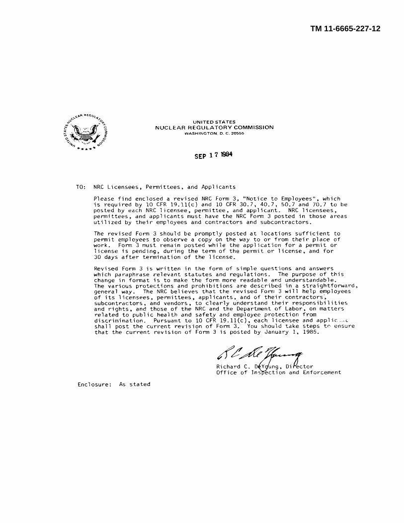
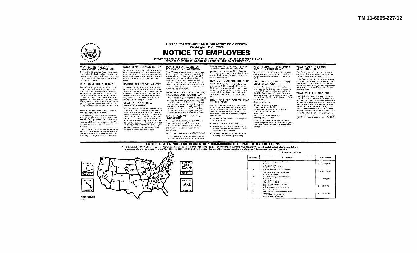
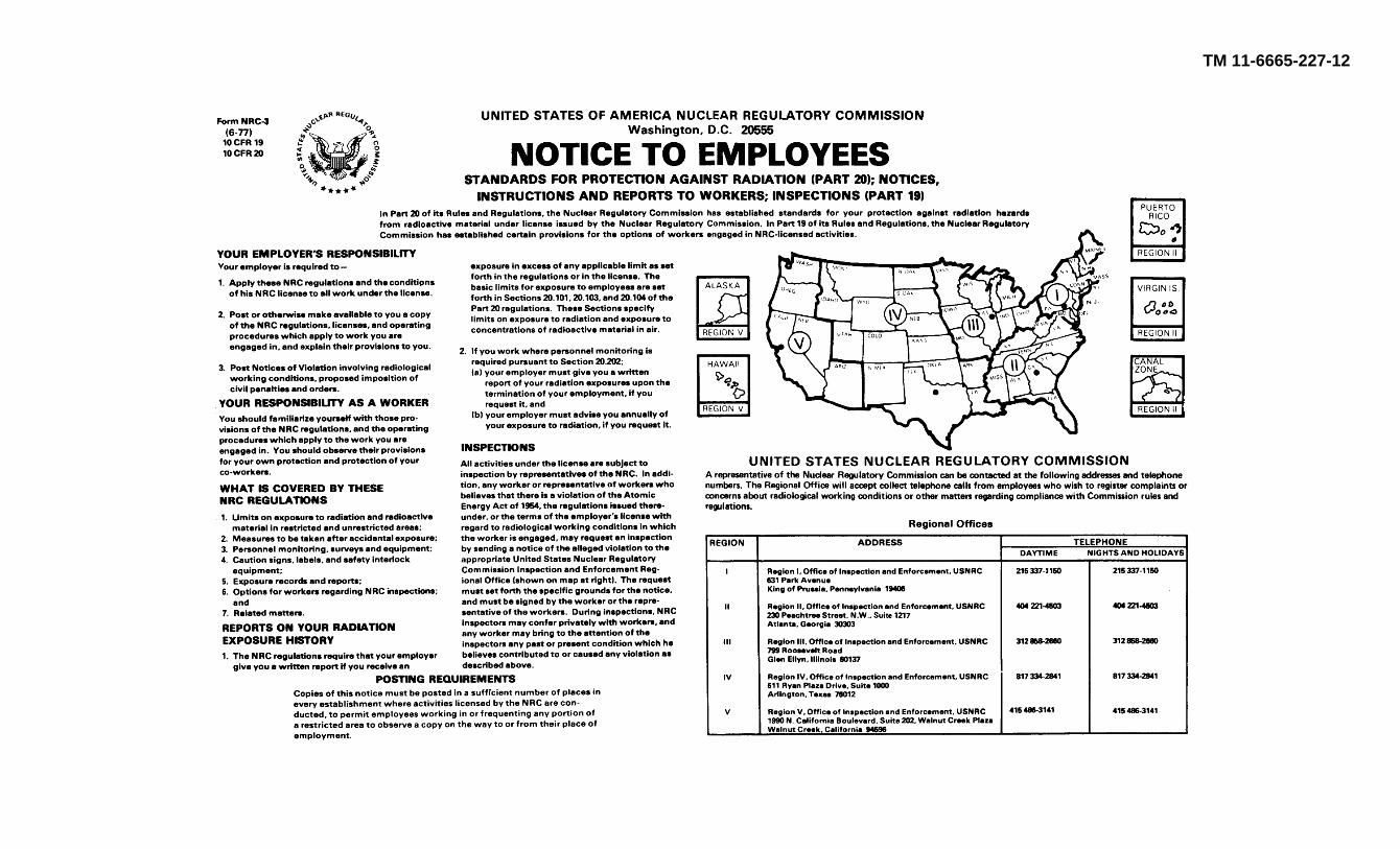
b. Notice to Employees. Form NRC-3, Notice toEmployees, contained in the back of this manual, may beremoved for posting wherever the AN/UDM-2 is usedand/or stored. The posting requirements are containedon the form.
c. NRC License. The NRC license for theAN/UDM-2 and documents relating to that license areheld by the US Army Communications-ElectronicsCommand Safety Office at Fort Monmouth, NJ.AN/UDM-2 users may request further information on
Change 5. 1-1
TM 11-6665-227-12
these documents by letter addressed to: Commander,US Army Communications-Electronics Command andFort Monmouth, ATTN: AMSEL-SF-MR, FortMonmouth, NJ 07703-5000. Requests for furtherinformation may also be made by phone by calling onAUTOVON 995-4427.
Change 5 1-2
TM 11-6665-227-12
Section II. DESCRIPTION AND DATA
1-7. Purpose and Use(fig. 1-1)
a. Purpose. Calibrator Set, Radiac ANIUDM-2(consisting of two main sections (b below)) provides thefacilities for checking the operational reliability andcalibration accuracy of various radiacmeters and radiacsets.
b. Use. Calibrator, Radiac TS34951UDM-2(discharge well assembly) is used to checkRadiacmeters IM-93(*)UD, IM-147/PD, and IM-9E/PD(dosimeters). Calibrator, Radiac TS-3494/UDM-2 (ratemeter assembly) is used to check Radiacmeter IM-174(*)1PD (radiacmeter), Radiac Set AN/PDR-27(*)(radiac set), Radiac Set ANIPDR40, and Aerial RadiacSystem AN/ADR-6.
1-8. Technical Characteristics
Type of radioactive isotope ineach source capsule ........... Strontium-Yttrium 90(Sr-Y90).Decay of isotope ............. 2.7 years half life.
Quantity of isotope:Discharge well assembly........... Three encapsulated sources
of 45 millicuries each. Oneencapsulated source of 30microcuries.
Ratemeter assembly One encapsulated source of 45millicuries.
Type of radiation emitted ........... Beta particles.
Maximum range of betaparticles in air ................ 30 feet.
Stopwatch indication Two indications: a minute hand for amaximum of 30 minutes and asecond hand for a maximumof 60 seconds.
1-9. Items Comprising an Operable Calibrator Set,Radiac AN/UDM-2(figs. 1-1, 1-2, and 143)
The components of the AN/UDM-2 that make up anoperable equipment are listed in table 1-1.
Table 1-1. Items Comprising an Operable Calibrator Set, Radiac ANIUDM-2
Dimensions (in )Wt
NSN Item Qty Height Depth Width (lb)666540410-1487 Calibrator, Radiac TS3494/UDM-2 1 5 12 12 10%6665-00-610-1496 Calibrator, Radiac TS3495/UDM-2 1 8 1/4 12 12 18V4Not available Adapter, ANIADR- 1 2 3/8 314 2Y4 %Not available Adapter probe, AN/PDR-60 1 5/8 5 .... 1/4Not available Stopwatch 1 .... .... .... ....Not available Spacer block 1 3 5/8 2 1/2 1 1/4 1/2Not available Collar, 1/2 inch 2 .... .... .... ....
1-10. Description of Calibrator Set, RadiacAN/UDM-2Calibrator Set, Radiac AN/UDM-2 (fig. 1-1) consists oftwo major assemblies, Calibrator, Radiac TS-3495/UDM-2 and Calibrator, Radiac TS-3494UDM-2, plus theAN/PDR640 adapter probe, and the AN/ADR-6 adapter.Each major assembly is housed in one-half of awaterproof, aluminum case.
A handle is provided on eachassembly to facilitate handling.
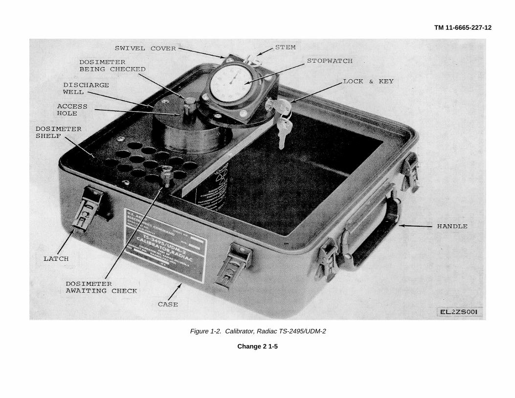
a. Calibrator, Radiac TS-3496/UDM-2 (fig. 1-2).The discharge well assembly consists of a dischargewell, a.
dosimeter shelf, and a stopwatch. The dosimeter shelfcontains 30 holes (to hold dosimeters to be tested) andthe discharge well. The discharge well contains fourSRY90 sources (one 30 microcurie source and three 45millicurie sources). The sources are arranged to radiateinto a central cavity. Two fields of radiation are providedwithin the discharge well; one field is provided by the 30-microcurie source (upper field), the other field is providedby the three 45 millicurie sources (lower field). The upperfield will cause Radiacmeter IM-9E/PD to discharge butwill have no effect on Radiacmeter IM-93(*)/PD or IM-147/PD. The lower field will cause the IM-93(*)/PD or theIM-147/PD to discharge and will also cause the IM-9E/PD to discharge within two seconds. An access holein the top of the discharge
Change 5 1-3
TM 11-6665-227-12
well provides access to the radiation fields in the cavity.The cavity is vertically placed in the discharge well. Thelower field of radiation is closed off from the access holeby a spring-loaded platform. This spring-loaded platformis opened when a dosimeter is inserted deep into theaccess hole. A spring-loaded swivel cover attached tothe top of the discharge well covers the access hole.The key-operated lock is mounted on the swivel.
cover to prevent accidental exposure of the access hole.The swivel cover is moved sideways to expose theaccess hole and will move back over the access holewhen the cover is released. A shipping lock is alsomounted on the swivel cover to prevent accidentalmovement of the cover during transit. The stopwatch,mounted on the swivel cover, times the period ofexposure for the dosimeter being checked.
1-4
TM 11-6665-227-12
Figure 1-2. Calibrator, Radiac TS-2495/UDM-2
Change 2 1-5
TM 11-6665-227-12
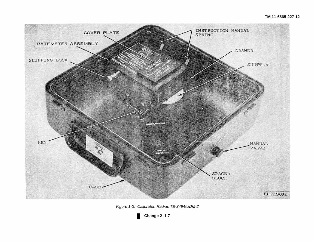
b. Calibrator, Radiac TS-3494/UDM-2 (fig. 1-3).The ratemeter assembly consists of a drawer and aspacer block. The drawer contains an excapsulated 45-millicurie Sr-Y90 source. Access to the radiation fieldcreated by the source is gained through a sliding drawerwithin the drawer. A shutter is located between thesliding drawer and the encapsulated source. The shutterhas two holes which provide radiation fields in thedetector equivalent to external gamma field of 100 rad/hrand 10 rad/hr. The shutter and sliding drawer are .
interconnected so that the shutter cannot expose thesource unless the drawer is fully closed. A key operatedlock is provided to prevent accidental movement of theshutter. The shutter can only be operated when the key-operated lock is open (unlocked) and the sliding draweris fully closed. A shipping lock mechanically locks thesliding drawer when the equipment is not in use. Thespacing block provides varying field intensities that areused to calibrate radiacmeter probes.
Change 5 1-6
TM 11-6665-227-12
Figure 1-3. Calibrator, Radiac TS-3494/UDM-2
Change 2 1-7
TM 11-6665-227-12
c. Miscellaneous. The AN/PDR-60 adapter probe(fig. 1-1) is furnished to enable checking the operationalcapability of the gamma range of Radiac Set AN/PDR-60. The AN/ADR-6 adapter is furnished to enablechecking Aerial Radiac System AN/ADR-6.
1-11. Precautions
The radiation hazard information must be understood by
all personnel before operating the AN/UDM-2.Hazardous radioactive materials are permanentlyinstalled in the major assemblies (fig. 1-1). Refer to theinside of the front cover and to TB 11-6665-227-12 forinformation on handling, storage, transportation,operation, and disposal of the radioactive materials.
1-8
TM 11-6665-227-12CHAPTER 2
INSTALLATION
2-1. Unpacking(fig. 2-1)
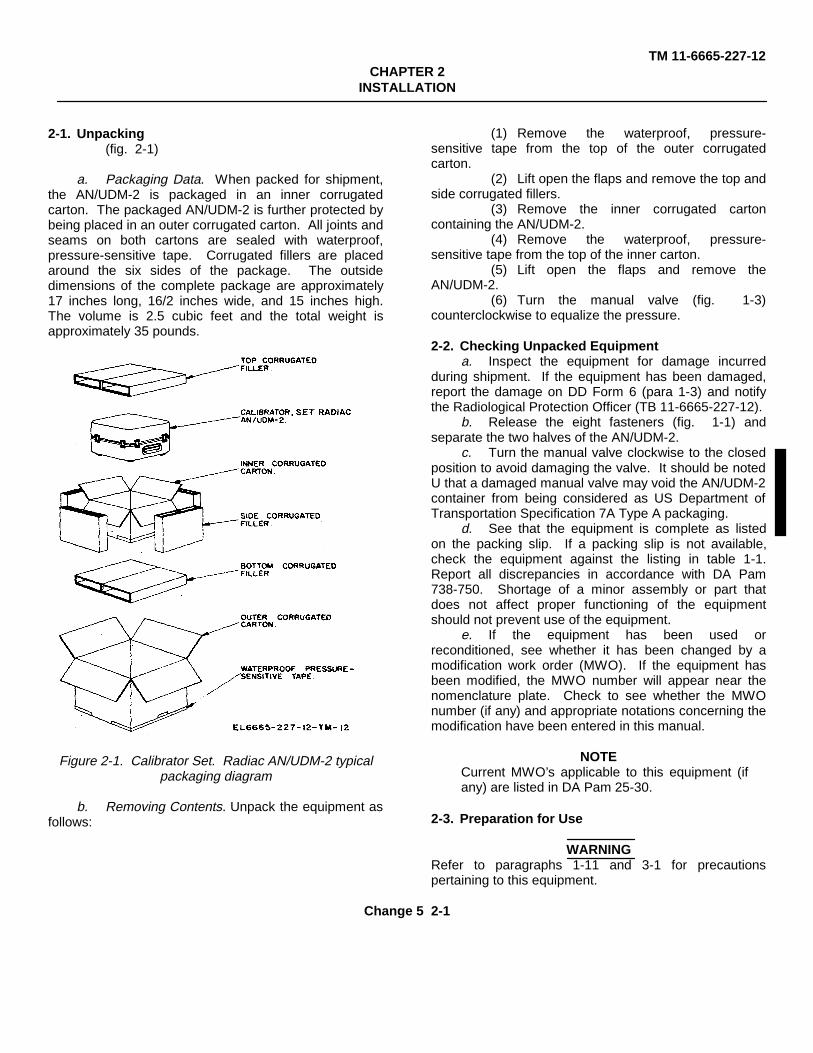
a. Packaging Data. When packed for shipment,the AN/UDM-2 is packaged in an inner corrugatedcarton. The packaged AN/UDM-2 is further protected bybeing placed in an outer corrugated carton. All joints andseams on both cartons are sealed with waterproof,pressure-sensitive tape. Corrugated fillers are placedaround the six sides of the package. The outsidedimensions of the complete package are approximately17 inches long, 16/2 inches wide, and 15 inches high.The volume is 2.5 cubic feet and the total weight isapproximately 35 pounds.
Figure 2-1. Calibrator Set. Radiac AN/UDM-2 typicalpackaging diagram
b. Removing Contents. Unpack the equipment asfollows:
(1) Remove the waterproof, pressure-sensitive tape from the top of the outer corrugatedcarton.
(2) Lift open the flaps and remove the top andside corrugated fillers.
(3) Remove the inner corrugated cartoncontaining the AN/UDM-2.
(4) Remove the waterproof, pressure-sensitive tape from the top of the inner carton.
(5) Lift open the flaps and remove theAN/UDM-2.
(6) Turn the manual valve (fig. 1-3)counterclockwise to equalize the pressure.
2-2. Checking Unpacked Equipmenta. Inspect the equipment for damage incurred
during shipment. If the equipment has been damaged,report the damage on DD Form 6 (para 1-3) and notifythe Radiological Protection Officer (TB 11-6665-227-12).
b. Release the eight fasteners (fig. 1-1) andseparate the two halves of the AN/UDM-2.
c. Turn the manual valve clockwise to the closedposition to avoid damaging the valve. It should be notedU that a damaged manual valve may void the AN/UDM-2container from being considered as US Department ofTransportation Specification 7A Type A packaging.
d. See that the equipment is complete as listedon the packing slip. If a packing slip is not available,check the equipment against the listing in table 1-1.Report all discrepancies in accordance with DA Pam738-750. Shortage of a minor assembly or part thatdoes not affect proper functioning of the equipmentshould not prevent use of the equipment.
e. If the equipment has been used orreconditioned, see whether it has been changed by amodification work order (MWO). If the equipment hasbeen modified, the MWO number will appear near thenomenclature plate. Check to see whether the MWOnumber (if any) and appropriate notations concerning themodification have been entered in this manual.
NOTECurrent MWO’s applicable to this equipment (ifany) are listed in DA Pam 25-30.
2-3. Preparation for Use
WARNINGRefer to paragraphs 1-11 and 3-1 for precautionspertaining to this equipment.
Change 5 2-1
TM 11-6665-227-12
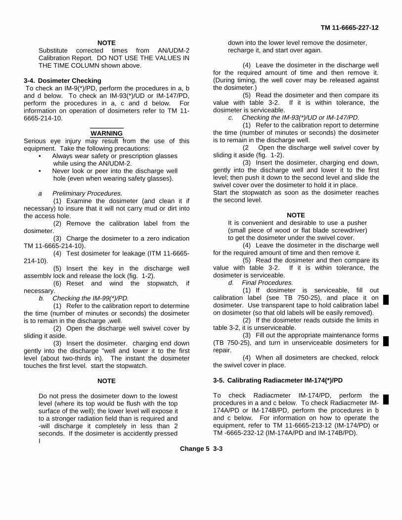
a. Release the shipping locks of both assemblies(fig. 1-2 and 1-3) by rotating the captive screwscounterclockwise. The shipping locks are spring-loaded,will spring outward when fully unscrewed, and willrelease the latches.
b. On the discharge well assembly (fig. 1-2),check the functioning of the stopwatch (table 3-1).
c. Insert the key in the lock, release the lock, androtate the swivel cover to expose the access hole.Release the cover; it shall move back into place andcover the access hole.
d. On the ratemeter assembly (fig. 1-3), check to besure that the spacer block is in place and that the drawerslides open.
e. Close the sliding drawer, insert the key in thelock, and release the lock. Check the operation of theshutter by rotating it.
NOTE
The sliding drawer must be closed completelybefore the shutter can be rotated.
Change 2 2-2
TM 11-6665-227-12
CHAPTER 3OPERATING INSTRUCTIONS
3-1. General
WARNING
Radioactive materials are used in this equipment. Readand understand all operational data and procedures inthis chapter before using the equipment. Becomethoroughly familiar with the contents of TB 11-6665-227-12. Never look directly into the access hole (fig. 1-2)when the swivel cover is swung open; do not poke sharppointed objects into the access hole. This equipment willbe used only under the direction of a RadiationProtection Officer.
Table 3-1 lists all controls and indicators used bythe operator. In addition, this chapter contains thefollowing: .
a. Procedures for checking Radiacmeters IM-9(*)/PD,IM-93(*)/UD, and IM-147/PD (para 3-4).
b. The procedures for calibrating RadiacmeterIM-174(*)/PD (para 3-5).
c. The procedures for calibrating Radiac SetAN/PDR-27(*) (para 3-6).
d. The procedures for calibrating Radiac SetAN/PDR-60 (para 3-7).
e. The procedures for calibrating Aerial RadiacSystem AN/ADR-6 will be given in paragraph 3-8 whenthey become available.
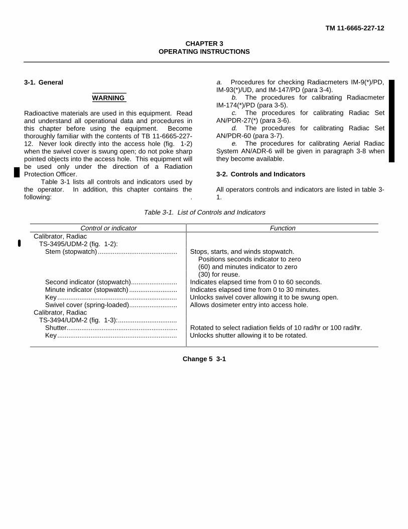
3-2. Controls and Indicators
All operators controls and indicators are listed in table 3-1.
Table 3-1. List of Controls and Indicators
Control or indicator FunctionCalibrator, Radiac
TS-3495/UDM-2 (fig. 1-2):Stem (stopwatch) ........................................... Stops, starts, and winds stopwatch.
Positions seconds indicator to zero(60) and minutes indicator to zero(30) for reuse.
Second indicator (stopwatch)......................... Indicates elapsed time from 0 to 60 seconds.Minute indicator (stopwatch) .......................... Indicates elapsed time from 0 to 30 minutes.Key................................................................. Unlocks swivel cover allowing it to be swung open.Swivel cover (spring-loaded).......................... Allows dosimeter entry into access hole.
Calibrator, RadiacTS-3494/UDM-2 (fig. 1-3):................................
Shutter............................................................ Rotated to select radiation fields of 10 rad/hr or 100 rad/hr.Key................................................................. Unlocks shutter allowing it to be rotated.
Change 5 3-1
TM 11-6665-227-12
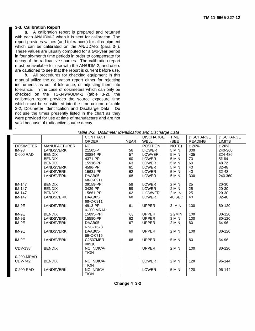
3-3. Calibration Reporta. A calibration report is prepared and returned
with each AN/UDM-2 when it is sent for calibration. Thereport provides values (and tolerances) for all equipmentwhich can be calibrated on the AN/UDM-2 (para 3-I).These values are usually computed for a two-year periodin four six-month time periods in order to compensate fordecay of the radioactive sources. The calibration reportmust be available for use with the AN/UDM-2, and usersare cautioned to see that the report is current before use.
b. All procedures for checking equipment in thismanual utilize the calibration report either for rejectinginstruments as out of tolerance, or adjusting them intotolerance. In the case of dosimeters which can only bechecked on the TS-3494/UDM-2 (table 3-2), thecalibration report provides the source exposure timewhich must be substituted into the time column of table3-2, Dosimeter Identification and Discharge Data. Donot use the times presently listed in the chart as theywere provided for use at time of manufacture and are notvalid because of radioactive source decay.
Table 3-2. Dosimeter Identification and Discharge DataCONTRACTORDER YEAR
DISCHARGEWELL
TIME(SEE
DISCHARGEREADING
DISCHARGELIMITS
DOSIMETER MANUFACTURER NO. POSITION NOTE) ± 20% ± 20%IM-93 LANDSVERK 21505-P 56 LIOWER 5 MIN 300 240-3600-600 RAD BENDIX 30884-PP 57 LOWVER 5 MIN 405 324-486
BENDIX 4371-PP 60 LOWER 5 MIN 70 5fi-84BENDIX 15916-PP 63 LOWER 5 MIN 60 48 72LANDSVERK 4596-PP 61 LOWER 5 MIN 40 32-48LANDSVERK 15631-PP 62 LOWER 5 MIN 40 32-48LANDSVERK DAAB05- 68 LOWER 5 MIN 300 240 360
68-C-0911IM-147 BENDIX 39159-PP 58 LOWER 2 MIN 25 20-30IM-147 BENDIX 3439-PP 59 LOWER 2 MIN 25 20-30IM-147 BENDIX 15861-PP 62 ILOWVER 2 MIIN 25 20-30IM-147 LANDSCERK DAAB05- 68 LOWER 40 SEC 40 32-48
68-C-0911IM-9E LANDSVERK 4913-PP 61 UPPER 3 .MIN 100 80-120
0-200 MRADIM-9E BENDIX 15895-PP '63 UPPER 2 2MIN 100 80-120IM-9E LANDSVERK 15580-PP 62 UPPER 3 MIN 100 80-120IM-9E LANDSVERK DAAB05- 67 UPPER 2 MIN 80 64-96
67-C-1678IM-9E LANDSVERK DAAB05- 69 UPPER 2 MIN 100 80-120
69-C-0716IM-9F LANDSVERK C2537MER 68 UPPER 5 MIN 80 64-96
00910CDV-138 BENDIX NO INDICA- UPPER 2 MIN 100 80-120
TION0-200-MRADCDV-742 BENDIX NO INDICA- LOWER 2 MIN 120 96-144
TION0-200-RAD LANDSVERK NO INDICA- LOWER 5 MIN 120 96-144
TION
Change 4 3-2
TM 11-6665-227-12
NOTESubstitute corrected times from AN/UDM-2Calibration Report. DO NOT USE THE VALUES INTHE TIME COLUMN shown above.
3-4. Dosimeter Checking To check an IM-9(*)/PD, perform the procedures in a, band d below. To check an IM-93(*)/UD or IM-147/PD,perform the procedures in a, c and d below. Forinformation on operation of dosimeters refer to TM 11-6665-214-10.
WARNINGSerious eye injury may result from the use of thisequipment. Take the following precautions:
• Always wear safety or prescription glasseswhile using the AN/UDM-2.
• Never look or peer into the discharge wellhole (even when wearing safety glasses).
a Preliminary Procedures.(1) Examine the dosimeter (and clean it if
necessary) to insure that it will not carry mud or dirt intothe access hole.
(2) Remove the calibration label from thedosimeter.
(3) Charge the dosimeter to a zero indicationTM 11-6665-214-10).
(4) Test dosimeter for leakage (ITM 11-6665-214-10).
(5) Insert the key in the discharge wellassemblv lock and release the lock (fig. 1-2).
(6) Reset and wind the stopwatch, ifnecessary.
b. Checking the IM-99(*)/PD.(1) Refer to the calibration report to determine
the time (number of minutes or seconds) the dosimeteris to remain in the discharge ,well.
(2) Open the discharge well swivel cover bysliding it aside.
(3) Insert the dosimeter. charging end downgently into the discharge "well and lower it to the firstlevel (about two-thirds in). The instant the dosimetertouches the first level. start the stopwatch.
NOTE
Do not press the dosimeter down to the lowestlevel (where its top would be flush with the topsurface of the well); the lower level will expose itto a stronger radiation field than is required and-will discharge it completely in less than 2seconds. If the dosimeter is accidently pressedI
down into the lower level remove the dosimeter,recharge it, and start over again.
(4) Leave the dosimeter in the discharge wellfor the required amount of time and then remove it.(During timing, the well cover may be released againstthe dosimeter.)
(5) Read the dosimeter and then compare itsvalue with table 3-2. If it is within tolerance, thedosimeter is serviceable.
c. Checking the IM-93(*)/UD or IM-147/PD.(1) Refer to the calibration report to determine
the time (number of minutes or seconds) the dosimeteris to remain in the discharge well.
(2 Open the discharge well swivel cover bysliding it aside (fig. 1-2).
(3) Insert the dosimeter, charging end down,gently into the discharge well and lower it to the firstlevel; then push it down to the second level and slide theswivel cover over the dosimeter to hold it in place.Start the stopwatch as soon as the dosimeter reachesthe second level.
NOTEIt is convenient and desirable to use a pusher(small piece of wood or flat blade screwdriver)to get the dosimeter under the swivel cover.
(4) Leave the dosimeter in the discharge wellfor the required amount of time and then remove it.
(5) Read the dosimeter and then compare itsvalue with table 3-2. If it is within tolerance, thedosimeter is serviceable.
d. Final Procedures.(1) If dosimeter is serviceable, fill out
calibration label (see TB 750-25), and place it ondosimeter. Use transparent tape to hold calibration labelon dosimeter (so that old labels will be easily removed).
(2) If the dosimeter reads outside the limits intable 3-2, it is unserviceable.
(3) Fill out the appropriate maintenance forms(TB 750-25), and turn in unserviceable dosimeters forrepair.
(4) When all dosimeters are checked, relockthe swivel cover in place.
3-5. Calibrating Radiacmeter IM-174(*)/PD
To check Radiacmeter IM-174/PD, perform theprocedures in a and c below. To check Radiacmeter IM-174A/PD or IM-174B/PD, perform the procedures in band c below. For information on how to operate theequipment, refer to TM 11-6665-213-12 (IM-174/PD) orTM -6665-232-12 (IM-174A/PD and IM-174B/PD).
Change 5 3-3
TM 11-6665-227-12
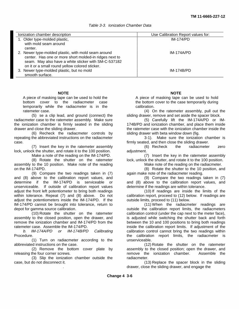
NOTEThere are three different types of ionization chambersused in the IM-174(*)/PD; an older type and two newertypes. The older type was originally procured for the IM-174/PD, and the newer types for the IM-174A/PD andIM-174B/PD. These ionization chambers sometimes getinterchanged and cause problems when checking on theAN/UDM-2 because the older type ionization chamberreads higher than the newer types. When using theAN/UDM-2 to calibrate the IM-174(*)/PD, refer to thedate in table 3-3 to select the values from the calibrationreport for calibrating older or newer type ionizationchambers.
a. IM-174/PD Calibrating Procedure.(1) Turn the radiacmeter on according to the
abbreviated instructions on the case.(2) Remove the bottom cover plate by
releasing the four screws. Remove, but do notdisconnect, the ionization chamber, and set it outside theradiacmeter case.
(3) On the ratemeter assembly, release theshipping lock (fig. 1-3), pull out the sliding drawer,remove and set aside the spacer block.
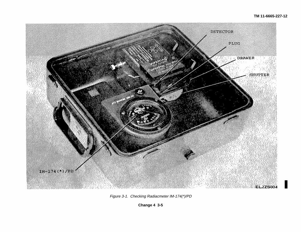
(4) Carefully lift the IM-174/PD and ionizationchamber, and place them inside the ratemeter case withthe ionization chamber inside the sliding drawer with thebeta window down (fig. 3-1).
Change 4 3-4
TM 11-6665-227-12
Figure 3-1. Checking Radiacmeter IM-174(*)/PD
Change 4 3-5
TM 11-6665-227-12
Table 3-3. Ionization Chamber Data
Ionization chamber description Use Calibration Report values for:1. Older type-molded plastic, IM-174/PD
with mold seam aroundcenter.
2. Newer type-molded plastic, with mold seam around IM-174A/PDcenter. Has one or more short molded-in ridges next toseam. May also have a white sticker with SM-C-537182on it or a small round yellow colored sticker.
3. Newer type-molded plastic, but no mold IM-174B/PDsmooth surface.
NOTEA piece of masking tape can be used to hold thebottom cover to the radiacmeter casetemporarily while the radiacmeter is in theratemeter case.
(5) se a clip lead, and ground (connect) theradiacmeter case to the ratemeter assembly. Make surethe ionization chamber is firmly seated in the slidingdrawer and close the sliding drawer.
(6) Recheck the radiacmeter controls byrepeating the abbreviated instructions on the radiacmetercase.
(7) Insert the key in the ratemeter assemblylock, unlock the shutter, and rotate it to the 100 position.
Make a note of the reading on the IM-174/PD.(8) Rotate the shutter on the ratemeter
assembly to the 10 position. Make note of the readingon the IM-174/PD.
(9) Compare the two readings taken in (7)and (8) above to the calibration report values, anddetermine if the IM-174/PD is serviceable orunserviceable. If outside of calibration report valuesadjust the front left potentiometer to bring both readingswithin tolerance. Repeat (7) and (8) above. Do notadjust the potentiometers inside the IM-174/PD. If theIM-174/PD cannot be brought into tolerance, return todepot for gamma source calibration.
(10) Rotate the shutter on the ratemeterassembly to the closed position, open the drawer, andremove the ionization chamber and IM-174/PD from theratemeter case. Assemble the IM-174/PD.
b. IM-174A/PD or IM-174B/PD CalibratingProcedure.
(1) Turn on radiacmeter according to theabbreviated instructions on the case.
(2) Remove the bottom cover plate byreleasing the four corner screws.
(3) Slip the ionization chamber outside thecase, but do not disconnect it.
.
NOTEA piece of masking tape can be used to holdthe bottom cover to the case temporarily duringcalibration.
(4) On the ratemeter assembly, pull out thesliding drawer, remove and set aside the spacer block.
(5) Carefully lift the IM-174A/PD or IM-174B/PD and ionization chamber, and place them insidethe ratemeter case with the ionization chamber inside thesliding drawer with beta window down (fig.
3-1). Make sure the ionization chamber isfirmly seated, and then close the sliding drawer.
(6) Recheck the radiacmeter zeroadjustment.
(7) Insert the key in the ratemeter assemblylock, unlock the shutter, and rotate it to the 100 position.
Make note of the reading on the radiacmeter.(8) Rotate the shutter to the 10 position, and
again make note of the radiacmeter reading.(9) Compare the two readings taken in (7)
and (8) above to the calibration report values, anddetermine if the readings are within tolerance.
(10) If readings are inside the limits of thecalibration report, proceed to (12) below. If readings areoutside limits, proceed to (11) below.
(11) When the radiacmeter readings areoutside the calibration report limits, the radiacmeterscalibration control (under the cap next to the meter face),is adjusted while switching the shutter back and forthbetween the 10 and 100 positions to bring both readingsinside the calibration report limits. If adjustment of thecalibration control cannot bring the two readings withinthe calibration report limits, the radiacmeter isunserviceable.
(12) Rotate the shutter on the ratemeterassembly to the closed position; open the drawer, andremove the ionization chamber. Assemble theradiacmeter.
(13) Replace the spacer block in the slidingdrawer, close the sliding drawer, and engage the
Change 4 3-6
TM 11-6665-227-12
shipping lock. Lock the ratemeter assembly lock andremove the key.
c. Final Procedures.(1) ON IM-174(*)/PD which are serviceable,
fill out a calibration label and place it on the radiacmeter(see TB 750-25-1).
(2) For IM-174(a)/PD which are notserviceable, annotate DA Form 2417 (see TB 750-25-1).Repair and calibrate radiacmeter or turn item in toorganization with repair capability. See a(9) aboveregarding unserviceable IM-174/PD’s
Change 4 3-7/(3-8 Blank)
TM 11-6665-227-12
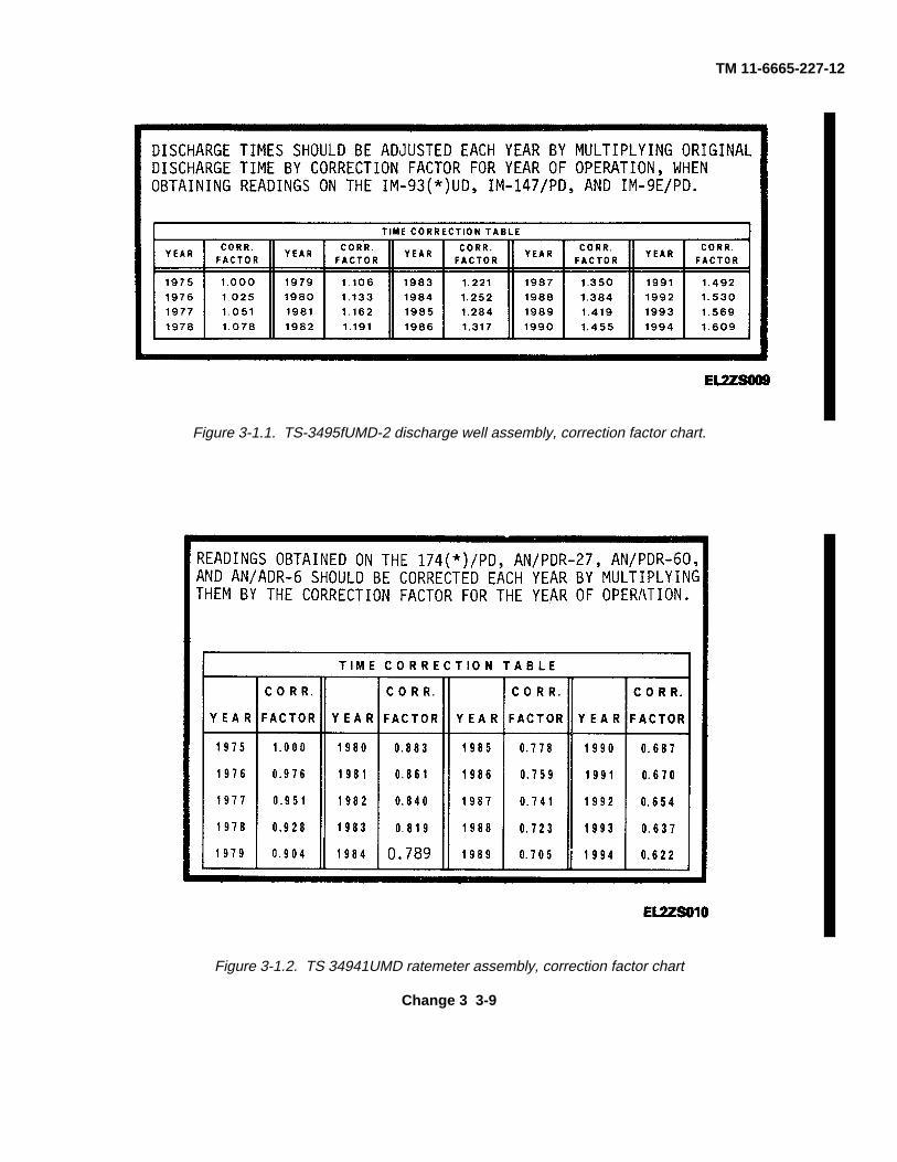
Figure 3-1.1. TS-3495fUMD-2 discharge well assembly, correction factor chart.
Figure 3-1.2. TS 34941UMD ratemeter assembly, correction factor chart
Change 3 3-9
TM 11-6665-227-12
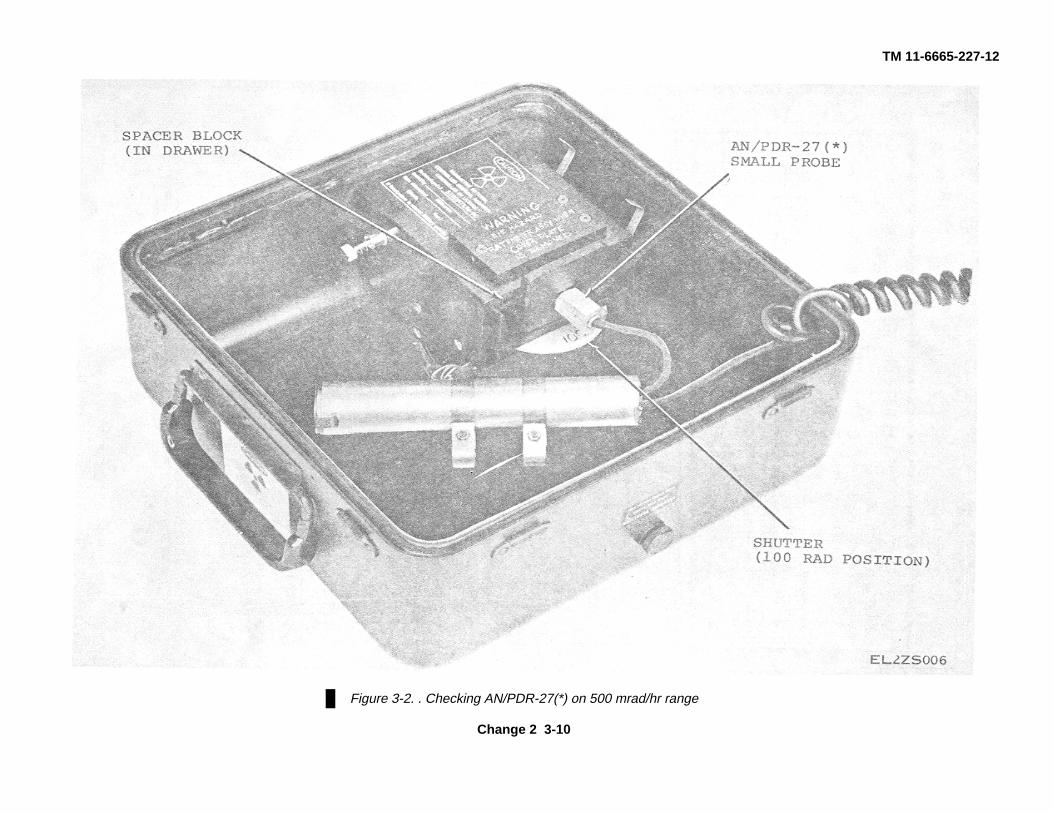
Figure 3-2. . Checking AN/PDR-27(*) on 500 mrad/hr range
Change 2 3-10
TM 11-6665-227-12
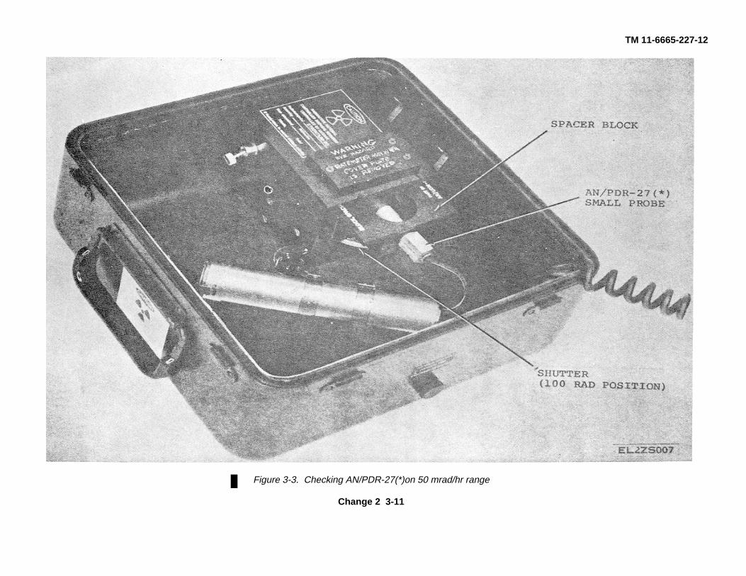
Figure 3-3. Checking AN/PDR-27(*)on 50 mrad/hr range
Change 2 3-11
TM 11-6665-227-12
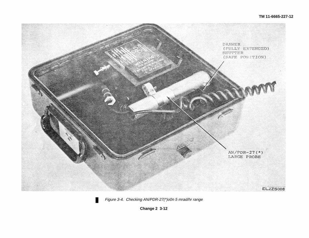
Figure 3-4. Checking AN/PDR-27(*)o0n 5 mrad/hr range
Change 2 3-12
TM 11-6665-227-12
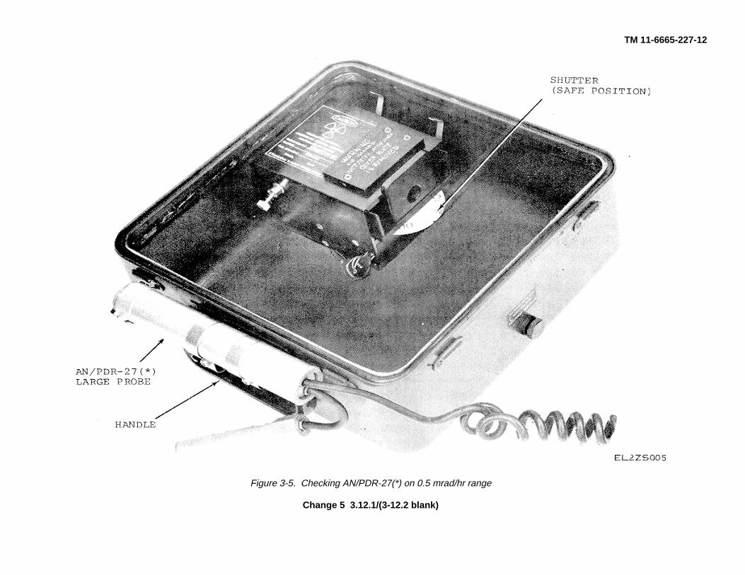
Figure 3-5. Checking AN/PDR-27(*) on 0.5 mrad/hr range
Change 5 3.12.1/(3-12.2 blank)
TM 11-6665-227-12
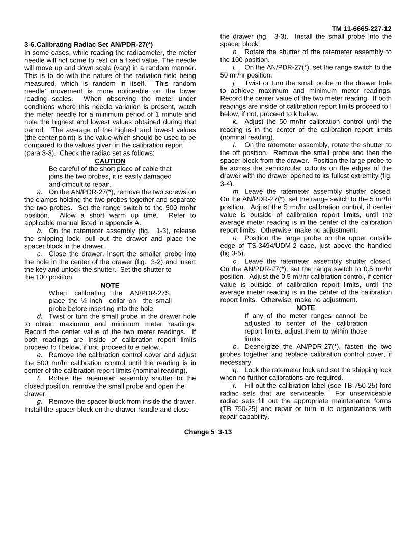
3-6.Calibrating Radiac Set AN/PDR-27(*)In some cases, while reading the radiacmeter, the meterneedle will not come to rest on a fixed value. The needlewill move up and down scale (vary) in a random manner.This is to do with the nature of the radiation field beingmeasured, which is random in itself. This randomneedle’ movement is more noticeable on the lowerreading scales. When observing the meter underconditions where this needle variation is present, watchthe meter needle for a minimum period of 1 minute andnote the highest and lowest values obtained during thatperiod. The average of the highest and lowest values(the center point) is the value which should be used to becompared to the values given in the calibration report(para 3-3). Check the radiac set as follows:
CAUTIONBe careful of the short piece of cable thatjoins the two probes, it is easily damagedand difficult to repair.
a. On the AN/PDR-27(*), remove the two screws onthe clamps holding the two probes together and separatethe two probes. Set the range switch to the 500 mr/hrposition. Allow a short warm up time. Refer toapplicable manual listed in appendix A.
b. On the ratemeter assembly (fig. 1-3), releasethe shipping lock, pull out the drawer and place thespacer block in the drawer.
c. Close the drawer, insert the smaller probe intothe hole in the center of the drawer (fig. 3-2) and insertthe key and unlock the shutter. Set the shutter tothe 100 position.
NOTEWhen calibrating the AN/PDR-27S,place the ½ inch collar on the smallprobe before inserting into the hole.
d. Twist or turn the small probe in the drawer holeto obtain maximum and minimum meter readings.Record the center value of the two meter readings. Ifboth readings are inside of calibration report limitsproceed to f below, if not, proceed to e below.
e. Remove the calibration control cover and adjustthe 500 mr/hr calibration control until the reading is incenter of the calibration report limits (nominal reading).
f. Rotate the ratemeter assembly shutter to theclosed position, remove the small probe and open thedrawer.
g. Remove the spacer block from inside the drawer.Install the spacer block on the drawer handle and close
the drawer (fig. 3-3). Install the small probe into thespacer block.
h. Rotate the shutter of the ratemeter assembly tothe 100 position.
i. On the AN/PDR-27(*), set the range switch to the50 mr/hr position.
j. Twist or turn the small probe in the drawer holeto achieve maximum and minimum meter readings.Record the center value of the two meter reading. If bothreadings are inside of calibration report limits proceed to Ibelow, if not, proceed to k below.
k. Adjust the 50 mr/hr calibration control until thereading is in the center of the calibration report limits(nominal reading).
I. On the ratemeter assembly, rotate the shutter tothe off position. Remove the small probe and then thespacer block from the drawer. Position the large probe tolie across the semicircular cutouts on the edges of thedrawer with the drawer opened to its fullest extremity (fig.3-4).
m. Leave the ratemeter assembly shutter closed.On the AN/PDR-27(*), set the range switch to the 5 mr/hrposition. Adjust the 5 mr/hr calibration control, if centervalue is outside of calibration report limits, until theaverage meter reading is in the center of the calibrationreport limits. Otherwise, make no adjustment.
n. Position the large probe on the upper outsideedge of TS-3494/UDM-2 case, just above the handled(fig 3-5).
o. Leave the ratemeter assembly shutter closed.On the AN/PDR-27(*), set the range switch to 0.5 mr/hrposition. Adjust the 0.5 mr/hr calibration control, if centervalue is outside of calibration report limits, until theaverage meter reading is in the center of the calibrationreport limits. Otherwise, make no adjustment.
NOTEIf any of the meter ranges cannot beadjusted to center of the calibrationreport limits, adjust them to within thoselimits.
p. Deenergize the AN/PDR-27(*), fasten the twoprobes together and replace calibration control cover, ifnecessary.
q. Lock the ratemeter lock and set the shipping lockwhen no further calibrations are required.
r. Fill out the calibration label (see TB 750-25) fordradiac sets that are serviceable. For unserviceableradiac sets fill out the appropriate maintenance forms(TB 750-25) and repair or turn in to organizations withrepair capability.
Change 5 3-13
TM 11-6665-227-12
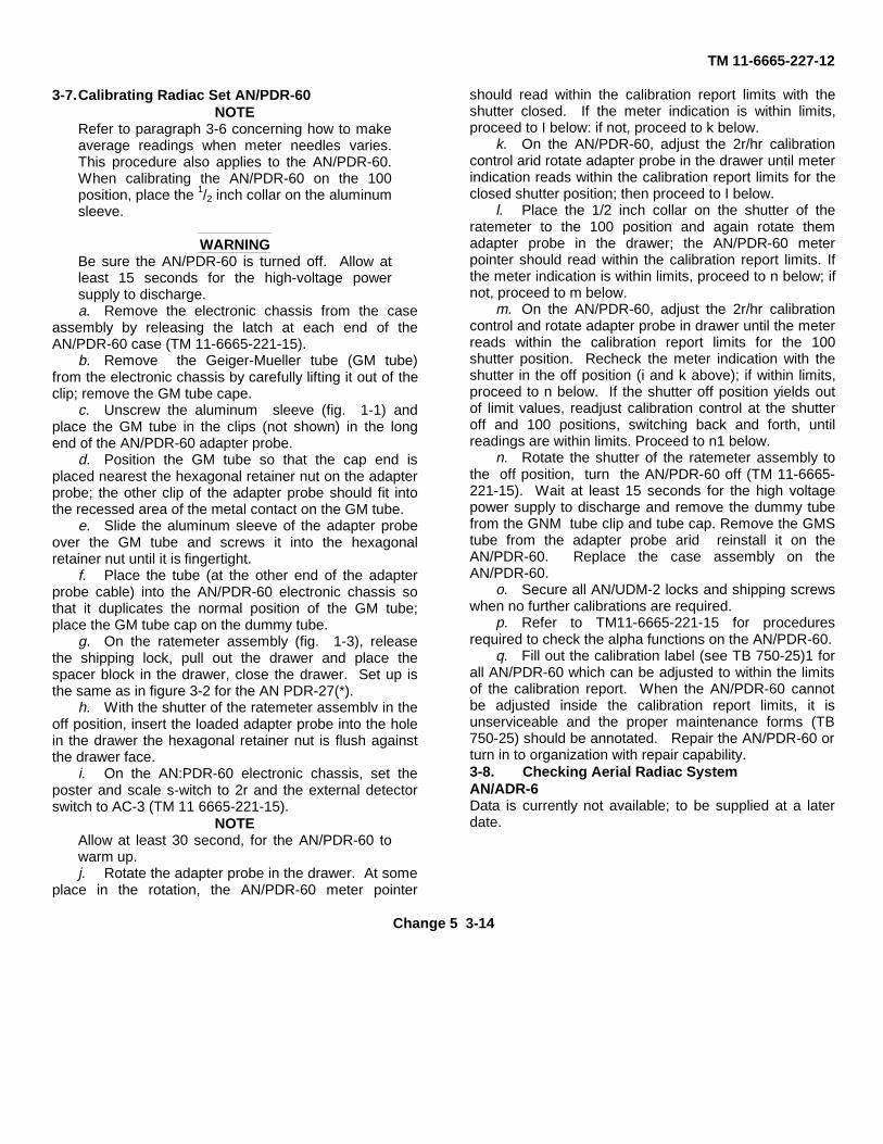
3-7.Calibrating Radiac Set AN/PDR-60NOTE
Refer to paragraph 3-6 concerning how to makeaverage readings when meter needles varies.This procedure also applies to the AN/PDR-60.When calibrating the AN/PDR-60 on the 100position, place the 1/2 inch collar on the aluminumsleeve.
WARNINGBe sure the AN/PDR-60 is turned off. Allow atleast 15 seconds for the high-voltage powersupply to discharge.a. Remove the electronic chassis from the case
assembly by releasing the latch at each end of theAN/PDR-60 case (TM 11-6665-221-15).
b. Remove the Geiger-Mueller tube (GM tube)from the electronic chassis by carefully lifting it out of theclip; remove the GM tube cape.
c. Unscrew the aluminum sleeve (fig. 1-1) andplace the GM tube in the clips (not shown) in the longend of the AN/PDR-60 adapter probe.
d. Position the GM tube so that the cap end isplaced nearest the hexagonal retainer nut on the adapterprobe; the other clip of the adapter probe should fit intothe recessed area of the metal contact on the GM tube.
e. Slide the aluminum sleeve of the adapter probeover the GM tube and screws it into the hexagonalretainer nut until it is fingertight.
f. Place the tube (at the other end of the adapterprobe cable) into the AN/PDR-60 electronic chassis sothat it duplicates the normal position of the GM tube;place the GM tube cap on the dummy tube.
g. On the ratemeter assembly (fig. 1-3), releasethe shipping lock, pull out the drawer and place thespacer block in the drawer, close the drawer. Set up isthe same as in figure 3-2 for the AN PDR-27(*).
h. With the shutter of the ratemeter assemblv in theoff position, insert the loaded adapter probe into the holein the drawer the hexagonal retainer nut is flush againstthe drawer face.
i. On the AN:PDR-60 electronic chassis, set theposter and scale s-witch to 2r and the external detectorswitch to AC-3 (TM 11 6665-221-15).
NOTEAllow at least 30 second, for the AN/PDR-60 towarm up.j. Rotate the adapter probe in the drawer. At some
place in the rotation, the AN/PDR-60 meter pointer
should read within the calibration report limits with theshutter closed. If the meter indication is within limits,proceed to I below: if not, proceed to k below.
k. On the AN/PDR-60, adjust the 2r/hr calibrationcontrol arid rotate adapter probe in the drawer until meterindication reads within the calibration report limits for theclosed shutter position; then proceed to I below.
l. Place the 1/2 inch collar on the shutter of theratemeter to the 100 position and again rotate themadapter probe in the drawer; the AN/PDR-60 meterpointer should read within the calibration report limits. Ifthe meter indication is within limits, proceed to n below; ifnot, proceed to m below.
m. On the AN/PDR-60, adjust the 2r/hr calibrationcontrol and rotate adapter probe in drawer until the meterreads within the calibration report limits for the 100shutter position. Recheck the meter indication with theshutter in the off position (i and k above); if within limits,proceed to n below. If the shutter off position yields outof limit values, readjust calibration control at the shutteroff and 100 positions, switching back and forth, untilreadings are within limits. Proceed to n1 below.
n. Rotate the shutter of the ratemeter assembly tothe off position, turn the AN/PDR-60 off (TM 11-6665-221-15). Wait at least 15 seconds for the high voltagepower supply to discharge and remove the dummy tubefrom the GNM tube clip and tube cap. Remove the GMStube from the adapter probe arid reinstall it on theAN/PDR-60. Replace the case assembly on theAN/PDR-60.
o. Secure all AN/UDM-2 locks and shipping screwswhen no further calibrations are required.
p. Refer to TM11-6665-221-15 for proceduresrequired to check the alpha functions on the AN/PDR-60.
q. Fill out the calibration label (see TB 750-25)1 forall AN/PDR-60 which can be adjusted to within the limitsof the calibration report. When the AN/PDR-60 cannotbe adjusted inside the calibration report limits, it isunserviceable and the proper maintenance forms (TB750-25) should be annotated. Repair the AN/PDR-60 orturn in to organization with repair capability.3-8. Checking Aerial Radiac SystemAN/ADR-6Data is currently not available; to be supplied at a laterdate.
Change 5 3-14
TM 11-6665-227-12
CHAPTER 4MAINTENANCE INSTRUCTIONS
4-1.Scope of Maintenance The maintenance dutiesassigned to the operator and organizational repairman ofthe AN/UDM-2 are listed below together with a referenceto the paragraphs covering the specific maintenancefunction. The AN/UDM-2, when the two halves aresealed, is waterproof. The swivel cover on the dischargewell assembly restricts entry of foreign matter to theaccess hole, but is not waterproof. This cover may beremoved to clean the pivot pin assembly when required.
WARNINGNEVER disassemble the cavities of thedischarge well assembly or the ratemeterassembly. This procedure is dangerous andmust be performed only by higher categorymaintenance personnel with adequate facilitiesmeeting all requirements of TB 11-6665-227-12.a. Operator preventive maintenance checks and
services (table 4-1).b. Organizational preventive maintenance checks
and services (table 4-2).c. Cleaning and touchup painting (para 4-5).d. Troubleshooting (para 4-).e. Wipe test (TB 11-6665-227-12).
4-2.Tools and Equipment Required No special tools ortest equipment other than those listed in appendix C arerequired. The materials required for maintenance arelisted below.
a. Trichlorotrifluoroethane cleaning compound(NSN 6850-00-105-3084).
b. Cleaning cloth (NSN 8305-00-245-4509). c. Cotton swabs (NSN 6515-00-303-8250). d. Sandpaper (No. 000).e. Petroleum jelly or light machine oil.
4-3.Preventive Maintenance To insure that theAN/UDM-2 is always ready for operation, it must beinspected systematically so that defects may bediscovered and corrected before they result in seriousdamage or failure. Defects discovered
during operation of the unit will be noted (TB 11-6665-227-12) for future correction to be made as soon asoperation has ceased. Stop operation immediately if adeficiency is noted during operation which would damagethe equipment or harm personnel. Record alldeficiencies together with the corrective action taken inaccordance with the requirements of TB 11-6665-227-12and DA Pam 738-750.4-4.Preventive Maintenance Checks and Services(PMCS)
a. General. Preventive maintenance checks andservices defines procedures to be performed at specificintervals and under certain conditions. Routinemaintenance such as dusting and cleaning, checking forloose nuts and bolts, etc., are not listed as PMCSprocedures. These are things that should be done on aroutine basis.
NOTEBefore performing PMCS observe all CAUTIONSand WARNINGS in this manual.b. Operator/Crew PMCS, Table 4-1.
(1) Item number column. Use the number in thiscolumn on DA Form 2404, Equipment Inspection andMaintenance Worksheet when recording results ofPMCS.
(2) Interval column. A dot () in the B, D, or Acolumn indicates that the check is to be made eitherbefore, during or after operation.
(3) For readiness reporting, equipment is notready/available if: column. This column contains thestandards which will cause the equipment to be reportednot ready or not available because it cannot perform itsprimary mission.
c. Organizational PMCS Monthly Schedule, Table4-2. Use the number in the Item Number Column on DAForm 2404, Equipment Inspection and MaintenanceWorksheet when recording results of PMCS.
Change 4 4-1
TM 11-6665-227-12
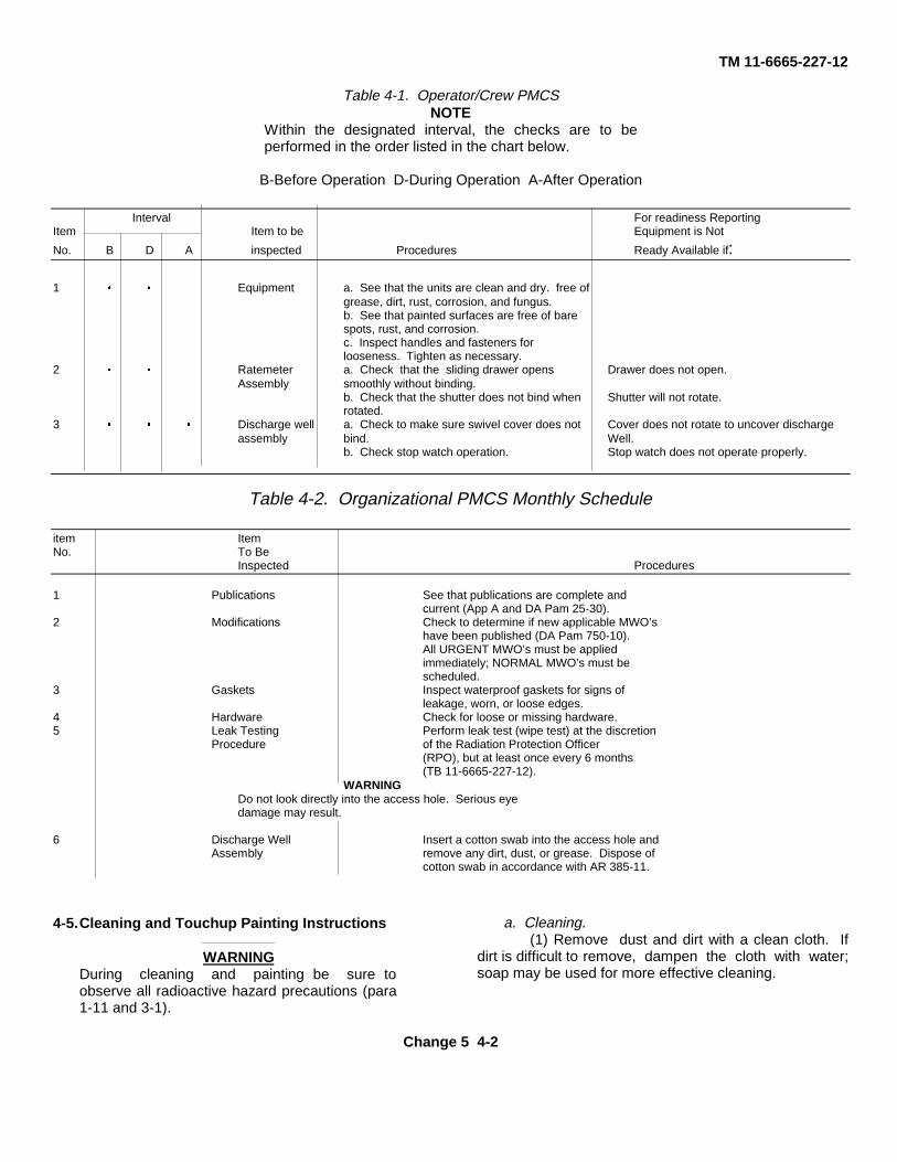
Table 4-1. Operator/Crew PMCSNOTE
Within the designated interval, the checks are to beperformed in the order listed in the chart below.
B-Before Operation D-During Operation A-After Operation
Interval For readiness ReportingItem Item to be Equipment is Not
No. B D A inspected Procedures Ready Available if:
1 á á Equipment a. See that the units are clean and dry. free ofgrease, dirt, rust, corrosion, and fungus.b. See that painted surfaces are free of barespots, rust, and corrosion.c. Inspect handles and fasteners forlooseness. Tighten as necessary.
2 á á Ratemeter a. Check that the sliding drawer opens Drawer does not open.Assembly smoothly without binding.
b. Check that the shutter does not bind when Shutter will not rotate.rotated.
3 á á á Discharge well a. Check to make sure swivel cover does not Cover does not rotate to uncover dischargeassembly bind. Well.
b. Check stop watch operation. Stop watch does not operate properly.
Table 4-2. Organizational PMCS Monthly Schedule
item ItemNo. To Be
Inspected Procedures
1 Publications See that publications are complete andcurrent (App A and DA Pam 25-30).
2 Modifications Check to determine if new applicable MWO’shave been published (DA Pam 750-10).All URGENT MWO’s must be appliedimmediately; NORMAL MWO’s must bescheduled.
3 Gaskets Inspect waterproof gaskets for signs ofleakage, worn, or loose edges.
4 Hardware Check for loose or missing hardware.5 Leak Testing Perform leak test (wipe test) at the discretion
Procedure of the Radiation Protection Officer(RPO), but at least once every 6 months(TB 11-6665-227-12).
WARNINGDo not look directly into the access hole. Serious eyedamage may result.
6 Discharge Well Insert a cotton swab into the access hole andAssembly remove any dirt, dust, or grease. Dispose of
cotton swab in accordance with AR 385-11.
4-5.Cleaning and Touchup Painting Instructions
WARNINGDuring cleaning and painting be sure toobserve all radioactive hazard precautions (para1-11 and 3-1).
a. Cleaning.(1) Remove dust and dirt with a clean cloth. If
dirt is difficult to remove, dampen the cloth with water;soap may be used for more effective cleaning.
Change 5 4-2
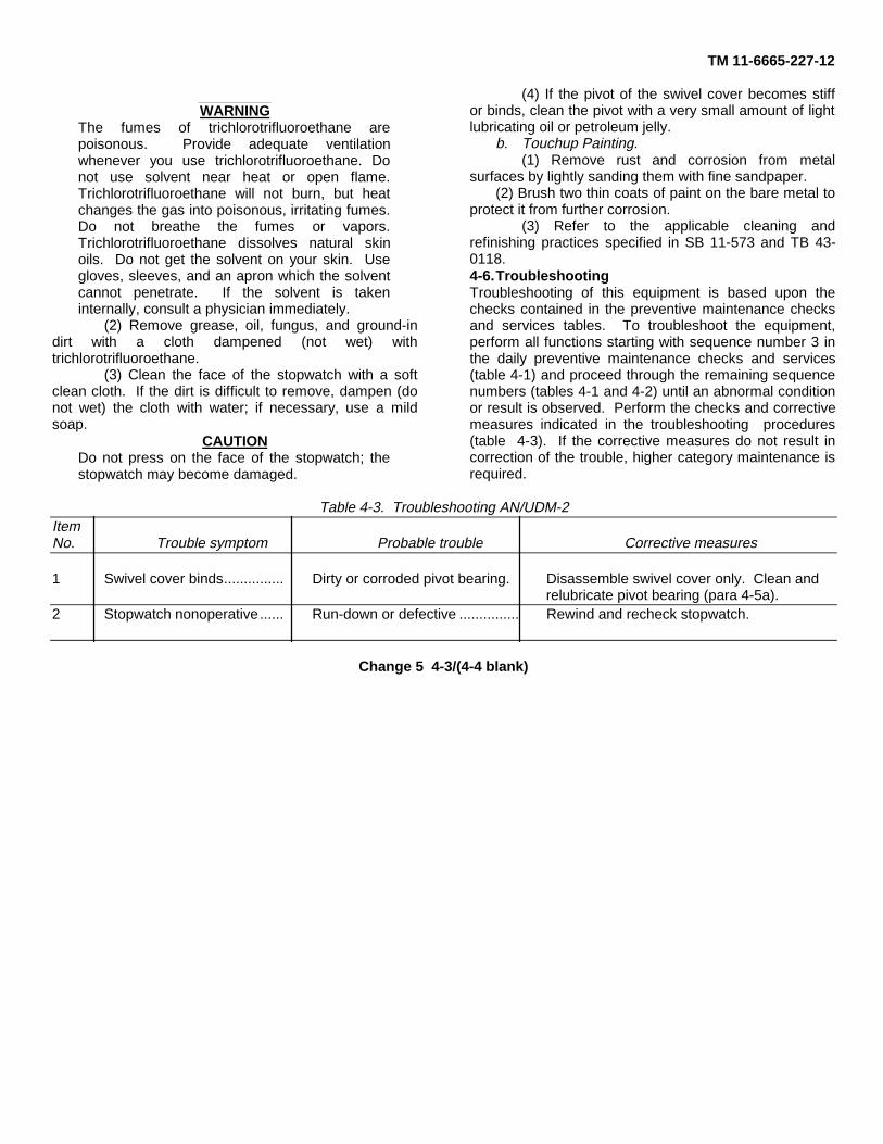
TM 11-6665-227-12
WARNINGThe fumes of trichlorotrifluoroethane arepoisonous. Provide adequate ventilationwhenever you use trichlorotrifluoroethane. Donot use solvent near heat or open flame.Trichlorotrifluoroethane will not burn, but heatchanges the gas into poisonous, irritating fumes.Do not breathe the fumes or vapors.Trichlorotrifluoroethane dissolves natural skinoils. Do not get the solvent on your skin. Usegloves, sleeves, and an apron which the solventcannot penetrate. If the solvent is takeninternally, consult a physician immediately.
(2) Remove grease, oil, fungus, and ground-indirt with a cloth dampened (not wet) withtrichlorotrifluoroethane.
(3) Clean the face of the stopwatch with a softclean cloth. If the dirt is difficult to remove, dampen (donot wet) the cloth with water; if necessary, use a mildsoap.
CAUTIONDo not press on the face of the stopwatch; thestopwatch may become damaged.
(4) If the pivot of the swivel cover becomes stiffor binds, clean the pivot with a very small amount of lightlubricating oil or petroleum jelly.
b. Touchup Painting.(1) Remove rust and corrosion from metal
surfaces by lightly sanding them with fine sandpaper.(2) Brush two thin coats of paint on the bare metal to
protect it from further corrosion.(3) Refer to the applicable cleaning and
refinishing practices specified in SB 11-573 and TB 43-0118.4-6.TroubleshootingTroubleshooting of this equipment is based upon thechecks contained in the preventive maintenance checksand services tables. To troubleshoot the equipment,perform all functions starting with sequence number 3 inthe daily preventive maintenance checks and services(table 4-1) and proceed through the remaining sequencenumbers (tables 4-1 and 4-2) until an abnormal conditionor result is observed. Perform the checks and correctivemeasures indicated in the troubleshooting procedures(table 4-3). If the corrective measures do not result incorrection of the trouble, higher category maintenance isrequired.
Table 4-3. Troubleshooting AN/UDM-2ItemNo. Trouble symptom Probable trouble Corrective measures
1 Swivel cover binds............... Dirty or corroded pivot bearing. Disassemble swivel cover only. Clean andrelubricate pivot bearing (para 4-5a).
2 Stopwatch nonoperative...... Run-down or defective ............... Rewind and recheck stopwatch.
Change 5 4-3/(4-4 blank)
TM 11-6665-227-12
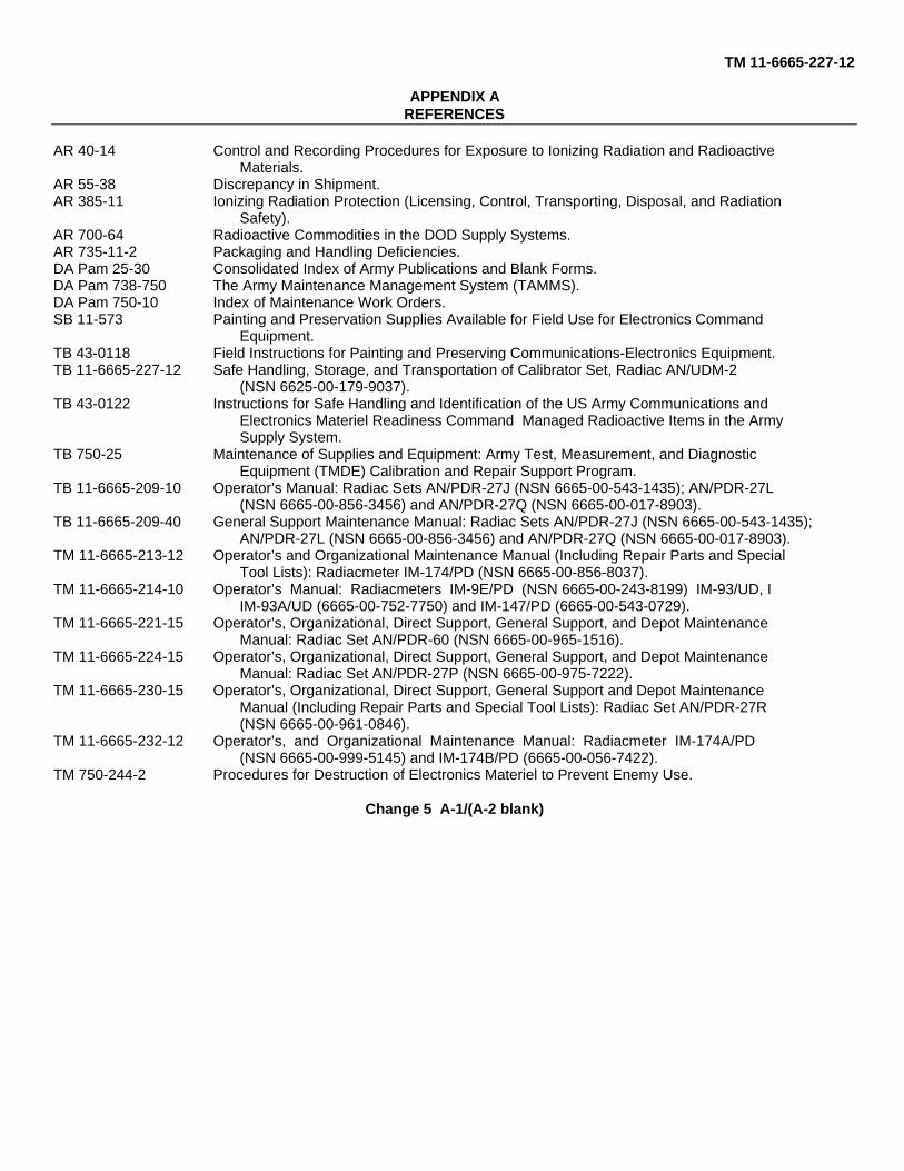
APPENDIX AREFERENCES
AR 40-14 Control and Recording Procedures for Exposure to Ionizing Radiation and RadioactiveMaterials.
AR 55-38 Discrepancy in Shipment.AR 385-11 Ionizing Radiation Protection (Licensing, Control, Transporting, Disposal, and Radiation
Safety).AR 700-64 Radioactive Commodities in the DOD Supply Systems.AR 735-11-2 Packaging and Handling Deficiencies.DA Pam 25-30 Consolidated Index of Army Publications and Blank Forms.DA Pam 738-750 The Army Maintenance Management System (TAMMS).DA Pam 750-10 Index of Maintenance Work Orders.SB 11-573 Painting and Preservation Supplies Available for Field Use for Electronics Command
Equipment.TB 43-0118 Field Instructions for Painting and Preserving Communications-Electronics Equipment.TB 11-6665-227-12 Safe Handling, Storage, and Transportation of Calibrator Set, Radiac AN/UDM-2
(NSN 6625-00-179-9037).TB 43-0122 Instructions for Safe Handling and Identification of the US Army Communications and
Electronics Materiel Readiness Command Managed Radioactive Items in the ArmySupply System.
TB 750-25 Maintenance of Supplies and Equipment: Army Test, Measurement, and DiagnosticEquipment (TMDE) Calibration and Repair Support Program.
TB 11-6665-209-10 Operator’s Manual: Radiac Sets AN/PDR-27J (NSN 6665-00-543-1435); AN/PDR-27L(NSN 6665-00-856-3456) and AN/PDR-27Q (NSN 6665-00-017-8903).
TB 11-6665-209-40 General Support Maintenance Manual: Radiac Sets AN/PDR-27J (NSN 6665-00-543-1435);AN/PDR-27L (NSN 6665-00-856-3456) and AN/PDR-27Q (NSN 6665-00-017-8903).
TM 11-6665-213-12 Operator’s and Organizational Maintenance Manual (Including Repair Parts and SpecialTool Lists): Radiacmeter IM-174/PD (NSN 6665-00-856-8037).
TM 11-6665-214-10 Operator’s Manual: Radiacmeters IM-9E/PD (NSN 6665-00-243-8199) IM-93/UD, IIM-93A/UD (6665-00-752-7750) and IM-147/PD (6665-00-543-0729).
TM 11-6665-221-15 Operator’s, Organizational, Direct Support, General Support, and Depot MaintenanceManual: Radiac Set AN/PDR-60 (NSN 6665-00-965-1516).
TM 11-6665-224-15 Operator’s, Organizational, Direct Support, General Support, and Depot MaintenanceManual: Radiac Set AN/PDR-27P (NSN 6665-00-975-7222).
TM 11-6665-230-15 Operator’s, Organizational, Direct Support, General Support and Depot MaintenanceManual (Including Repair Parts and Special Tool Lists): Radiac Set AN/PDR-27R(NSN 6665-00-961-0846).
TM 11-6665-232-12 Operator’s, and Organizational Maintenance Manual: Radiacmeter IM-174A/PD(NSN 6665-00-999-5145) and IM-174B/PD (6665-00-056-7422).
TM 750-244-2 Procedures for Destruction of Electronics Materiel to Prevent Enemy Use.
Change 5 A-1/(A-2 blank)
TM 11-6665-227-12
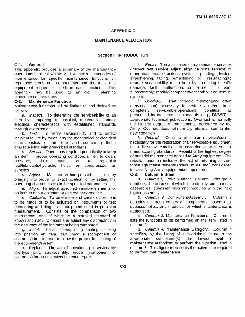
APPENDIX C
MAINTENANCE ALLOCATION
Section I. INTRODUCTION
C-1. GeneralThis appendix provides a summary of the maintenanceoperations for the AN/UDM-2. It authorizes categories ofmaintenance for specific maintenance functions onrepairable items and components and the tools andequipment required to perform each function. Thisappendix may be used as an aid in planningmaintenance operations.C-2. Maintenance FunctionMaintenance functions will be limited to and defined asfollows:
a. Inspect. To determine the serviceability of anitem by comparing its physical, mechanical, and/orelectrical characteristics with established standardsthrough examination.
b. Test. To verify serviceability and to detectincipient failure by measuring the mechanical or electricalcharacteristics of an item and comparing thosecharacteristics with prescribed standards.
c. Service. Operations required periodically to keepan item in proper operating condition, i. e., to clean,preserve, drain, paint, or to replenishfuel/lubricants/hydraulic fluids or compressed airsupplies.
d. Adjust. Maintain within prescribed limits bybringing into proper or exact position, or by setting theoperating characteristics to the specified parameters.
e. Align. To adjust specified variable elements ofan item to about optimum or desired performance.
f. Calibrate. To determine and cause correctionsto be made or to be adjusted on instruments or testmeasuring and diagnostic equipment used in precisionmeasurement. Consists of the comparison of twoinstruments, one of which is a certified standard ofknown accuracy, to detect and adjust any discrepancy inthe accuracy of the instrument being compared.
g. Install. The act of emplacing, seating, or fixinginto position an item, part, module (component orassembly) in a manner to allow the proper functioning ofthe equipment/system.
h. Replace. The act of substituting a serviceablelike-type part, subassembly, model (component orassembly) for an unserviceable counterpart.
i. Repair. The application of maintenance services(inspect, test, service, adjust, align, calibrate, replace) orother maintenance actions (welding, grinding, riveting,straightening, facing, remachining, or resurfacing)torestore serviceability to an item by correcting specificdamage, fault, malfunction, or failure in a part,subassembly, module/component/assembly, end item orsystem.
j. Overhaul. That periodic maintenance effort(service/action) necessary to restore an item to acompletely serviceable/operational condition asprescribed by maintenance standards (e.g., DMWR) inappropriate technical publications. Overhaul is normallythe highest degree of maintenance performed by theArmy. Overhaul does not normally return an item to like-new condition.
k. Rebuild. Consists of those services/actionsnecessary for the restoration of unserviceable equipmentto a like-new condition in accordance with originalmanufacturing standards. Rebuild is the highest degreeof materiel maintenance applied to Army equipment. Therebuild operation includes the act of returning to zerothose age measurements (hours, miles, etc.) consideredin classifying Army equipment/components.C-3. Column Entries
a. Column 1, Group Number. Column 1 lists groupnumbers, the purpose of which is to identify components,assemblies, subassemblies and modules with the nexthigher assembly.
b. Column 2, Component/Assembly. Column 2contains the noun names of components, assemblies,subassemblies, and modules for which maintenance isauthorized.
c. Column 3, Maintenance Functions. Column 3lists the functions to be performed on the item listed incolumn 2.
d. Column 4, Maintenance Category. Column 4specifies, by the listing of a "worktime" figure in theappropriate subcolumn(s), the lowest level ofmaintenance authorized to perform the function listed incolumn 3. This figure represents the active time requiredto perform that maintenance
C-1
TM 11-6665-227-12
function at the indicated category of maintenance. If thenumber of complexity of the tasks within the listedmaintenance function vary at different maintenancecategories, appropriate "worktime" figures will be shownfor each category. The number of man-hours specifiedby the "worktime" figure represents the average timerequired to restore an item (assembly, subassembly,component, module, end item or system) to aserviceable condition under typical field operatingconditions. This time includes preparation time,troubleshooting time and quality assurance/quality controltime in additional to the time required to perform thespecific tasks identified for the maintenance functionsauthorized in the maintenance allocation chart.Subcolumns of column 4 are as follows:
C Operator/crewO OrganizationalF Direct supportH General supportD Depot
e. Column 5, Tools and Equipment. Column 5specifies by code, those common tool sets (not
individual tools) and special tools, test, and supportequipment required to perform the designated function.C-4. Tool and Test Equipment Requirements
(Table 1)a. Tool or Test Equipment Reference Code. The
numbers in this column coincide with the numbers usedin the tools and equipment column of the MAC. Thenumbers indicate the applicable tool or test equipment forthe maintenance functions.
b. Maintenance Category. The codes in thiscolumn indicate the maintenance category allocated thetool or test equipment.
c. Nomenclature. This column lists the noun nameand nomenclature of the tools and test equipmentrequired to perform the maintenance functions.
d. National/NATO Stock Number. This column liststhe National/NATO stock number of the specific tool ortest equipment.
e. Tool Number. This column lists themanufacturer’s part number of the tool followed by theFederal Supply Code for manufacturers (5-digit) inparentheses.
C-2
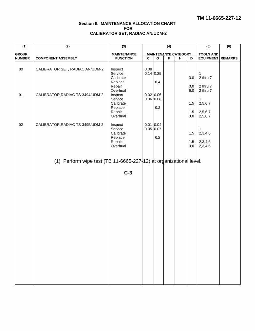
TM 11-6665-227-12Section II. MAINTENANCE ALLOCATION CHART
FORCALIBRATOR SET, RADIAC AN/UDM-2
(1) (2) (3) (4) (5) (6)
GROUP MAINTENANCE MAINTENANCE CATEGORY TOOLS ANDNUMBER COMPONENT ASSEMBLY FUNCTION C O F H D EQUIPMENT REMARKS
00 CALIBRATOR SET, RADIAC AN/UDM-2 Inspect 0.08Service1 0.14 0.25 1Calibrate 3.0 2 thru 7Replace 0.4Repair 3.0 2 thru 7Overhual 6.0 2 thru 7
01 CALIBRATOR,RADIAC TS-3494/UDM-2 Inspect 0.02 0.06Service 0.06 0.08 1Calibrate 1.5 2,5,6,7Replace 0.2Repair 1.5 2,5,6,7Overhual 3.0 2,5,6,7
02 CALIBRATOR,RADIAC TS-3495/UDM-2 Inspect 0.01 0.04Service 0.05 0.07 1Calibrate 1.5 2,3,4,6Replace 0.2Repair 1.5 2,3,4,6Overhual 3.0 2,3,4,6
(1) Perform wipe test (TB 11-6665-227-12) at organizational level.
C-3
TM 11-6665-227-12
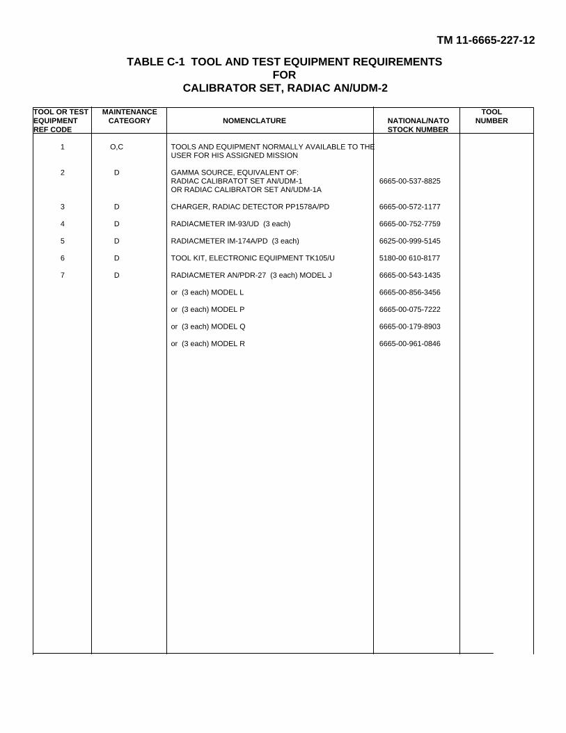
TABLE C-1 TOOL AND TEST EQUIPMENT REQUIREMENTSFOR
CALIBRATOR SET, RADIAC AN/UDM-2
TOOL OR TEST MAINTENANCE TOOLEQUIPMENT CATEGORY NOMENCLATURE NATIONAL/NATO NUMBERREF CODE STOCK NUMBER
1 O,C TOOLS AND EQUIPMENT NORMALLY AVAILABLE TO THEUSER FOR HIS ASSIGNED MISSION
2 D GAMMA SOURCE, EQUIVALENT OF:RADIAC CALIBRATOT SET AN/UDM-1 6665-00-537-8825OR RADIAC CALIBRATOR SET AN/UDM-1A
3 D CHARGER, RADIAC DETECTOR PP1578A/PD 6665-00-572-1177
4 D RADIACMETER IM-93/UD (3 each) 6665-00-752-7759
5 D RADIACMETER IM-174A/PD (3 each) 6625-00-999-5145
6 D TOOL KIT, ELECTRONIC EQUIPMENT TK105/U 5180-00 610-8177
7 D RADIACMETER AN/PDR-27 (3 each) MODEL J 6665-00-543-1435
or (3 each) MODEL L 6665-00-856-3456
or (3 each) MODEL P 6665-00-075-7222
or (3 each) MODEL Q 6665-00-179-8903
or (3 each) MODEL R 6665-00-961-0846
TM 11-6665-227-12
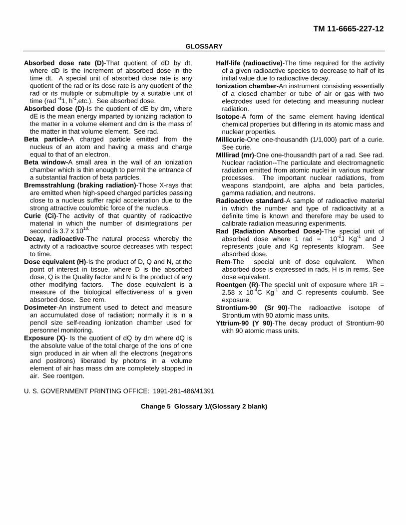
GLOSSARY
Absorbed dose rate (D)-That quotient of dD by dt,where dD is the increment of absorbed dose in thetime dt. A special unit of absorbed dose rate is anyquotient of the rad or its dose rate is any quotient of therad or its multiple or submultiple by a suitable unit oftime (rad -s1, h-1,etc.). See absorbed dose.
Absorbed dose (D)-Is the quotient of dE by dm, wheredE is the mean energy imparted by ionizing radiation tothe matter in a volume element and dm is the mass ofthe matter in that volume element. See rad.
Beta particle-A charged particle emitted from thenucleus of an atom and having a mass and chargeequal to that of an electron.
Beta window-A small area in the wall of an ionizationchamber which is thin enough to permit the entrance ofa substantial fraction of beta particles.
Bremsstrahlung (braking radiation)-Those X-rays thatare emitted when high-speed charged particles passingclose to a nucleus suffer rapid acceleration due to thestrong attractive coulombic force of the nucleus.
Curie (Ci)-The activity of that quantity of radioactivematerial in which the number of disintegrations persecond is 3.7 x 10¹⁰.
Decay, radioactive-The natural process whereby theactivity of a radioactive source decreases with respectto time.
Dose equivalent (H)-Is the product of D, Q and N, at thepoint of interest in tissue, where D is the absorbeddose, Q is the Quality factor and N is the product of anyother modifying factors. The dose equivalent is ameasure of the biological effectiveness of a givenabsorbed dose. See rem.
Dosimeter-An instrument used to detect and measurean accumulated dose of radiation; normally it is in apencil size self-reading ionization chamber used forpersonnel monitoring.
Exposure (X)- Is the quotient of dQ by dm where dQ isthe absolute value of the total charge of the ions of onesign produced in air when all the electrons (negatronsand positrons) liberated by photons in a volumeelement of air has mass dm are completely stopped inair. See roentgen.
Half-life (radioactive)-The time required for the activityof a given radioactive species to decrease to half of itsinitial value due to radioactive decay.
Ionization chamber-An instrument consisting essentiallyof a closed chamber or tube of air or gas with twoelectrodes used for detecting and measuring nuclearradiation.
Isotope-A form of the same element having identicalchemical properties but differing in its atomic mass andnuclear properties.
Millicurie-One one-thousandth (1/1,000) part of a curie.See curie.
Mlllirad (mr)-One one-thousandth part of a rad. See rad.Nuclear radiation--The particulate and electromagneticradiation emitted from atomic nuclei in various nuclearprocesses. The important nuclear radiations, fromweapons standpoint, are alpha and beta particles,gamma radiation, and neutrons.
Radioactive standard-A sample of radioactive materialin which the number and type of radioactivity at adefinite time is known and therefore may be used tocalibrate radiation measuring experiments.
Rad (Radiation Absorbed Dose)-The special unit ofabsorbed dose where 1 rad = 10-2J Kg-1 and Jrepresents joule and Kg represents kilogram. Seeabsorbed dose.
Rem-The special unit of dose equivalent. Whenabsorbed dose is expressed in rads, H is in rems. Seedose equivalent.
Roentgen (R)-The special unit of exposure where 1R =2.58 x 10⁻⁴C Kg-1 and C represents coulumb. Seeexposure.
Strontium-90 (Sr 90)-The radioactive isotope ofStrontium with 90 atomic mass units.
Yttrium-90 (Y 90)-The decay product of Strontium-90with 90 atomic mass units.
U. S. GOVERNMENT PRINTING OFFICE: 1991-281-486/41391
Change 5 Glossary 1/(Glossary 2 blank)
TM 11-6665-227-12
By Order of the Secretary of the Army:
FRED C. WEYANDGeneral, United States Army,
Official: Chief of Staff.
VERNE L. BOWERSMajor General, United States Army,The Adjutant General.
DISTRIBUTION:To be distributed in accordance with DA Form 12-50 (qty rqr block no. 65),Operator requirements for AN/UDM-2.
*US. GOVERNMENT PRINTING OFFICE 1986 0-181-421 (41597)
TM 11-6665-227-12
TM 11-6665-227-12
TM 11-6665-227-12

PIN: 019514-000