Embed Size (px)
Citation preview
1
This accepted author manuscript is copyrighted and published by
Elsevier. It is posted here by agreement between Elsevier and
MTA. The definitive version of the text was subsequently
published in International Journal of Pressure Vessels and Piping,
134, 2015, DOI: 10.1016/j.ijpvp.2015.08.006. Available under
license CC-BY-NC-ND.
Determination of hoop direction effective elastic moduli of non-circular profile, fiber
reinforced polymer composite sewer liner pipes from lateral ring compression tests
Gergely Czél1,2 and Dénes Takács3
1Department of Polymer Engineering, Faculty of Mechanical Engineering, Budapest
University of Technology and Economics
H-1111 Budapest, Műegyetem rkp. 3. Hungary
2MTA–BME Research Group for Composite Science and Technology, Budapest University
of Technology and Economics
H-1111 Budapest, Műegyetem rkp. 3. Hungary
3Department of Applied Mechanics, Faculty of Mechanical Engineering, Budapest University
of Technology and Economics
H-1111 Budapest, Műegyetem rkp. 3. Hungary
Corresponding author: Czél G. E-mail: [email protected],
tel.: +36 1 463 1487, fax: +36 1 463 1527
Abstract
A new material property determination method is presented for the calculation of
effective elastic moduli of non-circular ring specimens cut from filament wound oval profile
polymer composite sewer liner pipes. The hoop direction elastic moduli was determined using
the test results obtained from ring compression tests, which is a very basic setup, and requires
no special equipment. Calculations were executed for many different oval profiles, and
diagrams were constructed, from which the cross section dependent Ceff constants can be
taken. The new method was validated by the comparison of tests and finite element analysis
2
results. The calculation method and the diagrams are essential design tools for engineers, and
a big step forward in sizing non-circular profile liner pipes .
Keywords: Composite pipe, Ring compression test, Glass fiber, Polyester, Finite element
method
1. Introduction
High performance composite materials consisting of thermosetting polymer matrix
(mainly epoxy, vinylester or unsaturated polyester resins) and reinforcing fibers (carbon, glass
or aramide fibers) show high strength, acceptable elastic modulus, low density and high
chemical resistance. These special properties have made fiber reinforced polymer composites
suitable for the underground piping industry, where low maintenance need of these materials
is an additional benefit [1]. Glass fiber reinforced unsaturated polyester (GF/UP) pipes and
vessels have been manufactured for more than four decades, and applied successfully in food
industries, and in underground water and sewerage piping [2]. Glass and carbon fiber
reinforced composites are also suitable for repairing pressure pipes [3]. Major advantages of
polymer composite pipes compared to steel ones are low weight, which decreases
construction and transportation costs, corrosion and chemical resistance [4] that reduces
maintenance costs and extends the lifetime of the pipes. Composite pipes have higher strength
and stiffness compared to thermoplastic polymer pipes (PE, PP, PVC), which gives higher
pressure resistance and load bearing capacity, and finally allows the designer to use lower
wall thicknesses.
Composite pipes are manufactured mainly by filament winding and rotational casting,
and they can be operated under gravity or internal pressure. The former manufacturing
technology is more common for high performance pipes mainly because the anisotropic
mechanical properties of the pipe material can be fitted to the loads by changing the winding
angle [5],[6].
In the early stage of sewerage piping, various pipe cross sections were built from
stones or bricks with masonry technique. Notable amount of these pipes are older than a
hundred years, and is in need for rehabilitation. Effective ways of repairing underground
pipes are the trenchless lining technologies, where the surface traffic is only slightly affected
by the construction works [7]. The most common sewer pipe lining technologies are “cured in
3
place pipe” lining (CIPP), where a preformed hose impregnated by uncured resin is pulled
into the section to be repaired, and then filled and cured with pressurized steam; and the
“short pipe process”, where prefabricated (cured) liner pipe sections are pulled or pushed into
the old pipe. Both technologies are capable of lining non-circular profile pipes. In this study
we are focusing on pre-fabricated filament wound sewer lining pipes with special symmetric
oval cross sections which consist of three circular arc sections with different radii.
Besides their advantageous special properties, polymer composites show some
uncommon behavior compared to conventional structural materials (metals). Most of the
unusual properties, such as temperature dependent properties [8],[9], degradation and water
absorption [10],[11] are due to the macromolecular structure of the polymer matrix material.
Composites also show uncommon damage modes in comparison with tough materials, such as
various fracture types [12] due to their fiber reinforced laminated structure. The fibrous
reinforcing structure of the composite parts causes anisotropy in the material properties,
which makes the design process more difficult. There is a significant need for research in the
field of structural design of sewer liners [13]. Researchers are developing better sizing
methods which require more accurate material properties. Because of the uncommon material
behavior, hundreds of possible fiber–matrix combinations and sensitive curing process [14],
testing is even more important in case of composite materials than in case of metals. The most
effective tests should be executed on the composite parts themselves, because the reinforcing
fiber structure can be kept unaffected in this way.
Testing of pipe materials is always problematic, because it is difficult to fabricate
standard specimens from a pipe. Longitudinal tensile or compression specimens have
curvatures in the transverse direction that is why special adhesive materials and tabs are
needed to make the clamping areas even. This way the tensile properties can be evaluated
using EN 1393 using a special cross sectional area calculation method developed in a former
study [15]. Only curved specimens can be taken from the circumferential direction of the
pipe, on which flexural tests can be executed according to EN 13566-4. The mechanical
properties in the circumferential direction can be determined from circumferential tensile tests
(EN 1394) and from ring compression tests (EN 1228). The cited standards often give
methods for determining product properties instead of material properties. Product properties
are suitable for quality control and other comparative tests, but cannot be applied for
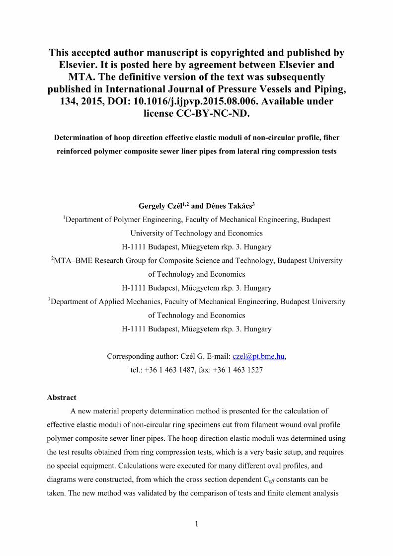
comparing different materials and product types. Ring compression test is a very basic setup
(Fig. 1), which does not modify the reinforcing structure of the pipe and for which no special
equipment is needed.
4
Fig. 1 Ring compression test setup with regular egg-shaped profile specimen
Applying an appropriate evaluation method, the hoop direction effective elastic
moduli (Eeff) of the tested pipe materials, which is the most important design parameter, can
be calculated from ring compression tests even for non-circular cross sections. The static
design methods of sewer liner pipes, including non-circular profile ones [16],[17], operating
under gravity, consider the groundwater or grout injection pressure as outer pressure loading.
The hoop direction effective elastic modulus of the pipe material is therefore the most
important input parameter for the design methods. In the following paragraphs, the shape of
the examined cross sections and the new test evaluation method will be explained in details.
The aim of this paper is to provide design engineers with a simple test and a quick
evaluation method which is capable of determining the hoop direction effective elastic
modulus, the most important mechanical property of non-circular profile composite pipes.
The proposed simple test can also be used for quality and general product control and it is
applicable to a wide variety of pipe cross-sections.
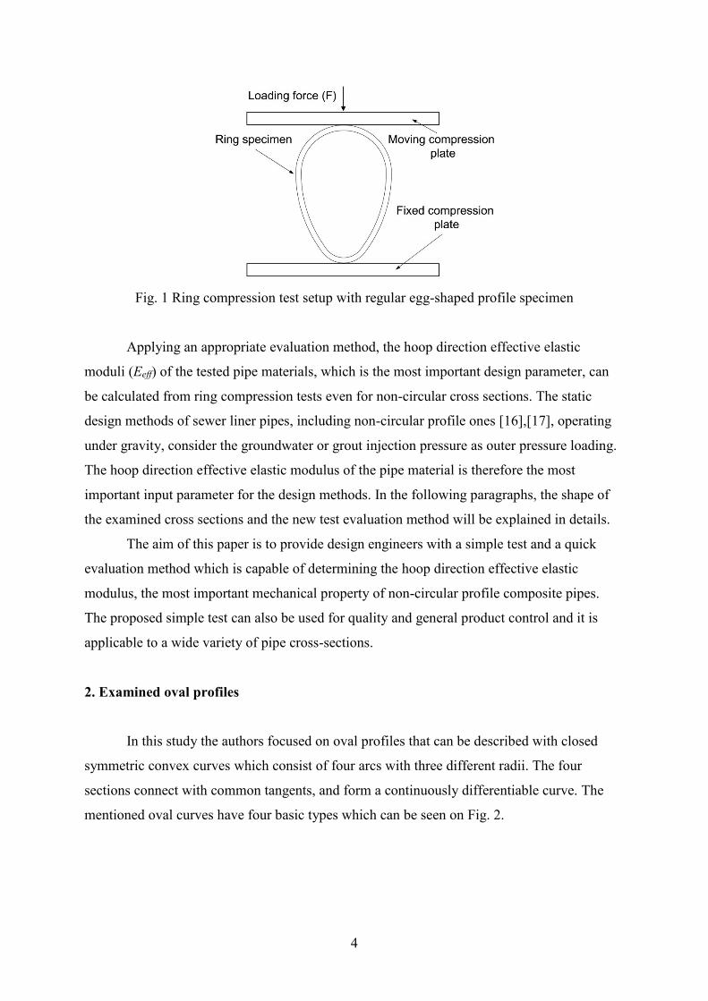
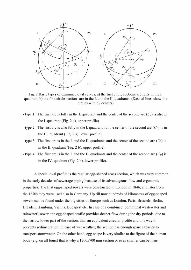
2. Examined oval profiles
In this study the authors focused on oval profiles that can be described with closed
symmetric convex curves which consist of four arcs with three different radii. The four
sections connect with common tangents, and form a continuously differentiable curve. The
mentioned oval curves have four basic types which can be seen on Fig. 2.
5
Fig. 2 Basic types of examined oval curves, a) the first circle sections are fully in the I.
quadrant, b) the first circle sections are in the I. and the II. quadrants. (Dashed lines show the
circles with C1 centers)
- type 1.: The first arc is fully in the I. quadrant and the center of the second arc (C2) is also in
the I. quadrant (Fig. 2 a), upper profile).
- type 2.: The first arc is also fully in the I. quadrant but the center of the second arc (CII) is in
the III. quadrant (Fig. 2 a), lower profile).
- type 3.: The first arc is in the I. and the II. quadrants and the center of the second arc (C2) is
in the II. quadrant (Fig. 2 b), upper profile).
- type 4.: The first arc is in the I. and the II. quadrants and the center of the second arc (CII) is
in the IV. quadrant (Fig. 2 b), lower profile).
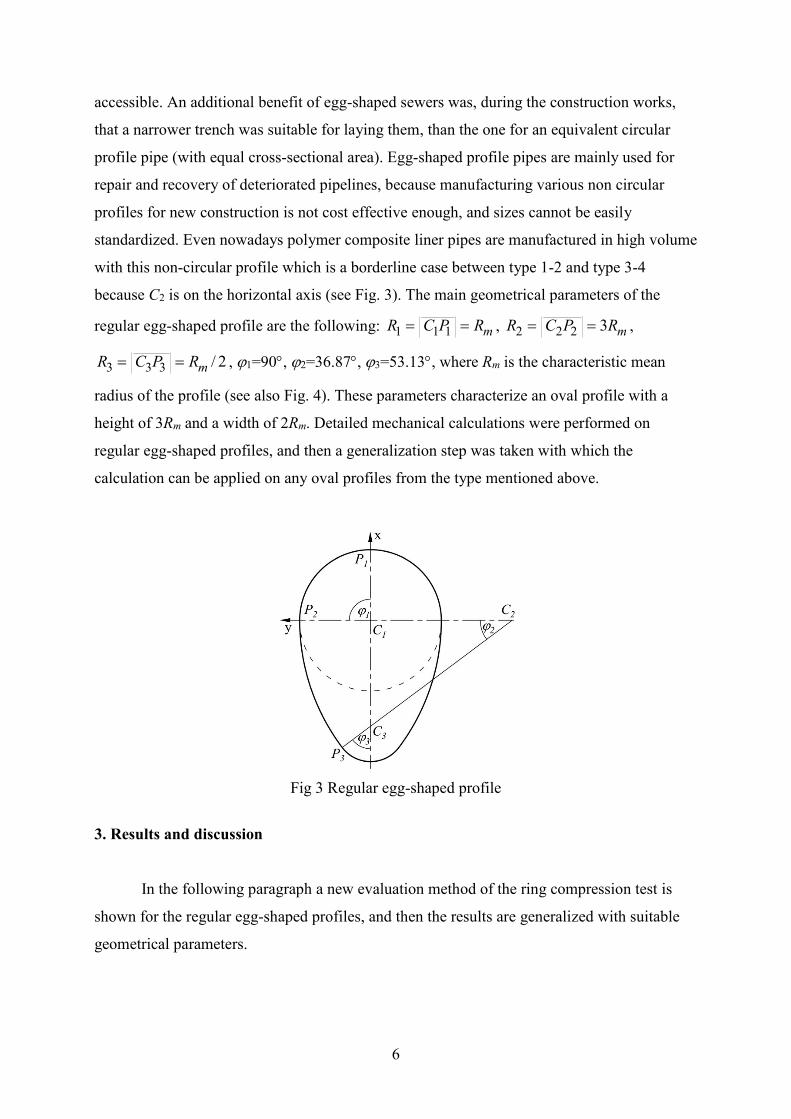
A special oval profile is the regular egg-shaped cross section, which was very common
in the early decades of sewerage piping because of its advantageous flow and ergonomic
properties. The first egg-shaped sewers were constructed in London in 1846, and later from
the 1870s they were used also in Germany. Up till now hundreds of kilometres of egg-shaped
sewers can be found under the big cities of Europe such as London, Paris, Brussels, Berlin,
Dresden, Hamburg, Vienna, Budapest etc. In case of a combined (communal wastewater and
rainwater) sewer, the egg-shaped profile provides deeper flow during the dry periods, due to
the narrow lower part of the section, than an equivalent circular profile and this way it
prevents sedimentation. In case of wet weather, the section has enough spare capacity to
transport stormwater. On the other hand, egg-shape is very similar to the figure of the human
body (e.g. on all fours) that is why a 1200x700 mm section or even smaller can be man-
6
accessible. An additional benefit of egg-shaped sewers was, during the construction works,
that a narrower trench was suitable for laying them, than the one for an equivalent circular
profile pipe (with equal cross-sectional area). Egg-shaped profile pipes are mainly used for
repair and recovery of deteriorated pipelines, because manufacturing various non circular
profiles for new construction is not cost effective enough, and sizes cannot be easily
standardized. Even nowadays polymer composite liner pipes are manufactured in high volume
with this non-circular profile which is a borderline case between type 1-2 and type 3-4
because C2 is on the horizontal axis (see Fig. 3). The main geometrical parameters of the
regular egg-shaped profile are the following: mRPCR 111 , mRPCR 3222 ,
2/333 mRPCR , 1=90, 2=36.87, 3=53.13, where Rm is the characteristic mean
radius of the profile (see also Fig. 4). These parameters characterize an oval profile with a
height of 3Rm and a width of 2Rm. Detailed mechanical calculations were performed on
regular egg-shaped profiles, and then a generalization step was taken with which the
calculation can be applied on any oval profiles from the type mentioned above.
Fig 3 Regular egg-shaped profile
3. Results and discussion
In the following paragraph a new evaluation method of the ring compression test is
shown for the regular egg-shaped profiles, and then the results are generalized with suitable
geometrical parameters.
7
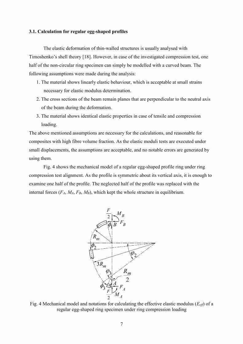
3.1. Calculation for regular egg-shaped profiles
The elastic deformation of thin-walled structures is usually analysed with
Timoshenko’s shell theory [18]. However, in case of the investigated compression test, one
half of the non-circular ring specimen can simply be modelled with a curved beam. The
following assumptions were made during the analysis:
1. The material shows linearly elastic behaviour, which is acceptable at small strains
necessary for elastic modulus determination.
2. The cross sections of the beam remain planes that are perpendicular to the neutral axis
of the beam during the deformation.
3. The material shows identical elastic properties in case of tensile and compression
loading.
The above mentioned assumptions are necessary for the calculations, and reasonable for
composites with high fibre volume fraction. As the elastic moduli tests are executed under
small displacements, the assumptions are acceptable, and no notable errors are generated by
using them.
Fig. 4 shows the mechanical model of a regular egg-shaped profile ring under ring
compression test alignment. As the profile is symmetric about its vertical axis, it is enough to
examine one half of the profile. The neglected half of the profile was replaced with the
internal forces (FA, MA, FB, MB), which kept the whole structure in equilibrium.
Fig. 4 Mechanical model and notations for calculating the effective elastic modulus (Eeff) of a
regular egg-shaped ring specimen under ring compression loading
8
The concentrated force F/2 is considered as the external load for the half of the profile, acting
from the compression plates. The equilibrium equations of the examined structure can be
written with equations (1) and (2).
0BAFF (1)
03 mBBA RFMM (2)
To determine the internal forces of the structure, further equations are needed. The missing
equations can be written using the work theorem of statics. First, the general form of the strain
energy has to be written paying attention only to the dominant forces (equation (3)).
sAE
sNs
IE
sMU
l effl eff
h d2
)(d
2
)( 22
(3)
where Mh(s) and N(s) are the bending and normal stress resultant functions along the arc
length, respectively, I is the moment of inertia of the model beam (ring specimen) calculated
with respect to the axis of bending, A is the cross-sectional area of the model beam. As the
regular egg-shaped profile consists of three arcs, the bending and the normal stress resultant
functions can be written as a piecewise function, which is characterized by three sections.
Functions are given by equations (4)-(9).
1111 sin2
cos1 mmBBh RF
RFMM (4)
2222 cos132
sin3 mmmBBh RRF
RRFMM (5)
333333 sin22
cos2
5,2
mm
kBBh
RFRRFMM (6)
1111 cossin2
BFF
N (7)
2222 sincos2
BFF
N (8)
333333 cossin2
BFF
N (9)
where 2
01
,
220 and
233 20
. Using the functions above, the strain
energy can be written as functions of the corresponding angles (10).
9
3
3
0
323
2
2
0
222
1
2
0
121
3
3
0
323
2
2
0
222
1
2
0
121
d22
d32
d2
d22
d32
d2
m
effm
effm
eff
m
eff
hm
eff
hm
eff
h
R
AE
NR
AE
NR
AE
N
R
IE
MR
IE
MR
IE
MU
(10)
According to the theorem of Castigliano [19], the partial derivatives of the strain energy with
respect to the internal forces are zero and the partial derivative with respect to the active
forces gives the displacement (f) in the direction of the selected force. Using this theorem,
equations (11)-(13) can be written.
0
BF
U (11)
0
BM
U (12)
fF
U
2
(13)
The system of equations (1), (2) and (11)-(13) can be solved, and the internal forces (FA, MA,
FB, MB) and the effective elastic modulus (Eeff) of the pipe material can be calculated. The
analytical solution leads to a complicated formula of Eeff, in which the geometrical parameters
and the force-displacement pairs of the test results appear. To obtain a simpler formula, the
normal stress resultant function was neglected in the strain energy. Using the simplified
formula of strain energy resulted in only 0.06 % error in the Eeff values calculated from our
experimental data. In this simplified case, the effective moduli of the pipe material can be
calculated from ring compression test results using formula (14).
f
F
I
RE meff
3
1691.0 (14)
where 3 /12I l t is the moment of inertia of the pipe wall calculated with respect to the axis
of bending, where l is the width of the ring specimen, t is the wall thickness of the specimen.
Finally, /F f is the initial ramp of the force-vertical displacement curve of the ring
compression test.
10
3.2. Calculation for general oval profiles
Writing the bending resultant functions for a general oval profile with the notations of
Figures 2, 3 and 4, equations (15)-(17) are given for the three different arcs.
111111 cos1sin2
RFRF
MM BBh (15)
2121211
122121122
coscoscos1
sinsinsin2
RRRF
RRRF
MM
B
Bh (16)
33333321211
33333212121133
coscoscoscoscos1
sinsinsinsinsin2
RRRRRF
RRRRRF
MM
B
Bh
(17)
where 110 , 220 and 21330 .
If the bending resultant function is considered in the strain energy only, the calculation of the
regular egg-shaped profile can be repeated, and the effective modulus Eeff can be calculated
for the general oval profile by formula (18).
f
F
I
RCE effeff
31 (18)
where the coefficient Ceff is typical of the investigated profile (for example, in case of a
regular egg-shaped profile Ceff =0.169). R1 is the first mean radius of the profile (in case of a
regular egg-shaped profile R1=Rm).
Oval profiles can be described with four independent geometrical parameters, namely,
R1, R2, 1, 2. Obviously, all the parameters are necessary to calculate the elastic modulus Eeff
of the pipe material but the classification of the oval profiles and the calculation of the
coefficient Ceff can be done with the help of the quotients R2/R1, 2/1 and the value of 1.
This means that Ceff is a hyper surface in the (R2/R1, 2/1, 1) three dimensional parameter
space, which can be represented by its contour curves in plane. Actually, the quotient 2/1
was fixed and the contours of Ceff values in the (R2/R1, 1) plane were constructed. For
example, Fig. 5 shows the contours for 2/1=0.40966 which is characteristic of the regular
egg-shaped profiles.
11
Fig. 5 Ceff values on the R2/R1-1 plane for 2/1=0.40966 which is characteristic of the
regular egg-shaped profiles
Boundary curves in Fig. 5 shows the geometrical boundaries of the examined profile, which
are given by equations (19)-(20).
1
21
1
(19)
1221
2
cotsincos1
1
R
R (20)
The vertical line (equation (19)) shows that the sum of the three angles (1, 2, 3) is always
. The upper (curved) boundary (equation (20)) is coming from the definition of the examined
oval profiles. The contour curves similar to the ones in Fig. 5 can be constructed for different
values of 2/1, and Ceff values can be calculated for each possible oval profile.
The constructed contour curves are very useful for designer engineers because an
essential material property, namely the hoop direction effective elastic modulus (Eeff) can be
12
calculated from a simple ring compression test for any oval profile using them. Therefore,
several figures were constructed and some of them were added to the Appendix for different
values of 2/1. As an extreme case of the oval profiles, circular profile can be taken into
account, which can be characterized by R2/R1=1. For this special case, Ceff =0.14866
independently from the values of the other parameters. The circular case is present in all
constructed contour diagrams at R2/R1=1. The design engineers can find the right chart using
the geometrical parameters of the examined profile, and the necessary Ceff value can be
obtained by interpolation.
3.3. Verification of the new method
The developed effective modulus calculation method was applied to ring compression
test results and verified by comparing the experimental load-displacement graphs to those
obtained from a Finite Element Analysis (FEA) using the experimental effective moduli.
Quasi-static ring compression tests (see Fig. 1) were executed on three egg-shaped
profile (see Fig. 3) ring specimens cut from a filament wound glass fiber reinforced
unsaturated polyester composite pipe with fiber volume fraction vf=53.9±2.2 % between stiff,
flat, parallel steel compression plates at 6 mm/min cross-head speed on a Zwick Z050 type 50
kN rated computer controlled universal test machine. The nominal geometric properties of the
tested rings were the following: characteristic mean radius: Rm=80 mm, nominal wall
thickness: t=2.4 mm, width: l=40 mm, cross- sectional height: h=3Rm=240 mm, cross-
sectional width: b=2Rm=160 mm. Each rings were compressed three times until the
displacement of the upper compression plate reached 10 mm. The obtained nine test curves
were aggregated into an average curve for easier comparison to model results. The effective
elastic moduli of the specimens calculated with the developed method using equation (14) can
be seen in Table 1. The initial slopes of the displacement- compression force curves ( /F f
) were determined graphically. Finally mean and standard deviation were calculated from all
nine calculated hoop direction effective moduli values, which was Eeff=35.76±0.87 GPa.
13
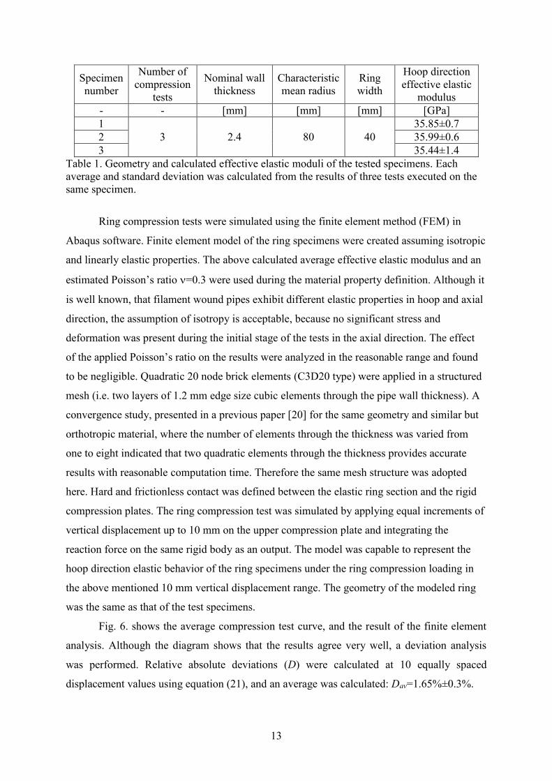
Specimen
number
Number of
compression
tests
Nominal wall
thickness
Characteristic
mean radius
Ring
width
Hoop direction
effective elastic
modulus
- - [mm] [mm] [mm] [GPa]
1
3 2.4 80 40
35.85±0.7
2 35.99±0.6
3 35.44±1.4
Table 1. Geometry and calculated effective elastic moduli of the tested specimens. Each
average and standard deviation was calculated from the results of three tests executed on the
same specimen.
Ring compression tests were simulated using the finite element method (FEM) in
Abaqus software. Finite element model of the ring specimens were created assuming isotropic
and linearly elastic properties. The above calculated average effective elastic modulus and an
estimated Poisson’s ratio =0.3 were used during the material property definition. Although it
is well known, that filament wound pipes exhibit different elastic properties in hoop and axial
direction, the assumption of isotropy is acceptable, because no significant stress and
deformation was present during the initial stage of the tests in the axial direction. The effect
of the applied Poisson’s ratio on the results were analyzed in the reasonable range and found
to be negligible. Quadratic 20 node brick elements (C3D20 type) were applied in a structured
mesh (i.e. two layers of 1.2 mm edge size cubic elements through the pipe wall thickness). A
convergence study, presented in a previous paper [20] for the same geometry and similar but
orthotropic material, where the number of elements through the thickness was varied from
one to eight indicated that two quadratic elements through the thickness provides accurate
results with reasonable computation time. Therefore the same mesh structure was adopted
here. Hard and frictionless contact was defined between the elastic ring section and the rigid
compression plates. The ring compression test was simulated by applying equal increments of
vertical displacement up to 10 mm on the upper compression plate and integrating the
reaction force on the same rigid body as an output. The model was capable to represent the
hoop direction elastic behavior of the ring specimens under the ring compression loading in
the above mentioned 10 mm vertical displacement range. The geometry of the modeled ring
was the same as that of the test specimens.
Fig. 6. shows the average compression test curve, and the result of the finite element
analysis. Although the diagram shows that the results agree very well, a deviation analysis
was performed. Relative absolute deviations (D) were calculated at 10 equally spaced
displacement values using equation (21), and an average was calculated: Dav=1.65%±0.3%.
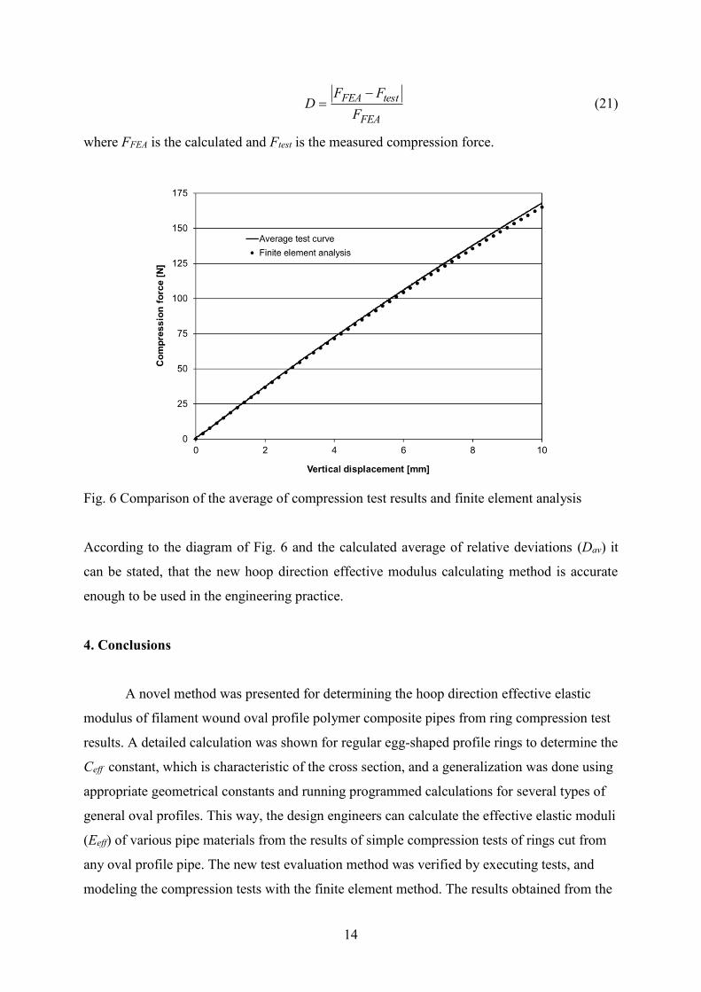
14
FEA
testFEA
F
FFD
(21)
where FFEA is the calculated and Ftest is the measured compression force.
Fig. 6 Comparison of the average of compression test results and finite element analysis
According to the diagram of Fig. 6 and the calculated average of relative deviations (Dav) it
can be stated, that the new hoop direction effective modulus calculating method is accurate
enough to be used in the engineering practice.
4. Conclusions
A novel method was presented for determining the hoop direction effective elastic
modulus of filament wound oval profile polymer composite pipes from ring compression test
results. A detailed calculation was shown for regular egg-shaped profile rings to determine the
Ceff constant, which is characteristic of the cross section, and a generalization was done using
appropriate geometrical constants and running programmed calculations for several types of
general oval profiles. This way, the design engineers can calculate the effective elastic moduli
(Eeff) of various pipe materials from the results of simple compression tests of rings cut from
any oval profile pipe. The new test evaluation method was verified by executing tests, and
modeling the compression tests with the finite element method. The results obtained from the
15
tests and modeling, agreed well, proving that the method is capable of calculating the
effective elastic modulus accurately enough for engineering practice. Using the new method,
engineers can perform quick and accurate sizing of the pipes assuring safe operation, saving
material and energy. The presented test and evaluation method is essential, because accurate
prediction of material properties of composite materials before manufacturing is difficult.
This is the reason, why testing is a vital part of the design process of composite materials.
Appendix
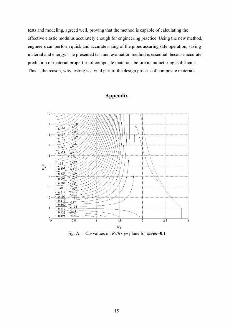
Fig. A. 1 Ceff values on R2/R1-1 plane for 2/1=0.1
16
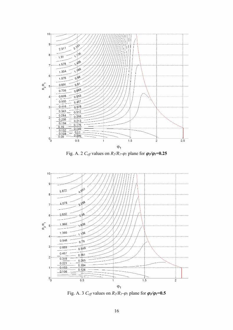
Fig. A. 2 Ceff values on R2/R1-1 plane for 2/1=0.25
Fig. A. 3 Ceff values on R2/R1-1 plane for 2/1=0.5
17
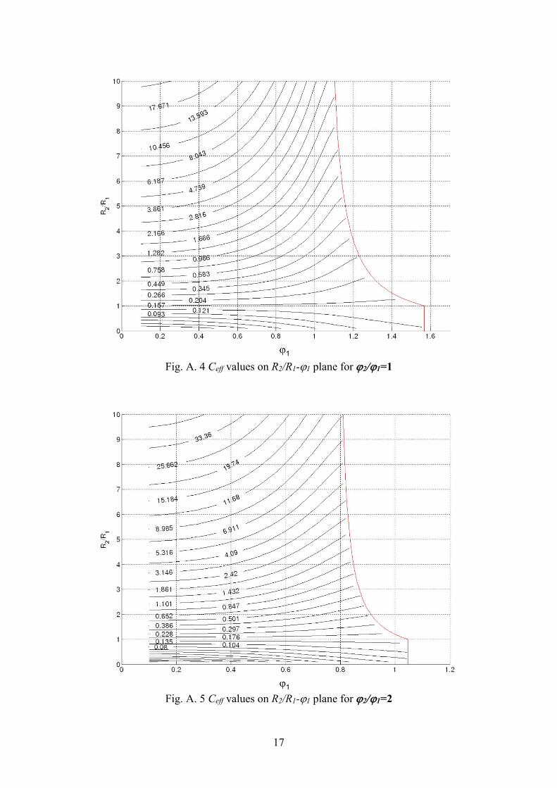
Fig. A. 4 Ceff values on R2/R1-1 plane for 2/1=1
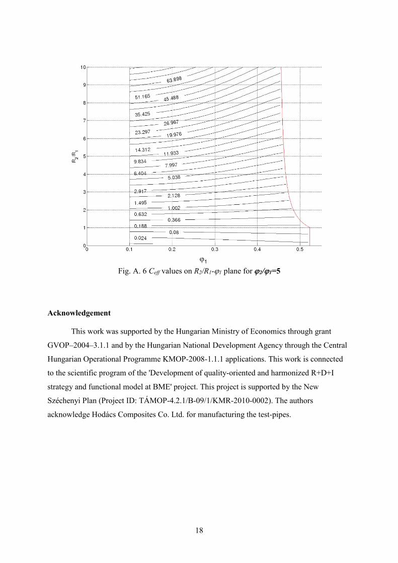
Fig. A. 5 Ceff values on R2/R1-1 plane for 2/1=2
18
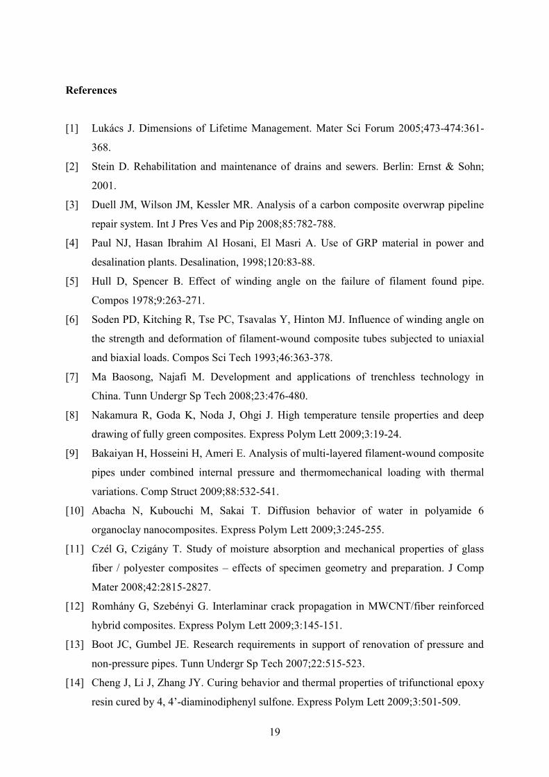
Fig. A. 6 Ceff values on R2/R1-1 plane for 2/1=5
Acknowledgement
This work was supported by the Hungarian Ministry of Economics through grant
GVOP–2004–3.1.1 and by the Hungarian National Development Agency through the Central
Hungarian Operational Programme KMOP-2008-1.1.1 applications. This work is connected
to the scientific program of the 'Development of quality-oriented and harmonized R+D+I
strategy and functional model at BME' project. This project is supported by the New
Széchenyi Plan (Project ID: TÁMOP-4.2.1/B-09/1/KMR-2010-0002). The authors
acknowledge Hodács Composites Co. Ltd. for manufacturing the test-pipes.
19
References
[1] Lukács J. Dimensions of Lifetime Management. Mater Sci Forum 2005;473-474:361-
368.
[2] Stein D. Rehabilitation and maintenance of drains and sewers. Berlin: Ernst & Sohn;
2001.
[3] Duell JM, Wilson JM, Kessler MR. Analysis of a carbon composite overwrap pipeline
repair system. Int J Pres Ves and Pip 2008;85:782-788.
[4] Paul NJ, Hasan Ibrahim Al Hosani, El Masri A. Use of GRP material in power and
desalination plants. Desalination, 1998;120:83-88.
[5] Hull D, Spencer B. Effect of winding angle on the failure of filament found pipe.
Compos 1978;9:263-271.
[6] Soden PD, Kitching R, Tse PC, Tsavalas Y, Hinton MJ. Influence of winding angle on
the strength and deformation of filament-wound composite tubes subjected to uniaxial
and biaxial loads. Compos Sci Tech 1993;46:363-378.
[7] Ma Baosong, Najafi M. Development and applications of trenchless technology in
China. Tunn Undergr Sp Tech 2008;23:476-480.
[8] Nakamura R, Goda K, Noda J, Ohgi J. High temperature tensile properties and deep
drawing of fully green composites. Express Polym Lett 2009;3:19-24.
[9] Bakaiyan H, Hosseini H, Ameri E. Analysis of multi-layered filament-wound composite
pipes under combined internal pressure and thermomechanical loading with thermal
variations. Comp Struct 2009;88:532-541.
[10] Abacha N, Kubouchi M, Sakai T. Diffusion behavior of water in polyamide 6
organoclay nanocomposites. Express Polym Lett 2009;3:245-255.
[11] Czél G, Czigány T. Study of moisture absorption and mechanical properties of glass
fiber / polyester composites – effects of specimen geometry and preparation. J Comp
Mater 2008;42:2815-2827.
[12] Romhány G, Szebényi G. Interlaminar crack propagation in MWCNT/fiber reinforced
hybrid composites. Express Polym Lett 2009;3:145-151.
[13] Boot JC, Gumbel JE. Research requirements in support of renovation of pressure and
non-pressure pipes. Tunn Undergr Sp Tech 2007;22:515-523.
[14] Cheng J, Li J, Zhang JY. Curing behavior and thermal properties of trifunctional epoxy
resin cured by 4, 4’-diaminodiphenyl sulfone. Express Polym Lett 2009;3:501-509.
20
[15] Czél G, Czigány T. Development and analysis of filament wound new composite pipes
made of glass fibre reinforced 3P resin. Macromol Symp 2006;239:232-244.
[16] Thépot O. Structural design of oval-shaped sewer linings. Thin- Walled Struct
2001;39:499-518.
[17] Thépot O. A new design method for non-circular sewer linings. Trenchless Technol Res
2000;15:25-41.
[18] Timoshenko S, Woinowsky-Krieger S. Theory of plates and shells. New York: Mc
Graw-Hill; 1959.
[19] Beer FP, Johnston ER, DeWolf JT. Mechanics of Materials. London: Mc Graw-Hill
Inc.; 1992.
[20] Czél G, Czigány T. Finite element method assisted stiffness design procedure for non-
circular profile composite wastewater pipe linings. Comp Struct 2014;112:78-84.