Embed Size (px)
Citation preview
LTB RESISTANCE OF BEAMS INFLUENCED BY PLASTIC RESERVE OR LOCAL BUCKLING
Y. Koleková*, I. Baláž**
Abstract: The results of original procedure concerning calculation of the values of the critical moments Mcr using approximate formulae convenient for educational and standardization purposes are presented. The authors formulae are today used in many international and national standardization documents (e.g. in several Eurocodes and their National Annexes), in engineering practice of 32 countries and in educational process at many Universities (e.g. in EPU de São Paulo, EPFL Lausanne, etc.). New C1 values are presented for beams under combination of uniform loading and unequal end moments. Development of useful modification of Eurocode formulae for lateral torsional buckling resistance Mb,Rd, which enable to show very clearly the influence of plastic resistance and local buckling on LTB resistance of metal (steel, stainless steel, aluminium) and timber beams calculated by any of 4 Eurocode methods.
Keywords: Critical moment, LTB resistance, steel and aluminium beams, Eurocodes.
1. Introduction
In different Eurocodes: EN 1993-1-1 (2005), EN 1993-1-4 (2006) for steel, EN 1995-1-1 (2004) for timber, EN 1994-1-1 (2004) for composite steel and concrete and EN 1999-1-1 (2007) for aluminium alloys structures, different ways of calculations of critical moments and resistances of laterally unrestrained beams are used. It was shown in the papers Baláž, I. – Koleková, Y. (2000 b, c, 2002 a, b, 2004 a, b) that rules of different Eurocodes concerning lateral torsional buckling could be unified. In this paper EN 1993-1-1 (2005) (ENV 1993-1-1, 1992), EN 1993-1-4 (2006) and EN 1999-1-1 (2007) will be analysed. Lateral torsional buckling of timber structures including analysis of EN 1995-1-1 rules was analysed in Baláž, I. – Koleková, Y. (2004 a, b) and in Baláž (2005).
2. Critical moment crM
Critical moment crM is an important quantity, which is needed for calculation of relative slenderness
LTλ . The value of crM may be calculated: (i) more exactly by using a computer program, or (ii) approximately by using various less or more exact approximate formulae of different authors or standards, which have different forms.
The approximate Clark-Mrázik 3-factors formula (see Baláž, I. – Koleková, Y., 2000 c, 2002 a, b) has the best form and it is much more convenient than 1-factor formulae, see e.g. in Roik, K. – Carl, J. – Lindner, J. (1972). Similar 3-factors formula was used also in European prestandards ENV 1993-1-1 (1992) and in ENV 1999-1-1 (1998). Authors showed several times (Baláž, I., 1999, Baláž, I. – Koleková, Y., 1999, 2000, 2002, Koleková, Y., 1999) that using of values of factors 321 ,, CCC taken from tables of ENV 1993-1-1 (1992) or from ENV 1999-1-1 (1998) leads in many cases to incorrect values of critical moments. Despite of this fact the factors 321 ,, CCC defined in ENV 1993-1-1 (1992) and ENV 1999-1-1 (1998) are still used in practise, in many good books (e.g. in Hirt, M.A. – Bez, R., 1998, Hirt, M.A. – Bez, R. – Nussbaumer, A., 2007)) and also in Access Steel available in Internet. Authors criticized their use in drafts prEN 1993-1-1 and prEN 1999-1-1 and consequently the informative annex containing the ENV tables was completely removed from EN 1993-1-1 (2005),
* Assoc. Prof. Ing. Yvona Koleková, PhD.: Department of Structural Mechanics, Faculty of Civil Engineering, Slovak University of Technology, Radlinského 11; 813 68, Bratislava; SK, e-mail: [email protected] ** Prof. Ing. Ivan Baláž, PhD.: Department of Metal and Timber Structures, Fakulty of Civil Engineering, Slovak University of Technology, Radlinského 11; 813 68, Bratislava; SK, e-mail: [email protected]
m2012
. 18thInternational ConferenceENGINEERING MECHANICS 2012 pp. 639–655Svratka, Czech Republic, May 14 – 17, 2012 Paper #235
which now does not contain any crM formulae. New more general formulae and tables enabling to
compute crM developed by authors in Baláž, I. – Koleková, Y. (2000 b) were fully accepted for Annex I of drafts and later also of final version of EN 1999-1-1 (2007). In Fruchtengarten, J. (2005) a lot of various formulae were evaluated in the frame of parametric study by comparing them with exact results of program PEFSYS and it was concluded that proposal of Baláž, I. – Koleková, Y. (2000 b) gives the most exact results. Factors 321 ,, CCC computed by authors Baláž, I. – Koleková, Y. (2000
b) and their formula for calculating of elastic critical moment crM are used in several National Annexes, e.g. in Slovak (STN EN 1993-1-1/NA, 2007), Czech (ČSN EN 1993-1-1, 2006), Austrian (ÖNORM B 1993-1-1, 2007) and Belgian (2005) National Annexes to Eurocode EN 1993-1-1 (2005), because this Eurocode gives no details of calculation of crM . Authors results are used also in tables used in the following publications: Deutscher Ausschluß für Stahlbau (2005), ECCS Technical Committee 8 – Stability (2006), Design Manual For Structural Stainless Steel. (2006), Excerpt from the Background Document to EN 1993-1-1 (2010).
According to authors proposal the elastic critical moment crM can be computed from the formula
L
GIEIπμM
tzcrcr = (1)
where [ ])-(-)-(++1= j3g22
j3g22wt
z
1cr ζCζCζCζCκ
k
Cμ (2)
three non-dimensional parameters are
t
w
wwt =
GI
EI
Lk
πκ ,
t
z
z
gg =
GI
EI
Lk
zπζ ,
t
z
z
jj =
GI
EI
Lk
zπζ (3)
and three factors 321 ,, CCC depend on the loadings, end restraint conditions, shape of the cross-
section and 1C also on torsional properties. The details and numerical values see in Tables 1-4 or in Tables 1 and 2 in Baláž, I. – Koleková, Y. (2000 b), Tables I.1 - I.4 in EN 1999-1-1 (2007) or Tables NB.3.1-NB.3.4 in STN EN 1993-1-1/NA (2007).
Our general formula (1) becomes very approximate formula used in German standard DIN 18 800 (1990, 2008) in the case of double symmetric cross-section ( mm0=jz ) when our more refined
values of factor 2C are replaced by rough value 0,5 used in DIN 18 800 (1990, 2008). The meaning of
our factor 1C is the same as the meaning of the factor ζ used in DIN 18 800 (1990, 2008), Table 10.
Factor 1C depends on bending moment distribution, boundary conditions and parameter wtκ . In Baláž, I. – Koleková, Y. (2000 b), in EN 1999-1-1 (2007) or in STN EN 1993-1-1/NA (2007) a linear interpolation between values )0=(= wt10,1 κCC and )1=(= wt11,1 κCC is proposed. For 1≥wtκ it is
proposed in Baláž, I. – Koleková, Y. (2000 b), in EN 1999-1-1 (2007) and in STN EN 1993-1-1/NA (2007) to use an approximation )1≥( wt1 κC ≈ )1=(= wt11,1 κCC . For many loading cases the
difference between values )0=(= wt10,1 κCC and )1=(= wt11,1 κCC is negligible, that is why many
authors of various publications even do not inform, which value of 1C they use. Eurocode EN 1993-1-
1 (2005) uses 1C in Table A.1, formulae BB.5 and BB.9 without any definition . Here it is an advise to
users of EN 1993-1-1 (2005): you can use relevant values of 1C given in Baláž, I. – Koleková, Y. (2000 b), in EN 1999-1-1 (2007) or in STN EN 1993-1-1/NA (2007), or you can use an approximation
2-1 )(= ckC , where ck is a correction factor for relevant moment distribution (see Table 6.6 in EN
1993-1-1 (2005)).
640 Engineering Mechanics 2012, #235
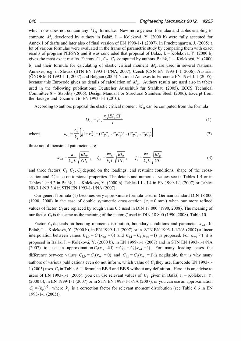
Tab. 1: Values of factors 1C and 3C corresponding to various end moment ratios ψ , values of
buckling length factor zk and cross-section parameters fψ and wtκ .
End moment loading of the simply supported beam with buckling length factors 1=yk for major axis
bending and 1=wk for torsion
1) 1,1wt0,11,10,11 ≤) -(+= CκCCCC , ( 0,11 CC = for 0wt =κ , 1,11 CC = for 1wt ≥κ )
2) =L7,0 left end fixed, R7,0 = right end fixed
Kolekova Y., Balaz I. 641
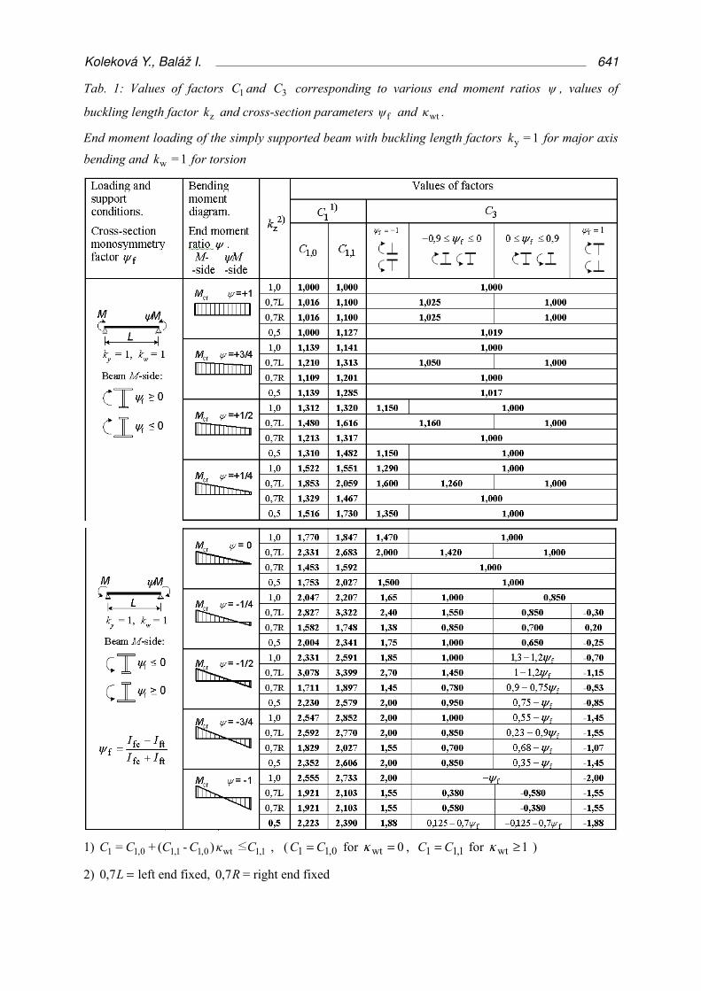
Tab. 2: Values of factors C1, C2 and C3 corresponding to various transverse loading cases, values of buckling length factors yk , zk , wk , cross-section monosymmetry factor fψ and torsion parameter
wtκ .
1) 1,1wt0,11,10,11 ≤) -(+= CκCCCC , ( 0,11 CC = for 0wt =κ , 1,11 CC = for 1wt ≥κ ).
2) Parameter fψ refers to the middle of the span.
3) Values of critical moments Mcr refer to the cross section, where Mmax is located
642 Engineering Mechanics 2012, #235

Tab. 3: Relative non-dimensional critical moment crμ for cantilever )2( wzy === kkk loaded by
concentrated tip load F .
a) For 0j =z , 0g =z and 8wt0 ≤κ : 2wt0wt0cr 017,014,127,1 κκμ ++= .
b) For 0j =z , 44 g ≤≤− ζ and 4wt ≤κ , crμ may be calculated also from formulae (I.7) and (I.8),
where the following approximate values of the factors 21 C,C should be used for the cantilever under tip load F:
3wt
2wtwt1 5,062,2675,456,2 κκκ +−+=C , if 2wt ≤κ
55,51 =C if 2wt >κ
4wt
3wt
2wtwt2 024,0245,0931,0566,1255,1 κκκκ −+−+=C , if 0g ≥ζ
g2wtwt
2wtwt2 )013,0102,0032,0(054,0585,0192,0 ζκκκκ −+−−+=C , if 0g <ζ
Kolekova Y., Balaz I. 643

Tab. 4: Relative non-dimensional critical moment crμ for cantilever )2( wzy === kkk loaded by
uniformly distributed load q
a) For 0j =z , 0=gz and 80 ≤wtκ : 200 021,068,204,2 wtwtcr κκμ ++= .
b) For 0j =z , 44 g ≤≤− ζ and 4wt ≤κ , crμ may be calculated also from formula (I.7) and (I.8),
where the following approximate values of the factors 21, CC should be used for the cantilever under uniform load q:
3wt
2wtwt1 975,065,52,1111,4 κκκ +−+=C , if 2wt ≤κ
121 =C if 2wt >κ
4wt
3wt
2wtwt2 014,0153,0609,0068,1661,1 κκκκ −+−+=C ,if 0g ≥ζ
g2wtwt
2wtwt2 )0085,0074,0061,0(029,0426,0535,0 ζκκκκ −+−−+=C , if 0g <ζ
644 Engineering Mechanics 2012, #235
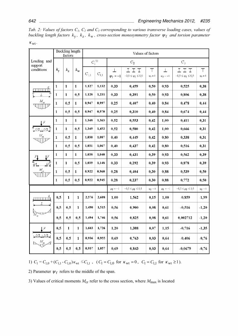
In this paper we give values of )235,0=( wt1 κC for a lot of new moment distributions valid for beam
supported at both ends by “forks”, with double symmetric cross-section, for which parameter 0=jζ
and there is no need to know value of 3C . These 1C values may be used also for continuous girders being on the safe side. Investigated loading case is shown in Figure 1.
Fig.1: Investigated loading case
The following was taken into account:
1≤≤1- ψ , 0≥8
1= 2
0 qLM , 0≤M , 0
22
0F 16
)-1(+
2
+1+=
M
MψM
ψMM (4)
MM =max if ( ) 1>4
+3-
2
+1
0M
MψMsign
ψ, otherwise Fmax = MM (5)
Elastic critical moment crM may be calculated from the formula (1) for cases 0=gζ . For cases
0≠gζ , because we have not relevant values of factor 2C for various cases, we can use an
approximate value 5,0=2C for all cases as it was done also in DIN 18 800 (1990, 2008). Then
[ ]g2
g2wt
z
1cr 5,0-)5,0(++1≈ ζζκ
k
Cμ (6)
The numerical values of factor 1C were calculated for 235,0=wtκ and different moment distributions
defined by parameters MMψ /, 0 by an efficient computer program CalcMcr Version 1.9 developed
by the authors and they may be used also for the beams with any wtκ values. 1C values were computed for combination of 21 end moments ratios ψ = -1; -0,9; -0,8; -0,7; -0,6; -0,5; -0,4; -0,3; -0,2; -0,1; 0;
0,1; 0,2; 0,3; 0,4; 0,5; 0,6; 0,7; 0,8; 0,9; 1, and 11 moment ratios MM /0 = 0; - 0,25; - 0,5; - 0,75; - 1; -
1,25; - 1,5; - 1,75; - 2; -10; -∞ (see Table 5 and Figure 2). 16,1≈1C for MM /0 = - 10 and 13,1=1C
for ∞-=/0 MM for all ψ values. Similar table as Table 5 was created also for ∞≤/≤0 0 MM , but
it is not given here because of limited size of the paper. Location of the elastic critical moment crM is
identical with location of maximum moment maxM .
Similar tables like Table 1 were created also for four other loadings and boundary conditions:
(i) point load F in the middle of the beam span combined with support moments,
(ii) two point loads F acting in quarters of the beam span combined with support moments,
(iii) cantilever under uniform loading q and
(iv) cantilever under tip load F .
L
q
M2
1⋅
ψ+
M M⋅ψ-
+ FM
0M
Kolekova Y., Balaz I. 645
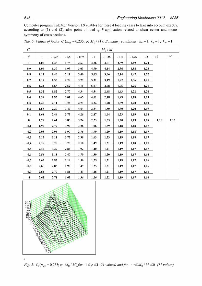
Computer program CalcMcr Version 1.9 enables for these 4 loading cases to take into account exactly, according to (1) and (2), also point of load Fq, application related to shear center and mono-symmetry of cross-sections.
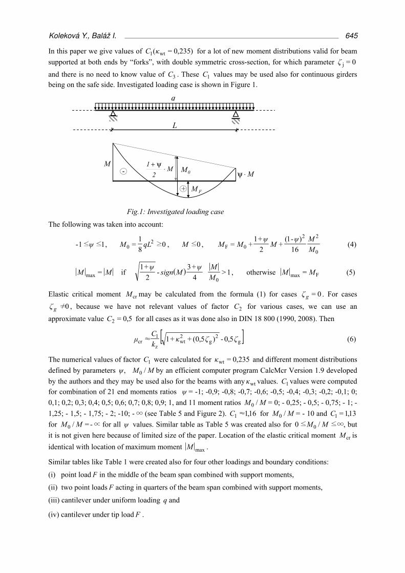
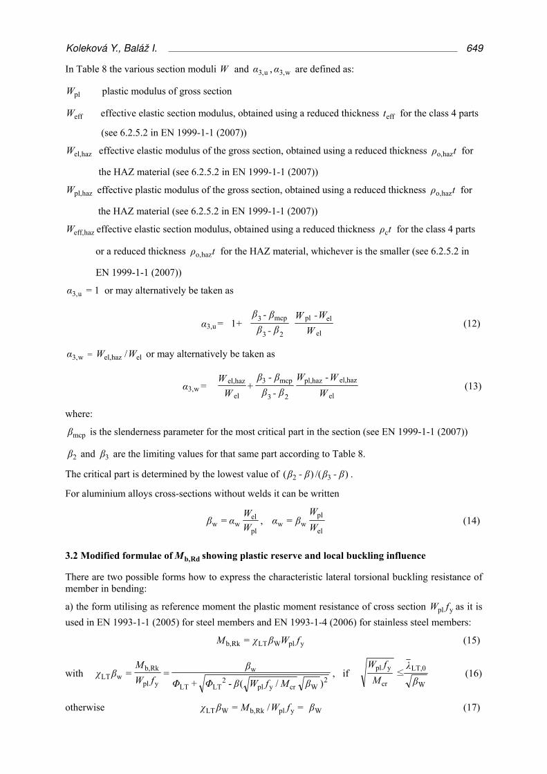
Tab. 5: Values of factor )/;;235,0=( 0wt1 MMψκC . Boundary conditions: 1=yk , 1=zk , 1=wk .
1C MM /0
ψ 0 - 0,25 - 0,5 - 0,75 - 1 - 1,25 - 1,5 - 1,75 - 2 -10 -∞
1 1,00 1,28 1,75 2,67 4,36 4,61 2,59 1,69 1,24
1,16 1,13
0,9 1,06 1,37 1,93 3,03 4,70 4,14 2,36 1,58 1,23
0,8 1,11 1,46 2,11 3,40 5,05 3,66 2,14 1,47 1,22
0,7 1,17 1,56 2,29 3,77 5,31 3,19 1,92 1,36 1,21
0,6 1,24 1,68 2,52 4,11 5,07 2,78 1,75 1,26 1,21
0,5 1.32 1,82 2,77 4,34 4,54 2,48 1,63 1,22 1,20
0,4 1,39 1,95 3,01 4,65 4,01 2,18 1,49 1,18 1,19
0,3 1,48 2,11 3,26 4,77 3,34 1,98 1,39 1,20 1,19
0,2 1,58 2,27 3,49 4,64 2,84 1,80 1,30 1,20 1,19
0,1 1,68 2,44 3,73 4,26 2,47 1,64 1,23 1,19 1,18
0 1,79 2,61 3,83 3,74 2,23 1,53 1,20 1,19 1,18
-0,1 1,90 2,79 3,99 3,26 1,96 1,39 1,18 1,18 1,17
-0,2 2,03 2,96 3,97 2,76 1,79 1,29 1,19 1,18 1,17
-0,3 2,15 3,11 3,75 2,38 1,63 1,23 1,19 1,18 1,17
-0,4 2,28 3,28 3,29 2,10 1,49 1,21 1,19 1,18 1,17
-0,5 2,40 3,27 2,84 1,92 1,40 1,21 1,19 1,17 1,17
-0,6 2,54 3,18 2,47 1,70 1,30 1,20 1,19 1,17 1,16
-0,7 2,65 2,93 2,19 1,56 1,25 1,21 1,19 1,17 1,16
-0,8 2,65 2,83 1,99 1,49 1,25 1,21 1,19 1,17 1,16
-0,9 2,64 2,77 1,81 1,43 1,26 1,21 1,19 1,17 1,16
-1 2,62 2,71 1,63 1,36 1,26 1,22 1,19 1,17 1,16
Fig. 2: )/;;235,0=( 0wt1 MMψκC for 1≤≤1- ψ (21 values) and for 0≤/≤∞- 0 MM (11 values)
C1
646 Engineering Mechanics 2012, #235

All above mentioned tables are more general containing both )0=(= wt10,1 κCC and
)1=(= wt11,1 κCC values, what enables to obtain more exact 1C value for any wtκ by using an
interpolation.
3. Design buckling resistance moment Rdb,M
The design buckling resistance moment Rdb,M as it is defined in Eurocodes is described in paragraph
3.1. After modifications of Eurocode formulae the influence of plastic reserve and local buckling may be shown. This is done in paragraph 3.2.
3.1 Rdb,M according to Eurocodes EN 1993-1-1 (2005), -1-4 (2006) and EN 1999-1-1 (2007)
A laterally unrestrained member subject to major axis bending should be verified against lateral-torsional buckling as follows
0,1≤Rdb,
Ed
M
M (7)
where EdM is the design value of the moment.
The characteristic Rkb,M and design Rdb,M buckling resistance moment of a laterally
unrestrained beam should be taken as
yyLTRkb, = fWχM , M1
Rkb,Rdb, =
γ
MM (8)
where yf is the yield strength (in EN 1999-1-1 (2007) symbol of is used),
M1γ is partial safety factor of material which may be defined in national annex. The recommended values are given in Table 6.
Tab. 6: Recommended values of partial factor M1γ
EN EN 1993-1-1 (2005) EN 1993-1-4 (2006) EN 1993-2 (2006) EN 1999-1-1 (2007)
M1γ 1,0 1,1 1,1 1,1
The value of reduction factor LTχ for lateral torsional buckling depends on relative slenderness λLT ,
and imperfection factor LTα
0,1≤ ,-+
1= LT2
LT2LTLT
LT χλβΦΦ
χ (9)
[ ] λβλλα = Φ 2LTLT,0LTLTLT +)-(+15,0 (10)
where 1=β in 6.3.2.2 and value 75,0=β is recommended in 6.3.2.3 of EN 1993-1-1 (2005), ( β may be changed in National Annex for rolled I-sections and equivalent I-sections in 6.3.2.3).
LTα is an imperfection factor depending on buckling curve and it is defined in Eurocodes (Table 7),
LT,0λ is the limit of the horizontal plateau (Table 7),
cr
yyLT =
M
fWλ is the relative slenderness, (11)
crM is the elastic critical moment for lateral torsional buckling (see paragraph 2.).
Kolekova Y., Balaz I. 647
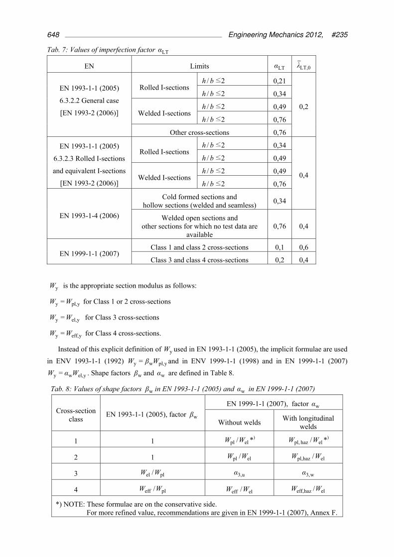
Tab. 7: Values of imperfection factor LTα
EN Limits LTα LT,0λ
EN 1993-1-1 (2005)
6.3.2.2 General case
[EN 1993-2 (2006)]
Rolled I-sections 2≤/ bh 0,21
0,2
2≤/ bh 0,34
Welded I-sections 2≤/ bh 0,49
2≤/ bh 0,76
Other cross-sections 0,76
EN 1993-1-1 (2005)
6.3.2.3 Rolled I-sections
and equivalent I-sections
[EN 1993-2 (2006)]
Rolled I-sections 2≤/ bh 0,34
0,4
2≤/ bh 0,49
Welded I-sections 2≤/ bh 0,49
2≤/ bh 0,76
EN 1993-1-4 (2006)
Cold formed sections and hollow sections (welded and seamless)
0,34
Welded open sections and other sections for which no test data are
available 0,76 0,4
EN 1999-1-1 (2007) Class 1 and class 2 cross-sections 0,1 0,6
Class 3 and class 4 cross-sections 0,2 0,4
yW is the appropriate section modulus as follows:
ypl,y = WW for Class 1 or 2 cross-sections
yel,y = WW for Class 3 cross-sections
yeff,y = WW for Class 4 cross-sections.
Instead of this explicit definition of yW used in EN 1993-1-1 (2005), the implicit formulae are used
in ENV 1993-1-1 (1992) ypl,wy = WβW and in ENV 1999-1-1 (1998) and in EN 1999-1-1 (2007)
yel,wy = WαW . Shape factors wβ and wα are defined in Table 8.
Tab. 8: Values of shape factors wβ in EN 1993-1-1 (2005) and wα in EN 1999-1-1 (2007)
Cross-section class
EN 1993-1-1 (2005), factor wβ
EN 1999-1-1 (2007), factor wα
Without welds With longitudinal
welds
1 1 elpl /WW *) elhaz pl, /WW *)
2 1 elpl /WW elhazpl, /WW
3 plel /WW u3,α w3,α
4 pleff /WW eleff /WW elhazeff, /WW
*) NOTE: These formulae are on the conservative side. For more refined value, recommendations are given in EN 1999-1-1 (2007), Annex F.
648 Engineering Mechanics 2012, #235
In Table 8 the various section moduli W and u3,α , w3,α are defined as:
plW plastic modulus of gross section
effW effective elastic section modulus, obtained using a reduced thickness efft for the class 4 parts
(see 6.2.5.2 in EN 1999-1-1 (2007))
hazel,W effective elastic modulus of the gross section, obtained using a reduced thickness tρ hazo, for
the HAZ material (see 6.2.5.2 in EN 1999-1-1 (2007))
hazpl,W effective plastic modulus of the gross section, obtained using a reduced thickness tρ hazo, for
the HAZ material (see 6.2.5.2 in EN 1999-1-1 (2007))
hazeff,W effective elastic section modulus, obtained using a reduced thickness tρc for the class 4 parts
or a reduced thickness tρ hazo, for the HAZ material, whichever is the smaller (see 6.2.5.2 in
EN 1999-1-1 (2007))
u3,α = 1 or may alternatively be taken as
1el
el pl
23
mcp3u3, W
W-W
β - β
β - β + = α (12)
w3,α = elhazel, /WW or may alternatively be taken as
el
hazel,hazpl,
23
mcp3
el
hazel,w3, W
W - W
β - β
β - β+
W
W = α (13)
where:
mcpβ is the slenderness parameter for the most critical part in the section (see EN 1999-1-1 (2007))
2β and 3β are the limiting values for that same part according to Table 8.
The critical part is determined by the lowest value of )/()( 32 β-ββ-β .
For aluminium alloys cross-sections without welds it can be written
pl
elww =
W
Wαβ ,
el
plww =
W
Wβα (14)
3.2 Modified formulae of Rdb,M showing plastic reserve and local buckling influence
There are two possible forms how to express the characteristic lateral torsional buckling resistance of member in bending:
a) the form utilising as reference moment the plastic moment resistance of cross section ypl fW as it is
used in EN 1993-1-1 (2005) for steel members and EN 1993-1-4 (2006) for stainless steel members:
yplWLTRkb, = fWβχM (15)
with 2
Wcrypl2
LTLT
w
ypl
Rkb,wLT
)/(-+==
βMfWβΦΦ
β
fW
Mβχ , if
W
LT,0
cr
ypl≤
β
λ
M
fW (16)
otherwise WyplRkb,WLT =/= βfWMβχ (17)
Kolekova Y., Balaz I. 649
where [ ]2WcryplLT,0WcryplLTLT )/(+)-/(+15,0= βMfWβλβMfWαΦ (18)
with 1=wβ for class 1, 2, plelW /= WWβ for class 3 sections and plefW /= WWβ f for class 4
sections.
b) the form utilising as reference moment the elastic moment resistance of cross section yel fW as it is
used in EN 1999-1-1 (2007) for design of aluminium members:
yelWLTRkb, = fWαχM (19)
with 2
Wcryel2
LTLTyel
Rkb,wLT
)/(-+==
αMfWβΦΦ
α
fW
Mαχ w , if
W
LT,0
cr
yel≤
α
λ
M
fW (20)
otherwise WyelRkb,WLT =/= αfWMαχ (21)
where [ ]2WcryelLT,0WcryelLTLT )/(+)-/(+15,0= αMfWβλαMfWαΦ (22)
with elplw /= WWα for class 1, 2, 1=Wα for class 3 sections and eleffW /= WWα for class 4
sections.
This modification may be done for formulae of all methods defining lateral buckling curves used in EN 1993-1-1 (2005): (i) general case in 6.3.2.2, with or without utilising 6.3.2.2(4), which means
that 1=LTχ in interval LT,0LT ≤≤0 λλ , (ii) rolled I-sections or equivalent welded sections in 6.3.2.3
with or without utilising factor f defined in 6.3.2.3(2).
According to 6.3.2.3(2) of EN 1993-1-1 (2005) the design buckling resistance moment may be increased by dividing by factor f , which may be defined in National Annex. The following minimum values are recommended in EN 1993-1-1 (2005):
[ ]2WcryplcWcryplc )8,0-/(2-1)-1(5,0-1=)/,( βMfWkβMfWkf (23)
but 0,1≤)/,( Wcryplc βMfWkf (24)
The factor f defined by (23) is smaller than 1 only in the interval
[ ] [ ] 5,1≈5,0+8,0≤/≤5,0+8,0;max≈1,0;max WcryplLT,0LT,0 βMfWλλ (25)
The correction factor ck for different moment distributions is given in Table 9a and in Table 6.6 in EN 1993-1-1 (2005)). In corrigendum EN 1993-1-1 (2005) from April 2009 it is recommended to use
ck values for calculation of 1C values used in EN 1993-1-1 (2005) in Table A.1, formulae BB.5 and
BB.9. The comparisons in Table 9b show that 1C values calculated from ck values are only
approximate ones. It is better to use more exact 1C values of authors published in Baláž, I. – Koleková, Y. (2000 b), in EN 1999-1-1 (2007) or in STN EN 1993-1-1/NA (2007).
It is very important to mention that all ck values compared in Table 9b relate to the cross-section
in the middle of the span and they are valid for boundary conditions 1=zk (both beam ends are
restrained against lateral movement and free to rotate in plan) and 1=wk (both beam ends are restrained against rotation about longitudinl axis and free to warp).
650 Engineering Mechanics 2012, #235

Tab. 9a: ck from EN 1993-1-1 (2005) Tab. 9b: Comparison of 1C values of authors with 2-ck
*) Values 2,576 and 2,608 relate to maxM and 0,9, 1,235, 1,288 and 1,304 relate to M in midspan
Distribution of modified lateral torsional buckling curves defined in 6.3.2.2 with utilising 6.3.2.2(4) is
shown in Fig.3. The ends of plateaux are denoted by relative slenderness values 4.0=LT,0λ ,
434,0==85.0/LT,0 eλ and 478,0==7.0/LT,0 fλ (Fig.3). Note the discrepancies in member
resistances ( plel > MM ) at these points when 6.3.2.2(4) is utilised.
Fig. 3: Functions )/(= cryplWLT MfWfβχ based on EN 1993-1-1 (2005), 6.3.2.2 calculated for
imperfection factor 76,0=LTα , relative slenderness defining end of the plateau 4,0=LT,0λ , 1=β
and for (i) 1=wβ (black dashed line), (ii) 85,0=/= plelw WWβ (red solid line) and (iii)
7,0=/= pleffw WWβ (blue dot-and-dashed line). Plastic reserve of member is defined by the
ordinates of the bottom black dotted line, which should be multiplied by 100 to obtain plastic reserve in %.
Kolekova Y., Balaz I. 651
4. Conclusions
The paper is devoted to (i) critical moment crM and (ii) lateral torsional buckling resistance moment
Rdb,M of metal (steel and aluminium) beams.
The original results of the authors are presented concerning calculation of crM by using approximate formulae convenient for standardization and educational purposes and for engineering practice. The results are based on large parametrical studies (Baláž, I., 1999-2001, 2005, 2007, Baláž, I. – Koleková, Y., 1999-2001, 2002, Koleková, Y., 1999) which showed that procedure used in prestandard Eurocodes ENV 1993-1-1 (1992) and ENV 1999-1-1 (1998) may lead in many cases to incorrect results. Authors results, which were the first time published in (Baláž, I. – Koleková, Y., 1999 a, b, 2000 b, c, 2002 a, b) are today used in many international and national standardization documents including Eurocodes (Belgian National Annex, 2005, Czech National Annex ČSN EN 1993-1-1, 2006, Austrian National Annex ÖNORM B 1993-1-1, 2007, Slovak National Annex STN EN 1993-1-1/NA, 2007, Design Manual For Structural Stainless Steel, 2006, Deutscher Ausschluß für Stahlbau, 2005, ECCS Technical Committee 8 – Stability, 2006, Excerpt from the Background Document to EN 1993-1-1, 2010, EN 1999-1-1, 2007). The correctness and the exactness of results based on authors results (Table 1-4) were verified in habilitation thesis (Koleková, Y., 1999) and later also in two independent Brazilian and Slovak PhD thesis (Fruchtengarten, J., 2005, Živner, T., 2010). The Brazilian PhD thesis stated that crM values calculated on the basis of the authors results are the
best among all used approximate formulae. Procedure of crM calculation based on authors results were introduced in the engineering practice of many countries. In Slovakia it was thanks to courses for the engineers in practice organized by Universities and Slovak Chamber of Civil Engineers and the textbooks written for them (Baláž, I., 2007, 2010, 2012) and for the university students. It was also showed how the procedure used for many years in Czechoslovak, Czech and Slovak standards may be improved (Baláž, I., 1980, 1997, 1998, 2000), Baláž, I. – Živner, T., 2007). The detailed numerical examples were published in the above mentioned textbooks and in the several papers (e.g. Baláž, I. (2012). The authors created for engineers in practice and for students at Universities the original computer program CalcMcr.
New 1C values derived by authors for uniform loading combined with end moments are presented in Table 5 and Figure 2.
The Table 9a, b shows that using of ck values recommended in corrigendum EN 1993-1-1 (2005)
from April 2009 for calculation of 1C values may lead to approximate values, which may be used in
correct way only if user knows that: (i) relating boundary conditions are 1=zk (both beam ends are
restrained against lateral movement and free to rotate in plan) and 1=wk (both beam ends are
restrained against rotation about longitudinal axis and free to warp and that (ii) ck values compared in
Table 9b with authors more exact 1C values are valid for M in midspan and not to cross-section were
maxM is located.
The paper presents also the way how the Eurocode formulae (EN 1993-1-1, 2005), EN 1993-1-4, 2006), EN 1999-1-1, 2007) for calculation of lateral torsional buckling resistance Rdb,M may be
modified to show clearly influence of plastic reserve and local buckling on beam resistance (paragraph 3.2 and Figure 3). This may be very useful for engineers in practice. The much more similar diagrams as it is on Figure 3 were published in (Baláž, I. – Koleková, Y., 2007, 2008, 2009).
The paper is devoted to the lateral torsional buckling resistance of metal (steel, stainless steel, aluminium) beams, but the presented results may be used also for design and verification of structures made of other structural materials (timber, concrete, composite steel and concrete structures). The results relating to lateral torsional buckling of: (i) timber beams authors solved in the papers (Baláž, I., 2001, 2005, Baláž, I. – Koleková, Y., 2004 a, b), (ii) concrete beams in (Baláž, I. – Živner, T., 2006), (iii) aluminium beams in (Baláž, I. – Valach, P., 1997, Baláž, I. – Koleková, Y. – Ároch, R., 1998, Baláž, I. – Koleková, Y., 2000 a, 2007, 2008). The influence of beam end stiffeners was solved in (Živner, T., 2010, Živner, T. – Baláž, I., 2010).
652 Engineering Mechanics 2012, #235
The second author is the member of 5 working Evolution Groups: EG EN 1993-1-1, EG EN 1993-1-3, EG EN 1993-1-5, EG EN 1993-2 and EG EN 1999-1-1. All members of EGs are very active without any financial support on the European level. Even accommodation, travel, food and other expenses must be covered by own budget of EGs members. EGs are responsible for maintenance of existing Eurocodes (creating of Corrigenda and Amendments) and for further development of the next generation of Eurocodes. Nobody else from Slovak republic is member of EGs.
We spent blessed moments in investigation of these problems during several years despite of the fact that financial support was very poor. The reasons of poor funding were: a) the funding into the science in Slovakia is for long time deeply undersized comparing with all other EU countries, b) only the results published in current journals are highly evaluated even when they are without any useful application, c) journals with high impact factors are preferred despite of the fact that the European Association of Science Editors already in November 2007 issued an official statement recommending "that journal impact factors are used only – and cautiously – for measuring and comparing the influence of entire journals, but not for the assessment of single papers, and certainly not for the assessment of researchers or research programs", d) a well known specialist from the Institute of Construction and Architecture, Slovak Academy of Sciences in Bratislava evaluated our first grant application for this project in 1999 and in his review he gave us the lowest possible grades and used the following wordings: “investigators – underaverage; scientific team composition – inadequate; expected contributions – not important; scientific goals – obsolete, everything was already solved”.
Acknowledgement The authors acknowledge support by the Slovak Scientific Grant Agency under the contracts No. 1/1101/12.
References
Baláž, I. (1980) Klopenie nosníkov v zmysle revidovanej ČSN 73 1401. Staveb. Čas. 28, č.6, VEDA, Bratislava, s. 465-478.
Baláž, I. (1997) Comparison of Different Design Curves for Lateral Torsional Buckling of Rolled and Welded Steel Beams, in: Proc. of 18th Czecho-Slovak International Conference on Steel Structures and Bridges `97 . Brno, p. 2 / 3 – 2 / 11.
Baláž, I. (1998) Klopenie nosníkov podľa STN 73 1401: 1997, in: Zborník prednášok z konferencie „Súčasný stav európskych a slovenských technických noriem a ich aplikácie v stavebníctve.“ SvF TU Košice. Košice, s. 41-48.
Baláž, I. (1999 a) Buckling of monosymmetric beams – conjured problem, in: Proc. Eurosteel 2nd European Conference on Steel Structures, Praha, pp.701-704.
Baláž, I.: (1999 b) Kritické momenty pri klopení podľa STN 73 1401, in: Zborník prednášok z XXV. Celoštátneho aktívu „Stratégia rozvoja oceľových konštrukcií.“ Lipovce, s.77-82.
Baláž, I. (1999 c) Klopenie kovových nosníkov, in: Zborník XI. Mezinárodní vědecké konference. VUT Brno, s. 63-66.
Baláž, I. (2000) Kapitola 6.8.2 “Prúty namáhané ohybom“ str.104 – 112 a „Príloha H“ str. 235 – 250. in: P. Juhás a kol.: Navrhovanie oceľových konštrukcií. Komentár k STN 73 1401: 1998. SÚTN Bratislava, str. 1 – 260. ISBN 80-88971-06-3.
Baláž, I. (2001) Klopenie drevených nosníkov, in: Zborník prednášok z konferencie „Výstavba a obnova budov“, výstava PRO DOMO. Košice. Dom techniky Košice, s. 27-32.
Baláž, I. (2005) Lateral torsional buckling of timber beams. Wood Research, 50(1), pp.51-58.
Baláž, I. (2007 a) Klopenie nosníkov v STN EN 1993-1-1 a EN 1999-1-1. in: Zborník odborných prednášok, 1. časť. ESF SÚTN Nové európske normy na navrhovanie kovových konštrukcií – Eurokód 3 a 9. STU Bratislava. S. 84 – 94 a in: Zborník odborných prednášok, 2.časť, s. 1 – 8.
Baláž, I. (2007 b) Kapitola 6: Klopenie ohýbaných nosníkov. Prúty namáhané kombinovane osovou silou NEd a ohybovým momentom MEd podľa STN EN 1993-1-1 In: Zborník SKSI: Baláž, I. – Ároch, R. – Chladný, E. –Kmeť, S. – Vičan, J.: Navrhovanie oceľových konštrukcií podľa Eurokódov STN EN 993-1-1: 2006 a STN EN 1993-1-8: 2007. Bratislava, s.96-131.
Baláž, I. (2010) Kapitola 6: Klopenie ohýbaných nosníkov. Prúty namáhané kombinovane osovou silou NEd a ohybovým momentom MEd podľaSTN EN 1993-1-1 In: Zborník SKSI: Baláž, I. – Ároch, R. – Chladný, E. – Kmeť, S. – Vičan, J.: Navrhovanie oceľových konštrukcií podľa EurokódovSTN EN 1993, časti -1-1:2006 a
Kolekova Y., Balaz I. 653
-1-8: 2007, podľa ich národných príloh NA: 2007 a NA: 2008 a ich opráv AC: 2009 a AC: 2009.Bratislava, s.107-267.
Baláž, I. (2012) Klopenie kovových nosníkov aj podĺa eurokódov, in: Zborník 17. konferencie statikov “Statika stavieb 2012”, Piešťany, s.7-20.
Baláž, I., Koleková, Y. (1999 a) Buckling of monosymmetric beams – conjured problem, in: CD-ROM 2nd part. Eurosteel 2nd European Conference on Steel Structure, Praha, 21 pages.
Baláž, I., Koleková, Y. (1999 b) Stability of monosymmetric beams, in: Proc. of the 6th International Colloquium “Stability and ductility of steel structures” , Timisoara, pp.57-64.
Baláž, I., Koleková, Y. (2000 a) Lateral Torsional Buckling of Unwelded and Welded Steel and Aluminium Beams. Slovak Journal of Civil Engineering. 2000/3, pp.1-7.
Baláž, I., Koleková, Y. (2000 b) Proposals for Improvements of Lateral Torsional Buckling Eurocodes Rules, in: Proc. of 19th Czech and Slovak International Conference “Steel Structures and Bridges 2000”. Štrbské Pleso, High Tatras, pp.81-86.
Baláž, I., Koleková, Y. (2000 c) Critical Moments of Beams and Girders. Clark – Mrázik formula, in: Proc. of 19th Czech and Slovak International Conference “Steel Structures and Bridges 2000”. Štrbské Pleso, High Tatras, pp.87-94.
Baláž, I., Koleková, Y. (2000 d) Klopenie nosníkov a konzol podľa noriem STN 73 1401 a ČSN 73 1401. Analýza a návrhy na vylepšenie, in: Zborník XXVI. celoštátneho aktívu pracovníkov odboru oceľových konštrukcií: “Kovové konštrukcie a mosty. Súčasný stav a prespektívy rozvoja.” SvF ŽU Žilina, SSOK ZSVTS Bratislava. Rajecké Teplice, pp.13-18.
Baláž, I., Koleková, Y. (2000 e) Besselove funkcie použité pri výpočte Mcr konzoly obdĺžnikového prierezu zaťaženej silou F, in: Zborník XXVI. celoštátneho aktívu pracovníkov odboru oceľových konštrukcií: “Kovové konštrukcie a mosty. Súčasný stav a prespektívy rozvoja.” SvF ŽU Žilina, SSOK ZSVTS Bratislava. Rajecké Teplice, pp.19-24.
Baláž, I., Koleková, Y. (2002 a) Critical Moments, in: Proc. of Internal Colloquium on Stability and Ductility of Steel Structures, Budapest, pp.31-38.
Baláž, I., Koleková, Y. (2002 b) Clark-Mrázik Formula for Critical Moments, in: Proc. of Internal Colloquium on Stability and Ductility of Steel Structures, Budapest, pp.39-46.
Baláž, I., Koleková, Y. (2004 a) Factors C1, C2, C3 for computing elastic critical moments Mcr, in: Zborník VI. sympózia Drevo v stavebných konštrukciách so zahraničnou účasťou. Kočovce, pp.29-34.
Baláž, I., Koleková, Y. (2004 b) Resistance of timber beams to out-of-plane buckling, in: Zborník VI. sympózia Drevo v stavebných konštrukciách so zahraničnou účasťou, Kočovce, pp.35-42.
Baláž, I., Koleková, Y. (2007) Lateral torsional buckling of beams, resistances and critical moments, in: Proc. Hommages à René Maquoi, Liège, pp.39-50.
Baláž, I., Koleková, Y. (2008) Odolnosť nosníkov z hliníkových zliatin a ocele v klopení, in: CD zborník príspevkov z Medzinárodnej vedeckej konferencie SvF STU. Bratislava, sekcia 02, blok D, príspevok č.25, str.1-8.
Baláž, I., Koleková, Y. (2009) Interesting results obtained by modifying of Eurocode formulae for stability of members. Sborník: 22. Česká a slovenská konference. Ocelové konstrukce a mosty 2009. AN CERM, Brno, s. 7-14.
Baláž, I., Koleková, Y., Ároch, R. (1998) Lateral Torsional Buckling of Unwelded and Welded Steel and Aluminium Beams. Second World Conference on Steel in Construction. San Sebastián 11-13, poster.
Baláž, I. - Plačko, B. (1980) Posudzovanie nosníkov na klopenie. Technický zpravodaj OK. Příloha - pomůcky a směrnice. VŽSKG Ostrava, č.3, s.1-51.
Baláž, I., Valach, P. (1997) Lateral Torsional Buckling of Unwelded Aluminium Beams, in: Zborník prednášok zo VI. vedeckej konferencie SvF TU v Košiciach. 8. sekcia. Kovové a drevené konštrukcie. Košice, s.87-92.
Baláž, I., Živner, T. (2006) LTB of Unrestrained Steel Beams According to EN 1993-1-1 and Positive Influence of Metal Sheeting Acting as Shear Diaphragm, in: Zborník prednášok 21. českej a slovenskej medzinárodnej konferencie. Bratislava, KKDK SvF STU Bratislava, s.117-126.
Baláž, I., Živner, T. (2007) Kritické ohybové momenty obojstranne votknutých nosníkov v článku H.2 normy STN 73 1401: 1998, in: Zborník VIII. Vedeckej konferencie s medzinárodnou účasťou. Stavebná fakulta TU Košice, s.19-24.
Belgian National Annex (2005) for the EN 1993 Part 1-1 IBN Committee „Steel Structures“. Version 28.10.2005.
ČSN EN 1993-1-1 (2006) Eurokód 3: Navrhování ocelových konstrukcí – Část 1-1: Obecná pravidla a pravidla pro pozemní stavby Národní příloha NB (informativní), pp.95-98.
654 Engineering Mechanics 2012, #235

Design Manual For Structural Stainless Steel. (2006), 3rd edition. Appendix B: Lateral torsional buckling. Euro Inox and SCI, pp. 109-112.
Deutscher Ausschluß für Stahlbau (2005). Out-of-plane stability of plane structural frames. Baláž, I. – Koleková, Y.: Annex 1. Design aid to determining the elastic critical moments Mcr for lateral torsional buckling. Aachen, pp.14-29.
DIN 18 800 (1990) Stahlbauten. Teil 2 Stabilitätsfälle, Knicken von Stäben und Stabwerken. DIN, Beuth, Berlin.
DIN 18 800 (2008) Stahlbauten. Teil 2 Stabilitätsfälle, Knicken von Stäben und Stabwerken. DIN, Beuth, Berlin.
ECCS Technical Committee 8 – Stability (2006) Rules for Member Stability EN 1993-1-1. Background documentation and design guidelines. No.119. Brussels, 259 pages.
EN 1993-1-1 (2005) Eurocode 3: Design of Steel Structures. Part 1-1: General Rules and Rules for Buildings CEN Brussels.
EN 1994-1-1 (2004) Eurocode 3: Design of Composite Steel and Concrete Structures. Part 1-1: General Rules and Rules for Buildings CEN Brussels.
EN 1995-1-1 (2004) Eurocode 3: Design of Timber Structures. Part 1-1: General Rules and Rules for Buildings CEN Brussels.
EN 1999-1-1 (2007) Eurocode 9: Design of Aluminium Structures. Part 1-1: General Structural Rules. CEN Brussels.
ENV 1993-1-1 (1992) Eurocode 3: Design of Steel Structures. Part 1-1: General Rules and Rules for Buildings CEN Brussels.
ENV 1999-1-1 (1998) Eurocode 9: Design of Aluminium Structures. Part 1-1: General Rules and Rules for Buildings CEN Brussels.
Excerpt from the Background Document to EN 1993-1-1 (2010) Baláž, I., Koleková, Y.: Chapter 7.2 Design Aids. 7.2.1 Hand formulae for the determination of Mcr. Flexural buckling and lateral torsional buckling on a common basis: Stability assessments according to Eurocode 3. Stahlbau Leichtmetallbau. Aachen, pp.60-67.
Fruchtengarten, J. (2005) Sobre o estudo da flambagem lateral de vigas de aço por meio da utilizaçoã de uma teoria não-linear geometricamente exata, Dissertação (Mestrado), Departamento de Engenharia de Estruturas e Fundações, Escola Politécnica da Universidade de São Paulo. São Paulo, 226 pages.
Hirt, M.A., Bez, R. (1998) Stahlbau. Grundbegriffe und Bemessungsverfahren, 1st German Edition, Ernst & Sohn, A Wiley Company, Berlin.
Hirt, M.A., Bez, R., Nussbaumer, A. (2007) Stahlbau. Grundbegriffe und Bemessungsverfahren, 2nd German Edition, Ernst & Sohn, A Wiley Company, Berlin.
Koleková, Y. (1999) Elastic Critical Moments of the Thin-Walled Beams with Monosymmetric Cross-Section. (In Slovak). Thesis for docent habilitation. Faculty of Civil Engineering. Slovak University of Technology. Bratislava, 121 pages.
ÖNORM B 1993-1-1 (2007) Eurocode 3: Bemessung und Konstruktion von Stahlbauten. Teil 1-1: Allgemeine Bemessungsregeln. Nationale Festlegungen zu ÖNORM EN 1993-1-1, nationale Erläuterungen und nationale Ergänzungen. Ausgabe 2007-02-01. Wien.
Roik, K., Carl, J., Lindner, J. (1972) Biegetorsionsprobleme gerader dünnwandiger Stäbe. Berlin, München, Düssledorf. Ernst & Sohn, 252 pages.
STN EN 1993-1-1/NA (2007) Navrhovanie oceľových konštrukcií. Časť 1-1: Všeobecné pravidlá a pravidlá pre budovy. Národná príloha. S.1-24. SÚTN Bratislava.
STN EN 1999-1-1 + A1 (2011). Navrhovanie hliníkových konštrukcií. Časť 1-1: Všeobecné pravidlá pre konštrukcie. Preklad európskej normy. S.1-220. SÚTN Bratislava.
Živner, T., Baláž, I. (2010) Vplyv čelnej dosky na klopenie nosníkov, in: Zborník 36.aktívu pracovníkov odboru oceľových konštrukcií. Oceľové, drevené a kompozitné konštrukcie a mosty. Hotel Boboty,Terchová – Vrátna. ŽU v Žiline, SSOK. Str. 25-32.
Živner, T. (2010) Stabilitné problémy ohýbaných nosníkov. PhD Thesis. STU v Bratislave, pp.1-228.
Kolekova Y., Balaz I. 655