Embed Size (px)
Citation preview
Localized buckling in sandwich struts with inhomogeneous
deformations in both face plates
Stylianos Yiatrosa,b,∗, Orestes Marangosa, M. Ahmer Wadeec, Christodoulos Georgioua
aDepartment of Civil Engineering & Geomatics, Cyprus University of Technology 3036, Limassol,Cyprus.
bCentre of Offshore Renewable Energy, Cranfield University, MK43 0AL, UK.cDepartment of Civil & Environmental Engineering, Imperial College of Science Technology and
Medicine, South Kensington Campus, SW7 2AZ, UK.
Abstract
A nonlinear analytical model for investigating localized interactive buckling in simply sup-ported thin-face plate sandwich struts with weak cores is extended to account for localdeformations in both face plates, which have been observed in experiments and finite el-ement simulations. The original model is based on potential energy principles with largedisplacement assumptions. It assumes Timoshenko shear deformable theory for the coreand approximates the overall mode as a half-sine wave along the length of the strut whilethe local face plate displacements are initially unknown and are found as solutions of thegoverning equations. The extended model is able to capture measurable local face platedisplacements in the less compressed face plate, beyond the secondary bifurcation whichleads to localized interactive buckling, for the case where overall buckling is critical. More-over, the allowance of local displacements in both face plates allows the extended modelto predict the post-buckling behaviour better in cases where local buckling is critical. Theresults from this model compare very well with nonlinear finite element simulations withrespect to both the equilibrium paths and panel deformations.
Keywords: Mode interaction, Sandwich struts, Variational formulation, Interactivebuckling, Post-buckling
1. Introduction
Sandwich construction is well-known in many engineering disciplines as a versatile struc-tural solution with a favourable combination of low weight and high bending stiffness [1].Such structures usually comprise two stiff thin plates separated by a soft compliant core.By positioning the stiff plates away from one another increases the bending rigidity of thesandwich structure, while the compliant core is able to resist shear stresses. This opti-mized configuration, however, is prone to instability phenomena such as overall buckling
∗Corresponding authorEmail address: [email protected] (Stylianos Yiatros)
Preprint submitted to Composite Structures July 23, 2015
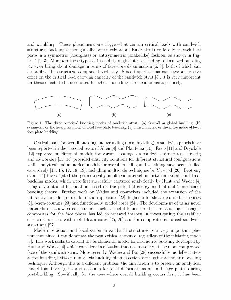
and wrinkling. These phenomena are triggered at certain critical loads with sandwichstructures buckling either globally (effectively as an Euler strut) or locally in each faceplate in a symmetric (hourglass) or antisymmetric (snake-like) fashion, as shown in Fig-ure 1 [2, 3]. Moreover these types of instability might interact leading to localized buckling[4, 5], or bring about damage in terms of face–core delamination [6, 7], both of which candestabilize the structural component violently. Since imperfections can have an erosiveeffect on the critical load carrying capacity of the sandwich strut [8], it is very importantfor these effects to be accounted for when modelling these components properly.
(a) (b) (c)
Figure 1: The three principal buckling modes of sandwich strut. (a) Overall or global buckling; (b)symmetric or the hourglass mode of local face plate buckling; (c) antisymmetric or the snake mode of localface plate buckling.
Critical loads for overall buckling and wrinkling (local buckling) in sandwich panels havebeen reported in the classical texts of Allen [9] and Plantema [10]. Fazio [11] and Drysdale[12] reported on different models for various loadings on sandwich structures. Frostigand co-workers [13, 14] provided elasticity solutions for different structural configurationswhile analytical and numerical models for overall buckling and wrinkling have been studiedextensively [15, 16, 17, 18, 19], including multiscale techniques by Yu et al [20]. Leotoinget al [21] investigated the geometrically nonlinear interaction between overall and localbuckling modes, which were first succesfully captured analytically by Hunt and Wadee [4]using a variational formulation based on the potential energy method and Timoshenkobending theory. Further work by Wadee and co-workers included the extension of theinteractive buckling model for orthotropic cores [22], higher order shear deformable theories[5], beam-columns [23] and functionally graded cores [24]. The development of using novelmaterials in sandwich construction such as metal foams for the core and high strengthcomposites for the face plates has led to renewed interest in investigating the stabilityof such structures with metal foam cores [25, 26] and for composite reinforced sandwichstructures [27].
Mode interaction and localization in sandwich structures is a very important phe-nomenon since it can dominate the post-critical response, regardless of the initiating mode[8]. This work seeks to extend the fundamental model for interactive buckling developed byHunt and Wadee [4] which considers localization that occurs solely at the more compressedface of the sandwich strut. More recently, Wadee and Bai [28] successfully modelled inter-active buckling between minor axis buckling of an I-section strut, using a similar modellingtechnique. Although this is a different problem, the aim herein is to present an analyticalmodel that investigates and accounts for local deformations on both face plates duringpost-buckling. Specifically for the case where overall buckling occurs first, it has been
2
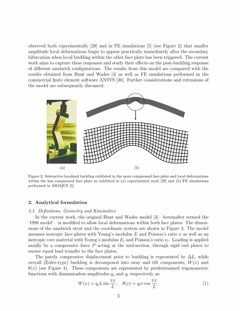
observed both experimentally [29] and in FE simulations [5] (see Figure 2) that smalleramplitude local deformations begin to appear practically immediately after the secondarybifurcation when local buckling within the other face plate has been triggered. The currentwork aims to capture these responses and study their effects on the post-buckling responseof different sandwich configurations. The results from this model are compared with theresults obtained from Hunt and Wadee [4] as well as FE simulations performed in thecommercial finite element software ANSYS [30]. Further considerations and extensions ofthe model are subsequently discussed.
(a) (b)
Figure 2: Interactive localized buckling exhibited in the more compressed face plate and local deformationswithin the less compressed face plate as exhibited in (a) experimental work [29] and (b) FE simulationsperformed in ABAQUS [5].
2. Analytical formulation
2.1. Definitions, Geometry and Kinematics
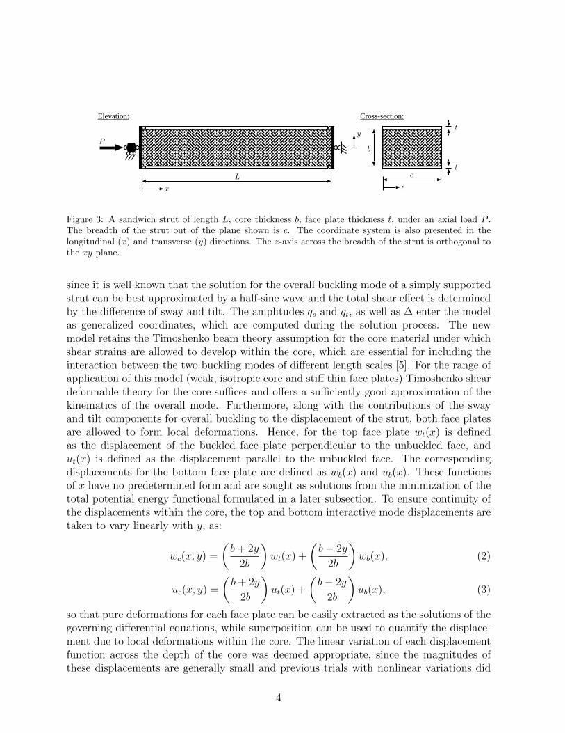
In the current work, the original Hunt and Wadee model [4]—hereinafter termed the‘1998 model’—is modified to allow local deformations within both face plates. The dimen-sions of the sandwich strut and the coordinate system are shown in Figure 3. The modelassumes isotropic face plates with Young’s modulus E and Poisson’s ratio ν as well as anisotropic core material with Young’s modulus Ec and Poisson’s ratio νc. Loading is appliedaxially by a compressive force P acting at the mid-section, through rigid end plates toensure equal load transfer to the face plates.
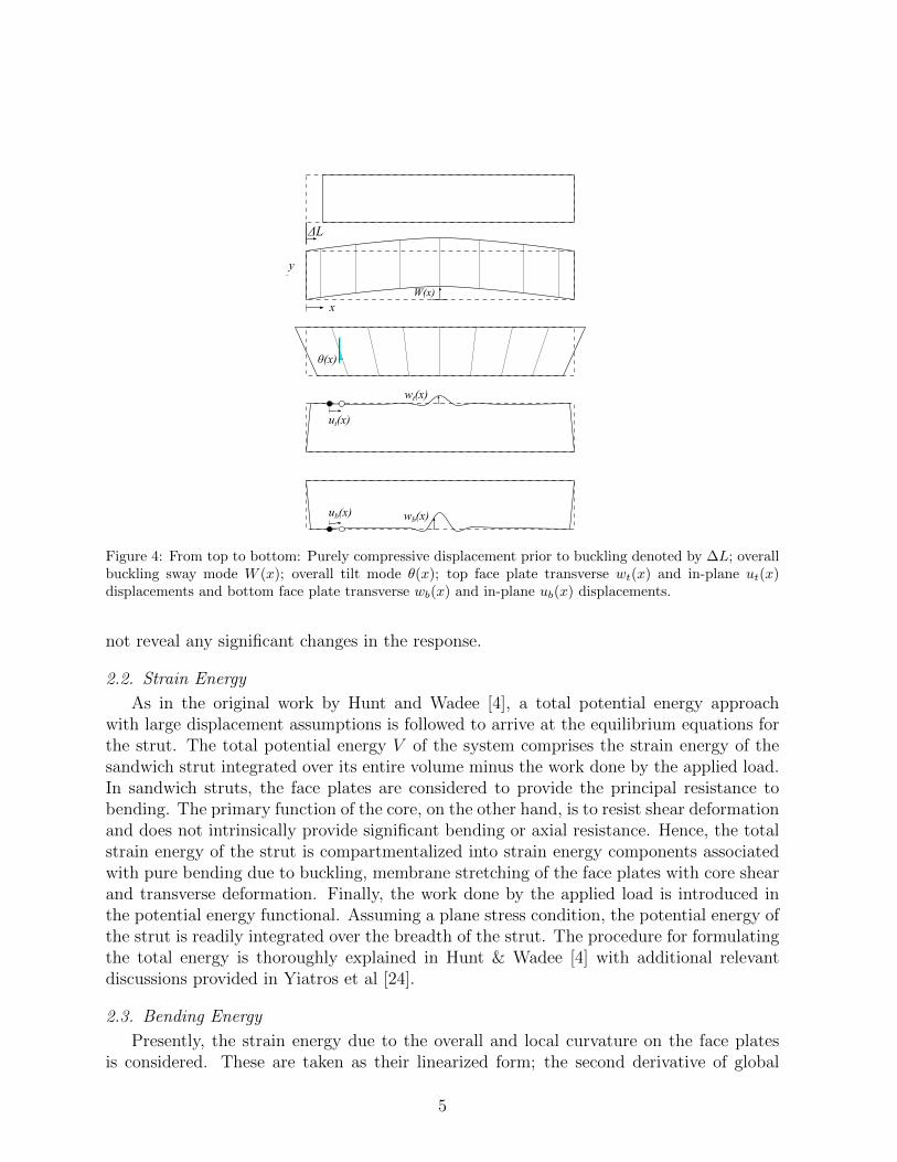
The purely compressive displacement prior to buckling is represented by ∆L, whileoverall (Euler-type) buckling is decomposed into sway and tilt components, W (x) andθ(x) (see Figure 4). These components are represented by predetermined trigonometricfunctions with dimensionless amplitudes qs and qt respectively as:
W (x) = qsL sinπx
L, θ(x) = qtπ cos
πx
L, (1)
3
t
t
x
Py
z
b
cL
Elevation: Cross-section:
Figure 3: A sandwich strut of length L, core thickness b, face plate thickness t, under an axial load P .The breadth of the strut out of the plane shown is c. The coordinate system is also presented in thelongitudinal (x) and transverse (y) directions. The z-axis across the breadth of the strut is orthogonal tothe xy plane.
since it is well known that the solution for the overall buckling mode of a simply supportedstrut can be best approximated by a half-sine wave and the total shear effect is determinedby the difference of sway and tilt. The amplitudes qs and qt, as well as ∆ enter the modelas generalized coordinates, which are computed during the solution process. The newmodel retains the Timoshenko beam theory assumption for the core material under whichshear strains are allowed to develop within the core, which are essential for including theinteraction between the two buckling modes of different length scales [5]. For the range ofapplication of this model (weak, isotropic core and stiff thin face plates) Timoshenko sheardeformable theory for the core suffices and offers a sufficiently good approximation of thekinematics of the overall mode. Furthermore, along with the contributions of the swayand tilt components for overall buckling to the displacement of the strut, both face platesare allowed to form local deformations. Hence, for the top face plate wt(x) is definedas the displacement of the buckled face plate perpendicular to the unbuckled face, andut(x) is defined as the displacement parallel to the unbuckled face. The correspondingdisplacements for the bottom face plate are defined as wb(x) and ub(x). These functionsof x have no predetermined form and are sought as solutions from the minimization of thetotal potential energy functional formulated in a later subsection. To ensure continuity ofthe displacements within the core, the top and bottom interactive mode displacements aretaken to vary linearly with y, as:
wc(x, y) =
(b+ 2y
2b
)wt(x) +
(b− 2y
2b
)wb(x), (2)
uc(x, y) =
(b+ 2y
2b
)ut(x) +
(b− 2y
2b
)ub(x), (3)
so that pure deformations for each face plate can be easily extracted as the solutions of thegoverning differential equations, while superposition can be used to quantify the displace-ment due to local deformations within the core. The linear variation of each displacementfunction across the depth of the core was deemed appropriate, since the magnitudes ofthese displacements are generally small and previous trials with nonlinear variations did
4
W(x)
ΔL
wb(x)
wt(x)
θ(x)
ut(x)
ub(x)
y
x
Figure 4: From top to bottom: Purely compressive displacement prior to buckling denoted by ∆L; overallbuckling sway mode W (x); overall tilt mode θ(x); top face plate transverse wt(x) and in-plane ut(x)displacements and bottom face plate transverse wb(x) and in-plane ub(x) displacements.
not reveal any significant changes in the response.
2.2. Strain Energy
As in the original work by Hunt and Wadee [4], a total potential energy approachwith large displacement assumptions is followed to arrive at the equilibrium equations forthe strut. The total potential energy V of the system comprises the strain energy of thesandwich strut integrated over its entire volume minus the work done by the applied load.In sandwich struts, the face plates are considered to provide the principal resistance tobending. The primary function of the core, on the other hand, is to resist shear deformationand does not intrinsically provide significant bending or axial resistance. Hence, the totalstrain energy of the strut is compartmentalized into strain energy components associatedwith pure bending due to buckling, membrane stretching of the face plates with core shearand transverse deformation. Finally, the work done by the applied load is introduced inthe potential energy functional. Assuming a plane stress condition, the potential energy ofthe strut is readily integrated over the breadth of the strut. The procedure for formulatingthe total energy is thoroughly explained in Hunt & Wadee [4] with additional relevantdiscussions provided in Yiatros et al [24].
2.3. Bending Energy
Presently, the strain energy due to the overall and local curvature on the face platesis considered. These are taken as their linearized form; the second derivative of global
5
and local lateral displacements, since the bending strains are small and the cross termsadd complexity to the formulation without changing the response significantly. The strainenergy from the local and global curvature is assembled, neglecting cross terms that playa negligible role in the total potential energy functional for a sandwich panel geometrywhere b� t and L� b or t� b and b� L:
Ub =1
2EI
∫ L
0
(2W ′′2 + w′′2t + w′′2b
)dx, (4)
where EI = Ect3/[12(1− v2)] and primes indicate differentiation with respect to x.
2.4. Membrane energy
Along with bending energy, face plates are also subjected to membrane action. Unlikethe previous model, axial strains include global and local contributions for both face plates,as shown below:
εx,t = − b2θ′ −∆ +
1
2w′2t + u′t,
εx,b =b
2θ′ −∆ +
1
2w′2b + u′b,
(5)
where ub, ut, wb and wt are all functions of x only given on the right hand sides of theexpressions in Equations (2) and (3). The nonlinear terms for each face plate arise fromVon Karman plate theory. Hence the membrane energy is assembled as follows:
Um = D
∫ L
0
(ε2x,t + ε2x,b
)dx,
= D
∫ L
0
[2∆2 +
1
2b2θ′
2+ u′t
2+ u′b
2+
1
4
(w′t
4+ w′b
4)
+ (bθ′ − 2∆)
(u′b − u′t +
1
2w′b
2 − 1
2w′t
2
)+ u′tw
′t2
+ u′bw′b2
]dx,
(6)
where D = Ect/2.
2.5. Core strain energy
As in the 1998 model [4], the strain energy stored in the core, Uc is derived from consid-ering shear and transverse displacements only, whereas the longitudinal strains are omittedfor simplicity since they do not play a major role in the resistance when compared to therole of the face plates. This derives from the assumption that the core is soft and hencethe strain energy stored in the system is very small compared to the face plate membraneenergy. A subsequent model presented in [22], which accounted for the longitudinal strainenergy in the core, had an overall buckling critical load less than 1% different from thecurrent formulation, while the position of the secondary bifurcation and interactive buck-ling deformations were virtually identical. It was thus deemed appropriate to neglect the
6
contributions from direct, longitudinal strains from the core strain energy, the complexityof the model is reduced, without losing significant accuracy.
Uc =1
2
∫ c
0
∫ b/2
−b/2
∫ L
0
(Ec
1− ν2ε2y +Gcγ
2xy
)dx dy dz, (7)
where Gc = Ec/[2(1 + νc)] and
εy =wt(x)− wb(x)
b, (8)
γxy = W ′(x)− θ(x) +
(b+ 2y
2b
)w′t(x) +
(b− 2y
2b
)w′b(x) +
ut − ubb
. (9)
The core strain energy can be readily integrated over the breadth and depth of the core,resulting in an integral over the length. Thus:
Uc =
∫ L
0
{G
[w′t
2 + w′b2 + w′tw
′b
3+utw
′b + utw
′t − ubw′b − ubw′tb
+ut
2 + ub2 − 2utubb2
+ (W ′ − θ)(w′t + w′b −
2
b(ub − ut)
)+ (W ′ − θ)2
]+
1
2k (wt − wb)
2
}dx.
(10)
where G = Gcbc/2 and k = Ecc/[b(1− ν2c )].
2.6. Work done by applied load
The work done by the external force is the product of the applied load P , multipliedby the total displacement E at the point of application, i.e. at the mid-plane of the strut.The procedure for obtaining the total displacement at the point of application has beendescribed in Yiatros et al [24]. For the kinematic variables in the current model, the workdone by the external force has the form:
PE = P
∫ L
0
[1
2W ′2 + ∆− 1
2(u′t + u′b)
]dx, (11)
where the first term is the contribution from the overall buckling lateral displacement Wif the strut is inextensional. The second term arises due to the uniform compressive strain∆ which gives the non-trivial pre-buckling end shortening. The remaining terms are thecontributions of the localized displacement components ut and ub of the top and bottomface plates within the core. The contribution due to these components is from the relativemovement at the two end-points.
7
2.7. Total potential energy, critical load and equilibrium equations
The total potential energy V of the strut is obtained by summing all the energy con-tributions, such that:
V = Ub + Um + Uc − PE ,
=
∫ L
0
{EI
2
(2q2s
π4
L2sin2 πx
L+ w′′2t + w′′2b
)+D
[1
2b2q2t π
4
L2sin2 πx
L
+ 2∆2 + u′t2
+ u′b2
+1
4
(w′t
4+ w′b
4)
+ u′tw′t2
+ +u′bw′b2
+
(qtbπ
2
Lsin
πx
L− 2∆
)(u′b − u′t +
1
2w′b
2 − 1
2w′b
2
)]
+G
[(qs − qt)2 π2 cos2
πx
L+
1
3
(w′t
2+ w′b
2+ w′bw
′t
)+ (qs − qt)
(w′tw
′b +
2ut − 2ubb
)π cos
πx
L+u2t + u2b − 2ubut
b2
+utw
′b + utw
′t − ubw′b − ubw′tb
]+
1
2k (wt − wb)
2
−P(
1
2q2sπ
2 cos2πx
L− 1
2u′t −
1
2u′b + ∆
)}dx.
(12)
Note that by setting all wt and ut terms and their derivatives to zero, the potential energyfunctional becomes identical to the 1998 model. Hence the critical load for overall buckling,given in Equation (13) remains the same as in [4]:
PC =2π2EI
L2+Gb2π2
L2
[2D
2G+Db2π2/L2
]. (13)
The governing nonlinear equations of equilibrium are found by minimizing the total po-tential energy functional. For the system to be in equilibrium, the potential energy has tobe stationary with respect to the functions wb, wt, ub and ut along with the generalizedcoordinates qs, qt and ∆. The stationary point of the functional is computed through ahybrid formulation; the calculus of variations [31] is used for computing the stationarypoints with respect to the unknown functions wb, wt, ub, ut, whereas the stationary pointswith respect to the generalized coordinates are computed as in the classical Rayleigh–Ritzmethod by setting the partial derivatives of the energy functional with respect to qs, qtand ∆ to zero. This leads to four nonlinear ordinary differential equations (ODEs) thatare 4th order with respect to wt and wb and 2nd order with respect to ut and ub, plus three
8
integral constraints, given in Equations (14)–(20):
EIw′′′′b +D
[2∆w′′b + qt
bπ2
L
(sin
πx
Lw′′b +
π
Lcos
πx
Lw′b
)− 3w′b
2w′′b
− 2w′′bu′b − 2w′bu
′′b
]+G
[u′b − u′t
b− 2w′′b + w′′t
3+ (qs − qt)
π2
Lsin
πx
L
]+ k (wb − wt) = 0,
(14)
EIw′′′′t +D
[2∆w′′t + qt
bπ2
L
(sin
πx
Lw′′t +
π
Lcos
πx
Lw′t
)− 3w′t
2w′′t
− 2w′′t u′t − 2w′tu
′′t
]+G
[u′b − u′t
b− 2w′′t + w′′b
3+ (qs − qt)
π2
Lsin
πx
L
]+ k (wt − wb) = 0,
(15)
u′′b + w′bw′′b −
bπ3qt2L2
cosπx
L+
G
Db
(ut − ub
b+w′t + w′b
2
+ (qs − qt) π cosπx
L
)= 0,
(16)
u′′t + w′tw′′t +
bπ3qt2L2
cosπx
L+
G
Db
(ub − ut
b− w′b + w′t
2
− (qs − qt) π cosπx
L
)= 0,
(17)
P =2G
qs
{qs − qt +
1
πL
∫ L
0
[(w′b + w′t −
2ub − 2utb
)cos
πx
L
]dx
}+
2EIπ2
L2,
(18)
qs =qt
(1 +
Db2π2
2GL2
)+
∫ L
0
[1
πL
(2ub − 2ut
b− w′b − w′t
)cos
πx
L
− Db
GL2
(u′b − u′t +
w′b2
2− w′b
2
2
)sin
πx
L
]dx,
(19)
∆ =P
4D+
1
2L
∫ L
0
(u′t + u′b +
1
2w′b
2+
1
2w′t
2
)dx. (20)
The governing equations are subject to the following boundary conditions that minimizeV :
wb(0) = wb(L) = w′′b (0) = w′′b (L) = 0, (21)
9
wt(0) = wt(L) = w′′t (0) = w′′t (L) = 0, (22)
u′b(0) +1
2w′b
2(0)−∆ = u′t(0) +
1
2w′t
2(0)−∆ = − P
4D, (23)
u′b(L) +1
2w′b
2(L)−∆ = u′t(L) +
1
2w′t
2(L)−∆ = − P
4D, (24)
which ensure simple supports for face plates and matching in-plane stresses at both ends.
3. Nonlinear stability analysis
In order to establish the non-trivial interactive modes, the system of governing ordinarydifferential equations, integral constraints and boundary conditions was nondimensional-ized and solved using Auto [32], the powerful numerical continuation software with theability to trace evolving solutions with parametric changes which allow to plot the post-buckling equilibrium paths. The chosen leading parameter—usually P in the current case—is varied and Auto solves for the remaining parameters (qs, qt and ∆) as well as theunknown functions and their derivatives. The investigation of buckling mode interaction isconducted for the cases where either overall or local buckling is critical. The chosen leadingparameter is varied from zero along the fundamental path until a bifurcation point is found.The load parameter in Auto is normalized with respect to the overall buckling load, sothat when overall buckling is critical, p = P/PC
O = 1. A second run is then performedfrom the primary bifurcation until the secondary bifurcation, beyond which interactivebuckling is triggered in the bottom—more compressed—face plate, while simultaneously,deformations begin to appear at the top face plate. In the next few subsections some keyresults from the analysis described above are presented and discussed.
3.1. Results
A typical sandwich strut configuration comprising stiff aluminium alloy plates and apolymeric compliant foam was used. The material and geometrical properties are givenbelow:
Face plate Young’s modulus, E= 68,947.57 N/mm2,Poisson’s ratio, ν=0.3,Core Young’s modulus, Ec= 198.57 N/mm2,Poisson’s ratio, ν=0.2,Core Shear modulus, Gc= 82.74 N/mm2,Face plate thickness, t=0.508 mm,Core depth, b= 5.08 to 18 mm,Strut length, L= 100 to 200 mm.
The same material properties and some of the geometric ones have been used in earlierrelevant publications [3, 4] and are also used currently for comparison purposes. The mate-rials are considered to be linearly elastic for the ranges of strains studied. The geometricalproperties were selected to include cases of criticality of the overall mode and others of thelocal (face plate) modes.
10
3.1.1. Critical overall buckling
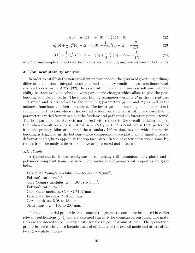
Considering the first strut, where b = 5.08 mm and L = 100 mm, overall buckling iscritical once the secondary bifurcation is located the strut subsequently destabilizes, rapidlylosing its load carrying capacity as seen in Figure 5(a). It can be seen that by comparing
E=L0 0.02 0.04 0.06 0.08 0.1 0.12
p
0
0.2
0.4
0.6
0.8
1model
TBmodel
1998
(a)
qt
0 0.01 0.02 0.03 0.04 0.05 0.06 0.07
q s
0
0.05
0.1
0.15
0.2
0.25
0.3
0.35
modelTB
model1998
Secondary bifurcation point
Primary bifurcation point
(b)
E=L0 0.02 0.04 0.06 0.08 0.1 0.12
p
0
0.2
0.4
0.6
0.8
1model
TBmodel
1998
(c)
qt
0 0.005 0.01 0.015 0.02 0.025 0.03
q s
0
0.05
0.1
0.15
0.2
0.25
0.3
modelTB
model1998
Primary bifurcation point
Secondary bifurcation point
(d)
Figure 5: Left: Plotting p versus normalized end shortening (E/L). Right: Plotting amplitude of tilt qtversus amplitude of sway qs for struts of length L = 100 mm and different core depths. b= 5.08 mm for(a) and (b) and b = 10.16 mm for (c) and (d).
the two models, no significant differences can be observed in the post-buckling unloadingresponse beyond the secondary bifurcation. Some very minor differences can be seen inFigure 5(c), which depicts the response of a sandwich strut of core depth b = 10.16 mm andlength L = 100 mm. In both instances, the new model (thereafter termed ‘modelTB’) hasa marginally steeper post-buckling but, nonetheless, following the same unloading trend.A slightly more measureable difference beyond the critical (primary) bifurcation is visible
11
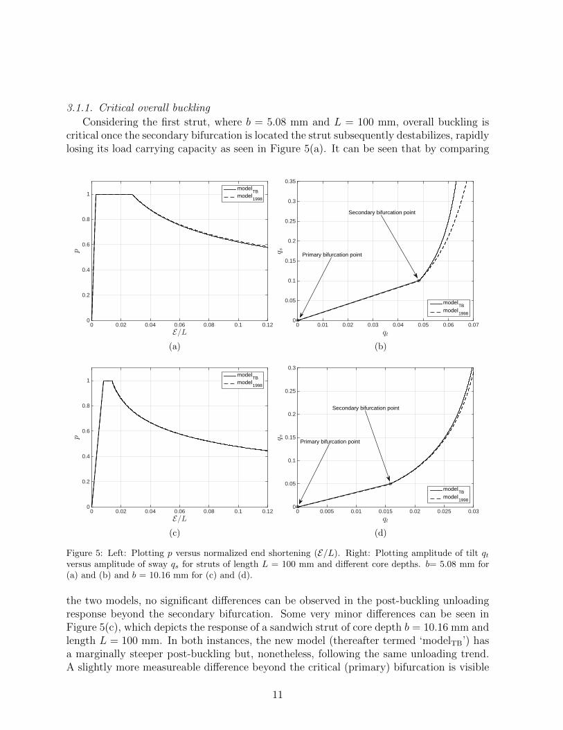
when comparing the tilt and sway components of the overall mode directly, as shown inFigures 5(b) and (d). These differences, however small, are attributed to the formation oflocal deformations occurring at the top (less compressed) face plate, which were inhibitedwithin the 1998 model. As seen in Figure 6, which exhibits the evolution of interactivemodes wb, wt, ub, ut with P unloading, as soon as the interactive localized buckle appearswithin the more compressed face plate, a quasi-periodic buckle pattern appears in theother. The top face plate deformation begins for all configurations as a shallow negativedisplacement, flattening the top face plate at mid-span and down the post-buckling path,two more half sine waves begin appearing at the two ends. These diagrams show the na-
(a) (b)
(c) (d)
Figure 6: (a) Local mode evolution of face plates unloading for a strut of length L = 175 mm and coredepth b = 5.08 mm. (a) wt (b) wb, (c) ut and (d) ub.
ture, as well as the comparative magnitude, of the interactive modes. The first observationis that the modes corresponding to the top face plate are smaller in magnitude comparedto the ones corresponding to the bottom face plate. This can be attributed to the fact that
12
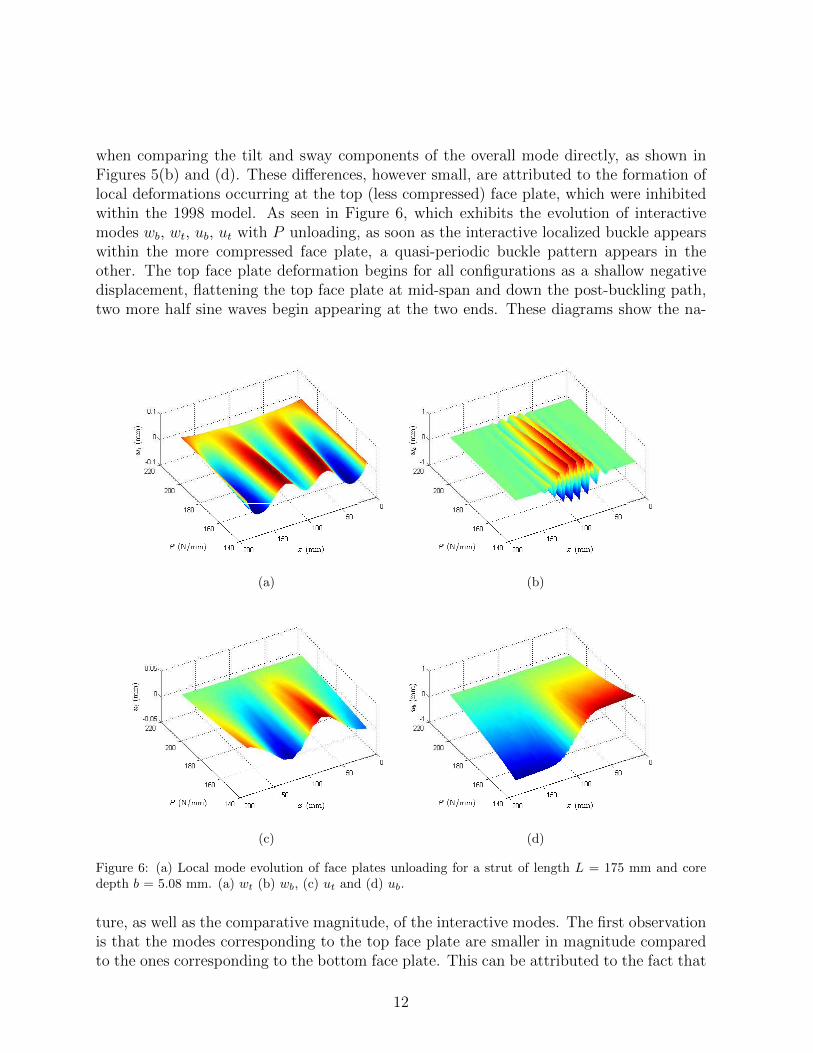
the localized interactive buckling displacement occurring within the bottom face plate isa signature of a destabilizing phenomenon and hence grows faster during unloading. Thedisplacement wt, however small, contributes to the flattening of the top face plate dur-ing post-buckling (Figure 7). Parametric studies, while keeping the core depth constant,
0 10 20 30 40 50 60 70 80 90 100
0
10
20
30
40
x (mm)
y(m
m)
ModelTB
Model1998
(a)
45 50 55 60 65 70
20
22
24
26
28
x (mm)
y(m
m)
ModelTB
Model1998
(b)
Figure 7: (a) The overall deformations on a b=5.08 mm and L =100 mm strut at p = 0.7. (b) A closelook at midspan deformations. While the bottom face plate deformations are easily observed, the top faceplate local deformations are not as clear but contribute to the flattening of the top face plate.
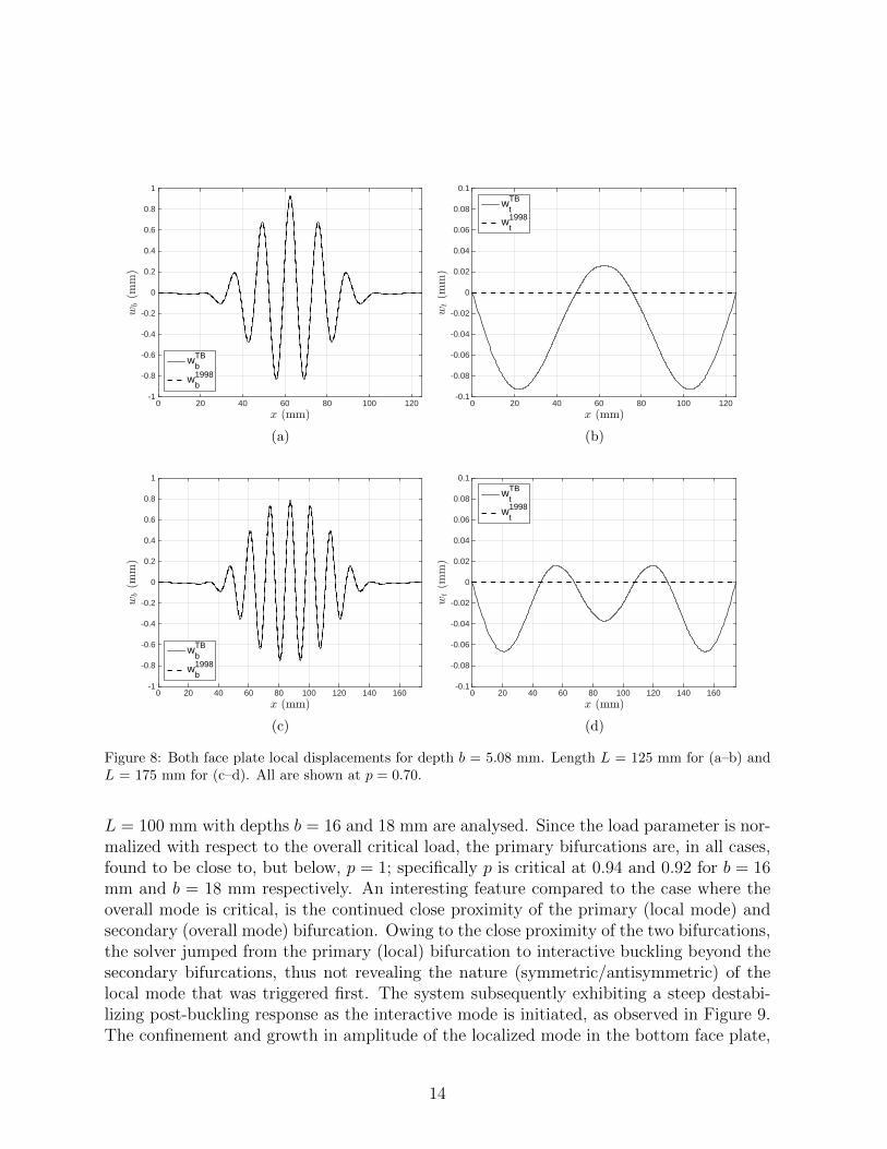
demonstrate that with increasing length the periodicity in the deformations of the top faceplate is maintained, albeit with an increasing number of half sine waves and diminishinggrowth, as shown in Figure 8. This is expected since with increasing length, more half sinewaves would be generated in the most energetically favourable buckle pattern. The ampli-tude of the less compressed face plate local deformations does not change with increasinglength at different p levels. These local deformations are independent of the localized modethat manifests in the more compressed face plate, as shown in Equations (2)-(3). Moreoverthey have a different wavelength and their amplitude is uniform, unlike the localized modewhich is concentrated at midspan. A further parametric study, performed by investigatingthe amplitude and nature of deformations for different sandwich depths at constant p levels,exhibited an insensitivity to the amplitude of the less compressed face plate deformations;this maintained a constant local displacement amplitude to depth ratio. Conversely, theinteractive mode in the more compressed face plate becomes more localized with increasingdepth, for the different depths (5.08 to 14 mm). As the load rapidly decreases during post-buckling, local plate buckling at the top does not grow and its effect is quickly diminisheddue to the tensile stresses from bending introduced by the overall buckling component.
3.1.2. Critical local buckling
An important feature of the model presented currently is that it enables the investi-gation of interactive localized buckling when local buckling occurs first. The second caseconsiders deeper struts where local buckling becomes critical. Example struts of length
13
x (mm)0 20 40 60 80 100 120
wb(m
m)
-1
-0.8
-0.6
-0.4
-0.2
0
0.2
0.4
0.6
0.8
1
wbTB
wb1998
(a)
x (mm)0 20 40 60 80 100 120
wt(m
m)
-0.1
-0.08
-0.06
-0.04
-0.02
0
0.02
0.04
0.06
0.08
0.1
wtTB
wt1998
(b)
x (mm)0 20 40 60 80 100 120 140 160
wb(m
m)
-1
-0.8
-0.6
-0.4
-0.2
0
0.2
0.4
0.6
0.8
1
wbTB
wb1998
(c)
x (mm)0 20 40 60 80 100 120 140 160
wt(m
m)
-0.1
-0.08
-0.06
-0.04
-0.02
0
0.02
0.04
0.06
0.08
0.1
wtTB
wt1998
(d)
Figure 8: Both face plate local displacements for depth b = 5.08 mm. Length L = 125 mm for (a–b) andL = 175 mm for (c–d). All are shown at p = 0.70.
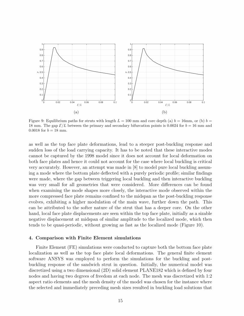
L = 100 mm with depths b = 16 and 18 mm are analysed. Since the load parameter is nor-malized with respect to the overall critical load, the primary bifurcations are, in all cases,found to be close to, but below, p = 1; specifically p is critical at 0.94 and 0.92 for b = 16mm and b = 18 mm respectively. An interesting feature compared to the case where theoverall mode is critical, is the continued close proximity of the primary (local mode) andsecondary (overall mode) bifurcation. Owing to the close proximity of the two bifurcations,the solver jumped from the primary (local) bifurcation to interactive buckling beyond thesecondary bifurcations, thus not revealing the nature (symmetric/antisymmetric) of thelocal mode that was triggered first. The system subsequently exhibiting a steep destabi-lizing post-buckling response as the interactive mode is initiated, as observed in Figure 9.The confinement and growth in amplitude of the localized mode in the bottom face plate,
14
E=L0 0.02 0.04 0.06 0.08 0.1
p
0
0.1
0.2
0.3
0.4
0.5
0.6
0.7
0.8
0.9
1
(a)
E=L0 0.02 0.04 0.06 0.08 0.1
p
0
0.1
0.2
0.3
0.4
0.5
0.6
0.7
0.8
0.9
1
(b)
Figure 9: Equilibrium paths for struts with length L = 100 mm and core depth (a) b = 16mm, or (b) b =18 mm. The gap E/L between the primary and secondary bifurcation points is 0.0024 for b = 16 mm and0.0018 for b = 18 mm.
as well as the top face plate deformations, lead to a steeper post-buckling response andsudden loss of the load carrying capacity. It has to be noted that these interactive modescannot be captured by the 1998 model since it does not account for local deformation onboth face plates and hence it could not account for the case where local buckling is criticalvery accurately. However, an attempt was made in [8] to model pure local buckling assum-ing a mode where the bottom plate deflected with a purely periodic profile; similar findingswere made, where the gap between triggering local buckling and then interactive bucklingwas very small for all geometries that were considered. More differences can be foundwhen examining the mode shapes more closely, the interactive mode observed within themore compressed face plate remains confined to the midspan as the post-buckling responseevolves, exhibiting a higher modulation of the main wave, further down the path. Thiscan be attributed to the softer nature of the strut that has a deeper core. On the otherhand, local face plate displacements are seen within the top face plate, initially as a sizablenegative displacement at midspan of similar amplitude to the localized mode, which thentends to be quasi-periodic, without growing as fast as the localized mode (Figure 10).
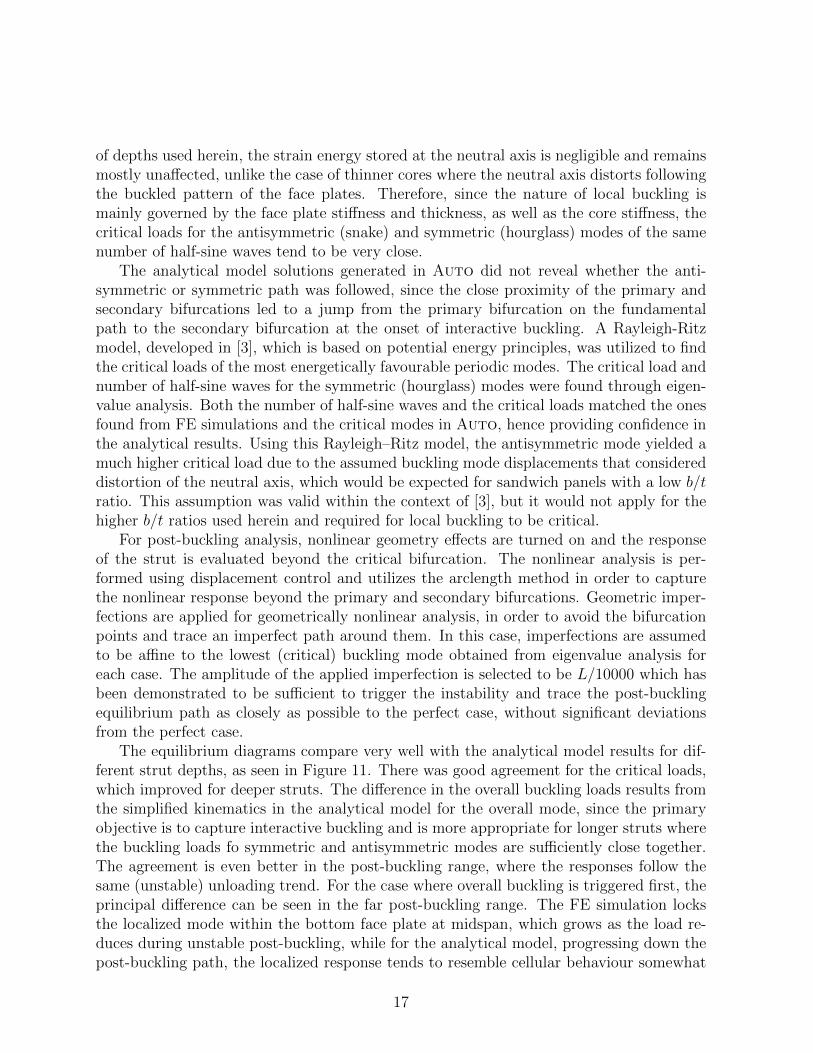
4. Comparison with Finite Element simulations
Finite Element (FE) simulations were conducted to capture both the bottom face platelocalization as well as the top face plate local deformations. The general finite elementsoftware ANSYS was employed to perform the simulations for the buckling and post-buckling response of the sandwich strut in question. Initially, the numerical model wasdiscretized using a two dimensional (2D) solid element PLANE182 which is defined by fournodes and having two degrees of freedom at each node. The mesh was discretized with 1:2aspect ratio elements and the mesh density of the model was chosen for the instance wherethe selected and immediately preceding mesh sizes resulted in buckling load solutions that
15
x (mm)0 10 20 30 40 50 60 70 80 90 100
y(m
m)
-10
-5
0
5
10
15
20
25
(a)
x (mm)0 20 40 60 80 100
wt;
wb(m
m)
-3
-2
-1
0
1
2
3
4
5
wb
wt
(b)
Figure 10: (a) Interactive mode deformation profile for a strut of length L = 100 mm and core depthb = 16 mm. (b) Local modes within the top and bottom face plate at E/L = 10% within the interactivepost-buckling range.
were within 0.5% of each other.In order to match the analytical model as closely as possible, the core depth b′ is
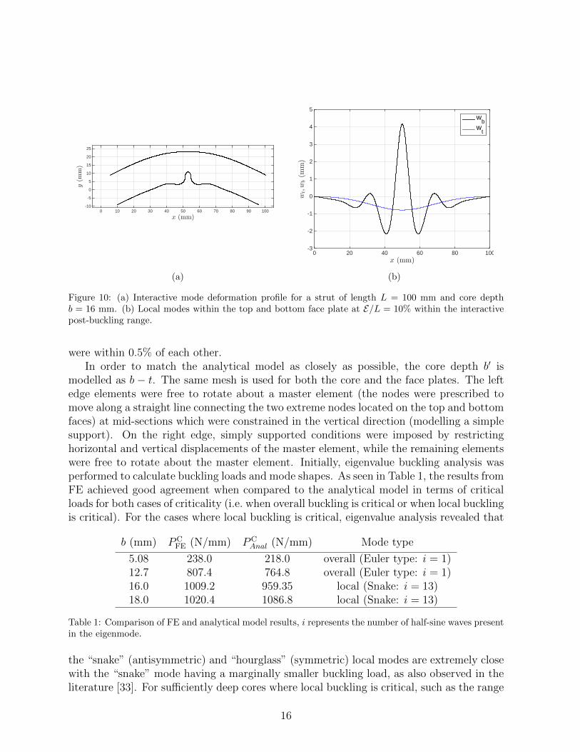
modelled as b − t. The same mesh is used for both the core and the face plates. The leftedge elements were free to rotate about a master element (the nodes were prescribed tomove along a straight line connecting the two extreme nodes located on the top and bottomfaces) at mid-sections which were constrained in the vertical direction (modelling a simplesupport). On the right edge, simply supported conditions were imposed by restrictinghorizontal and vertical displacements of the master element, while the remaining elementswere free to rotate about the master element. Initially, eigenvalue buckling analysis wasperformed to calculate buckling loads and mode shapes. As seen in Table 1, the results fromFE achieved good agreement when compared to the analytical model in terms of criticalloads for both cases of criticality (i.e. when overall buckling is critical or when local bucklingis critical). For the cases where local buckling is critical, eigenvalue analysis revealed that
b (mm) PCFE (N/mm) PC
Anal (N/mm) Mode type
5.08 238.0 218.0 overall (Euler type: i = 1)12.7 807.4 764.8 overall (Euler type: i = 1)16.0 1009.2 959.35 local (Snake: i = 13)18.0 1020.4 1086.8 local (Snake: i = 13)
Table 1: Comparison of FE and analytical model results, i represents the number of half-sine waves presentin the eigenmode.
the “snake” (antisymmetric) and “hourglass” (symmetric) local modes are extremely closewith the “snake” mode having a marginally smaller buckling load, as also observed in theliterature [33]. For sufficiently deep cores where local buckling is critical, such as the range
16
of depths used herein, the strain energy stored at the neutral axis is negligible and remainsmostly unaffected, unlike the case of thinner cores where the neutral axis distorts followingthe buckled pattern of the face plates. Therefore, since the nature of local buckling ismainly governed by the face plate stiffness and thickness, as well as the core stiffness, thecritical loads for the antisymmetric (snake) and symmetric (hourglass) modes of the samenumber of half-sine waves tend to be very close.
The analytical model solutions generated in Auto did not reveal whether the anti-symmetric or symmetric path was followed, since the close proximity of the primary andsecondary bifurcations led to a jump from the primary bifurcation on the fundamentalpath to the secondary bifurcation at the onset of interactive buckling. A Rayleigh-Ritzmodel, developed in [3], which is based on potential energy principles, was utilized to findthe critical loads of the most energetically favourable periodic modes. The critical load andnumber of half-sine waves for the symmetric (hourglass) modes were found through eigen-value analysis. Both the number of half-sine waves and the critical loads matched the onesfound from FE simulations and the critical modes in Auto, hence providing confidence inthe analytical results. Using this Rayleigh–Ritz model, the antisymmetric mode yielded amuch higher critical load due to the assumed buckling mode displacements that considereddistortion of the neutral axis, which would be expected for sandwich panels with a low b/tratio. This assumption was valid within the context of [3], but it would not apply for thehigher b/t ratios used herein and required for local buckling to be critical.
For post-buckling analysis, nonlinear geometry effects are turned on and the responseof the strut is evaluated beyond the critical bifurcation. The nonlinear analysis is per-formed using displacement control and utilizes the arclength method in order to capturethe nonlinear response beyond the primary and secondary bifurcations. Geometric imper-fections are applied for geometrically nonlinear analysis, in order to avoid the bifurcationpoints and trace an imperfect path around them. In this case, imperfections are assumedto be affine to the lowest (critical) buckling mode obtained from eigenvalue analysis foreach case. The amplitude of the applied imperfection is selected to be L/10000 which hasbeen demonstrated to be sufficient to trigger the instability and trace the post-bucklingequilibrium path as closely as possible to the perfect case, without significant deviationsfrom the perfect case.
The equilibrium diagrams compare very well with the analytical model results for dif-ferent strut depths, as seen in Figure 11. There was good agreement for the critical loads,which improved for deeper struts. The difference in the overall buckling loads results fromthe simplified kinematics in the analytical model for the overall mode, since the primaryobjective is to capture interactive buckling and is more appropriate for longer struts wherethe buckling loads fo symmetric and antisymmetric modes are sufficiently close together.The agreement is even better in the post-buckling range, where the responses follow thesame (unstable) unloading trend. For the case where overall buckling is triggered first, theprincipal difference can be seen in the far post-buckling range. The FE simulation locksthe localized mode within the bottom face plate at midspan, which grows as the load re-duces during unstable post-buckling, while for the analytical model, progressing down thepost-buckling path, the localized response tends to resemble cellular behaviour somewhat
17
E=L0 0.02 0.04 0.06 0.08 0.1
p
0
0.2
0.4
0.6
0.8
1model
TBFE
(a)
E=L0 0.02 0.04 0.06 0.08 0.1
p
0
0.2
0.4
0.6
0.8
1model
TBFE
(b)
E=L0 0.02 0.04 0.06 0.08 0.1
p
0
0.1
0.2
0.3
0.4
0.5
0.6
0.7
0.8
0.9
1model
TBFE
(c)
E=L0 0.02 0.04 0.06 0.08 0.1
p
0
0.1
0.2
0.3
0.4
0.5
0.6
0.7
0.8
0.9
1model
TBFE
(d)
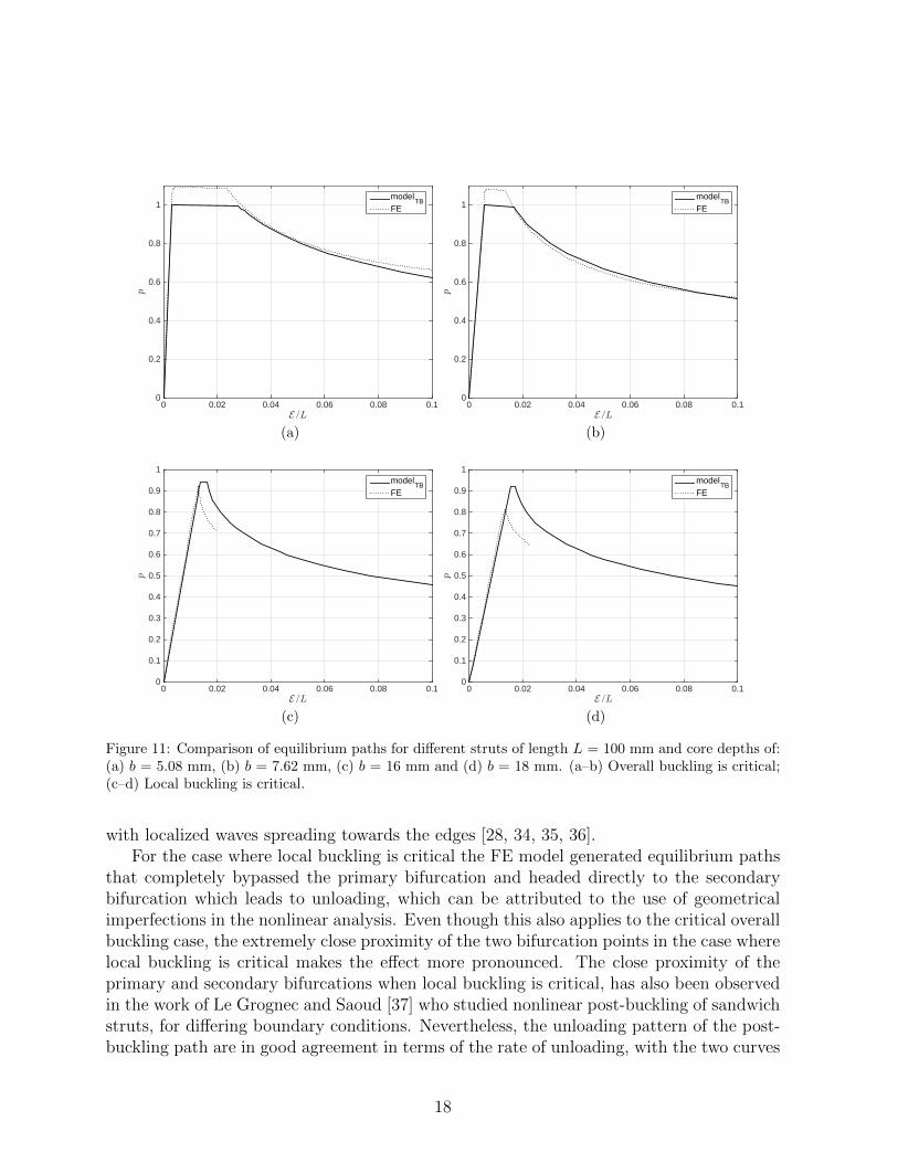
Figure 11: Comparison of equilibrium paths for different struts of length L = 100 mm and core depths of:(a) b = 5.08 mm, (b) b = 7.62 mm, (c) b = 16 mm and (d) b = 18 mm. (a–b) Overall buckling is critical;(c–d) Local buckling is critical.
with localized waves spreading towards the edges [28, 34, 35, 36].For the case where local buckling is critical the FE model generated equilibrium paths
that completely bypassed the primary bifurcation and headed directly to the secondarybifurcation which leads to unloading, which can be attributed to the use of geometricalimperfections in the nonlinear analysis. Even though this also applies to the critical overallbuckling case, the extremely close proximity of the two bifurcation points in the case wherelocal buckling is critical makes the effect more pronounced. The close proximity of theprimary and secondary bifurcations when local buckling is critical, has also been observedin the work of Le Grognec and Saoud [37] who studied nonlinear post-buckling of sandwichstruts, for differing boundary conditions. Nevertheless, the unloading pattern of the post-buckling path are in good agreement in terms of the rate of unloading, with the two curves
18
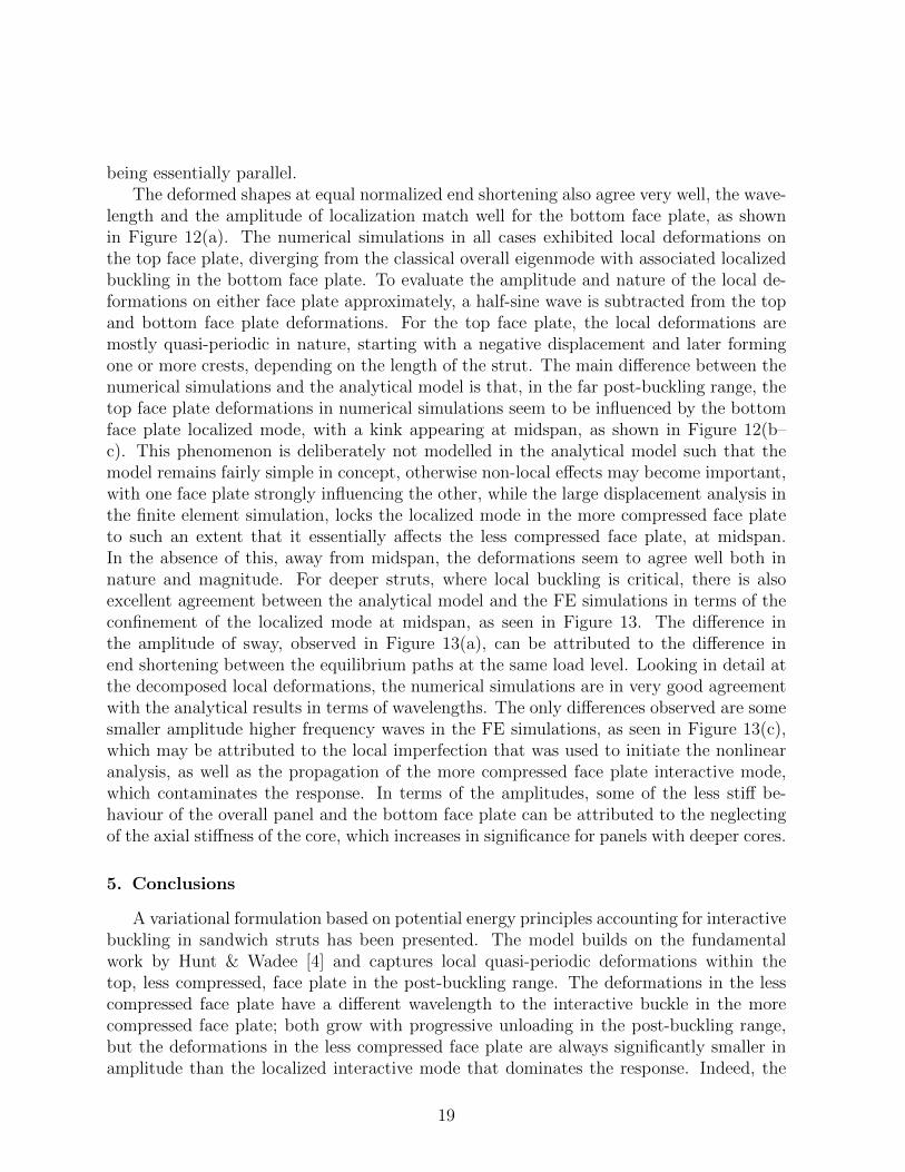
being essentially parallel.The deformed shapes at equal normalized end shortening also agree very well, the wave-
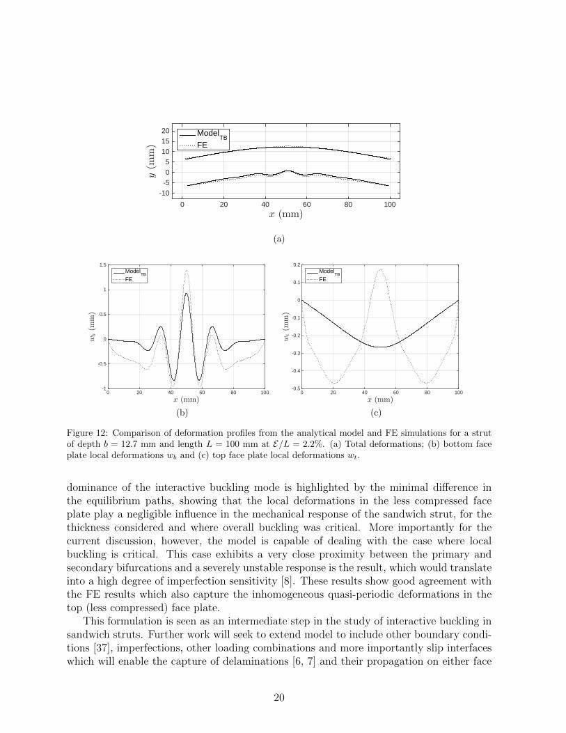
length and the amplitude of localization match well for the bottom face plate, as shownin Figure 12(a). The numerical simulations in all cases exhibited local deformations onthe top face plate, diverging from the classical overall eigenmode with associated localizedbuckling in the bottom face plate. To evaluate the amplitude and nature of the local de-formations on either face plate approximately, a half-sine wave is subtracted from the topand bottom face plate deformations. For the top face plate, the local deformations aremostly quasi-periodic in nature, starting with a negative displacement and later formingone or more crests, depending on the length of the strut. The main difference between thenumerical simulations and the analytical model is that, in the far post-buckling range, thetop face plate deformations in numerical simulations seem to be influenced by the bottomface plate localized mode, with a kink appearing at midspan, as shown in Figure 12(b–c). This phenomenon is deliberately not modelled in the analytical model such that themodel remains fairly simple in concept, otherwise non-local effects may become important,with one face plate strongly influencing the other, while the large displacement analysis inthe finite element simulation, locks the localized mode in the more compressed face plateto such an extent that it essentially affects the less compressed face plate, at midspan.In the absence of this, away from midspan, the deformations seem to agree well both innature and magnitude. For deeper struts, where local buckling is critical, there is alsoexcellent agreement between the analytical model and the FE simulations in terms of theconfinement of the localized mode at midspan, as seen in Figure 13. The difference inthe amplitude of sway, observed in Figure 13(a), can be attributed to the difference inend shortening between the equilibrium paths at the same load level. Looking in detail atthe decomposed local deformations, the numerical simulations are in very good agreementwith the analytical results in terms of wavelengths. The only differences observed are somesmaller amplitude higher frequency waves in the FE simulations, as seen in Figure 13(c),which may be attributed to the local imperfection that was used to initiate the nonlinearanalysis, as well as the propagation of the more compressed face plate interactive mode,which contaminates the response. In terms of the amplitudes, some of the less stiff be-haviour of the overall panel and the bottom face plate can be attributed to the neglectingof the axial stiffness of the core, which increases in significance for panels with deeper cores.
5. Conclusions
A variational formulation based on potential energy principles accounting for interactivebuckling in sandwich struts has been presented. The model builds on the fundamentalwork by Hunt & Wadee [4] and captures local quasi-periodic deformations within thetop, less compressed, face plate in the post-buckling range. The deformations in the lesscompressed face plate have a different wavelength to the interactive buckle in the morecompressed face plate; both grow with progressive unloading in the post-buckling range,but the deformations in the less compressed face plate are always significantly smaller inamplitude than the localized interactive mode that dominates the response. Indeed, the
19
x (mm)0 20 40 60 80 100
y(m
m)
-10
-5
0
5
10
15
20 ModelTB
FE
(a)
x (mm)0 20 40 60 80 100
wb(m
m)
-1
-0.5
0
0.5
1
1.5Model
TBFE
(b)
x (mm)0 20 40 60 80 100
wt(m
m)
-0.5
-0.4
-0.3
-0.2
-0.1
0
0.1
0.2Model
TBFE
(c)
Figure 12: Comparison of deformation profiles from the analytical model and FE simulations for a strutof depth b = 12.7 mm and length L = 100 mm at E/L = 2.2%. (a) Total deformations; (b) bottom faceplate local deformations wb and (c) top face plate local deformations wt.
dominance of the interactive buckling mode is highlighted by the minimal difference inthe equilibrium paths, showing that the local deformations in the less compressed faceplate play a negligible influence in the mechanical response of the sandwich strut, for thethickness considered and where overall buckling was critical. More importantly for thecurrent discussion, however, the model is capable of dealing with the case where localbuckling is critical. This case exhibits a very close proximity between the primary andsecondary bifurcations and a severely unstable response is the result, which would translateinto a high degree of imperfection sensitivity [8]. These results show good agreement withthe FE results which also capture the inhomogeneous quasi-periodic deformations in thetop (less compressed) face plate.
This formulation is seen as an intermediate step in the study of interactive buckling insandwich struts. Further work will seek to extend model to include other boundary condi-tions [37], imperfections, other loading combinations and more importantly slip interfaceswhich will enable the capture of delaminations [6, 7] and their propagation on either face
20
x (mm)0 20 40 60 80 100
y(m
m)
-10
0
10
20 ModelTB
FE
(a)
x (mm)0 20 40 60 80 100
wb(m
m)
-1
-0.8
-0.6
-0.4
-0.2
0
0.2
0.4
0.6
0.8
1Model
TBFE
(b)
x (mm)0 20 40 60 80 100
wt(m
m)
-0.4
-0.35
-0.3
-0.25
-0.2
-0.15
-0.1
-0.05
0
ModelTB
FE
(c)
Figure 13: Comparison of deformation profiles from the analytical model and FE simulations for a strut ofdepth b = 16 mm and length L = 100 mm at p = 0.80. (a) Total deformations; (b) bottom face plate localdeformations wb and (c) top face plate local deformations wt. Note that the FE result in (a) is possiblyaffected by the chosen imperfection used to trigger buckling in the nonlinear analysis.
plate. Finally the authors are planning the development of experimental tests to captureinteractive buckling and inhomogeneous deformations in the panels using Digital ImageCorrelation (DIC) techniques through photogrammetric methods [38].
Acknowledgment
The authors would like to acknowledge the financial support of the Cyprus Universityof Technology New Academic Startup Fund as part of the project “Functionally OptimizedStructures”.
21
References
[1] Zenkert D. An introduction to sandwich construction. London: Engineering MaterialsAdvisory Services Ltd; 1995.
[2] Goodier JN. Cylindrical buckling of sandwich plates. Trans ASME J Appl Mech1946;13(4):A253–60.
[3] Hunt GW, Da Silva LS, Manzocchi GME. Interactive buckling in sandwich structures.Proc R Soc 1988;A 417:155–77.
[4] Hunt GW, Wadee MA. Localization and mode interaction in sandwich structures.Proc R Soc A 1998;454:1197–216.
[5] Wadee MA, Yiatros S, Theofanous M. Comparative studies of localized bucklingin sandwich struts with different core bending models. Int J Non-Linear Mech2010;45:111–20.
[6] Wadee MA, Blackmore A. Delamination from localized instabilities in compressionsandwich panels. J Mech Phys Solids 2001;49(6):1281–99.
[7] Østergaard RC. Buckling driven debonding in sandwich columns. Int J Solids Struct2008;45:1264–82.
[8] Wadee MA. Effects of periodic and localized imperfections on struts on nonlinearfoundations and compression sandwich panels. Int J Solids Struct 2000;37(8):1191–209.
[9] Allen HG. Analysis and design of structural sandwich panels. Oxford: Pergamon;1969.
[10] Plantema FJ. Sandwich construction: The bending and buckling of sandwich beams,plates and shells. New York: Wiley; 1966.
[11] Fazio P, Hussein R, Ha KH. Sandwich beam-columns with interlayer slips. ASCE JEng Mech Div 1982;108(2):354–66.
[12] Drysdale RG, Betancourt-Angel F, Haddad GB. Thick skin sandwich beam columnswith weak cores. ASCE J Struct Div 1979;105(12):2601–19.
[13] Sokolinsky V, Frostig Y. Branching behavior in the nonlinear response of sandwichpanels with a transversely flexible core. Int J Solids Struct 2000;37:5745–72.
[14] Frostig Y, Thomsen OT. Localized effects in the nonlinear behavior of sandwich panelswith a transversely flexible core. J Sandw Struct Mater 2006;7:53–75.
[15] Hadi BK. Wrinkling of sandwich column: comparison between finite element analysisand analytical solutions. Compos Struct 2001;53(4):477–82.
22
[16] Leotoing L, Drapier S, Vautrin A. First applications of a novel unified model for globaland local buckling of sandwich columns. Eur J Mech – A/Solids 2002;21(4):683–701.
[17] Hu H, Belouettar S, Potier-Ferry M, Makradi A. A novel finite element for global andlocal buckling analysis of sandwich beams. Compos Struct 2009;90:270–8.
[18] Hu H, Belouettar S, Potier-Ferry M, Makradi A, Koutsawa Y. Assessment ofvarious kinematic models for instability analysis of sandwich beams. Eng Struct2011;33(2):572–9.
[19] Douville MA, Le Grognec P. Exact analytical solutions for the local and global buck-ling of sandwich beam-columns under various loadings. Int J Solids Struct 2013;50(16-17):2597–609.
[20] Yu K, Hu H, Chen S, Belouettar S, Potier-Ferry M. Multi-scale techniques to analyzeinstabilities in sandwich structures. Compos Struct 2013;96:751–62.
[21] Leotoing L, Drapier S, Vautrin A. Nonlinear interaction of geometrical and materialproperties in sandwich beam instabilities. Int J Solids Struct 2002;39(13–14):3717–39.
[22] Wadee MA, Hunt GW. Interactively induced localized buckling in sandwich structureswith core orthotropy. Trans ASME J Appl Mech 1998;65(2):523–8.
[23] Yiatros S, Wadee MA. Interactive buckling in sandwich beam-columns. IMA J ApplMath 2011;76:146–88.
[24] Yiatros S, Wadee MA, Vollmecke C. Modeling of interactive buckling in sandwichstruts with functionally graded cores. J Eng Mech ASCE 2013;139:952–60.
[25] Jasion P, Magnucka-Blandzi E, Szyc W, Magnucki K. Global and local buckling ofsandwich circular and beam-rectangular plates with metal foam core. Thin-WalledStruct 2012;61:154–61.
[26] Szyniszewski S, Smith BH, Hajjar JF, Arwade SR, Schafer BW. Local bucklingstrength of steel foam sandwich panels. Thin-Walled Struct 2012;59:11–9.
[27] Laine C, Le Grognec P, Comas Cardona S, Binetruy C. Analytical, numerical and ex-perimental study of the bifurcation and collapse behavior of a 3D reinforced sandwichstructure under through-thickness compression. Int J Mech Sci 2013;67:42–52.
[28] Wadee MA, Bai L. Cellular buckling in I-section struts. Thin-Walled Struct2014;81:89–100.
[29] Wadee MA. Experimental evaluation of interactive buckle localization in compressionsandwich panels. J Sandw Struct Mater 1999;1(3):230–54.
[30] ANSYS Academic Research LS-DYNA. ANSYS Inc.; 2015.
23
[31] Fox C. An introduction to the calculus of variations. New York: Dover; 1987.
[32] Doedel EJ. AUTO07-p: Continuation and bifurcation software for ordinary differen-tial equations. Tech. Rep.; Department of Computer Science, Concordia University,Montreal, Canada; 2007.
[33] Williams D, Leggett DMA, Hopkins HG. Flat sandwich panels under compressive endloads. aeronautical research committee reports and memoranda no. 1987. Tech. Rep.;Ministry of Aircraft Production, London.; 1941.
[34] Hunt GW, Peletier MA, Champneys AR, Woods PD, Wadee MA, Budd CJ, et al.Cellular buckling in long structures. Nonlin Dyn 2000;21(1):3–29.
[35] Wadee MA, Gardner L. Cellular buckling from mode interaction in I-beams underuniform bending. Proc R Soc A 2012;468:245–68.
[36] Wadee MA, Farsi M. Cellular buckling in stiffened plates. Proc R Soc A2014;470:20140094.
[37] Le Grognec P, Saoud KS. Elastoplastic buckling and post-buckling analysis of sand-wich columns. Int J Non-Linear Mech 2015;72:67–79.
[38] Sinur F, Zizza A, Kuhlmann U, Beg D. Buckling interaction of slender plates—Experimental and numerical investigations . Thin-Walled Struct 2012;61:121–31.
24


![Buckling Analysis of Aluminum Foam Sandwich Plates and ... · [35] S. Yusuff. Face wrinkling and core strength in sandwich construction. Journal of the Royal Aeronautical Society,](https://img.pdfslide.us/doc/110x75/5bcb8c4509d3f2761f8c3d4c/buckling-analysis-of-aluminum-foam-sandwich-plates-and-35-s-yusuff-face.jpg)