Embed Size (px)
Citation preview
THINKING INSIDE THE BOX – DEVELOPMENT OF A MONOHULL FAST LANDING
CRAFT
R Sime and E Dudson, BMT Nigel Gee Ltd, UK
S Amaratunga, BMT Defence Services Ltd, UK
SUMMARY
The UK Ministry of Defence (MoD) is planning to replace the existing Mk10 landing craft with a fleet of new Fast
Landing Craft (FLC) capable of over-the-horizon surface assault. Challenging dimensional constraints governed by the
requirement to operate from within existing UK amphibious support vessels, coupled with the high speed and heavy
payload requirements necessitates an innovative solution. Furthermore, the craft must exhibit excellent beach stability to
ensure that landing force capability can be off-loaded safely.
Following a detailed study of potential hullform solutions covering a range of basic and advanced forms, BMT has
identified a novel monohull form as a potential candidate for future FLC technology. An extensive research and
development (R&D) program has been conducted to assess the performance of three monohull variants, each exhibiting
varying degrees of beach stability. The results have confirmed that a novel monohull form with inherent beach stability
can meet the demanding performance requirements with reasonable levels of installed power.
This paper describes the design development and testing of the monohull FLC, and demonstrates how relatively simple
monohull technology can be optimised to offer a novel solution by ‘thinking inside the box’.
1. INTRODUCTION
It is a fundamental requirement that the future FLC must
be designed to operate within the same footprint as
existing Mk10 landing craft in order that the amphibious
assault force can continue to operate from existing
Landing Platform Dock (LPD) ships (Figure 1) such as
HMS Albion and HMS Bulwark.
Figure 1: FLC integration with LPD
The requirement to operate from within an existing LPD
provides a challenging set of dimensional constraints
with regard to length, beam, draught and air draught.
Furthermore, with the high speed, high payload and
demanding seakeeping requirements, and the need to
exhibit excellent beach stability, the design requirements
are also very challenging.
However, a challenging set of design requirements does
not necessarily require a complex design solution.
Following a review of a wide range of hullform types,
BMT has identified that a novel monohull, properly
designed, can meet the complex design and operational
requirements presented in Figure 2.
Fixed constraints on maximum dimensions
- Maximum Length 30.0 metres
- Maxmium Beam 7.7 metres
- Maximum Draught (Loaded) 1.5 metres
- Maximum Air Draught 5.5 metres
High payload and high speed requirements relative to
displacement
Payload – 1 x Main Battle Tank (MBT)
- Total deadweight ~ 90 tonnes
- Operating speed > 21 knots
Payload – 4 x All Terrain Vehicles (ATVP)
- Total deadweight ~ 65 tonnes
- Operating speed > 27 knots
Figure 2: Table of design requirements
The philosophy of ‘thinking inside the box’ therefore
refers not only to the literal implications associated with
the box constraints of the LPD, but also the idea that a
relatively simple solution can be developed to address
what is undoubtedly a complex requirement.
The paper starts by describing the work that BMT
initially undertook in developing a range of monohull
FLC hullforms as part of an internally funded R&D
study. The paper goes on to describe the further design
development and model testing of the proposed solution
which was carried out as part of a Design Solutions
Study (DSS) for MoD.
2. KEY CONSIDERATIONS
2.1 HYDRODYNAMIC REQUIREMENTS
The current Mk10 landing craft demonstrate
conventional ‘pram’ style monohull forms with a very
low degree of deadrise, and with additional beaching
strakes fitted to the hull bottom to offer adequate beach
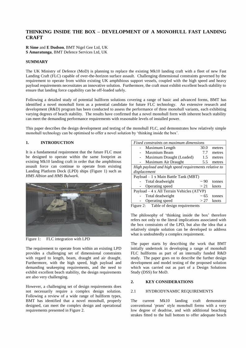
stability. The Mk10 hullform demonstrates a high degree
of ‘buttock flow’ rather than the more preferable
‘waterline flow’ for higher speed vessels. As shown in
Figure 3, the bow ramp of the existing Mk10 is hinged
very close to the waterline in order to minimise the
length of the ramp and reduce air draught. These
features severely limit the speed capabilities of the
Mk10, resulting in a maximum loaded speed of
approximately 9 knots. Furthermore, with a wide, flat
bow ramp the existing vessels are often subjected to
heavy slamming loads in a seaway.
Figure 3: Conventional landing craft ramp design
At 27 knots, the FLC speed requirement is three times
the speed capability of the current Mk10 landing craft.
Figure 4 highlights some important hydrodynamic
particulars including details of waterline length,
displacement, primary hull coefficients and operating
Froude number. It can be seen that the operating Froude
number is very high relative to the displacement, and in
the early stages of the FLC design development it was
concluded that to achieve high speed operation, the
vessel had to be designed as a lightweight (aluminium or
composite) monohull to increase length-displacement
ratio and minimise block coefficient as far as possible.
Length and displacement
- Waterline Length 27.2 metres
- Displacement 210 tonnes
(MBT Load)
- Length-Displacement Ratio 4.6
Hull coefficients
- Block coefficient ~0.7
- Prismatic coefficient ~0.8
Speed regime
- Operating Froude number 0.85
(27 knots)
Figure 4: Principal hydrodynamic requirements
2.2 BOW RAMP INVESTIGATIONS
Another fundamental consideration of the hydrodynamic
design development was the arrangement of the bow
ramp. The requirement to unload an MBT over the bow
of the vessel demands a very wide, flat ramp which is
likely to suffer from severe slamming in head seas and
limit the potential speed of the vessel. It is clear that the
standard type of ramp as installed on the Mk10 would be
impractical for high speed operations in a seaway.
Consequently, bow ramp investigations were carried out
to identify a number of solutions which would improve
the seakeeping capabilities of a monohull FLC.
A range of existing ramp technologies were explored to
identify those that could potentially be applied to FLC
applications. Existing technologies such as bow visors,
clam shell doors, bow ramp fairings and folding ramps
were assessed with regard to a number of design
considerations including:
Calm water resistance
Seakeeping performance
Air draught limitations
Spatial impact
Beach stability
Bow visors, clam shell doors and bow ramp fairings were
all considered to impact on the mission capability of the
vessel, or require complex engineering solutions. A bi-
fold ramp with its hinge point located far above the
waterline was identified as the optimum solution to
improve seakeeping at high speeds, whilst meeting all
operational and dimensional constraints. Furthermore,
folding ramp technology is already well proven in
commercial applications, including landing craft.
3. INITIAL HULLFORM DEVELOPMENT
3.1 BACKGROUND
The initial monohull FLC hullform development formed
part of an internal R&D study funded by BMT. The
main focus of the R&D study was to develop a novel
monohull within the fixed constraints presented in Figure
2, capable of speeds in excess of 27 knots, whilst
maintaining reasonable seakeeping and beaching
capabilities. The R&D was divided into two stages:
Stage 1 – hydrodynamic development of suitable
hullform options,
Stage 2 – model testing to confirm calm water
capabilities of the various options.
3.2 R&D HULLFORM DEVELOPMENT
3.2 (a) General Methodology
BMT had previously identified that a well designed
conventional monohull vessel would meet the FLC calm
water speed requirements. However, it was considered
that such a vessel would have no beach stability and the
seakeeping would be poor even in low sea states.
Consequently, research was carried out to identify
potential methods of achieving improved beach stability
and seakeeping performance without significantly
increasing powering requirements in comparison to a
hydrodynamically optimised conventional monohull
form.
It was considered that inherent beach stability could be
built into the hull lines by using a tunnelled hullform, as
opposed to adding large beaching strakes which would
greatly increase vessel resistance. Better seakeeping
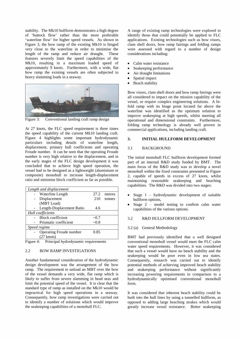
performance could be achieved largely by having finer
waterlines in the bow to reduce speed loss in waves, and
by raising the bow ramp far above the waterline to
minimise slamming occurrences. As part of the R&D
study, three hullforms were developed, denoted
‘Conventional’, ‘Hybrid’ and ‘Tri-bow’. Example
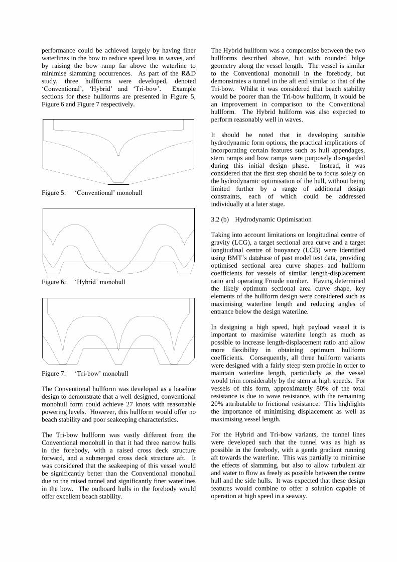
sections for these hullforms are presented in Figure 5,
Figure 6 and Figure 7 respectively.
Figure 5: ‘Conventional’ monohull
Figure 6: ‘Hybrid’ monohull
Figure 7: ‘Tri-bow’ monohull
The Conventional hullform was developed as a baseline
design to demonstrate that a well designed, conventional
monohull form could achieve 27 knots with reasonable
powering levels. However, this hullform would offer no
beach stability and poor seakeeping characteristics.
The Tri-bow hullform was vastly different from the
Conventional monohull in that it had three narrow hulls
in the forebody, with a raised cross deck structure
forward, and a submerged cross deck structure aft. It
was considered that the seakeeping of this vessel would
be significantly better than the Conventional monohull
due to the raised tunnel and significantly finer waterlines
in the bow. The outboard hulls in the forebody would
offer excellent beach stability.
The Hybrid hullform was a compromise between the two
hullforms described above, but with rounded bilge
geometry along the vessel length. The vessel is similar
to the Conventional monohull in the forebody, but
demonstrates a tunnel in the aft end similar to that of the
Tri-bow. Whilst it was considered that beach stability
would be poorer than the Tri-bow hullform, it would be
an improvement in comparison to the Conventional
hullform. The Hybrid hullform was also expected to
perform reasonably well in waves.
It should be noted that in developing suitable
hydrodynamic form options, the practical implications of
incorporating certain features such as hull appendages,
stern ramps and bow ramps were purposely disregarded
during this initial design phase. Instead, it was
considered that the first step should be to focus solely on
the hydrodynamic optimisation of the hull, without being
limited further by a range of additional design
constraints, each of which could be addressed
individually at a later stage.
3.2 (b) Hydrodynamic Optimisation
Taking into account limitations on longitudinal centre of
gravity (LCG), a target sectional area curve and a target
longitudinal centre of buoyancy (LCB) were identified
using BMT’s database of past model test data, providing
optimised sectional area curve shapes and hullform
coefficients for vessels of similar length-displacement
ratio and operating Froude number. Having determined
the likely optimum sectional area curve shape, key
elements of the hullform design were considered such as
maximising waterline length and reducing angles of
entrance below the design waterline.
In designing a high speed, high payload vessel it is
important to maximise waterline length as much as
possible to increase length-displacement ratio and allow
more flexibility in obtaining optimum hullform
coefficients. Consequently, all three hullform variants
were designed with a fairly steep stem profile in order to
maintain waterline length, particularly as the vessel
would trim considerably by the stern at high speeds. For
vessels of this form, approximately 80% of the total
resistance is due to wave resistance, with the remaining
20% attributable to frictional resistance. This highlights
the importance of minimising displacement as well as
maximising vessel length.
For the Hybrid and Tri-bow variants, the tunnel lines
were developed such that the tunnel was as high as
possible in the forebody, with a gentle gradient running
aft towards the waterline. This was partially to minimise
the effects of slamming, but also to allow turbulent air
and water to flow as freely as possible between the centre
hull and the side hulls. It was expected that these design
features would combine to offer a solution capable of
operation at high speed in a seaway.
Whilst all three hullform variants were very different in
appearance, each hullform was designed with identical
principal particulars and hydrostatic particulars including
length, breadth, draught, primary hull coefficients, LCB
position and sectional area shape. The conventional
hullform could therefore be used as an effective baseline
comparison for the other hullforms exhibiting varying
levels of beach stability.
3.3 R&D MODEL TESTING
The three hullform variants described in Section 3.2 were
tested in calm water at a model scale of 1:15. The tests
were conducted by BMT at the Haslar ship tank in
Gosport, UK.
The models were each tested with a deadweight of 65
tonnes (ATVP load) and at level trim. Runs were
performed at six speeds ranging from 12.5 knots to 27
knots, in order to build an accurate resistance curve for
each vessel.
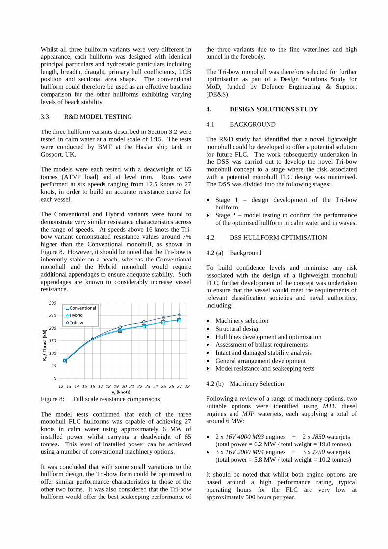
The Conventional and Hybrid variants were found to
demonstrate very similar resistance characteristics across
the range of speeds. At speeds above 16 knots the Tri-
bow variant demonstrated resistance values around 7%
higher than the Conventional monohull, as shown in
Figure 8. However, it should be noted that the Tri-bow is
inherently stable on a beach, whereas the Conventional
monohull and the Hybrid monohull would require
additional appendages to ensure adequate stability. Such
appendages are known to considerably increase vessel
resistance.
0
50
100
150
200
250
300
12 13 14 15 16 17 18 19 20 21 22 23 24 25 26 27 28
RT
/ Th
rust
(kN
)
Vs (knots)
Conventional
Hybrid
Tribow
Figure 8: Full scale resistance comparisons
The model tests confirmed that each of the three
monohull FLC hullforms was capable of achieving 27
knots in calm water using approximately 6 MW of
installed power whilst carrying a deadweight of 65
tonnes. This level of installed power can be achieved
using a number of conventional machinery options.
It was concluded that with some small variations to the
hullform design, the Tri-bow form could be optimised to
offer similar performance characteristics to those of the
other two forms. It was also considered that the Tri-bow
hullform would offer the best seakeeping performance of
the three variants due to the fine waterlines and high
tunnel in the forebody.
The Tri-bow monohull was therefore selected for further
optimisation as part of a Design Solutions Study for
MoD, funded by Defence Engineering & Support
(DE&S).
4. DESIGN SOLUTIONS STUDY
4.1 BACKGROUND
The R&D study had identified that a novel lightweight
monohull could be developed to offer a potential solution
for future FLC. The work subsequently undertaken in
the DSS was carried out to develop the novel Tri-bow
monohull concept to a stage where the risk associated
with a potential monohull FLC design was minimised.
The DSS was divided into the following stages:
Stage 1 – design development of the Tri-bow
hullform,
Stage 2 – model testing to confirm the performance
of the optimised hullform in calm water and in waves.
4.2 DSS HULLFORM OPTIMISATION
4.2 (a) Background
To build confidence levels and minimise any risk
associated with the design of a lightweight monohull
FLC, further development of the concept was undertaken
to ensure that the vessel would meet the requirements of
relevant classification societies and naval authorities,
including:
Machinery selection
Structural design
Hull lines development and optimisation
Assessment of ballast requirements
Intact and damaged stability analysis
General arrangement development
Model resistance and seakeeping tests
4.2 (b) Machinery Selection
Following a review of a range of machinery options, two
suitable options were identified using MTU diesel
engines and MJP waterjets, each supplying a total of
around 6 MW:
2 x 16V 4000 M93 engines + 2 x J850 waterjets
(total power = 6.2 MW / total weight = 19.8 tonnes)
3 x 16V 2000 M94 engines + 3 x J750 waterjets
(total power = 5.8 MW / total weight = 10.2 tonnes)
It should be noted that whilst both engine options are
based around a high performance rating, typical
operating hours for the FLC are very low at
approximately 500 hours per year.
Although significantly heavier than the three engine
option, the two engine option offered a higher installed
power than the three engine option, and it was expected
that a more efficient hullform could be developed around
the two engine layout by increasing the waterline length
in-between the waterjets. However, it was generally
accepted that the three engine option offered clear
advantages over the two engine option, including:
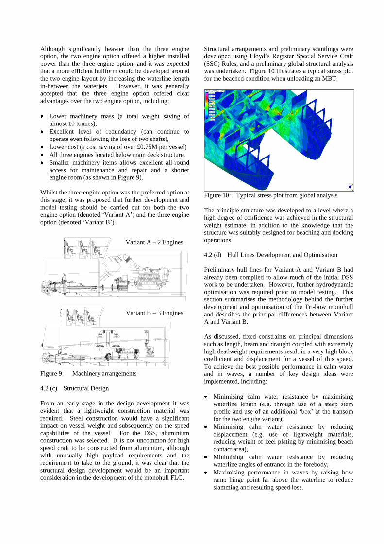
Lower machinery mass (a total weight saving of
almost 10 tonnes),
Excellent level of redundancy (can continue to
operate even following the loss of two shafts),
Lower cost (a cost saving of over £0.75M per vessel)
All three engines located below main deck structure,
Smaller machinery items allows excellent all-round
access for maintenance and repair and a shorter
engine room (as shown in Figure 9).
Whilst the three engine option was the preferred option at
this stage, it was proposed that further development and
model testing should be carried out for both the two
engine option (denoted ‘Variant A’) and the three engine
option (denoted ‘Variant B’).
Variant A - 2 Engines
Variant B - 3 Engines
Figure 9: Machinery arrangements
4.2 (c) Structural Design
From an early stage in the design development it was
evident that a lightweight construction material was
required. Steel construction would have a significant
impact on vessel weight and subsequently on the speed
capabilities of the vessel. For the DSS, aluminium
construction was selected. It is not uncommon for high
speed craft to be constructed from aluminium, although
with unusually high payload requirements and the
requirement to take to the ground, it was clear that the
structural design development would be an important
consideration in the development of the monohull FLC.
Structural arrangements and preliminary scantlings were
developed using Lloyd’s Register Special Service Craft
(SSC) Rules, and a preliminary global structural analysis
was undertaken. Figure 10 illustrates a typical stress plot
for the beached condition when unloading an MBT.
Figure 10: Typical stress plot from global analysis
The principle structure was developed to a level where a
high degree of confidence was achieved in the structural
weight estimate, in addition to the knowledge that the
structure was suitably designed for beaching and docking
operations.
4.2 (d) Hull Lines Development and Optimisation
Preliminary hull lines for Variant A and Variant B had
already been compiled to allow much of the initial DSS
work to be undertaken. However, further hydrodynamic
optimisation was required prior to model testing. This
section summarises the methodology behind the further
development and optimisation of the Tri-bow monohull
and describes the principal differences between Variant
A and Variant B.
As discussed, fixed constraints on principal dimensions
such as length, beam and draught coupled with extremely
high deadweight requirements result in a very high block
coefficient and displacement for a vessel of this speed.
To achieve the best possible performance in calm water
and in waves, a number of key design ideas were
implemented, including:
Minimising calm water resistance by maximising
waterline length (e.g. through use of a steep stem
profile and use of an additional ‘box’ at the transom
for the two engine variant),
Minimising calm water resistance by reducing
displacement (e.g. use of lightweight materials,
reducing weight of keel plating by minimising beach
contact area),
Minimising calm water resistance by reducing
waterline angles of entrance in the forebody,
Maximising performance in waves by raising bow
ramp hinge point far above the waterline to reduce
slamming and resulting speed loss.
Variant A – 2 Engines
Variant B – 3 Engines
It should be noted that whilst the Tri-bow hullform
demonstrates three bow forms in the forebody, the
tunnelled areas in this region reduce in depth (moving
aft) until the ‘wet deck’ is fully submerged.
Consequently, the vessel can be considered as a
monohull because there are no clear tunnels extending
throughout the length of the hull. Air cannot flow freely
from the bow to the stern beneath the hull, and
consequently a turbulent mix of air and water is
generated beneath the bow ramp.
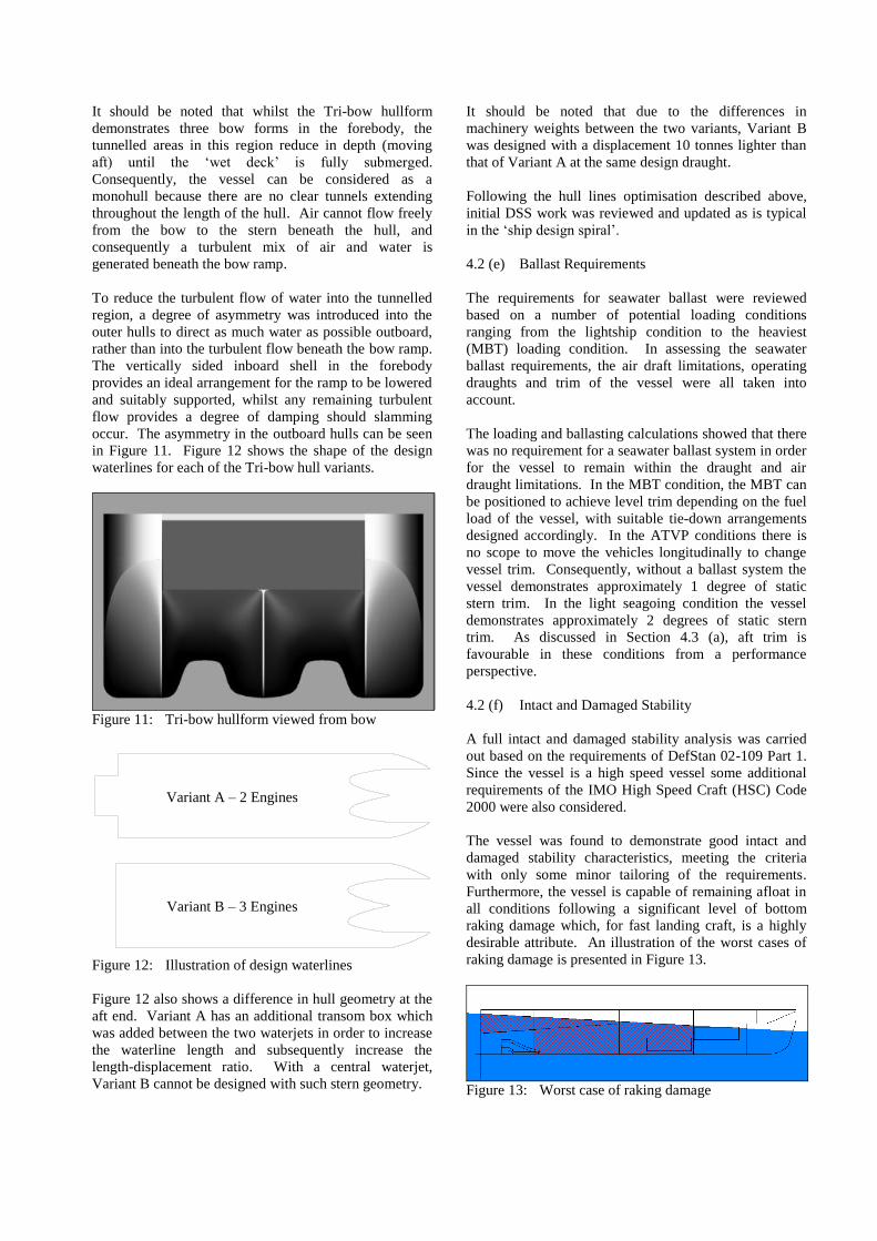
To reduce the turbulent flow of water into the tunnelled
region, a degree of asymmetry was introduced into the
outer hulls to direct as much water as possible outboard,
rather than into the turbulent flow beneath the bow ramp.
The vertically sided inboard shell in the forebody
provides an ideal arrangement for the ramp to be lowered
and suitably supported, whilst any remaining turbulent
flow provides a degree of damping should slamming
occur. The asymmetry in the outboard hulls can be seen
in Figure 11. Figure 12 shows the shape of the design
waterlines for each of the Tri-bow hull variants.
Figure 11: Tri-bow hullform viewed from bow
Figure 12: Illustration of design waterlines
Figure 12 also shows a difference in hull geometry at the
aft end. Variant A has an additional transom box which
was added between the two waterjets in order to increase
the waterline length and subsequently increase the
length-displacement ratio. With a central waterjet,
Variant B cannot be designed with such stern geometry.
It should be noted that due to the differences in
machinery weights between the two variants, Variant B
was designed with a displacement 10 tonnes lighter than
that of Variant A at the same design draught.
Following the hull lines optimisation described above,
initial DSS work was reviewed and updated as is typical
in the ‘ship design spiral’.
4.2 (e) Ballast Requirements
The requirements for seawater ballast were reviewed
based on a number of potential loading conditions
ranging from the lightship condition to the heaviest
(MBT) loading condition. In assessing the seawater
ballast requirements, the air draft limitations, operating
draughts and trim of the vessel were all taken into
account.
The loading and ballasting calculations showed that there
was no requirement for a seawater ballast system in order
for the vessel to remain within the draught and air
draught limitations. In the MBT condition, the MBT can
be positioned to achieve level trim depending on the fuel
load of the vessel, with suitable tie-down arrangements
designed accordingly. In the ATVP conditions there is
no scope to move the vehicles longitudinally to change
vessel trim. Consequently, without a ballast system the
vessel demonstrates approximately 1 degree of static
stern trim. In the light seagoing condition the vessel
demonstrates approximately 2 degrees of static stern
trim. As discussed in Section 4.3 (a), aft trim is
favourable in these conditions from a performance
perspective.
4.2 (f) Intact and Damaged Stability
A full intact and damaged stability analysis was carried
out based on the requirements of DefStan 02-109 Part 1.
Since the vessel is a high speed vessel some additional
requirements of the IMO High Speed Craft (HSC) Code
2000 were also considered.
The vessel was found to demonstrate good intact and
damaged stability characteristics, meeting the criteria
with only some minor tailoring of the requirements.
Furthermore, the vessel is capable of remaining afloat in
all conditions following a significant level of bottom
raking damage which, for fast landing craft, is a highly
desirable attribute. An illustration of the worst cases of
raking damage is presented in Figure 13.
Figure 13: Worst case of raking damage
Variant A – 2 Engines
Variant B – 3 Engines
4.2 (g) General Arrangement
General arrangement drawings for each variant of the
monohull FLC were initially developed at a basic level to
demonstrate capabilities with regard to payload and
space arrangements, including accommodation and
wheelhouse areas. Following the model tests described
in Section 4.3, the general arrangement for Variant B was
developed further at concept level as shown in Figure 14.
Figure 14: Monohull FLC general arrangement
4.3 DSS MODEL TESTING
4.3 (a) Calm Water Resistance Tests
In order to confirm the speed capabilities of the vessel in
calm water, a series of resistance tests was carried out on
both hull variants at a model scale of 1:10. The tests
were conducted at the Haslar ship tank in Gosport, UK.
The tests demonstrated that in calm water, both variants
were capable of achieving speeds in excess of the
requirements. However, Variant B was found to offer
better calm water performance and significantly higher
cavitation margins, even with operation on two engines.
Based on the results of the calm water resistance tests,
Variant B was identified as the favoured option,
particularly given the inherently high level of redundancy
and its ability to continue operation at high speed
following the loss of one shaft.
A small amount of stern trim was found to offer the
lowest hull resistance in the light and ATVP conditions.
Level trim or a small amount of bow down trim was
found to offer the lowest resistance in the MBT
condition. However, the effects on vessel resistance of
changing vessel trim were noted as being very small,
indicating that optimising the longitudinal distribution of
payload would not significantly influence vessel
resistance. This also suggests that the hullforms have
been designed with close to optimum LCB positions.
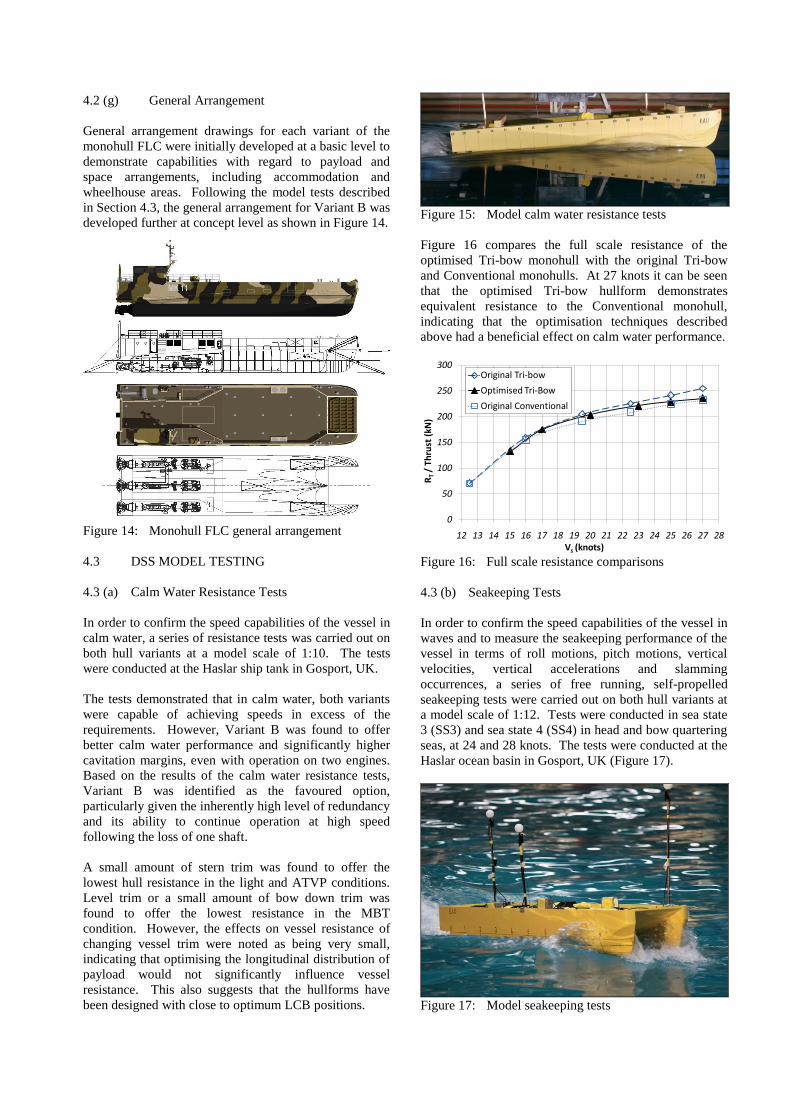
Figure 15: Model calm water resistance tests
Figure 16 compares the full scale resistance of the
optimised Tri-bow monohull with the original Tri-bow
and Conventional monohulls. At 27 knots it can be seen
that the optimised Tri-bow hullform demonstrates
equivalent resistance to the Conventional monohull,
indicating that the optimisation techniques described
above had a beneficial effect on calm water performance.
0
50
100
150
200
250
300
12 13 14 15 16 17 18 19 20 21 22 23 24 25 26 27 28
RT
/ T
hru
st (
kN)
Vs (knots)
Original Tri-bow
Optimised Tri-Bow
Original Conventional
Figure 16: Full scale resistance comparisons
4.3 (b) Seakeeping Tests
In order to confirm the speed capabilities of the vessel in
waves and to measure the seakeeping performance of the
vessel in terms of roll motions, pitch motions, vertical
velocities, vertical accelerations and slamming
occurrences, a series of free running, self-propelled
seakeeping tests were carried out on both hull variants at
a model scale of 1:12. Tests were conducted in sea state
3 (SS3) and sea state 4 (SS4) in head and bow quartering
seas, at 24 and 28 knots. The tests were conducted at the
Haslar ocean basin in Gosport, UK (Figure 17).
Figure 17: Model seakeeping tests
The tests demonstrated that in SS3, both variants of the
monohull were capable of achieving speeds in excess of
the requirements, with approximately 1 knot of speed
loss in seas of up to SS4. Variant B was found to offer
marginally less speed loss in waves, and therefore
remained the favoured variant.
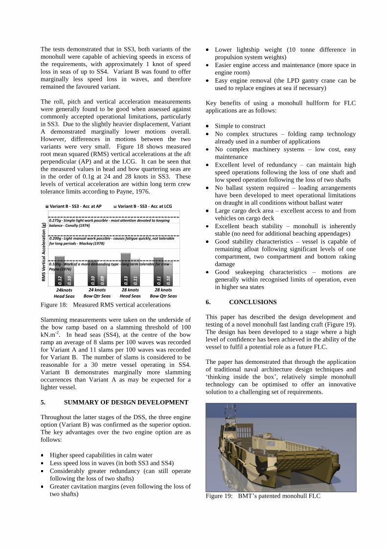
The roll, pitch and vertical acceleration measurements
were generally found to be good when assessed against
commonly accepted operational limitations, particularly
in SS3. Due to the slightly heavier displacement, Variant
A demonstrated marginally lower motions overall.
However, differences in motions between the two
variants were very small. Figure 18 shows measured
root mean squared (RMS) vertical accelerations at the aft
perpendicular (AP) and at the LCG. It can be seen that
the measured values in head and bow quartering seas are
in the order of 0.1g at 24 and 28 knots in SS3. These
levels of vertical acceleration are within long term crew
tolerance limits according to Payne, 1976.
0.1
2
0.1
0
0.1
3
0.1
1
0.1
0
0.0
9
0.1
1
0.1
0
RM
S V
ert
ica
l Acc
ele
rati
on
(g)
Variant B - SS3 - Acc at AP Variant B - SS3 - Acc at LCG
0.275g - Simple light work possible - most attention devoted to keeping balance - Conolly (1974)
0.200g - Light manual work possible - causes fatigue quickly, not tolerable for long periods - Mackay (1978)
0.100g - Work of a more demanding type - long term tolerable for crew -Payne (1976)
24knotsHead Seas
24 knotsBow Qtr Seas
28 knotsHead Seas
28 knotsBow Qtr Seas
Figure 18: Measured RMS vertical accelerations
Slamming measurements were taken on the underside of
the bow ramp based on a slamming threshold of 100
kN.m-2
. In head seas (SS4), at the centre of the bow
ramp an average of 8 slams per 100 waves was recorded
for Variant A and 11 slams per 100 waves was recorded
for Variant B. The number of slams is considered to be
reasonable for a 30 metre vessel operating in SS4.
Variant B demonstrates marginally more slamming
occurrences than Variant A as may be expected for a
lighter vessel.
5. SUMMARY OF DESIGN DEVELOPMENT
Throughout the latter stages of the DSS, the three engine
option (Variant B) was confirmed as the superior option.
The key advantages over the two engine option are as
follows:
Higher speed capabilities in calm water
Less speed loss in waves (in both SS3 and SS4)
Considerably greater redundancy (can still operate
following the loss of two shafts)
Greater cavitation margins (even following the loss of
two shafts)
Lower lightship weight (10 tonne difference in
propulsion system weights)
Easier engine access and maintenance (more space in
engine room)
Easy engine removal (the LPD gantry crane can be
used to replace engines at sea if necessary)
Key benefits of using a monohull hullform for FLC
applications are as follows:
Simple to construct
No complex structures – folding ramp technology
already used in a number of applications
No complex machinery systems – low cost, easy
maintenance
Excellent level of redundancy – can maintain high
speed operations following the loss of one shaft and
low speed operation following the loss of two shafts
No ballast system required – loading arrangements
have been developed to meet operational limitations
on draught in all conditions without ballast water
Large cargo deck area – excellent access to and from
vehicles on cargo deck
Excellent beach stability – monohull is inherently
stable (no need for additional beaching appendages)
Good stability characteristics – vessel is capable of
remaining afloat following significant levels of one
compartment, two compartment and bottom raking
damage
Good seakeeping characteristics – motions are
generally within recognised limits of operation, even
in higher sea states
6. CONCLUSIONS
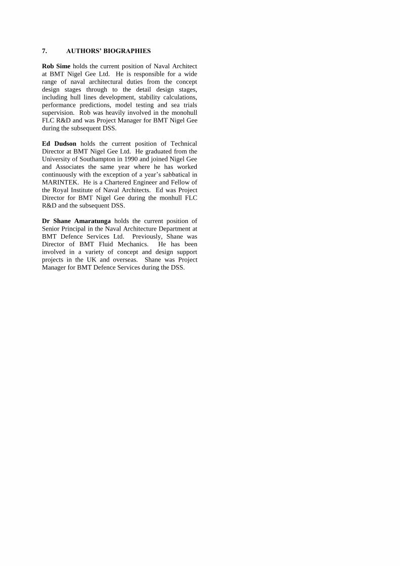
This paper has described the design development and
testing of a novel monohull fast landing craft (Figure 19).
The design has been developed to a stage where a high
level of confidence has been achieved in the ability of the
vessel to fulfil a potential role as a future FLC.
The paper has demonstrated that through the application
of traditional naval architecture design techniques and
‘thinking inside the box’, relatively simple monohull
technology can be optimised to offer an innovative
solution to a challenging set of requirements.
Figure 19: BMT’s patented monohull FLC
7. AUTHORS’ BIOGRAPHIES
Rob Sime holds the current position of Naval Architect
at BMT Nigel Gee Ltd. He is responsible for a wide
range of naval architectural duties from the concept
design stages through to the detail design stages,
including hull lines development, stability calculations,
performance predictions, model testing and sea trials
supervision. Rob was heavily involved in the monohull
FLC R&D and was Project Manager for BMT Nigel Gee
during the subsequent DSS.
Ed Dudson holds the current position of Technical
Director at BMT Nigel Gee Ltd. He graduated from the
University of Southampton in 1990 and joined Nigel Gee
and Associates the same year where he has worked
continuously with the exception of a year’s sabbatical in
MARINTEK. He is a Chartered Engineer and Fellow of
the Royal Institute of Naval Architects. Ed was Project
Director for BMT Nigel Gee during the monhull FLC
R&D and the subsequent DSS.
Dr Shane Amaratunga holds the current position of
Senior Principal in the Naval Architecture Department at
BMT Defence Services Ltd. Previously, Shane was
Director of BMT Fluid Mechanics. He has been
involved in a variety of concept and design support
projects in the UK and overseas. Shane was Project
Manager for BMT Defence Services during the DSS.