Embed Size (px)
Citation preview

ThinkCentre M93zHardware Maintenance Manual
Machine Types: 10AC, 10AD, 10AE and 10AF
Note: Before using this information and the product it supports, be sure to read and understand Chapter 2Safety information on page 3 and Appendix A Notices on page 133.
First Edition (June 2013)
Copyright Lenovo 2013.
LIMITED AND RESTRICTED RIGHTS NOTICE: If data or software is delivered pursuant a General Services AdministrationGSA contract, use, reproduction, or disclosure is subject to restrictions set forth in Contract No. GS-35F-05925.
Contents
Chapter 1. About this manual . . . . . . 1Important Safety Information . . . . . . . . . . 1
Chapter 2. Safety information. . . . . . 3General safety . . . . . . . . . . . . . . . . 3Electrical safety . . . . . . . . . . . . . . . 3Safety inspection guide . . . . . . . . . . . . 5Handling electrostatic discharge-sensitivedevices . . . . . . . . . . . . . . . . . . 5Grounding requirements . . . . . . . . . . . . 6Tip-over hazard prevention notice . . . . . . . . 6Safety notices (multi-lingual translations) . . . . . 6
Chapter 3. General information . . . . 29Speci cations . . . . . . . . . . . . . . . 29Lenovo programs . . . . . . . . . . . . . 30
Accessing Lenovo programs on the Windows7 operating system . . . . . . . . . . . 30Accessing Lenovo programs on the Windows8 operating system . . . . . . . . . . . 31
Lenovo Support Web site . . . . . . . . . . 31
Chapter 4. General checkout . . . . . 33Problem determination tips . . . . . . . . . . 33
Chapter 5. Troubleshooting anddiagnostics . . . . . . . . . . . . . . 35Basic troubleshooting . . . . . . . . . . . . 35Accessing Control Panel on the Windows 8operating system. . . . . . . . . . . . . . 35Troubleshooting procedure . . . . . . . . . . 36Troubleshooting . . . . . . . . . . . . . . 36
Audio problems . . . . . . . . . . . . 37CD problems . . . . . . . . . . . . . 38DVD problems . . . . . . . . . . . . . 39Intermittent problems . . . . . . . . . . 41Hard disk drive problems. . . . . . . . . 41Keyboard, mouse, or pointing deviceproblems . . . . . . . . . . . . . . . 41Monitor problems. . . . . . . . . . . . 44Networking problems . . . . . . . . . . 45Option problems . . . . . . . . . . . . 48Performance and lockup problems . . . . . 49Printer problems . . . . . . . . . . . . 51Serial port problems. . . . . . . . . . . 51Software problems . . . . . . . . . . . 52USB problems . . . . . . . . . . . . . 53
Diagnostics . . . . . . . . . . . . . . . . 53
Lenovo Solution Center . . . . . . . . . 53
Chapter 6. Using the Setup Utilityprogram . . . . . . . . . . . . . . . . 55Starting the Setup Utility program . . . . . . . 55Viewing and changing settings . . . . . . . . 55Using passwords. . . . . . . . . . . . . . 55
Password considerations . . . . . . . . . 56Power-On Password . . . . . . . . . . 56Administrator Password . . . . . . . . . 56Hard Disk Password. . . . . . . . . . . 56Setting, changing, and deleting a password . 56Erasing lost or forgotten passwords (clearingCMOS) . . . . . . . . . . . . . . . . 57
Enabling or disabling a device . . . . . . . . 57Selecting a startup device . . . . . . . . . . 58
Selecting a temporary startup device . . . . 58Selecting or changing the startup devicesequence . . . . . . . . . . . . . . . 58
Enabling ErP compliance mode . . . . . . . . 58ICE performance mode . . . . . . . . . . . 59ICE thermal alert . . . . . . . . . . . . . . 59Changing the BIOS settings before installing a newoperating system. . . . . . . . . . . . . . 60Exiting the Setup Utility program . . . . . . . 60
Chapter 7. Symptom-to-FRU index . . 61Hard disk drive boot error . . . . . . . . . . 61Power Supply Problems . . . . . . . . . . . 61Beep symptoms . . . . . . . . . . . . . . 61POST error codes . . . . . . . . . . . . . 62Miscellaneous error conditions . . . . . . . . 63Undetermined problems . . . . . . . . . . . 65
Chapter 8. Locations . . . . . . . . . 67Locating connectors, controls, and indicators onthe front of your computer . . . . . . . . . . 67
Using your computer in monitor mode . . . 68Accessing the On Screen Display (OSD) . . . 68
Locating connectors on the rear of yourcomputer . . . . . . . . . . . . . . . . . 70Locating major FRUs and CRUs . . . . . . . . 71Looking up FRU information . . . . . . . . . 74Locating parts on the system board . . . . . . 74Adjusting the frame stand . . . . . . . . . . 76Adjusting the monitor stand . . . . . . . . . 77Machine type and model label . . . . . . . . 79
Copyright Lenovo 2013 i
Chapter 9. Replacing FRUs . . . . . . 81Handling static-sensitive devices . . . . . . . 81Installing or replacing hardware . . . . . . . . 81
Installing external options . . . . . . . . 81Installing the monitor stand . . . . . . . . 82Removing the computer cover. . . . . . . 84Removing and reinstalling the frame foot . . 85Removing and reinstalling the rear I/Oassembly . . . . . . . . . . . . . . . 86Installing or replacing a memory module . . . 87Replacing the hard disk drive . . . . . . . 88Replacing the optical drive . . . . . . . . 90Replacing the converter board. . . . . . . 91Replacing the heat sink . . . . . . . . . 92Replacing the microprocessor . . . . . . . 94Replacing the internal speakers . . . . . . 97Replacing the thermal sensor . . . . . . . 98Replacing the cover presence switch (alsocalled intrusion switch). . . . . . . . . . 100Replacing the integrated camera . . . . . . 103Replacing the WiFi card . . . . . . . . . 105Replacing the ambient light sensor . . . . . 106Replacing the card reader . . . . . . . . 107Replacing the mSATA solid-state drive or miniPCI Express x1 card. . . . . . . . . . . 108Replacing the ExpressCard . . . . . . . . 110Replacing the heat sink and fan assembly forGPU . . . . . . . . . . . . . . . . . 111Replacing the rear PS/2 connectors and serialport assembly . . . . . . . . . . . . . 113Replacing the battery . . . . . . . . . . 114Replacing the power supply assembly . . . 116
Replacing the microprocessor fan . . . . . 117Replacing the LCD panel . . . . . . . . . 119Replacing the system board . . . . . . . 120Replacing the touch panel control boards . . 123Replacing the power switch and control buttonboard . . . . . . . . . . . . . . . . 124Replacing the WiFi antennas . . . . . . . 125Completing the parts replacement . . . . . 127
Chapter 10. Additional ServiceInformation . . . . . . . . . . . . . 129Security features . . . . . . . . . . . . . . 129
Hardware controlled Passwords . . . . . . 129Operating system password . . . . . . . 129Vital product data. . . . . . . . . . . . 129
BIOS levels . . . . . . . . . . . . . . . . 129Flash update procedures . . . . . . . . . . 129Updating ( ashing) the BIOS from a disc . . . . 130Updating ( ashing) the BIOS from your operatingsystem. . . . . . . . . . . . . . . . . . 131Recovering from a POST/BIOS update failure . . 131Power management . . . . . . . . . . . . 132
Automatic con guration and power interface(ACPI) BIOS . . . . . . . . . . . . . . 132Automatic Power-on features . . . . . . . 132
Appendix A. Notices. . . . . . . . . 133Television output notice . . . . . . . . . . . 134European conformance CE mark . . . . . . . 134Trademarks . . . . . . . . . . . . . . . . 134
Index. . . . . . . . . . . . . . . . . 135
ii ThinkCentre M93zHardware Maintenance Manual
Chapter 1. About this manual
This manual provides service and reference information for ThinkCentre computers listed on the front cover.This manual is intended only for trained service personnel who are familiar with Lenovo computer products.
Before servicing a Lenovo computer product, be sure to read Important Safety Information on page 1.
Chapter 7 Symptom-to-FRU index on page 61 and Chapter 10 Additional Service Information on page129 are not speci c to any machine type. These chapters are applicable to all ThinkCentre computers.
For major FRU locations and Customer Replaceable Unit (CRU) identi cation, see Chapter 8 Locationson page 67.
For FRU replacement instructions, see Chapter 9 Replacing FRUs on page 81.
For FRU part numbers, go to:http:/www.lenovo.com/serviceparts-lookup
Important Safety InformationBe sure to read all caution and danger statements in this book before performing any of the instructions.
Veuillez lire toutes les consignes de type DANGER et ATTENTION du présent document avant d'exécuterles instructions.
Lesen Sie unbedingt alle Hinweise vom Typ "ACHTUNG" oder "VORSICHT" in dieser Dokumentation, bevorSie irgendwelche Vorgänge durchf hren
Leggere le istruzioni introdotte da ATTENZIONE e PERICOLO presenti nel manuale prima di eseguire unaqualsiasi delle istruzioni
Certi que-se de ler todas as instruç es de cuidado e perigo neste manual antes de executar qualqueruma das instruç es
Es importante que lea todas las declaraciones de precauci n y de peligro de este manual antes de seguirlas instrucciones.
Copyright Lenovo 2013 1

2 ThinkCentre M93zHardware Maintenance Manual
Chapter 2. Safety information
This chapter contains the safety information that you need to be familiar with before servicing a computer.
General safetyFollow these rules to ensure general safety:
Observe good housekeeping in the area of the machines during and after maintenance.
When lifting any heavy object:
1. Ensure you can stand safely without slipping.
2. Distribute the weight of the object equally between your feet.
3. Use a slow lifting force. Never move suddenly or twist when you attempt to lift.
4. Lift by standing or by pushing up with your leg muscles; this action removes the strain from themuscles in your back.Do not attempt to lift any objects that weigh more than 16 kg (35 lb) or objects that you think aretoo heavy for you.
Do not perform any action that causes hazards to the customer, or that makes the equipment unsafe.
Before you start the machine, ensure that other service representatives and the customer's personnel arenot in a hazardous position.
Place removed covers and other parts in a safe place, away from all personnel, while you are servicingthe machine.
Keep your tool case away from walk areas so that other people will not trip over it.
Do not wear loose clothing that can be trapped in the moving parts of a machine. Ensure that your sleevesare fastened or rolled up above your elbows. If your hair is long, fasten it.
Insert the ends of your necktie or scarf inside clothing or fasten it with a nonconductive clip, approximately8 centimeters (3 inches) from the end.
Do not wear jewelry, chains, metal-frame eyeglasses, or metal fasteners for your clothing.Remember: Metal objects are good electrical conductors.
Wear safety glasses when you are: hammering, drilling, soldering, cutting wire, attaching springs, usingsolvents, or working in any other conditions that might be hazardous to your eyes.
After service, reinstall all safety shields, guards, labels, and ground wires. Replace any safety devicethat is worn or defective.
Reinstall all covers correctly before returning the machine to the customer.
Electrical safety
CAUTION:Electrical current from power, telephone, and communication cables can be hazardous. To avoidpersonal injury or equipment damage, disconnect the attached power cords, telecommunicationsystems, networks, and modems before you open the computer covers, unless instructed otherwisein the installation and con guration procedures.
Observe the following rules when working on electrical equipment.
Copyright Lenovo 2013 3
Important: Use only approved tools and test equipment. Some hand tools have handles covered with a softmaterial that does not insulate you when working with live electrical currents. Many customers have, neartheir equipment, rubber oor mats that contain small conductive bers to decrease electrostatic discharges.Do not use this type of mat to protect yourself from electrical shock.
Find the room emergency power-off (EPO) switch, disconnecting switch, or electrical outlet. If an electricalaccident occurs, you can then operate the switch or unplug the power cord quickly.
Do not work alone under hazardous conditions or near equipment that has hazardous voltages.
Disconnect all power before:
Performing a mechanical inspection
Working near power supplies
Removing or installing Field Replaceable Units (FRUs)
Before you start to work on the machine, unplug the power cord. If you cannot unplug it, ask the customerto power-off the wall box that supplies power to the machine and to lock the wall box in the off position.
If you need to work on a machine that has exposed electrical circuits, observe the following precautions:
Ensure that another person, familiar with the power-off controls, is near you.Remember: Another person must be there to switch off the power, if necessary.
Use only one hand when working with powered-on electrical equipment; keep the other hand in yourpocket or behind your back.Remember: There must be a complete circuit to cause electrical shock. By observing the above rule,you may prevent a current from passing through your body.
When using a tester, set the controls correctly and use the approved probe leads and accessories forthat tester.
Stand on suitable rubber mats (obtained locally, if necessary) to insulate you from grounds such asmetal oor strips and machine frames.
Observe the special safety precautions when you work with very high voltages; these instructions are inthe safety sections of maintenance information. Use extreme care when measuring high voltages.
Regularly inspect and maintain your electrical hand tools for safe operational condition.
Do not use worn or broken tools and testers.
Never assume that power has been disconnected from a circuit. First, check that it has been powered-off.
Always look carefully for possible hazards in your work area. Examples of these hazards are moist oors,nongrounded power extension cables, power surges, and missing safety grounds.
Do not touch live electrical circuits with the re ective surface of a plastic dental mirror. The surface isconductive; such touching can cause personal injury and machine damage.
Do not service the following parts with the power on when they are removed from their normal operatingplaces in a machine:
Power supply units
Pumps
Blowers and fans
Motor generators
and similar units. (This practice ensures correct grounding of the units.)
If an electrical accident occurs:
Use caution; do not become a victim yourself.
Switch off power.
Send another person to get medical aid.
4 ThinkCentre M93zHardware Maintenance Manual
Safety inspection guideThe intent of this inspection guide is to assist you in identifying potentially unsafe conditions on theseproducts. Each machine, as it was designed and built, had required safety items installed to protect usersand service personnel from injury. This guide addresses only those items. However, good judgment shouldbe used to identify potential safety hazards due to attachment of features or options not covered by thisinspection guide.
If any unsafe conditions are present, you must determine how serious the apparent hazard could be andwhether you can continue without rst correcting the problem.
Consider these conditions and the safety hazards they present:
Electrical hazards, especially primary power (primary voltage on the frame can cause serious or fatalelectrical shock).
Explosive hazards, such as a damaged CRT face or bulging capacitor
Mechanical hazards, such as loose or missing hardware
The guide consists of a series of steps presented in a checklist. Begin the checks with the power off, andthe power cord disconnected.
Checklist:
1. Check exterior covers for damage (loose, broken, or sharp edges).
2. Power-off the computer. Disconnect the power cord.
3. Check the power cord for:
a. A third-wire ground connector in good condition. Use a meter to measure third-wire groundcontinuity for 0.1 ohm or less between the external ground pin and frame ground.
b. The power cord should be the appropriate type as speci ed in the parts listings.
c. Insulation must not be frayed or worn.
4. Remove the cover.
5. Check for any obvious alterations. Use good judgment as to the safety of any alterations.
6. Check inside the unit for any obvious unsafe conditions, such as metal lings, contamination, water orother liquids, or signs of re or smoke damage.
7. Check for worn, frayed, or pinched cables.
8. Check that the power-supply cover fasteners (screws or rivets) have not been removed or tampered with.
Handling electrostatic discharge-sensitive devicesAny computer part containing transistors or integrated circuits (ICs) should be considered sensitive toelectrostatic discharge (ESD). ESD damage can occur when there is a difference in charge between objects.Protect against ESD damage by equalizing the charge so that the machine, the part, the work mat, and theperson handling the part are all at the same charge.
Notes:
1. Use product-speci c ESD procedures when they exceed the requirements noted here.
2. Make sure that the ESD protective devices you use have been certi ed (ISO 9000) as fully effective.
When handling ESD-sensitive parts:
Keep the parts in protective packages until they are inserted into the product.
Avoid contact with other people while handling the part.
Chapter 2. Safety information 5
Wear a grounded wrist strap against your skin to eliminate static on your body.
Prevent the part from touching your clothing. Most clothing is insulative and retains a charge even whenyou are wearing a wrist strap.
Use the black side of a grounded work mat to provide a static-free work surface. The mat is especiallyuseful when handling ESD-sensitive devices.
Select a grounding system, such as those listed below, to provide protection that meets the speci cservice requirement.
Note: The use of a grounding system is desirable but not required to protect against ESD damage.
Attach the ESD ground clip to any frame ground, ground braid, or green-wire ground.
Use an ESD common ground or reference point when working on a double-insulated orbattery-operated system. You can use coax or connector-outside shells on these systems.
Use the round ground-prong of the ac plug on ac-operated computers.
Grounding requirementsElectrical grounding of the computer is required for operator safety and correct system function. Propergrounding of the electrical outlet can be veri ed by a certi ed electrician.
Tip-over hazard prevention noticePlace the computer on a sturdy and low base, or anchor the furniture and position the computer asfar back on the furniture as possible.
Keep remote controls, toys, and other items that might attract children off the computer.
Keep the computer, cables, and cords out of the reach of children.
Supervise children in rooms where these safety tips have not been followed.
Safety notices (multi-lingual translations)The caution and danger safety notices in this section are provided in the following languages:
English
Arabic
Brazilian/Portuguese
Chinese (simpli ed)
Chinese (traditional)
French
German
Hebrew
Italian
Korean
Spanish
6 ThinkCentre M93zHardware Maintenance Manual
DANGER
Electrical current from power, telephone and communication cables is hazardous.
To avoid a shock hazard:
Do not connect or disconnect any cables or perform installation, maintenance, or recon gurationof this product during an electrical storm.
Connect all power cords to a properly wired and grounded electrical outlet.
Connect to properly wired outlets any equipment that will be attached to this product.
When possible, use one hand only to connect or disconnect signal cables.
Never turn on any equipment when there is evidence of re, water, or structural damage.
Disconnect the attached power cords, telecommunications systems, networks, and modemsbefore you open the device covers, unless instructed otherwise in the installation and con gurationprocedures.
Connect and disconnect cables as described in the following tables when installing, moving, oropening covers on this product or attached devices.
To Connect To Disconnect
1. Turn everything OFF.
2. First, attach all cables to devices.
3. Attach signal cables to connectors.
4. Attach power cords to outlet.
5. Turn device ON.
1. Turn everything OFF.
2. First, remove power cords from outlet.
3. Remove signal cables from connectors.
4. Remove all cables from devices.
CAUTION:When replacing the lithium battery, use only Part Number 45C1566 or an equivalent type batteryrecommended by the manufacturer. If your system has a module containing a lithium battery, replaceit only with the same module type made by the same manufacturer. The battery contains lithium andcan explode if not properly used, handled, or disposed of. Do not:
Throw or immerse into water
Heat to more than 100 C (212 F)
Repair or disassemble
Dispose of the battery as required by local ordinances or regulations.
CAUTION:When laser products (such as CD-ROMs, DVD-ROM drives, ber optic devices, or transmitters) areinstalled, note the following:
Do not remove the covers. Removing the covers of the laser product could result in exposure tohazardous laser radiation. There are no serviceable parts inside the device.
Use of controls or adjustments or performance of procedures other than those speci ed hereinmight result in hazardous radiation exposure.
Chapter 2. Safety information 7
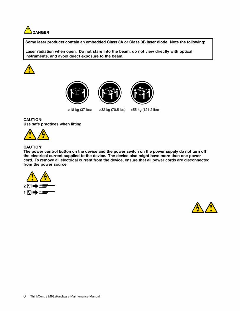
DANGER
Some laser products contain an embedded Class 3A or Class 3B laser diode. Note the following:
Laser radiation when open. Do not stare into the beam, do not view directly with opticalinstruments, and avoid direct exposure to the beam.
18 kg (37 lbs) 32 kg (70.5 lbs) 55 kg (121.2 lbs)
CAUTION:Use safe practices when lifting.
CAUTION:The power control button on the device and the power switch on the power supply do not turn offthe electrical current supplied to the device. The device also might have more than one powercord. To remove all electrical current from the device, ensure that all power cords are disconnectedfrom the power source.
1
2
8 ThinkCentre M93zHardware Maintenance Manual
Chapter 2. Safety information 9
18 kg (37 lbs) 32 kg (70.5 lbs) 55 kg (121.2 lbs)
1
2
PERIGO
A corrente elétrica proveniente de cabos de alimentação, de telefone e de comunicaç es é perigosa.
10 ThinkCentre M93zHardware Maintenance Manual
Para evitar risco de choque elétrico:
Não conecte nem desconecte nenhum cabo ou execute instalação, manutenção ou recon guraçãodeste produto durante uma tempestade com raios.
Conecte todos os cabos de alimentação a tomadas elétricas corretamente instaladas e aterradas.
Todo equipamento que for conectado a este produto deve ser conectado a tomadas corretamenteinstaladas.
Quando possível, utilize apenas uma das mãos para conectar ou desconectar cabos de sinal.
Nunca ligue nenhum equipamento quando houver evidência de fogo, água ou danos estruturais.
Antes de abrir tampas de dispositivos, desconecte cabos de alimentação, sistemas de telecomunicação,redes e modems conectados, a menos que especi cado de maneira diferente nos procedimentos deinstalação e con guração.
Conecte e desconecte os cabos conforme descrito na tabela apresentada a seguir ao instalar, mover ouabrir tampas deste produto ou de dispositivos conectados.
Para Conectar: Para Desconectar:
1. DESLIGUE Tudo.
2. Primeiramente, conecte todos os cabos aosdispositivos.
3. Conecte os cabos de sinal aos conectores.
4. Conecte os cabos de alimentação às tomadas.
5. LIGUE os dispositivos.
1. DESLIGUE Tudo.
2. Primeiramente, remova os cabos de alimentação dastomadas.
3. Remova os cabos de sinal dos conectores.
4. Remova todos os cabos dos dispositivos.
CUIDADO:
Ao substituir a bateria de lítio, utilize apenas uma bateria com N mero de Peça 45C1566 ou um tipode bateria equivalente recomendado pelo Se o seu sistema possui um m dulo com uma bateria delítio, substitua-o apenas por um m dulo do mesmo tipo e do mesmo fabricante. A bateria contém lítioe pode explodir se não for utilizada, manuseada ou descartada de maneira correta.
Não:
Jogue ou coloque na água
Aqueça a mais de 100 C (212 F)
Conserte nem desmonte
Descarte a bateria conforme requerido pelas leis ou regulamentos locais.
PRECAUCIÓN:
Quando produtos a laser (como unidades de CD-ROMs, unidades de DVD-ROM, dispositivos de bra ticaou transmissores) estiverem instalados, observe o seguinte:
Não remova as tampas. A remoção das tampas de um produto a laser pode resultar em exposiçãoprejudicial à radiação de laser. Não existem peças que podem ser consertadas no interior do dispositivo.
Chapter 2. Safety information 11
A utilização de controles ou ajustes ou a execução de procedimentos diferentes dos especi cados aquipode resultar em exposição prejudicial à radiação.
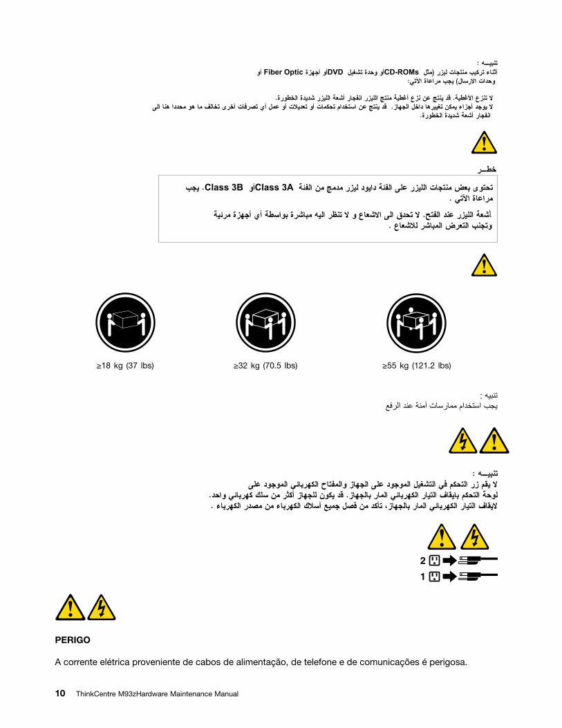
PERIGO
Alguns produtos a laser contêm diodo de laser integrado da Classe 3A ou da Classe 3B. Observe o seguinte:
Radiação a laser quando aberto. Não olhe diretamente para o feixe a olho nu ou com instrumentos pticos eevite exposição direta ao feixe.
18 kg (37 lbs) 32 kg (70.5 lbs) 55 kg (121.2 lbs)
CUIDADO:
Utilize procedimentos de segurança para levantar equipamentos.
CUIDADO:
O botão de controle de alimentação do dispositivo e o botão para ligar/desligar da fonte de alimentaçãonão desligam a corrente elétrica fornecida ao dispositivo. O dispositivo também pode ter mais de um cabode alimentação. Para remover toda a corrente elétrica do dispositivo, assegure que todos os cabos dealimentação estejam desconectados da fonte de alimentação.
1
2
12 ThinkCentre M93zHardware Maintenance Manual
Chapter 2. Safety information 13
1
2
14 ThinkCentre M93zHardware Maintenance Manual
1
2
Chapter 2. Safety information 15
DANGER
Le courant électrique provenant de l'alimentation, du téléphone et des câbles de transmission peut présenterun danger.
Pour éviter tout risque de choc électrique :
Ne manipulez aucun câble et n'effectuez aucune opération d'installation, d'entretien ou de recon gurationde ce produit au cours d'un orage.
Branchez tous les cordons d'alimentation sur un socle de prise de courant correctement câblé et mis à laterre.
Branchez sur des socles de prise de courant correctement câblés tout équipement connecté à ce produit.
Lorsque cela est possible, n'utilisez qu'une seule main pour connecter ou déconnecter les câblesd'interface.
Ne mettez jamais un équipement sous tension en cas d'incendie ou d'inondation, ou en présence dedommages matériels.
Avant de retirer les carters de l'unité, mettez celle-ci hors tension et déconnectez ses cordonsd'alimentation, ainsi que les câbles qui la relient aux réseaux, aux systèmes de télécommunication et auxmodems (sauf instruction contraire mentionnée dans les procédures d'installation et de con guration).
Lorsque vous installez, que vous déplacez, ou que vous manipulez le présent produit ou des périphériquesqui lui sont raccordés, reportez-vous aux instructions ci-dessous pour connecter et déconnecter lesdifférents cordons.
Connexion Déconnexion
1. Mettez les unités HORS TENSION.
2. Commencez par brancher tous les cordons sur lesunités.
3. Branchez les câbles d'interface sur des connecteurs.
4. Branchez les cordons d'alimentation sur des prises.
5. Mettez les unités SOUS TENSION.
1. Mettez les unités HORS TENSION.
2. Débranchez les cordons d'alimentation des prises.
3. Débranchez les câbles d'interface des connecteurs.
4. Débranchez tous les câbles des unités.
ATTENTION:
Remplacer la pile au lithium usagée par une pile de référence identique exclusivement, (référence45C1566), ou suivre les instructions du fabricant qui en dé nit les équivalences. Si votre système estdoté d'un module contenant une pile au lithium, vous devez le remplacer uniquement par un moduleidentique, produit par le même fabricant. La pile contient du lithium et peut exploser en cas demauvaise utilisation, de mauvaise manipulation ou de mise au rebut inappropriée.
Ne pas :
la jeter à l'eau,
l'exposer à des températures supérieures à 100 C,
chercher à la réparer ou à la démonter.
Ne pas mettre la pile à la poubelle. Pour la mise au rebut, se reporter à la réglementation en vigueur.
16 ThinkCentre M93zHardware Maintenance Manual
ATTENTION:
Si des produits à laser (tels que des unités de CD-ROM, de DVD-ROM, des unités à bres optiques, oudes émetteurs) sont installés, prenez connaissance des informations suivantes :
Ne retirez pas le carter. En ouvrant l'unité de CD-ROM ou de DVD-ROM, vous vous exposez aurayonnement dangereux du laser. Aucune pièce de l'unité n'est réparable.
Pour éviter tout risque d'exposition au rayon laser, respectez les consignes de réglage etd'utilisation des commandes, ainsi que les procédures décrites dans le présent manuel.
DANGER
Certains produits à laser contiennent une diode à laser intégrée de classe 3A ou 3B. Prenezconnaissance des informations suivantes:
Rayonnement laser lorsque le carter est ouvert. Evitez toute expositiondirecte au rayon laser. Evitezde regarder xement le faisceau ou del'observer à l'aide d'instruments optiques.
18 kg (37 lbs) 32 kg (70.5 lbs) 55 kg (121.2 lbs)
ATTENTION:
Soulevez la machine avec précaution.
ATTENTION:
L'interrupteur de contr le d'alimentation de l'unité et l'interrupteur dubloc d'alimentation ne coupentpas le courant électrique alimentantl'unité. En outre, le système peut être équipé de plusieurscordonsd'alimentation. Pour mettre l'unité hors tension, vous devez déconnectertous les cordonsde la source d'alimentation.
Chapter 2. Safety information 17
1
2
VORSICHT
An Netz-, Telefon- und Datenleitungen k nnen gefährliche Spannungen anliegen.
Aus Sicherheitsgr nden:
Bei Gewitter an diesem Gerät keine Kabel anschlie en oder l sen. Ferner keine Installations-,Wartungs- oder Rekon gurationsarbeiten durchf hren.
Gerät nur an eine Schutzkontaktsteckdose mit ordnungsgemä geerdetem Schutzkontaktanschlie en.
Alle angeschlossenen Geräte ebenfalls an Schutzkontaktsteckdosen mit ordnungsgemägeerdetem Schutzkontakt anschlie en.
Die Signalkabel nach M glichkeit einhändig anschlie en oder l sen, um einen Stromschlag durchBer hren von Ober ächen mit unterschiedlichem elektrischem Potenzial zu vermeiden.
Geräte niemals einschalten, wenn Hinweise auf Feuer, Wasser oder Gebäudeschäden vorliegen.
Die Verbindung zu den angeschlossenen Netzkabeln, Telekommunikationssystemen, Netzwerkenund Modems ist vor dem Öffnen des Gehäuses zu unterbrechen, sofern in den Installations- undKon gurationsprozeduren keine anders lautenden Anweisungen enthalten sind.
Zum Installieren, Transportieren und Öffnen der Abdeckungen des Computers oder derangeschlossenen Einheiten die Kabel gemä der folgenden Tabelle anschlie en und abziehen.
Zum Anschlie en der Kabel gehen Sie wie folgt vor Zum Abziehen der Kabel gehen Sie wie folgt vor
1. Schalten Sie alle Einheiten AUS.
2. Schlie en Sie erst alle Kabel an die Einheiten an.
3. Schlie en Sie die Signalkabel an die Buchsen an.
4. Schlie en Sie die Netzkabel an die Steckdose an.
5. Schalten Sie die Einheit EIN.
1. Schalten Sie alle Einheiten AUS.
2. Ziehen Sie zuerst alle Netzkabel aus denNetzsteckdosen.
3. Ziehen Sie die Signalkabel aus den Buchsen.
4. Ziehen Sie alle Kabel von den Einheiten ab.
CAUTION:
Eine verbrauchte Lithiumbatterie nur durch eine Batterie mit der Teilenummer 45C1566 oder einegleichwertige, vom Hersteller empfohlene Batterie ersetzen. Enthält das System ein Modul mit einerLithiumbatterie, dieses nur durch ein Modul desselben Typs und von demselben Hersteller ersetzen.Die Batterie enthält Lithium und kann bei unsachgemä er Verwendung, Handhabung oder Entsorgungexplodieren.
Die Batterie nicht:
mit Wasser in Ber hrung bringen.
18 ThinkCentre M93zHardware Maintenance Manual
ber 100 C erhitzen.
reparieren oder zerlegen.
Die rtlichen Bestimmungen f r die Entsorgung von Sonderm ll beachten.
ACHTUNG:
Bei der Installation von Lasergeräten (wie CD-ROM-Laufwerken, DVD- aufwerken, Einheiten mitLichtwellenleitertechnik oder Sendern) Folgendes beachten:
Die Abdeckungen nicht entfernen. Durch Entfernen der Abdeckungen des Lasergeräts k nnengefährliche Laserstrahlungen freigesetzt werden. Das Gerät enthält keine zu wartenden Teile.
Werden Steuerelemente, Einstellungen oder Durchf hrungen von Prozeduren anders als hierangegeben verwendet, kann gefährliche Laserstrahlung auftreten.
VORSICHT
Einige Lasergeräte enthalten eine Laserdiode der Klasse 3A oder 3B. Beachten Sie Folgendes:
Laserstrahlung bei ge ffneter Verkleidung. Nicht in den Strahl blicken. Keine Lupen oder Spiegelverwenden. Strahlungsbereich meiden.
18 kg 32 kg 55 kg
ACHTUNG:
Arbeitsschutzrichtlinien beim Anheben der Maschine beachten.
ACHTUNG:
Mit dem Netzschalter an der Einheit und am Netzteil wird die Stromversorgung f r die Einheitnicht unterbrochen. Die Einheit kann auch mit mehreren Netzkabeln ausgestattet sein. Um dieStromversorgung f r die Einheit vollständig zu unterbrechen, m ssen alle zum Gerät f hrendenNetzkabel vom Netz getrennt werden.
Chapter 2. Safety information 19
1
2
20 ThinkCentre M93zHardware Maintenance Manual
1
2
Chapter 2. Safety information 21
PERICOLO
La corrente elettrica proveniente dai cavi di alimentazione, del telefono e di comunicazione pu esserepericolosa.
Per evitare il rischio di scosse elettriche:
Non collegare o scollegare qualsiasi cavo oppure effettuare l'installazione, la manutenzione o laricon gurazione del prodotto durante un temporale.
Collegare tutti i li elettrici a una presa di alimentazione correttamente cablata e dotata di messa aterra.
Collegare alle prese elettriche appropriate tutte le apparecchiature che verranno utilizzate perquesto prodotto.
Se possibile, utilizzare solo una mano per collegare o scollegare i cavi di segnale.
Non accendere assolutamente apparecchiature in presenza di incendi, perdite d'acqua o dannostrutturale.
Scollegare i cavi di alimentazione, i sistemi di telecomunicazione, le reti e il modem prima diaprire i coperchi del dispositivo, salvo istruzioni contrarie relative alle procedure di installazione econ gurazione.
Collegare e scollegare i cavi come descritto nella seguente tabella quando vengono effettuateoperazioni di installazione, spostamento o apertura dei coperchi di questo prodotto o delle unitàcollegate.
Per collegarsi Per scollegarsi
1. SPEGNERE le apparecchiature.
2. Innanzitutto, collegare tutti i cavi alle unità.
3. Collegare i cavi di segnale ai connettori.
4. Collegare i cavi di alimentazione alla presa.
5. Accendere l'unità.
1. SPEGNERE le apparecchiature.
2. Innanzitutto, rimuovere i cavi di alimentazione dallapresa.
3. Rimuovere i cavi di segnale dai connettori.
4. Rimuovere tutti i cavi dalle unità.
ATTENZIONE:
Quando si sostituisce la batteria al litio, utilizzare solo il Numero parte 45C1566 o un tipo di batteriaequivalente consigliato dal produttore. Se sul sistema è presente un modulo che contiene una batteriaal litio, sostituirlo solo con un tipo di modulo dello stesso tipo della stessa casa di produzione. Labatteria contiene litio e pu esplodere se usata, maneggiata o smaltita in modo non corretto.
Non:
Gettare o immergere la batteria nell'acqua
Riscaldarla ad una temperatura superiore ai 100 gradi C (212 gradi F)
Smontarla, ricaricarla o tentare di ripararla
Le batterie usate vanno smaltite in accordo alla normativa in vigore (DPR 915/82 e successivedisposizioni e disposizioni locali).
22 ThinkCentre M93zHardware Maintenance Manual
ATTENZIONE:
Quando vengono installati prodotti laser (quali CD-ROM, unità DVD-ROM, unità a bre ottiche otrasmittenti), tener presente quanto segue:
Non rimuovere gli sportelli. L'apertura di un'unità laser pu determinare l'esposizione a radiazionilaser pericolose. All'interno dell'unità non vi sono parti su cui effettuare l'assistenza tecnica.
L'utilizzo di controlli, regolazioni o l'esecuzione di procedure non descritti nel presente manualepossono provocare l'esposizione a radiazioni pericolose.
PERICOLO
Alcune unità laser contengono un diodo laser di Classe 3A o Classe 3B. Tener presente quanto segue:
Aprendo l'unità vengono emesse radiazioni laser. Non ssare il fascio, non guardarlo direttamentecon strumenti ottici ed evitare l'esposizione al fascio.
18 kg 32 kg 55 kg
ATTENZIONE:
Prestare attenzione nel sollevare l'apparecchiatura.
ATTENZIONE:
Il pulsante di controllo dell'alimentazione presente sull'unità e l'interruttore dell'alimentatore nondisattivano l'alimentazione corrente fornita all'unità. E' possibile che l'unità disponga di pi cavi dialimentazione. Per disattivare l'alimentazione dall'unità, accertarsi che tutti i cavi di alimentazionesiano scollegati dalla fonte di alimentazione.
1
2
Chapter 2. Safety information 23
24 ThinkCentre M93zHardware Maintenance Manual
1
2
PELIGRO
La corriente eléctrica procedente de cables de alimentaci n, teléfonos y cables de comunicaci n puedeser peligrosa.
Para evitar el riesgo de descarga eléctrica:
No conecte ni desconecte los cables ni realice ninguna tarea de instalaci n, mantenimiento orecon guraci n de este producto durante una tormenta eléctrica.
Conecte todos los cables de alimentaci n a tomas de corriente debidamente cableadas yconectadas a tierra.
Cualquier equipo que se conecte a este producto también debe conectarse a tomas de corrientedebidamente cableadas.
Siempre que sea posible, utilice una sola mano para conectar o desconectar los cables de señal.
Chapter 2. Safety information 25
No encienda nunca un equipo cuando hay señales de fuego, agua o daños estructurales.
Desconecte los cables de alimentaci n, los sistemas de telecomunicaciones, las redes y losm dems conectados antes de abrir las cubiertas de los dispositivos, a menos que se indique locontrario en los procedimientos de instalaci n y con guraci n.
Conecte y desconecte los cables, como se describe en la tabla siguiente, cuando instale, mueva oabra las cubiertas de este producto o de los dispositivos conectados.
Para conectar Para desconectar
1. APÁGUELO todo.
2. En primer lugar, conecte todos los cables a losdispositivos.
3. Conecte los cables de señal a los conectores.
4. Enchufe los cables de alimentaci n a las tomas decorriente.
5. Encienda el dispositivo.
1. APÁGUELO todo.
2. En primer lugar, desenchufe los cables de alimentaci nde las tomas de corriente.
3. Desconecte los cables de señal de los conectores.
4. Desconecte todos los cables de los dispositivos.
PRECAUCIÓN:
Cuando sustituya una batería de litio, utilice solamente una batería n mero de pieza 45C1566 u otrade tipo equivalente recomendada por el fabricante. Si su sistema dispone de un m dulo que contieneuna batería de litio, reemplácelo s lo con el mismo tipo de m dulo, del mismo fabricante. La bateríacontiene litio y puede explotar si no se utiliza, manipula o desecha correctamente.
No debe:
Arrojarla al agua o sumergirla en ella
Exponerla a temperaturas superiores a 100 C (212 F)
Repararla o desmontarla
Deshágase de la batería seg n especi quen las leyes o normas locales.
PRECAUCIÓN:
Cuando haya productos láser (como unidades de CD-ROM, unidades de DVD, dispositivos de braptica o transmisores) instalados, tenga en cuenta lo siguiente:
No quite las cubiertas. Si quita las cubiertas del producto láser, podría quedar expuesto a radiaci nláser peligrosa. Dentro del dispositivo no existe ninguna pieza que requiera servicio técnico.
Si usa controles o ajustes o realiza procedimientos que no sean los especi cados aquí, podríaexponerse a radiaciones peligrosas.
PELIGRO
26 ThinkCentre M93zHardware Maintenance Manual
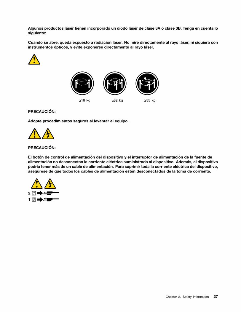
Algunos productos láser tienen incorporado un diodo láser de clase 3A o clase 3B. Tenga en cuenta losiguiente:
Cuando se abre, queda expuesto a radiaci n láser. No mire directamente al rayo láser, ni siquiera coninstrumentos pticos, y evite exponerse directamente al rayo láser.
18 kg 32 kg 55 kg
PRECAUCIÓN:
Adopte procedimientos seguros al levantar el equipo.
PRECAUCIÓN:
El bot n de control de alimentaci n del dispositivo y el interruptor de alimentaci n de la fuente dealimentaci n no desconectan la corriente eléctrica suministrada al dispositivo. Además, el dispositivopodría tener más de un cable de alimentaci n. Para suprimir toda la corriente eléctrica del dispositivo,aseg rese de que todos los cables de alimentaci n estén desconectados de la toma de corriente.
1
2
Chapter 2. Safety information 27

28 ThinkCentre M93zHardware Maintenance Manual
Chapter 3. General information
This chapter provides general information that applies to all machine types supported by this publication.
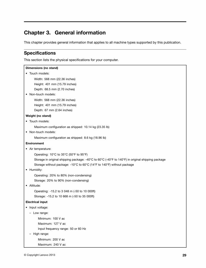
Speci cationsThis section lists the physical speci cations for your computer.
Dimensions (no stand)
Touch models:
Width: 568 mm (22.36 inches)
Height: 401 mm (15.79 inches)
Depth: 68.5 mm (2.70 inches)
Non-touch models:
Width: 568 mm (22.36 inches)
Height: 401 mm (15.79 inches)
Depth: 67 mm (2.64 inches)
Weight (no stand)
Touch models:
Maximum con guration as shipped: 10.14 kg (23.35 lb)
Non-touch models:
Maximum con guration as shipped: 8.6 kg (18.96 lb)
Environment
Air temperature:
Operating: 10 C to 35 C (50 F to 95 F)
Storage in original shipping package: -40 C to 60 C (-40 F to 140 F) in original shipping package
Storage without package: -10 C to 60 C (14 F to 140 F) without package
Humidity:
Operating: 20% to 80% (non-condensing)
Storage: 20% to 90% (non-condensing)
Altitude:
Operating: -15.2 to 3 048 m (-50 to 10 000ft)
Storage: -15.2 to 10 668 m (-50 to 35 000ft)
Electrical input
Input voltage:
Low range:
Minimum: 100 V ac
Maximum: 127 V ac
Input frequency range: 50 or 60 Hz
High range:
Minimum: 200 V ac
Maximum: 240 V ac
Copyright Lenovo 2013 29

Input frequency range: 50 or 60 Hz
Lenovo programsYour computer comes with Lenovo programs to help you work more easily and securely. Depending onthe Windows operating system preinstalled, the programs might vary.
Accessing Lenovo programs on the Windows 7 operating systemOn the Windows 7 operating system, you can access Lenovo programs from either the LenovoThinkVantage Tools program or from Control Panel.
Accessing Lenovo programs from the Lenovo ThinkVantage Tools program
To access Lenovo programs from the Lenovo ThinkVantage Tools program, click Start ᇆ All Programs ᇆLenovo ThinkVantage Tools. Then double-click a program icon to access the program.
Note: If a program icon in the Lenovo ThinkVantage Tools program navigation window is dimmed, itindicates that you need to install the program manually. To install the program manually, double-click theprogram icon. Then, follow the instructions on the screen. When the installation process completes, theprogram icon will be activated.
Table 1. Programs in the Lenovo ThinkVantage Tools program
Program Icon name
Communications Utility Web Conferencing
Fingerprint Software Fingerprint Reader
Lenovo Solution Center System Health and Diagnostics
Password Manager Password Vault
Power Manager Power Controls
Recovery Media Factory Recovery Disks
Rescue and Recovery Enhanced Backup and Restore
SimpleTap SimpleTap
System Update Update and Drivers
View Management Utility Screen Layout
Note: Depending on your computer model, some of the programs might not be available.
Accessing Lenovo programs from Control Panel
To access Lenovo programs from Control Panel, click Start ᇆ Control Panel. Then depending on theprogram you want to access, click the corresponding section and then click the corresponding green text.
Note: If you do not nd the program you need in Control Panel, open the Lenovo ThinkVantage Toolsprogram navigation window and double-click the dimmed icon to install the program you need. Then,follow the instructions on the screen. When the installation process completes, the program icon will beactivated, and you can nd the program in Control Panel.
The programs and the corresponding sections and green texts in Control Panel are listed in the followingtable.
30 ThinkCentre M93zHardware Maintenance Manual
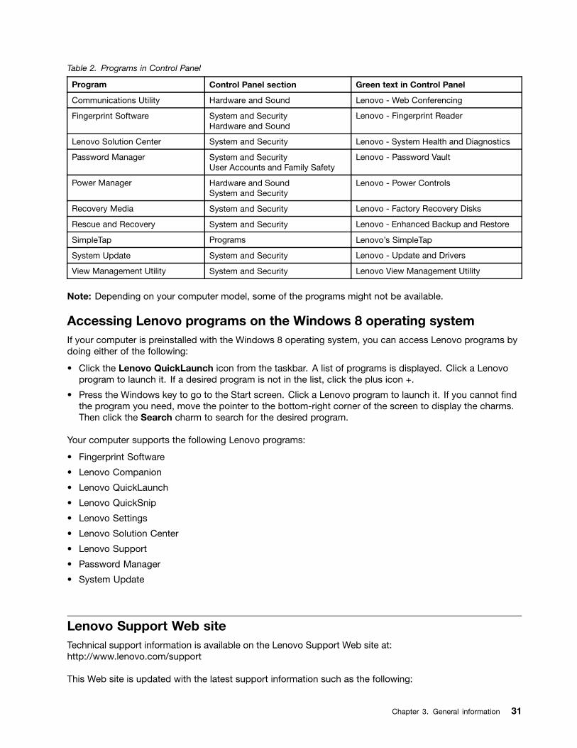
Table 2. Programs in Control Panel
Program Control Panel section Green text in Control Panel
Communications Utility Hardware and Sound Lenovo - Web Conferencing
Fingerprint Software System and SecurityHardware and Sound
Lenovo - Fingerprint Reader
Lenovo Solution Center System and Security Lenovo - System Health and Diagnostics
Password Manager System and SecurityUser Accounts and Family Safety
Lenovo - Password Vault
Power Manager Hardware and SoundSystem and Security
Lenovo - Power Controls
Recovery Media System and Security Lenovo - Factory Recovery Disks
Rescue and Recovery System and Security Lenovo - Enhanced Backup and Restore
SimpleTap Programs Lenovo s SimpleTap
System Update System and Security Lenovo - Update and Drivers
View Management Utility System and Security Lenovo View Management Utility
Note: Depending on your computer model, some of the programs might not be available.
Accessing Lenovo programs on the Windows 8 operating systemIf your computer is preinstalled with the Windows 8 operating system, you can access Lenovo programs bydoing either of the following:
Click the Lenovo QuickLaunch icon from the taskbar. A list of programs is displayed. Click a Lenovoprogram to launch it. If a desired program is not in the list, click the plus icon +.
Press the Windows key to go to the Start screen. Click a Lenovo program to launch it. If you cannot ndthe program you need, move the pointer to the bottom-right corner of the screen to display the charms.Then click the Search charm to search for the desired program.
Your computer supports the following Lenovo programs:
Fingerprint Software
Lenovo Companion
Lenovo QuickLaunch
Lenovo QuickSnip
Lenovo Settings
Lenovo Solution Center
Lenovo Support
Password Manager
System Update
Lenovo Support Web siteTechnical support information is available on the Lenovo Support Web site at:http://www.lenovo.com/support
This Web site is updated with the latest support information such as the following:
Chapter 3. General information 31

Drivers and software
Diagnostic solutions
Product and service warranty
Product and parts details
User guides and manuals
Knowledge base and frequently asked questions
32 ThinkCentre M93zHardware Maintenance Manual
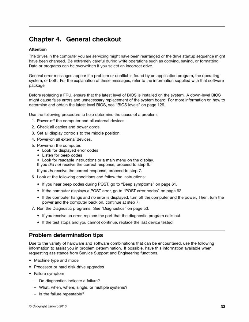
Chapter 4. General checkoutAttention
The drives in the computer you are servicing might have been rearranged or the drive startup sequence mighthave been changed. Be extremely careful during write operations such as copying, saving, or formatting.Data or programs can be overwritten if you select an incorrect drive.
General error messages appear if a problem or con ict is found by an application program, the operatingsystem, or both. For the explanation of these messages, refer to the information supplied with that softwarepackage.
Before replacing a FRU, ensure that the latest level of BIOS is installed on the system. A down-level BIOSmight cause false errors and unnecessary replacement of the system board. For more information on how todetermine and obtain the latest level BIOS, see BIOS levels on page 129.
Use the following procedure to help determine the cause of a problem:
1. Power-off the computer and all external devices.
2. Check all cables and power cords.
3. Set all display controls to the middle position.
4. Power-on all external devices.
5. Power-on the computer.Look for displayed error codesListen for beep codesLook for readable instructions or a main menu on the display.
If you did not receive the correct response, proceed to step 6.
If you do receive the correct response, proceed to step 7.
6. Look at the following conditions and follow the instructions:
If you hear beep codes during POST, go to Beep symptoms on page 61.
If the computer displays a POST error, go to POST error codes on page 62.
If the computer hangs and no error is displayed, turn off the computer and the power. Then, turn thepower and the computer back on, continue at step 7.
7. Run the Diagnostic programs. See Diagnostics on page 53.
If you receive an error, replace the part that the diagnostic program calls out.
If the test stops and you cannot continue, replace the last device tested.
Problem determination tipsDue to the variety of hardware and software combinations that can be encountered, use the followinginformation to assist you in problem determination. If possible, have this information available whenrequesting assistance from Service Support and Engineering functions.
Machine type and model
Processor or hard disk drive upgrades
Failure symptom
Do diagnostics indicate a failure?
What, when, where, single, or multiple systems?
Is the failure repeatable?
Copyright Lenovo 2013 33
Has this con guration ever worked?
If it has been working, what changes were made prior to it failing?
Is this the original reported failure?
Diagnostics version
Type and version level
Hardware con guration
Print (print screen) con guration currently in use
BIOS level
Operating system software
Type and version level
Notes: To eliminate confusion, identical systems are considered identical only if they:
1. Are the exact machine type and models
2. Have the same BIOS level
3. Have the same adapters/attachments in the same locations
4. Have the same address jumpers/terminators/cabling
5. Have the same software versions and levels
6. Have the same Diagnostic Diskettes (version)
7. Have the same con guration options set in the system
8. Have the same setup for the operating system control les
Comparing the con guration and software set-up between working and non-working systems will oftenlead to problem resolution.
34 ThinkCentre M93zHardware Maintenance Manual
Chapter 5. Troubleshooting and diagnostics
This chapter describes some basic troubleshooting and diagnostic programs. If your computer problem isnot described here, see Lenovo Support Web site on page 31 for additional troubleshooting resources.
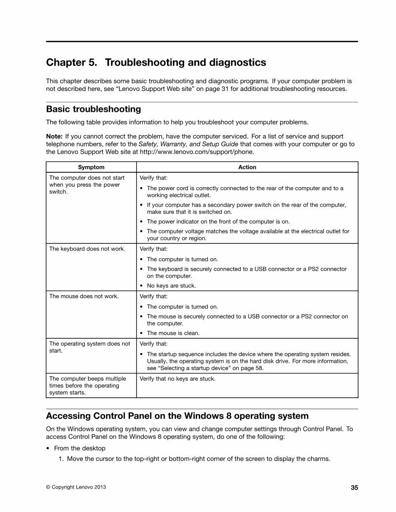
Basic troubleshootingThe following table provides information to help you troubleshoot your computer problems.
Note: If you cannot correct the problem, have the computer serviced. For a list of service and supporttelephone numbers, refer to the Safety, Warranty, and Setup Guide that comes with your computer or go tothe Lenovo Support Web site at http://www.lenovo.com/support/phone.
Symptom Action
The computer does not startwhen you press the powerswitch.
Verify that:
The power cord is correctly connected to the rear of the computer and to aworking electrical outlet.
If your computer has a secondary power switch on the rear of the computer,make sure that it is switched on.
The power indicator on the front of the computer is on.
The computer voltage matches the voltage available at the electrical outlet foryour country or region.
The keyboard does not work. Verify that:
The computer is turned on.
The keyboard is securely connected to a USB connector or a PS2 connectoron the computer.
No keys are stuck.
The mouse does not work. Verify that:
The computer is turned on.
The mouse is securely connected to a USB connector or a PS2 connector onthe computer.
The mouse is clean.
The operating system does notstart.
Verify that:
The startup sequence includes the device where the operating system resides.Usually, the operating system is on the hard disk drive. For more information,see Selecting a startup device on page 58.
The computer beeps multipletimes before the operatingsystem starts.
Verify that no keys are stuck.
Accessing Control Panel on the Windows 8 operating systemOn the Windows operating system, you can view and change computer settings through Control Panel. Toaccess Control Panel on the Windows 8 operating system, do one of the following:
From the desktop
1. Move the cursor to the top-right or bottom-right corner of the screen to display the charms.
Copyright Lenovo 2013 35
2. Click Settings.
3. Click Control Panel.
From the Start screen
1. Move the cursor to the top-right or bottom-right corner of the screen to display the charms.
2. Click Search.
3. On the Apps screen, scroll to the right side, and click Control Panel in the Windows System section.
Troubleshooting procedureUse the following procedure as a starting point for diagnosing problems you are experiencing with yourcomputer:
1. Verify that the cables for all attached devices are connected correctly and securely.
2. Verify that all attached devices that require ac power are connected to properly grounded, functioningelectrical outlets.
3. Verify that all attached devices are enabled in the BIOS settings of your computer. For more informationabout accessing and changing the BIOS settings, refer to your Chapter 6 Using the Setup Utilityprogram on page 55.
4. Go to the Troubleshooting on page 36 and follow the instructions for the type of problem you areexperiencing. If the Troubleshooting information does not help you resolve a problem, continue with thenext step.
5. Try using a previously captured con guration to see if a recent change to hardware or software settingshas caused a problem. Before restoring a previous con guration, capture your current con guration incase the older con guration settings do not solve the problem or have adverse affects. To restore acaptured con guration, do the following:
For Windows 7: Click Start ᇆ Control Panel ᇆ System and Security ᇆ System ᇆ SystemProtection ᇆ System Restore.
For Windows 8: Open Control Panel, and then click System and Security ᇆ System ᇆ SystemProtection ᇆ System Restore.
If this does not correct the problem, continue with the next step.
6. Run the diagnostic program. See Lenovo Solution Center on page 53 for more information.
If the diagnostic program detects a hardware failure, contact the Lenovo Customer Support Center.See Lenovo Support Web site on page 31 for more information.
If you are unable to run the diagnostic program, contact the Lenovo Customer Support Center. SeeLenovo Support Web site on page 31 for more information.
If the diagnostic program does not detect a hardware failure, continue with the next step.
7. Use an antivirus program to see if your computer has been infected by a virus. If the program detects avirus, remove the virus.
8. If none of these actions solve the problem, seek technical assistance. See Lenovo Support Website on page 31 for more information.
TroubleshootingUse the troubleshooting information to nd solutions to problems that have de nite symptoms.
If the symptom your computer is experiencing occurred immediately after you installed a new hardwareoption or new software, do the following before referring to the troubleshooting information:
1. Remove the new hardware option or software. If you must remove the computer cover to remove ahardware option, make sure you review and follow the electrical safety information provided with yourcomputer. For your safety, do not operate the computer with the cover removed.
36 ThinkCentre M93zHardware Maintenance Manual
2. Run the diagnostic programs to ensure your computer is operating correctly.
3. Reinstall the new hardware option or software following the manufacturer's instructions.
Select the problem your computer is experiencing from the following list:
Audio problems on page 37
CD problems on page 38
DVD problems on page 39
Intermittent problems on page 41
Hard disk drive problems on page 41
Keyboard, mouse, or pointing device problems on page 41
Networking problems on page 45
Option problems on page 48
Performance and lockup problems on page 49
Printer problems on page 51
Serial port problems on page 51
Software problems on page 52
USB problems on page 53
Audio problemsSelect your symptom from the following list:
No audio in Windows on page 37
An audio disc or AutoPlay-enabled disc does not automatically play when it is inserted into a driveon page 38
Sound comes from one external speaker only on page 38
No audio in DOS applications or games on page 38
No audio in WindowsSymptom: No audio in Windows
Actions:
If you are using powered external speakers that have an On/Off control, verify that the On/Off control isset to the On position and the speaker power cable is connected to a properly grounded, functional acelectrical outlet.
If your external speakers have a volume control, verify that the volume control is not set too low.
Double-click the speaker icon in the Windows noti cation area. A master volume-control window opens.Verify that the Mute settings are not checked and none of the volume settings is set too low.
Verify that your external speakers (and headphones, if used) are connected to the correct audio connectoron the computer. Most speaker cables are color-coded to match the connector.
Note: When external-speaker or headphone cables are attached to the audio connector, the internalspeaker, if present, is disabled. In most cases, if an audio adapter is installed in one of the expansion slots,the audio function built into the system board is disabled; use the audio jacks on the adapter.
Make sure that the program you are running is designed for use in the Microsoft Windows operatingsystem. If the program is designed to run in DOS, the program does not use the Windows sound featureand must be con gured to use SoundBlaster Pro or SoundBlaster emulation.
Chapter 5. Troubleshooting and diagnostics 37
Verify that the audio device drivers are correctly installed. See Microsoft Windows help system for moreinformation.
If these actions do not correct the problem, run the diagnostic programs (see Lenovo Solution Center onpage 53 for instructions). If you need technical assistance, see Lenovo Support Web site on page 31.
An audio disc or AutoPlay-enabled disc does not automatically play when it isinserted into a driveSymptom: An audio disc or AutoPlay-enabled disc does not automatically play when it is inserted into a drive
Action: See CD problems on page 38.
Sound comes from one external speaker onlySymptom: Sound comes from one external speaker only.
Actions:
Ensure that the speaker cable is inserted completely into the connector on the computer.
Make sure the cable that attaches the left speaker to the right speaker is securely connected.
Double-click the speaker icon in the Windows noti cation area. A master volume-control window opens.Verify that the Balance settings are set correctly.
If these actions do not correct the problem, you might have a failing speaker. Have the speaker serviced. Ifyou need technical assistance, see Lenovo Support Web site on page 31.
No audio in DOS applications or gamesSymptom: No audio in DOS applications or games
Actions:
Make sure the DOS application or game is con gured to use SoundBlaster Pro or SoundBlasteremulation. Refer to the documentation that comes with the application or game for instructions onsetting sound-card settings.
If these actions do not correct the problem, run the diagnostic programs (see Lenovo Solution Center onpage 53 for instructions). If you need technical assistance, see Lenovo Support Web site on page 31.
CD problemsSelect your symptom from the following list:
An audio disc or AutoPlay-enabled disc does not automatically play when it is inserted into a CDdrive on page 38
A CD or DVD does not work on page 39
Unable to use a startable (bootable) recovery medium, such as the Product Recovery CD, to startyour computer on page 39
An audio disc or AutoPlay-enabled disc does not automatically play when it isinserted into a CD driveSymptom: An audio disc or AutoPlay-enabled disc does not automatically play when it is inserted intoa CD drive.
Actions:
38 ThinkCentre M93zHardware Maintenance Manual
If you have multiple CD or DVD drives installed (or a combination of CD and DVD drives), try inserting thedisc into the other drive. In some cases, only one of the drives is connected to the audio subsystem.
If you are using the Windows 7 operating system, follow the action for A CD or DVD does not workon page 39.
If this does not correct the problem, follow the action for A CD or DVD does not work on page 39.
A CD or DVD does not workSymptom: A CD or DVD does not work.
Actions:
Verify that the disc is inserted correctly, with its label up.
Make sure that the disc you are using is clean. To remove dust or ngerprints, wipe the disc clean with asoft cloth from the center to the outside. Wiping a disc in a circular motion might cause loss of data.
Verify that the disc you are using is not scratched or damaged. Try inserting another disc that you knowis good. If you cannot read from a known-good disc, you might have a problem with your CD or DVDdrive or the cabling to your CD or DVD drive. Make sure that the power cable and signal cable aresecurely connected to the drive.
Unable to use a startable (bootable) recovery medium, such as the Product RecoveryCD, to start your computerSymptom: Unable to use a startable (bootable) recovery medium, such as the Product Recovery CD,to start your computer.
Action: Make sure that the CD or DVD drive is in the startup sequence before the hard disk drive. Referto your Selecting or changing the startup device sequence on page 58 for information on viewing andchanging the startup sequence. Note that on some models the startup sequence is permanently set andcannot be changed.
If these actions do not correct the problem, run the diagnostic programs (see Lenovo Solution Center onpage 53 for instructions). If you need technical assistance, see Lenovo Support Web site on page 31.
DVD problemsSelect your symptom from the following list:
Black screen instead of DVD video on page 39
DVD movie will not play on page 40
No audio or intermittent audio while playing DVD movie on page 40
Playback is very slow or choppy on page 40
Invalid disc or no disc found message on page 40
Black screen instead of DVD videoSymptom: Black screen instead of DVD video
Actions:
Restart the DVD player program.
Close any open les, turn off the computer, and then restart the computer.
Try a lower screen resolution or color depth.
Chapter 5. Troubleshooting and diagnostics 39
If these actions do not correct the problem, run the diagnostic programs (see Lenovo Solution Center onpage 53 for instructions). If you need technical assistance, see Lenovo Support Web site on page 31.
DVD movie will not playSymptom: DVD movie will not play.
Actions:
Make sure that the disc surface is clean and not scratched.
Check the disc or package for regional coding. You might need to purchase a disc with coding forthe region where you are using your computer.
If these actions do not correct the problem, run the diagnostic programs (see Lenovo Solution Center onpage 53 for instructions). If you need technical assistance, see Lenovo Support Web site on page 31.
No audio or intermittent audio while playing DVD movieSymptom: No audio or intermittent audio while playing DVD movie.
Actions:
Check the volume control settings on your computer and on your speakers.
Make sure that the disc surface is clean and not scratched.
Check all cable connections to and from the speakers.
Use the DVD menu for the video to select a different audio track.
If these actions do not correct the problem, run the diagnostic programs (see Lenovo Solution Center onpage 53 for instructions). If you need technical assistance, see Lenovo Support Web site on page 31.
Playback is very slow or choppySymptom: Playback is very slow or choppy.
Actions:
Disable any background programs, such as AntiVirus or Desktop Themes.
Ensure that video resolution is set to less than 1152 x 864.
If these actions do not correct the problem, run the diagnostic programs (see Lenovo Solution Center onpage 53 for instructions). If you need technical assistance, see Lenovo Support Web site on page 31.
Invalid disc or no disc found messageSymptom: Invalid disc or no disc found message
Actions:
Ensure that a DVD disc is in the drive with the shiny side of the disc facing down.
Ensure that video resolution is set to less than 1152 x 864.
On computers that have a CD-ROM or CD-RW drive in addition to a DVD-ROM drive, make sure that theDVD disc is in the drive labeled DVD .
If these actions do not correct the problem, run the diagnostic programs (see Lenovo Solution Center onpage 53 for instructions). If you need technical assistance, see Lenovo Support Web site on page 31.
40 ThinkCentre M93zHardware Maintenance Manual
Intermittent problemsSymptom: A problem occurs only occasionally and is dif cult to repeat.
Actions:
Verify that all cables and cords are securely connected to the computer and attached devices.
Verify that when the computer is on, the fan grill is not blocked (there is air ow around the grill), and thefans are working. If air ow is blocked or the fans are not working, the computer might overheat.
If these actions do not correct the problem, run the diagnostic programs (see Lenovo Solution Center onpage 53 for instructions). If you need technical assistance, see Lenovo Support Web site on page 31.
Hard disk drive problemsSelect your symptom from the following list:
Some or all hard disk drives missing from the Setup Utility program on page 41
"No Operating System Found" message or the system not starting from the correct hard disk driveon page 41
Some or all hard disk drives missing from the Setup Utility programSymptom: Some or all hard disk drives missing from the Setup Utility program
Actions:
Ensure that all hard disk drive signal cables and power cables are connected correctly.
Ensure that your computer is con gured correctly to support the hard disk drives.
If your computer is installed with ve SATA hard disk drives, ensure that the SATA hard disk driveenablement module (one to ve hard disk drives) is installed.
If your computer is installed with SAS hard disk drives, ensure that the SAS hard disk drive enablementmodule (one to ve hard disk drives) or the LSI MegaRAID SAS adapter is installed.
If these actions do not correct the problem, run the diagnostic program Lenovo Solution Center. See LenovoSolution Center on page 53. If you need technical assistance, see Lenovo Support Web site on page 31.
"No Operating System Found" message or the system not starting from the correcthard disk driveSymptom: "No Operating System Found" message or the system not starting from the correct hard disk drive
Actions:
Ensure that all hard disk drive signal cables and power cables are connected correctly.
Ensure that the hard disk drive your computer starts from is listed as the rst startup device in the SetupUtility program. Refer to Selecting a startup device on page 58.
Note: In rare cases, the hard disk drive with the operating system might get corrupted or damaged. In suchcases, you might need to replace the hard disk drive.
If these actions do not correct the problem, run the diagnostic program Lenovo Solution Center. See LenovoSolution Center on page 53. If you need technical assistance, see Lenovo Support Web site on page 31.
Keyboard, mouse, or pointing device problemsSelect your symptom from the following list:
Chapter 5. Troubleshooting and diagnostics 41
All or some keys on the keyboard do not work on page 42
The mouse or pointing device does not work on page 42
The pointer on the screen does not move smoothly with the mouse on page 43
The ngerprint reader does not work on page 43
The wireless keyboard does not work on page 43
All or some keys on the keyboard do not workSymptom: All or some keys on the keyboard do not work.
Actions:
Verify that the keyboard cable is securely connected to the correct connector on the computer.
If you are using an Enhanced Performance USB keyboard and one or more of the Rapid Access buttonsare the only keys that are not working, these buttons might have been disabled or have not been assignedto a function. Use the help system in the Enhanced Performance Customization Keyboard program tohelp diagnose problems with the Rapid Access buttons.
To open the Enhanced Performance Customization Keyboard program, do one of the following:
On the Windows 7 operating system, do the following:
1. Click Start ᇆ Control Panel.
2. Click Hardware and Sound.
3. Click Devices and Printers.
4. Double-click USB Enhanced Performance Keyboard. The USB Enhanced PerformanceKeyboard Customization program starts.
On the Windows 8 operating system, do the following:
1. Open Control Panel.
2. Click Hardware and Sound.
3. Click Devices and Printers.
4. Double-click USB Enhanced Performance Keyboard. The USB Enhanced PerformanceKeyboard Customization program starts.
If these actions do not correct the problem, have the computer and keyboard serviced. See LenovoSupport Web site on page 31 for details.
The mouse or pointing device does not workSymptom: The mouse or pointing device does not work.
Actions:
Verify that the mouse or pointing-device cable is securely attached to the correct connector on thecomputer. Depending on the type of mouse you have, the mouse cable will connect to either themouse, serial, or USB connector. Some keyboards have integrated USB connectors that can be usedfor a USB mouse or pointing device.
Verify that the device drivers for the mouse or pointing device are installed correctly.
If you are using a USB keyboard or mouse, verify that the USB connectors are enabled in the BIOSsettings. See Enabling or disabling a device on page 57.
If these actions do not correct the problem, run the diagnostic programs (see Lenovo Solution Center onpage 53 for instructions). If you need technical assistance, see Lenovo Support Web site on page 31.
42 ThinkCentre M93zHardware Maintenance Manual
Optical mouseThis section provides instructions on how to clean an optical mouse.
An optical mouse uses a light-emitting diode (LED) and an optical sensor to navigate the pointer. If thepointer on the screen does not move smoothly with the optical mouse, you might need to clean the mouse.
To clean an optical mouse, do the following:
1. Turn off your computer.
2. Disconnect the mouse cable from the computer.
3. Turn the mouse upside down to check the lens.
a. If there is a smudge on the lens, gently clean the area with a plain cotton-tipped swab.
b. If there is debris in the lens, gently blow the debris away from the area.
4. Check the surface on which you are using the mouse. If you have a very intricate picture or patternbeneath the mouse, it may be dif cult for the digital signal processor (DSP) to determine changesin the mouse position.
5. Reconnect the mouse cable to the computer.
6. Turn your computer back on.
The pointer on the screen does not move smoothly with the mouseSymptom: The pointer on the screen does not move smoothly with the mouse.
Action: Erratic movement of the mouse pointer is generally caused by a buildup of dirt, oils, and othercontaminants on the ball inside the mouse. Clean the mouse.
The ngerprint reader does not workSymptom: The ngerprint reader does not work.
Action: The following could cause the ngerprint reader not to operate properly:
Not enrolling your ngerprint correctly.
Scratching the surface of the reader with a hard, pointed object.
Scraping the surface of the reader with your nail or anything hard.
Using or touching the reader with a dirty nger.
The surface of your nger is very different from when you enrolled your ngerprint.
The wireless keyboard does not workSymptom: The wireless keyboard does not work.
Action: If the Transceiver Communications LED is on and the wireless Keyboard does not work, restart yourcomputer. If restarting your computer does not solve the problem, verify that the following conditions are met:
The batteries are properly installed.
The batteries still retain their current.
The wireless Keyboard is located less than ten meters away from the transceiver.
The transceiver is fully installed.
Action: If the Transceiver Communications LED is not on, reconnect the transceiver and the keyboard.
Chapter 5. Troubleshooting and diagnostics 43
Monitor problemsNote: Many monitors have status-indicator lights and built-in controls for adjusting brightness, contrast,width, height, and other picture adjustments. However, the controls vary from monitor type to monitor type.For information about the status lights and using the controls, refer to the documentation that comeswith your monitor.
Select your symptom from the following list:
Wrong characters appear on the screen on page 44
The monitor works when you turn on the computer, but goes blank after some period of computerinactivity on page 44
The monitor works when you turn on the computer, but goes blank when you start some applicationprograms on page 44
The image appears to be ickering on page 44
The image is discolored on page 45
Wrong characters appear on the screenSymptom: Wrong characters appear on the screen.
Action: Have the computer serviced. For details, see Lenovo Support Web site on page 31.
The monitor works when you turn on the computer, but goes blank after some periodof computer inactivitySymptom: The monitor works when you turn on the computer, but goes blank after some period of computerinactivity.
Action: The computer is probably set for energy savings with the power-management feature. If thepower-management feature is enabled, disabling it or changing the settings might solve the problem.
If these actions do not correct the problem, run the Lenovo Solution Center program. If you need technicalassistance, see Lenovo Support Web site on page 31.
The monitor works when you turn on the computer, but goes blank when you startsome application programsSymptom: The monitor works when you turn on the computer, but goes blank when you start someapplication programs.
Actions:
Ensure that the monitor signal cable is securely connected to the monitor and the monitor connector onthe computer. A loose cable can cause intermittent problems.
Verify that the necessary device drivers for the application programs are installed. Refer to thedocumentation for the affected application program to see if device drivers are required.
If these actions do not correct the problem, run the Lenovo Solution Center program. If you need technicalassistance, see Lenovo Support Web site on page 31.
The image appears to be ickeringSymptom: The image appears to be ickering.
Actions:
44 ThinkCentre M93zHardware Maintenance Manual
The monitor might be operating in a low-refresh rate display mode. Set the monitor to the highest,noninterlaced refresh rate supported by your monitor and the video controller in your computer.
Attention: Using a resolution or refresh rate that is not supported by your monitor might damage it. Checkthe documentation that comes with your monitor to verify the supported refresh rates.
The monitor might be affected by interference from nearby equipment. Magnetic elds around otherdevices, such as transformers, appliances, uorescent lights, and other monitors might be causing theproblem. Move uorescent desk lighting or any equipment that produces magnetic elds farther awayfrom the monitor. If this does not correct the problem, do the following:
1. Turn off the monitor. (Moving a color monitor while it is turned on might cause screen discoloration.)
2. Adjust the placement of the monitor and other devices so that they are at least 305 mm (12 inches)apart.
3. Turn on the monitor.
You can reset the refresh rate through your operating system Control Panel:
On the Windows 7 operating system, click Start ᇆ Control Panel ᇆ Hardware and Sound ᇆ Adjustscreen resolution ᇆ Advanced Settings. Then click the Monitor tab and select a new refresh rate.
On the Windows 8 operating system, open Control Panel and click Hardware and Sound ᇆ Adjustscreen resolution ᇆ Advanced Settings. Then click the Monitor tab and select a new refresh rate.
See your operating system documentation or help for further information on monitor settings.
If these actions do not correct the problem, your monitor might need service. See Lenovo Support Website on page 31 for details.
The image is discoloredSymptom: The image is discolored.
Action: The monitor might be affected by interference from nearby equipment. Magnetic elds around otherdevices, such as transformers, appliances, uorescent lights, and other monitors might be causing theproblem. Move uorescent desk lighting or any equipment that produces magnetic elds further away fromthe monitor. If this does not correct the problem, do the following:
1. Turn off the monitor. (Moving a color monitor while it is turned on might cause screen discoloration.)
2. Adjust the placement of the monitor and other devices so that they are at least 305 mm (12 inches) apart.
3. Turn on the monitor.
If these actions do not correct the problem, your monitor might need service. See Lenovo Support Website on page 31 for details.
Networking problemsThe following are the most common networking problems. Select your networking problem from thefollowing list:
Ethernet problems on page 45
A wireless LAN problem on page 47
A wireless WAN problem on page 47
Bluetooth problems on page 48
Ethernet problemsFor Ethernet problems, select your symptom from the following list:
Your computer cannot connect to the network on page 46
Chapter 5. Troubleshooting and diagnostics 45
The adapter stops working for no apparent reason on page 46
If your computer is a Gigabit Ethernet model and you use a speed of 1000 Mbps, the connection failsor errors occur on page 47
If your computer is a Gigabit Ethernet model, it cannot connect to the network at 1000 Mbps. Instead,it connects at 100 Mbps on page 47
Your computer cannot connect to the networkSymptom: Your computer cannot connect to the network.
Actions: Ensure that:
The cable is installed properly.
The network cable must be securely connected to both the Ethernet connector of your computer andthe RJ45 connector of the hub. The maximum allowable distance from the computer to hub is 100meters. If the cable is connected and the distance is within acceptable limits but the problem persists, trya different cable.
The cable is installed properly.
You are using the correct device driver.
On the Windows 7 operating system, do the following:
1. Click Start ᇆ Control Panel.
2. Click Hardware and Sound.
3. Click Device Manager. If you are prompted for an administrator password or con rmation, type thepassword or provide con rmation.
4. If an exclamation mark is displayed next to an adapter name under Network adapters, you mightnot be using the correct driver or the driver is not enabled. To update the driver, right-click thehighlighted adapter.
5. Click Update Driver Software, and then follow the instructions on the screen.
On the Windows 8 operating system, do the following:
1. Open Control Panel.
2. Click Hardware and Sound.
3. Click Device Manager. If you are prompted for an administrator password or con rmation, type thepassword or provide con rmation.
4. If an exclamation mark is displayed next to an adapter name under Network adapters, you mightnot be using the correct driver or the driver is not enabled. To update the driver, right-click thehighlighted adapter.
5. Click Update Driver Software, and then follow the instructions on the screen.
The switch port and the adapter have the same duplex setting.
If you con gured the adapter for full duplex, ensure that the switch port is also con gured for full duplex.Setting the wrong duplex mode can degrade performance, cause data loss, or result in lost connections.
You have installed all networking software that is necessary for your network environment.
Check with your LAN administrator for the necessary networking software.
The adapter stops working for no apparent reasonSymptom: The adapter stops working for no apparent reason.
Action: The network driver les may be corrupt or missing. Update the driver by referring to the Solutiondescription for the procedure to make sure that the correct device driver is installed.
46 ThinkCentre M93zHardware Maintenance Manual
The Wake on LAN feature is not workingSymptom: The Wake on LAN (WOL) feature is not working.
Actions:
Make sure that WOL is enabled in the BIOS Setup Utility program.
If it is, check with your LAN administrator for the necessary settings.
If your computer is a Gigabit Ethernet model and you use a speed of 1000 Mbps, the connectionfails or errors occurSymptom: If your computer is a Gigabit Ethernet model and you use a speed of 1000 Mbps, the connectionfails or errors occur.
Actions:
Use Category 5 wiring and make sure that the network cable is securely connected.
Connect to a 1000 BASE-T hub/switch (not 1000 BASE-X).
If your computer is a Gigabit Ethernet model, it cannot connect to the network at 1000 Mbps. Instead,it connects at 100 MbpsSymptom: If your computer is a Gigabit Ethernet model, it cannot connect to the network at 1000 Mbps.Instead, it connects at 100 Mbps.
Actions:
Try another cable.
Make sure that the link partner is set to auto-negotiate.
Make sure that the switch is 802.3ab-compliant (gigabit over copper).
A wireless LAN problemSymptom: You cannot connect using the built-in wireless networking card.
Actions:
Make sure that your wireless LAN driver is the latest version. Check the Web site and verify the driverversion supported by Access Connections is the latest documented in the readme le.
Make sure that your computer is within range of a wireless access point.
Make sure that the wireless radio is enabled by double-clicking the Access Connections icon in theWindows noti cation area.
Note: On the Windows 7 operating system, click Show hidden icons in the Windows noti cationarea. The Access Connections icon is displayed. For more information about the icon, see the Help inAccess Connections.
Check Network Name (SSID), and your encryption information. Use Access Connections to verify thiscase-sensitive information.
A wireless WAN problemMessage: Unauthorized WAN card is plugged in - Power off and remove the WAN card.
Action: The WAN card is not supported on this computer. Remove it.
Note: Some computer models do not have a wireless WAN.
Chapter 5. Troubleshooting and diagnostics 47
Bluetooth problemsFor Bluetooth problems, select your symptom from the following list:
Sound does not come from the Bluetooth headphone on page 48
PIM items sent from the Windows 7 operating system cannot be received correctly on page 48
Sound does not come from the Bluetooth headphoneSymptom: Sound does not come from the Bluetooth headset/headphone but comes from the local speakereven though the headset/headphone is connected using Headset pro le or AV pro le.
Action: Do the following:
1. Exit the application that uses the sound device (for example, Windows Media Player).
2. Open the Control Panel by clicking Start ᇆ Control Panel.
3. Click Hardware and Sound ᇆ Sound.
4. Select the Playback tab.
5. If you are using Headset pro le, select Bluetooth Hands-free Audio and click the Set Default button. Ifyou are using AV pro le, select Stereo Audio and click the Set Default button.
6. Click OK to close the Sound window.
PIM items sent from the Windows 7 operating system cannot be received correctlySymptom: Personal Information Manager (PIM) items sent from the Windows 7 operating system cannot bereceived correctly into the address book of any other Bluetooth-enabled device.
Action: The Windows 7 operating system sends PIM items in XML format, but most Bluetooth-enableddevices handle PIM items in vCard format. If another Bluetooth-enabled device can receive a le throughBluetooth, a PIM item sent from the Windows 7 operating system might be saved as a le with the extension.contact.
Option problemsUse this information to diagnose problems with Lenovo hardware options that do not have their owntroubleshooting information.
Select your symptom from the following list:
An option that was just installed does not work on page 48
An option that previously worked does not work now on page 49
An option that was just installed does not workSymptom: An option that was just installed does not work.
Action: Verify that:
The option is designed for your computer.
You followed the installation instructions supplied with the option and the installation instructions providedwith your computer, and all option les (such as device drivers, if required) are installed correctly.
You have not loosened other installed options or cables.
If the option is an adapter, you have provided enough hardware resources for the adapter to functioncorrectly. See the documentation supplied with the adapter (as well as the documentation for any otherinstalled adapters) to determine the resources required for each adapter.
48 ThinkCentre M93zHardware Maintenance Manual
If these actions do not correct the problem, run the diagnostic programs (see Lenovo Solution Center onpage 53 for instructions). If you need technical assistance, see Lenovo Support Web site on page 31.
An option that previously worked does not work nowSymptom: An option that previously worked does not work now.
Actions:
Verify that all option hardware and cable connections are secure.
If the option comes with its own test instructions, use those instructions to test the option.
If the failing option is a SCSI option, verify that:
The cables for all external SCSI options are connected correctly.
The last option in each SCSI chain, or the end of the SCSI cable, is terminated correctly.
All external SCSI options are turned on. External SCSI options must be turned on before the computeris turned on. For more information, see your SCSI documentation.
Verify that the option and any required device drivers are installed correctly.
If these actions do not correct the problem, run the diagnostic programs (see Lenovo Solution Center onpage 53 for instructions). If you need technical assistance, see Lenovo Support Web site on page 31.
Performance and lockup problemsPoor performance and lockup problems can be a result of any of the following:
Insuf cient free hard disk drive space on page 49
Excessive number of fragmented les on page 50
Insuf cient memory on page 51
Make a selection from the above list to nd out more about the corrective actions you can take.
Insuf cient free hard disk drive spaceSymptom: Insuf cient free hard disk drive space
The Windows operating system will slow down and might produce errors if the hard disk drive gets too full.
To check the amount of free space on the Windows 7 operating system, do the following:
1. Click Start ᇆ Computer.
2. Right-click your C drive entry and then click Properties. The amount of free disk space is displayed.
To check the amount of free space on the Windows 8 operating system, do the following:
1. Open the Windows Explorer and click Computer.
2. Right-click your C drive entry and then click Properties. The amount of free disk space is displayed.
To free up disk space, do any of the following:
Procedure 1
1. On the Windows 7 operating system, click Start ᇆ Computer. On the Windows 8 operating system,open the Windows Explorer and click Computer.
2. Right-click your C drive entry and then click Properties.
3. Click Disk Cleanup.
Chapter 5. Troubleshooting and diagnostics 49
4. A list of unnecessary le categories is displayed. Select each le category you want to delete,and then click OK.
Procedure 2
1. Open Control Panel.
2. Click Programs.
3. Click Turn Windows features on or off.
4. A list of optional Windows components is displayed. Follow the instructions on the screen.
Procedure 3
1. On the Windows 7 operating system, click Start ᇆ Computer. On the Windows 8 operating system,open the Windows Explorer and click Computer.
2. Right-click your C drive entry and then click Properties.
3. Click Disk Cleanup.
4. Click Clean up system les.
5. Click the More Options tab.
6. In the Programs and Features area, click the Clean up button.
7. A list of installed programs is displayed. Select the program that you want to remove. ClickUninstall/Change.
Clean out your Inbox, Sent Items, and Deleted Items folders from your e-mail application. The foldernames and procedures vary depending on your e-mail application. If you need assistance, see thehelp system for your e-mail application.
Excessive number of fragmented lesSymptom: Excessive number of fragmented les
Action: Run the Windows Disk Defragmenter program.
Note: Depending on the size of the hard disk drive and amount of data currently stored on the hard diskdrive, the disk-defragmentation process might take up to several hours to complete.
On the Windows 7 operating system, do the following:
1. Close any programs that are currently running and close any open windows.
2. Click Start ᇆ Computer.
3. Right-click your C drive entry and then click Properties.
4. Click the Tools tab.
5. Click Defragment Now, then click Continue.
6. Click Defragment Now again to start a disk-defragmentation process.
On the Windows 8 operating system, do the following:
1. Close any programs that are currently running and close any open windows.
2. Open the Windows Explorer and click Computer.
3. Right-click your C drive entry and then click Properties.
4. Click the Tools tab.
5. Click Optimize.
6. Click Optimize again to start a disk-defragmentation process.
50 ThinkCentre M93zHardware Maintenance Manual
Insuf cient memorySymptom: Insuf cient memory
In general, the more memory that is installed, the better the Windows operating system runs.
Action: Install additional memory. For information about purchasing memory, see Lenovo Support Website on page 31. For step-by-step instructions on installing memory, see Installing or replacing a memorymodule on page 87.
If these actions do not correct the problem, run the diagnostic programs (see Lenovo Solution Center onpage 53 for instructions). If you need technical assistance, see Lenovo Support Web site on page 31.
Printer problemsSymptom: The printer does not work.
Actions: Verify that:
1. The printer is turned on and is online.
2. Paper is loaded correctly.
3. The printer signal cable is securely connected to the correct parallel, serial, or USB connector on thecomputer.
Note: Non-IEEE-approved printer signal cables might cause unpredictable problems.
1. Any device drivers and other software that came with the printer are correctly installed.
2. You have assigned the printer port correctly in your operating system, application program, or BIOSsettings. For more information about BIOS settings, see Chapter 6 Using the Setup Utility programon page 55.
If the problem persists, run the tests described in the documentation that comes with your printer. If youcannot correct the problem, have the computer serviced. See Lenovo Support Web site on page 31.
Serial port problemsUse this information to troubleshoot the serial port and devices attached to the serial port.
Symptom: Serial port cannot be accessed.
Actions:
Make sure the serial cable is securely connected to the serial port on the computer and to the serial device.If the serial device has its own power cord, make sure it is attached to a properly grounded electrical outlet.
If the serial device has its own On/Off switch, make sure it is in the On position.
If the serial device has an Online switch, make sure it is in the Online position.
If the serial device is a printer, make sure paper is loaded correctly.
Verify that any software supplied with the serial device is correctly installed. Refer to the documentationfor the serial-device option.
Make sure that the serial-port adapter, if you added one, is properly installed and rmly seated.
If these actions do not correct the problem, run the diagnostic programs (see Lenovo Solution Center onpage 53 for instructions). If you need technical assistance, see Lenovo Support Web site on page 31.
Chapter 5. Troubleshooting and diagnostics 51
Software problemsSelect your symptom from the following list:
When using a sort feature, dates do not sort in the correct order on page 52
Software does not work as expected on page 52
When using a sort feature, dates do not sort in the correct orderSymptom: When using a sort feature, dates do not sort in the correct order.
Action: Some software developed before the year 2000 used only the last two digits of a year to sortdates, always assuming the rst two digits were 19. Consequently, these programs sort dates out of order.Check with your software manufacturer to see if any updates are available. Many software manufacturersmake updates available from the World Wide Web.
Software does not work as expectedSymptom: Software does not work as expected.
Actions:
Most software programs have built-in help systems that provide instructions for most tasks. If you arehaving dif culty performing a speci c task within a software program, refer to the help system for thatprogram. Help systems are typically accessible from a menu or button in the program, and frequentlyfrom the F1 key.
If you are having dif culty with the Windows operating system or one of its components, refer to theWindows help system. It is accessible from the Windows Start menu.
To determine if problems are caused by newly installed software, verify that:
Your computer has the minimum memory requirements needed to use the software. See theinformation supplied with the software to verify memory requirements. (If you just installed an adapteror memory, you might have a memory-address con ict.)
The software is designed to operate on your computer.
Other software works on your computer.
The software you are using works correctly on another computer.
If you received any error messages while using the software program, see the printed documentationsupplied with the software or the help system for that software for a description of the messages andsolutions to the problem.
Check with your software manufacturer to see if any updates are available. Many software manufacturersmake updates available from the World Wide Web.
If the software program used to work correctly, but does not work correctly now, do the following:
On the Windows 7 operating system, click Start ᇆ Control Panel ᇆ System and Security ᇆ Systemᇆ System Protection ᇆ System Restore. Then, follow the instructions on the screen.
On the Windows 8 operating system, open Control Panel and click System and Securityᇆ SystemᇆSystem Protection ᇆ System Restore. Then, follow the instructions on the screen.
If you are unable to resolve the problem through other methods, uninstall the software program andreinstall it.
If these actions do not correct the problem, you might need technical assistance. Contact your softwaremanufacturer or see Lenovo Support Web site on page 31 for details.
52 ThinkCentre M93zHardware Maintenance Manual
USB problemsSymptom: The USB connectors cannot be accessed.
Actions:
Make sure the USB cable is securely connected to the USB connector and to the USB device. If the USBdevice has its own power cord, make sure it is attached to a properly grounded electrical outlet.
If the USB device has its own On/Off switch, make sure it is in the On position.
If the USB device has an Online switch, make sure it is in the Online position.
If the USB device is a printer, make sure paper is loaded correctly.
Make sure any device drivers or other software supplied with the USB device is correctly installed.Refer to the documentation for the USB device.
Reset the device by detaching and reattaching the USB connector.
If these actions do not correct the problem, run the diagnostic programs to test the USB connector (seeLenovo Solution Center on page 53 for instructions). If the USB device came with its own diagnostics,run those diagnostics against the USB device. If you need technical assistance, see Lenovo SupportWeb site on page 31.
DiagnosticsThe diagnostic program is used to test hardware components of your computer. The diagnostic program canalso report operating-system-controlled settings that interfere with the correct operation of your computer.You can use the preinstalled diagnostic program to diagnose computer problems, if your computer isrunning the Windows operating system.
Notes:
1. Your computer is preinstalled with the Lenovo Solution Center program for diagnostic purposes. Formore information about the Lenovo Solution Center program, see Lenovo Solution Center on page 53.
2. If you are unable to isolate and repair the problem yourself after running the diagnostic program, saveand print the log les created by the diagnostic program. You will need the log les when you speak to aLenovo technical support representative.
Lenovo Solution CenterThe Lenovo Solution Center program enables you to troubleshoot and resolve computer problems. Itcombines diagnostic tests, system information collection, security status, and support information, alongwith hints and tips for maximum system performance.
Notes:
The Lenovo Solution Center program can be downloaded from http://www.lenovo.com/diags.
If you are using other Windows operating system rather than Windows 7 and Windows 8, go tohttp://www.lenovo.com/diags for the latest information on diagnostics for your computer.
To run the Lenovo Solution Center program, see Lenovo programs on page 30.
For additional information, refer to the Lenovo Solution Center help system.
Note: If you are unable to isolate and repair the problem yourself after running the program, save and printthe log les. You will need the log les when you speak to a Lenovo technical support representative.
Chapter 5. Troubleshooting and diagnostics 53

54 ThinkCentre M93zHardware Maintenance Manual
Chapter 6. Using the Setup Utility program
The Setup Utility program is used to view and change the con guration settings of your computer, regardlessof which operating system you are using. However, the operating system settings might override any similarsettings in the Setup Utility program.
Starting the Setup Utility programTo start the Setup Utility program, do the following:
1. Make sure your computer is turned off.
2. Repeatedly press and release the F1 key when turning on the computer. When you hear multiplebeeps or see a logo screen, release the F1 key.
Note: If a Power-On Password or an Administrator Password has been set, the Setup Utility programmenu will not be displayed until you type the correct password. For more information, see Usingpasswords on page 55.
When the POST detects that the hard disk drive has been removed from your computer or the memorymodule size has decreased, an error message will be displayed when you start the computer and you will beprompted to do one of the following:
Press F1 to enter the Setup Utility program.
Note: After you enter the Setup Utility program, press F10 to save changes and exit the Setup Utilityprogram. Press Enter when prompted to con rm the exit. The error message will not be displayed again.
Press F2 to bypass the error message and log in to the operating system.
Note: You have to enable the con guration change detection feature for the POST to detect the removal ofthe hard disk drive. To enable the con guration change detection feature, do the following:
1. Start the Setup Utility program.
2. From the Setup Utility program main menu, select Security ᇆ Con guration Change Detection,and press Enter.
3. Select Enabled and press Enter.
4. Press F10 to save changes and exit the Setup Utility program. Press Enter when prompted to con rmthe exit.
Viewing and changing settingsThe Setup Utility program menu lists various items about the system con guration. To view or changesettings, start the Setup Utility program. See Starting the Setup Utility program on page 55. Then, followthe instructions on the screen.
You can use either the keyboard or the mouse to navigate through BIOS menu choices. The keys used toperform various tasks are displayed at the bottom of each screen.
Using passwordsBy using the Setup Utility program, you can set passwords to prevent unauthorized access to your computerand data. The following types of passwords are available:
Power-On Password
Copyright Lenovo 2013 55
Administrator Password
Hard Disk Password
You do not have to set any passwords to use your computer. However, using passwords improvescomputing security. If you decide to set any passwords, read the following sections.
Password considerationsA password can be any combination of up to 64 alphabetic and numeric characters. For security reasons, itis recommended to use a strong password that cannot be easily compromised. To set a strong password,use the following guidelines:
Have at least eight characters in length
Contain at least one alphabetic character and one numeric character
Setup Utility program and hard disk drive passwords are not case sensitive
Not be your name or your user name
Not be a common word or a common name
Be signi cantly different from your previous passwords
Power-On PasswordWhen a Power-On Password is set, you are prompted to type a valid password each time the computer isturned on. The computer cannot be used until the valid password is typed in.
Administrator PasswordSetting an Administrator Password deters unauthorized users from changing con guration settings. If youare responsible for maintaining the con guration settings of several computers, you might want to set anAdministrator Password.
When an Administrator Password is set, you are prompted to type a valid password each time you try toaccess the Setup Utility program. The Setup Utility program cannot be accessed until a valid passwordis typed in.
If both the Power-On Password and Administrator Password are set, you can type either password. However,you must use your Administrator Password to change any con guration settings.
Hard Disk PasswordSetting a Hard Disk Password prevents unauthorized access to the data on the hard disk drive. When aHard Disk Password is set, you are prompted to type a valid password each time you try to access thehard disk drive.
Notes:
After you set a Hard Disk Password, your data on the hard disk drive is protected even if the hard diskdrive is removed from one computer and installed in another.
If the Hard Disk Password is forgotten, there is no way to reset the password or recover data from thehard disk drive.
Setting, changing, and deleting a passwordTo set, change, or delete a password, do the following:
1. Start the Setup Utility program. See Starting the Setup Utility program on page 55.
56 ThinkCentre M93zHardware Maintenance Manual
2. From the Setup Utility program main menu, select Security.
3. Depending on the password type, select Set Power-On Password, Set Administrator Password, orHard Disk Password.
4. Follow the instructions on the right side of the screen to set, change, or delete a password.
Note: A password can be any combination of up to 64 alphabetic and numeric characters. For moreinformation, see Password considerations on page 56.
Erasing lost or forgotten passwords (clearing CMOS)This section provides instructions on how to erase lost or forgotten passwords, such as a user password.
To erase a lost or forgotten password, do the following:
1. Remove all media from the drives and turn off all attached devices and the computer. Then, disconnectall power cords from electrical outlets and disconnect all cables that are connected to the computer.
2. Remove the computer cover. See Removing the computer cover on page 84.
3. Locate the Clear CMOS /Recovery jumper on the system board. See Locating parts on the systemboard on page 74.
4. Move the jumper from the standard position (pin 1 and pin 2) to the maintenance position (pin 2 andpin 3).
5. Reinstall the computer cover and connect the power cord. See Completing the parts replacement onpage 127.
6. Turn on the computer and leave it on for approximately 10 seconds. Then, turn off the computer byholding the power switch for approximately ve seconds.
7. Repeat step 1 through step 2.
8. Move the Clear CMOS /Recovery jumper back to the standard position (pin 1 and pin 2).
9. Reinstall the computer cover and connect the power cord. See Completing the parts replacement onpage 127.
Enabling or disabling a deviceThis section provides information on how to enable or disable user access to the following devices:
USB Setup Use this option to enable or disable a USB connector. When a USB connector isdisabled, the device connected to the USB connector cannot be used.
SATA Controller When this feature is set to Disable, all devices connected to the SATA connectors(such as hard disk drives or the optical drive) are disabled and cannot be accessed.
To enable or disable a device, do the following:
1. Start the Setup Utility program. See Starting the Setup Utility program on page 55.
2. From the Setup Utility program main menu, select Devices.
3. Depending on the device you want to enable or disable, do one of the following:
Select USB Setup to enable or disable a USB device.
Select ATA Drive Setup to enable or disable a SATA device.
4. Select the desired settings and press Enter.
5. Press F10 to save changes and exit the Setup Utility program. See Exiting the Setup Utility programon page 60.
Chapter 6. Using the Setup Utility program 57
Selecting a startup deviceIf your computer does not start up from a device such as the disc or hard disk drive as expected, do one ofthe following to select the startup device you want.
Selecting a temporary startup deviceUse this procedure to select a temporary startup device.
Note: Not all discs and hard disk drives are bootable.
1. Turn off your computer.
2. Repeatedly press and release the F12 key when turning on the computer. When the Please selectboot device window displays, release the F12 key.
3. Select the desired startup device and press Enter. The computer will start up from the device youselected.
Note: Selecting a startup device from the Please select boot device window does not permanently changethe startup sequence.
Selecting or changing the startup device sequenceTo view or permanently change the con gured startup device sequence, do the following:
1. Start the Setup Utility program. See Starting the Setup Utility program on page 55.
2. From the Setup Utility program main menu, select Startup.
3. Select the devices for the Primary Startup Sequence, the Automatic Startup Sequence, and the ErrorStartup Sequence. Read the information displayed on the right side of the screen.
4. Press F10 to save changes and exit the Setup Utility program. See Exiting the Setup Utility programon page 60.
Enabling ErP compliance modeYou can enable the energy-related products directive (ErP) compliance mode through the Power menu in theSetup Utility program to reduce the consumption of electricity when your computer is in standby or off mode.
To enable ErP compliance mode in the Setup Utility program, do the following:
1. Start the Setup Utility program. See Starting the Setup Utility program on page 55.
2. From the Setup Utility program main menu, select Power ᇆ Enhanced Power Saving Mode, andpress Enter.
3. Select Enabled and press Enter.
4. From the Power menu, select Automatic Power On and press Enter.
5. Select Wake on Lan and press Enter.
6. Select Disabled and press Enter.
7. Press F10 to save changes and exit the Setup Utility program. Press Enter when prompted to con rmthe exit.
Note: When ErP compliance mode is enabled, you can wake up your computer by doing one of the following:
Pressing the power switch
Enabling the wake up on alarm feature
The wake up on alarm feature enables your computer to wake up at a set time. To enable the wakeup on alarm feature, do the following:
58 ThinkCentre M93zHardware Maintenance Manual

1. Start the Setup Utility program.
2. From the Setup Utility program main menu, select Power ᇆ Automatic Power On, and press Enter.
3. Select Wake Up on Alarm and press Enter. Then follow the instructions on the screen.
4. Press F10 to save changes and exit the Setup Utility program. Press Enter when prompted tocon rm the exit.
Enabling the after power loss feature
The after power loss feature enables your computer to wake up when the power supply resumes after asudden loss of electricity. To enable the after power loss feature, do the following:
1. Start the Setup Utility program.
2. From the Setup Utility program main menu, select Power ᇆ After Power Loss, and press Enter.
3. Select Power On and press Enter.
4. Press F10 to save changes and exit the Setup Utility program. Press Enter when prompted tocon rm the exit.
ICE performance modeYou can adjust the acoustic and thermal performance of your computer through the ICE PerformanceMode menu. Two choices are available:
Better Acoustic Performance (default setting)
Better Thermal Performance
By enabling Better Acoustic Performance, your computer will run with less noise at a normal thermallevel. By enabling Better Thermal Performance, your computer will run at a better thermal level withnormal acoustic performance.
To con gure the ICE performance mode, do the following:
1. Start the Setup Utility program. See Starting the Setup Utility program on page 55.
2. From the Setup Utility program main menu, select Power.
3. Select Intelligent Cooling Engine (ICE). The Intelligent Cooling Engine (ICE) window is displayed.
4. Select ICE Performance Mode. The ICE Performance Mode window is displayed.
5. Select Better Acoustic Performance or Better Thermal Performance as desired.
6. Press F10 to save changes and exit the Setup Utility program. See Exiting the Setup Utility programon page 60.
ICE thermal alertYou can monitor the thermal function of your computer under critical thermal situations through the ICEThermal Alert menu. Two choices are available:
Enabled (default setting)
Disabled
After enabling the ICE thermal alert function, when critical thermal situations occur, such as malfunctioningfans, abnormally high temperature, and poor cooling performances, an alert log will be written into theWindows system log. The alert log can help you identify the thermal problems.
To con gure the ICE thermal alert function, do the following:
1. Start the Setup Utility program. See Starting the Setup Utility program on page 55.
Chapter 6. Using the Setup Utility program 59

2. From the Setup Utility program main menu, select Power.
3. Select Intelligent Cooling Engine (ICE). The Intelligent Cooling Engine (ICE) window is displayed.
4. Select ICE Thermal Alert. The ICE Thermal Alert window is displayed.
5. Select Enabled or Disabled as desired.
6. Press F10 to save changes and exit the Setup Utility program. See Exiting the Setup Utility programon page 60.
Changing the BIOS settings before installing a new operating systemBIOS settings vary by operating system. Change the BIOS settings before installing a new operating system.
To change the BIOS settings, do the following:
1. Start the Setup Utility program. See Starting the Setup Utility program on page 55.
2. From the Setup Utility program main menu, select Exit ᇆ OS Optimized Default.
3. Depending on the operating system to be installed, do one of the following:
To install the Windows 8 (64-bit) operating system, select Enabled.
To install an operating system other than Windows 8 (64-bit), select Disabled.
4. Select Yes in the window displayed and press Enter to con rm your selection.
5. Press F10 to save changes and exit the Setup Utility program. See Exiting the Setup Utility programon page 60.
Exiting the Setup Utility programAfter you nish viewing or changing settings, press Esc to return to the Setup Utility program main menu.You might have to press Esc several times. Do one of the following:
If you want to save the new settings, press F10 to save changes and exit the Setup Utility program.
If you do not want to save the settings, select Exit ᇆ Discard Changes and Exit, and then press Enter.When the Reset Without Saving window shows, select Yes, and then press Enter to exit the SetupUtility program.
If you want to return to the default settings, press F9 to load the default settings, and then press F10 tosave and exit the Setup Utility program.
60 ThinkCentre M93zHardware Maintenance Manual
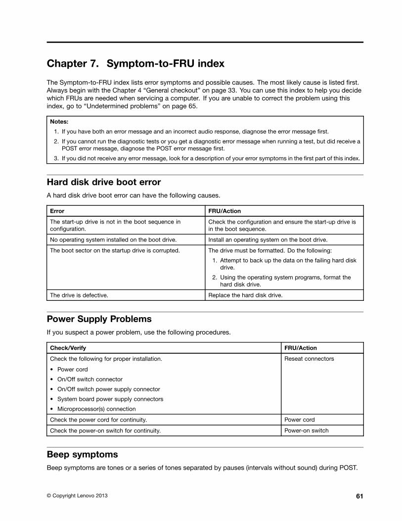
Chapter 7. Symptom-to-FRU index
The Symptom-to-FRU index lists error symptoms and possible causes. The most likely cause is listed rst.Always begin with the Chapter 4 General checkout on page 33. You can use this index to help you decidewhich FRUs are needed when servicing a computer. If you are unable to correct the problem using thisindex, go to Undetermined problems on page 65.
Notes:
1. If you have both an error message and an incorrect audio response, diagnose the error message rst.
2. If you cannot run the diagnostic tests or you get a diagnostic error message when running a test, but did receive aPOST error message, diagnose the POST error message rst.
3. If you did not receive any error message, look for a description of your error symptoms in the rst part of this index.
Hard disk drive boot errorA hard disk drive boot error can have the following causes.
Error FRU/Action
The start-up drive is not in the boot sequence incon guration.
Check the con guration and ensure the start-up drive isin the boot sequence.
No operating system installed on the boot drive. Install an operating system on the boot drive.
The boot sector on the startup drive is corrupted. The drive must be formatted. Do the following:
1. Attempt to back up the data on the failing hard diskdrive.
2. Using the operating system programs, format thehard disk drive.
The drive is defective. Replace the hard disk drive.
Power Supply ProblemsIf you suspect a power problem, use the following procedures.
Check/Verify FRU/Action
Check the following for proper installation.
Power cord
On/Off switch connector
On/Off switch power supply connector
System board power supply connectors
Microprocessor(s) connection
Reseat connectors
Check the power cord for continuity. Power cord
Check the power-on switch for continuity. Power-on switch
Beep symptomsBeep symptoms are tones or a series of tones separated by pauses (intervals without sound) during POST.
Copyright Lenovo 2013 61
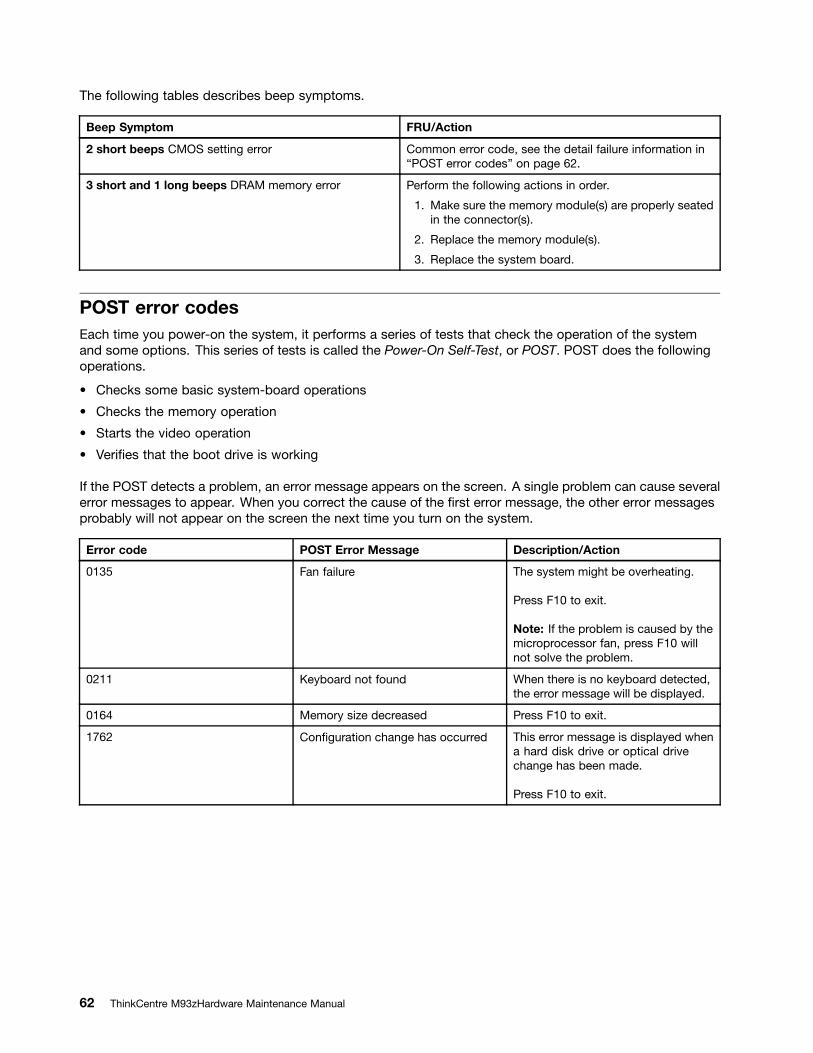
The following tables describes beep symptoms.
Beep Symptom FRU/Action
2 short beeps CMOS setting error Common error code, see the detail failure information inPOST error codes on page 62.
3 short and 1 long beeps DRAM memory error Perform the following actions in order.
1. Make sure the memory module(s) are properly seatedin the connector(s).
2. Replace the memory module(s).
3. Replace the system board.
POST error codesEach time you power-on the system, it performs a series of tests that check the operation of the systemand some options. This series of tests is called the Power-On Self-Test, or POST. POST does the followingoperations.
Checks some basic system-board operations
Checks the memory operation
Starts the video operation
Veri es that the boot drive is working
If the POST detects a problem, an error message appears on the screen. A single problem can cause severalerror messages to appear. When you correct the cause of the rst error message, the other error messagesprobably will not appear on the screen the next time you turn on the system.
Error code POST Error Message Description/Action
0135 Fan failure The system might be overheating.
Press F10 to exit.
Note: If the problem is caused by themicroprocessor fan, press F10 willnot solve the problem.
0211 Keyboard not found When there is no keyboard detected,the error message will be displayed.
0164 Memory size decreased Press F10 to exit.
1762 Con guration change has occurred This error message is displayed whena hard disk drive or optical drivechange has been made.
Press F10 to exit.
62 ThinkCentre M93zHardware Maintenance Manual
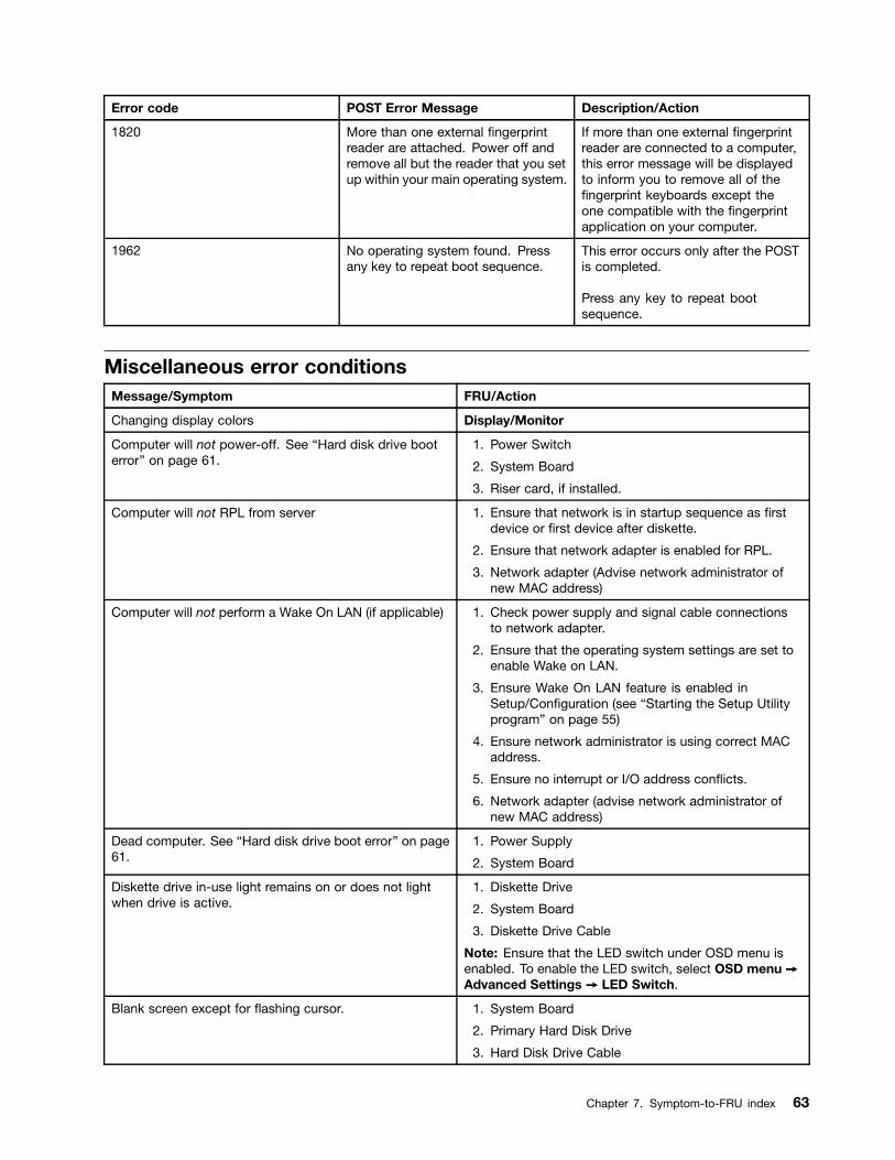
Error code POST Error Message Description/Action
1820 More than one external ngerprintreader are attached. Power off andremove all but the reader that you setup within your main operating system.
If more than one external ngerprintreader are connected to a computer,this error message will be displayedto inform you to remove all of thengerprint keyboards except the
one compatible with the ngerprintapplication on your computer.
1962 No operating system found. Pressany key to repeat boot sequence.
This error occurs only after the POSTis completed.
Press any key to repeat bootsequence.
Miscellaneous error conditionsMessage/Symptom FRU/Action
Changing display colors Display/Monitor
Computer will not power-off. See Hard disk drive booterror on page 61.
1. Power Switch
2. System Board
3. Riser card, if installed.
Computer will not RPL from server 1. Ensure that network is in startup sequence as rstdevice or rst device after diskette.
2. Ensure that network adapter is enabled for RPL.
3. Network adapter (Advise network administrator ofnew MAC address)
Computer will not perform a Wake On LAN (if applicable) 1. Check power supply and signal cable connectionsto network adapter.
2. Ensure that the operating system settings are set toenable Wake on LAN.
3. Ensure Wake On LAN feature is enabled inSetup/Con guration (see Starting the Setup Utilityprogram on page 55)
4. Ensure network administrator is using correct MACaddress.
5. Ensure no interrupt or I/O address con icts.
6. Network adapter (advise network administrator ofnew MAC address)
Dead computer. See Hard disk drive boot error on page61.
1. Power Supply
2. System Board
Diskette drive in-use light remains on or does not lightwhen drive is active.
1. Diskette Drive
2. System Board
3. Diskette Drive Cable
Note: Ensure that the LED switch under OSD menu isenabled. To enable the LED switch, select OSD menu ᇆAdvanced Settings ᇆ LED Switch.
Blank screen except for ashing cursor. 1. System Board
2. Primary Hard Disk Drive
3. Hard Disk Drive Cable
Chapter 7. Symptom-to-FRU index 63
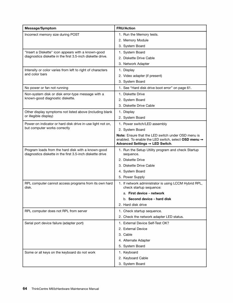
Message/Symptom FRU/Action
Incorrect memory size during POST 1. Run the Memory tests.
2. Memory Module
3. System Board
"Insert a Diskette" icon appears with a known-gooddiagnostics diskette in the rst 3.5-inch diskette drive.
1. System Board
2. Diskette Drive Cable
3. Network Adapter
Intensity or color varies from left to right of charactersand color bars
1. Display
2. Video adapter (if present)
3. System Board
No power or fan not running 1. See Hard disk drive boot error on page 61.
Non-system disk or disk error-type message with aknown-good diagnostic diskette.
1. Diskette Drive
2. System Board
3. Diskette Drive Cable
Other display symptoms not listed above (including blankor illegible display)
1. Display
2. System Board
Power-on indicator or hard disk drive in-use light not on,but computer works correctly
1. Power switch/LED assembly
2. System Board
Note: Ensure that the LED switch under OSD menu isenabled. To enable the LED switch, select OSD menu ᇆAdvanced Settings ᇆ LED Switch.
Program loads from the hard disk with a known-gooddiagnostics diskette in the rst 3.5-inch diskette drive
1. Run the Setup Utility program and check Startupsequence.
2. Diskette Drive
3. Diskette Drive Cable
4. System Board
5. Power Supply
RPL computer cannot access programs from its own harddisk.
1. If network administrator is using LCCM Hybrid RPL,check startup sequence:
a. First device - network
b. Second device - hard disk
2. Hard disk drive
RPL computer does not RPL from server 1. Check startup sequence.
2. Check the network adapter LED status.
Serial port device failure (adapter port) 1. External Device Self-Test OK?
2. External Device
3. Cable
4. Alternate Adapter
5. System Board
Some or all keys on the keyboard do not work 1. Keyboard
2. Keyboard Cable
3. System Board
64 ThinkCentre M93zHardware Maintenance Manual
Undetermined problemsThis section provides instructions on how to nd out the failing devices or adapters.
1. Power-off the computer.
2. Remove or disconnect the following components (if installed) one at a time.
a. Any adapters
b. Diskette drive
c. External Cache
d. External Cache RAM
e. External devices (modem, printer, or mouse)
f. Hard disk drive
g. Internal devices (card reader, Wi-Fi card, ExpressCard, camera, touch panel control board, rearI/O board or cables)
h. Memory modules
3. Power-on the computer to re-test the system.
4. Repeat steps 1 through 3 until you nd the failing device or adapter.
If all devices and adapters have been removed, and the problem continues, replace the system board.
Chapter 7. Symptom-to-FRU index 65

66 ThinkCentre M93zHardware Maintenance Manual
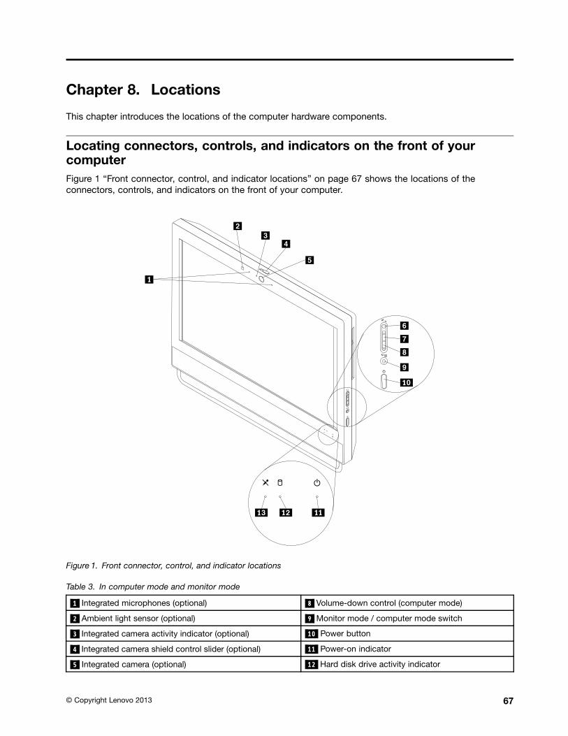
Chapter 8. Locations
This chapter introduces the locations of the computer hardware components.
Locating connectors, controls, and indicators on the front of yourcomputerFigure 1 Front connector, control, and indicator locations on page 67 shows the locations of theconnectors, controls, and indicators on the front of your computer.
Figure 1. Front connector, control, and indicator locations
Table 3. In computer mode and monitor mode
1 Integrated microphones (optional) 8 Volume-down control (computer mode)
2 Ambient light sensor (optional) 9 Monitor mode / computer mode switch
3 Integrated camera activity indicator (optional) 10 Power button
4 Integrated camera shield control slider (optional) 11 Power-on indicator
5 Integrated camera (optional) 12 Hard disk drive activity indicator
Copyright Lenovo 2013 67
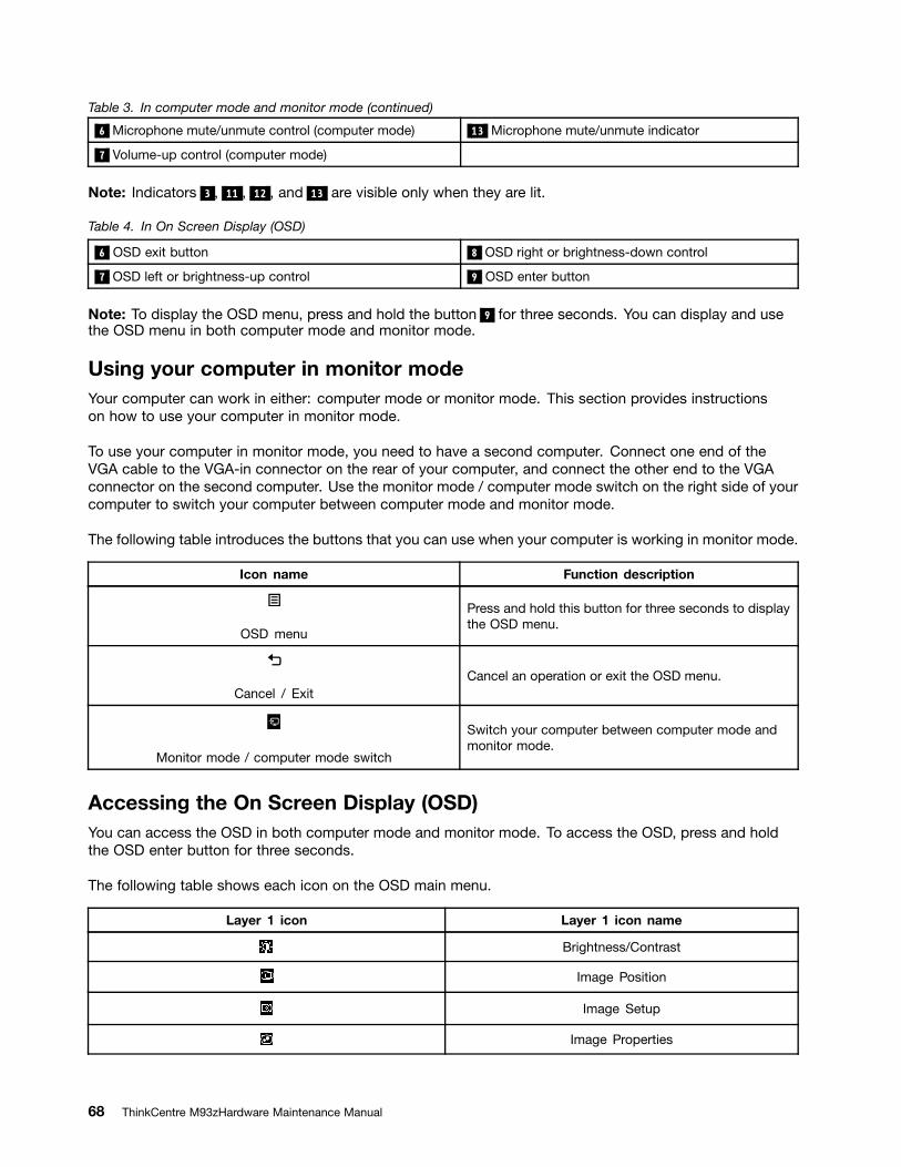
Table 3. In computer mode and monitor mode (continued)
6 Microphone mute/unmute control (computer mode) 13 Microphone mute/unmute indicator
7 Volume-up control (computer mode)
Note: Indicators 3 , 11 , 12 , and 13 are visible only when they are lit.
Table 4. In On Screen Display (OSD)
6 OSD exit button 8 OSD right or brightness-down control
7 OSD left or brightness-up control 9 OSD enter button
Note: To display the OSD menu, press and hold the button 9 for three seconds. You can display and usethe OSD menu in both computer mode and monitor mode.
Using your computer in monitor modeYour computer can work in either: computer mode or monitor mode. This section provides instructionson how to use your computer in monitor mode.
To use your computer in monitor mode, you need to have a second computer. Connect one end of theVGA cable to the VGA-in connector on the rear of your computer, and connect the other end to the VGAconnector on the second computer. Use the monitor mode / computer mode switch on the right side of yourcomputer to switch your computer between computer mode and monitor mode.
The following table introduces the buttons that you can use when your computer is working in monitor mode.
Icon name Function description
OSD menu
Press and hold this button for three seconds to displaythe OSD menu.
Cancel / ExitCancel an operation or exit the OSD menu.
Monitor mode / computer mode switch
Switch your computer between computer mode andmonitor mode.
Accessing the On Screen Display (OSD)You can access the OSD in both computer mode and monitor mode. To access the OSD, press and holdthe OSD enter button for three seconds.
The following table shows each icon on the OSD main menu.
Layer 1 icon Layer 1 icon name
Brightness/Contrast
Image Position
Image Setup
Image Properties
68 ThinkCentre M93zHardware Maintenance Manual
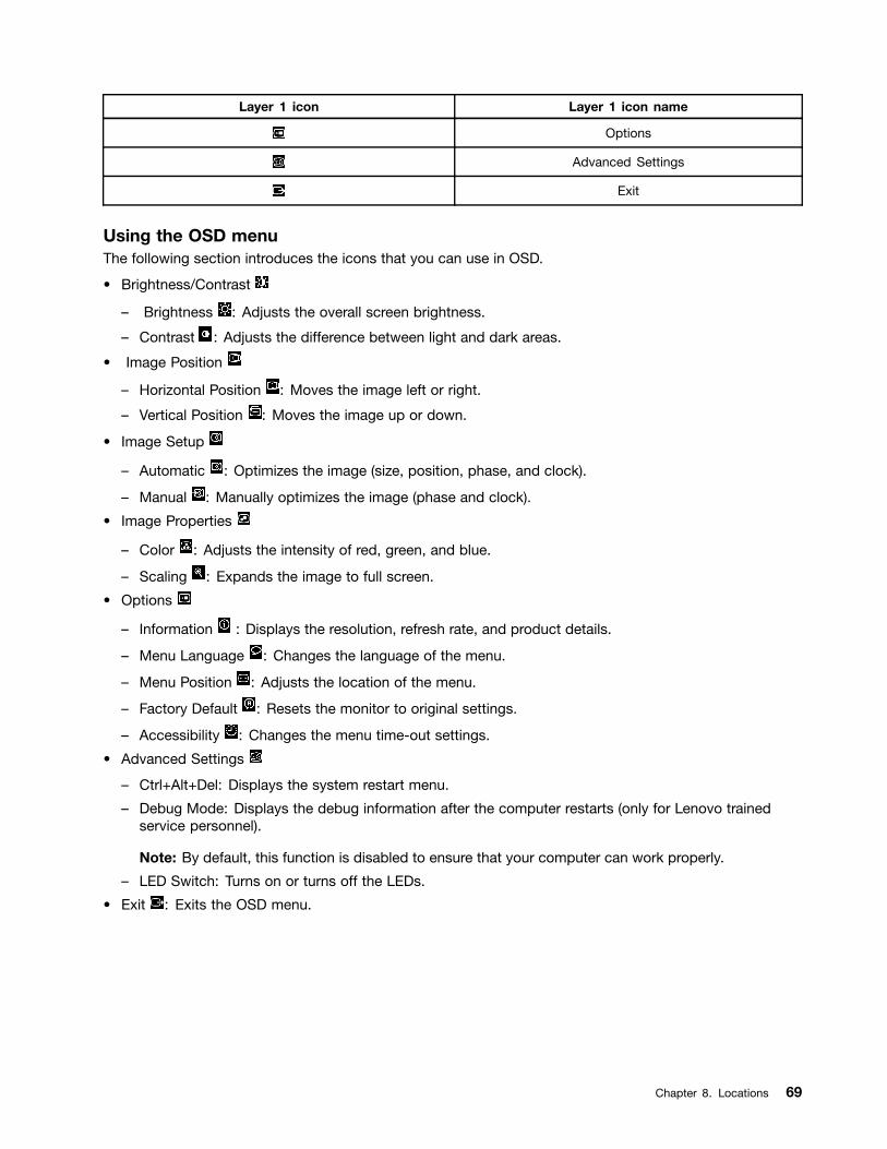
Layer 1 icon Layer 1 icon name
Options
Advanced Settings
Exit
Using the OSD menuThe following section introduces the icons that you can use in OSD.
Brightness/Contrast
Brightness : Adjusts the overall screen brightness.
Contrast : Adjusts the difference between light and dark areas.
Image Position
Horizontal Position : Moves the image left or right.
Vertical Position : Moves the image up or down.
Image Setup
Automatic : Optimizes the image (size, position, phase, and clock).
Manual : Manually optimizes the image (phase and clock).
Image Properties
Color : Adjusts the intensity of red, green, and blue.
Scaling : Expands the image to full screen.
Options
Information : Displays the resolution, refresh rate, and product details.
Menu Language : Changes the language of the menu.
Menu Position : Adjusts the location of the menu.
Factory Default : Resets the monitor to original settings.
Accessibility : Changes the menu time-out settings.
Advanced Settings
Ctrl+Alt+Del: Displays the system restart menu.
Debug Mode: Displays the debug information after the computer restarts (only for Lenovo trainedservice personnel).
Note: By default, this function is disabled to ensure that your computer can work properly.
LED Switch: Turns on or turns off the LEDs.
Exit : Exits the OSD menu.
Chapter 8. Locations 69

Locating connectors on the rear of your computerFigure 2 Rear connector locations on page 70 shows the locations of the connectors on the rear of yourcomputer. Some connectors on the rear of your computer are color-coded to help you determine where toconnect the cables on your computer.
Figure 2. Rear connector locations
1 Optical drive (optional) 9 VGA-in connector
2 PS/2 mouse connector (optional) 10 USB 3.0 connectors (USB ports 3 to 6)
3 PS/2 keyboard connector (optional) 11 ExpressCard slot (optional)
4 Serial connector (optional) 12 Card reader slot (optional)
5 Power cord connector 13 USB 3.0 connector (USB port 2) (supporting USBcharging)
6 Security-lock slot 14 Headset connector (also known as combo audioconnector)
70 ThinkCentre M93zHardware Maintenance Manual
7 Ethernet connector 15 Microphone connector
8 DisplayPort-out connector 16 USB 3.0 connector (USB port 1)
Notes:
The headset connector 14 supports a microphone-integrated headset and does not support aconventional microphone.
By default, the USB 3.0 connector 13 enables you to charge some mobile digital devices andsmartphones when your computer is in sleep mode, in hibernation mode, or turned off.
The card reader slot 12 is for 11-in-1 card readers, supporting the following cards:
Extreme Digital (x-D) Picture Card (type H)
Extreme Digital (x-D) Picture Card (type M)
Memory Stick (MS)
MS PRO
MultiMediaCard (MMC)
MultiMediaCard-mobile (MMC-mobile)
MultiMediaCard-plus (MMC-plus)
Reduced-Size MultiMediaCard (RS-MMC)
Secure Digital (SD) card
Secure Digital eXtended-Capacity (SDXC) card
Secure Digital High-Capacity (SDHC) card
Locating major FRUs and CRUsFigure 3 Locating major FRUs and CRUs for models with the 23-inch display on page 72 shows thelocations of the major FRUs and CRUs in the computer. To remove the computer cover, see Removing thecomputer cover on page 84.
Chapter 8. Locations 71
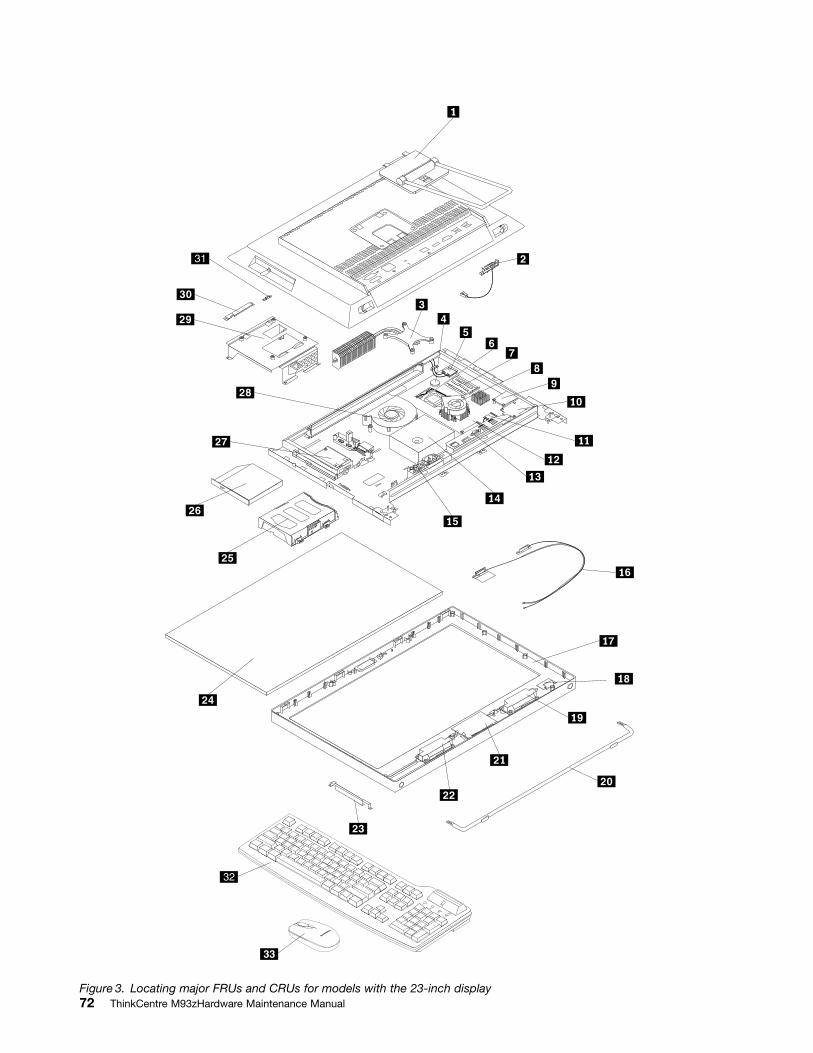
3
4
5
6
33
31
32
Figure 3. Locating major FRUs and CRUs for models with the 23-inch display72 ThinkCentre M93zHardware Maintenance Manual
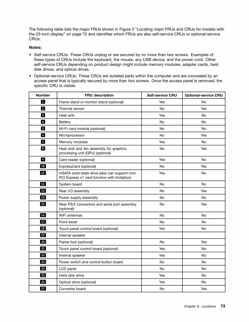
The following table lists the major FRUs shown in Figure 3 Locating major FRUs and CRUs for models withthe 23-inch display on page 72 and identi es which FRUs are also self-service CRUs or optional-serviceCRUs.
Notes:
Self-service CRUs: These CRUs unplug or are secured by no more than two screws. Examples ofthese types of CRUs include the keyboard, the mouse, any USB device, and the power cord. Otherself-service CRUs depending on product design might include memory modules, adapter cards, harddisk drives, and optical drives.
Optional-service CRUs: These CRUs are isolated parts within the computer and are concealed by anaccess panel that is typically secured by more than two screws. Once the access panel is removed, thespeci c CRU is visible.
Number FRU description Self-service CRU Optional-service CRU
1 Frame stand or monitor stand (optional) Yes No
2 Thermal sensor No Yes
3 Heat sink Yes No
4 Battery No No
5 Wi-Fi card module (optional) No No
6 Microprocessor No Yes
7 Memory modules Yes No
8 Heat sink and fan assembly for graphicsprocessing unit (GPU) (optional)
No Yes
9 Card reader (optional) Yes No
10 ExpressCard (optional) No Yes
11 mSATA solid-state drive (also can support miniPCI Express x1 card function with limitation)
Yes No
12 System board No No
13 Rear I/O assembly No Yes
14 Power supply assembly No No
15 Rear PS/2 connectors and serial port assembly(optional)
No Yes
16 WiFi antennas No No
17 Front bezel No No
18 Touch panel control board (optional) Yes No
19 Internal speaker
20 Frame foot (optional) No Yes
21 Touch panel control board (optional) Yes No
22 Internal speaker Yes No
23 Power switch and control button board No No
24 LCD panel No No
25 Hard disk drive Yes No
26 Optical drive (optional) Yes No
27 Converter board No Yes
Chapter 8. Locations 73
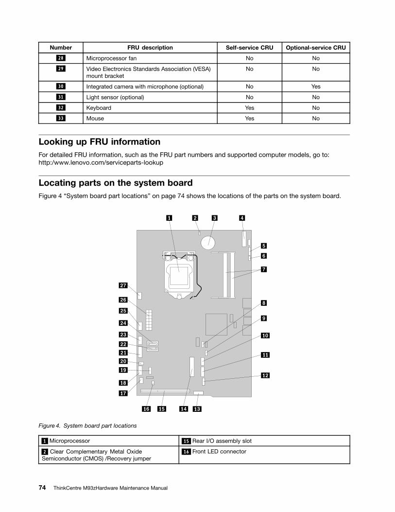
Number FRU description Self-service CRU Optional-service CRU
28 Microprocessor fan No No
29 Video Electronics Standards Association (VESA)mount bracket
No No
30 Integrated camera with microphone (optional) No Yes
31 Light sensor (optional) No No
32 Keyboard Yes No
33 Mouse Yes No
Looking up FRU informationFor detailed FRU information, such as the FRU part numbers and supported computer models, go to:http:/www.lenovo.com/serviceparts-lookup
Locating parts on the system boardFigure 4 System board part locations on page 74 shows the locations of the parts on the system board.
Figure 4. System board part locations
1 Microprocessor 15 Rear I/O assembly slot
2 Clear Complementary Metal OxideSemiconductor (CMOS) /Recovery jumper
16 Front LED connector
74 ThinkCentre M93zHardware Maintenance Manual
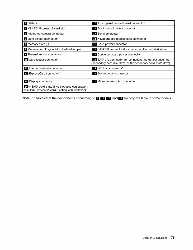
3 Battery 17 Touch panel control board connector*
4 Mini PCI Express x1 card slot 18 Front control panel connector
5 Integrated camera connector 19 Serial connector
6 Light sensor connector* 20 Keyboard and mouse cable connector
7 Memory slots (2) 21 SATA power connector
8 Management Engine (ME) disabled jumper 22 SATA 3.0 connector (for connecting the hard disk drive)
9 Thermal sensor connector 23 Converter board power connector
10 Card reader connector 24 SATA 3.0 connector (for connecting the optical drive, thesecondary hard disk drive, or the secondary solid-state drive)
11 Internal speaker connector 25 GPU fan connector*
12 ExpressCard connector* 26 14-pin power connector
13 Display connector 27 Microprocessor fan connector
14 mSATA solid-state drive slot (also can supportmini PCI Express x1 card function with limitation)
Note: * denotes that the components connecting to 6 , 12 , 17 , and 25 are only available in some models.
Chapter 8. Locations 75
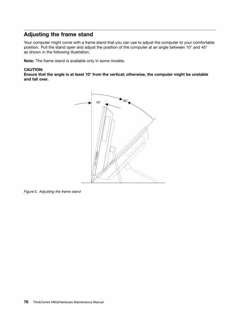
Adjusting the frame standYour computer might come with a frame stand that you can use to adjust the computer to your comfortableposition. Pull the stand open and adjust the position of the computer at an angle between 10 and 45as shown in the following illustration.
Note: The frame stand is available only in some models.
CAUTION:Ensure that the angle is at least 10 from the vertical; otherwise, the computer might be unstableand fall over.
Figure 5. Adjusting the frame stand
76 ThinkCentre M93zHardware Maintenance Manual
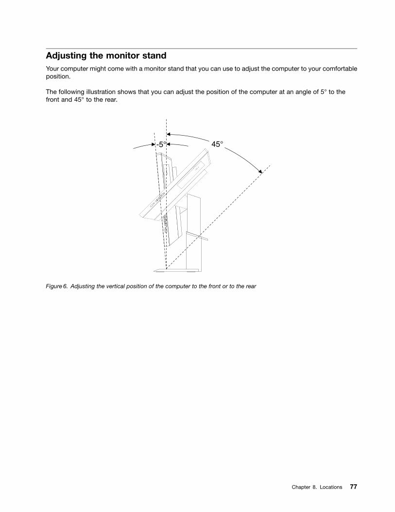
Adjusting the monitor standYour computer might come with a monitor stand that you can use to adjust the computer to your comfortableposition.
The following illustration shows that you can adjust the position of the computer at an angle of 5 to thefront and 45 to the rear.
Figure 6. Adjusting the vertical position of the computer to the front or to the rear
Chapter 8. Locations 77
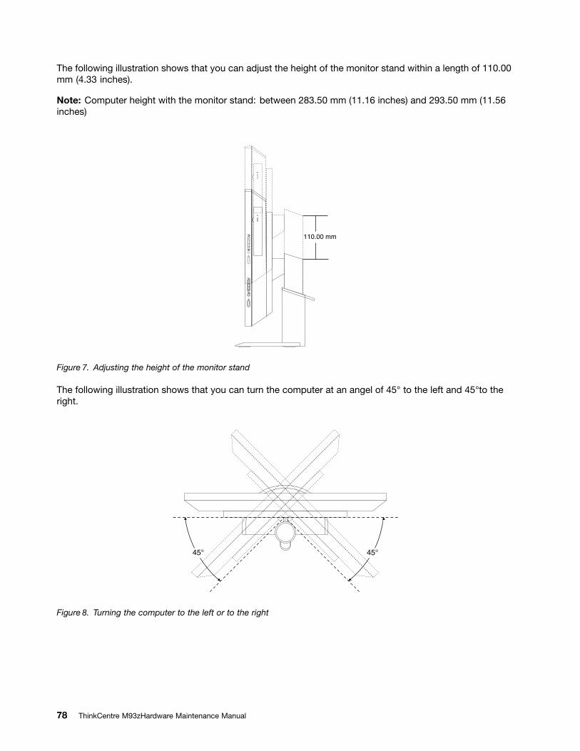
The following illustration shows that you can adjust the height of the monitor stand within a length of 110.00mm (4.33 inches).
Note: Computer height with the monitor stand: between 283.50 mm (11.16 inches) and 293.50 mm (11.56inches)
Figure 7. Adjusting the height of the monitor stand
The following illustration shows that you can turn the computer at an angel of 45 to the left and 45 to theright.
Figure 8. Turning the computer to the left or to the right
78 ThinkCentre M93zHardware Maintenance Manual
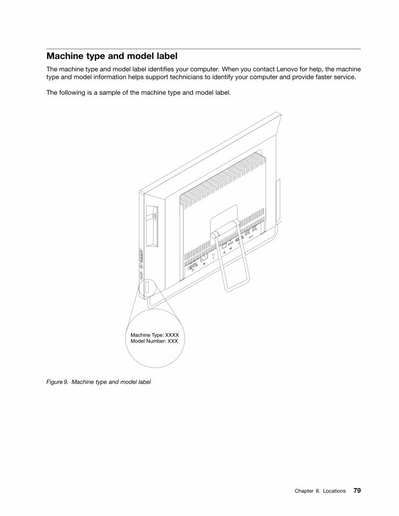
Machine type and model labelThe machine type and model label identi es your computer. When you contact Lenovo for help, the machinetype and model information helps support technicians to identify your computer and provide faster service.
The following is a sample of the machine type and model label.
Figure 9. Machine type and model label
Chapter 8. Locations 79

80 ThinkCentre M93zHardware Maintenance Manual
Chapter 9. Replacing FRUs
This chapter provides instructions about removing or replacing major FRUs. Not all FRUs are documented.
Important
Before you replace any FRU, read Chapter 2 Safety information on page 3. These precautions andguidelines will help you work safely.
FRU replacements are to be done by trained service technicians only.
Handling static-sensitive devicesDo not open the static-protective package containing the new part until the defective part has been removedfrom the computer and you are ready to install the new part. Static electricity, although harmless to you, canseriously damage computer components and parts.
When you handle parts and other computer components, take these precautions to avoid static-electricitydamage:
Limit your movement. Movement can cause static electricity to build up around you.
Always handle parts and other computer components carefully. Handle PCI cards, memory modules,system boards, and microprocessors by the edges. Never touch any exposed circuitry.
Prevent others from touching the parts and other computer components.
Before you replace a new part, touch the static-protective package containing the part to a metalexpansion-slot cover or other unpainted metal surface on the computer for at least two seconds. Thisreduces static electricity from the package and your body.
When possible, remove the new part from the static-protective packaging, and install it directly in thecomputer without setting the part down. When this is not possible, place the static-protective packagethat the part came in on a smooth, level surface and place the part on it.
Do not place the part on the computer cover or other metal surface.
Installing or replacing hardwareThis section provides instructions on how to install or replace hardware for your computer. You can expandthe capabilities of your computer and maintain your computer by installing or replacing hardware.
Attention:Do not open your computer or attempt any repair before reading and understanding Important Safety Informationon page 1.
Notes:
1. Use only computer parts provided by Lenovo.
2. When installing or replacing an option, use the appropriate instructions in this section along with theinstructions that come with the option.
Installing external optionsYou can connect external options to your computer, such as external speakers, a printer, or a scanner. Forsome external options, you must install additional software in addition to making the physical connection.When installing an external option, see Locating connectors, controls, and indicators on the front of your
Copyright Lenovo 2013 81
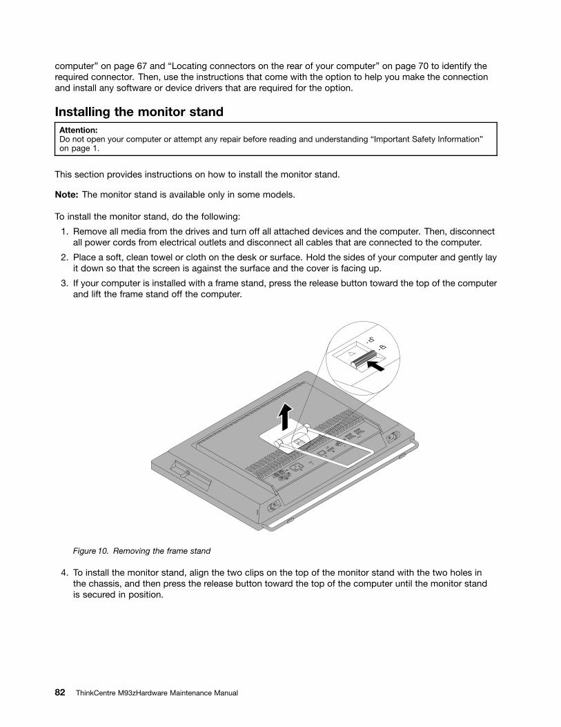
computer on page 67 and Locating connectors on the rear of your computer on page 70 to identify therequired connector. Then, use the instructions that come with the option to help you make the connectionand install any software or device drivers that are required for the option.
Installing the monitor standAttention:Do not open your computer or attempt any repair before reading and understanding Important Safety Informationon page 1.
This section provides instructions on how to install the monitor stand.
Note: The monitor stand is available only in some models.
To install the monitor stand, do the following:
1. Remove all media from the drives and turn off all attached devices and the computer. Then, disconnectall power cords from electrical outlets and disconnect all cables that are connected to the computer.
2. Place a soft, clean towel or cloth on the desk or surface. Hold the sides of your computer and gently layit down so that the screen is against the surface and the cover is facing up.
3. If your computer is installed with a frame stand, press the release button toward the top of the computerand lift the frame stand off the computer.
Figure 10. Removing the frame stand
4. To install the monitor stand, align the two clips on the top of the monitor stand with the two holes inthe chassis, and then press the release button toward the top of the computer until the monitor standis secured in position.
82 ThinkCentre M93zHardware Maintenance Manual
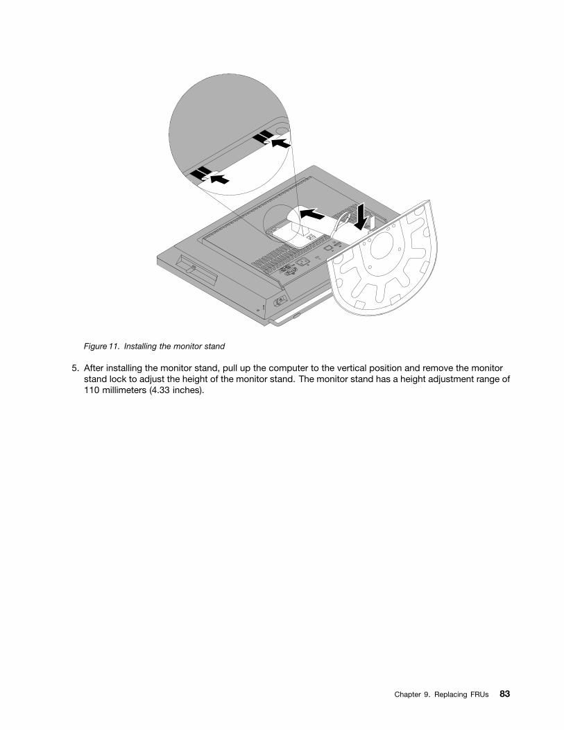
Figure 11. Installing the monitor stand
5. After installing the monitor stand, pull up the computer to the vertical position and remove the monitorstand lock to adjust the height of the monitor stand. The monitor stand has a height adjustment range of110 millimeters (4.33 inches).
Chapter 9. Replacing FRUs 83
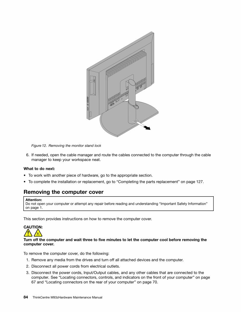
Figure 12. Removing the monitor stand lock
6. If needed, open the cable manager and route the cables connected to the computer through the cablemanager to keep your workspace neat.
What to do next:
To work with another piece of hardware, go to the appropriate section.
To complete the installation or replacement, go to Completing the parts replacement on page 127.
Removing the computer coverAttention:Do not open your computer or attempt any repair before reading and understanding Important Safety Informationon page 1.
This section provides instructions on how to remove the computer cover.
CAUTION:
Turn off the computer and wait three to ve minutes to let the computer cool before removing thecomputer cover.
To remove the computer cover, do the following:
1. Remove any media from the drives and turn off all attached devices and the computer.
2. Disconnect all power cords from electrical outlets.
3. Disconnect the power cords, Input/Output cables, and any other cables that are connected to thecomputer. See Locating connectors, controls, and indicators on the front of your computer on page67 and Locating connectors on the rear of your computer on page 70.
84 ThinkCentre M93zHardware Maintenance Manual
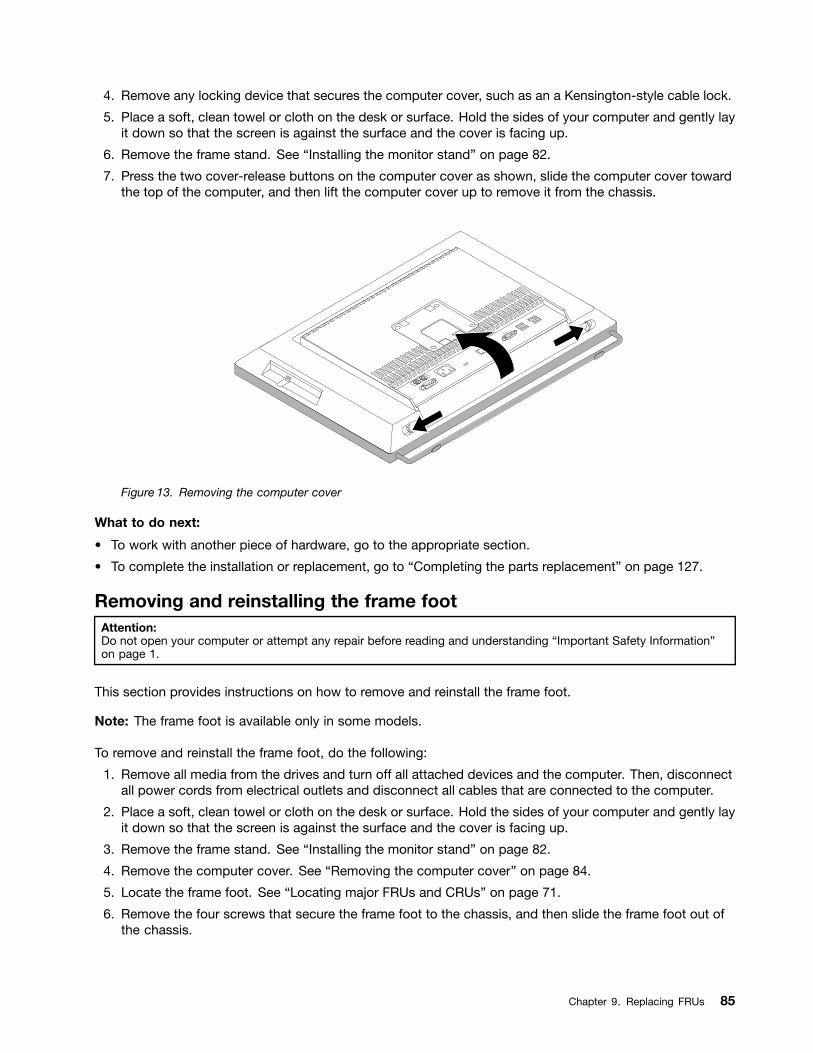
4. Remove any locking device that secures the computer cover, such as an a Kensington-style cable lock.
5. Place a soft, clean towel or cloth on the desk or surface. Hold the sides of your computer and gently layit down so that the screen is against the surface and the cover is facing up.
6. Remove the frame stand. See Installing the monitor stand on page 82.
7. Press the two cover-release buttons on the computer cover as shown, slide the computer cover towardthe top of the computer, and then lift the computer cover up to remove it from the chassis.
Figure 13. Removing the computer cover
What to do next:
To work with another piece of hardware, go to the appropriate section.
To complete the installation or replacement, go to Completing the parts replacement on page 127.
Removing and reinstalling the frame footAttention:Do not open your computer or attempt any repair before reading and understanding Important Safety Informationon page 1.
This section provides instructions on how to remove and reinstall the frame foot.
Note: The frame foot is available only in some models.
To remove and reinstall the frame foot, do the following:
1. Remove all media from the drives and turn off all attached devices and the computer. Then, disconnectall power cords from electrical outlets and disconnect all cables that are connected to the computer.
2. Place a soft, clean towel or cloth on the desk or surface. Hold the sides of your computer and gently layit down so that the screen is against the surface and the cover is facing up.
3. Remove the frame stand. See Installing the monitor stand on page 82.
4. Remove the computer cover. See Removing the computer cover on page 84.
5. Locate the frame foot. See Locating major FRUs and CRUs on page 71.
6. Remove the four screws that secure the frame foot to the chassis, and then slide the frame foot out ofthe chassis.
Chapter 9. Replacing FRUs 85
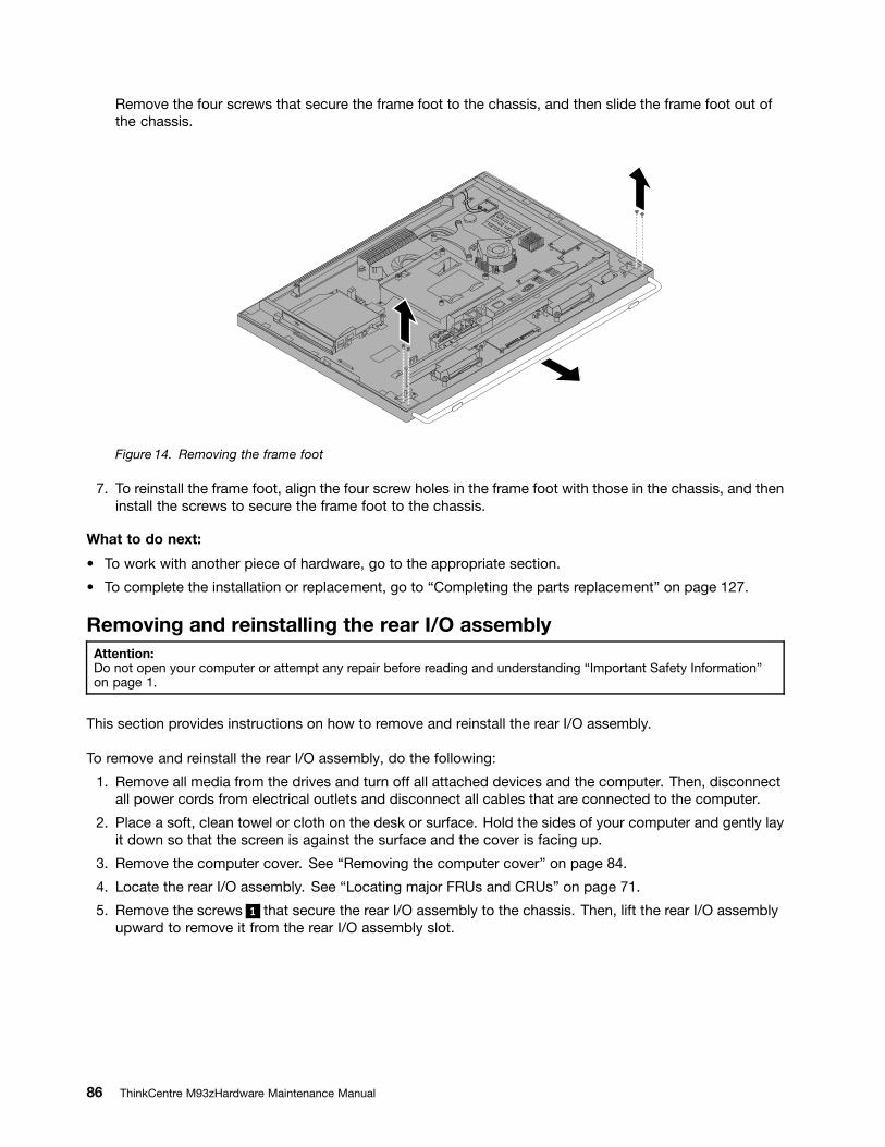
Remove the four screws that secure the frame foot to the chassis, and then slide the frame foot out ofthe chassis.
Figure 14. Removing the frame foot
7. To reinstall the frame foot, align the four screw holes in the frame foot with those in the chassis, and theninstall the screws to secure the frame foot to the chassis.
What to do next:
To work with another piece of hardware, go to the appropriate section.
To complete the installation or replacement, go to Completing the parts replacement on page 127.
Removing and reinstalling the rear I/O assemblyAttention:Do not open your computer or attempt any repair before reading and understanding Important Safety Informationon page 1.
This section provides instructions on how to remove and reinstall the rear I/O assembly.
To remove and reinstall the rear I/O assembly, do the following:
1. Remove all media from the drives and turn off all attached devices and the computer. Then, disconnectall power cords from electrical outlets and disconnect all cables that are connected to the computer.
2. Place a soft, clean towel or cloth on the desk or surface. Hold the sides of your computer and gently layit down so that the screen is against the surface and the cover is facing up.
3. Remove the computer cover. See Removing the computer cover on page 84.
4. Locate the rear I/O assembly. See Locating major FRUs and CRUs on page 71.
5. Remove the screws 1 that secure the rear I/O assembly to the chassis. Then, lift the rear I/O assemblyupward to remove it from the rear I/O assembly slot.
86 ThinkCentre M93zHardware Maintenance Manual
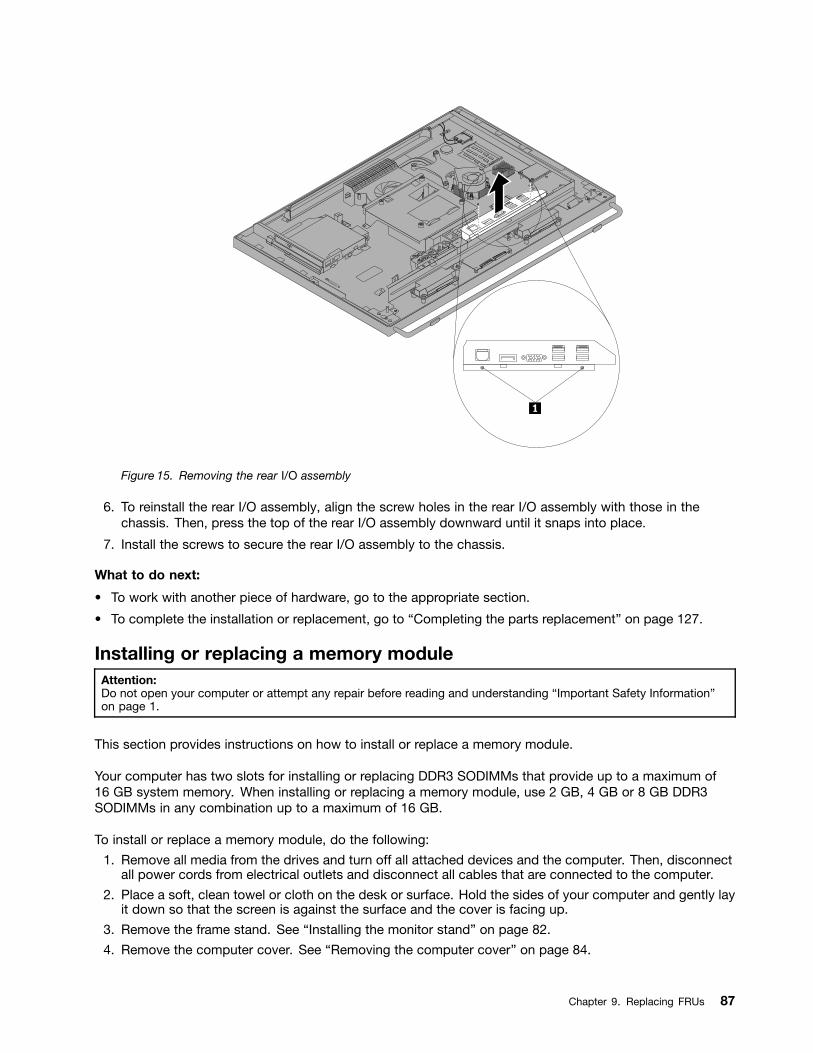
Figure 15. Removing the rear I/O assembly
6. To reinstall the rear I/O assembly, align the screw holes in the rear I/O assembly with those in thechassis. Then, press the top of the rear I/O assembly downward until it snaps into place.
7. Install the screws to secure the rear I/O assembly to the chassis.
What to do next:
To work with another piece of hardware, go to the appropriate section.
To complete the installation or replacement, go to Completing the parts replacement on page 127.
Installing or replacing a memory moduleAttention:Do not open your computer or attempt any repair before reading and understanding Important Safety Informationon page 1.
This section provides instructions on how to install or replace a memory module.
Your computer has two slots for installing or replacing DDR3 SODIMMs that provide up to a maximum of16 GB system memory. When installing or replacing a memory module, use 2 GB, 4 GB or 8 GB DDR3SODIMMs in any combination up to a maximum of 16 GB.
To install or replace a memory module, do the following:
1. Remove all media from the drives and turn off all attached devices and the computer. Then, disconnectall power cords from electrical outlets and disconnect all cables that are connected to the computer.
2. Place a soft, clean towel or cloth on the desk or surface. Hold the sides of your computer and gently layit down so that the screen is against the surface and the cover is facing up.
3. Remove the frame stand. See Installing the monitor stand on page 82.
4. Remove the computer cover. See Removing the computer cover on page 84.
Chapter 9. Replacing FRUs 87
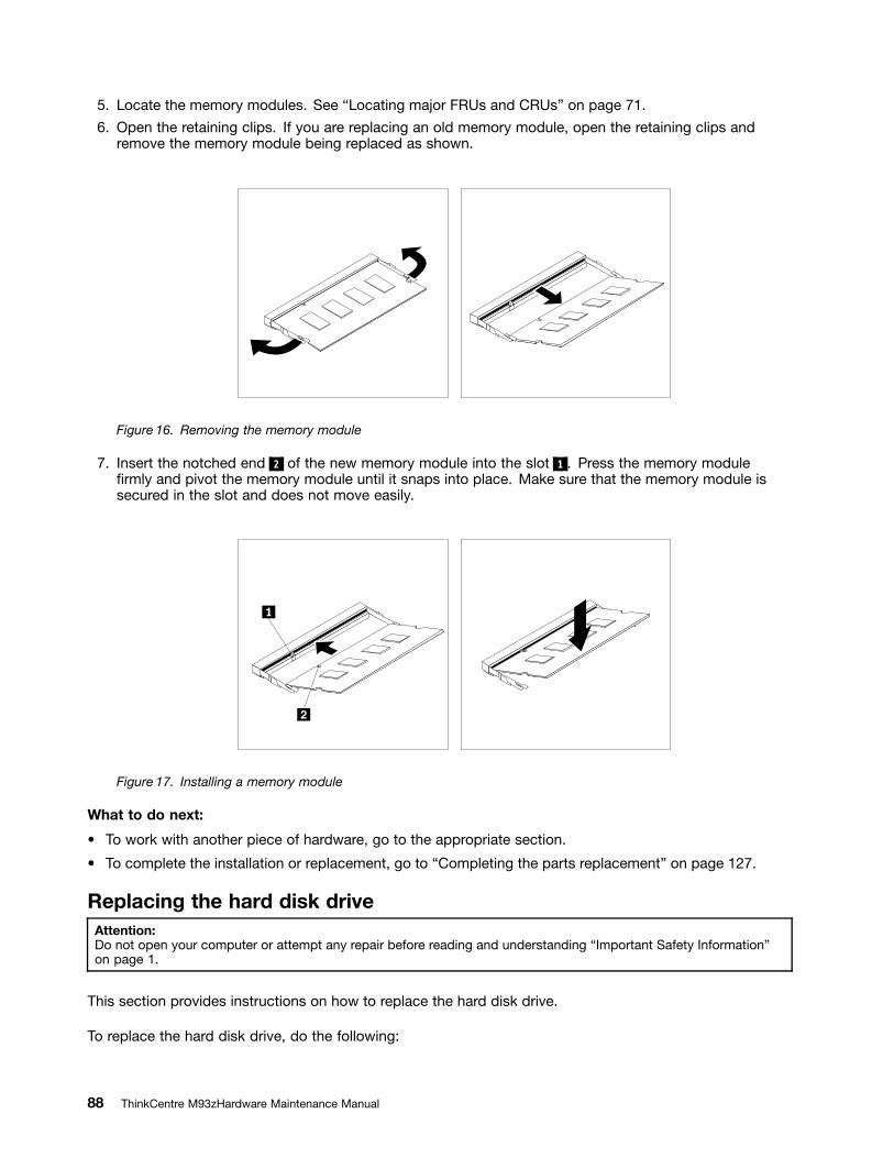
5. Locate the memory modules. See Locating major FRUs and CRUs on page 71.
6. Open the retaining clips. If you are replacing an old memory module, open the retaining clips andremove the memory module being replaced as shown.
Figure 16. Removing the memory module
7. Insert the notched end 2 of the new memory module into the slot 1 . Press the memory modulermly and pivot the memory module until it snaps into place. Make sure that the memory module is
secured in the slot and does not move easily.
Figure 17. Installing a memory module
What to do next:
To work with another piece of hardware, go to the appropriate section.
To complete the installation or replacement, go to Completing the parts replacement on page 127.
Replacing the hard disk driveAttention:Do not open your computer or attempt any repair before reading and understanding Important Safety Informationon page 1.
This section provides instructions on how to replace the hard disk drive.
To replace the hard disk drive, do the following:
88 ThinkCentre M93zHardware Maintenance Manual
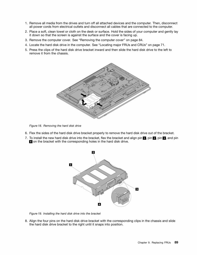
1. Remove all media from the drives and turn off all attached devices and the computer. Then, disconnectall power cords from electrical outlets and disconnect all cables that are connected to the computer.
2. Place a soft, clean towel or cloth on the desk or surface. Hold the sides of your computer and gently layit down so that the screen is against the surface and the cover is facing up.
3. Remove the computer cover. See Removing the computer cover on page 84.
4. Locate the hard disk drive in the computer. See Locating major FRUs and CRUs on page 71.
5. Press the clips of the hard disk drive bracket inward and then slide the hard disk drive to the left toremove it from the chassis.
Figure 18. Removing the hard disk drive
6. Flex the sides of the hard disk drive bracket properly to remove the hard disk drive out of the bracket.
7. To install the new hard disk drive into the bracket, ex the bracket and align pin 1 , pin 2 , pin 3 , and pin4 on the bracket with the corresponding holes in the hard disk drive.
Figure 19. Installing the hard disk drive into the bracket
8. Align the four pins on the hard disk drive bracket with the corresponding clips in the chassis and slidethe hard disk drive bracket to the right until it snaps into position.
Chapter 9. Replacing FRUs 89
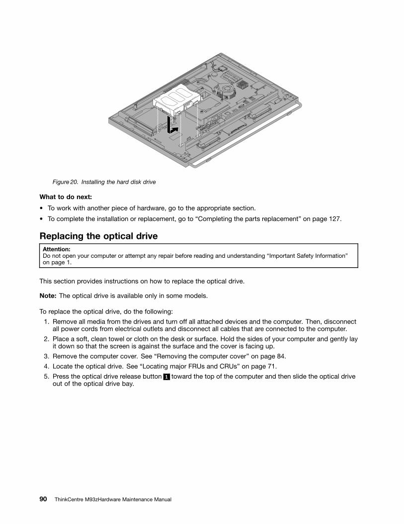
Figure 20. Installing the hard disk drive
What to do next:
To work with another piece of hardware, go to the appropriate section.
To complete the installation or replacement, go to Completing the parts replacement on page 127.
Replacing the optical driveAttention:Do not open your computer or attempt any repair before reading and understanding Important Safety Informationon page 1.
This section provides instructions on how to replace the optical drive.
Note: The optical drive is available only in some models.
To replace the optical drive, do the following:
1. Remove all media from the drives and turn off all attached devices and the computer. Then, disconnectall power cords from electrical outlets and disconnect all cables that are connected to the computer.
2. Place a soft, clean towel or cloth on the desk or surface. Hold the sides of your computer and gently layit down so that the screen is against the surface and the cover is facing up.
3. Remove the computer cover. See Removing the computer cover on page 84.
4. Locate the optical drive. See Locating major FRUs and CRUs on page 71.
5. Press the optical drive release button 1 toward the top of the computer and then slide the optical driveout of the optical drive bay.
90 ThinkCentre M93zHardware Maintenance Manual
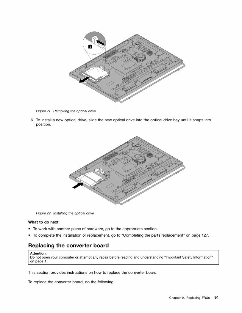
Figure 21. Removing the optical drive
6. To install a new optical drive, slide the new optical drive into the optical drive bay until it snaps intoposition.
Figure 22. Installing the optical drive
What to do next:
To work with another piece of hardware, go to the appropriate section.
To complete the installation or replacement, go to Completing the parts replacement on page 127.
Replacing the converter boardAttention:Do not open your computer or attempt any repair before reading and understanding Important Safety Informationon page 1.
This section provides instructions on how to replace the converter board.
To replace the converter board, do the following:
Chapter 9. Replacing FRUs 91
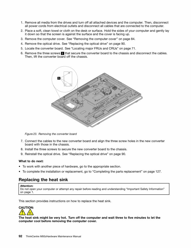
1. Remove all media from the drives and turn off all attached devices and the computer. Then, disconnectall power cords from electrical outlets and disconnect all cables that are connected to the computer.
2. Place a soft, clean towel or cloth on the desk or surface. Hold the sides of your computer and gently layit down so that the screen is against the surface and the cover is facing up.
3. Remove the computer cover. See Removing the computer cover on page 84.
4. Remove the optical drive. See Replacing the optical drive on page 90.
5. Locate the converter board. See Locating major FRUs and CRUs on page 71.
6. Remove the three screws 1 that secure the converter board to the chassis and disconnect the cables.Then, lift the converter board off the chassis.
Figure 23. Removing the converter board
7. Connect the cables to the new converter board and align the three screw holes in the new converterboard with those in the chassis.
8. Install the three screws to secure the new converter board to the chassis.
9. Reinstall the optical drive. See Replacing the optical drive on page 90.
What to do next:
To work with another piece of hardware, go to the appropriate section.
To complete the installation or replacement, go to Completing the parts replacement on page 127.
Replacing the heat sinkAttention:Do not open your computer or attempt any repair before reading and understanding Important Safety Informationon page 1.
This section provides instructions on how to replace the heat sink.
CAUTION:
The heat sink might be very hot. Turn off the computer and wait three to ve minutes to let thecomputer cool before removing the computer cover.
92 ThinkCentre M93zHardware Maintenance Manual
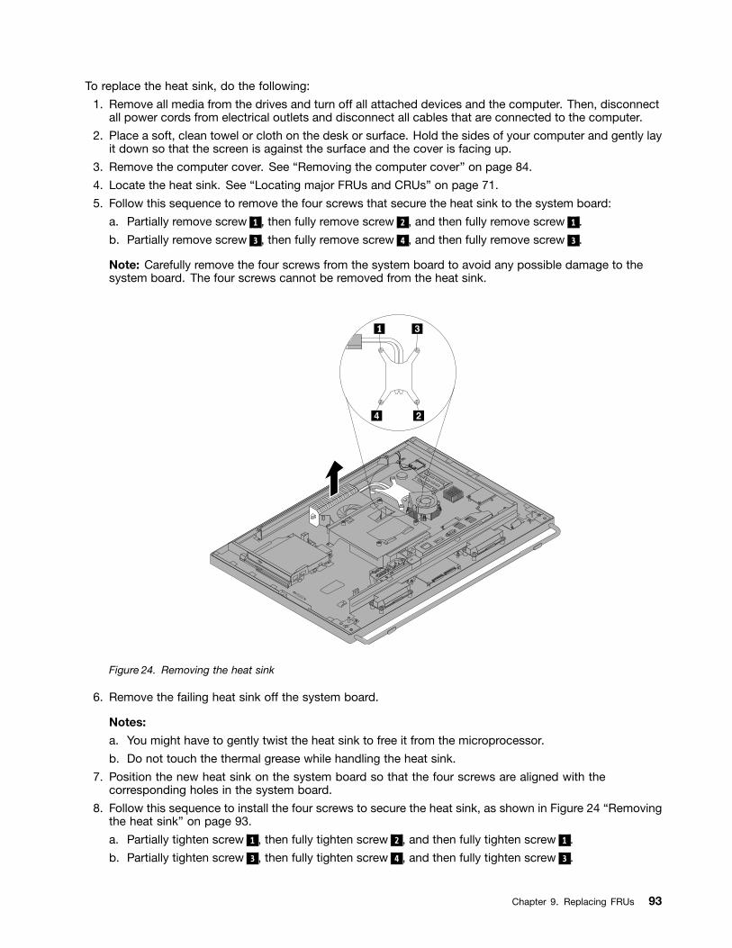
To replace the heat sink, do the following:
1. Remove all media from the drives and turn off all attached devices and the computer. Then, disconnectall power cords from electrical outlets and disconnect all cables that are connected to the computer.
2. Place a soft, clean towel or cloth on the desk or surface. Hold the sides of your computer and gently layit down so that the screen is against the surface and the cover is facing up.
3. Remove the computer cover. See Removing the computer cover on page 84.
4. Locate the heat sink. See Locating major FRUs and CRUs on page 71.
5. Follow this sequence to remove the four screws that secure the heat sink to the system board:
a. Partially remove screw 1 , then fully remove screw 2 , and then fully remove screw 1 .
b. Partially remove screw 3 , then fully remove screw 4 , and then fully remove screw 3 .
Note: Carefully remove the four screws from the system board to avoid any possible damage to thesystem board. The four screws cannot be removed from the heat sink.
Figure 24. Removing the heat sink
6. Remove the failing heat sink off the system board.
Notes:
a. You might have to gently twist the heat sink to free it from the microprocessor.
b. Do not touch the thermal grease while handling the heat sink.
7. Position the new heat sink on the system board so that the four screws are aligned with thecorresponding holes in the system board.
8. Follow this sequence to install the four screws to secure the heat sink, as shown in Figure 24 Removingthe heat sink on page 93.
a. Partially tighten screw 1 , then fully tighten screw 2 , and then fully tighten screw 1 .
b. Partially tighten screw 3 , then fully tighten screw 4 , and then fully tighten screw 3 .
Chapter 9. Replacing FRUs 93
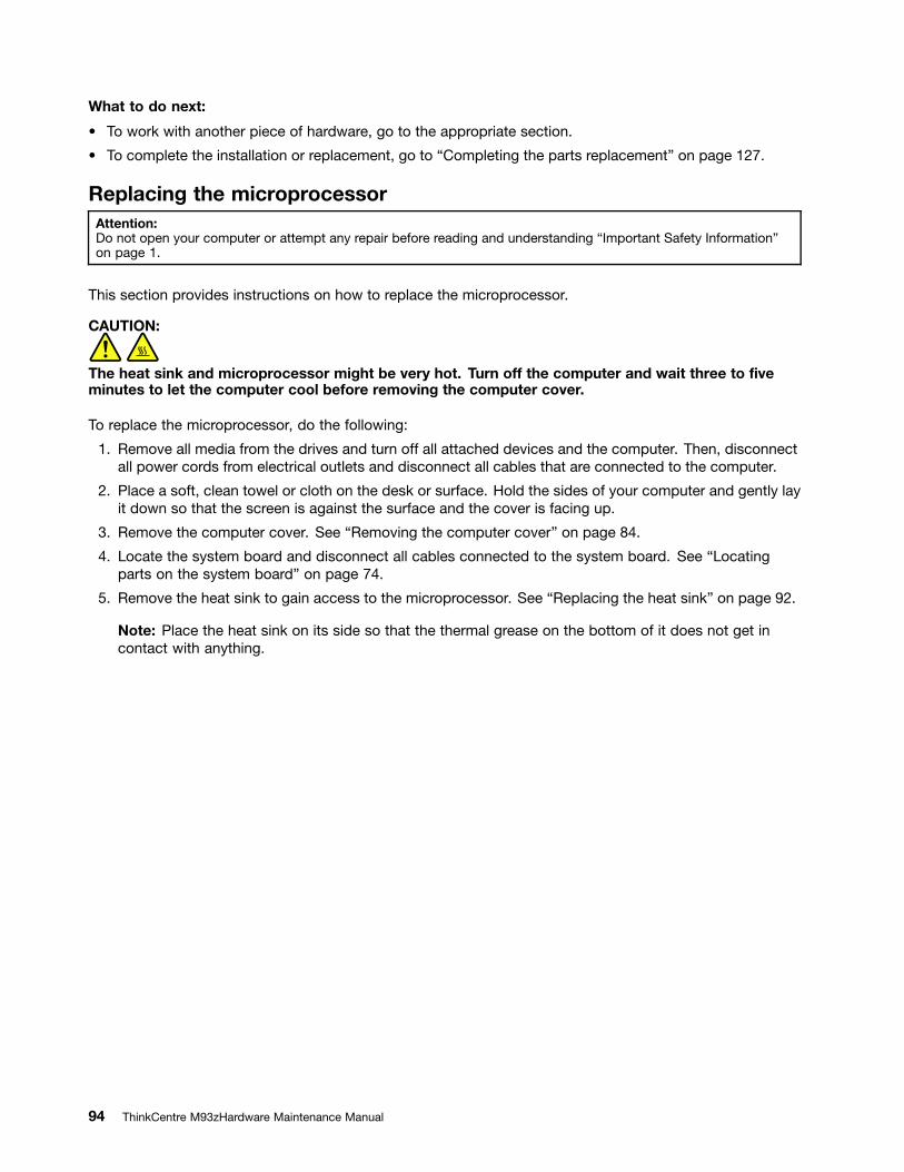
What to do next:
To work with another piece of hardware, go to the appropriate section.
To complete the installation or replacement, go to Completing the parts replacement on page 127.
Replacing the microprocessorAttention:Do not open your computer or attempt any repair before reading and understanding Important Safety Informationon page 1.
This section provides instructions on how to replace the microprocessor.
CAUTION:
The heat sink and microprocessor might be very hot. Turn off the computer and wait three to veminutes to let the computer cool before removing the computer cover.
To replace the microprocessor, do the following:
1. Remove all media from the drives and turn off all attached devices and the computer. Then, disconnectall power cords from electrical outlets and disconnect all cables that are connected to the computer.
2. Place a soft, clean towel or cloth on the desk or surface. Hold the sides of your computer and gently layit down so that the screen is against the surface and the cover is facing up.
3. Remove the computer cover. See Removing the computer cover on page 84.
4. Locate the system board and disconnect all cables connected to the system board. See Locatingparts on the system board on page 74.
5. Remove the heat sink to gain access to the microprocessor. See Replacing the heat sink on page 92.
Note: Place the heat sink on its side so that the thermal grease on the bottom of it does not get incontact with anything.
94 ThinkCentre M93zHardware Maintenance Manual
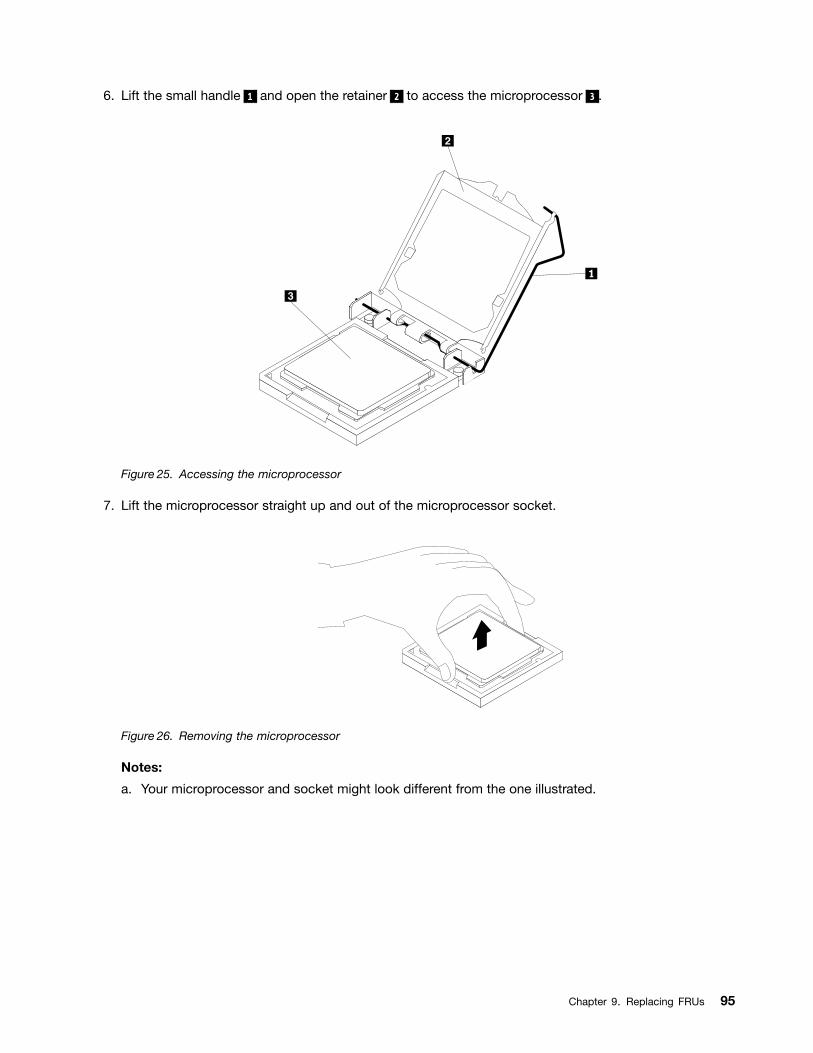
6. Lift the small handle 1 and open the retainer 2 to access the microprocessor 3 .
Figure 25. Accessing the microprocessor
7. Lift the microprocessor straight up and out of the microprocessor socket.
Figure 26. Removing the microprocessor
Notes:
a. Your microprocessor and socket might look different from the one illustrated.
Chapter 9. Replacing FRUs 95
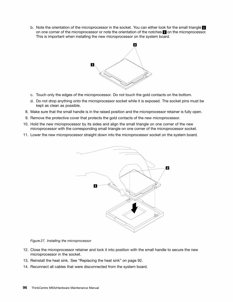
b. Note the orientation of the microprocessor in the socket. You can either look for the small triangle 1
on one corner of the microprocessor or note the orientation of the notches 2 on the microprocessor.This is important when installing the new microprocessor on the system board.
c. Touch only the edges of the microprocessor. Do not touch the gold contacts on the bottom.
d. Do not drop anything onto the microprocessor socket while it is exposed. The socket pins must bekept as clean as possible.
8. Make sure that the small handle is in the raised position and the microprocessor retainer is fully open.
9. Remove the protective cover that protects the gold contacts of the new microprocessor.
10. Hold the new microprocessor by its sides and align the small triangle on one corner of the newmicroprocessor with the corresponding small triangle on one corner of the microprocessor socket.
11. Lower the new microprocessor straight down into the microprocessor socket on the system board.
Figure 27. Installing the microprocessor
12. Close the microprocessor retainer and lock it into position with the small handle to secure the newmicroprocessor in the socket.
13. Reinstall the heat sink. See Replacing the heat sink on page 92.
14. Reconnect all cables that were disconnected from the system board.
96 ThinkCentre M93zHardware Maintenance Manual
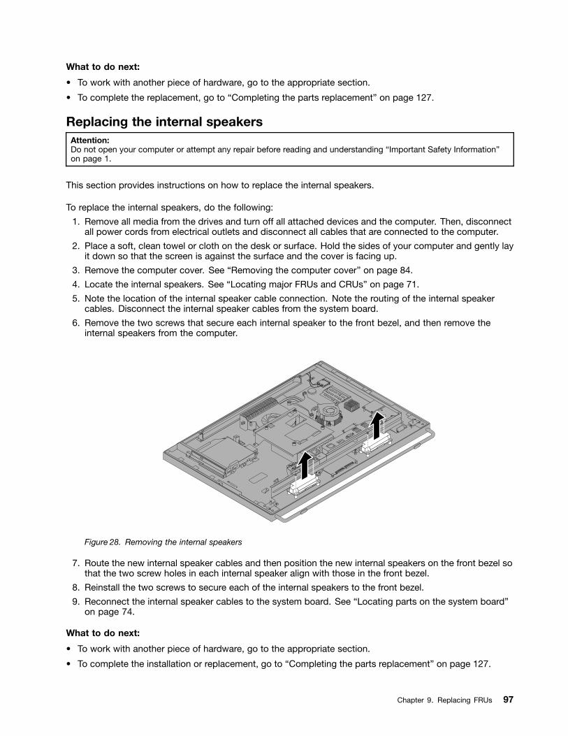
What to do next:
To work with another piece of hardware, go to the appropriate section.
To complete the replacement, go to Completing the parts replacement on page 127.
Replacing the internal speakersAttention:Do not open your computer or attempt any repair before reading and understanding Important Safety Informationon page 1.
This section provides instructions on how to replace the internal speakers.
To replace the internal speakers, do the following:
1. Remove all media from the drives and turn off all attached devices and the computer. Then, disconnectall power cords from electrical outlets and disconnect all cables that are connected to the computer.
2. Place a soft, clean towel or cloth on the desk or surface. Hold the sides of your computer and gently layit down so that the screen is against the surface and the cover is facing up.
3. Remove the computer cover. See Removing the computer cover on page 84.
4. Locate the internal speakers. See Locating major FRUs and CRUs on page 71.
5. Note the location of the internal speaker cable connection. Note the routing of the internal speakercables. Disconnect the internal speaker cables from the system board.
6. Remove the two screws that secure each internal speaker to the front bezel, and then remove theinternal speakers from the computer.
Figure 28. Removing the internal speakers
7. Route the new internal speaker cables and then position the new internal speakers on the front bezel sothat the two screw holes in each internal speaker align with those in the front bezel.
8. Reinstall the two screws to secure each of the internal speakers to the front bezel.
9. Reconnect the internal speaker cables to the system board. See Locating parts on the system boardon page 74.
What to do next:
To work with another piece of hardware, go to the appropriate section.
To complete the installation or replacement, go to Completing the parts replacement on page 127.
Chapter 9. Replacing FRUs 97
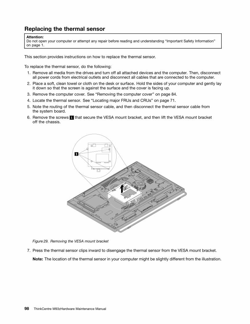
Replacing the thermal sensorAttention:Do not open your computer or attempt any repair before reading and understanding Important Safety Informationon page 1.
This section provides instructions on how to replace the thermal sensor.
To replace the thermal sensor, do the following:
1. Remove all media from the drives and turn off all attached devices and the computer. Then, disconnectall power cords from electrical outlets and disconnect all cables that are connected to the computer.
2. Place a soft, clean towel or cloth on the desk or surface. Hold the sides of your computer and gently layit down so that the screen is against the surface and the cover is facing up.
3. Remove the computer cover. See Removing the computer cover on page 84.
4. Locate the thermal sensor. See Locating major FRUs and CRUs on page 71.
5. Note the routing of the thermal sensor cable, and then disconnect the thermal sensor cable fromthe system board.
6. Remove the screws 1 that secure the VESA mount bracket, and then lift the VESA mount bracketoff the chassis.
Figure 29. Removing the VESA mount bracket
7. Press the thermal sensor clips inward to disengage the thermal sensor from the VESA mount bracket.
Note: The location of the thermal sensor in your computer might be slightly different from the illustration.
98 ThinkCentre M93zHardware Maintenance Manual
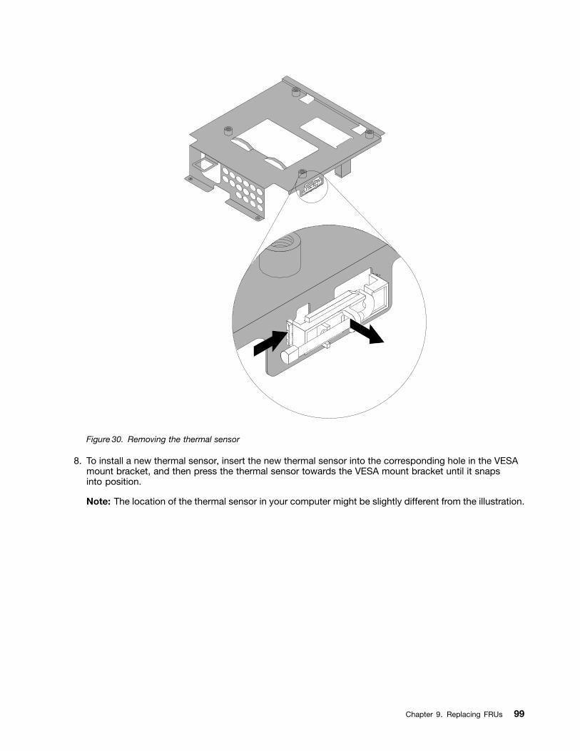
Figure 30. Removing the thermal sensor
8. To install a new thermal sensor, insert the new thermal sensor into the corresponding hole in the VESAmount bracket, and then press the thermal sensor towards the VESA mount bracket until it snapsinto position.
Note: The location of the thermal sensor in your computer might be slightly different from the illustration.
Chapter 9. Replacing FRUs 99
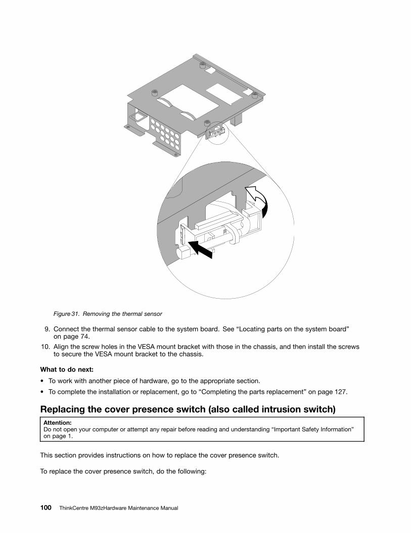
Figure 31. Removing the thermal sensor
9. Connect the thermal sensor cable to the system board. See Locating parts on the system boardon page 74.
10. Align the screw holes in the VESA mount bracket with those in the chassis, and then install the screwsto secure the VESA mount bracket to the chassis.
What to do next:
To work with another piece of hardware, go to the appropriate section.
To complete the installation or replacement, go to Completing the parts replacement on page 127.
Replacing the cover presence switch (also called intrusion switch)Attention:Do not open your computer or attempt any repair before reading and understanding Important Safety Informationon page 1.
This section provides instructions on how to replace the cover presence switch.
To replace the cover presence switch, do the following:
100 ThinkCentre M93zHardware Maintenance Manual
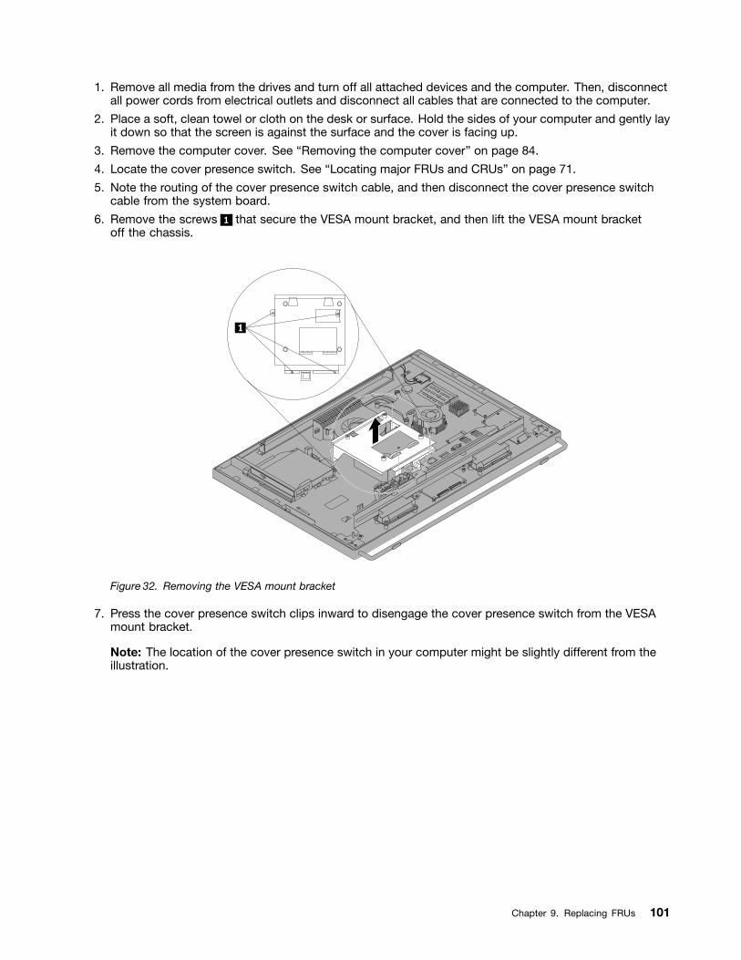
1. Remove all media from the drives and turn off all attached devices and the computer. Then, disconnectall power cords from electrical outlets and disconnect all cables that are connected to the computer.
2. Place a soft, clean towel or cloth on the desk or surface. Hold the sides of your computer and gently layit down so that the screen is against the surface and the cover is facing up.
3. Remove the computer cover. See Removing the computer cover on page 84.
4. Locate the cover presence switch. See Locating major FRUs and CRUs on page 71.
5. Note the routing of the cover presence switch cable, and then disconnect the cover presence switchcable from the system board.
6. Remove the screws 1 that secure the VESA mount bracket, and then lift the VESA mount bracketoff the chassis.
Figure 32. Removing the VESA mount bracket
7. Press the cover presence switch clips inward to disengage the cover presence switch from the VESAmount bracket.
Note: The location of the cover presence switch in your computer might be slightly different from theillustration.
Chapter 9. Replacing FRUs 101
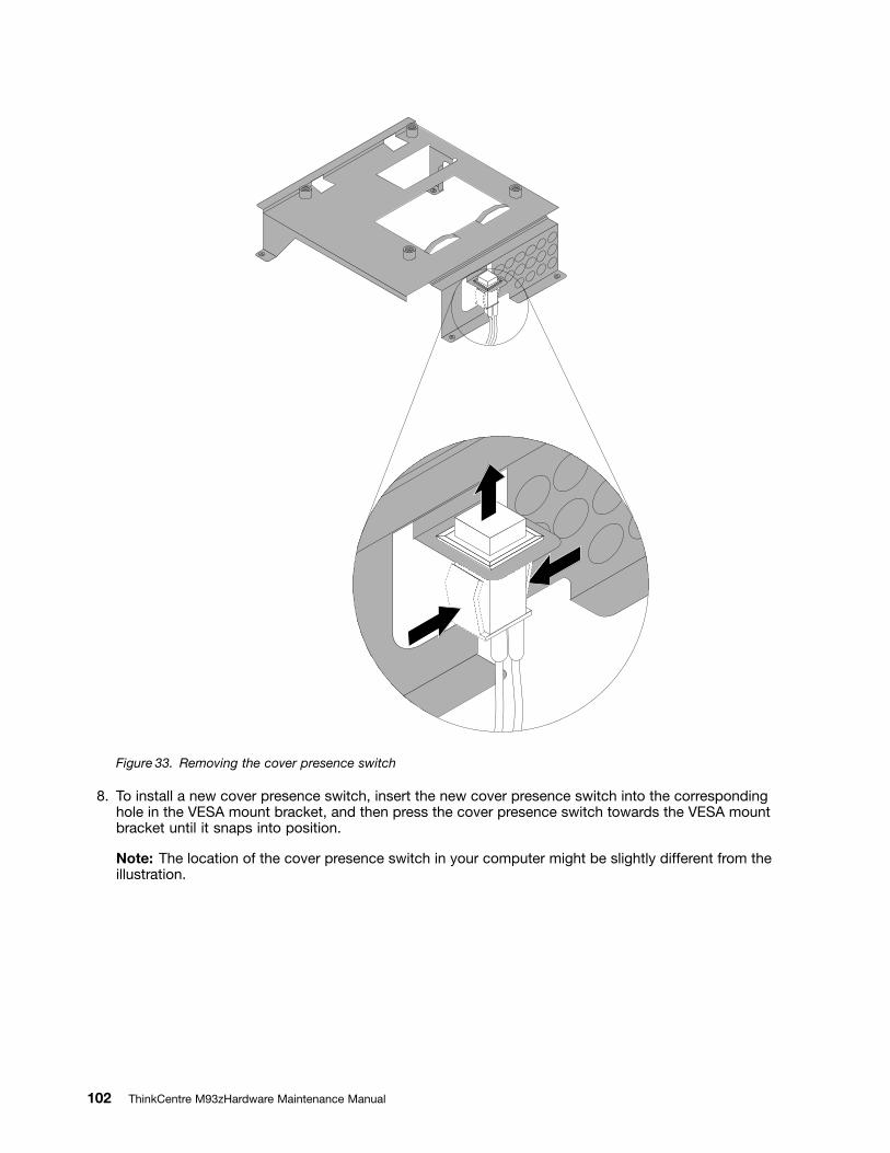
Figure 33. Removing the cover presence switch
8. To install a new cover presence switch, insert the new cover presence switch into the correspondinghole in the VESA mount bracket, and then press the cover presence switch towards the VESA mountbracket until it snaps into position.
Note: The location of the cover presence switch in your computer might be slightly different from theillustration.
102 ThinkCentre M93zHardware Maintenance Manual
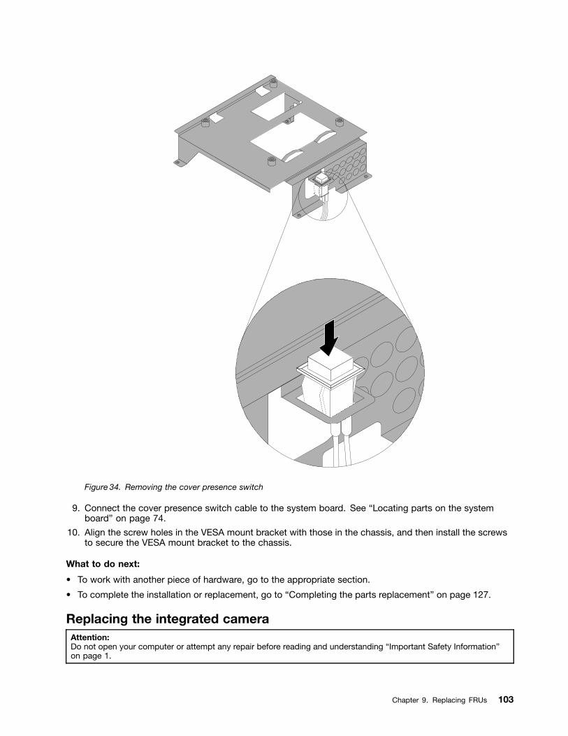
Figure 34. Removing the cover presence switch
9. Connect the cover presence switch cable to the system board. See Locating parts on the systemboard on page 74.
10. Align the screw holes in the VESA mount bracket with those in the chassis, and then install the screwsto secure the VESA mount bracket to the chassis.
What to do next:
To work with another piece of hardware, go to the appropriate section.
To complete the installation or replacement, go to Completing the parts replacement on page 127.
Replacing the integrated cameraAttention:Do not open your computer or attempt any repair before reading and understanding Important Safety Informationon page 1.
Chapter 9. Replacing FRUs 103
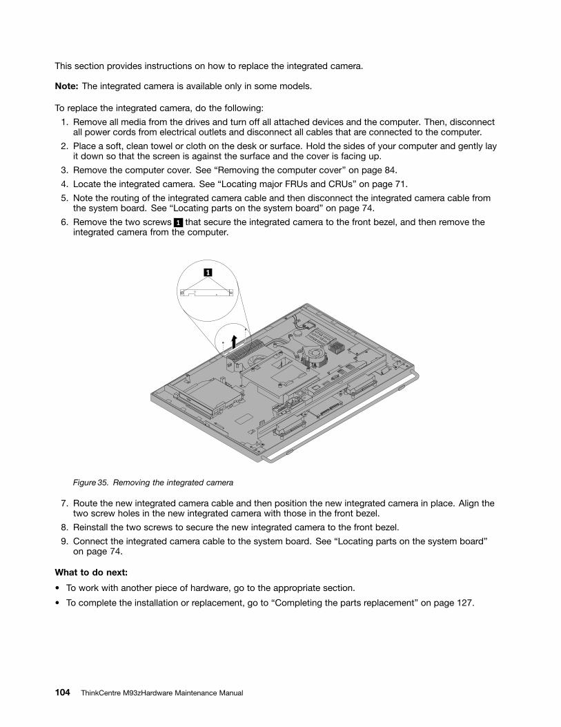
This section provides instructions on how to replace the integrated camera.
Note: The integrated camera is available only in some models.
To replace the integrated camera, do the following:
1. Remove all media from the drives and turn off all attached devices and the computer. Then, disconnectall power cords from electrical outlets and disconnect all cables that are connected to the computer.
2. Place a soft, clean towel or cloth on the desk or surface. Hold the sides of your computer and gently layit down so that the screen is against the surface and the cover is facing up.
3. Remove the computer cover. See Removing the computer cover on page 84.
4. Locate the integrated camera. See Locating major FRUs and CRUs on page 71.
5. Note the routing of the integrated camera cable and then disconnect the integrated camera cable fromthe system board. See Locating parts on the system board on page 74.
6. Remove the two screws 1 that secure the integrated camera to the front bezel, and then remove theintegrated camera from the computer.
Figure 35. Removing the integrated camera
7. Route the new integrated camera cable and then position the new integrated camera in place. Align thetwo screw holes in the new integrated camera with those in the front bezel.
8. Reinstall the two screws to secure the new integrated camera to the front bezel.
9. Connect the integrated camera cable to the system board. See Locating parts on the system boardon page 74.
What to do next:
To work with another piece of hardware, go to the appropriate section.
To complete the installation or replacement, go to Completing the parts replacement on page 127.
104 ThinkCentre M93zHardware Maintenance Manual
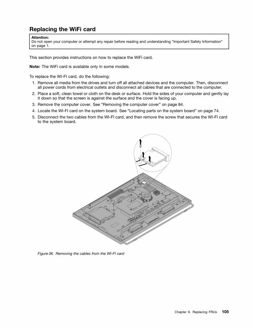
Replacing the WiFi cardAttention:Do not open your computer or attempt any repair before reading and understanding Important Safety Informationon page 1.
This section provides instructions on how to replace the WiFi card.
Note: The WiFi card is available only in some models.
To replace the WI-FI card, do the following:
1. Remove all media from the drives and turn off all attached devices and the computer. Then, disconnectall power cords from electrical outlets and disconnect all cables that are connected to the computer.
2. Place a soft, clean towel or cloth on the desk or surface. Hold the sides of your computer and gently layit down so that the screen is against the surface and the cover is facing up.
3. Remove the computer cover. See Removing the computer cover on page 84.
4. Locate the WI-FI card on the system board. See Locating parts on the system board on page 74.
5. Disconnect the two cables from the WI-FI card, and then remove the screw that secures the WI-FI cardto the system board.
Figure 36. Removing the cables from the WI-FI card
Chapter 9. Replacing FRUs 105
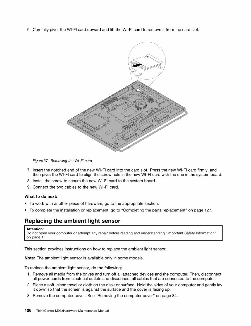
6. Carefully pivot the WI-FI card upward and lift the WI-FI card to remove it from the card slot.
Figure 37. Removing the WI-FI card
7. Insert the notched end of the new WI-FI card into the card slot. Press the new WI-FI card rmly, andthen pivot the WI-FI card to align the screw hole in the new WI-FI card with the one in the system board.
8. Install the screw to secure the new WI-FI card to the system board.
9. Connect the two cables to the new WI-FI card.
What to do next:
To work with another piece of hardware, go to the appropriate section.
To complete the installation or replacement, go to Completing the parts replacement on page 127.
Replacing the ambient light sensorAttention:Do not open your computer or attempt any repair before reading and understanding Important Safety Informationon page 1.
This section provides instructions on how to replace the ambient light sensor.
Note: The ambient light sensor is available only in some models.
To replace the ambient light sensor, do the following:
1. Remove all media from the drives and turn off all attached devices and the computer. Then, disconnectall power cords from electrical outlets and disconnect all cables that are connected to the computer.
2. Place a soft, clean towel or cloth on the desk or surface. Hold the sides of your computer and gently layit down so that the screen is against the surface and the cover is facing up.
3. Remove the computer cover. See Removing the computer cover on page 84.
106 ThinkCentre M93zHardware Maintenance Manual
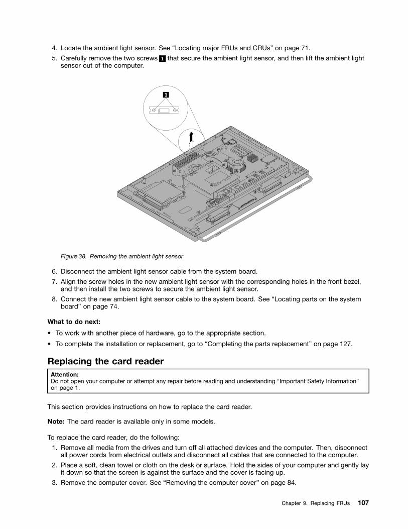
4. Locate the ambient light sensor. See Locating major FRUs and CRUs on page 71.
5. Carefully remove the two screws 1 that secure the ambient light sensor, and then lift the ambient lightsensor out of the computer.
Figure 38. Removing the ambient light sensor
6. Disconnect the ambient light sensor cable from the system board.
7. Align the screw holes in the new ambient light sensor with the corresponding holes in the front bezel,and then install the two screws to secure the ambient light sensor.
8. Connect the new ambient light sensor cable to the system board. See Locating parts on the systemboard on page 74.
What to do next:
To work with another piece of hardware, go to the appropriate section.
To complete the installation or replacement, go to Completing the parts replacement on page 127.
Replacing the card readerAttention:Do not open your computer or attempt any repair before reading and understanding Important Safety Informationon page 1.
This section provides instructions on how to replace the card reader.
Note: The card reader is available only in some models.
To replace the card reader, do the following:
1. Remove all media from the drives and turn off all attached devices and the computer. Then, disconnectall power cords from electrical outlets and disconnect all cables that are connected to the computer.
2. Place a soft, clean towel or cloth on the desk or surface. Hold the sides of your computer and gently layit down so that the screen is against the surface and the cover is facing up.
3. Remove the computer cover. See Removing the computer cover on page 84.
Chapter 9. Replacing FRUs 107
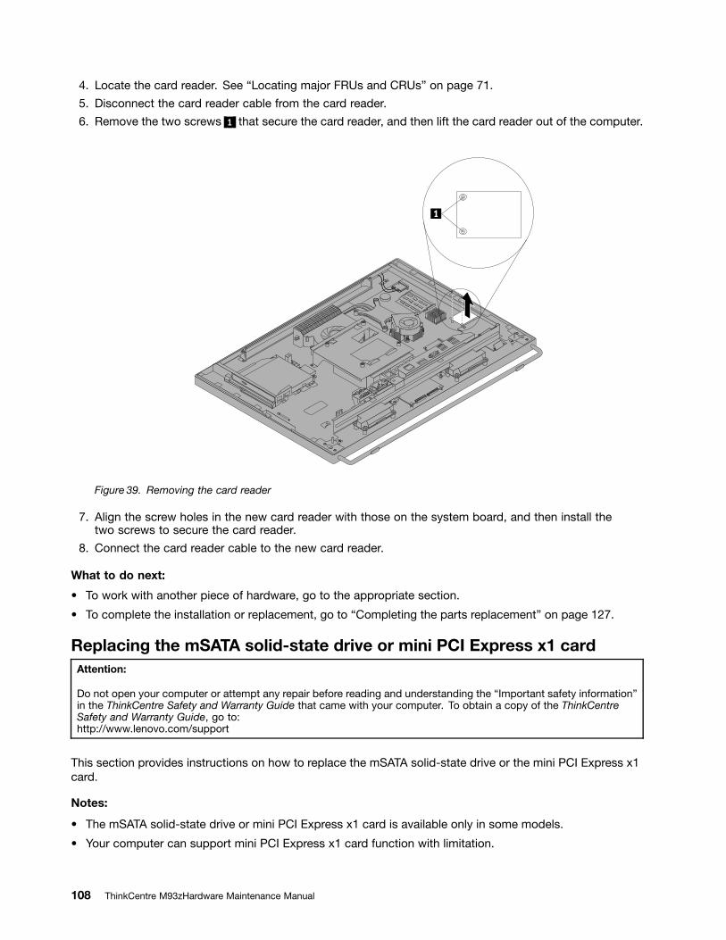
4. Locate the card reader. See Locating major FRUs and CRUs on page 71.
5. Disconnect the card reader cable from the card reader.
6. Remove the two screws 1 that secure the card reader, and then lift the card reader out of the computer.
Figure 39. Removing the card reader
7. Align the screw holes in the new card reader with those on the system board, and then install thetwo screws to secure the card reader.
8. Connect the card reader cable to the new card reader.
What to do next:
To work with another piece of hardware, go to the appropriate section.
To complete the installation or replacement, go to Completing the parts replacement on page 127.
Replacing the mSATA solid-state drive or mini PCI Express x1 cardAttention:
Do not open your computer or attempt any repair before reading and understanding the Important safety informationin the ThinkCentre Safety and Warranty Guide that came with your computer. To obtain a copy of the ThinkCentreSafety and Warranty Guide, go to:http://www.lenovo.com/support
This section provides instructions on how to replace the mSATA solid-state drive or the mini PCI Express x1card.
Notes:
The mSATA solid-state drive or mini PCI Express x1 card is available only in some models.
Your computer can support mini PCI Express x1 card function with limitation.
108 ThinkCentre M93zHardware Maintenance Manual
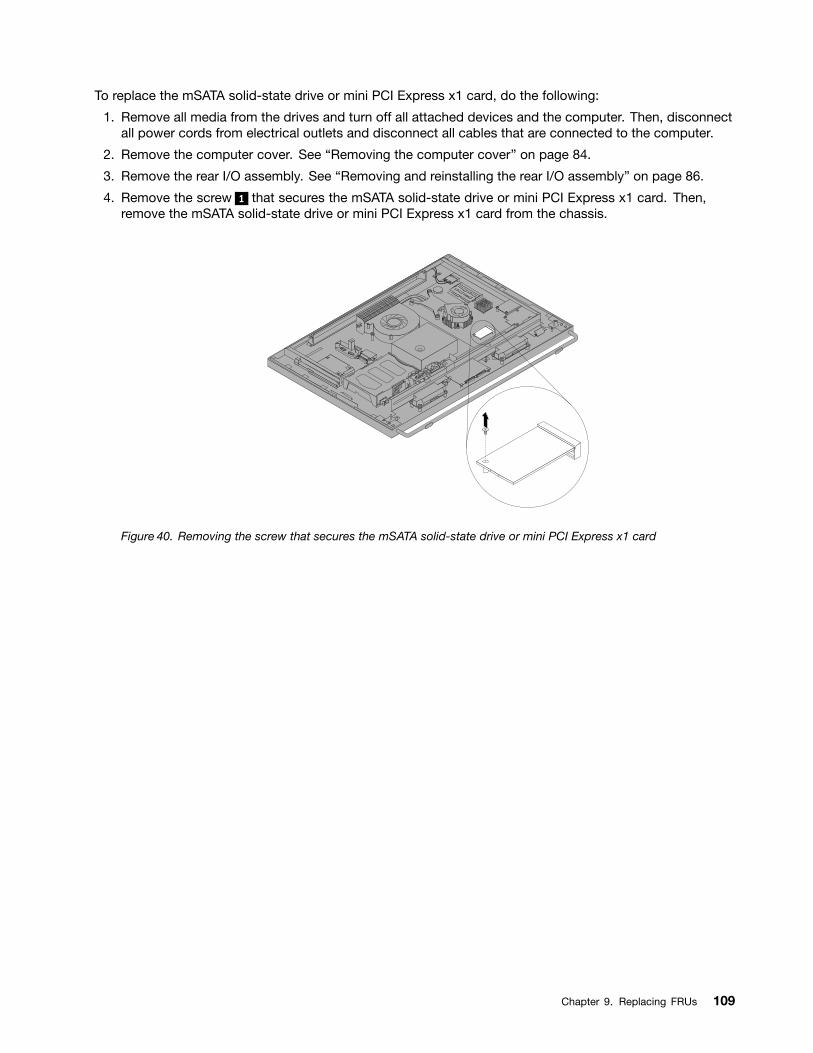
To replace the mSATA solid-state drive or mini PCI Express x1 card, do the following:
1. Remove all media from the drives and turn off all attached devices and the computer. Then, disconnectall power cords from electrical outlets and disconnect all cables that are connected to the computer.
2. Remove the computer cover. See Removing the computer cover on page 84.
3. Remove the rear I/O assembly. See Removing and reinstalling the rear I/O assembly on page 86.
4. Remove the screw 1 that secures the mSATA solid-state drive or mini PCI Express x1 card. Then,remove the mSATA solid-state drive or mini PCI Express x1 card from the chassis.
Figure 40. Removing the screw that secures the mSATA solid-state drive or mini PCI Express x1 card
Chapter 9. Replacing FRUs 109
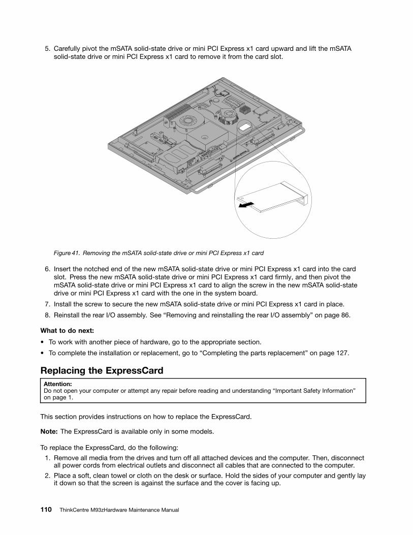
5. Carefully pivot the mSATA solid-state drive or mini PCI Express x1 card upward and lift the mSATAsolid-state drive or mini PCI Express x1 card to remove it from the card slot.
Figure 41. Removing the mSATA solid-state drive or mini PCI Express x1 card
6. Insert the notched end of the new mSATA solid-state drive or mini PCI Express x1 card into the cardslot. Press the new mSATA solid-state drive or mini PCI Express x1 card rmly, and then pivot themSATA solid-state drive or mini PCI Express x1 card to align the screw in the new mSATA solid-statedrive or mini PCI Express x1 card with the one in the system board.
7. Install the screw to secure the new mSATA solid-state drive or mini PCI Express x1 card in place.
8. Reinstall the rear I/O assembly. See Removing and reinstalling the rear I/O assembly on page 86.
What to do next:
To work with another piece of hardware, go to the appropriate section.
To complete the installation or replacement, go to Completing the parts replacement on page 127.
Replacing the ExpressCardAttention:Do not open your computer or attempt any repair before reading and understanding Important Safety Informationon page 1.
This section provides instructions on how to replace the ExpressCard.
Note: The ExpressCard is available only in some models.
To replace the ExpressCard, do the following:
1. Remove all media from the drives and turn off all attached devices and the computer. Then, disconnectall power cords from electrical outlets and disconnect all cables that are connected to the computer.
2. Place a soft, clean towel or cloth on the desk or surface. Hold the sides of your computer and gently layit down so that the screen is against the surface and the cover is facing up.
110 ThinkCentre M93zHardware Maintenance Manual
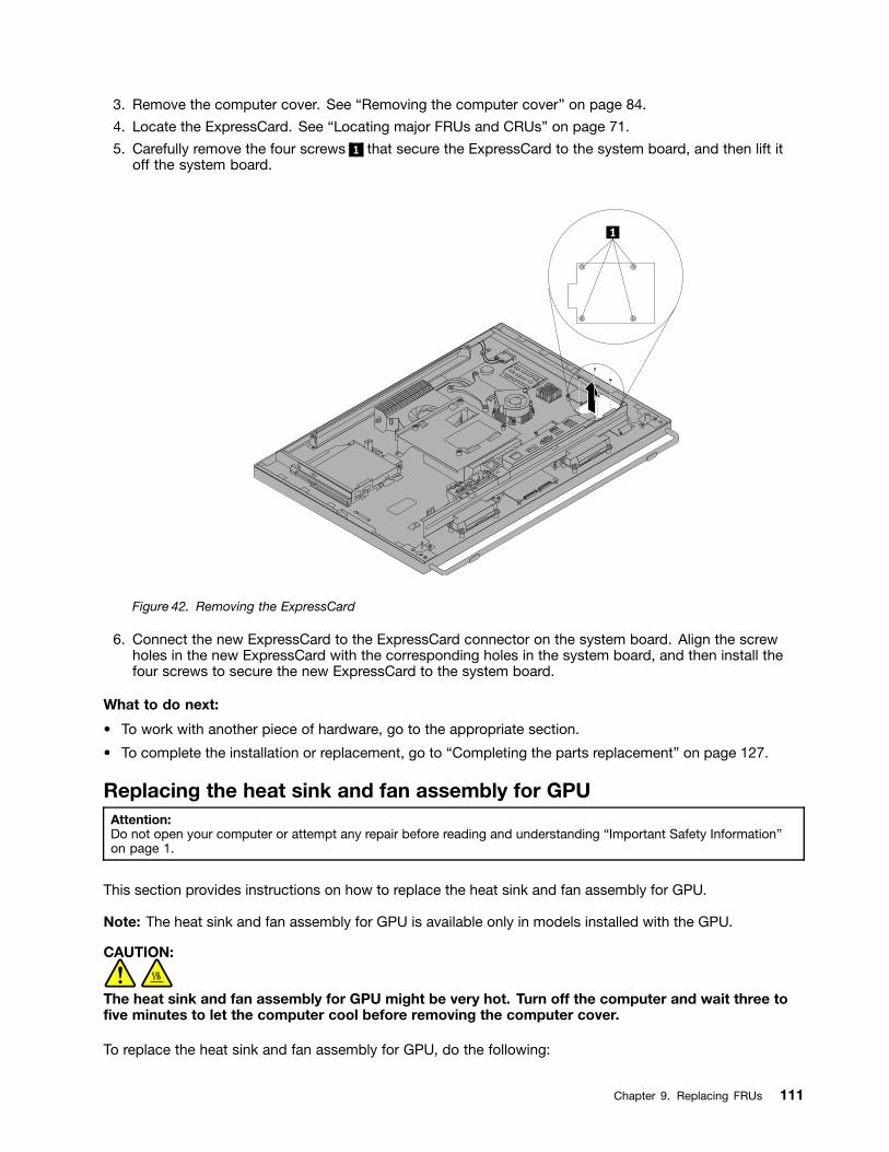
3. Remove the computer cover. See Removing the computer cover on page 84.
4. Locate the ExpressCard. See Locating major FRUs and CRUs on page 71.
5. Carefully remove the four screws 1 that secure the ExpressCard to the system board, and then lift itoff the system board.
Figure 42. Removing the ExpressCard
6. Connect the new ExpressCard to the ExpressCard connector on the system board. Align the screwholes in the new ExpressCard with the corresponding holes in the system board, and then install thefour screws to secure the new ExpressCard to the system board.
What to do next:
To work with another piece of hardware, go to the appropriate section.
To complete the installation or replacement, go to Completing the parts replacement on page 127.
Replacing the heat sink and fan assembly for GPUAttention:Do not open your computer or attempt any repair before reading and understanding Important Safety Informationon page 1.
This section provides instructions on how to replace the heat sink and fan assembly for GPU.
Note: The heat sink and fan assembly for GPU is available only in models installed with the GPU.
CAUTION:
The heat sink and fan assembly for GPU might be very hot. Turn off the computer and wait three tove minutes to let the computer cool before removing the computer cover.
To replace the heat sink and fan assembly for GPU, do the following:
Chapter 9. Replacing FRUs 111
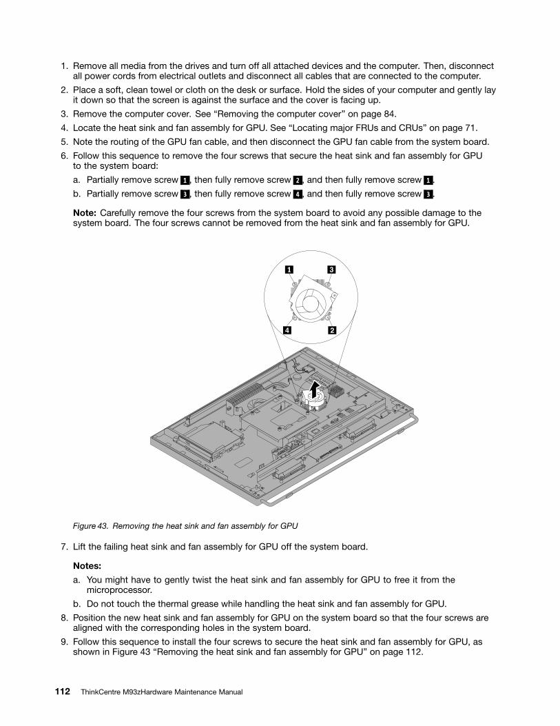
1. Remove all media from the drives and turn off all attached devices and the computer. Then, disconnectall power cords from electrical outlets and disconnect all cables that are connected to the computer.
2. Place a soft, clean towel or cloth on the desk or surface. Hold the sides of your computer and gently layit down so that the screen is against the surface and the cover is facing up.
3. Remove the computer cover. See Removing the computer cover on page 84.
4. Locate the heat sink and fan assembly for GPU. See Locating major FRUs and CRUs on page 71.
5. Note the routing of the GPU fan cable, and then disconnect the GPU fan cable from the system board.
6. Follow this sequence to remove the four screws that secure the heat sink and fan assembly for GPUto the system board:
a. Partially remove screw 1 , then fully remove screw 2 , and then fully remove screw 1 .
b. Partially remove screw 3 , then fully remove screw 4 , and then fully remove screw 3 .
Note: Carefully remove the four screws from the system board to avoid any possible damage to thesystem board. The four screws cannot be removed from the heat sink and fan assembly for GPU.
Figure 43. Removing the heat sink and fan assembly for GPU
7. Lift the failing heat sink and fan assembly for GPU off the system board.
Notes:
a. You might have to gently twist the heat sink and fan assembly for GPU to free it from themicroprocessor.
b. Do not touch the thermal grease while handling the heat sink and fan assembly for GPU.
8. Position the new heat sink and fan assembly for GPU on the system board so that the four screws arealigned with the corresponding holes in the system board.
9. Follow this sequence to install the four screws to secure the heat sink and fan assembly for GPU, asshown in Figure 43 Removing the heat sink and fan assembly for GPU on page 112.
112 ThinkCentre M93zHardware Maintenance Manual
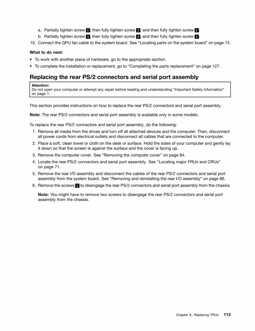
a. Partially tighten screw 1 , then fully tighten screw 2 , and then fully tighten screw 1 .
b. Partially tighten screw 3 , then fully tighten screw 4 , and then fully tighten screw 3 .
10. Connect the GPU fan cable to the system board. See Locating parts on the system board on page 74.
What to do next:
To work with another piece of hardware, go to the appropriate section.
To complete the installation or replacement, go to Completing the parts replacement on page 127.
Replacing the rear PS/2 connectors and serial port assemblyAttention:Do not open your computer or attempt any repair before reading and understanding Important Safety Informationon page 1.
This section provides instructions on how to replace the rear PS/2 connectors and serial port assembly.
Note: The rear PS/2 connectors and serial port assembly is available only in some models.
To replace the rear PS/2 connectors and serial port assembly, do the following:
1. Remove all media from the drives and turn off all attached devices and the computer. Then, disconnectall power cords from electrical outlets and disconnect all cables that are connected to the computer.
2. Place a soft, clean towel or cloth on the desk or surface. Hold the sides of your computer and gently layit down so that the screen is against the surface and the cover is facing up.
3. Remove the computer cover. See Removing the computer cover on page 84.
4. Locate the rear PS/2 connectors and serial port assembly. See Locating major FRUs and CRUson page 71.
5. Remove the rear I/O assembly and disconnect the cables of the rear PS/2 connectors and serial portassembly from the system board. See Removing and reinstalling the rear I/O assembly on page 86.
6. Remove the screws 1 to disengage the rear PS/2 connectors and serial port assembly from the chassis.
Note: You might have to remove two screws to disengage the rear PS/2 connectors and serial portassembly from the chassis.
Chapter 9. Replacing FRUs 113
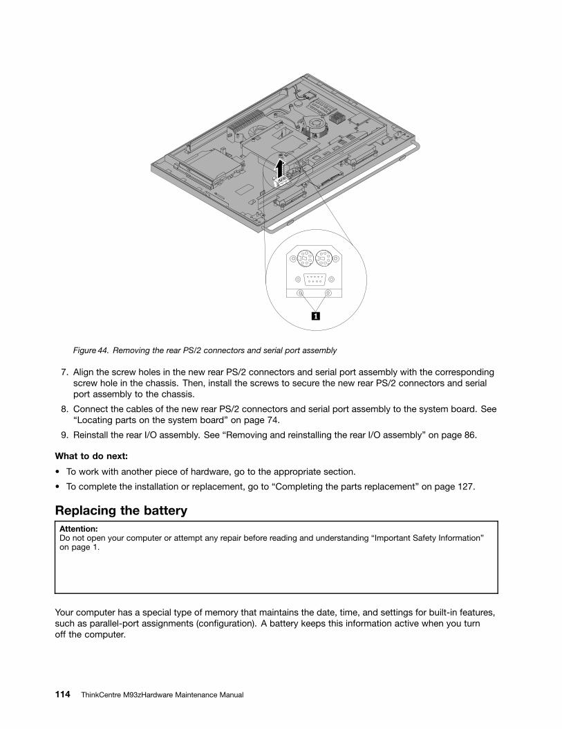
Figure 44. Removing the rear PS/2 connectors and serial port assembly
7. Align the screw holes in the new rear PS/2 connectors and serial port assembly with the correspondingscrew hole in the chassis. Then, install the screws to secure the new rear PS/2 connectors and serialport assembly to the chassis.
8. Connect the cables of the new rear PS/2 connectors and serial port assembly to the system board. SeeLocating parts on the system board on page 74.
9. Reinstall the rear I/O assembly. See Removing and reinstalling the rear I/O assembly on page 86.
What to do next:
To work with another piece of hardware, go to the appropriate section.
To complete the installation or replacement, go to Completing the parts replacement on page 127.
Replacing the batteryAttention:Do not open your computer or attempt any repair before reading and understanding Important Safety Informationon page 1.
Your computer has a special type of memory that maintains the date, time, and settings for built-in features,such as parallel-port assignments (con guration). A battery keeps this information active when you turnoff the computer.
114 ThinkCentre M93zHardware Maintenance Manual
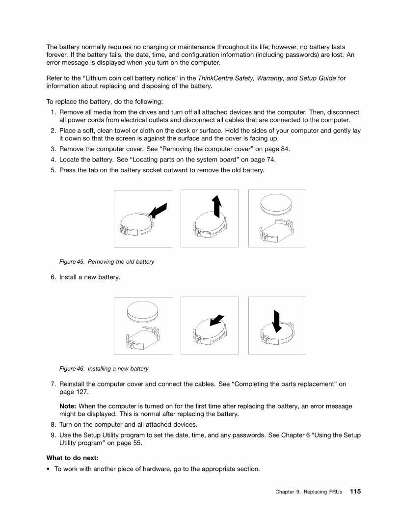
The battery normally requires no charging or maintenance throughout its life; however, no battery lastsforever. If the battery fails, the date, time, and con guration information (including passwords) are lost. Anerror message is displayed when you turn on the computer.
Refer to the Lithium coin cell battery notice in the ThinkCentre Safety, Warranty, and Setup Guide forinformation about replacing and disposing of the battery.
To replace the battery, do the following:
1. Remove all media from the drives and turn off all attached devices and the computer. Then, disconnectall power cords from electrical outlets and disconnect all cables that are connected to the computer.
2. Place a soft, clean towel or cloth on the desk or surface. Hold the sides of your computer and gently layit down so that the screen is against the surface and the cover is facing up.
3. Remove the computer cover. See Removing the computer cover on page 84.
4. Locate the battery. See Locating parts on the system board on page 74.
5. Press the tab on the battery socket outward to remove the old battery.
Figure 45. Removing the old battery
6. Install a new battery.
Figure 46. Installing a new battery
7. Reinstall the computer cover and connect the cables. See Completing the parts replacement onpage 127.
Note: When the computer is turned on for the rst time after replacing the battery, an error messagemight be displayed. This is normal after replacing the battery.
8. Turn on the computer and all attached devices.
9. Use the Setup Utility program to set the date, time, and any passwords. See Chapter 6 Using the SetupUtility program on page 55.
What to do next:
To work with another piece of hardware, go to the appropriate section.
Chapter 9. Replacing FRUs 115
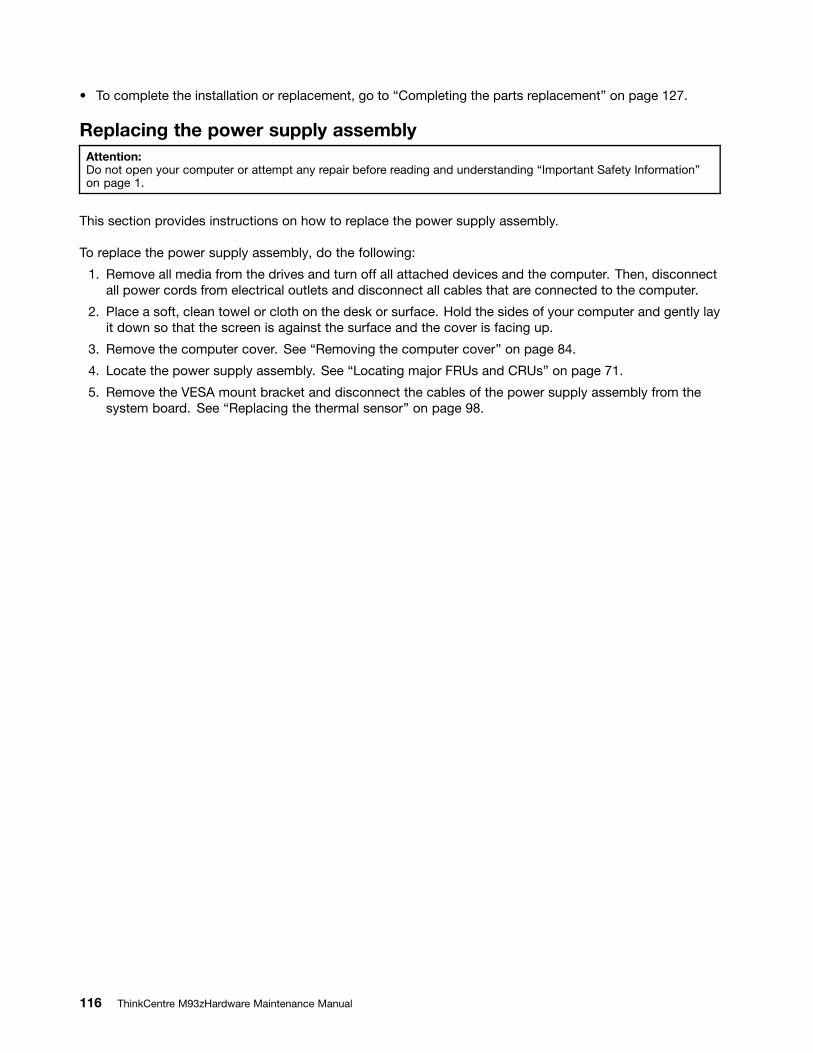
To complete the installation or replacement, go to Completing the parts replacement on page 127.
Replacing the power supply assemblyAttention:Do not open your computer or attempt any repair before reading and understanding Important Safety Informationon page 1.
This section provides instructions on how to replace the power supply assembly.
To replace the power supply assembly, do the following:
1. Remove all media from the drives and turn off all attached devices and the computer. Then, disconnectall power cords from electrical outlets and disconnect all cables that are connected to the computer.
2. Place a soft, clean towel or cloth on the desk or surface. Hold the sides of your computer and gently layit down so that the screen is against the surface and the cover is facing up.
3. Remove the computer cover. See Removing the computer cover on page 84.
4. Locate the power supply assembly. See Locating major FRUs and CRUs on page 71.
5. Remove the VESA mount bracket and disconnect the cables of the power supply assembly from thesystem board. See Replacing the thermal sensor on page 98.
116 ThinkCentre M93zHardware Maintenance Manual
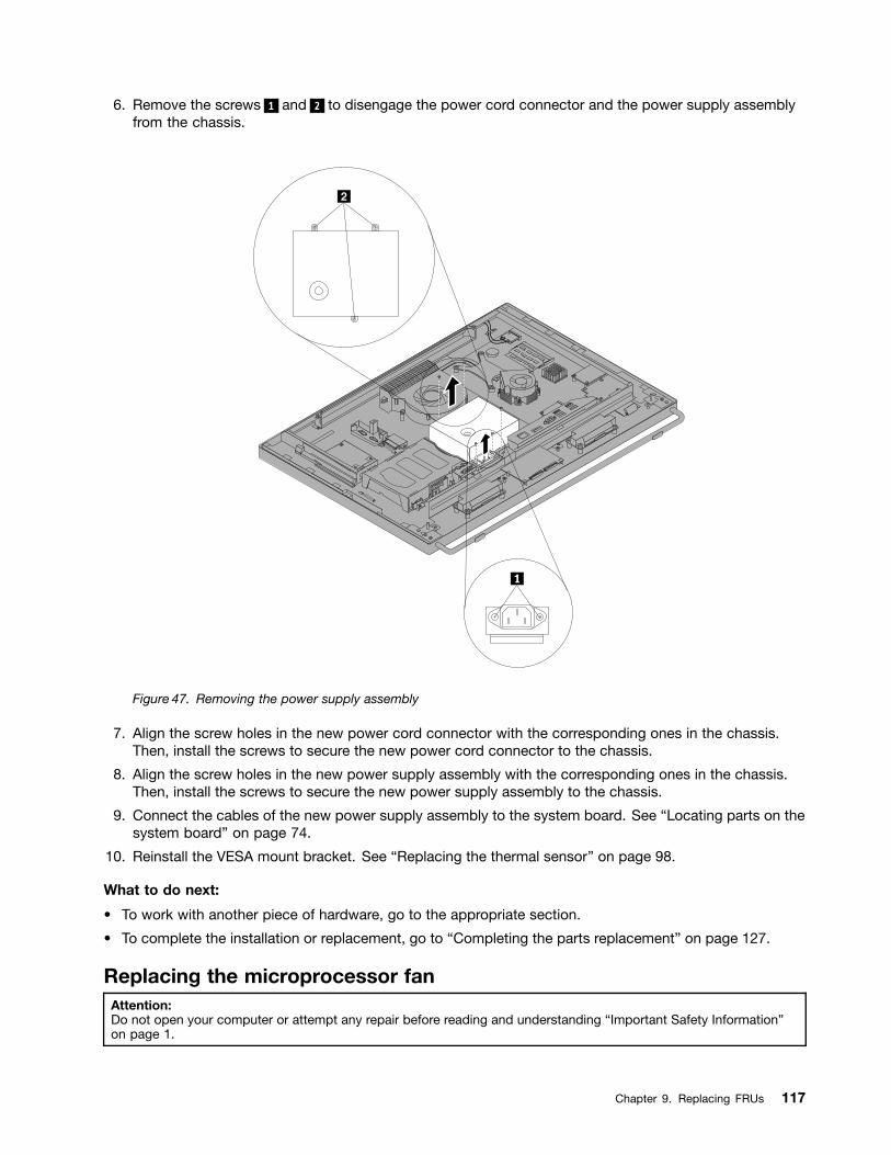
6. Remove the screws 1 and 2 to disengage the power cord connector and the power supply assemblyfrom the chassis.
Figure 47. Removing the power supply assembly
7. Align the screw holes in the new power cord connector with the corresponding ones in the chassis.Then, install the screws to secure the new power cord connector to the chassis.
8. Align the screw holes in the new power supply assembly with the corresponding ones in the chassis.Then, install the screws to secure the new power supply assembly to the chassis.
9. Connect the cables of the new power supply assembly to the system board. See Locating parts on thesystem board on page 74.
10. Reinstall the VESA mount bracket. See Replacing the thermal sensor on page 98.
What to do next:
To work with another piece of hardware, go to the appropriate section.
To complete the installation or replacement, go to Completing the parts replacement on page 127.
Replacing the microprocessor fanAttention:Do not open your computer or attempt any repair before reading and understanding Important Safety Informationon page 1.
Chapter 9. Replacing FRUs 117
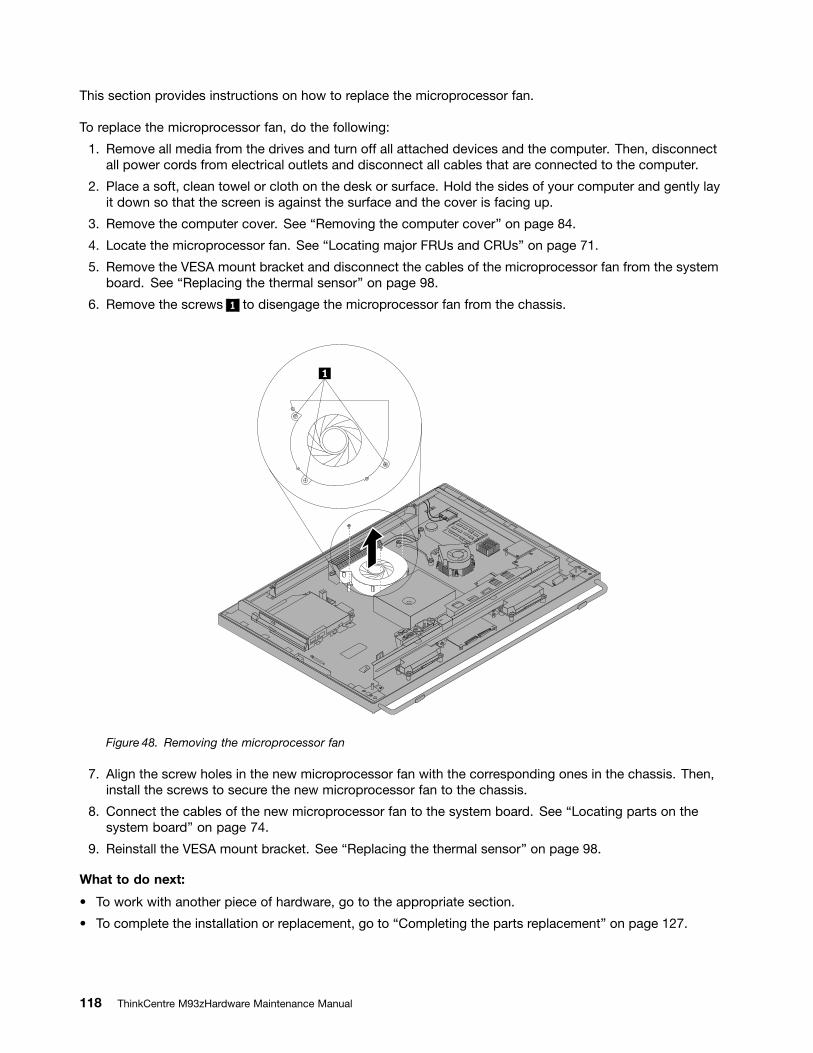
This section provides instructions on how to replace the microprocessor fan.
To replace the microprocessor fan, do the following:
1. Remove all media from the drives and turn off all attached devices and the computer. Then, disconnectall power cords from electrical outlets and disconnect all cables that are connected to the computer.
2. Place a soft, clean towel or cloth on the desk or surface. Hold the sides of your computer and gently layit down so that the screen is against the surface and the cover is facing up.
3. Remove the computer cover. See Removing the computer cover on page 84.
4. Locate the microprocessor fan. See Locating major FRUs and CRUs on page 71.
5. Remove the VESA mount bracket and disconnect the cables of the microprocessor fan from the systemboard. See Replacing the thermal sensor on page 98.
6. Remove the screws 1 to disengage the microprocessor fan from the chassis.
Figure 48. Removing the microprocessor fan
7. Align the screw holes in the new microprocessor fan with the corresponding ones in the chassis. Then,install the screws to secure the new microprocessor fan to the chassis.
8. Connect the cables of the new microprocessor fan to the system board. See Locating parts on thesystem board on page 74.
9. Reinstall the VESA mount bracket. See Replacing the thermal sensor on page 98.
What to do next:
To work with another piece of hardware, go to the appropriate section.
To complete the installation or replacement, go to Completing the parts replacement on page 127.
118 ThinkCentre M93zHardware Maintenance Manual
Replacing the LCD panelAttention:Do not open your computer or attempt any repair before reading and understanding Important Safety Informationon page 1.
This section provides instructions on how to replace the LCD panel.
To replace the LCD panel, do the following:
1. Remove all media from the drives and turn off all attached devices and the computer. Then, disconnectall power cords from electrical outlets and disconnect all cables that are connected to the computer.
2. Place a soft, clean towel or cloth on the desk or surface. Hold the sides of your computer and gently layit down so that the screen is against the surface and the cover is facing up.
3. Remove the computer cover. See Removing the computer cover on page 84.
4. Locate the LCD panel. See Locating major FRUs and CRUs on page 71.
5. Remove the frame foot. See Removing and reinstalling the frame foot
6. Remove the 21 screws that secure the LCD bracket to the front bezel.
Figure 49. Removing the LCD bracket
7. Disconnect the cables of the components secured to the front bezel from the system board. Then, liftthe LCD bracket off the front bezel.
8. Disconnect the LCD cables from the display connectors on the system board and the converter board.See Locating parts on the system board on page 74.
9. Connect the new LCD cables to the display connectors on the system board and the converter board.See Locating parts on the system board on page 74.
10. Position the LCD bracket over the front bezel, ensure that the screw holes in the LCD bracket align withthe mounting stands in the front bezel.
Chapter 9. Replacing FRUs 119
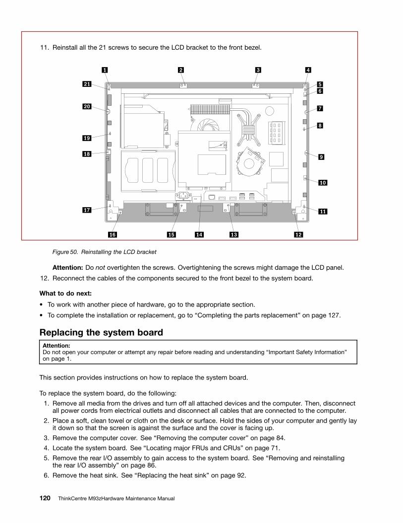
11. Reinstall all the 21 screws to secure the LCD bracket to the front bezel.
Figure 50. Reinstalling the LCD bracket
Attention: Do not overtighten the screws. Overtightening the screws might damage the LCD panel.
12. Reconnect the cables of the components secured to the front bezel to the system board.
What to do next:
To work with another piece of hardware, go to the appropriate section.
To complete the installation or replacement, go to Completing the parts replacement on page 127.
Replacing the system boardAttention:Do not open your computer or attempt any repair before reading and understanding Important Safety Informationon page 1.
This section provides instructions on how to replace the system board.
To replace the system board, do the following:
1. Remove all media from the drives and turn off all attached devices and the computer. Then, disconnectall power cords from electrical outlets and disconnect all cables that are connected to the computer.
2. Place a soft, clean towel or cloth on the desk or surface. Hold the sides of your computer and gently layit down so that the screen is against the surface and the cover is facing up.
3. Remove the computer cover. See Removing the computer cover on page 84.
4. Locate the system board. See Locating major FRUs and CRUs on page 71.
5. Remove the rear I/O assembly to gain access to the system board. See Removing and reinstallingthe rear I/O assembly on page 86.
6. Remove the heat sink. See Replacing the heat sink on page 92.
120 ThinkCentre M93zHardware Maintenance Manual
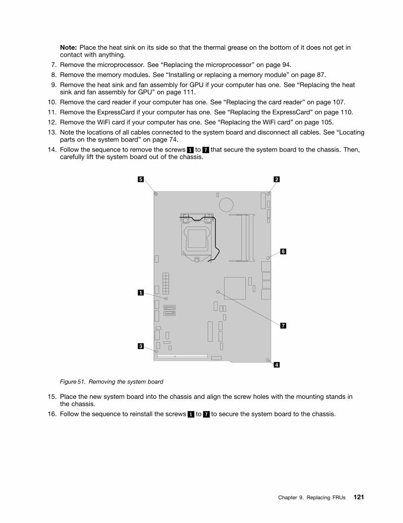
Note: Place the heat sink on its side so that the thermal grease on the bottom of it does not get incontact with anything.
7. Remove the microprocessor. See Replacing the microprocessor on page 94.
8. Remove the memory modules. See Installing or replacing a memory module on page 87.
9. Remove the heat sink and fan assembly for GPU if your computer has one. See Replacing the heatsink and fan assembly for GPU on page 111.
10. Remove the card reader if your computer has one. See Replacing the card reader on page 107.
11. Remove the ExpressCard if your computer has one. See Replacing the ExpressCard on page 110.
12. Remove the WiFi card if your computer has one. See Replacing the WiFi card on page 105.
13. Note the locations of all cables connected to the system board and disconnect all cables. See Locatingparts on the system board on page 74.
14. Follow the sequence to remove the screws 1 to 7 that secure the system board to the chassis. Then,carefully lift the system board out of the chassis.
Figure 51. Removing the system board
15. Place the new system board into the chassis and align the screw holes with the mounting stands inthe chassis.
16. Follow the sequence to reinstall the screws 1 to 7 to secure the system board to the chassis.
Chapter 9. Replacing FRUs 121
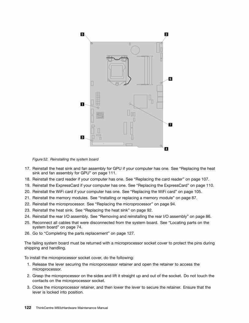
Figure 52. Reinstalling the system board
17. Reinstall the heat sink and fan assembly for GPU if your computer has one. See Replacing the heatsink and fan assembly for GPU on page 111.
18. Reinstall the card reader if your computer has one. See Replacing the card reader on page 107.
19. Reinstall the ExpressCard if your computer has one. See Replacing the ExpressCard on page 110.
20. Reinstall the WiFi card if your computer has one. See Replacing the WiFi card on page 105.
21. Reinstall the memory modules. See Installing or replacing a memory module on page 87.
22. Reinstall the microprocessor. See Replacing the microprocessor on page 94.
23. Reinstall the heat sink. See Replacing the heat sink on page 92.
24. Reinstall the rear I/O assembly. See Removing and reinstalling the rear I/O assembly on page 86.
25. Reconnect all cables that were disconnected from the system board. See Locating parts on thesystem board on page 74.
26. Go to Completing the parts replacement on page 127.
The failing system board must be returned with a microprocessor socket cover to protect the pins duringshipping and handling.
To install the microprocessor socket cover, do the following:
1. Release the lever securing the microprocessor retainer and open the retainer to access themicroprocessor.
2. Grasp the microprocessor on the sides and lift it straight up and out of the socket. Do not touch thecontacts on the microprocessor socket.
3. Close the microprocessor retainer, and then lower the lever to secure the retainer. Ensure that thelever is locked into position.
122 ThinkCentre M93zHardware Maintenance Manual
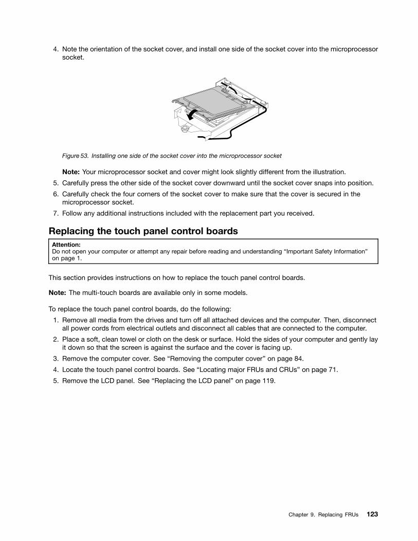
4. Note the orientation of the socket cover, and install one side of the socket cover into the microprocessorsocket.
Figure 53. Installing one side of the socket cover into the microprocessor socket
Note: Your microprocessor socket and cover might look slightly different from the illustration.
5. Carefully press the other side of the socket cover downward until the socket cover snaps into position.
6. Carefully check the four corners of the socket cover to make sure that the cover is secured in themicroprocessor socket.
7. Follow any additional instructions included with the replacement part you received.
Replacing the touch panel control boardsAttention:Do not open your computer or attempt any repair before reading and understanding Important Safety Informationon page 1.
This section provides instructions on how to replace the touch panel control boards.
Note: The multi-touch boards are available only in some models.
To replace the touch panel control boards, do the following:
1. Remove all media from the drives and turn off all attached devices and the computer. Then, disconnectall power cords from electrical outlets and disconnect all cables that are connected to the computer.
2. Place a soft, clean towel or cloth on the desk or surface. Hold the sides of your computer and gently layit down so that the screen is against the surface and the cover is facing up.
3. Remove the computer cover. See Removing the computer cover on page 84.
4. Locate the touch panel control boards. See Locating major FRUs and CRUs on page 71.
5. Remove the LCD panel. See Replacing the LCD panel on page 119.
Chapter 9. Replacing FRUs 123
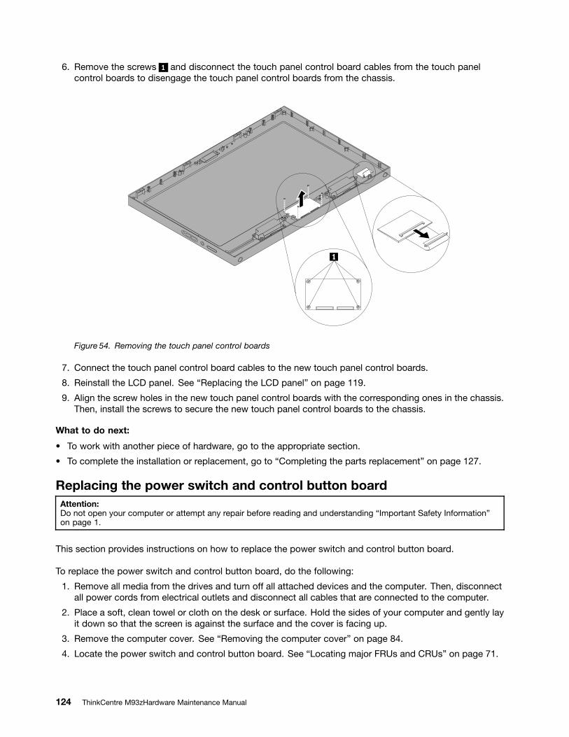
6. Remove the screws 1 and disconnect the touch panel control board cables from the touch panelcontrol boards to disengage the touch panel control boards from the chassis.
Figure 54. Removing the touch panel control boards
7. Connect the touch panel control board cables to the new touch panel control boards.
8. Reinstall the LCD panel. See Replacing the LCD panel on page 119.
9. Align the screw holes in the new touch panel control boards with the corresponding ones in the chassis.Then, install the screws to secure the new touch panel control boards to the chassis.
What to do next:
To work with another piece of hardware, go to the appropriate section.
To complete the installation or replacement, go to Completing the parts replacement on page 127.
Replacing the power switch and control button boardAttention:Do not open your computer or attempt any repair before reading and understanding Important Safety Informationon page 1.
This section provides instructions on how to replace the power switch and control button board.
To replace the power switch and control button board, do the following:
1. Remove all media from the drives and turn off all attached devices and the computer. Then, disconnectall power cords from electrical outlets and disconnect all cables that are connected to the computer.
2. Place a soft, clean towel or cloth on the desk or surface. Hold the sides of your computer and gently layit down so that the screen is against the surface and the cover is facing up.
3. Remove the computer cover. See Removing the computer cover on page 84.
4. Locate the power switch and control button board. See Locating major FRUs and CRUs on page 71.
124 ThinkCentre M93zHardware Maintenance Manual
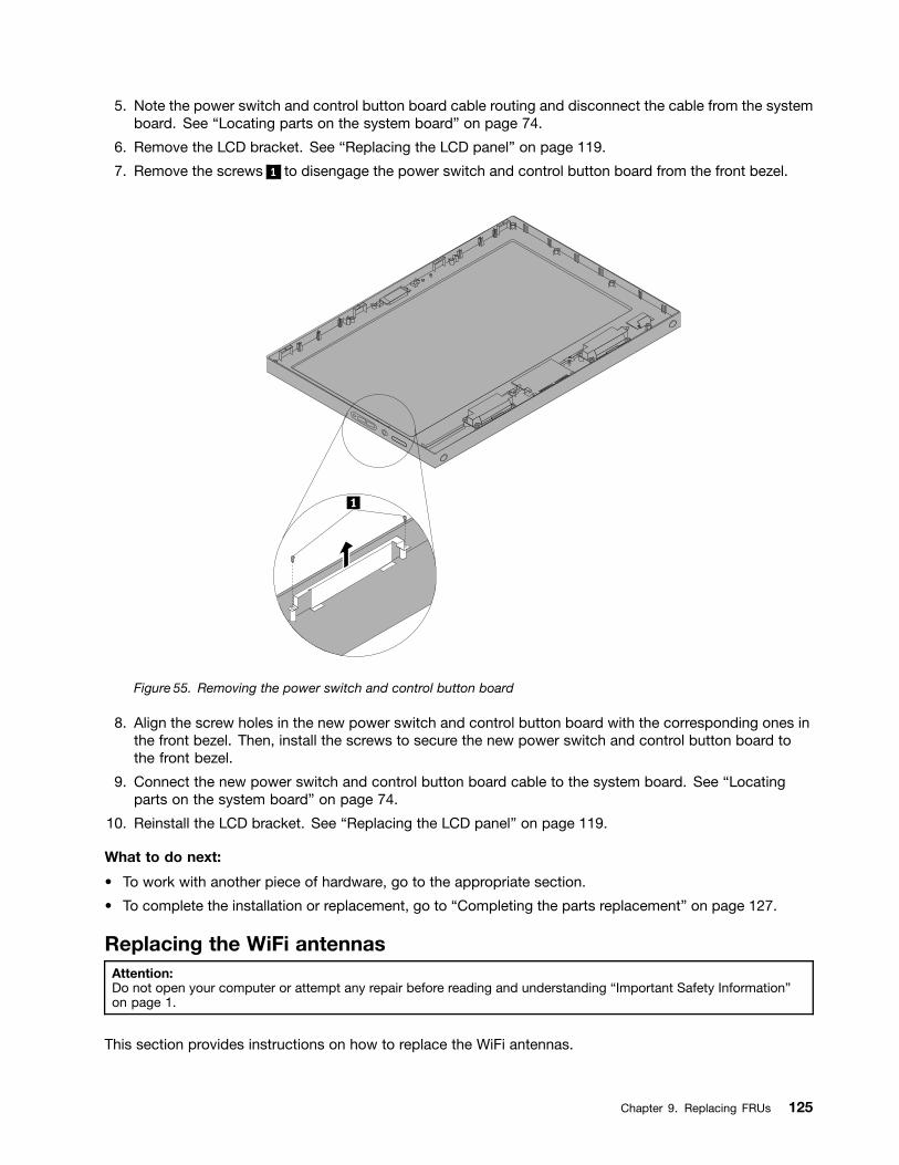
5. Note the power switch and control button board cable routing and disconnect the cable from the systemboard. See Locating parts on the system board on page 74.
6. Remove the LCD bracket. See Replacing the LCD panel on page 119.
7. Remove the screws 1 to disengage the power switch and control button board from the front bezel.
Figure 55. Removing the power switch and control button board
8. Align the screw holes in the new power switch and control button board with the corresponding ones inthe front bezel. Then, install the screws to secure the new power switch and control button board tothe front bezel.
9. Connect the new power switch and control button board cable to the system board. See Locatingparts on the system board on page 74.
10. Reinstall the LCD bracket. See Replacing the LCD panel on page 119.
What to do next:
To work with another piece of hardware, go to the appropriate section.
To complete the installation or replacement, go to Completing the parts replacement on page 127.
Replacing the WiFi antennasAttention:Do not open your computer or attempt any repair before reading and understanding Important Safety Informationon page 1.
This section provides instructions on how to replace the WiFi antennas.
Chapter 9. Replacing FRUs 125
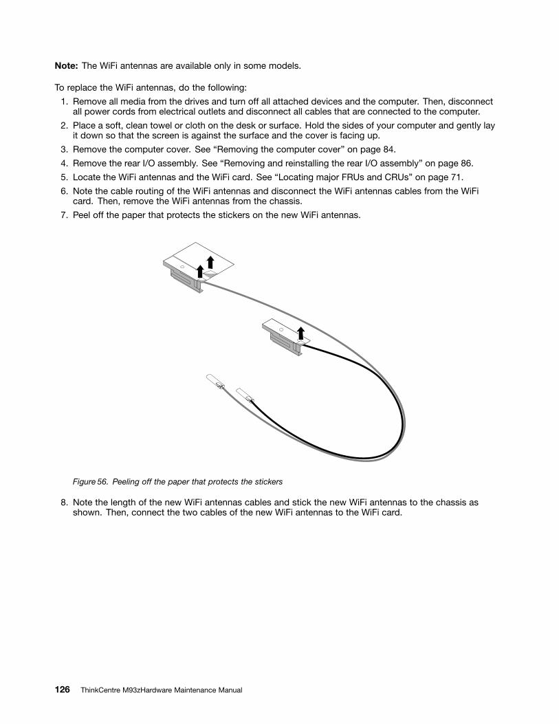
Note: The WiFi antennas are available only in some models.
To replace the WiFi antennas, do the following:
1. Remove all media from the drives and turn off all attached devices and the computer. Then, disconnectall power cords from electrical outlets and disconnect all cables that are connected to the computer.
2. Place a soft, clean towel or cloth on the desk or surface. Hold the sides of your computer and gently layit down so that the screen is against the surface and the cover is facing up.
3. Remove the computer cover. See Removing the computer cover on page 84.
4. Remove the rear I/O assembly. See Removing and reinstalling the rear I/O assembly on page 86.
5. Locate the WiFi antennas and the WiFi card. See Locating major FRUs and CRUs on page 71.
6. Note the cable routing of the WiFi antennas and disconnect the WiFi antennas cables from the WiFicard. Then, remove the WiFi antennas from the chassis.
7. Peel off the paper that protects the stickers on the new WiFi antennas.
Figure 56. Peeling off the paper that protects the stickers
8. Note the length of the new WiFi antennas cables and stick the new WiFi antennas to the chassis asshown. Then, connect the two cables of the new WiFi antennas to the WiFi card.
126 ThinkCentre M93zHardware Maintenance Manual
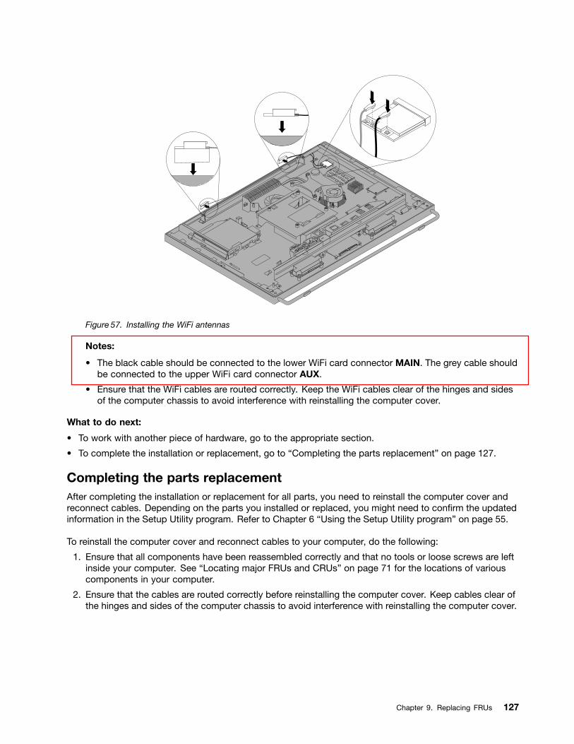
Figure 57. Installing the WiFi antennas
Notes:
The black cable should be connected to the lower WiFi card connector MAIN. The grey cable shouldbe connected to the upper WiFi card connector AUX.
Ensure that the WiFi cables are routed correctly. Keep the WiFi cables clear of the hinges and sidesof the computer chassis to avoid interference with reinstalling the computer cover.
What to do next:
To work with another piece of hardware, go to the appropriate section.
To complete the installation or replacement, go to Completing the parts replacement on page 127.
Completing the parts replacementAfter completing the installation or replacement for all parts, you need to reinstall the computer cover andreconnect cables. Depending on the parts you installed or replaced, you might need to con rm the updatedinformation in the Setup Utility program. Refer to Chapter 6 Using the Setup Utility program on page 55.
To reinstall the computer cover and reconnect cables to your computer, do the following:
1. Ensure that all components have been reassembled correctly and that no tools or loose screws are leftinside your computer. See Locating major FRUs and CRUs on page 71 for the locations of variouscomponents in your computer.
2. Ensure that the cables are routed correctly before reinstalling the computer cover. Keep cables clear ofthe hinges and sides of the computer chassis to avoid interference with reinstalling the computer cover.
Chapter 9. Replacing FRUs 127
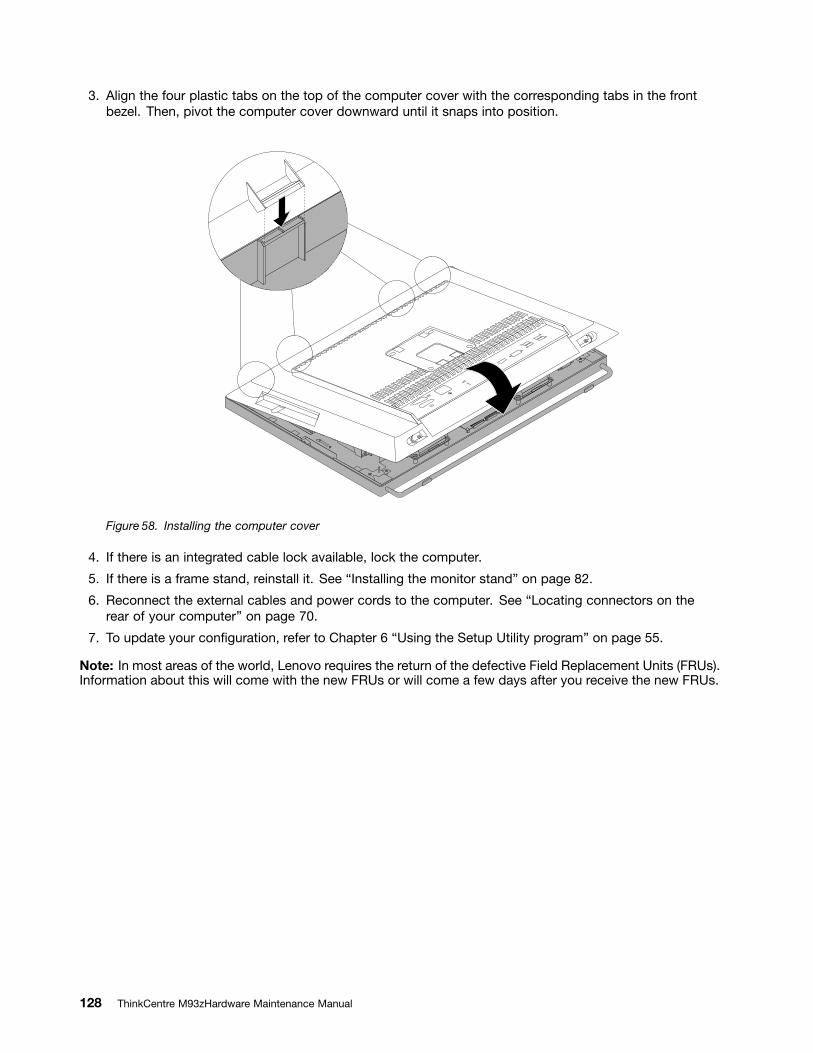
3. Align the four plastic tabs on the top of the computer cover with the corresponding tabs in the frontbezel. Then, pivot the computer cover downward until it snaps into position.
Figure 58. Installing the computer cover
4. If there is an integrated cable lock available, lock the computer.
5. If there is a frame stand, reinstall it. See Installing the monitor stand on page 82.
6. Reconnect the external cables and power cords to the computer. See Locating connectors on therear of your computer on page 70.
7. To update your con guration, refer to Chapter 6 Using the Setup Utility program on page 55.
Note: In most areas of the world, Lenovo requires the return of the defective Field Replacement Units (FRUs).Information about this will come with the new FRUs or will come a few days after you receive the new FRUs.
128 ThinkCentre M93zHardware Maintenance Manual
Chapter 10. Additional Service Information
This chapter provides additional information that the service representative might nd helpful.
Security featuresSecurity features in this section include the following:
Passwords
Vital Product Data
Management Information Format (MIF)
Hardware controlled PasswordsHardware controlled passwords are set using the Setup Utility program. For more information aboutpasswords, see Using passwords on page 55.
Operating system passwordAn operating system password is very similar to a power-on password and denies access to the computerby an unauthorized user when the password is activated. The computer is unusable until the password isentered and recognized by the computer.
Vital product dataEach computer has a unique Vital Product Data (VPD) code stored in the nonvolatile memory on the systemboard. After you replace the system board, the VPD must be updated. To update the VPD, see Flashupdate procedures on page 129.
BIOS levelsAn incorrect level of BIOS can cause false errors and unnecessary FRU replacement. Use the followinginformation to determine the current level of BIOS installed in the computer, the latest BIOS available for thecomputer, and where to obtain the latest level of BIOS.
To determine the current Level of BIOS:Start the Setup Utility.Select Main ᇆ BIOS Revision Level
Sources for obtaining the latest level BIOS available1. Lenovo support web site: http://www.lenovo.com/support/2. Lenovo Customer Support Center3. Levels 1 and 2 Support
To update ( ash) the BIOS, see Flash update procedures on page 129.
Note: BIOS settings vary by operating system. Change the BIOS settings before installing a new operatingsystem. See Changing the BIOS settings before installing a new operating system on page 60.
Flash update proceduresThis section details how to ash (update) the BIOS.
Copyright Lenovo 2013 129
Updating ( ashing) the BIOS from a discThis section provides instructions on how to update ( ash) the BIOS from a disc on the Windows 8 (64-bit)operating system and on other operating systems.
Note: You can download a self-starting bootable disc image (known as an ISO image) with the systemprogram updates to create a system-program-update disc. Go to http://www.lenovo.com/support.
To update ( ash) the BIOS from a disc on the Windows 8 (64-bit) operating system, do the following:
1. Start the Setup Utility program. See Starting the Setup Utility program on page 55.
2. From the Setup Utility program main menu, select Exit ᇆ OS Optimized Default ᇆ Disabled.
3. Select Yes in the window displayed and press Enter to con rm your selection.
4. Press F10 to save changes and exit the Setup Utility program. See Exiting the Setup Utility programon page 60.
5. Repeatedly press and release F12 when turning on the computer. When the Startup Device Menuwindow opens, release F12.
6. From the Startup Device Menu window, select the desired optical drive as the startup device. Then,insert the disc into this optical drive and press Enter. The update begins.
7. When prompted to change the serial number, it is suggested that you do not make this change bypressing N. However, if you do want to change the serial number, press Y, and then type in the serialnumber and press Enter.
8. When prompted to change the machine type and model, it is suggested that you do not make thischange by pressing N. However, if you do want to change the machine type and model, press Y, andthen type in the machine type and model and press Enter.
9. Follow the instructions on the screen to complete the update. After the update is completed, remove thedisc from the optical drive.
10. Restart your computer and start the Setup Utility program. See Starting the Setup Utility programon page 55.
11. From the Setup Utility program main menu, select Exit ᇆ OS Optimized Default ᇆ Enabled.
12. Select Yes in the window displayed and press Enter to con rm your selection.
13. Press F10 to save changes and exit the Setup Utility program. See Exiting the Setup Utility programon page 60.
To update ( ash) the BIOS from a disc on other operating systems, do the following:
1. Turn off your computer.
2. Repeatedly press and release F12 when turning on the computer. When the Startup Device Menuwindow opens, release F12.
3. From the Startup Device Menu window, select the desired optical drive as the startup device. Then,insert the disc into this optical drive and press Enter. The update begins.
4. When prompted to change the serial number, it is suggested that you do not make this change bypressing N. However, if you do want to change the serial number, press Y, and then type in the serialnumber and press Enter.
5. When prompted to change the machine type and model, it is suggested that you do not make thischange by pressing N. However, if you do want to change the machine type and model, press Y, andthen type in the machine type and model and press Enter.
6. Follow the instructions on the screen to complete the update. After the update is completed, remove thedisc from the optical drive.
130 ThinkCentre M93zHardware Maintenance Manual
Updating ( ashing) the BIOS from your operating systemNote: Because Lenovo makes constant improvements to its Web sites, the Web page contents are subjectto change without notice, including the contents referenced in the following procedure.
To update ( ash) the BIOS from your operating system, do the following:
1. Go to http://www.lenovo.com/support.
2. Click Download Drivers & Software.
3. Click Use Quick Path.
4. Type the 4-digit machine type for your computer in the Quick Path eld and then click Find My Product.
5. Click BIOS.
6. Locate the BIOS version that you want to download.
7. Click Click for les. All available les will be displayed.
8. Click the link for the readme le that contains the instructions for updating ( ashing) the BIOS fromyour operating system.
9. Print these instructions. This is very important because these instructions will not be displayed onthe screen after the download begins.
10. Follow the printed instructions to download, extract, and install the update.
Recovering from a POST/BIOS update failureIf the power to your computer is interrupted while the POST and BIOS is being updated, your computermight not restart correctly. If this happens, perform the following procedure to recover from the POST andBIOS update failure. This procedure is commonly called Boot-block Recovery.
1. Remove all media from the drives and turn off all attached devices and the computer. Then, disconnectall power cords from electrical outlets and disconnect all cables that are connected to the computer.
2. Remove the computer cover. See Removing the computer cover on page 84.
3. Locate the Clear CMOS /Recovery jumper on the system board. See Locating parts on the systemboard on page 74.
4. Remove any cables that impede access to the Clear CMOS /Recovery jumper.
5. Move the jumper from the standard position (pin 1 and pin 2) to the maintenance position (pin 2 andpin 3).
6. Reconnect any cables that were disconnected.
7. Reinstall the computer cover and connect the power cord. See Completing the parts replacement onpage 127.
8. Turn on the computer and then insert the POST and BIOS update ( ash update) disc into the opticaldrive. Wait a few minutes. Then, the recovery session begins. The recovery session will take two tothree minutes. During this time, a warning message will be displayed and no action is needed from you.
9. After the recovery session is completed, there will be no video, and your computer will automaticallyturn off.
10. Repeat step 1 through step 4.
11. Move the Clear CMOS /Recovery jumper back to the standard position (pin 1 and pin 2).
12. Reconnect any cables that were disconnected.
13. Reinstall the computer cover and reconnect any cables that were disconnected.
14. Turn on the computer to restart the operating system.
Chapter 10. Additional Service Information 131
Power managementPower management reduces the power consumption of certain components of the computer such as thesystem power supply, processor, hard disk drives, and display.
Automatic con guration and power interface (ACPI) BIOSBeing an ACPI BIOS system, the operating system is allowed to control the power management featuresof the computer and the setting for Advanced Power Management (APM) BIOS mode is ignored. Notall operating systems support ACPI BIOS mode.
Automatic Power-on featuresThe Automatic Power-On features within the Power Management menu allow you to enable and disablefeatures that turn on the computer automatically.
Wake Up on Alarm: You can specify a date and time at which the computer will be turned onautomatically. This can be either a single event or a daily event.
Wake on LAN: If the computer has a properly con gured token-ring or Ethernet LAN adapter card that isWake on LAN-enabled and there is remote network management software, you can use the Wake on LANfeature. When you set Wake on LAN to Enabled, the computer will turn on when it receives a speci csignal from another computer on the local area network (LAN).
To enable the Wake on LAN function or the Wake Up on Alarm function on the Windows 8 operating system,do the following:
1. Open Control Panel.
2. Click Hardware and Sound ᇆ Power Options.
3. In the left panel, click Choose what the power buttons do.
4. In the Shutdown setting section, clear Turn on fast startup.
Note: If the settings are unavailable, click Change settings that are currently unavailable.
5. Click Save changes.
132 ThinkCentre M93zHardware Maintenance Manual
Appendix A. Notices
Lenovo may not offer the products, services, or features discussed in this document in all countries. Consultyour local Lenovo representative for information on the products and services currently available in yourarea. Any reference to a Lenovo product, program, or service is not intended to state or imply that only thatLenovo product, program, or service may be used. Any functionally equivalent product, program, or servicethat does not infringe any Lenovo intellectual property right may be used instead. However, it is the user'sresponsibility to evaluate and verify the operation of any other product, program, or service.
Lenovo may have patents or pending patent applications covering subject matter described in thisdocument. The furnishing of this document does not give you any license to these patents. You can sendlicense inquiries, in writing, to:
Lenovo (United States), Inc.1009 Think Place - Building OneMorrisville, NC 27560U.S.A.Attention: Lenovo Director of Licensing
LENOVO PROVIDES THIS PUBLICATION AS IS WITHOUT WARRANTY OF ANY KIND, EITHER EXPRESSOR IMPLIED, INCLUDING, BUT NOT LIMITED TO, THE IMPLIED WARRANTIES OF NON-INFRINGEMENT,MERCHANTABILITY OR FITNESS FOR A PARTICULAR PURPOSE. Some jurisdictions do not allowdisclaimer of express or implied warranties in certain transactions, therefore, this statement may not applyto you.
This information could include technical inaccuracies or typographical errors. Changes are periodicallymade to the information herein; these changes will be incorporated in new editions of the publication.Lenovo may make improvements and/or changes in the product(s) and/or the program(s) described in thispublication at any time without notice.
The products described in this document are not intended for use in implantation or other life supportapplications where malfunction may result in injury or death to persons. The information contained in thisdocument does not affect or change Lenovo product speci cations or warranties. Nothing in this documentshall operate as an express or implied license or indemnity under the intellectual property rights of Lenovoor third parties. All information contained in this document was obtained in speci c environments and ispresented as an illustration. The result obtained in other operating environments may vary.
Lenovo may use or distribute any of the information you supply in any way it believes appropriate withoutincurring any obligation to you.
Any references in this publication to non-Lenovo Web sites are provided for convenience only and do not inany manner serve as an endorsement of those Web sites. The materials at those Web sites are not part ofthe materials for this Lenovo product, and use of those Web sites is at your own risk.
Any performance data contained herein was determined in a controlled environment. Therefore, the resultobtained in other operating environments may vary signi cantly. Some measurements may have beenmade on development-level systems and there is no guarantee that these measurements will be the sameon generally available systems. Furthermore, some measurements may have been estimated throughextrapolation. Actual results may vary. Users of this document should verify the applicable data for theirspeci c environment.
Copyright Lenovo 2013 133

Television output noticeThe following notice applies to models that have the factory-installed television-output feature.
This product incorporates copyright protection technology that is protected by method claims of certain U.S.patents and other intellectual property rights owned by Macrovision Corporation and other rights owners.Use of this copyright protection technology must be authorized by Macrovision Corporation, and is intendedfor home and other limited viewing uses only unless otherwise authorized by Macrovision Corporation.Reverse engineering or disassembly is prohibited.
European conformance CE mark
TrademarksThe following terms are trademarks of Lenovo in the United States, other countries, or both:
LenovoThe Lenovo logoRescue and RecoveryThinkCentreThinkVantage
Microsoft, Windows, and Windows Vista are trademarks of the Microsoft group of companies.
Other company, product, or service names may be trademarks or service marks of others.
134 ThinkCentre M93zHardware Maintenance Manual
Index
AAdministrator, password 56ambient light sensor, replacing 106
Bbasic troubleshooting 35battery, replacing 114BIOS settings, changing 60boot-block recovery 131
Ccard reader, replacing 107changing
password 56startup device sequence 58
cleaning an optical mouse 43CMOS, clearing 57components, internal 71computer cover
removing 84computer cover, reinstalling 127connectors
rear 70connectors, controls, indicators
front 67considerations, passwords 56converter board, replacing 91cover presence switch, replacing 100CRUs (Customer Replacable Units), returning defective 71
Ddeleting a password 56devices, handling static-sensitive 81diagnostics, troubleshooting 35
Eenvironment, operating 30exiting, Setup Utility 60ExpressCard, replacing 110external options, installing 81
Ffailure, recovering from POST/BIOS 131ashing the BIOS 130
frame footremoving 85
frontconnectors, controls, indicators 67
FRU
completing the installation 127FRU locations 71FRU part numbers 1, 67, 74FRUs, replacing 81
GGPU heat sin and fan, replacing 111
Hhard disk drive, replacing 88heat sink, replacing 92
IIdentifying FRUs 71installing
operating system 60installing options
memory module 87integrated camera, replacing 103internal speakers, replacing 97
LLenovo Solution Center 53locating components 71looking up part numbers 1, 67, 74
Mmemory module
installing, replacing 87system board 87
microprocessorreplacing 94
monitor standremoving 82
mSATA solid-state drive, mini PCI Express x1 card,replacing 108
Nnotice, television output 134notices 133
Ooptical drive, replacing 90optical mouse
cleaning 43Optional-service CRUs 71
Copyright Lenovo 2013 135
Ppart numbers 1, 67, 74parts replacement, completing 127password
Administrator 56considerations 56Power-On Password 56setting, changing, deleting 56
passwordserasing 57lost or forgotten 57
passwords, using 55physical speci cations 29Power-On, Password 56
Rrear connectors 70rear I/O assembly
removing 86rear PS/2 connectors and serial port assembly
removing 113recovering
from a POST/BIOS update failure 131recovery
boot-block 131removing computer cover 84removing frame foot 85removing monitor stand 82removing rear I/O assembly 86removing rear PS/2 connectors and serial port assembly 113replacing
ambient light sensor 106battery 114card reader 107converter board 91cover presence switch 100ExpressCard 110GPU heat sink and fan 111hard disk drive 88heat sink 92integrated camera 103internal speakers 97microprocessor 94mSATA solid-state drive, mini PCI Express x1 card 108system board 120thermal sensor 98WiFi antenna 125WiFi card 105
replacing the LCD panel 119replacing the microprocessor fan 117replacing the power supply assembly 116replacing the power switch and control button board 124replacing the touch panel control boards 123
Ssecurity
enabling or disabling 57
selectingstartup device 58temporary startup device 58
Self-service CRUs 71setting
password 56settings
changing 55viewing 55
Setup Utility 55Setup Utility program, starting 55Setup Utility, exiting 60starting the Setup Utility program 55startup device 58
sequence, changing 58temporary, selecting 58
static-sensitive devices, handling 81support web site
support 31support, web site 31system board
connectors 74locating parts 74locations 74memory module 87
system board, replacing 120
Ttelevision output notice 134temporary startup device 58the BIOS, updating ( ashing) 130 131the LCD panel
replacing 119the microprocessor fan
replacing 117the power supply assembly
replacing 116the power switch and control button board
replacing 124the touch panel control boards
replacing 123thermal sensor, replacing 98trademarks 134troubleshooting, basic 35troubleshooting, diagnostics 35
Uupdating
( ashing) the BIOS 130updating ( ashing) the BIOS 131using
passwords 55Setup Utility 55
Vviewing and changing settings 55
136 ThinkCentre M93zHardware Maintenance Manual

WWiFi antenna, replacing 125WiFi card, replacing 105
Copyright Lenovo 2013 137

138 ThinkCentre M93zHardware Maintenance Manual


![Faurecia Group Presentation July 2016_VA 4 3 FINAL[4982]](https://img.pdfslide.us/doc/110x75/5899be8e1a28aba11e8b7bed/faurecia-group-presentation-july-2016va-4-3-final4982.jpg)