Embed Size (px)
Citation preview
Chapter 6
More on geometrical optics
Thick lensesAnalytical ray tracingAberrations
Phys 322Lecture 17
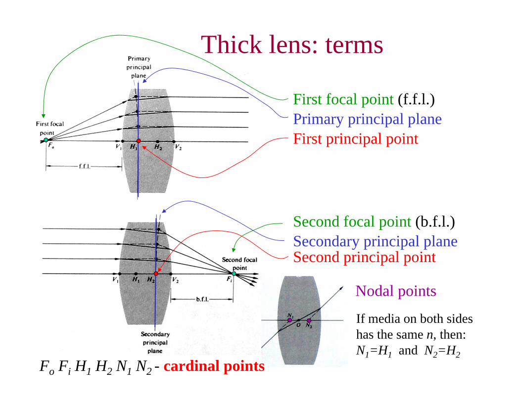
First focal point (f.f.l.)
Second focal point (b.f.l.)
Primary principal plane
Secondary principal plane
First principal point
Second principal point
Thick lens: terms
Nodal points
If media on both sides has the same n, then:N1=H1 and N2=H2
Fo Fi H1 H2 N1 N2 - cardinal points
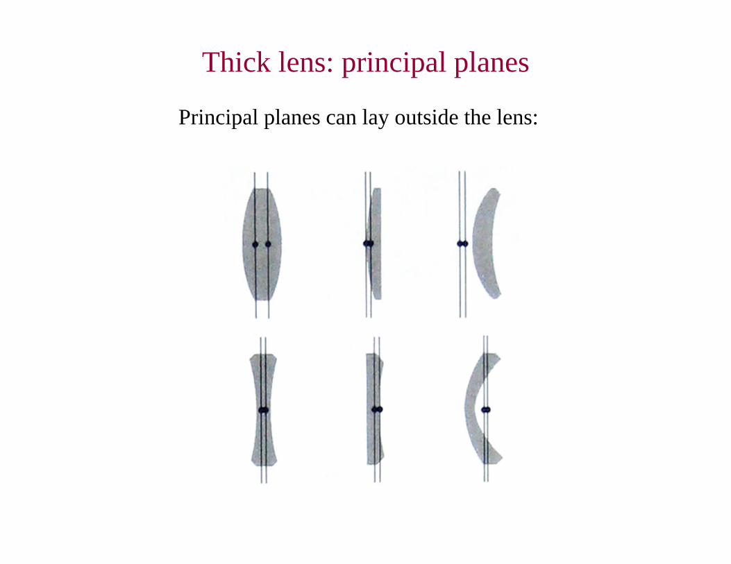
Thick lens: principal planes
Principal planes can lay outside the lens:
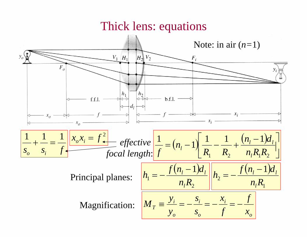
Thick lens: equations
fss io
111
Note: in air (n=1)
2fxx io effective focal length:
2121
11111RRn
dnRR
nf l
lll
2
11
Rndnfh
l
ll
12
1Rn
dnfhl
ll Principal planes:
o
i
o
i
o
iT x
ffx
ss
yyM Magnification:
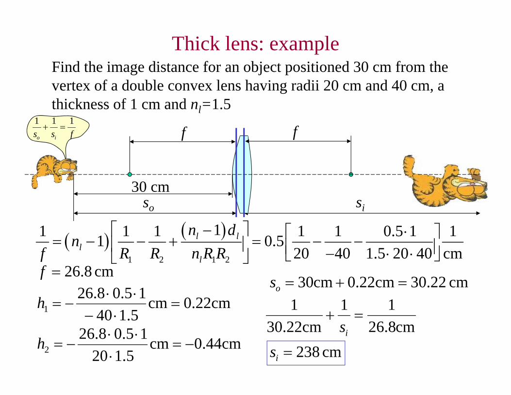
Thick lens: exampleFind the image distance for an object positioned 30 cm from the vertex of a double convex lens having radii 20 cm and 40 cm, a thickness of 1 cm and nl=1.5
cm 30.22cm22.0cm30 os
so si
30 cm
fss io
111
1 2 1 2
11 1 1 1 1 0.5 1 11 0.520 40 1.5 20 40 cm
l ll
l
n dn
f R R n R R
cm 8.26f
cm22.0cm5.14015.08.26
1
h
f
cm44.0cm5.120
15.08.262
h
f
cm8.2611
cm22.301
is
cm 238is
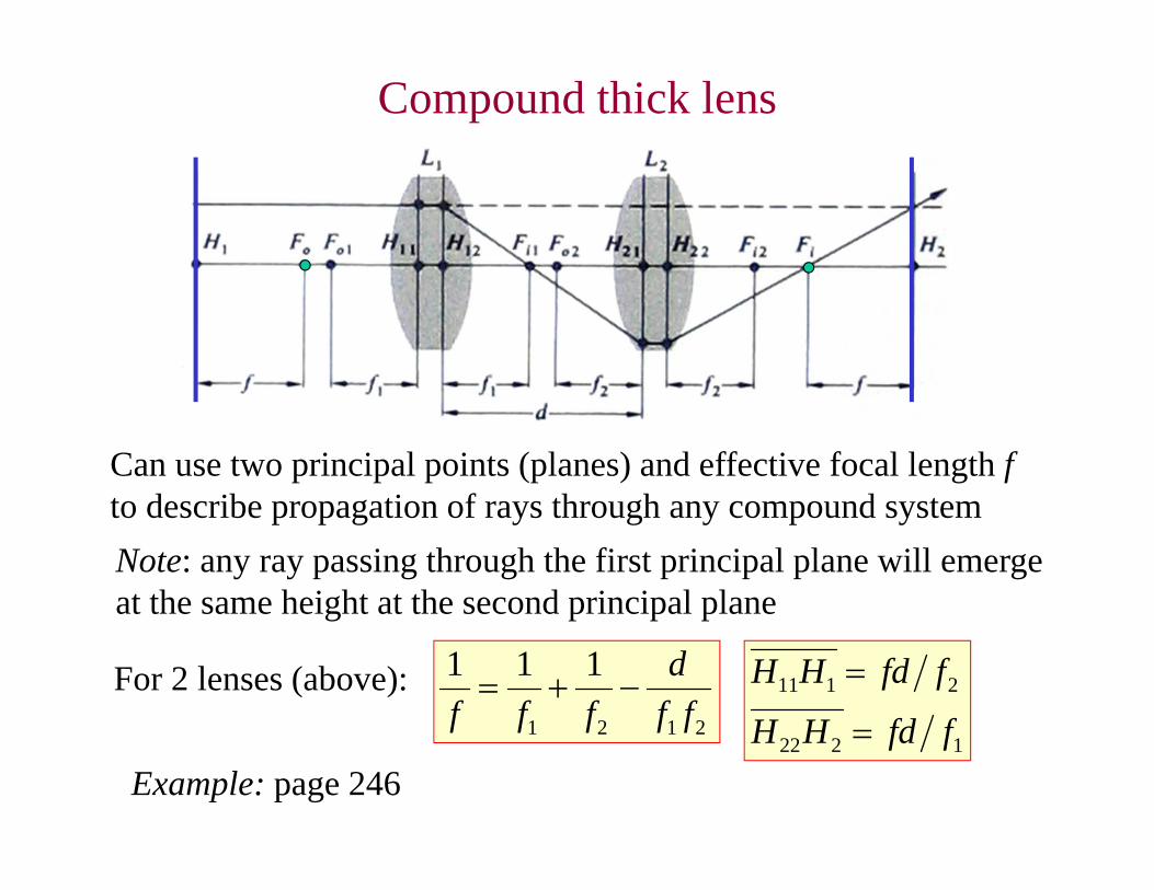
Compound thick lens
Can use two principal points (planes) and effective focal length fto describe propagation of rays through any compound systemNote: any ray passing through the first principal plane will emerge at the same height at the second principal plane
For 2 lenses (above):2121
111ff
dfff
1222
2111
ffdHH
ffdHH
Example: page 246
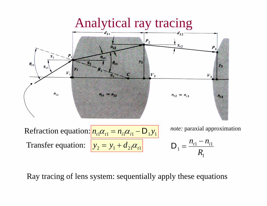
Analytical ray tracing
Refraction equation: 111111 ynn iitt D
Transfer equation: 12112 tdyy
note: paraxial approximation
Ray tracing of lens system: sequentially apply these equations
1
111 R
nn it D
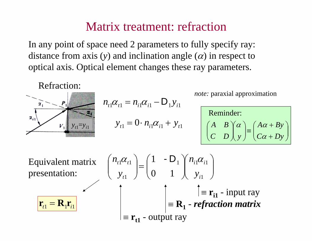
Matrix treatment: refraction
note: paraxial approximation
In any point of space need 2 parameters to fully specify ray:distance from axis (y) and inclination angle () in respect to optical axis. Optical element changes these ray parameters.
111111 iiitt ynn D
1111 0 tiit yny
Refraction:
yt1=yi1
1
111
1
11
101
i
ii
t
tt
yn
yn D-Equivalent matrix
presentation:
Reminder:
DyCByA
yDCBA
rt1 - output ray
ri1 - input ray R1 - refraction matrix111 it rRr
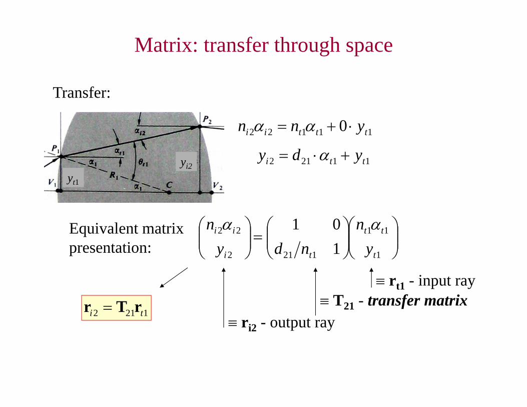
Matrix: transfer through space
11122 0 tttii ynn
11212 tti ydy
1
11
1212
22
101
t
tt
ti
ii
yn
ndyn Equivalent matrix
presentation:
ri2 - output ray
rt1 - input ray T21 - transfer matrix
1212 ti rTr
Transfer:
yt1
yi2
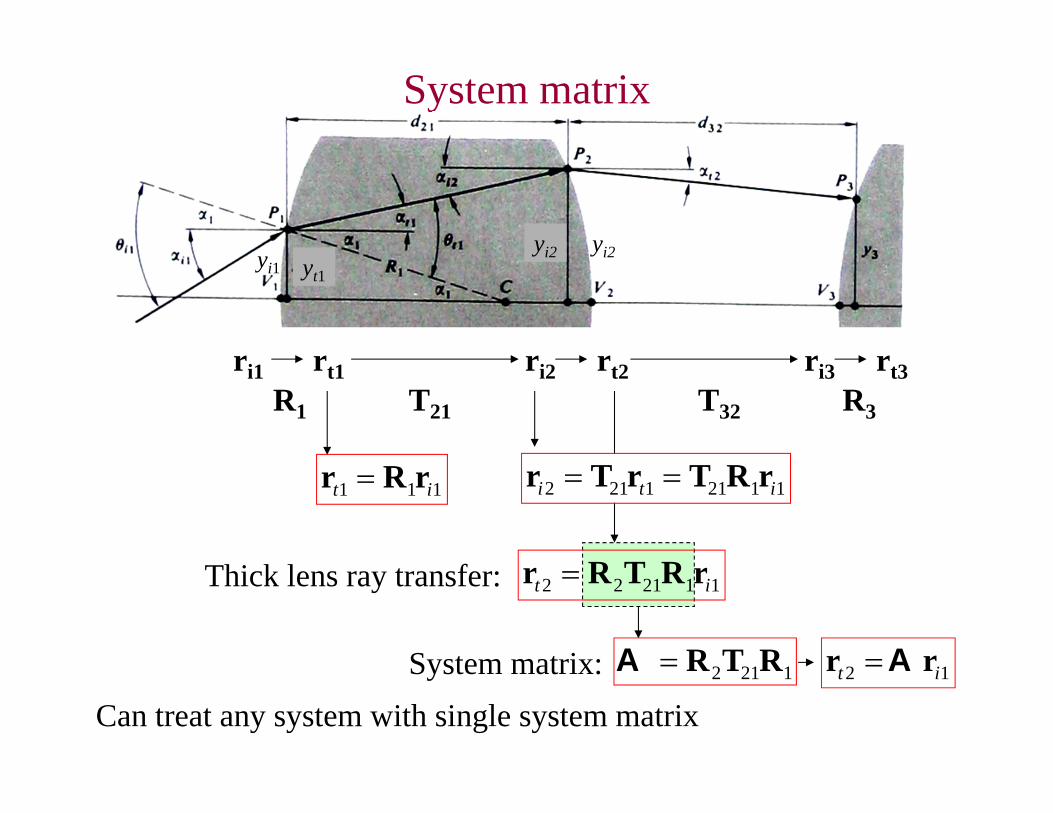
112122 it rRTRr
System matrix
yt1yi1
yi2 yi2
ri1 rt1 ri2 rt2R1 T21
ri3 rt3R3T32
111 it rRr 11211212 iti rRTrTr
Thick lens ray transfer:
1212 RTRASystem matrix: 12 it rr ACan treat any system with single system matrix
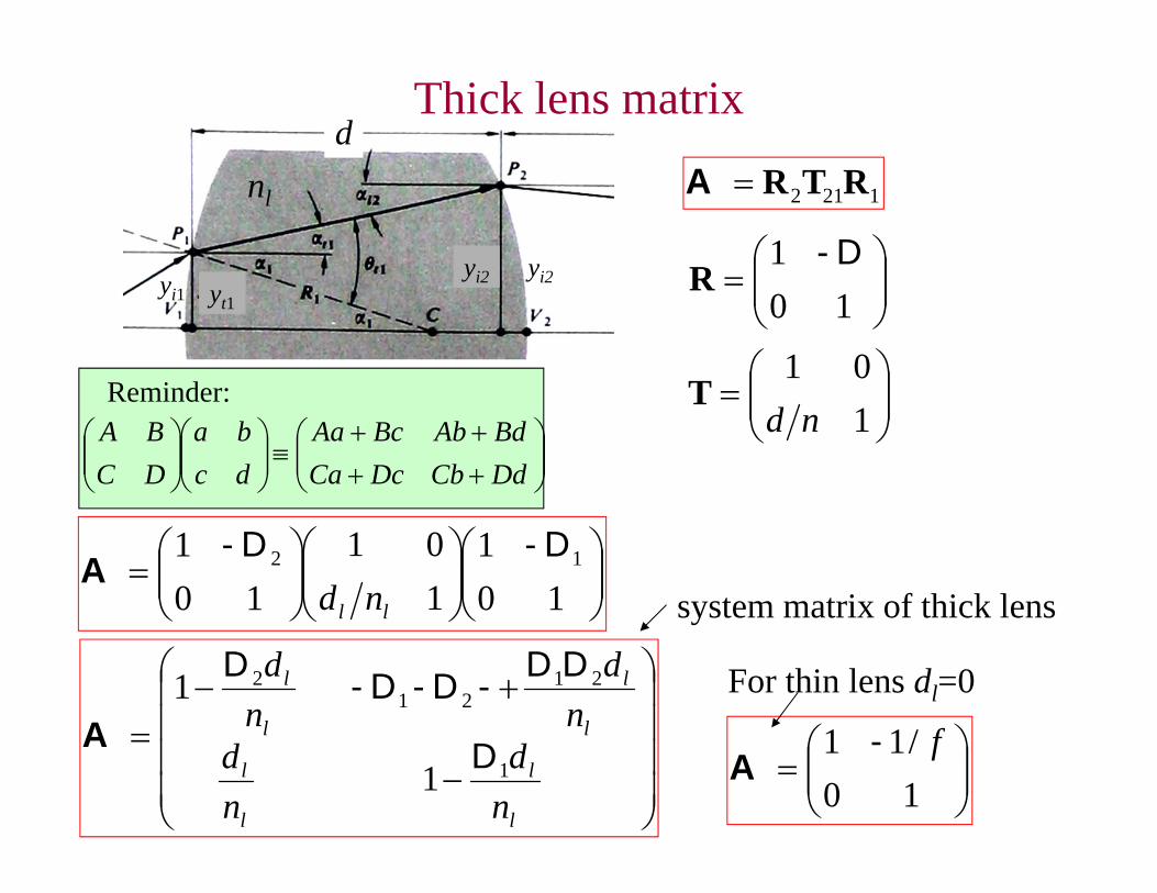
1212 RTRA
101 D-
R
101
ndTReminder:
DdCbDcCaBdAbBcAa
dcba
DCBA
101
101
101 12 D-D-
ll ndA
yt1yi1
yi2 yi2
nl
dThick lens matrix
l
l
l
l
l
l
l
l
nd
nd
nd
nd
1
2121
2
1
1
D
DD-D-D- D
A
system matrix of thick lens
For thin lens dl=0
10/11 f-
A
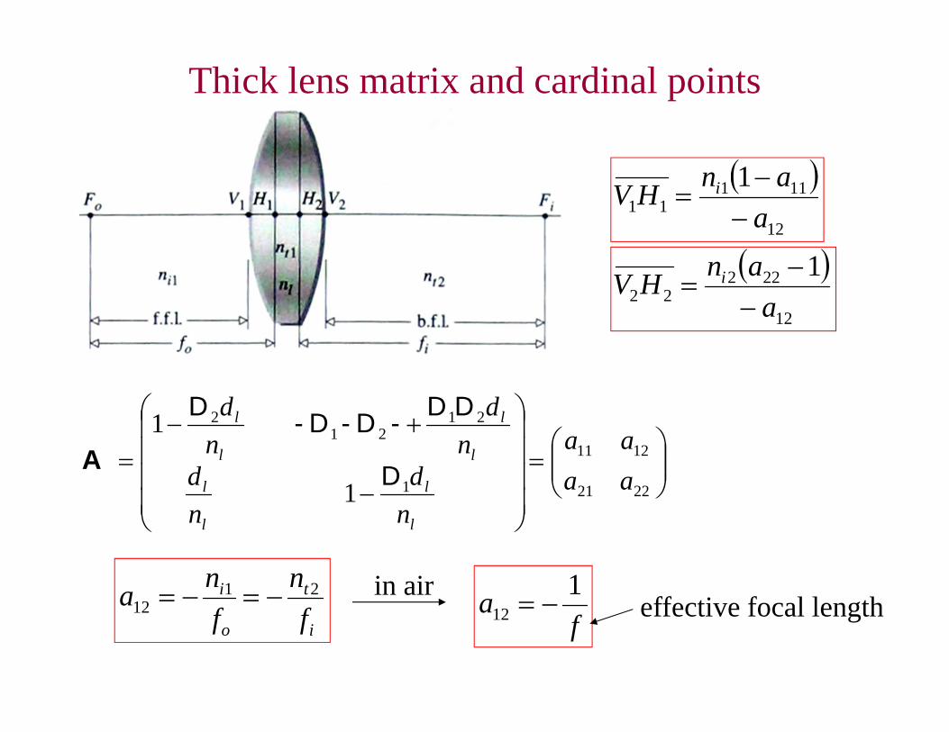
Thick lens matrix and cardinal points
2221
1211
1
2121
2
1
1
aaaa
nd
nd
nd
nd
l
l
l
l
l
l
l
l
D
DD-D-D-D
A
i
t
o
i
fn
fna 21
12 in airf
a 112 effective focal length
12
11111
1a
anHV i
12
22222
1a
anHV i
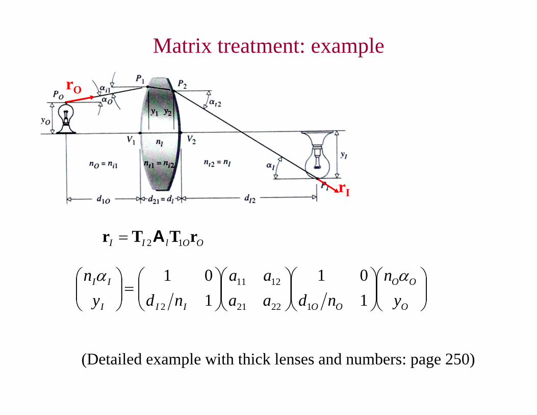
Matrix treatment: example
rO
rI
OOlII rTTr 12A
O
OO
OOIII
II
yn
ndaaaa
ndyn
101
101
12221
1211
2
(Detailed example with thick lenses and numbers: page 250)
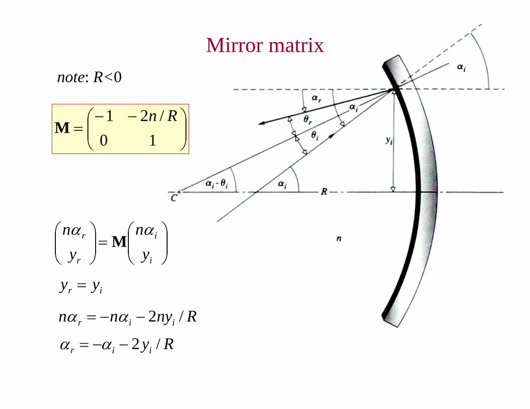
10/21 Rn
M
Mirror matrix
i
i
r
r
yn
yn
M
ir yy
Rnynn iir /2
note: R<0
Ryiir /2
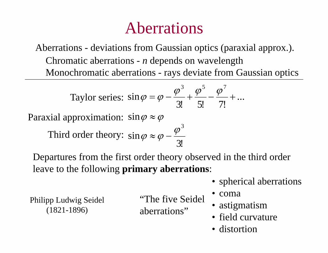
AberrationsAberrations - deviations from Gaussian optics (paraxial approx.).
Chromatic aberrations - n depends on wavelengthMonochromatic aberrations - rays deviate from Gaussian optics
• spherical aberrations• coma• astigmatism• field curvature• distortion
Paraxial approximation: sin
Third order theory:!3
sin3
Departures from the first order theory observed in the third order leave to the following primary aberrations:
Taylor series: ...!7!5!3
sin753
“The five Seidel aberrations”
Philipp Ludwig Seidel(1821-1896)
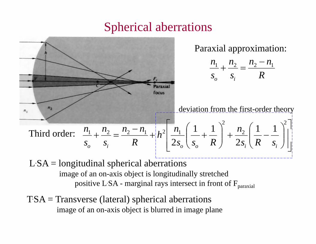
Spherical aberrationsParaxial approximation:
Rnn
sn
sn
io
1221
Third order:
2
2
2
121221 112
112 iiooio sRs
nRss
nhR
nnsn
sn
deviation from the first-order theory
L.SA = longitudinal spherical aberrationsimage of an on-axis object is longitudinally stretched
T.SA = Transverse (lateral) spherical aberrationsimage of an on-axis object is blurred in image plane
positive L.SA - marginal rays intersect in front of Fparaxial
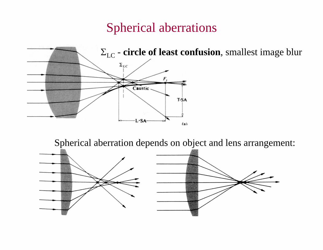
Spherical aberrations
LC - circle of least confusion, smallest image blur
Spherical aberration depends on object and lens arrangement:
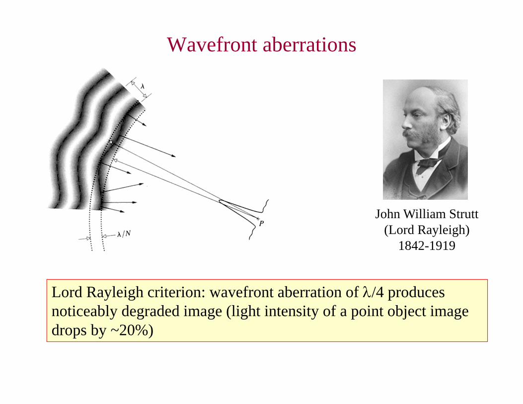
Wavefront aberrations
John William Strutt(Lord Rayleigh)
1842-1919
Lord Rayleigh criterion: wavefront aberration of /4 produces noticeably degraded image (light intensity of a point object image drops by ~20%)
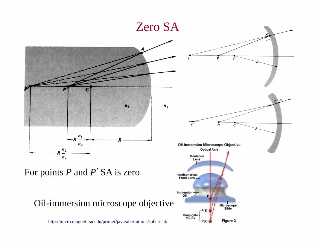
Zero SA
For points P and P’ SA is zero
Oil-immersion microscope objective
http://micro.magnet.fsu.edu/primer/java/aberrations/spherical/
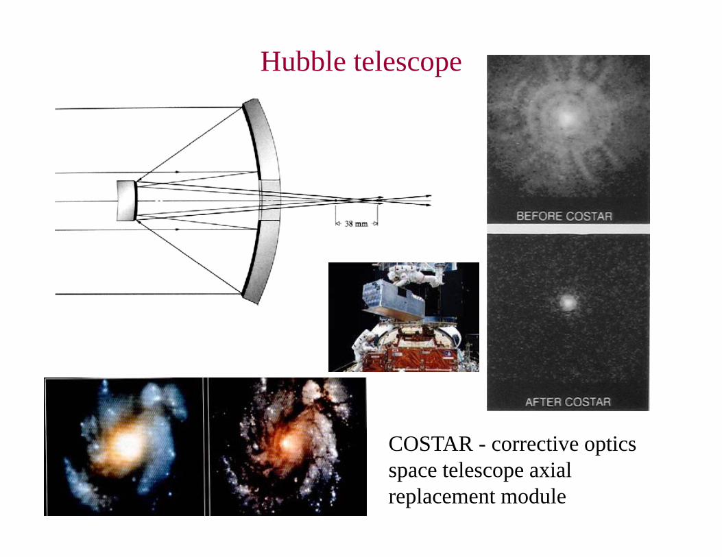
Hubble telescope
COSTAR - corrective optics space telescope axial replacement module
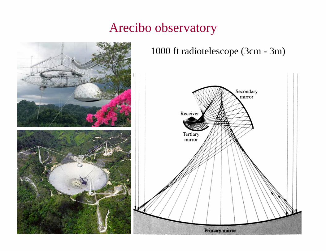
Arecibo observatory
1000 ft radiotelescope (3cm - 3m)
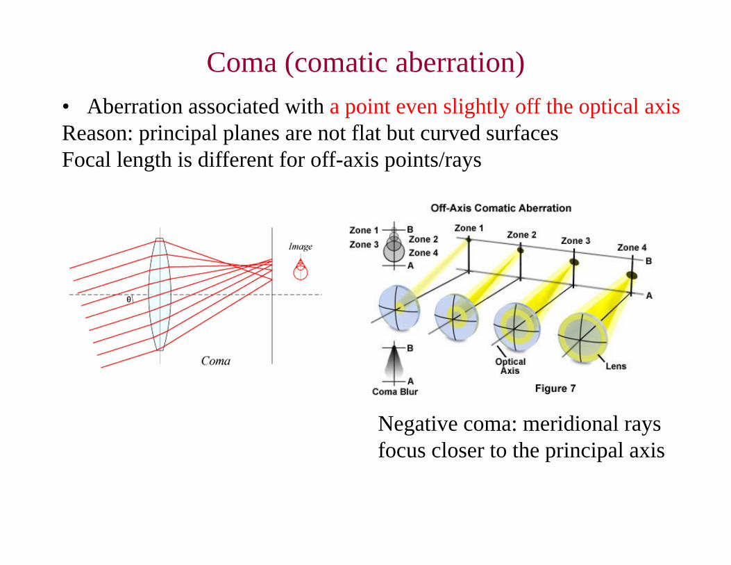
Coma (comatic aberration)• Aberration associated with a point even slightly off the optical axisReason: principal planes are not flat but curved surfacesFocal length is different for off-axis points/rays
Negative coma: meridional rays focus closer to the principal axis
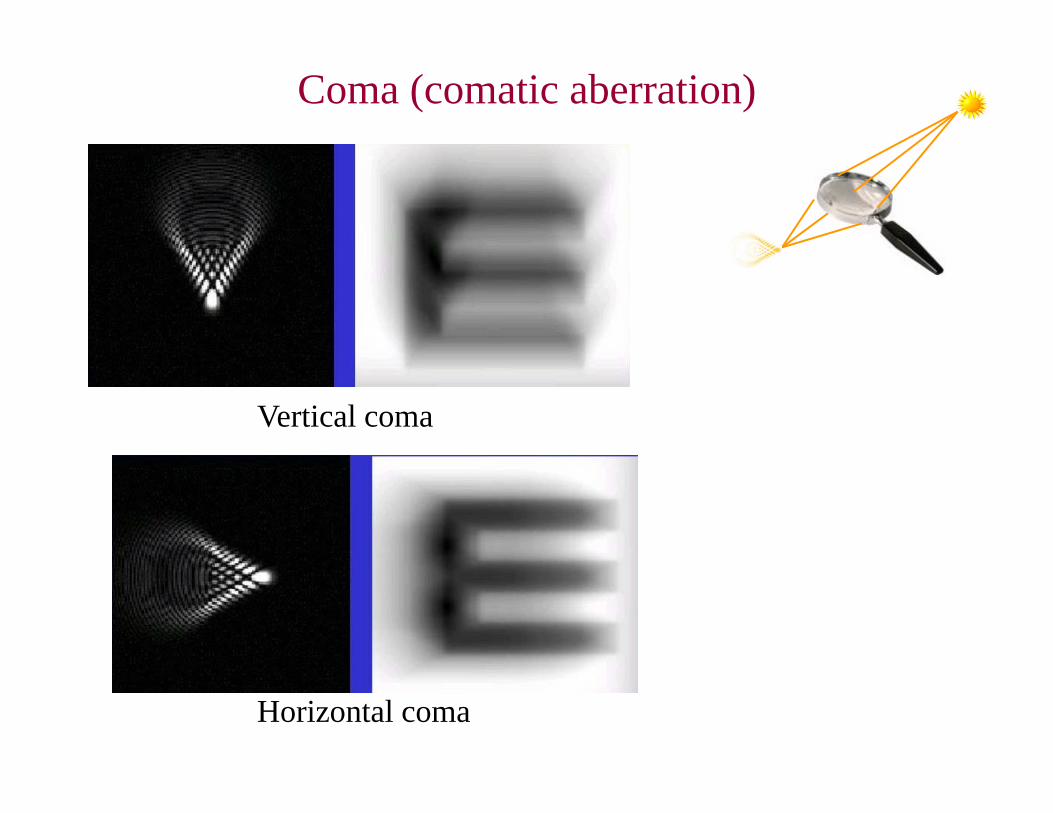
Coma (comatic aberration)
Vertical coma
Horizontal coma
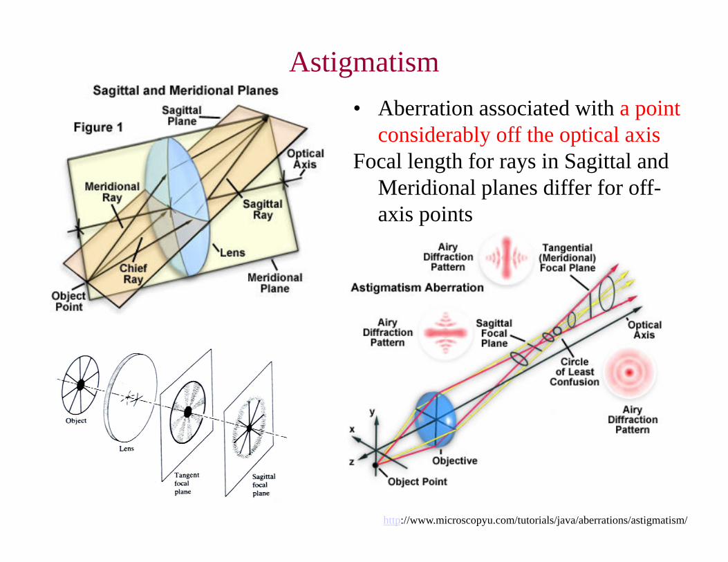
Astigmatism
http://www.microscopyu.com/tutorials/java/aberrations/astigmatism/
• Aberration associated with a point considerably off the optical axis
Focal length for rays in Sagittal and Meridional planes differ for off-axis points
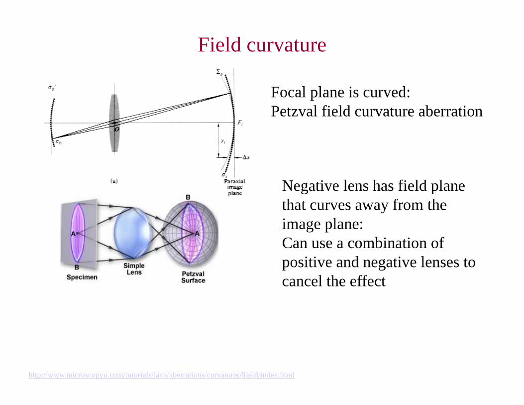
Field curvature
Focal plane is curved:Petzval field curvature aberration
http://www.microscopyu.com/tutorials/java/aberrations/curvatureoffield/index.html
Negative lens has field plane that curves away from the image plane:Can use a combination of positive and negative lenses to cancel the effect
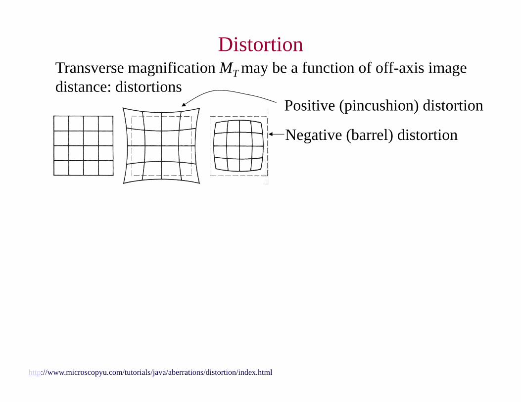
DistortionTransverse magnification MT may be a function of off-axis image distance: distortions
http://www.microscopyu.com/tutorials/java/aberrations/distortion/index.html
Positive (pincushion) distortion
Negative (barrel) distortion
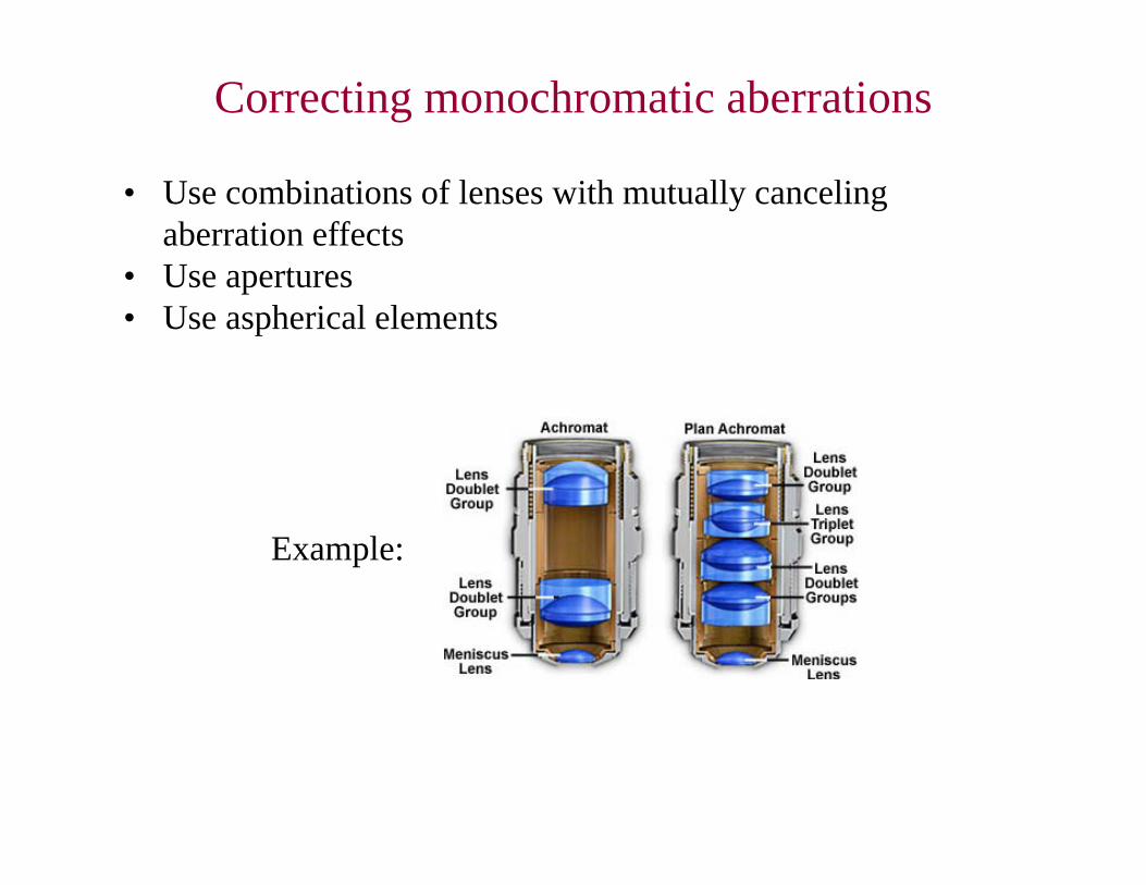
Correcting monochromatic aberrations
• Use combinations of lenses with mutually canceling aberration effects
• Use apertures• Use aspherical elements
Example:
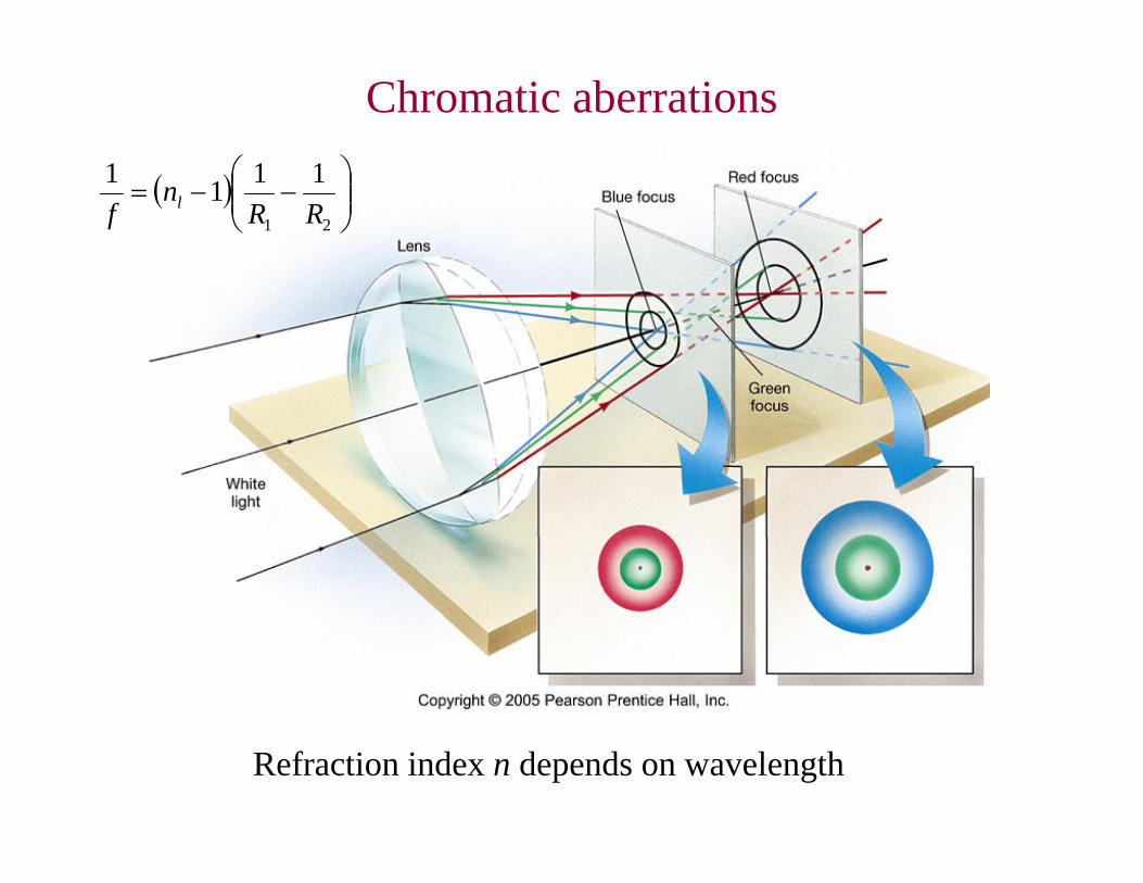
Chromatic aberrations
Refraction index n depends on wavelength
21
1111RR
nf l
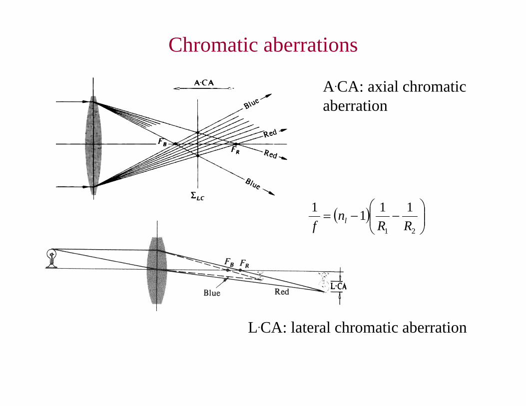
Chromatic aberrations
A.CA: axial chromatic aberration
L.CA: lateral chromatic aberration
21
1111RR
nf l
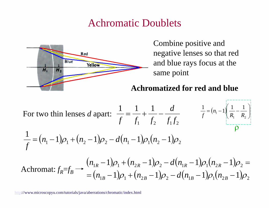
Achromatic Doublets
http://www.microscopyu.com/tutorials/java/aberrations/chromatic/index.html
Combine positive and negative lenses so that red and blue rays focus at the same point
Achromatized for red and blue
For two thin lenses d apart:2121
111ff
dfff
21
1111RR
nf l
22112211 11111 nndnn
f
Achromat: fR=fB
22112211
22112211
11111111
BBBB
RRRR
nndnnnndnn
Achromatic Doublets 22112211
22112211
11111111
BBBB
RRRR
nndnnnndnn
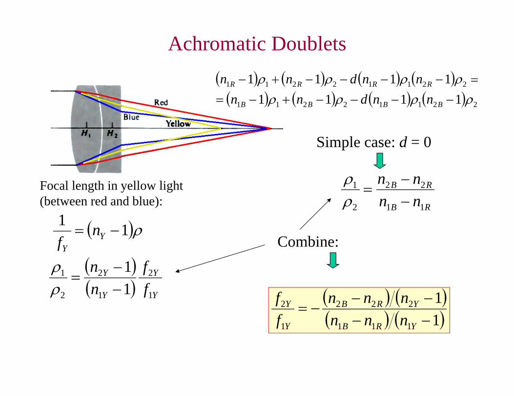
Simple case: d = 0
RB
RB
nnnn
11
22
2
1
Focal length in yellow light
(between red and blue):
11 Y
Y
nf
Y
Y
Y
Y
ff
nn
1
2
1
2
2
1
11
1
1
111
222
1
2
YRB
YRB
Y
Y
nnnnnn
ff
Combine:
Achromatic Doublets
http://www.microscopyu.com/tutorials/java/aberrations/chromatic/index.html
1
1
111
222
1
2
YRB
YRB
Y
Y
nnnnnn
ff
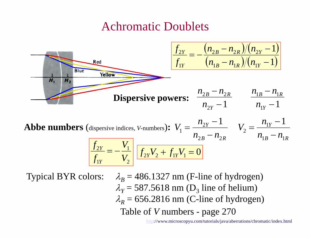
12
22
Y
RB
nnn
Dispersive powers: 11
11
Y
RB
nnn
Abbe numbers (dispersive indices, V-numbers):RB
Y
nnnV
22
21
1
RB
Y
nnnV
11
12
1
2
1
1
2
VV
ff
Y
Y 01122 VfVf YY
Typical BYR colors: B = 486.1327 nm (F-line of hydrogen)Y = 587.5618 nm (D3 line of helium)R = 656.2816 nm (C-line of hydrogen)Table of V numbers - page 270
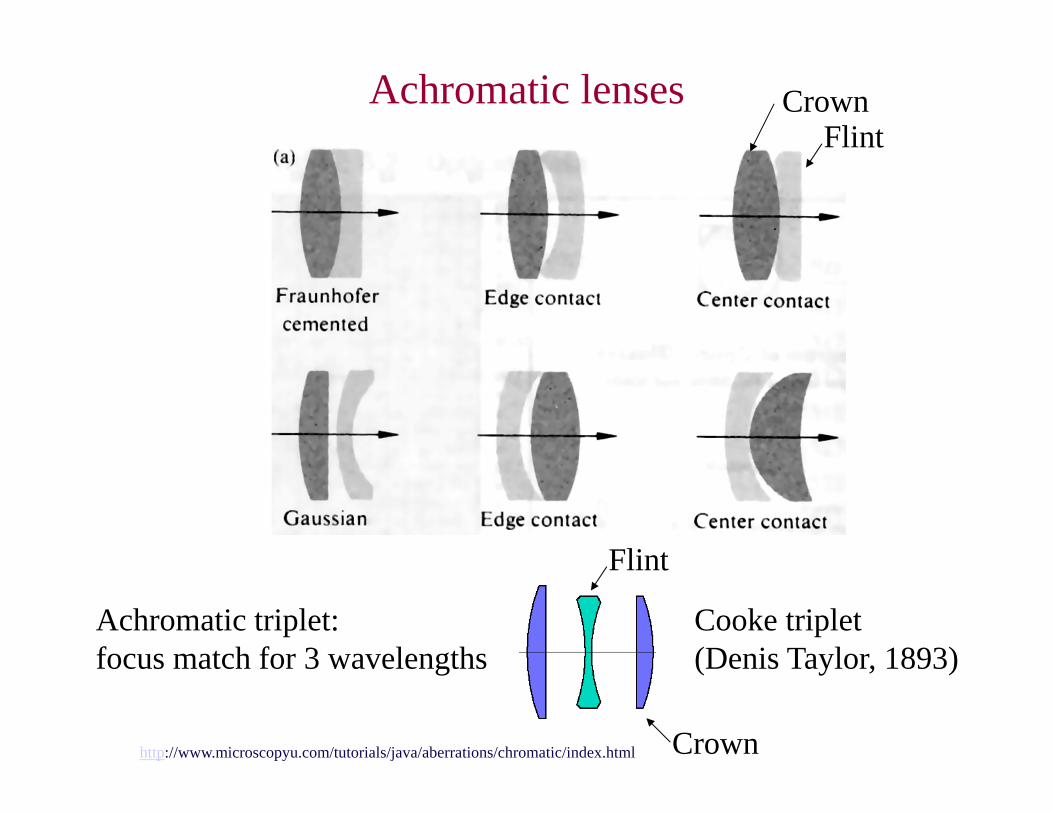
Achromatic lenses CrownFlint
http://www.microscopyu.com/tutorials/java/aberrations/chromatic/index.html
Achromatic triplet:focus match for 3 wavelengths
Cooke triplet(Denis Taylor, 1893)
Flint
Crown
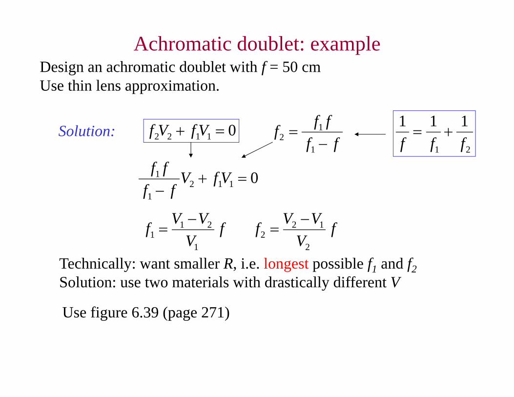
Achromatic doublet: exampleDesign an achromatic doublet with f = 50 cm Use thin lens approximation.
Solution:21
111fff
01122 VfVfff
fff
1
12
01121
1
VfVff
ff
fV
VVf1
211
f
VVVf
2
122
Technically: want smaller R, i.e. longest possible f1 and f2Solution: use two materials with drastically different V
Use figure 6.39 (page 271)
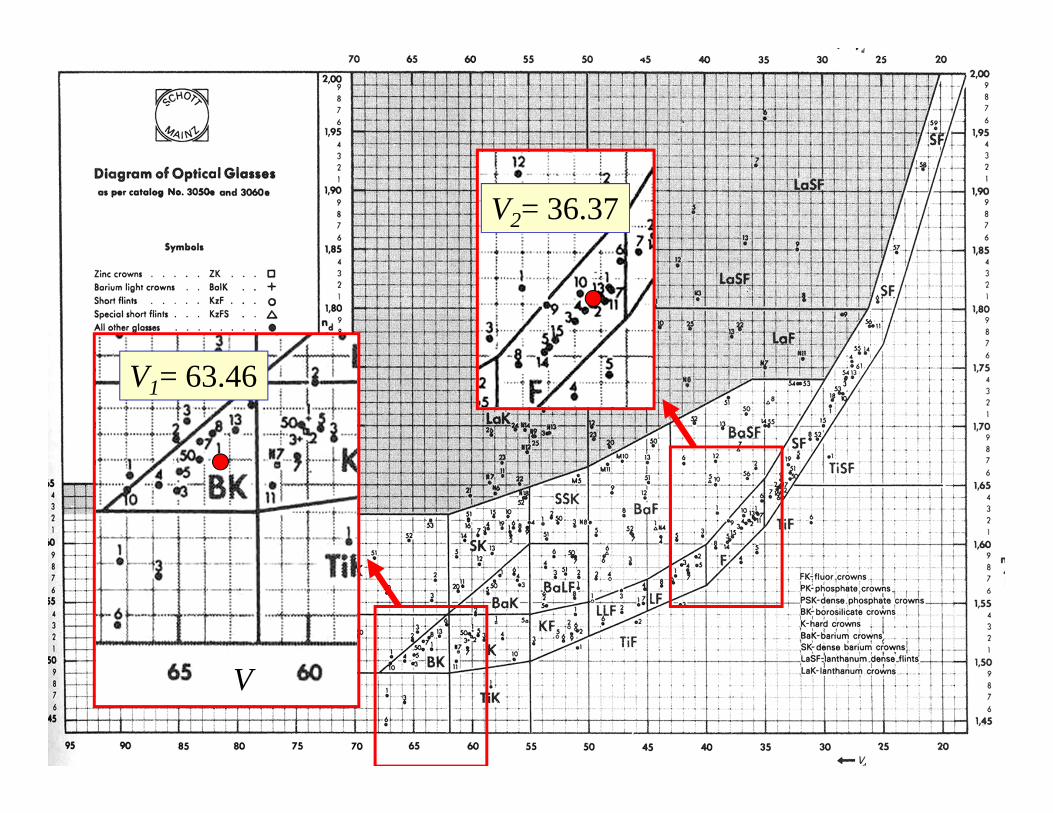
Achromatic doublet: example
V
V1= 63.46
V2= 36.37
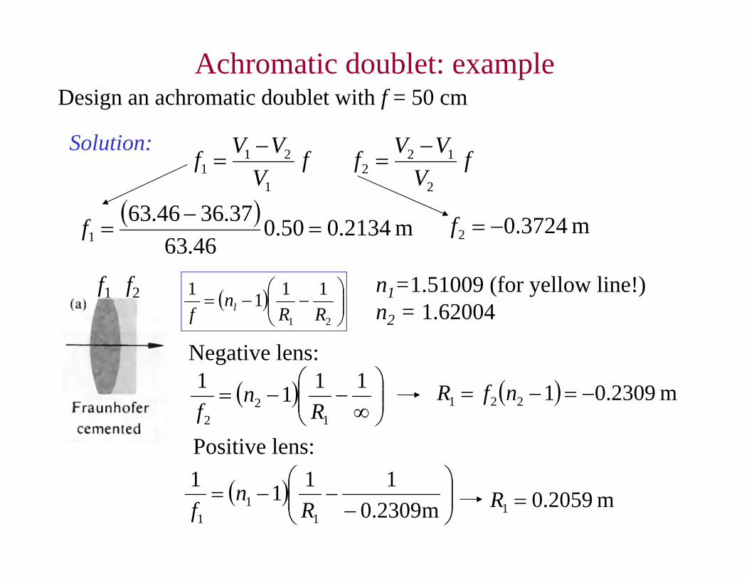
Achromatic doublet: exampleDesign an achromatic doublet with f = 50 cm
Solution:f
VVVf
1
211
f
VVVf
2
122
m 2134.050.046.63
37.3646.631
f m 3724.02 f
21
1111RR
nf l
f1 f2 n1=1.51009 (for yellow line!)n2 = 1.62004
Negative lens:
1111
12
2 Rn
f m 2309.01221 nfR
Positive lens:
m2309.0
1111
11
1 Rn
f m 2059.01 R


![Corneal Wavefront Aberrations in Patients Wearing ...concentric multifocal center-distance contact lenses [23- 25]. Orthokeratology, unlike unifocal spectacle lenses and contact lenses,](https://img.pdfslide.us/doc/110x75/5f4f5f12a0837a551d15d105/corneal-wavefront-aberrations-in-patients-wearing-concentric-multifocal-center-distance.jpg)