Embed Size (px)
Citation preview
HAL Id: hal-01716113https://hal.archives-ouvertes.fr/hal-01716113
Submitted on 11 Jan 2019
HAL is a multi-disciplinary open accessarchive for the deposit and dissemination of sci-entific research documents, whether they are pub-lished or not. The documents may come fromteaching and research institutions in France orabroad, or from public or private research centers.
L’archive ouverte pluridisciplinaire HAL, estdestinée au dépôt et à la diffusion de documentsscientifiques de niveau recherche, publiés ou non,émanant des établissements d’enseignement et derecherche français ou étrangers, des laboratoirespublics ou privés.
Thermomechanical stress analysis of superplasticforming tool
Cy Gao, Philippe Lours, Gérard Bernhart
To cite this version:Cy Gao, Philippe Lours, Gérard Bernhart. Thermomechanical stress analysis of superplasticforming tool. Journal of Materials Processing Technology, Elsevier, 2005, 169 (2), pp.281-291.�10.1016/j.jmatprotec.2005.03.029�. �hal-01716113�
Thermomechanical stress analysis of superplastic forming toolsC.Y. Gao, P. Lours, G. Bernhart ∗
Ecole des Mines d’Albi-Carmaux, Reseach Center on Tools, Materials and Processes (CROMeP), 81013 Albi CT Cedex 09, France
Abstract
A thermomechanical stress analysis of a superplastic forming (SPF) tool is performed by means of the finite element simulation of the whole forming process. The distributions of residual stress and distortion within the tool are investigated in order to evaluate the damage effects of thermomechanical loading. The effect of cyclic loading is related to the fact that residual stress and distortion in the tool accumulate as loading cycles proceed. The characteristics of the typical forming parameters of the sheet are described too. Meanwhile, the numerical simulation can be employed to compare various materials that can be used to manufacture forming tools.
Keywords: Superplastic forming process; Forming tools; Finite element simulation; Thermomechanical analysis
1. Introduction
The superplastic forming process is one of the mostadvanced manufacturing methods for producing highlycomplex thin-sheet components in a single operation. Thisprocess is widely used in aerospace industry. Superplasticforming (SPF) shows significant advantages as compared toconventional forming methods. Superplastic metals exhibithigh ductility and very low resistance to deformation andare particularly suitable for forming processes that requirevery large deformation. Superplastic forming is usuallycompleted within only one step and intermediate annealingis usually not necessary. This process allows the productionof complex, deep-shaped parts with quite uniform thickness.Drawbacks of the process include the need of tight control oftemperature and strain rate. Very long forming time makesthis process impractical for high volume production series.In addition, the high cost of Ti–6Al–4V sheet metal [1] isa limiting factor for wide and generalized spreading of thetechnology. So, the majority of SPF production still remainsin the aerospace, transport and architectural fields.A typical cycle of superplastic forming process consists
in the following sequences:
∗ Corresponding author. Tel.: +33 563 493 079; fax: +33 563 493 099.E-mail address: [email protected] (G. Bernhart).
(I) the mould is heated up to the required temperature inthe heating press, typically up to 900 ◦C for Ti–6Al–4Valloy;
(II) clamping pressure is applied on the boundary of sheetso as to clamp it with the mould whose surface forms acavity of the required shape;
(III) gas pressure is applied to the opposite surface of thesheet, forcing it to gradually acquire the exact innershape of the mould;
(IV) the mould is pulled out from the heating press forremoving the formed component, and then pushed intothe heating press again with a new sheet for forming anew component;
(V) the process from II to IV is repeated as many times asnecessary to produce the required amount of compo-nents to be manufactured in one forming campaign;
(VI) after forming work, the mould is taken out and exposedto ambient air so that the temperature decreases grad-ually down to room temperature. The latter step issometimes performed in the heating press to avoid anythermal shock.
A number of theoretical and numerical analyses have beenperformed for modeling superplastic forming. The contribu-tion of numerical simulation is demonstrated clearly becauseindustrial cases are very different from each other and require
a particular attention [2]. Finite element simulation has beenused extensively in the last few years to model SPF processes[3]. It has been shown to be a viable approach to model non-linear material behavior and contact friction phenomena, andit is beneficial to predict the deformation behavior especiallyfor complex shapes. However, researches in the past mainlyfocused on the development of new advanced superplasticmaterials more than on the optimization of the technologicalaspects of the process, like the reduction of the forming timeor the design of low cost forming tools. In particular, therehas not been enough research on superplastic forming toolsbecause they are generally considered as rigid body. Unfor-tunately, the current industrial growth of SPF for titaniumalloy forming has been limited by the quality and durabilityproblems of tools [4].Tools are fundamental for the success of most manufac-
turing processes including superplastic forming processes.Satisfactory tools should be [5]: (i) accurate, able to con-tinuously produce components at required dimensions andsurface quality; (ii) durable, able to continuously operate atelevated temperature with no damage and to safely containthe gas pressure and the applied mechanical forces; (iii) pro-ductive, able to produce the highest output while controllingthe pressure loading cycle to keep the maximum strain ratenear the optimum value through the whole forming processand (iv) economical, able tomanufacture components at min-imum cost for optimized forming conditions.Tool damage can be mainly attributed to one of the fol-
lowing causes [6]: type and quality of tool steels, design andmanufacturing of themould, surface treatment and heat treat-ment and effects of the forming process. In the case of SPF,the last factor includes three aspects:
(a) Permanent distortion: heating and cooling of tools willgenerate temperature gradients and thermal stress intools. The thermal stress as well as the mechanical stresscan result in creep deformation of the tools, leadingto a lost of dimension and accuracy in the formedcomponents. Furthermore, long-termed exposure athigh temperature in aggressive environment may inducemicro-structural changes in materials, which also resultin detrimental evolution of the dimensions of tools [7].
(b) Cracking: initial micro-cracks can be caused by ther-momechanical loading and cycling operation of tools.Macro-cracks will appear first in regions with highstress concentration [8]. This will be developed furtherin Section 2.2.
(c) Oxidation and oxide spallation: these phenomena canimpair the surface of the mould, and thus alter thesurface quality of the formed components [9,10].
In this paper, we have considered the superplastic form-ing of an axisymmetric box. The numerical simulation ofthe mould and sheet is performed thermomechanically forthe whole superplastic forming process. The distribution ofresidual stress and deformation of the mould are investigatedin order to analyze the damage effects of the thermomechan-
ical loading on the mould. The finality of the research is toenhance the quality of tools and increase their service life-time.
2. Materials and finite element modeling
2.1. Presentation of materials
Selection of tool materials includes consideration onboth the mechanical properties and the oxidation resistance.Ni–Cr–Fe high-alloyed heat resistant cast steels are com-monly used to manufacture superplastic forming tools fortitanium alloys sheets. Other materials, such as reinforcedconcretes or ceramics, are still under investigation [11]. Heatresistant cast steels, either austenitic or ferritic, show satis-factory performance as their high chromium content ensuresa good resistance to oxidation damage, and the addition ofnickel and carbide elements provides rather high strength athigh temperature. Table 1 shows the chemical compositionof the superplastic tool material investigated in the paper.The density of the material is 8200 kg/m3 and the Poisson
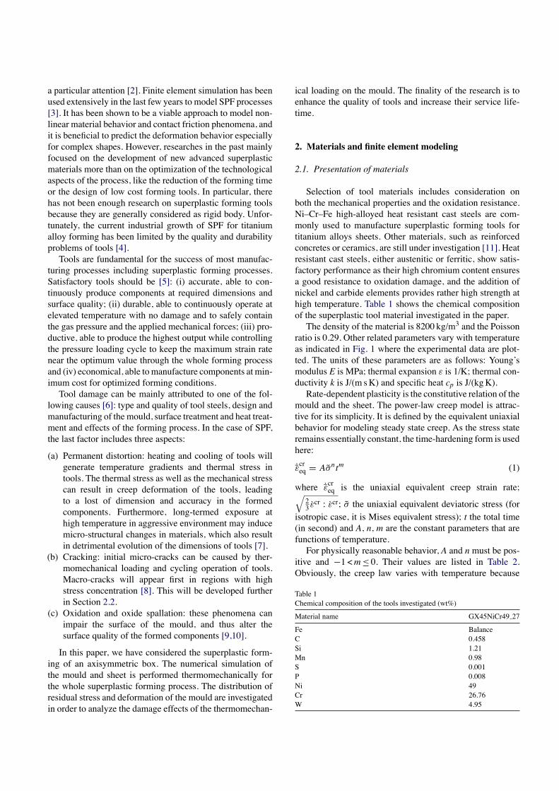
ratio is 0.29. Other related parameters vary with temperatureas indicated in Fig. 1 where the experimental data are plot-ted. The units of these parameters are as follows: Young’smodulus E is MPa; thermal expansion ε is 1/K; thermal con-ductivity k is J/(m sK) and specific heat cp is J/(kgK).Rate-dependent plasticity is the constitutive relation of the
mould and the sheet. The power-law creep model is attrac-tive for its simplicity. It is defined by the equivalent uniaxialbehavior for modeling steady state creep. As the stress stateremains essentially constant, the time-hardening form is usedhere:
˙̄εcreq = Aσ̃ntm (1)
where ˙̄εcreq is the uniaxial equivalent creep strain rate;√23 ε̇cr : ε̇cr; σ̃ the uniaxial equivalent deviatoric stress (for
isotropic case, it is Mises equivalent stress); t the total time(in second) and A, n, m are the constant parameters that arefunctions of temperature.For physically reasonable behavior, A and n must be pos-
itive and −1 <m ≤ 0. Their values are listed in Table 2.Obviously, the creep law varies with temperature because
Table 1Chemical composition of the tools investigated (wt%)
Material name GX45NiCr49 27
Fe BalanceC 0.458Si 1.21Mn 0.98S 0.001P 0.008Ni 49Cr 26.76W 4.95
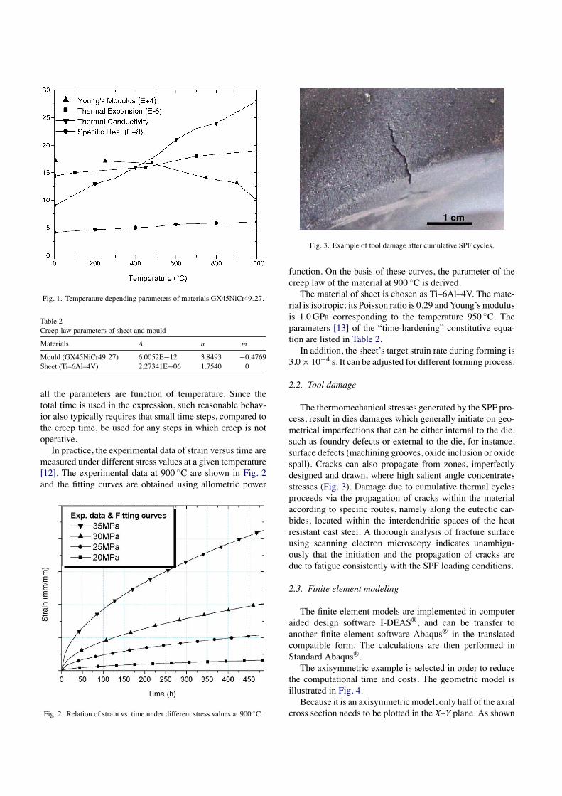
Fig. 1. Temperature depending parameters of materials GX45NiCr49 27.
Table 2Creep-law parameters of sheet and mould
Materials A n m
Mould (GX45NiCr49 27) 6.0052E−12 3.8493 −0.4769Sheet (Ti–6Al–4V) 2.27341E−06 1.7540 0
all the parameters are function of temperature. Since thetotal time is used in the expression, such reasonable behav-ior also typically requires that small time steps, compared tothe creep time, be used for any steps in which creep is notoperative.In practice, the experimental data of strain versus time are
measured under different stress values at a given temperature[12]. The experimental data at 900 ◦C are shown in Fig. 2and the fitting curves are obtained using allometric power
Fig. 2. Relation of strain vs. time under different stress values at 900 ◦C.
Fig. 3. Example of tool damage after cumulative SPF cycles.
function. On the basis of these curves, the parameter of thecreep law of the material at 900 ◦C is derived.The material of sheet is chosen as Ti–6Al–4V. The mate-
rial is isotropic; its Poisson ratio is 0.29 andYoung’smodulusis 1.0GPa corresponding to the temperature 950 ◦C. Theparameters [13] of the “time-hardening” constitutive equa-tion are listed in Table 2.In addition, the sheet’s target strain rate during forming is
3.0× 10⁻⁴ s. It can be adjusted for different forming process.
2.2. Tool damage
The thermomechanical stresses generated by the SPF pro-cess, result in dies damages which generally initiate on geo-metrical imperfections that can be either internal to the die,such as foundry defects or external to the die, for instance,surface defects (machining grooves, oxide inclusion or oxidespall). Cracks can also propagate from zones, imperfectlydesigned and drawn, where high salient angle concentratesstresses (Fig. 3). Damage due to cumulative thermal cyclesproceeds via the propagation of cracks within the materialaccording to specific routes, namely along the eutectic car-bides, located within the interdendritic spaces of the heatresistant cast steel. A thorough analysis of fracture surfaceusing scanning electron microscopy indicates unambigu-ously that the initiation and the propagation of cracks aredue to fatigue consistently with the SPF loading conditions.
2.3. Finite element modeling
The finite element models are implemented in computeraided design software I-DEAS®, and can be transfer toanother finite element software Abaqus® in the translatedcompatible form. The calculations are then performed inStandard Abaqus®.The axisymmetric example is selected in order to reduce
the computational time and costs. The geometric model isillustrated in Fig. 4.Because it is an axisymmetric model, only half of the axial
cross section needs to be plotted in the X–Y plane. As shown
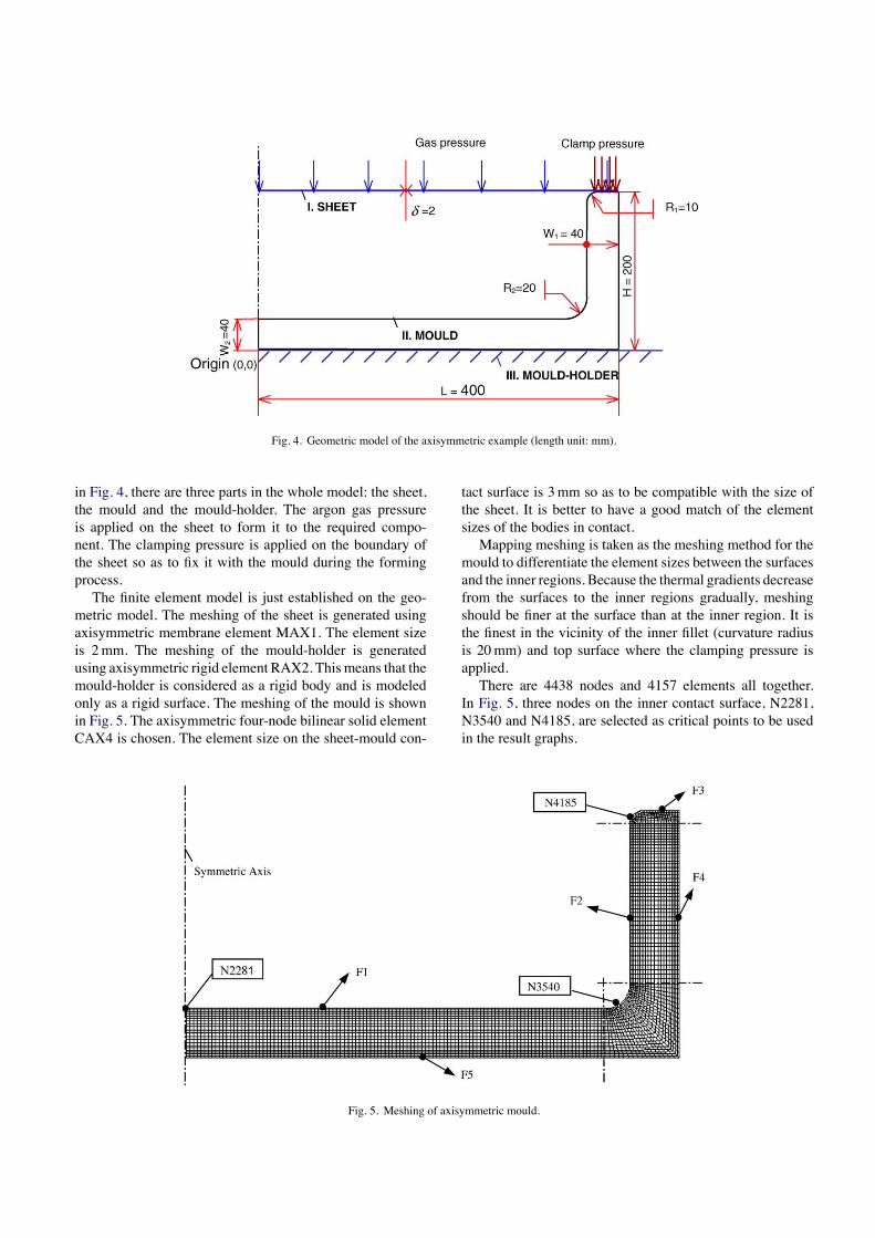
Fig. 4. Geometric model of the axisymmetric example (length unit: mm).
in Fig. 4, there are three parts in the whole model: the sheet,the mould and the mould-holder. The argon gas pressureis applied on the sheet to form it to the required compo-nent. The clamping pressure is applied on the boundary ofthe sheet so as to fix it with the mould during the formingprocess.The finite element model is just established on the geo-
metric model. The meshing of the sheet is generated usingaxisymmetric membrane element MAX1. The element sizeis 2mm. The meshing of the mould-holder is generatedusing axisymmetric rigid element RAX2. This means that themould-holder is considered as a rigid body and is modeledonly as a rigid surface. The meshing of the mould is shownin Fig. 5. The axisymmetric four-node bilinear solid elementCAX4 is chosen. The element size on the sheet-mould con-
tact surface is 3mm so as to be compatible with the size ofthe sheet. It is better to have a good match of the elementsizes of the bodies in contact.Mapping meshing is taken as the meshing method for the
mould to differentiate the element sizes between the surfacesand the inner regions. Because the thermal gradients decreasefrom the surfaces to the inner regions gradually, meshingshould be finer at the surface than at the inner region. It isthe finest in the vicinity of the inner fillet (curvature radiusis 20mm) and top surface where the clamping pressure isapplied.There are 4438 nodes and 4157 elements all together.
In Fig. 5, three nodes on the inner contact surface, N2281,N3540 and N4185, are selected as critical points to be usedin the result graphs.
Fig. 5. Meshing of axisymmetric mould.
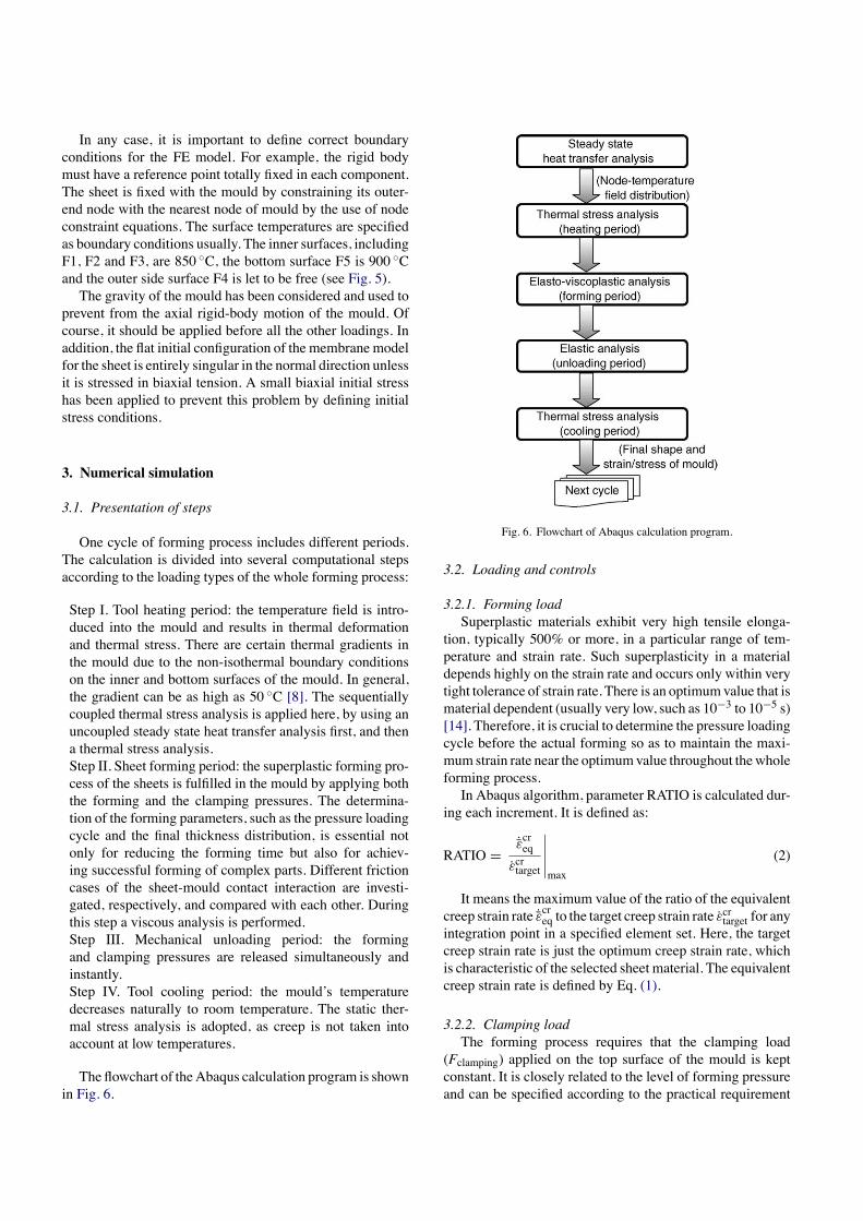
In any case, it is important to define correct boundaryconditions for the FE model. For example, the rigid bodymust have a reference point totally fixed in each component.The sheet is fixed with the mould by constraining its outer-end node with the nearest node of mould by the use of nodeconstraint equations. The surface temperatures are specifiedas boundary conditions usually. The inner surfaces, includingF1, F2 and F3, are 850 ◦C, the bottom surface F5 is 900 ◦Cand the outer side surface F4 is let to be free (see Fig. 5).The gravity of the mould has been considered and used to
prevent from the axial rigid-body motion of the mould. Ofcourse, it should be applied before all the other loadings. Inaddition, the flat initial configuration of the membrane modelfor the sheet is entirely singular in the normal direction unlessit is stressed in biaxial tension. A small biaxial initial stresshas been applied to prevent this problem by defining initialstress conditions.
3. Numerical simulation
3.1. Presentation of steps
One cycle of forming process includes different periods.The calculation is divided into several computational stepsaccording to the loading types of the whole forming process:
Step I. Tool heating period: the temperature field is intro-duced into the mould and results in thermal deformationand thermal stress. There are certain thermal gradients inthe mould due to the non-isothermal boundary conditionson the inner and bottom surfaces of the mould. In general,the gradient can be as high as 50 ◦C [8]. The sequentiallycoupled thermal stress analysis is applied here, by using anuncoupled steady state heat transfer analysis first, and thena thermal stress analysis.Step II. Sheet forming period: the superplastic forming pro-cess of the sheets is fulfilled in the mould by applying boththe forming and the clamping pressures. The determina-tion of the forming parameters, such as the pressure loadingcycle and the final thickness distribution, is essential notonly for reducing the forming time but also for achiev-ing successful forming of complex parts. Different frictioncases of the sheet-mould contact interaction are investi-gated, respectively, and compared with each other. Duringthis step a viscous analysis is performed.Step III. Mechanical unloading period: the formingand clamping pressures are released simultaneously andinstantly.Step IV. Tool cooling period: the mould’s temperaturedecreases naturally to room temperature. The static ther-mal stress analysis is adopted, as creep is not taken intoaccount at low temperatures.
The flowchart of theAbaqus calculation program is shownin Fig. 6.
Fig. 6. Flowchart of Abaqus calculation program.
3.2. Loading and controls
3.2.1. Forming loadSuperplastic materials exhibit very high tensile elonga-
tion, typically 500% or more, in a particular range of tem-perature and strain rate. Such superplasticity in a materialdepends highly on the strain rate and occurs only within verytight tolerance of strain rate. There is an optimumvalue that ismaterial dependent (usually very low, such as 10−3 to 10−5 s)[14]. Therefore, it is crucial to determine the pressure loadingcycle before the actual forming so as to maintain the maxi-mum strain rate near the optimumvalue throughout thewholeforming process.In Abaqus algorithm, parameter RATIO is calculated dur-
ing each increment. It is defined as:
RATIO =˙̄εcreq
ε̇crtarget
∣∣∣∣∣max
(2)
It means the maximum value of the ratio of the equivalentcreep strain rate ˙̄εcreq to the target creep strain rate ε̇crtarget for anyintegration point in a specified element set. Here, the targetcreep strain rate is just the optimum creep strain rate, whichis characteristic of the selected sheet material. The equivalentcreep strain rate is defined by Eq. (1).
3.2.2. Clamping loadThe forming process requires that the clamping load
(Fclamping) applied on the top surface of the mould is keptconstant. It is closely related to the level of forming pressureand can be specified according to the practical requirement
as,
Fclamping = const = 0.5MPa× Sformin g (3)
Thus
pclamping =FclampingSclamping
= Sformin g
Sclamping× 0.5MPa (4)
where F is the load, S the area and p is the pressure. Theclamping pressure is 2.8MPa for this example. In addition,the total loading applied on the mould is known as:
Fmould = Fformin g + Fclamping (5)
It actually varies during the sheet forming process due tothe automatic adjustment of the forming pressure.
3.2.3. Contact controlsThere are two contact types in our simulation. One takes
place between the sheet and the mould and belongs todeformable-to-deformable type; the other lies between themould and the mould-holder and belongs to deformable-to-rigid type. To force the calculation to converge successfully,the contact problems must be dealt carefully. Several impor-tant features are described in the following.It is critical to define the master surface and the slave
surface correctly for a contact pair at the beginning. Rigidsurfaces should act as themaster surface and the slave surfaceshould be attached to deformable bodies. For two deformablesurfaces, the master surface should be chosen from the sur-faces of the stiffer body or the surfaces with the coarser mesh.In the forming process, the mould is always chosen as themaster surface of the sheet-mould contact pair. Furthermore,the master surface should be element-based and the slave sur-face should be node-based. The meshes of the two surfacesshould match perfectly, or be finer for the slave surface thanfor the master surface. However, it is permitted for the mas-ter surface nodes to penetrate the slave surface in the Abaqusmaster–slave contact algorithm, but not vice versa.Contact along the perimeter of the master surface should
be avoided. Otherwise, the slave surface nodes can fall offthe free edge of the master surface and may be approachthe mating master surface from behind. So, it is necessaryto extend the master surface far enough in the finite-slidingcontact models.All the constraints of the model need to be checked to
avoid the overstraining problem. At the same time, insuffi-cient constraints should be avoided too. Because rigid bodymotion will occur when a body is not sufficiently restrained.
4. Results and discussion
4.1. Output related to sheet
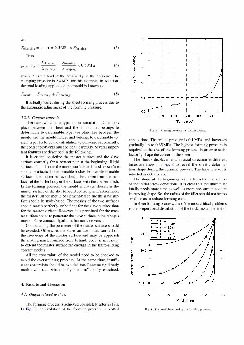
The forming process is achieved completely after 2917 s.In Fig. 7, the evolution of the forming pressure is plotted
Fig. 7. Forming pressure vs. forming time.
versus time. The initial pressure is 0.1MPa, and increasesgradually up to 0.65MPa. The highest forming pressure isrequired at the end of the forming process in order to satis-factorily shape the corner of the sheet.The sheet’s displacements in axial direction at different
times are shown in Fig. 8 to reveal the sheet’s deforma-tion shape during the forming process. The time interval isselected as 600 s or so.The shape at the beginning results from the application
of the initial stress conditions. It is clear that the inner filletfinally needs more time as well as more pressure to acquireits curving shape. So, the radius of the fillet should not be toosmall so as to reduce forming cost.In sheet forming process, one of themost critical problems
is the proportional distribution of the thickness at the end of
Fig. 8. Shape of sheet during the forming process.
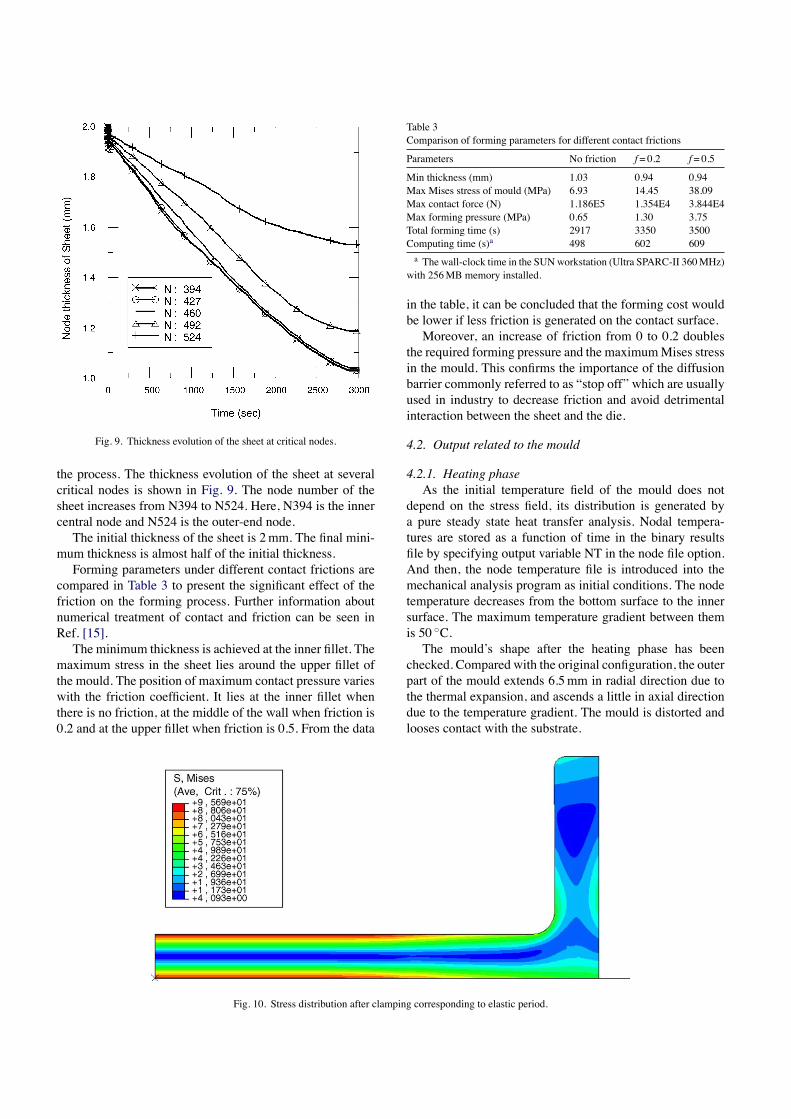
Fig. 9. Thickness evolution of the sheet at critical nodes.
the process. The thickness evolution of the sheet at severalcritical nodes is shown in Fig. 9. The node number of thesheet increases from N394 to N524. Here, N394 is the innercentral node and N524 is the outer-end node.The initial thickness of the sheet is 2mm. The final mini-
mum thickness is almost half of the initial thickness.Forming parameters under different contact frictions are
compared in Table 3 to present the significant effect of thefriction on the forming process. Further information aboutnumerical treatment of contact and friction can be seen inRef. [15].The minimum thickness is achieved at the inner fillet. The
maximum stress in the sheet lies around the upper fillet ofthe mould. The position of maximum contact pressure varieswith the friction coefficient. It lies at the inner fillet whenthere is no friction, at the middle of the wall when friction is0.2 and at the upper fillet when friction is 0.5. From the data
Table 3Comparison of forming parameters for different contact frictions
Parameters No friction f= 0.2 f= 0.5
Min thickness (mm) 1.03 0.94 0.94Max Mises stress of mould (MPa) 6.93 14.45 38.09Max contact force (N) 1.186E5 1.354E4 3.844E4Max forming pressure (MPa) 0.65 1.30 3.75Total forming time (s) 2917 3350 3500Computing time (s)a 498 602 609a The wall-clock time in the SUNworkstation (Ultra SPARC-II 360MHz)
with 256MB memory installed.
in the table, it can be concluded that the forming cost wouldbe lower if less friction is generated on the contact surface.Moreover, an increase of friction from 0 to 0.2 doubles
the required forming pressure and the maximumMises stressin the mould. This confirms the importance of the diffusionbarrier commonly referred to as “stop off” which are usuallyused in industry to decrease friction and avoid detrimentalinteraction between the sheet and the die.
4.2. Output related to the mould
4.2.1. Heating phaseAs the initial temperature field of the mould does not
depend on the stress field, its distribution is generated bya pure steady state heat transfer analysis. Nodal tempera-tures are stored as a function of time in the binary resultsfile by specifying output variable NT in the node file option.And then, the node temperature file is introduced into themechanical analysis program as initial conditions. The nodetemperature decreases from the bottom surface to the innersurface. The maximum temperature gradient between themis 50 ◦C.The mould’s shape after the heating phase has been
checked. Compared with the original configuration, the outerpart of the mould extends 6.5mm in radial direction due tothe thermal expansion, and ascends a little in axial directiondue to the temperature gradient. The mould is distorted andlooses contact with the substrate.
Fig. 10. Stress distribution after clamping corresponding to elastic period.
4.2.2. Clamping phaseBefore forming, the clamping load is applied in order to
ensure tightness of the mould prior to argon gas introduction.It brings the mould in contact with the substrate and intro-duces high stresses in the mould. Von Mises stresses afterclamping corresponding to an elastic calculation are shownin Fig. 10. The highest stresses (almost 100MPa) are reachedin the base surfaces of the mould (tensile at the top and com-pressive at the bottom).This values have to be compared to the true elastic limit
of the material at 900 ◦C, namely around 50MPa [16], tem-perature at which refractory steel behavior can be consideredas nearly perfect plastic materials.
4.2.3. Sheet forming phaseAfter applying the clamping load and forming pressure on
the mould, high temperature creep appears in the mould. Thestress is relaxed dramatically due to the creep phenomenon.
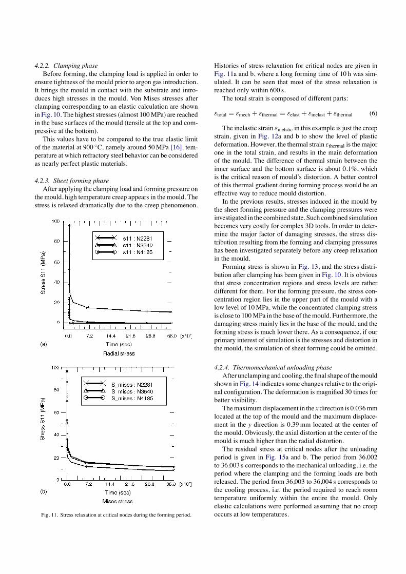
Fig. 11. Stress relaxation at critical nodes during the forming period.
Histories of stress relaxation for critical nodes are given inFig. 11a and b, where a long forming time of 10 h was sim-ulated. It can be seen that most of the stress relaxation isreached only within 600 s.The total strain is composed of different parts:
εtotal = εmech + εthermal = εelast + εinelast + εthermal (6)
The inelastic strain εinelstic in this example is just the creepstrain, given in Fig. 12a and b to show the level of plasticdeformation. However, the thermal strain εthermal is the majorone in the total strain, and results in the main deformationof the mould. The difference of thermal strain between theinner surface and the bottom surface is about 0.1%, whichis the critical reason of mould’s distortion. A better controlof this thermal gradient during forming process would be aneffective way to reduce mould distortion.In the previous results, stresses induced in the mould by
the sheet forming pressure and the clamping pressures wereinvestigated in the combined state. Such combined simulationbecomes very costly for complex 3D tools. In order to deter-mine the major factor of damaging stresses, the stress dis-tribution resulting from the forming and clamping pressureshas been investigated separately before any creep relaxationin the mould.Forming stress is shown in Fig. 13, and the stress distri-
bution after clamping has been given in Fig. 10. It is obviousthat stress concentration regions and stress levels are ratherdifferent for them. For the forming pressure, the stress con-centration region lies in the upper part of the mould with alow level of 10MPa, while the concentrated clamping stressis close to 100MPa in the base of themould. Furthermore, thedamaging stress mainly lies in the base of the mould, and theforming stress is much lower there. As a consequence, if ourprimary interest of simulation is the stresses and distortion inthe mould, the simulation of sheet forming could be omitted.
4.2.4. Thermomechanical unloading phaseAfter unclamping and cooling, the final shape of themould
shown in Fig. 14 indicates some changes relative to the origi-nal configuration. The deformation is magnified 30 times forbetter visibility.Themaximumdisplacement in the x direction is 0.036mm
located at the top of the mould and the maximum displace-ment in the y direction is 0.39mm located at the center ofthe mould. Obviously, the axial distortion at the center of themould is much higher than the radial distortion.The residual stress at critical nodes after the unloading
period is given in Fig. 15a and b. The period from 36,002to 36,003 s corresponds to the mechanical unloading, i.e. theperiod where the clamping and the forming loads are bothreleased. The period from 36,003 to 36,004 s corresponds tothe cooling process, i.e. the period required to reach roomtemperature uniformly within the entire the mould. Onlyelastic calculations were performed assuming that no creepoccurs at low temperatures.
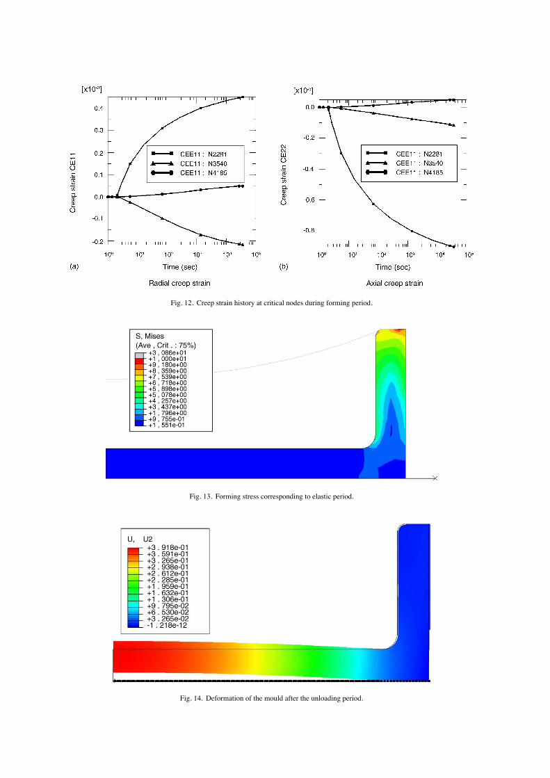
Fig. 12. Creep strain history at critical nodes during forming period.
Fig. 13. Forming stress corresponding to elastic period.
Fig. 14. Deformation of the mould after the unloading period.
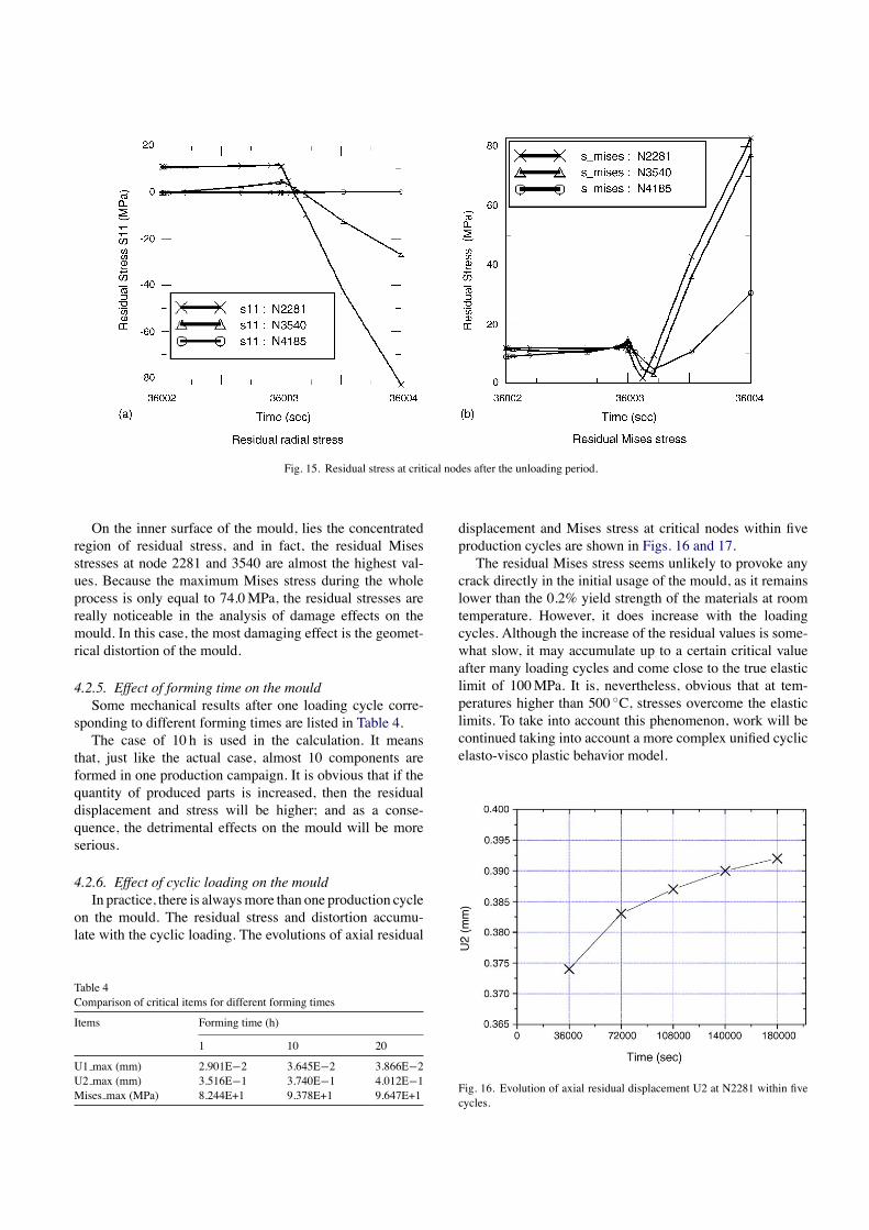
Fig. 15. Residual stress at critical nodes after the unloading period.
On the inner surface of the mould, lies the concentratedregion of residual stress, and in fact, the residual Misesstresses at node 2281 and 3540 are almost the highest val-ues. Because the maximum Mises stress during the wholeprocess is only equal to 74.0MPa, the residual stresses arereally noticeable in the analysis of damage effects on themould. In this case, the most damaging effect is the geomet-rical distortion of the mould.
4.2.5. Effect of forming time on the mouldSome mechanical results after one loading cycle corre-
sponding to different forming times are listed in Table 4.The case of 10 h is used in the calculation. It means
that, just like the actual case, almost 10 components areformed in one production campaign. It is obvious that if thequantity of produced parts is increased, then the residualdisplacement and stress will be higher; and as a conse-quence, the detrimental effects on the mould will be moreserious.
4.2.6. Effect of cyclic loading on the mouldIn practice, there is alwaysmore than one production cycle
on the mould. The residual stress and distortion accumu-late with the cyclic loading. The evolutions of axial residual
Table 4Comparison of critical items for different forming times
Items Forming time (h)
1 10 20
U1 max (mm) 2.901E−2 3.645E−2 3.866E−2U2 max (mm) 3.516E−1 3.740E−1 4.012E−1Mises max (MPa) 8.244E+1 9.378E+1 9.647E+1
displacement and Mises stress at critical nodes within fiveproduction cycles are shown in Figs. 16 and 17.The residual Mises stress seems unlikely to provoke any
crack directly in the initial usage of the mould, as it remainslower than the 0.2% yield strength of the materials at roomtemperature. However, it does increase with the loadingcycles. Although the increase of the residual values is some-what slow, it may accumulate up to a certain critical valueafter many loading cycles and come close to the true elasticlimit of 100MPa. It is, nevertheless, obvious that at tem-peratures higher than 500 ◦C, stresses overcome the elasticlimits. To take into account this phenomenon, work will becontinued taking into account a more complex unified cyclicelasto-visco plastic behavior model.
Fig. 16. Evolution of axial residual displacement U2 at N2281 within fivecycles.
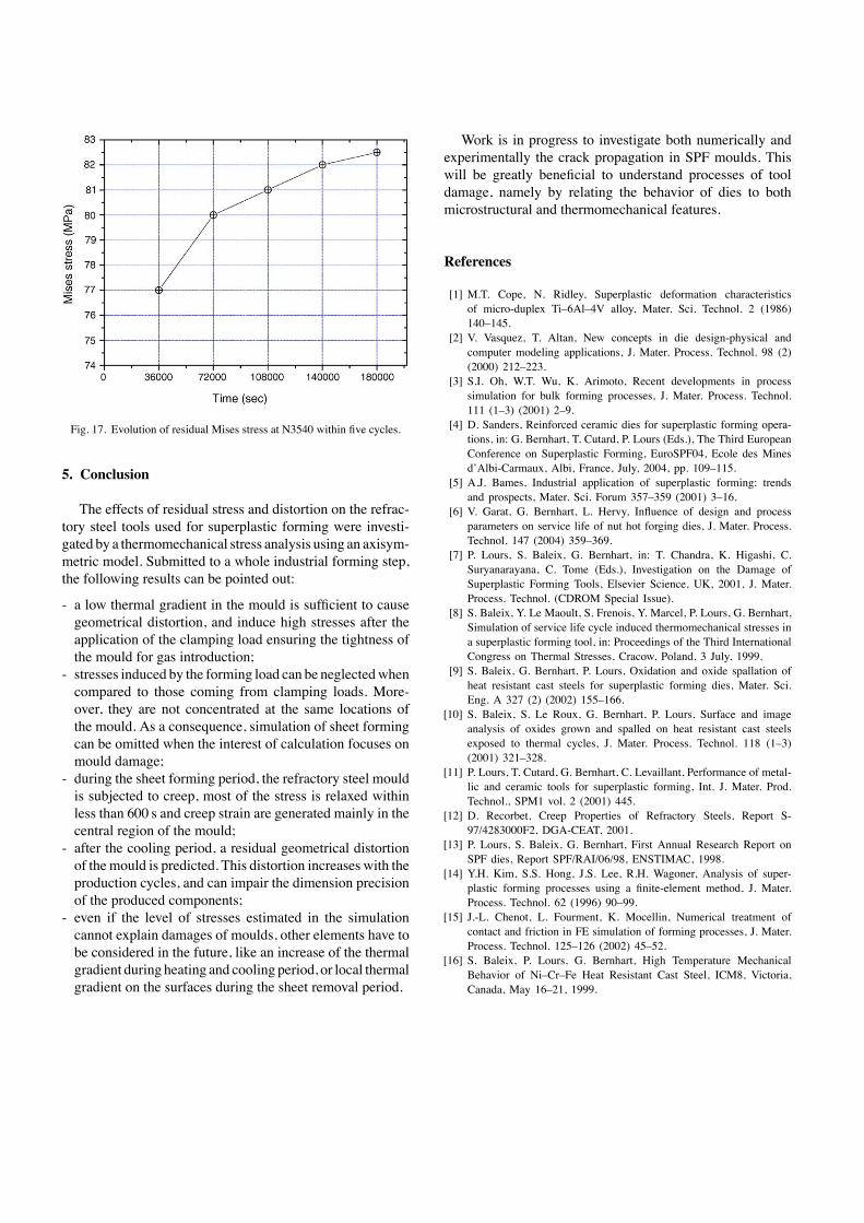
Fig. 17. Evolution of residual Mises stress at N3540 within five cycles.
5. Conclusion
The effects of residual stress and distortion on the refrac-tory steel tools used for superplastic forming were investi-gated by a thermomechanical stress analysis using an axisym-metric model. Submitted to a whole industrial forming step,the following results can be pointed out:
- a low thermal gradient in the mould is sufficient to causegeometrical distortion, and induce high stresses after theapplication of the clamping load ensuring the tightness ofthe mould for gas introduction;
- stresses induced by the forming load can be neglectedwhencompared to those coming from clamping loads. More-over, they are not concentrated at the same locations ofthe mould. As a consequence, simulation of sheet formingcan be omitted when the interest of calculation focuses onmould damage;
- during the sheet forming period, the refractory steel mouldis subjected to creep, most of the stress is relaxed withinless than 600 s and creep strain are generated mainly in thecentral region of the mould;
- after the cooling period, a residual geometrical distortionof themould is predicted. This distortion increases with theproduction cycles, and can impair the dimension precisionof the produced components;
- even if the level of stresses estimated in the simulationcannot explain damages of moulds, other elements have tobe considered in the future, like an increase of the thermalgradient during heating and cooling period, or local thermalgradient on the surfaces during the sheet removal period.
Work is in progress to investigate both numerically andexperimentally the crack propagation in SPF moulds. Thiswill be greatly beneficial to understand processes of tooldamage, namely by relating the behavior of dies to bothmicrostructural and thermomechanical features.
References
[1] M.T. Cope, N. Ridley, Superplastic deformation characteristicsof micro-duplex Ti–6Al–4V alloy, Mater. Sci. Technol. 2 (1986)140–145.
[2] V. Vasquez, T. Altan, New concepts in die design-physical andcomputer modeling applications, J. Mater. Process. Technol. 98 (2)(2000) 212–223.
[3] S.I. Oh, W.T. Wu, K. Arimoto, Recent developments in processsimulation for bulk forming processes, J. Mater. Process. Technol.111 (1–3) (2001) 2–9.
[4] D. Sanders, Reinforced ceramic dies for superplastic forming opera-tions, in: G. Bernhart, T. Cutard, P. Lours (Eds.), The Third EuropeanConference on Superplastic Forming, EuroSPF04, Ecole des Minesd’Albi-Carmaux, Albi, France, July, 2004, pp. 109–115.
[5] A.J. Bames, Industrial application of superplastic forming: trendsand prospects, Mater. Sci. Forum 357–359 (2001) 3–16.
[6] V. Garat, G. Bernhart, L. Hervy, Influence of design and processparameters on service life of nut hot forging dies, J. Mater. Process.Technol. 147 (2004) 359–369.
[7] P. Lours, S. Baleix, G. Bernhart, in: T. Chandra, K. Higashi, C.Suryanarayana, C. Tome (Eds.), Investigation on the Damage ofSuperplastic Forming Tools, Elsevier Science, UK, 2001, J. Mater.Process. Technol. (CDROM Special Issue).
[8] S. Baleix, Y. Le Maoult, S. Frenois, Y. Marcel, P. Lours, G. Bernhart,Simulation of service life cycle induced thermomechanical stresses ina superplastic forming tool, in: Proceedings of the Third InternationalCongress on Thermal Stresses, Cracow, Poland, 3 July, 1999.
[9] S. Baleix, G. Bernhart, P. Lours, Oxidation and oxide spallation ofheat resistant cast steels for superplastic forming dies, Mater. Sci.Eng. A 327 (2) (2002) 155–166.
[10] S. Baleix, S. Le Roux, G. Bernhart, P. Lours, Surface and imageanalysis of oxides grown and spalled on heat resistant cast steelsexposed to thermal cycles, J. Mater. Process. Technol. 118 (1–3)(2001) 321–328.
[11] P. Lours, T. Cutard, G. Bernhart, C. Levaillant, Performance of metal-lic and ceramic tools for superplastic forming, Int. J. Mater. Prod.Technol., SPM1 vol. 2 (2001) 445.
[12] D. Recorbet, Creep Properties of Refractory Steels, Report S-97/4283000F2, DGA-CEAT, 2001.
[13] P. Lours, S. Baleix, G. Bernhart, First Annual Research Report onSPF dies, Report SPF/RAI/06/98, ENSTIMAC, 1998.
[14] Y.H. Kim, S.S. Hong, J.S. Lee, R.H. Wagoner, Analysis of super-plastic forming processes using a finite-element method, J. Mater.Process. Technol. 62 (1996) 90–99.
[15] J.-L. Chenot, L. Fourment, K. Mocellin, Numerical treatment ofcontact and friction in FE simulation of forming processes, J. Mater.Process. Technol. 125–126 (2002) 45–52.
[16] S. Baleix, P. Lours, G. Bernhart, High Temperature MechanicalBehavior of Ni–Cr–Fe Heat Resistant Cast Steel, ICM8, Victoria,Canada, May 16–21, 1999.