Embed Size (px)
Citation preview
Journal of Thermal Engineering, Vol. 6, No. 6, Special Issue 12, pp. 226-246, December, 2020 Yildiz Technical University Press, Istanbul, Turkey
This paper was recommended for publication in revised form by Regional Editor N. Filiz Özdil
School of Engineering, Department of Environment, University of Tehran, 1 *E-mail address: [email protected], [email protected] Orcid id: 0000-0002-3910-6828, 0000-0003-2039-9859 Manuscript Received 05 August 2018, Accepted 15 September 2018
THERMODYNAMIC AND ENVIRONMENTAL COMPARATIVE INVESTIGATION AND OPTIMIZATION OF LANDFILL VS. INCINERATION FOR MUNICIPAL SOLID
WASTE: A CASE STUDY IN VARAMIN, IRAN
1Mehrnoosh Moghaddam*, 1Amir Ghasemi
ABSTRACT
Waste to energy (WtE) introduces an appropriate solution for municipal solid waste (MSW) disposal and
greenhouse gas emission reduction. In this study, for Varamin MSW management, a gas turbine plant with heat
recovery unit that is fed by landfill gas (LFG) and combined heat and power (CHP) incineration plant is
investigated and compared as two WtE systems to reveal the best plant effectively. Exergy and environmental
analyses of two systems are performed. Moreover, the effects of key parameters as decision variables on the
energy and exergy efficiencies are identified by sensitive analysis of both systems. Multi-objective optimization
of thermal and exergy efficiencies are then done by using Genetic Algorithm (GA) for each studied system. As a
result, Furnace in incineration system and Combustion Chamber in landfill system have the most exergy
destruction rate. Also, optimization results show that thermal and exergy effectiveness for landfill system are
improved by 7.01% and 6.53% respectively; these values for incineration system are calculated to be 45.35% and
92.75% respectively.
Keywords: Waste to Energy, Exergy, Environmental Analysis, Landfill Plant, Incineration Plant, Multi
Objective Optimization
INTRODUCTION
An evolutionary of the primary and second laws of the thermodynamic was carried out for a 14.25 MW
cogeneration system, in Turkey. The energy demand of the patron was around 10.5 MW whereas the cogeneration
system generated practically 1.35 times the patron demand. The results illustrated that the highest amount of the
irreversibility happened within the boiler, and the economizer and stack had the more important irreversibilities,
respectively [1]. The analyses of fundamental laws of thermodynamics were accomplished for a 6.5 MW power
plant located in Adana, Turkey. Parts of the system, tested in that study, were classified as a fluidized bed coal
combustor, a heat recovery steam generator, an economizer, fans, pumps, a cyclone, and a chimney. All of the
parts were assessed and the energy and exergy analyses were investigated for all of the system components [2].
The thermodynamic investigation was fulfilled to indicate the performance of the 14.25 MW cogeneration
proposed energy system and the parts of the system were observed and thermodynamic performance assessments
were evaluated. The produced results were illustrated that major exergy destruction occurred in the boiler, which
was 42% of the whole system irreversibility. Moreover, the energy efficiencies of the components were calculated
[3]. The assessment of a 6.5 MW energy system was performed based on thermodynamic indicators. The energetic
and exergetic investigation applied to all of the equipment separately and the primary source of irreversibility and
exergy destruction rate was derived. In that survey higher excess air induces the decrease of combustion exergy
efficiency in fluidized bed coal combustor. This drawback could be decrement by decreasing the air flow rate in
that part of the system [4]. The exergy and exergoeconomic assessment of a biogas engine powered energy system
in a wastewater treatment plant located in Turkey were performed to detecting the significant exergy destruction
and calculating operating, maintenance, capital investment, the total cost of the system and produced electricity
cost. The outputs illustrated that the gas engine and exhaust gas heat exchanger had been had the highest rate of
exergy destruction in the proposed system, respectively. Also, the total cost of the system was founded 28.64
US$/h, and the exergy cost and electricity production cost in the turbine were founded 4.87 US$/h and 11.32
US$/GJ [5]. Performance analyses of multi-effect desalination coupled to a combined cooling, heating and power
energy system were accomplished. The primary goal of that survey was analyzing the thermodynamic
performance of an integrated system. EES software was used to the modeling of the system and outputs was
indicated that overall efficiency of the integrated system is reached to 84%. Moreover, the parameters that had
detected to improve the performance of the system was analyzed [6].
Journal of Thermal Engineering, Research Article, Vol. 6, No. 6, Special Issue 12, pp. 226-246, December, 2020
227
MSW (Municipal Solid Waste) is considered as a renewable energy source because wastes are
continuously produced in the world; hence energy from waste can be a significant way to reduce energy production
from non-renewable energy sources such as fossil fuels and GHG (Greenhouse Gas) emissions [7],[8]. The various
form of utilization of municipal solid waste in order to energy producing in the developed countries was carried
out to indicate the efficient way. The Tokyo that is located in Japan has been considered to a case study to this
aim. After assessment of potential scenarios, the best option was selected. In that selected option the energy
efficiency will reach 65.95% in 2030. Moreover, in that scenario 6.58 × 10⁵ tons of CO2 emissions will reduce.
the article provided a practical guide for founding a more efficient MSW management system for the purpose of
a low carbon society [9]. The analyzing of the exergy efficiency of electricity production of the landfill from a
landfill that located in Greece was carried out. The main aim in that survey was clarifying this issue that how the
extension of the landfill influence power generation. That potential of every form of extensions was compared,
and the results were presented [10]. Advanced exergy and environmental analysis of a steam cycle of a municipal
solid waste incineration plant were accomplished to determine the thermodynamic performance of the main parts
such as exergy annihilation and energy efficiency. To detecting the potential for improvement in the incineration
steam cycle, an advanced energetic assessment was done in four categories. The results illustrated that total plant
exergy destruction could be decreased by 8.4%, through improvements in efficiency at plant components
considering the best available technologies and operating parameters [11]. Thermodynamic evaluation of a
municipal solid waste-to-energy boiler for three case studies in Tehran was conducted, and the main reasons of
irreversibility within the boiler was detected. Moreover, the energy and exergy analysis were then accomplished
for all components, and the entire boiler and results unmasked that the irreversibility in the furnace, with 52,617.3
kJ. s−1 was the primary cause of the exergy annihilation. Besides, the overall energetic and exergetic efficiency
of the mentioned boiler were calculated as 78.7 and 16.0 %, respectively [12].
The waste to energy (WtE) conversion systems are used to convert solid waste into fuels, electric power
and heat. They are classified as the thermochemical and the biochemical methods [13]. Waste incineration is most
commonly used as the thermo-chemical process. Complete oxidation of organic substances in waste materials
occurs during the incineration process [14]. Energy recovery is performed by using the heat content of the
combustion products. The temperature of products depends on LHV (Low Heating Value), moisture and ash
content of MSW. Minimum range of the solid waste LHV that waste can be burnt without auxiliary fuel is 5-
7GJ/Mg [15]. Energy productions in this process can be only electricity or combined heat and power (CHP); But
CHP is found to perform better in life cycle assessment (LCA) and system efficiency evaluation than only
electricity production [16]. One of the biochemical processes in waste to energy systems is Biogas produced from
organic waste material in the landfill site. It can be used as fuel directly or produce electricity and heat [17].
Recently biogas-based CHP systems are used widely in the world because of these systems use less fuel than
separate power and heat systems [18],[19]. In this research, two waste to energy systems: a landfill plant, which
is fed by LFG (Landfill Gas), including a gas turbine associated with a heat recovery unit and a CHP incineration
plant are investigated from the standpoints of energy, exergy and environmentally based on the Varamin, Iran
data in order to designate the best system efficiently and environmentally. For this purpose, the thermodynamic
and exergy efficiencies and total GHG emissions are calculated by utilizing mass, energy and exergy balances to
each system using EES software [20]. The effects of key thermodynamic parameters on the energy and exergy
efficiencies are then identified by system sensitive analysis. Afterward, both systems are optimized to maximize
the thermal and exergy efficiencies simultaneously employing genetic algorithm programming using MATLAB
software [21].
MATERIALS AND METHODS
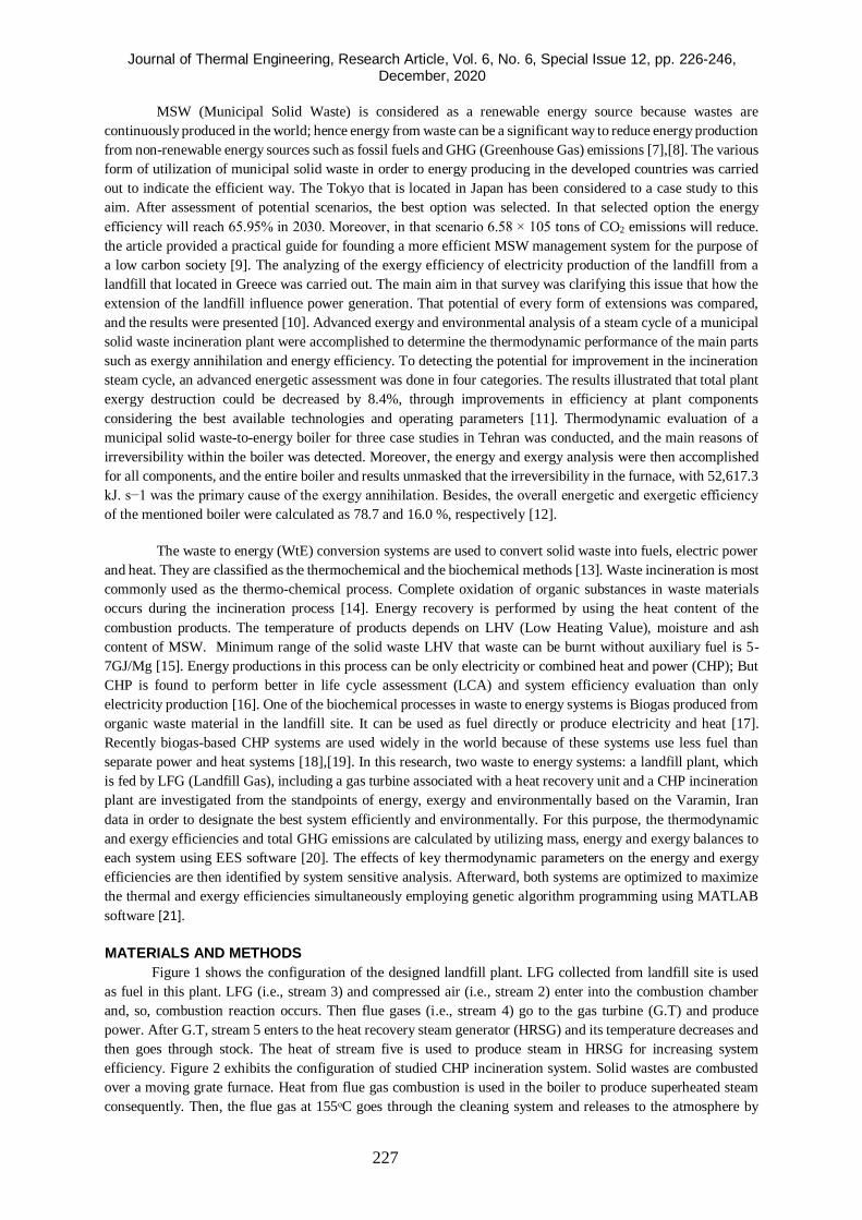
Figure 1 shows the configuration of the designed landfill plant. LFG collected from landfill site is used
as fuel in this plant. LFG (i.e., stream 3) and compressed air (i.e., stream 2) enter into the combustion chamber
and, so, combustion reaction occurs. Then flue gases (i.e., stream 4) go to the gas turbine (G.T) and produce
power. After G.T, stream 5 enters to the heat recovery steam generator (HRSG) and its temperature decreases and
then goes through stock. The heat of stream five is used to produce steam in HRSG for increasing system
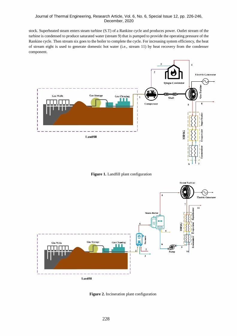
efficiency. Figure 2 exhibits the configuration of studied CHP incineration system. Solid wastes are combusted
over a moving grate furnace. Heat from flue gas combustion is used in the boiler to produce superheated steam
consequently. Then, the flue gas at 155ᵒC goes through the cleaning system and releases to the atmosphere by
Journal of Thermal Engineering, Research Article, Vol. 6, No. 6, Special Issue 12, pp. 226-246, December, 2020
228
stock. Superheated steam enters steam turbine (S.T) of a Rankine cycle and produces power. Outlet stream of the
turbine is condensed to produce saturated water (stream 9) that is pumped to provide the operating pressure of the
Rankine cycle. Then stream six goes to the boiler to complete the cycle. For increasing system efficiency, the heat
of stream eight is used to generate domestic hot water (i.e., stream 11) by heat recovery from the condenser
component.
Figure 1. Landfill plant configuration
Figure 2. Incineration plant configuration
Journal of Thermal Engineering, Research Article, Vol. 6, No. 6, Special Issue 12, pp. 226-246, December, 2020
229
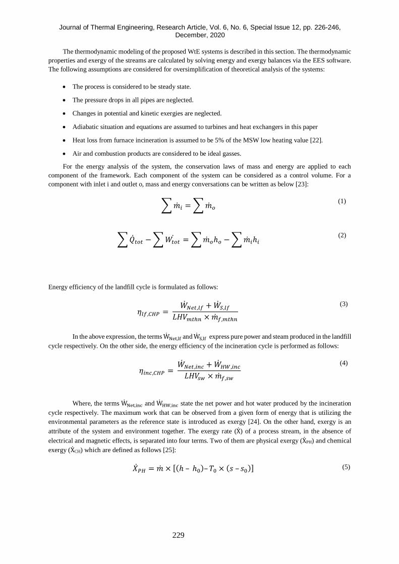
The thermodynamic modeling of the proposed WtE systems is described in this section. The thermodynamic
properties and exergy of the streams are calculated by solving energy and exergy balances via the EES software.
The following assumptions are considered for oversimplification of theoretical analysis of the systems:
• The process is considered to be steady state.
• The pressure drops in all pipes are neglected.
• Changes in potential and kinetic exergies are neglected.
• Adiabatic situation and equations are assumed to turbines and heat exchangers in this paper
• Heat loss from furnace incineration is assumed to be 5% of the MSW low heating value [22].
• Air and combustion products are considered to be ideal gasses.
For the energy analysis of the system, the conservation laws of mass and energy are applied to each
component of the framework. Each component of the system can be considered as a control volume. For a
component with inlet i and outlet o, mass and energy conversations can be written as below [23]:
∑ ��𝑖 = ∑ ��𝑜 (1)
∑ ��𝑡𝑜𝑡 − ∑ 𝑊𝑡𝑜𝑡 = ∑ ��𝑜ℎ𝑜 − ∑ ��𝑖ℎ𝑖
(2)
Energy efficiency of the landfill cycle is formulated as follows:
𝜂𝑙𝑓,𝐶𝐻𝑃 = ��𝑁𝑒𝑡,𝑙𝑓 + ��𝑆,𝑙𝑓
𝐿𝐻𝑉𝑚𝑡ℎ𝑛 × ��𝑓,𝑚𝑡ℎ𝑛
(3)
In the above expression, the terms WNet,lf and WS,lf express pure power and steam produced in the landfill
cycle respectively. On the other side, the energy efficiency of the incineration cycle is performed as follows:
𝜂𝑖𝑛𝑐,𝐶𝐻𝑃 = ��𝑁𝑒𝑡,𝑖𝑛𝑐 + ��𝐻𝑊,𝑖𝑛𝑐
𝐿𝐻𝑉𝑠𝑤 × ��𝑓,𝑠𝑤
(4)
Where, the terms WNet,inc and WHW,inc state the net power and hot water produced by the incineration
cycle respectively. The maximum work that can be observed from a given form of energy that is utilizing the
environmental parameters as the reference state is introduced as exergy [24]. On the other hand, exergy is an
attribute of the system and environment together. The exergy rate (X) of a process stream, in the absence of
electrical and magnetic effects, is separated into four terms. Two of them are physical exergy (XPH) and chemical
exergy (XCH) which are defined as follows [25]:
��𝑃𝐻 = �� × [(ℎ – ℎ0)– 𝑇0 × (𝑠 – 𝑠0)]
(5)
Journal of Thermal Engineering, Research Article, Vol. 6, No. 6, Special Issue 12, pp. 226-246, December, 2020
230
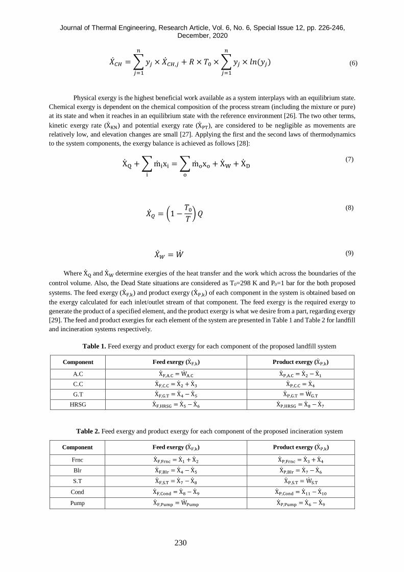
��𝐶𝐻 = ∑ 𝑦𝑗 × ��𝐶𝐻,𝑗
𝑛
𝑗=1
+ 𝑅 × 𝑇0 × ∑ 𝑦𝑗 × 𝑙𝑛(𝑦𝑗)
𝑛
𝑗=1
(6)
Physical exergy is the highest beneficial work available as a system interplays with an equilibrium state.
Chemical exergy is dependent on the chemical composition of the process stream (including the mixture or pure)
at its state and when it reaches in an equilibrium state with the reference environment [26]. The two other terms,
kinetic exergy rate (XKN) and potential exergy rate (XPT), are considered to be negligible as movements are
relatively low, and elevation changes are small [27]. Applying the first and the second laws of thermodynamics
to the system components, the exergy balance is achieved as follows [28]:
XQ + ∑ mixi
i
= ∑ moxo
o
+ XW + XD (7)
��𝑄 = (1 −𝑇0
𝑇) 𝑄
(8)
��𝑊 = �� (9)
Where XQ and XW determine exergies of the heat transfer and the work which across the boundaries of the
control volume. Also, the Dead State situations are considered as T0=298 K and P0=1 bar for the both proposed
systems. The feed exergy (XF,k) and product exergy (XP,k) of each component in the system is obtained based on
the exergy calculated for each inlet/outlet stream of that component. The feed exergy is the required exergy to
generate the product of a specified element, and the product exergy is what we desire from a part, regarding exergy
[29]. The feed and product exergies for each element of the system are presented in Table 1 and Table 2 for landfill
and incineration systems respectively.
Table 1. Feed exergy and product exergy for each component of the proposed landfill system
Component Feed exergy (XF,k) Product exergy (XP,k)
A.C XF,A.C = WA.C XP,A.C = X2 − X1
C.C XF,C.C = X2 + X3 XP,C.C = X4
G.T XF,G.T = X4 − X5 XP,G.T = WG.T
HRSG XF,HRSG = X5 − X6 XP,HRSG = X8 − X7
Table 2. Feed exergy and product exergy for each component of the proposed incineration system
Component Feed exergy (XF,k) Product exergy (XP,k)
Frnc XF,Frnc = X1 + X2 XP,Frnc = X3 + X4
Blr XF,Blr = X4 − X5 XP,Blr = X7 − X6
S.T XF,S.T = X7 − X8 XP,S.T = WS.T
Cond XF,Cond = X8 − X9 XP,Cond = X11 − X10
Pump XF,Pump = WPump XP,Pump = X6 − X9
Journal of Thermal Engineering, Research Article, Vol. 6, No. 6, Special Issue 12, pp. 226-246, December, 2020
231
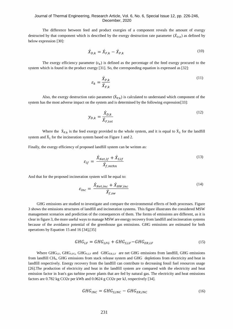
The difference between feed and product exergies of a component reveals the amount of exergy
destructed by that component which is described by the exergy destruction rate parameter (��𝐷,𝑘) as defined by
below expression [30]:
��𝐷,𝑘 = ��𝐹,𝑘 − ��𝑃,𝑘 (10)
The exergy efficiency parameter (ε𝑘) is defined as the percentage of the feed exergy procured to the
system which is found in the product exergy [31]. So, the corresponding equation is expressed as [32]:
𝜀𝑘 =��𝑃,𝑘
��𝐹,𝑘
(11)
Also, the exergy destruction ratio parameter (XP,k) is calculated to understand which component of the
system has the most adverse impact on the system and is determined by the following expression[33]:
𝑦𝐷,𝑘 =��𝐷,𝑘
��𝐹,𝑡𝑜𝑡
(12)
Where the XP,k is the feed exergy provided to the whole system, and it is equal to X3 for the landfill
system and X1 for the incineration system based on Figure 1 and 2.
Finally, the exergy efficiency of proposed landfill system can be written as:
𝜀𝑙𝑓 = ��𝑁𝑒𝑡,𝑙𝑓 + ��𝑆,𝑙𝑓
��𝑓,𝑚𝑡ℎ𝑛
(13)
And that for the proposed incineration system will be equal to:
𝜀𝑖𝑛𝑐 = ��𝑁𝑒𝑡,𝑖𝑛𝑐 + ��𝐻𝑊,𝑖𝑛𝑐
��𝑓,𝑠𝑤
(14)
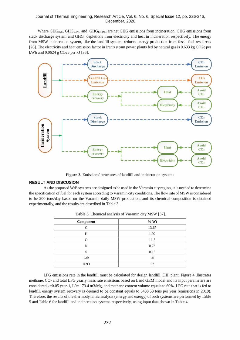
GHG emissions are studied to investigate and compare the environmental effects of both processes. Figure
3 shows the emissions structures of landfill and incineration systems. This figure illustrates the considered MSW
management scenarios and prediction of the consequences of them. The forms of emissions are different, as it is
clear in figure 3, the more useful ways to manage MSW are energy recovery from landfill and incineration systems
because of the avoidance potential of the greenhouse gas emissions. GHG emissions are estimated for both
operations by Equation 15 and 16 [34],[35]
𝐺𝐻𝐺𝐿𝐹 = 𝐺𝐻𝐺𝐿𝐹𝐺 + 𝐺𝐻𝐺𝑆,𝐿𝐹−𝐺𝐻𝐺𝐸𝑅,𝐿𝐹 (15)
Where GHGLF, GHGLFG, GHGS,LF and GHGER,LF are net GHG emissions from landfill, GHG emissions
from landfill CH4, GHG emissions from stack release system and GHG depletions from electricity and heat in
landfill respectively. Energy recovery from the landfill can contribute to decreasing fossil fuel resources usage
[26].The production of electricity and heat in the landfill system are compared with the electricity and heat
emission factor in Iran's gas turbine power plants that are fed by natural gas. The electricity and heat emissions
factors are 0.782 kg CO2e per kWh and 0.0624 g CO2e per kJ, respectively [34].
𝐺𝐻𝐺𝐼𝑁𝐶 = 𝐺𝐻𝐺𝑆,𝐼𝑁𝐶 − 𝐺𝐻𝐺𝐸𝑅,𝐼𝑁𝐶 (16)
Journal of Thermal Engineering, Research Article, Vol. 6, No. 6, Special Issue 12, pp. 226-246, December, 2020
232
Where GHGINC, GHGS,INC and GHGER,INC are net GHG emissions from incineration, GHG emissions from
stack discharge system and GHG depletions from electricity and heat in incineration respectively. The energy
from MSW incineration system, like the landfill system, reduces energy production from fossil fuel resources
[26]. The electricity and heat emission factor in Iran's steam power plants fed by natural gas is 0.633 kg CO2e per
kWh and 0.0624 g CO2e per kJ [36].
Figure 3. Emissions' structures of landfill and incineration systems
RESULT AND DISCUSION
As the proposed WtE systems are designed to be used in the Varamin city region, it is needed to determine
the specification of fuel for each system according to Varamin city conditions. The flow rate of MSW is considered
to be 200 tons/day based on the Varamin daily MSW production, and its chemical composition is obtained
experimentally, and the results are described in Table 3.
Table 3. Chemical analysis of Varamin city MSW [37].
% Wt Component
13.67 C
1.92 H
11.5 O
0.78 N
0.13 S
20 Ash
52 H2O
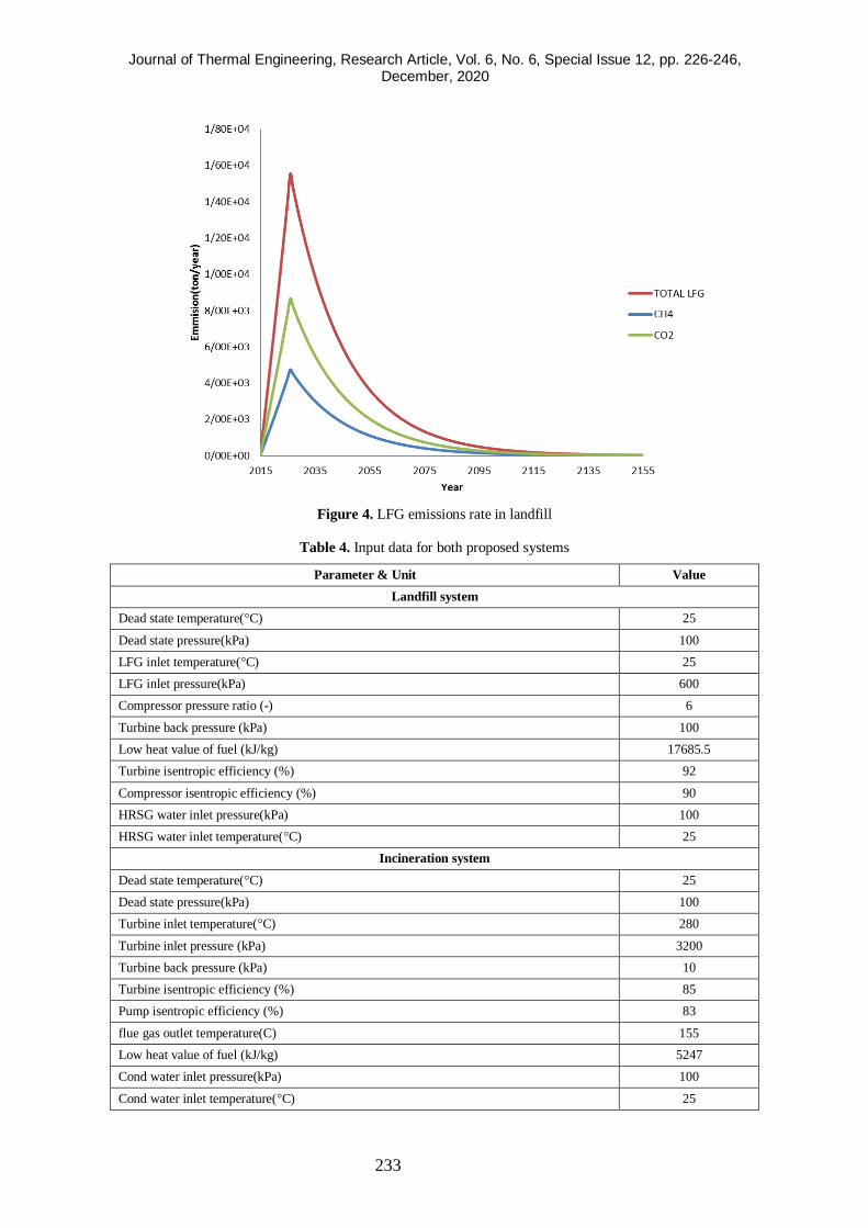
LFG emissions rate in the landfill must be calculated for design landfill CHP plant. Figure 4 illustrates
methane, CO2 and total LFG yearly mass rate emissions based on Land GEM model and its input parameters are
considered k=0.05 year-1, L0= 173.4 m3/Mg, and methane content volume equals to 60%. LFG rate that is fed to
landfill energy system recovery is deemed to be constant equals to 5438.53 tons per year (emissions in 2019).
Therefore, the results of the thermodynamic analysis (energy and exergy) of both systems are performed by Table
5 and Table 6 for landfill and incineration systems respectively, using input data shown in Table 4.
Journal of Thermal Engineering, Research Article, Vol. 6, No. 6, Special Issue 12, pp. 226-246, December, 2020
233
Figure 4. LFG emissions rate in landfill
Table 4. Input data for both proposed systems
Parameter & Unit Value
Landfill system
Dead state temperature(°C) 25
Dead state pressure(kPa) 100
LFG inlet temperature(°C) 25
LFG inlet pressure(kPa) 600
Compressor pressure ratio (-) 6
Turbine back pressure (kPa) 100
Low heat value of fuel (kJ/kg) 17685.5
Turbine isentropic efficiency (%) 92
Compressor isentropic efficiency (%) 90
HRSG water inlet pressure(kPa) 100
HRSG water inlet temperature(°C) 25
Incineration system
Dead state temperature(°C) 25
Dead state pressure(kPa) 100
Turbine inlet temperature(°C) 280
Turbine inlet pressure (kPa) 3200
Turbine back pressure (kPa) 10
Turbine isentropic efficiency (%) 85
Pump isentropic efficiency (%) 83
flue gas outlet temperature(C) 155
Low heat value of fuel (kJ/kg) 5247
Cond water inlet pressure(kPa) 100
Cond water inlet temperature(°C) 25

Journal of Thermal Engineering, Research Article, Vol. 6, No. 6, Special Issue 12, pp. 226-246, December, 2020
234
Table 5. Process streams output data (landfill system)
State Substance Temperature
(°C)
Pressure
(kPa)
Mass flow
(kg/s)
Physical
Exergy (MW)
Chemical
Exergy
(MW)
Total Exergy
(MW)
1 air 25 101.325 2.143 0 0 0
2 air 234.34 607.95 2.143 0.442 0 0.442
3 LFG 25 607.95 0.1723 -0.186 3.184 2.998
4 combustion
products 1279.53 607.95 2.3150 2.542 0.114 2.656
5 combustion
products 807.48 101.325 2.3150 1.091 0.114 1.205
6 combustion
products 300 101.325 2.3150 0.213 0.114 0.328
7 water 25 101.325 0.485 0 0.001 0.001
8 steam 197.466 101.325 0.485 0.277 0.001 0.278
Table 6. Process streams output data (incineration system)
State Substance Temperature
(°C)
Pressure
(kPa)
Mass flow
(kg/s)
Physical
Exergy (MW)
Chemical
Exergy
(MW)
Total Exergy
(MW)
1 MSW 25 100 2.315 0 19.12 19.12
2 Air 25 100 5.996 0 0 0
3 Ash 100 100 0.463 0.06512 0 0.06512
4 combustion
products 897.85 100 7.511 5.0636 0.0903 5.1539
5 combustion
products 155 100 7.511 0.5646 0.0903 0.6549
6 water 48.97 3200 2.46 0.0079 0.0062 0.0141
7 water 236.9 3200 2.46 2.5141 0.0062 2.5203
8 water 45.8317 10 2.46 0.3730 0.0062 0.3792
9 water 48.2575 10 2.46 -0.0006 0.0062 0.0055
10 water 25 100 40 -0.0102 0.0458 0.0356
11 water 47 100 40 0.3051 0.0458 0.3508
Table 7. Thermodynamic performance of the studied systems
Parameter Value Unit
Landfill system
Total energy input to the system 3.047 MW
Total exergy input to the system 3.183 MW
Fuel consumption 0.172 kg/s
Net electric power generated 946 kW
Mass flow rate of produced steam 0.485 kg/s
Total energy efficiency 76.7 %
Total exergy efficiency 73.4 %
Incineration system
Total energy input to the system 12.1 MW
Total exergy input to the system 19.12 MW
Fuel consumption 2.314 kg/s
Net electric power generated 1824 kW
Mass flow rate of produced hot water 40 kg/s
Total energy efficiency 56 %
Total exergy efficiency' 35.34 %
Journal of Thermal Engineering, Research Article, Vol. 6, No. 6, Special Issue 12, pp. 226-246, December, 2020
235
Table 8 and Table 9 based on Table 1 and Table 2 given in the previous section, present the essential
exergetic parameters for each component of landfill and incineration systems respectively. According to the Table
5 and 6, the performance of the both studied systems is determined which is described in Table 7.
Table 8. The results of exergy analysis for each component of landfill system
Component Feed exergy
(MW)
Product exergy
(MW)
Exergy destruction
(MW) Exergetic efficiency (%)
A.C 0.470 0.442 0.028 94
C.C 3.439 2.656 0.784 77.219
G.T 1.451 1.416 0.035 97.605
HRSG 0.878 0.277 0.601 31.536
Table 9. The results of exergy analysis for each component of incineration system
Component Feed exergy
(MW)
Product exergy
(MW)
Exergy destruction
(MW) Exergetic efficiency (%)
Frnc 19.120 5.219 13.901 27.296
Blr 4.499 2.141 2.358 47.590
S.T 2.141 1.877 0.264 87.666
Cond 0.374 0.126 0.248 33.686
Pump 0.009 0.009 0.001 94.019
As it is shown in Table 8 for the landfill system, the G.T and A.C have the highest exergy efficiency in
comparison to other components due to their low exergy annihilation. Based on this table, 75% of the whole parts
have exergetic efficiencies above 50%, and the HRSG component has the worst exergetic efficiency which equals
to 31.5%, so a redesign consideration is needed for this component.
According to Table 9 for the proposed incineration system, Pump and S.T components have the highest
exergetic efficiency respectively in the order and 60% of the cycle’s parts have an exergetic efficiency below
50%. The lowest value of exergy efficiency is related to the furnace component, Frnc, in the system due to its
highest value of exergy destruction, 13.9 MW. The combustion reaction in this component results in a high amount
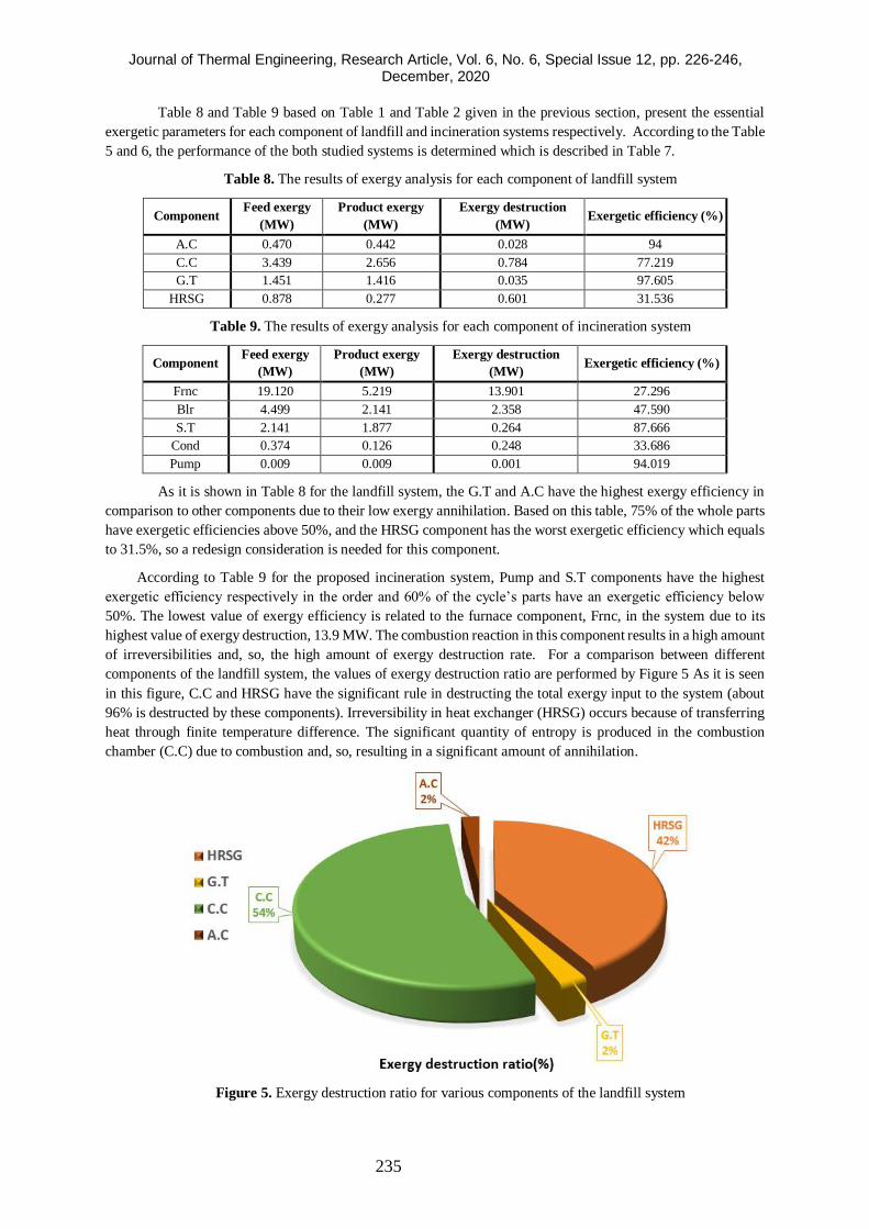
of irreversibilities and, so, the high amount of exergy destruction rate. For a comparison between different
components of the landfill system, the values of exergy destruction ratio are performed by Figure 5 As it is seen
in this figure, C.C and HRSG have the significant rule in destructing the total exergy input to the system (about
96% is destructed by these components). Irreversibility in heat exchanger (HRSG) occurs because of transferring
heat through finite temperature difference. The significant quantity of entropy is produced in the combustion
chamber (C.C) due to combustion and, so, resulting in a significant amount of annihilation.
Figure 5. Exergy destruction ratio for various components of the landfill system
Journal of Thermal Engineering, Research Article, Vol. 6, No. 6, Special Issue 12, pp. 226-246, December, 2020
236
Figure 6 shows the exergy destruction ratio of various components for the incineration system. The exergy
destruction ratio value is the most for the French among the other ingredients (83% approximately). The main
reason of irreversibility in the furnace, Frnc, component is related to the chemical reaction; Therefore, a notable
reduction in exergy destruction cannot be expected. Still reducing the air-fuel ratio and preheating the combustion
air are proposals for improving the performance of the mentioned component. Also, it is realized from this figure
that the Pump component has the lowest value of exergy destruction ratio in the system because of its small
consumed power.
Figure 6. Exergy destruction ratio for components of the incineration system
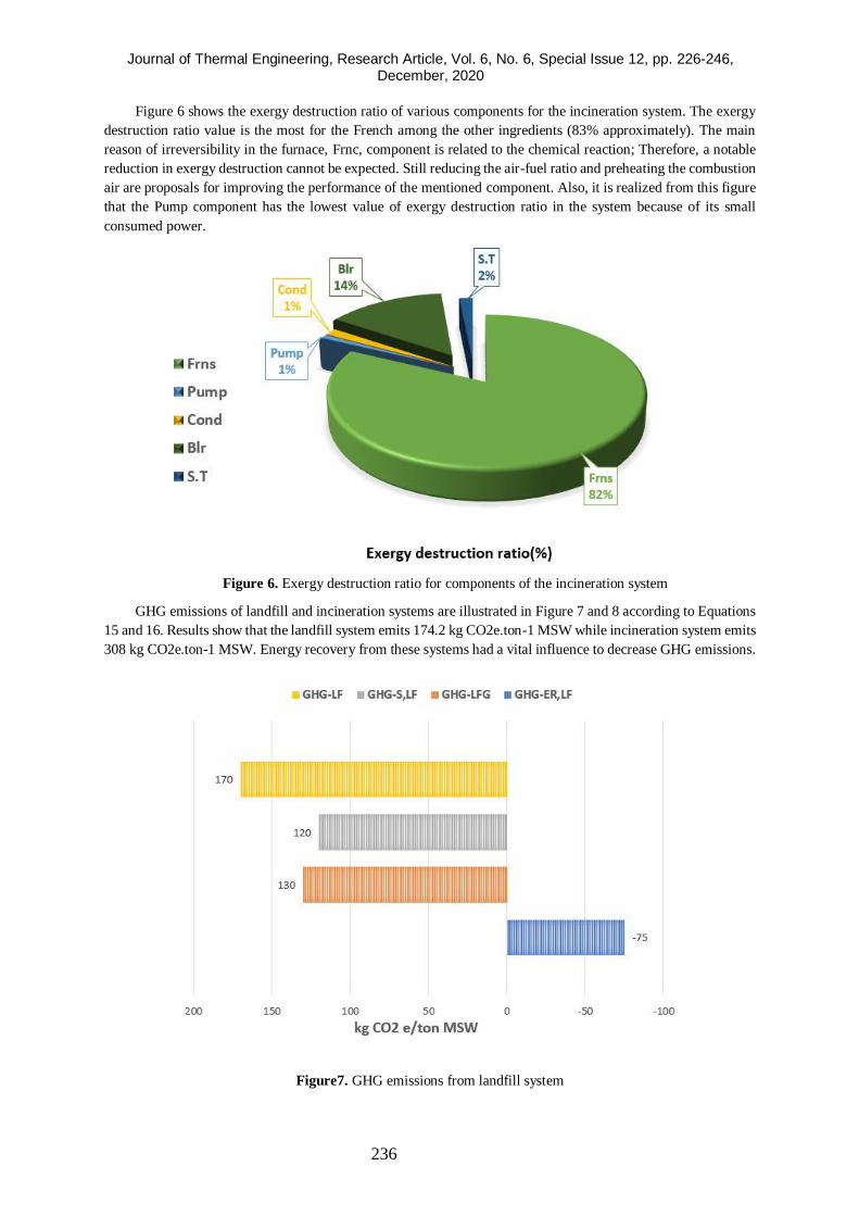
GHG emissions of landfill and incineration systems are illustrated in Figure 7 and 8 according to Equations
15 and 16. Results show that the landfill system emits 174.2 kg CO2e.ton-1 MSW while incineration system emits
308 kg CO2e.ton-1 MSW. Energy recovery from these systems had a vital influence to decrease GHG emissions.
Figure7. GHG emissions from landfill system
Journal of Thermal Engineering, Research Article, Vol. 6, No. 6, Special Issue 12, pp. 226-246, December, 2020
237
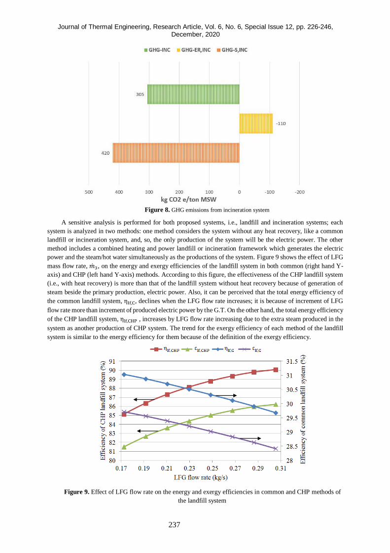
Figure 8. GHG emissions from incineration system
A sensitive analysis is performed for both proposed systems, i.e., landfill and incineration systems; each
system is analyzed in two methods: one method considers the system without any heat recovery, like a common
landfill or incineration system, and, so, the only production of the system will be the electric power. The other
method includes a combined heating and power landfill or incineration framework which generates the electric
power and the steam/hot water simultaneously as the productions of the system. Figure 9 shows the effect of LFG
mass flow rate, ��3, on the energy and exergy efficiencies of the landfill system in both common (right hand Y-
axis) and CHP (left hand Y-axis) methods. According to this figure, the effectiveness of the CHP landfill system
(i.e., with heat recovery) is more than that of the landfill system without heat recovery because of generation of
steam beside the primary production, electric power. Also, it can be perceived that the total energy efficiency of
the common landfill system, ηIf,C, declines when the LFG flow rate increases; it is because of increment of LFG
flow rate more than increment of produced electric power by the G.T. On the other hand, the total energy efficiency
of the CHP landfill system, ηlf,CHP , increases by LFG flow rate increasing due to the extra steam produced in the
system as another production of CHP system. The trend for the exergy efficiency of each method of the landfill
system is similar to the energy efficiency for them because of the definition of the exergy efficiency.
Figure 9. Effect of LFG flow rate on the energy and exergy efficiencies in common and CHP methods of
the landfill system
Journal of Thermal Engineering, Research Article, Vol. 6, No. 6, Special Issue 12, pp. 226-246, December, 2020
238
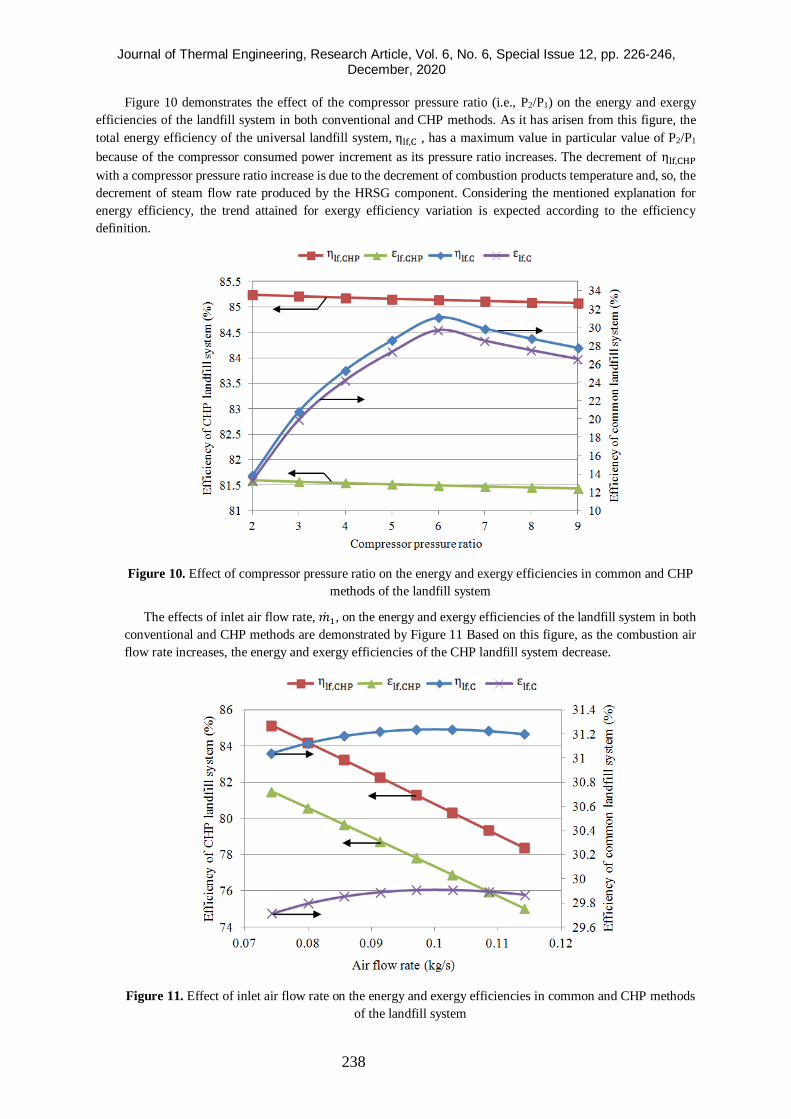
Figure 10 demonstrates the effect of the compressor pressure ratio (i.e., P2/P1) on the energy and exergy
efficiencies of the landfill system in both conventional and CHP methods. As it has arisen from this figure, the
total energy efficiency of the universal landfill system, ηlf,C , has a maximum value in particular value of P2/P1
because of the compressor consumed power increment as its pressure ratio increases. The decrement of ηlf,CHP
with a compressor pressure ratio increase is due to the decrement of combustion products temperature and, so, the
decrement of steam flow rate produced by the HRSG component. Considering the mentioned explanation for
energy efficiency, the trend attained for exergy efficiency variation is expected according to the efficiency
definition.
Figure 10. Effect of compressor pressure ratio on the energy and exergy efficiencies in common and CHP
methods of the landfill system
The effects of inlet air flow rate, ��1, on the energy and exergy efficiencies of the landfill system in both
conventional and CHP methods are demonstrated by Figure 11 Based on this figure, as the combustion air
flow rate increases, the energy and exergy efficiencies of the CHP landfill system decrease.
Figure 11. Effect of inlet air flow rate on the energy and exergy efficiencies in common and CHP methods
of the landfill system
Journal of Thermal Engineering, Research Article, Vol. 6, No. 6, Special Issue 12, pp. 226-246, December, 2020
239
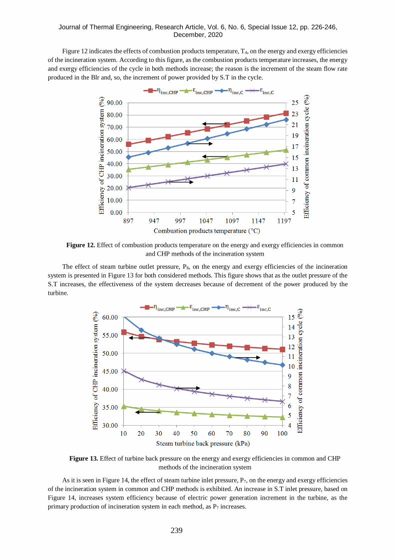
Figure 12 indicates the effects of combustion products temperature, T4, on the energy and exergy efficiencies
of the incineration system. According to this figure, as the combustion products temperature increases, the energy
and exergy efficiencies of the cycle in both methods increase; the reason is the increment of the steam flow rate
produced in the Blr and, so, the increment of power provided by S.T in the cycle.
Figure 12. Effect of combustion products temperature on the energy and exergy efficiencies in common
and CHP methods of the incineration system
The effect of steam turbine outlet pressure, P8, on the energy and exergy efficiencies of the incineration
system is presented in Figure 13 for both considered methods. This figure shows that as the outlet pressure of the
S.T increases, the effectiveness of the system decreases because of decrement of the power produced by the
turbine.
Figure 13. Effect of turbine back pressure on the energy and exergy efficiencies in common and CHP
methods of the incineration system
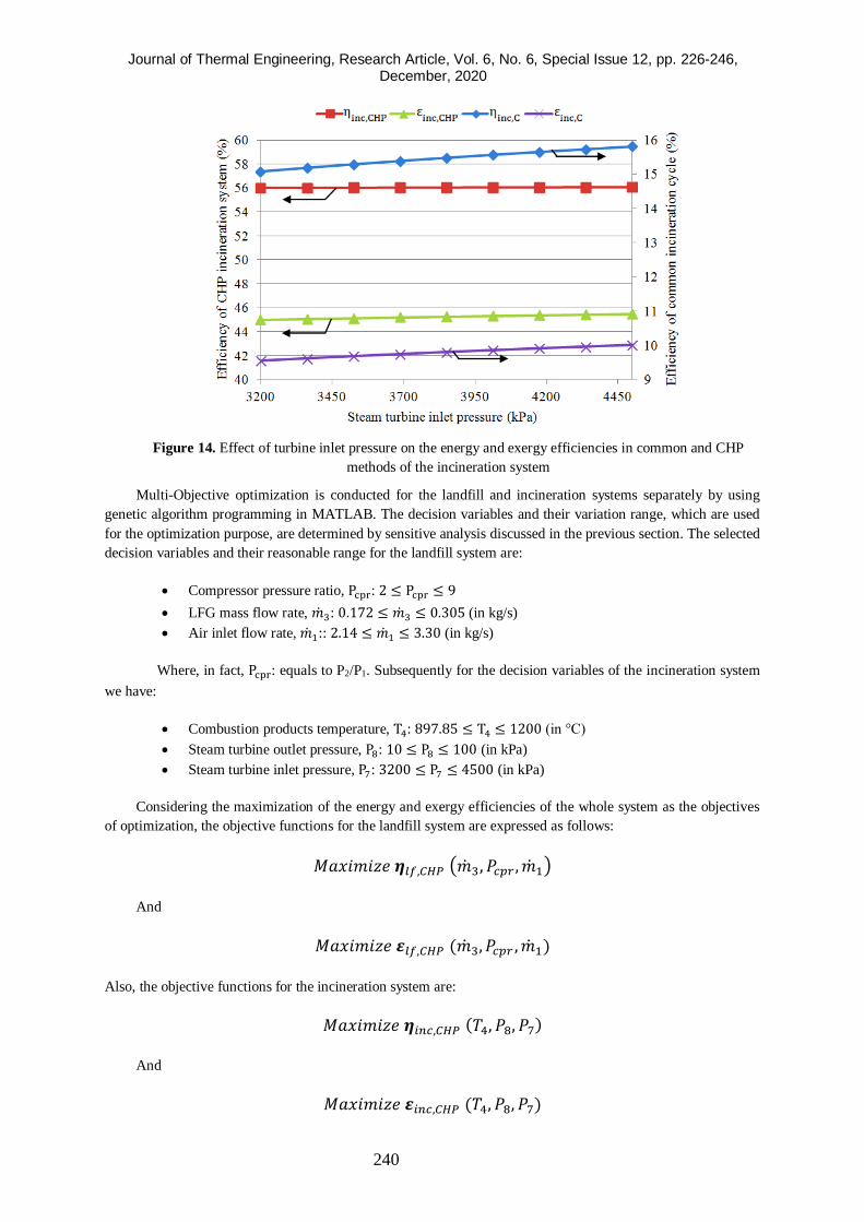
As it is seen in Figure 14, the effect of steam turbine inlet pressure, P7, on the energy and exergy efficiencies
of the incineration system in common and CHP methods is exhibited. An increase in S.T inlet pressure, based on
Figure 14, increases system efficiency because of electric power generation increment in the turbine, as the
primary production of incineration system in each method, as P7 increases.
Journal of Thermal Engineering, Research Article, Vol. 6, No. 6, Special Issue 12, pp. 226-246, December, 2020
240
Figure 14. Effect of turbine inlet pressure on the energy and exergy efficiencies in common and CHP
methods of the incineration system
Multi-Objective optimization is conducted for the landfill and incineration systems separately by using
genetic algorithm programming in MATLAB. The decision variables and their variation range, which are used
for the optimization purpose, are determined by sensitive analysis discussed in the previous section. The selected
decision variables and their reasonable range for the landfill system are:
• Compressor pressure ratio, Pcpr: 2 ≤ Pcpr ≤ 9
• LFG mass flow rate, ��3: 0.172 ≤ ��3 ≤ 0.305 (in kg/s)
• Air inlet flow rate, ��1:: 2.14 ≤ ��1 ≤ 3.30 (in kg/s)
Where, in fact, Pcpr: equals to P2/P1. Subsequently for the decision variables of the incineration system
we have:
• Combustion products temperature, T4: 897.85 ≤ T4 ≤ 1200 (in °C)
• Steam turbine outlet pressure, P8: 10 ≤ P8 ≤ 100 (in kPa)
• Steam turbine inlet pressure, P7: 3200 ≤ P7 ≤ 4500 (in kPa)
Considering the maximization of the energy and exergy efficiencies of the whole system as the objectives
of optimization, the objective functions for the landfill system are expressed as follows:
𝑀𝑎𝑥𝑖𝑚𝑖𝑧𝑒 𝜼𝑙𝑓,𝐶𝐻𝑃 (��3, 𝑃𝑐𝑝𝑟 , ��1)
And
𝑀𝑎𝑥𝑖𝑚𝑖𝑧𝑒 𝜺𝑙𝑓,𝐶𝐻𝑃 (��3, 𝑃𝑐𝑝𝑟 , ��1)
Also, the objective functions for the incineration system are:
𝑀𝑎𝑥𝑖𝑚𝑖𝑧𝑒 𝜼𝑖𝑛𝑐,𝐶𝐻𝑃 (𝑇4, 𝑃8, 𝑃7)
And
𝑀𝑎𝑥𝑖𝑚𝑖𝑧𝑒 𝜺𝑖𝑛𝑐,𝐶𝐻𝑃 (𝑇4, 𝑃8, 𝑃7)
Journal of Thermal Engineering, Research Article, Vol. 6, No. 6, Special Issue 12, pp. 226-246, December, 2020
241
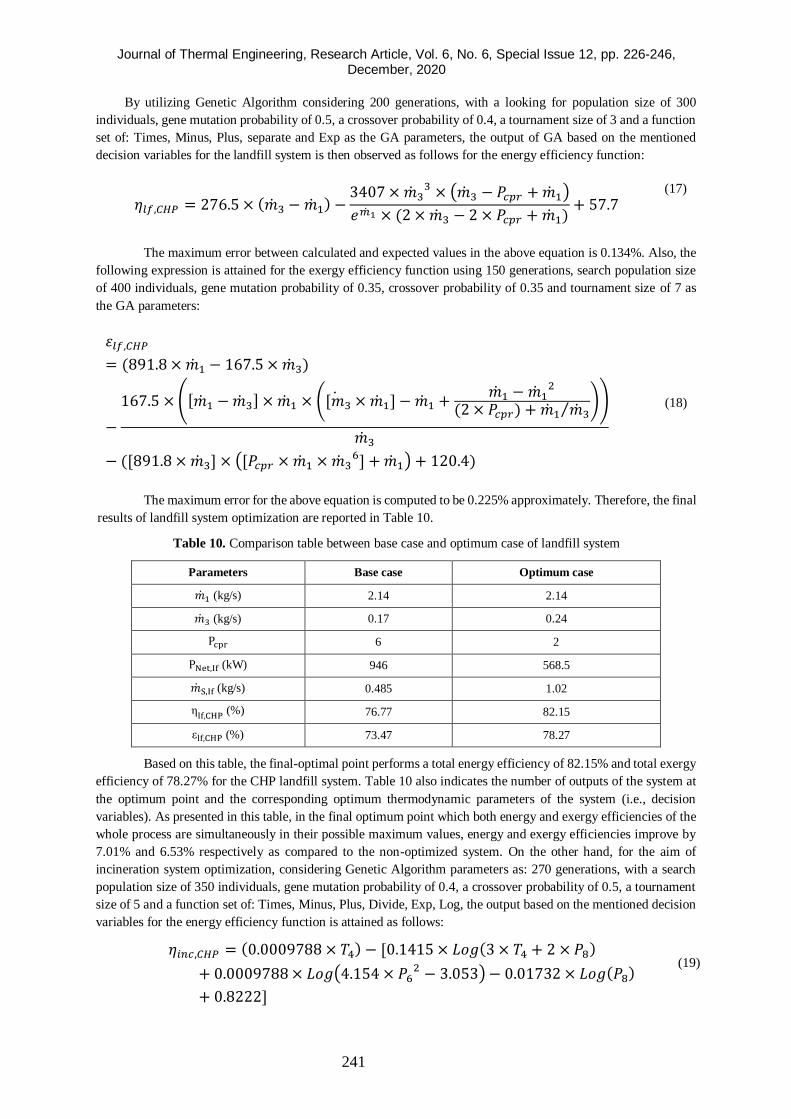
By utilizing Genetic Algorithm considering 200 generations, with a looking for population size of 300
individuals, gene mutation probability of 0.5, a crossover probability of 0.4, a tournament size of 3 and a function
set of: Times, Minus, Plus, separate and Exp as the GA parameters, the output of GA based on the mentioned
decision variables for the landfill system is then observed as follows for the energy efficiency function:
𝜂𝑙𝑓,𝐶𝐻𝑃 = 276.5 × (��3 − ��1) −3407 × ��3
3 × (��3 − 𝑃𝑐𝑝𝑟 + ��1)
𝑒��1 × (2 × ��3 − 2 × 𝑃𝑐𝑝𝑟 + ��1)+ 57.7
(17)
The maximum error between calculated and expected values in the above equation is 0.134%. Also, the
following expression is attained for the exergy efficiency function using 150 generations, search population size
of 400 individuals, gene mutation probability of 0.35, crossover probability of 0.35 and tournament size of 7 as
the GA parameters:
𝜀𝑙𝑓,𝐶𝐻𝑃
= (891.8 × ��1 − 167.5 × ��3)
−
167.5 × ([��1 − ��3] × ��1 × ([��3 × ��1] − ��1 +��1 − ��1
2
(2 × 𝑃𝑐𝑝𝑟) + ��1 ��3⁄ ))
��3
− ([891.8 × ��3] × ([𝑃𝑐𝑝𝑟 × ��1 × ��36] + ��1) + 120.4)
(18)
The maximum error for the above equation is computed to be 0.225% approximately. Therefore, the final
results of landfill system optimization are reported in Table 10.
Table 10. Comparison table between base case and optimum case of landfill system
Parameters Base case Optimum case
��1 (kg/s) 2.14 2.14
��3 (kg/s) 0.17 0.24
Pcpr 6 2
PNet,If (kW) 946 568.5
��S,If (kg/s) 0.485 1.02
ηlf,CHP
(%) 76.77 82.15
εlf,CHP (%) 73.47 78.27
Based on this table, the final-optimal point performs a total energy efficiency of 82.15% and total exergy
efficiency of 78.27% for the CHP landfill system. Table 10 also indicates the number of outputs of the system at
the optimum point and the corresponding optimum thermodynamic parameters of the system (i.e., decision
variables). As presented in this table, in the final optimum point which both energy and exergy efficiencies of the
whole process are simultaneously in their possible maximum values, energy and exergy efficiencies improve by
7.01% and 6.53% respectively as compared to the non-optimized system. On the other hand, for the aim of
incineration system optimization, considering Genetic Algorithm parameters as: 270 generations, with a search
population size of 350 individuals, gene mutation probability of 0.4, a crossover probability of 0.5, a tournament
size of 5 and a function set of: Times, Minus, Plus, Divide, Exp, Log, the output based on the mentioned decision
variables for the energy efficiency function is attained as follows:
𝜂𝑖𝑛𝑐,𝐶𝐻𝑃 = (0.0009788 × 𝑇4) − [0.1415 × 𝐿𝑜𝑔(3 × 𝑇4 + 2 × 𝑃8)
+ 0.0009788 × 𝐿𝑜𝑔(4.154 × 𝑃62 − 3.053) − 0.01732 × 𝐿𝑜𝑔(𝑃8)
+ 0.8222]
(19)
Journal of Thermal Engineering, Research Article, Vol. 6, No. 6, Special Issue 12, pp. 226-246, December, 2020
242
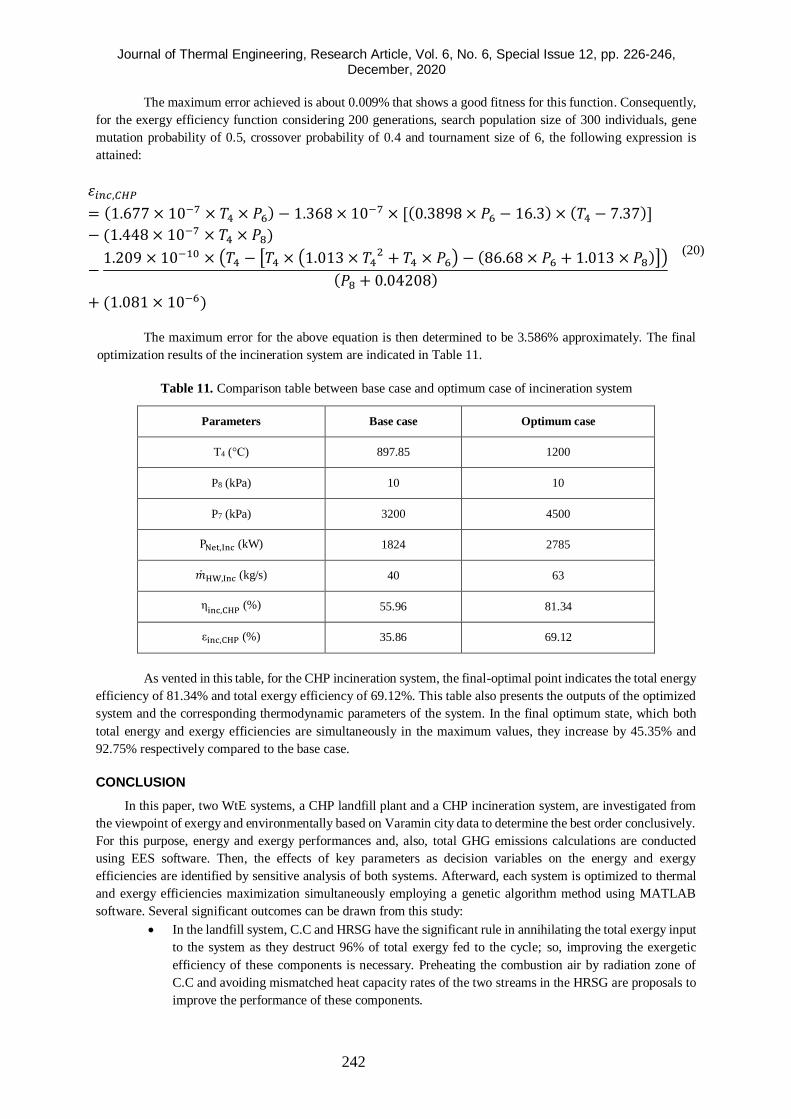
The maximum error achieved is about 0.009% that shows a good fitness for this function. Consequently,
for the exergy efficiency function considering 200 generations, search population size of 300 individuals, gene
mutation probability of 0.5, crossover probability of 0.4 and tournament size of 6, the following expression is
attained:
𝜀𝑖𝑛𝑐,𝐶𝐻𝑃
= (1.677 × 10⁻⁷ × 𝑇4 × 𝑃6) − 1.368 × 10⁻⁷ × [(0.3898 × 𝑃6 − 16.3) × (𝑇4 − 7.37)]
− (1.448 × 10⁻⁷ × 𝑇4 × 𝑃8)
−1.209 × 10⁻¹⁰ × (𝑇4 − [𝑇4 × (1.013 × 𝑇4
2 + 𝑇4 × 𝑃6) − (86.68 × 𝑃6 + 1.013 × 𝑃8)])
(𝑃8 + 0.04208)
+ (1.081 × 10⁻⁶)
(20)
The maximum error for the above equation is then determined to be 3.586% approximately. The final
optimization results of the incineration system are indicated in Table 11.
Table 11. Comparison table between base case and optimum case of incineration system
Parameters Base case Optimum case
T4 (°C) 897.85 1200
P8 (kPa) 10 10
P7 (kPa) 3200 4500
PNet,Inc (kW) 1824 2785
��HW,Inc (kg/s) 40 63
ηinc,CHP
(%) 55.96 81.34
εinc,CHP (%) 35.86 69.12
As vented in this table, for the CHP incineration system, the final-optimal point indicates the total energy
efficiency of 81.34% and total exergy efficiency of 69.12%. This table also presents the outputs of the optimized
system and the corresponding thermodynamic parameters of the system. In the final optimum state, which both
total energy and exergy efficiencies are simultaneously in the maximum values, they increase by 45.35% and
92.75% respectively compared to the base case.
CONCLUSION
In this paper, two WtE systems, a CHP landfill plant and a CHP incineration system, are investigated from
the viewpoint of exergy and environmentally based on Varamin city data to determine the best order conclusively.
For this purpose, energy and exergy performances and, also, total GHG emissions calculations are conducted
using EES software. Then, the effects of key parameters as decision variables on the energy and exergy
efficiencies are identified by sensitive analysis of both systems. Afterward, each system is optimized to thermal
and exergy efficiencies maximization simultaneously employing a genetic algorithm method using MATLAB
software. Several significant outcomes can be drawn from this study:
• In the landfill system, C.C and HRSG have the significant rule in annihilating the total exergy input
to the system as they destruct 96% of total exergy fed to the cycle; so, improving the exergetic
efficiency of these components is necessary. Preheating the combustion air by radiation zone of
C.C and avoiding mismatched heat capacity rates of the two streams in the HRSG are proposals to
improve the performance of these components.
Journal of Thermal Engineering, Research Article, Vol. 6, No. 6, Special Issue 12, pp. 226-246, December, 2020
243
• The exergy annihilation ratio is the most for the French in the incineration framework among the
other components. Reducing the air-fuel ratio and preheating the combustion air can decrease the
irreversibilities of chemical reaction occurred in France and, so, improve the performance of the
mentioned component.
• Environmental analysis based on GHG emissions shows that landfill system emitted less GHG than
incineration system. Increment of recovery rate for LFG in landfill system and improvement of
electricity and heat production and, so, energy and exergy efficiencies in both systems can reduce
the GHG emissions.
• An increase in LFG flow rate of CHP landfill system causes an increase in the total energy and
exergy efficiencies of the system. Also, as the combustion products temperature climb, the energy
and exergy efficiencies of the CHP incineration system increase.
• The multi-objective optimization of the landfill system utilizing GA performs 7.01% and 6.53%
improvement in total energy and exergy efficiencies respectively as compared to a non-optimized
system. Additionally, the overall electric power produced is diminished by 39.90%, and the steam
production is extremely enhanced by 110.31% at the optimum conditions.
• For the incineration system, the multi-objective optimization using GA indicates a significant
improvement of 45.35% and 92.75% in total energy and exergy efficiencies respectively as
compared to the base system. Moreover, the net electric power and the hot water produced are
improved by 52.69% and 57.50% at the optimal-point of the system.
• Finally, according to the lower GHG emissions and higher energy and exergy efficiencies achieved
by landfill system, using the proposed CHP landfill plant is energetically and environmentally more
appropriate than using the incineration plant for Varamin city.
NOMENCLATURE
ε Exergy efficiency (%)
η Energy efficiency (%)
h Specific enthalpy (kJ/kg)/hour
ṁ Mass flow rate (kg/s)
Q Heat rate (kW)
R Gas constant (kJ/kg-K)
s Specific entropy (kJ/kg-K)
T Temperature (°C or K)
X Exergy (kW)
x Specific exergy (kW/kg)
y Mole fraction
W Power (kW)
G Giga
J joule
k Component/stream/kilo
SUBSCRIPTS
0 Ambient/Dead state
1, 2, 3,… Cycle locations
D Destruction
F Feed exergy
Journal of Thermal Engineering, Research Article, Vol. 6, No. 6, Special Issue 12, pp. 226-246, December, 2020
244
f Fuel
i Inlet
j Component in mixture
k Component in cycle
o Outlet
P Product exergy
Q Boundary heat transferring
S Steam/Stack
W Boundary mechanical work
g Gram
M Mega
ABBREVIATION
GHG Greenhouse gas emission parameter (kg of CO2e/ton of MSW)
LHV Low heating value parameter (kJ/kg)
A.C Air compressor
Blr Boiler
C.C Combustion chamber
CH Chemical
CHP Combined heating and power
Cond Condenser
ER Electricity
Frnc Furnace
G.T Gas turbine
HRSG Heat recovery steam generator
HW Hot water
Inc Incineration
Lf Landfill
LFG Landfill gas
mthn Methane
PH Physical
S.T Steam turbine
SW Solid waste
Tot total
Net Network
EES Engineering equation solver
KN Kinetic
PT Potential
Journal of Thermal Engineering, Research Article, Vol. 6, No. 6, Special Issue 12, pp. 226-246, December, 2020
245
REFERENCES
[1] Tumen Ozdil NF, Pekdur A. Energy and exergy assessment of a cogeneration system in food industry: A
case study. Int J Exergy 2016. doi:10.1504/IJEX.2016.076866.
[2] Tumen Ozdil NF, Tantekin A, Erbay Z. Energy and exergy analyses of a fluidized bed coal combustor
steam plant in textile industry. Fuel 2016. doi:10.1016/j.fuel.2016.06.091.
[3] Özdil NF, Tantekin A, Pekdur A. Performance assessment of a cogeneration system in food industry. J
Therm Eng 2018. doi:10.18186/journal-of-thermal-engineering.382412.
[4] Tantekin A, Özdil NF. Thermodynamic analysis of a fluidized bed coal combustor steam plant in textile
industry. J Therm Eng 2017. doi:10.18186/journal-of-thermal-engineering.353690.
[5] Tumen Ozdil NF, Tantekin A. Exergy and exergoeconomic assessments of an electricity production
system in a running wastewater treatment plant. Renew Energy 2016. doi:10.1016/j.renene.2016.05.039.
[6] Ghaebi H, Abbaspour G. Performance analysis and thermodynamic modeling of a poly generation system
by integrating a multi-effect-desalination thermo-vapor compression (MED-TVC) system with a
combined cooling, heating and power (CCHP) system. J Therm Eng 2018. doi:10.18186/journal-of-
thermal-engineering.410264.
[7] Thornley P, Upham P, Huang Y, Rezvani S, Brammer J, Rogers J. Integrated assessment of bioelectricity
technology options. Energy Policy 2009. doi:10.1016/j.enpol.2008.10.032.
[8] Bove R, Lunghi P. Electric power generation from landfill gas using traditional and innovative
technologies. Energy Convers Manag 2006. doi:10.1016/j.enconman.2005.08.017.
[9] Sun L, Fujii M, Tasaki T, Dong H, Ohnishi S. Improving waste to energy rate by promoting an integrated
municipal solid-waste management system. Resour Conserv Recycl 2018.
doi:10.1016/j.resconrec.2018.05.005.
[10] Xydis G, Nanaki E, Koroneos C. Exergy analysis of biogas production from a municipal solid waste
landfill. Sustain Energy Technol Assessments 2013. doi:10.1016/j.seta.2013.08.003.
[11] Trindade AB, Carlos J, Palacio E, González AM, Rúa Orozco DJ, Silva Lora EE, et al. Advanced exergy
analysis and environmental assesment of the steam cycle of an incineration system of municipal solid
waste with energy recovery. Energy Convers Manag 2018.
[12] Azami S, Taheri M, Pourali O, Torabi F. Energy and exergy analyses of a mass-fired boiler for a proposed
waste-to-energy power plant in Tehran. Appl Therm Eng 2018.
doi:10.1016/j.applthermaleng.2018.05.045.
[13] Leckner B. Process aspects in combustion and gasification Waste-to-Energy (WtE) units. Waste Manag
2015. doi:10.1016/j.wasman.2014.04.019.
[14] Lombardi L, Carnevale E, Corti A. A review of technologies and performances of thermal treatment
systems for energy recovery from waste. Waste Manag 2015. doi:10.1016/j.wasman.2014.11.010.
[15] Hong J, Li X, Zhaojie C. Life cycle assessment of four municipal solid waste management scenarios in
China. Waste Manag 2010. doi:10.1016/j.wasman.2010.03.038.
[16] Damgaard A, Riber C, Fruergaard T, Hulgaard T, Christensen TH. Life-cycle-assessment of the historical
development of air pollution control and energy recovery in waste incineration. Waste Manag 2010.
doi:10.1016/j.wasman.2010.03.025.
[17] Hessami MA. Specific applications of bio/landfill gas produced from waste organic material. Renew
Energy 1994. doi:10.1016/0960-1481(94)90099-X.
[18] Raj NT, Iniyan S, Goic R. A review of renewable energy based cogeneration technologies. Renew Sustain
Energy Rev 2011. doi:10.1016/j.rser.2011.06.003.
[19] Murphy JD, McKeogh E. Technical, economic and environmental analysis of energy production from
municipal solid waste. Renew Energy 2004. doi:10.1016/j.renene.2003.12.002.
[20] EES. Software n.d. http://www.fchart.com/ees/.
[21] Houck CR, Joines JA, Key MG. A Genetic Algorithm for Function Optimization: A Matlab
Implementation. 1995.
[22] Smith JM. Introduction to chemical engineering thermodynamics. J Chem Educ 1950.
Journal of Thermal Engineering, Research Article, Vol. 6, No. 6, Special Issue 12, pp. 226-246, December, 2020
246
doi:10.1021/ed027p584.3.
[23] Ghasemi A, Heidarnejad P, Noorpoor A. A novel solar-biomass based multi-generation energy system
including water desalination and liquefaction of natural gas system: Thermodynamic and thermoeconomic
optimization. J Clean Prod 2018. doi:10.1016/j.jclepro.2018.05.160.
[24] Kotas TJ. Exergy analysis of simple processes. Exergy Method Therm. Plant Anal., 1985.
doi:10.1016/b978-0-408-01350-5.50011-8.
[25] Noorpoor A, Heidarnejad P, Hashemian N, Ghasemi A. A thermodynamic model for exergetic
performance and optimization of a solar and biomass-fuelled multigeneration system. Energy Equip Syst
2016. doi:10.22059/ees.2016.23044.
[26] Dincer I, Rosen MA. Energy, environment and sustainable development. Appl. Energy, 1999.
doi:10.1016/S0306-2619(99)00111-7.
[27] Seshadri K. Thermal design and optimization. vol. 21. 1996. doi:10.1016/s0360-5442(96)90000-6.
[28] Kaviri AG, Jaafar MNM, Lazim TM. Modeling and multi-objective exergy based optimization of a
combined cycle power plant using a genetic algorithm. Energy Convers Manag 2012.
doi:10.1016/j.enconman.2012.01.002.
[29] Baghernejad A, Yaghoubi M. Exergoeconomic analysis and optimization of an Integrated Solar
Combined Cycle System (ISCCS) using genetic algorithm. Energy Convers Manag 2011.
doi:10.1016/j.enconman.2010.12.019.
[30] Ghasemi A, Hashemian N, Noorpoor A, Heidarnejad P. Exergy based optimization of a biomass and solar
fuelled cchp hybrid seawater desalination plant. J Therm Eng 2017. doi:10.18186/thermal.290251.
[31] Ameri M, Mokhtari H, Mostafavi Sani M. 4E analyses and multi-objective optimization of different fuels
application for a large combined cycle power plant. Energy 2018. doi:10.1016/j.energy.2018.05.039.
[32] Golkar B, Naserabad SN, Soleimany F, Dodange M, Ghasemi A, Mokhtari H, et al. Determination of
optimum hybrid cooling wet/dry parameters and control system in off design condition: Case study. Appl
Therm Eng 2019;149:132–50. doi:10.1016/j.applthermaleng.2018.12.017.
[33] Cao Y, Nikafshan Rad H, Hamedi Jamali D, Hashemian N, Ghasemi A. A novel multi-objective spiral
optimization algorithm for an innovative solar/biomass-based multi-generation energy system: 3E
analyses, and optimization algorithms comparison. Energy Convers Manag 2020;219:112961.
doi:10.1016/j.enconman.2020.112961.
[34] Woon KS, Lo IMC. Greenhouse gas accounting of the proposed landfill extension and advanced
incineration facility for municipal solid waste management in Hong Kong. Sci Total Environ 2013.
doi:10.1016/j.scitotenv.2013.04.061.
[35] Wanichpongpan W, Gheewala SH. Life cycle assessment as a decision support tool for landfill gas-to
energy projects. J Clean Prod 2007. doi:10.1016/j.jclepro.2006.06.008.
[36] https://www.epa.gov/air-emissions-factors-and-quantification/emissions-estimation-tools/2017.08 2017.
[37] http://pasmandvaramin.ir/2017.08 2017.