Embed Size (px)
Citation preview
General rights Copyright and moral rights for the publications made accessible in the public portal are retained by the authors and/or other copyright owners and it is a condition of accessing publications that users recognise and abide by the legal requirements associated with these rights.
Users may download and print one copy of any publication from the public portal for the purpose of private study or research.
You may not further distribute the material or use it for any profit-making activity or commercial gain
You may freely distribute the URL identifying the publication in the public portal If you believe that this document breaches copyright please contact us providing details, and we will remove access to the work immediately and investigate your claim.
Downloaded from orbit.dtu.dk on: Mar 31, 2020
Thermodynamic analysis of small-scale dimethyl ether (DME) and methanol plantsbased on the efficient two-stage gasifier
Clausen, Lasse Røngaard; Elmegaard, Brian; Ahrenfeldt, Jesper; Henriksen, Ulrik Birk
Published in:Energy
Link to article, DOI:10.1016/j.energy.2011.08.047
Publication date:2011
Document VersionPeer reviewed version
Link back to DTU Orbit
Citation (APA):Clausen, L. R., Elmegaard, B., Ahrenfeldt, J., & Henriksen, U. B. (2011). Thermodynamic analysis of small-scaledimethyl ether (DME) and methanol plants based on the efficient two-stage gasifier. Energy, 36(10), 5805-5814.https://doi.org/10.1016/j.energy.2011.08.047

THERMODYNAMIC ANALYSIS OF SMALL-SCALE DIMETHYL ETHER (DME) AND METHANOL PLANTS BASED ON THE EFFICIENT TWO-STAGE GASIFIER Lasse R. Clausen a, *, Brian Elmegaard a, Jesper Ahrenfeldt b, Ulrik Henriksen b a Section of Thermal Energy Systems, Department of Mechanical Engineering, The Technical University of Denmark (DTU), Nils Koppels Allé Bld. 403, DK-2800 Kgs. Lyngby, Denmark b Biosystems Division, Risø National Laboratory for Sustainable Energy, The Technical University of Denmark (DTU), Frederiksborgvej 399, DK-4000 Roskilde, Denmark
Received: xx Abstract Models of DME and methanol synthesis plants have been designed by combining the features of the simulation tools DNA and Aspen Plus. The plants produce DME or methanol by catalytic conversion of a syngas generated by gasification of woody biomass. Electricity is co-produced in the plants by a gas engine utilizing the unconverted syngas. A two-stage gasifier with a cold gas efficiency of 93% is used, but because of the design of this type of gasifier, the plants have to be of small scale (5 MWth biomass input). The plant models show energy efficiencies from biomass to DME/methanol + electricity of 51-58% (LHV), which shows to be 6-8%-points lower than efficiencies achievable on large-scale plants based on torrefied biomass pellets. By using waste heat from the plants for district heating, the total energy efficiencies become 87-88%. Keywords: biorefinery, dimethyl ether, DME, methanol, Two-Stage Gasifier, syngas. 1. Introduction The CO2 emissions of the transportation sector can be reduced by increasing the use of biofuels – especially when the biofuels are produced from lignocellulosic biomass [1]. Dimethyl ether (DME) and methanol are two such biofuels. DME is a diesel-like fuel that can be produced from biomass in processes very similar to methanol production processes. Combustion of DME produces lower emissions of NOx than combustion of diesel, with no particulate matter or SOx in the flue gas [2], however it also requires storage pressures in excess of 5 bar to maintain a liquid state, which is similar to liquefied petroleum gas (LPG). Two DME and two methanol synthesis plant, based on syngas from gasification of wood chips, are investigated in this paper: • The DME-OT and MeOH-OT plants uses once-through (OT) synthesis and the unconverted
syngas is combusted in a gas engine to produce electricity. • The DME-RC and MeOH-RC plants use recycling of some of the unconverted syngas to the
DME/methanol reactor to maximize DME/methanol production. All the electricity produced by the gas engine is used on-site.
Production of methanol from biomass is very well investigated in the literature (e.g., [3,4]), and DME production from biomass has also been reported in the literature (e.g., [5,6]). Small-scale tri-generation of liquid fuel, electricity and heat based on an efficient two-stage gasifier has however not been presented in the literature. The small-scale production enables the use of the energy efficient Two-Stage Gasifier [7,8] and enhances the possibility of utilizing a district heating co-production. The economy of small-scale production of liquid fuel cannot compete with large-scale
* Corresponding author. Fax: +45 45884325, email: [email protected] 1

production [9,10]1, but the co-production of district heating in the small-scale plants could improve the economy of the small-scale plants. This paper documents the design of two DME and two methanol plants using the modeling tool DNA [11,12] for the steam dryer and gasifier modeling and Aspen Plus for the downstream modeling. Thermodynamic performance of the plant configurations are presented and compared with the performance of large-scale plants. 2. Design of the DME and methanol plants A simplified process flow sheet of the DME and methanol plant designs is shown in Fig. 1 and detailed process flow sheets can be seen in Fig. 3-Fig. 6. Plant design aspects related to feedstock preparation, gasification, syngas conditioning, DME/methanol synthesis and separation are described next and are followed by a discussion of electricity and heat production in the plants. Important process design parameters used in the modeling are shown in Table 1. Steam drying The wet wood chips are dried in co-flow with superheated steam by using a screw conveyer design. The methanol/DME reactor and the gas engine exhaust supply the heat needed to superheat the steam. Gasification A two-stage gasifier at atmospheric pressure is used for gasifying the dried wood chips. The gasifier is an updated design of the one described in [7,8]. In the first stage, the dried wood chips, together with the steam surplus from the steam dryer, are heated/pyrolyzed in a closed screw conveyer by passing the hot syngas from the gasifier on the outside surface of the closed screw conveyer2. In order to lower the tar content, the pyrolysis gas is partially oxidized by adding air. In the second stage, the partially oxidized gas passes through a downdraft fixed bed, where the gasification reactions occur. The bed consists of coke from the pyrolysis stage. After this stage, the tar content in the gas is almost zero [7]3. The composition of the syngas is calculated by assuming chemical equilibrium at a temperature slightly above the gasifier exit temperature4. In the methanol plants the H2/CO ratio of the syngas is set to 2 by adjusting the biomass water content (42.5 mass% water), and in the DME plants the H2/CO ratio is reduced to 1.5 by removing steam from the steam dryer loop. A H2/CO ratio of 1 is optimal for DME synthesis (Eq. 4) [5], but a ratio of 1.5 is estimated to be the lowest achievable ratio that the gasifier can produce, due to soot formation in the partial oxidation at lower steam contents. The two-stage gasification concept has been demonstrated in plants with 75 kWth [7] and 700 kWth biomass input. Because of the design of the pyrolysis stage (heat is transferred from gas to solid), it is not considered possible to scale up the gasifier to more than some MWth [8]5. Therefore, the biomass input for the modeled gasifier is set to 5 MWth (dry).
1 Small-scale plants will have lower biomass transportation cost than large-scale plants, but economy of scale more than outweighs this. 2 The heat consumption in the pyrolysis unit for the pyrolysis of dry wood is calculated based on measured temperatures of inputs and outputs and measured syngas composition – the heat loss to the surroundings is not included. The heat consumption for pyrolysis of dry wood (0% water) was estimated to be 952 kJ/kg-(dry wood) or 5.2% of the LHV (heating from 115°C to 630°C). 3 Only naphthalene could be measured and the content was <0.1 mg/Nm3 [7]. 4 In order to match measured data for the methane content, the model adds 0.67 mole% to the methane content calculated by chemical equilibrium. 5 The reference states a size of 3-10 MWth biomass input.
2

Gas cleaning Gas cleaning of biomass syngas for DME/methanol synthesis includes cyclones and filters for particle removal, a water wash to remove NH3 and HCl, and guard beds placed just before the synthesis reactor to remove sulfur and other impurities [13,14]. The guard beds consist of ZnO filters to remove H2S, and active carbon filters to remove traces of NH3, HCl, HCN, CS2, and COS [14]. Guard beds are used to remove sulfur because the sulfur content in biomass syngas is very low6. Measurements on a two-stage gasifier with 75 kWth input showed only 0.93 ppm of COS and 0.5-1 ppm of H2S in the raw gas [15]. This is most likely due to the coke bed in the gasifier acting as an active carbon filter. The gas cleaning does not comprise tar removal because the tar content in the syngas is almost zero. The gas cleaning steps are not included in the modeling. Synthesis of DME and methanol The cooled syngas is sent to an intercooled compressor before it enters the DME/methanol synthesis reactor. Both reactors are boiling water reactors (BWR) because these reactor types are preferred over slurry/liquid phase reactors at small-scale [16,17]. The chemical reaction equations producing DME and methanol are showed in Eqs. 1-5. The product gas composition is calculated by assuming an approach to chemical equilibrium at the reactor operating temperature and pressure (approach temperatures in Table 1). Methanol synthesis reaction (from CO and H2): 4H2 + 2CO ↔ 2CH3OH -181.6 kJ (1) Methanol dehydration: 2CH3OH ↔ CH3OCH3 + H2O -23.4 kJ (2) Water gas shift reaction: CO + H2O ↔ CO2 + H2 -41.0 kJ (3) Direct DME synthesis reactions, (1)+(2) (+(3)): 3H2 + 3CO ↔ CH3OCH3 + CO2 4H2 + 2CO ↔ CH3OCH3 + H2O
-246.0 kJ -205.0 kJ
(4) (5)
The reactor product gas is cooled to 40°C (methanol) or -50°C (DME) in order to condense the methanol/DME. A gas-liquid separator then separates the liquid from the unconverted syngas. In the RC plants, about 76-79% of the unconverted syngas is recycled to the synthesis reactor, and the remaining 21-24% is used for power production. The recycle ratio has been optimized together with the synthesis pressure to yield the highest fuel production. Regarding the OT plants, the synthesis pressure was set to 40 bar in the DME-OT plant [17] and the synthesis pressure in the MeOH-OT plant was then adjusted to give the same fuel production as the DME-OT plant (96 bar). This was done to simplify the comparison of the OT plants. Because the syngas from the Two-Stage Gasifier only consists of 56-57 mole% H2+CO, the syngas conversions are lower than what would be achieved in large-scale plants using oxygen blown gasification and CO2 removal (Fig. 2). The syngas conversions are lowered from 86% to 64% for methanol synthesis (96 bar, 220°C), and from 85% to 64% for DME synthesis (40 bar,
6 At a sulfur content of 0.02-0.1 mass% (dry biomass), the sulfur concentration in the dry gas becomes 55-275 ppm (H2S+COS).
3

240°C). The reduction in syngas conversion, due to the inert content, can however be compensated for by increasing the synthesis pressure (Fig. 2)7. The relatively low operating temperatures of 220°C and 240°C are suggested by [17] to compensate for the high inert content in the syngas. This however results in higher costs for catalytic material compared to large-scale plants operating at 250-280°C (DME synthesis) [5,18]. Separation The liquid stream from the gas-liquid separator is distilled by fractional distillation in a topping column in order to remove the absorbed gasses (CO2). The CO2-rich stream from the column is sent to the gas engine. The resulting crude methanol product contains 2-5% water and the crude DME product contains 9-18% water and 10-14% methanol. The crude liquid fuel products are sent to central upgrading/purification because this is considered too costly at this small-scale. If additional distillation columns were added to the plants, the heat demand for the reboilers could be supplied by plant waste heat. Power production The unconverted syngas that is not recycled to the synthesis reactor is heated by the gas engine exhaust before being expanded through a turbine to 2 bar8. The gas is then combusted with air in a turbocharged gas engine. Gas engine operation on syngas is described in [7]. Because the unconverted syngas from the DME plant contains some DME (0.4 mole%), which is a diesel fuel, the operation of the gas engine may need to be adjusted. More simple plant designs could be obtained if the expander turbines were removed9. District heating production District heating is produced in order to improve the overall energy conversion efficiency for the plants. The main sources for district heating are syngas cooling, compressor intercooling and gas engine cooling. In the detailed flow sheets (Fig. 3 to Fig. 6), all the sources for district heating in the plants can be seen. 3. Results The results from the simulation of the DME and methanol plants are presented in the following. In the flow sheets in Fig. 3 to Fig. 6, some of the important thermodynamic parameters are shown together with electricity production/consumption and heat transfer in the plants. In Table 2 to Table 5, the composition of specific streams in the flow sheets are shown. The flow sheets (Fig. 3 to Fig. 6) show that the 5000 kWth biomass input can be converted to a maximum of 2803 kWth of methanol or 2908 kWth of DME in the RC plants - with no net electricity production, but with a heat production of 1620 kWth (MeOH) or 1467 kWth (DME) (see Fig. 7 for corresponding energy efficiencies). If once-through synthesis is used to simplify the synthesis process, the fuel production drops to 2230 kWth of methanol or 2315 kWth of DME, but
7 For methanol synthesis at 220°C, the syngas conversion at 96 bar corresponds to the syngas conversion at 45 bar in a large-scale plant. For DME synthesis at 240°C, the syngas conversion at 40 bar corresponds to the syngas conversion at 13 bar in a large-scale plant. The syngas conversion is 64% in all cases. 8 The MeOH-RC plant also uses waste heat from the gasification section to heat the gas before the expander because not enough waste heat is available in the gas engine exhaust. 9 Removing the expander turbine would lower the number of heat exchangers required, but would also result in a reduction of the net power production of 2-3%-points for the OT plants (Fig. 7) and an estimated reduction of the fuel production in the RC plants of 4-6%-points (Fig. 7).
4

the net electricity production and the heat production increases to 296 kWe and 1863 kWth (MeOH) or 320 kWe and 1730 kWth (DME). These values show that the DME plants produce more fuel than the methanol plants on an energy basis, but if the fuel production is compared on a methanol-equivalence basis (two moles methanol is used to produce one mole DME), the fuel production is actually the same for the OT plants and the RC plants respectively (Table 2 to Table 5)10. The lower net electricity production by the MeOH-OT plant compared with the DME-OT plant is due to the higher synthesis pressure in the methanol plants (96 bar vs. 40 bar for the OT plants), resulting in a higher syngas compressor duty. The difference in syngas compressor duty is however almost completely compensated for by the electricity consumption for refrigeration needed in the DME plants, and by a higher gross electricity production in the methanol plants. The higher heat production by the OT plants compared with the RC plants is due to the higher waste heat production by the gas engine, and the higher heat production by the methanol plants compared with the DME plants is because of: 1. the compressor intercooling due to the higher synthesis pressure, and 2. the cooling of the syngas from the methanol/DME reactor due to the condensation of methanol when cooling to 40°C. Because the performance of the DME/methanol plants showed to be very similar when comparing OT plants and RC plants respectively, it is difficult to conclude that one type is better than the other. However, because the design of the synthesis loop is more complex in the DME plants and a refrigeration plant is needed in the synthesis loop and for the topping column, a methanol plant may be more suited for small-scale production11. If the RC plants are compared with the OT plants, Fig. 7 shows that the fuels effective efficiencies (FEE) are 5%-points higher for the RC plants12, which means that the RC plants should be preferred because they produce DME/methanol more efficiently. The added cost for the synthesis loop and the larger DME/methanol reactor (2.5-3 times higher mole flow, see Table 3 and Table 5) may however make the RC plants less attractive than the OT plants. 3.1 Comparison with large-scale DME plants In Fig. 7, the energy efficiencies for the DME and methanol plants are compared with energy efficiencies for two large-scale DME plants. The large-scale plants are based on pressurized oxygen-blown entrained flow gasification of torrefied biomass and are reported in [20]. These plants do not produce district heating like the small-scale plants, but this could of course be implemented, if a significant heat demand was present near the plants. Fig. 7 shows that the small-scale plants produce MeOH/DME + electricity at efficiencies of 51-58% while the large-scale plants achieve 65-71% from torrefied biomass, but only 59-64% from untreated biomass (90% efficiency of the torrefaction process) [20]. The large-scale plants are therefore 6-8%-points better than the small-scale plants when the basis is untreated biomass13.
10 Equal fuel production for the OT plants was an input to the modeling. The reason why the energy content of the produced DME is higher than the energy content of the produced methanol is that LHV for methanol includes the heat of vaporization because methanol is liquid at standard conditions (LHVmethanol = 638.1 MJ/kmole, LHVDME = 1328 MJ/kmole). 11 The fact that a higher synthesis pressure is used in the methanol plants may have a negative economic impact on the methanol plants, because of a higher syngas compressor cost, and perhaps higher costs for the synthesis section. 12 If the FEE’s were calculated with an electric efficiency of 30-31% instead of 50%, the FEE’s for the OT plants would be the same as the FEE’s for the RC plants (56% and 58%). 13 The efficiencies stated for torrefied biomass could also be achieved from untreated biomass if the torrefaction process was done on-site and the volatile gasses was feed to the gasifier – e.g. as a chemical quench as suggested by [21]. Such a plant would however have higher biomass transportation and storage costs because torrefied biomass pellets are very energy dense and can be stored outside [20]. It is unclear which of the two plant types that has the best plant economy.
5

One of the reasons for the lower efficiencies achieved for the small-scale plants is the high electricity consumption of the plants (10-12% vs. 7%), due to the high syngas compressor duty - because of air-blown gasification at atmospheric pressure. The air-blown gasifier is however very energy efficient – achieving a cold gas efficiency of 93% (Fig. 8) while the gasifier used in the large-scale plants only has a cold gas efficiency of 81% (Fig. 8, 81=73/90). The reason why this does not result in higher fuel efficiencies for the small-scale plants, is that the high electricity consumption is covered by a gas engine operating on unconverted syngas – meaning that a certain amount of unconverted syngas must be supplied to the engine. In the large-scale plants, waste heat is also used for electricity production why no unconverted syngas is needed to cover the (low) electricity consumption. In the DME-RC plant, 24% of the input chemical energy is used for electricity production, while only 1% is used in large-scale DME-RC plant. This clearly eliminates the higher flow of chemical energy in the small-scale plants after gasification (93% vs. 73%, Fig. 8). If less unconverted syngas was needed by the gas engine or external electricity was supplied to the small-scale plants, it would however be difficult to increase the fuel production much, because of the high level of inerts in the syngas. 4. Conclusion Synthesis of DME or methanol from syngas generated by the efficient Two-Stage Gasifier showed to give energy efficiencies from biomass to methanol/DME + electricity of 51-53% (LHV) for once-through synthesis, and 56-58% (LHV) for RC synthesis. There was almost no difference between the energy performance of the methanol plants and the DME plants, when comparing the fuel production on a methanol-equivalence basis. Besides producing liquid fuel and electricity, the plants also produced district heating, which increased the total energy efficiency of the plants to 87-88% (LHV). The energy efficiencies achieved for biomass to methanol/DME + electricity were 6-8%-points lower than what could be achieved by large-scale DME plants. The main reason for this difference showed to be the use of air-blown gasification at atmospheric pressure in the small-scale plants, because this results in high syngas compressor duties and high inert content in the synthesis reactor. However, the use of a gas engine operating on unconverted syngas to cover the on-site electricity consumption also limits how much of the syngas that can be converted to liquid fuel. The reason why the difference between the small-scale and the large-scale plants showed not to be greater, was the high cold gas efficiency of the gasifier used in the small-scale plants. Acknowledgements For financial support, the authors would like to thank the Danish Energy Research Programme (Energiforskningsprogrammet - EFP). The Danish Energy Research Programme had no influence on the research presented in this article, or the writing of the article. References [1] JRC, Eucar, Concawe. Well-to-wheels analysis of future automotive fuels and powertrains in the European context. Report, version 2C, 2007, http://ies.jrc.ec.europa.eu/jec-research-collaboration/downloads-jec.html, accessed 12/15/2010. [2] International DME association (IDA). DME - Clean Fuel for Transportation. http://www.aboutdme.org/index.asp?bid=219, accessed 12/15/2010. [3] Sues A, Juraščík M, Ptasinski K. Exergetic evaluation of 5 biowastes-to-biofuels routes via gasification. Energy 2010;35(2):996-1007
6

[4] Hamelinck CN, Faaij APC. Future prospects for production of methanol and hydrogen from biomass, report NWS-E-2001-49. Utrecht, The Netherlands: Utrecht University, Copernicus Institute, 2001. http://www.mtholyoke.edu/courses/tmillett/course/geog_304B/e2001-49.pdf, accessed 12/15/2010. [5] Larson ED, Jin H, Celik FE. Large-scale gasification-based coproduction of fuels and electricity from switchgrass. Biofuels, Biorprod. Bioref. 2009;3:174–194. [6] Pettersson K, Harveya S. CO2 emission balances for different black liquor gasification biorefinery concepts for production of electricity or second-generation liquid biofuels. Energy 2010;35(2):1101-1106. [7] Ahrenfeldt J, Henriksen U, Jensen TK, Gøbel B, Wiese L, Kather A, et al.. Validation of a Continuous Combined Heat and Power (CHP) Operation of a Two-Stage Biomass Gasifier. Energy & Fuels 2006;20(6):2672-2680. [8] Bentzen JD, Hummelshøj RM, Henriksen U, Gøbel B, Ahrenfelt J, Elmegaard B. Upscale of the two-stage gasification process. In: procedings of 2. World Conference and Technology Exhibition on Biomass for Energy and Industry, Florence & WIP-Munich, Rome, 2004. http://orbit.dtu.dk/getResource?recordId=155745&objectId=1&versionId=1, accessed 12/15/2010. [9] Boerrigter H. Economy of Biomass-to-Liquids (BTL) plants, report: ECN-C--06-019. Petten, The Netherlands: ECN, 2006. http://www.ecn.nl/publications/, accessed 12/15/2010. [10] Larson ED, Williams RH, Jin H. Fuels and electricity from biomass with CO2 capture and storage. In: proceedings of the 8th International Conference on Greenhouse Gas Control Technologies, Trondheim, Norway, June 2006, http://www.princeton.edu/pei/energy/publications/, accessed 12/15/2010. [11] Elmegaard B, Houbak N. DNA – A General Energy System Simulation Tool. In: Amundsen J, Andersson HI, Celledoni E (editors), SIMS 2005, 46th Conference on Simulation and Modeling, Trondheim, Norway. Tapir Academic Press, 2005. p. 43-52. [12] Homepage of the thermodynamic simulation tool DNA. http://orbit.dtu.dk/query?record=231251. Technical University of Denmark (DTU). Accessed 12/15/2010. [13] van der Drift A, Boerrigter H. Synthesis gas from biomass, report: ECN-C--06-001. Petten, The Netherlands: ECN, 2006. http://www.ecn.nl/publications/, accessed 12/15/2010. [14] Boerrigter H, Calis HP, Slort DJ, Bodenstaff H, Kaandorp AJ, Kaandorp AJ, et al.. Gas Cleaning for Integrated Biomass Gasification (BG) and Fischer-Tropsch (FT) Systems, report: ECN-C--04-056. Petten, The Netherlands: ECN, 2006. http://www.ecn.nl/publications/, accessed 12/15/2010. [15] Iversen HL, Henriksen U, Ahrenfeldt J, Bentzen JD. D25 Performance characteristics of SOFC membranes at two stage gasifier (confidential), report (EU project no.: 502759). Technical University of Denmark (DTU), 2006. [16] Hansen JB, Nielsen PEH (Haldor Topsøe). Methanol Synthesis. Section 13.13 in “Handbook of Heterogeneous Catalysis”, Wiley-VCH, 2008, online ISBN: 9783527610044, http://onlinelibrary.wiley.com/doi/10.1002/9783527610044.hetcat0148/abstract, accessed 12/15/2010. [17] Personal communication with John Bøgild Hansen (Senior Scientist & Adviser to Chairman, Company Mangement) and Poul Erik Højlund Nielsen (department manager of science & innovation, R&D) about methanol synthesis, and Finn Joensen about DME synthesis, Haldor Topsøe A/S, 2010. [18] Lee S, Cho W, Song T, Ra Y (R & D Division, Korea Gas Corporation (KOGAS)). Scale up study of DME direct synthesis technology. In: proceedings of the 24th World Gas Conference, 2009, http://www.igu.org/html/wgc2009/papers/docs/wgcFinal00745.pdf, accessed 12/15/2010. [19] Kreutz TG, Larson ED, Liu G, Williams RH. Fischer-Tropsch Fuels from Coal and Biomass, report. Princeton, New Jersey: Princeton Environmental Institute, Princeton University, 2008. http://www.princeton.edu/pei/energy/publications, accessed 12/15/2010.
7

[20] Clausen LR, Elmegaard B, Houbak N. Technoeconomic analysis of a low CO2 emission dimethyl ether (DME) plant based on gasification of torrefied biomass. Energy 2010;35(12):4831-4842. [21] Prins MJ, Ptasinski KJ, Janssen FJJG. More efficient biomass gasification via torrefaction. Energy 2006;31(15):3458–3470.
8

Fig. 1. Simplified flow sheet of the DME and methanol plant models Fig. 2. Syngas conversions (H2+CO) for methanol synthesis (left) and DME synthesis (right) at different synthesis temperatures and pressures. The solid lines are for the syngas from the Two-Stage Gasifier (composition in Table 2 for DME and Table 4 for methanol), and the dashed lines marked (L) are for a typical syngas used in a large-scale plant (methanol: 64.7% H2, 32.3% CO, 3% CO2. DME: 48.5% H2, 48.5% CO, 3% CO2 (mole%)). The syngas conversions are calculated with the approach temperatures listed in Table 1. Fig. 3. Flow sheet of the DME-OT plant model, showing mass flows, electricity consumption/production and heat transfer. Fig. 4. Flow sheet of the DME-RC plant model, showing mass flows, electricity consumption/production and heat transfer. Fig. 5. Flow sheet of the MeOH-OT plant model, showing mass flows, electricity consumption/production and heat transfer. Fig. 6. Flow sheet of the MeOH-RC plant model, showing mass flows, electricity consumption/production and heat transfer. Fig. 7. Energy efficiencies for the conversion of biomass to DME/methanol and electricity for the four small-scale plants compared with two large-scale DME plants from [20] (the reference gives the fuel efficiency for the DME-OT-L plant to 48% instead of 49%. 49% is the correct value). FEE = fuels effective efficiency, defined as
fuel
biomass-net electricity50%
where the fraction net electricity50%
corresponds to the amount of biomass that would be used in a stand-
alone BIGCC power plant with an efficiency of 50% [5] to produce the same amount of electricity. Electricity consumption + net electricity = gross electricity production. Fig. 8. Chemical energy streams (LHV, dry) in the small-scale DME plants compared with two large-scale DME plants from [20]. The figure includes conversion heat losses. The conversion heat losses (excluding the torrefaction heat loss) are in the large-scale DME plants used by a steam plant to produce electricity. In the small-scale DME plants, the conversion heat losses are used internally in the gasifier and for steam drying of biomass. The torrefaction process does not occur in the large-scale DME plants, but decentralized. WGS = water gas shift.
9

Table 1 Process design parameters used in the modeling. Table 2 Stream compositions for the DME-OT plant (stream numbers refer to Fig. 3) Table 3 Stream compositions for the DME-RC plant (stream numbers refer to Fig. 4) Table 4 Stream compositions for the MeOH-OT plant (stream numbers refer to Fig. 5) Table 5 Stream compositions for the MeOH-RC plant (stream numbers refer to Fig. 6)
10

Fig. 1. Simplified flow sheet of the DME and methanol plant models
Two-stage gasification
Stream drying
Compression Synthesis
Syngas
Separation
Liquid
Electricity production
Wood
DME/MeOH
Unconverted syngas
11

Fig. 2. Syngas conversions (H2+CO) for methanol synthesis (left) and DME synthesis (right) at different synthesis temperatures and pressures. The solid lines are for the syngas from the Two-Stage Gasifier (composition in Table 2 for DME and Table 4 for methanol), and the dashed lines marked (L) are for a typical syngas used in a large-scale plant (methanol: 64.7% H2, 32.3% CO, 3% CO2. DME: 48.5% H2, 48.5% CO, 3% CO2 (mole%)). The syngas conversions are calculated with the approach temperatures listed in Table 1.
0102030405060708090
100
200 220 240 260 280 300
H2+
CO
conv
ersio
n [%
]
Temperature [C]
90 bar 90 bar (L)60 bar 60 bar (L)30 bar 30 bar (L)
0102030405060708090
100
200 220 240 260 280 300
Temperature [C]
90 bar 90 bar (L)60 bar 60 bar (L)30 bar 30 bar (L)
12

Fig. 3. Flow sheet of the DME-OT plant model, showing mass flows, electricity consumption/production and heat
transfer.
Fly ash
Wet Wood (42.5% water)
DME reactor
Gas-liquid separator
22 Gas engine
Air
DME
Fluegas
5000 kWth (dry)4506 kWth (wet)
432 kWth
453 kWeAsh
725 kWe
gasifier
750 C
1
Water
Steam
Dry wood (2% water) + steam
Pyrolysis reactor
Air
11
12
15 17
6
3
7
2
Guard bed
70 kWth
23
DH: 113 kWth
DH: 504 kWth
DH: 444 kWthDH: 232 kWth
33
9
10
14
16
127 kWth
Water18
20
38
Water
DH: 217 kWth
4
27
46
19 kWe
29
28
42 kWth
49 kWe
38 kWth
21
25
26
16 kWth
116 kWe 98 kWe
19
5
8
13
31 32
36
37
39
40
41
42
43
47
48
49
t (C) p (bar) m (kg/s)17 40 1.0 0.67418 40 1.0 0.04119 130 41.0 0.63320 220 40.7 0.63321 220 40.7 0.63322 240 40.0 0.63323 160 39.8 0.63324 40 39.4 0.63325 25 39.4 0.63326 -23 39.3 0.63327 -50 39.2 0.63328 -50 38.5 0.41229 15 38.3 0.41230 314 37.5 0.41231 95 2.0 0.41232 25 2.0 0.412
t (C) p (bar) m (kg/s)43 152 1.0 1.63644 80 1.0 1.63645 -52 10.0 0.22146 -16 10.0 0.22147 -41 10.0 0.13648 -56 2.0 0.13649 51 10.0 0.086
t (C) p (bar) m (kg/s)1 15 1.0 0.4762 200 1.0 3.3073 115 1.0 3.3924 115 1.0 0.0855 40 1.0 0.0856 115 1.0 0.3917 630 1.0 0.3918 730 1.0 0.0049 730 1.0 0.707
10 730 1.0 0.22311 80 1.0 0.22312 230 1.0 0.48413 15 1.0 0.32014 700 1.0 0.32015 183 1.0 0.70716 40 1.0 0.033
t (C) p (bar) m (kg/s)33 11 2.0 0.54734 15 1.0 1.08935 99 2.0 1.08936 40 2.0 1.08937 25 2.0 1.08938 400 1.9 0.40139 325 1.0 1.23540 344 1.0 1.63641 250 1.0 1.63642 178 1.0 1.636
432 kWth
30
44
171 kWth
35
24
47 kWth
8 kWth
DH: 30 kWth
17 kWth
DH: 65 kWth
34
DH: 125 kWth
45
Net electricity: 320 kWeDistrict heating (DH): 1730 kWth
4672 kWth
H2/CO = 1.5
2315 kWth
17 kWth86 kWth
13

Fig. 4. Flow sheet of the DME-RC plant model, showing mass flows, electricity
consumption/production and heat transfer.
Fly ash
Wet Wood (42.5% water)
DME reactor
Gas-liquid separator
23 Gas engine
Air
DME
Fluegas
5000 kWth (dry)4506 kWth (wet)
474 kWth
469 kWeAsh
464 kWe
gasifier
750 C
1
Water
Steam
Dry wood (2% water) + steam
Pyrolysis reactor
Air
11
12
15 17
6
3
7
2
Guard bed
322 kWth
24
DH: 155 kWth
DH: 245 kWth
DH: 457 kWthDH: 232 kWth
35
9
10
14
16
85 kWth
Water18
21
40
Water
DH: 217 kWth
4
28
48
23 kWe
30
29
72 kWth
54 kWe
129 kWth
2022
26
2741 kWth
143 kWth98 kWe 64 kWe
32
19
5
8
13
33 34
38
39
41
42
43
44
45
49
50
51
t (C) p (bar) m (kg/s)18 40 1.0 0.04119 133 46.0 0.63320 69 46.0 1.73321 220 45.5 1.73322 220 45.5 1.73323 240 44.7 1.73324 99 44.2 1.73325 40 43.9 1.73326 25 43.9 1.73327 -37 43.8 1.73328 -50 43.7 1.73329 -50 42.9 1.45430 15 42.7 1.45431 26 47.7 1.10032 321 41.7 0.35533 93 2.0 0.35534 25 2.0 0.355
t (C) p (bar) m (kg/s)45 152 1.0 1.23246 80 1.0 1.23247 -51 10.0 0.27848 -5 10.0 0.27849 -41 10.0 0.16450 -56 2.0 0.16451 54 10.0 0.114
t (C) p (bar) m (kg/s)1 15 1.0 0.4762 200 1.0 3.3073 115 1.0 3.3924 115 1.0 0.0855 40 1.0 0.0856 115 1.0 0.3917 630 1.0 0.3918 730 1.0 0.0049 730 1.0 0.707
10 730 1.0 0.22311 80 1.0 0.22312 230 1.0 0.48413 15 1.0 0.32014 700 1.0 0.32015 183 1.0 0.70716 40 1.0 0.03317 40 1.0 0.674
t (C) p (bar) m (kg/s)35 6 2.0 0.51936 15 1.0 0.71337 99 2.0 0.71338 40 2.0 0.71339 25 2.0 0.71340 400 1.9 0.41141 326 1.0 0.82142 351 1.0 1.23243 246 1.0 1.23244 182 1.0 1.232
474 kWth
46
37
25
40 kWth
7 kWth
DH: 24 kWth
11 kWth
DH: 43 kWth
36
DH: 94 kWth
47
4672 kWth
H2/CO = 1.5
16 kWe
31
2908 kWth
42 kWth365 kWth
Net electricity: 0 kWeDistrict heating (DH): 1467 kWth
14

Fig. 5. Flow sheet of the MeOH-OT plant model, showing mass flows, electricity consumption/production and heat
transfer.
Fly ash
Wet Wood (42.5 mass% water)
MeOH reactor
Gas-liquid separator
20 Gas engine
Air
MeOH
Fluegas
5000 kWth (dry)4506 kWth (wet)
342 kWth
597 kWeAsh
738 kWe
gasifier
750 C
1
Water
Steam
Dry wood (2% water) + steam
Pyrolysis reactor
Air
9
10
13 15
4
3
5
2
Guard bed
32 kWth
21
DH: 257 kWth
DH: 543 kWth
DH: 561 kWthDH: 412 kWth
28
7
8
12
14
217 kWth
Water16
18
3323
19
155 kWe 100 kWe25
17
6
11
26
31
32
34
35
38
39
42
43
t (C) p (bar) m (kg/s)15 40 1.0 0.69216 40 1.0 0.04417 153 98.1 0.64818 200 97.8 0.64819 200 97.8 0.64820 220 96.0 0.64821 183 95.8 0.64822 40 94.8 0.64823 40 93.0 0.50924 117 92.5 0.50925 313 91.3 0.50926 58 2.0 0.50927 25 2.0 0.50928 25 2.0 0.535
t (C) p (bar) m (kg/s)37 147 1.0 1.63938 116 1.0 1.63939 94 1.0 1.63940 80 1.0 1.63941 40 93.0 0.13942 25 2.0 0.02643 83 2.0 0.113
t (C) p (bar) m (kg/s)1 15 1.0 0.4762 200 1.0 3.3073 115 1.0 3.3074 115 1.0 0.4765 630 1.0 0.4766 730 1.0 0.0047 730 1.0 0.7848 730 1.0 0.2099 80 1.0 0.209
10 236 1.0 0.57511 15 1.0 0.31312 700 1.0 0.31313 195 1.0 0.78414 40 1.0 0.092
t (C) p (bar) m (kg/s)29 15 1.0 1.10430 99 2.0 1.10431 40 2.0 1.10432 25 2.0 1.10433 400 1.9 0.38434 325 1.0 1.25535 343 1.0 1.63936 269 1.0 1.639
342 kWth
40
55 kWth
30
22
38 kWth
17 kWth
DH: 66 kWth
29
DH: 24 kWth
41
2230 kWth
17 kWth
Net electricity: 296 kWeDistrict heating (DH): 1863 kWth
4647 kWth
H2/CO = 2.0
36
37
24
27
20 kWth
135 kWth17 kWth
49 kWth
15

Fig. 6. Flow sheet of the MeOH-RC plant model, showing mass flows, electricity
consumption/production and heat transfer.
Fly ash
Wet Wood (42.5% water)
MeOH reactor
Gas-liquid separator
22 Gas engine
Air
MeOH
Fluegas
5000 kWth (dry)4506 kWth (wet)
352 kWth
596 kWe
Ash
479 kWe
gasifier
750 C
1
Water
Steam
Dry wood (2% water) + steam
Pyrolysis reactor
Air
9
10
14 16
4
3
5
2
Guard bed
337 kWth
23
DH: 379 kWth
DH: 291 kWth
DH: 560 kWthDH: 312 kWth
31
7
8
13
15
207 kWth
Water17
20
3625
21
132 kWe 66 kWe28
18
6
12
30
34
35
37
38
39
40
44
45
t (C) p (bar) m (kg/s)15 40 1.0 0.09216 40 1.0 0.69217 40 1.0 0.04418 153 97.6 0.64819 80 97.6 2.39120 200 96.8 2.39121 200 96.8 2.39122 220 95.0 2.39123 110 94.3 2.39124 40 93.8 2.39125 40 92.0 2.21126 47 99.0 1.74327 206 90.9 0.46928 320 90.2 0.469
t (C) p (bar) m (kg/s)38 350 1.0 1.23339 301 1.0 1.23340 145 1.0 1.23341 106 1.0 1.23342 80 1.0 1.23343 40 92.0 0.18044 25 2.0 0.03545 84 2.0 0.145
t (C) p (bar) m (kg/s)1 15 1.0 0.4762 200 1.0 3.3073 115 1.0 3.3074 115 1.0 0.4765 630 1.0 0.4766 730 1.0 0.0047 730 1.0 0.7848 730 1.0 0.2099 80 1.0 0.209
10 236 1.0 0.57511 127 1.0 0.57512 15 1.0 0.31313 700 1.0 0.31314 114 1.0 0.784
t (C) p (bar) m (kg/s)29 64 2.0 0.46930 25 2.0 0.46931 25 2.0 0.50432 15 1.0 0.73033 99 2.0 0.73034 40 2.0 0.73035 25 2.0 0.73036 400 1.9 0.38937 326 1.0 0.844
352 kWth
42
67 kWth
33
24
50 kWth
11 kWth
DH: 44 kWth
32
DH: 34 kWth
43
2803 kWth
23 kWth
2619
Net electricity: 0 kWeDistrict heating (DH): 1620 kWth
4647 kWth
H2/CO = 2.0
27
100 kWthP-284
15 kWe
29
20 kWth
41
11
56 kWth393 kWth
16
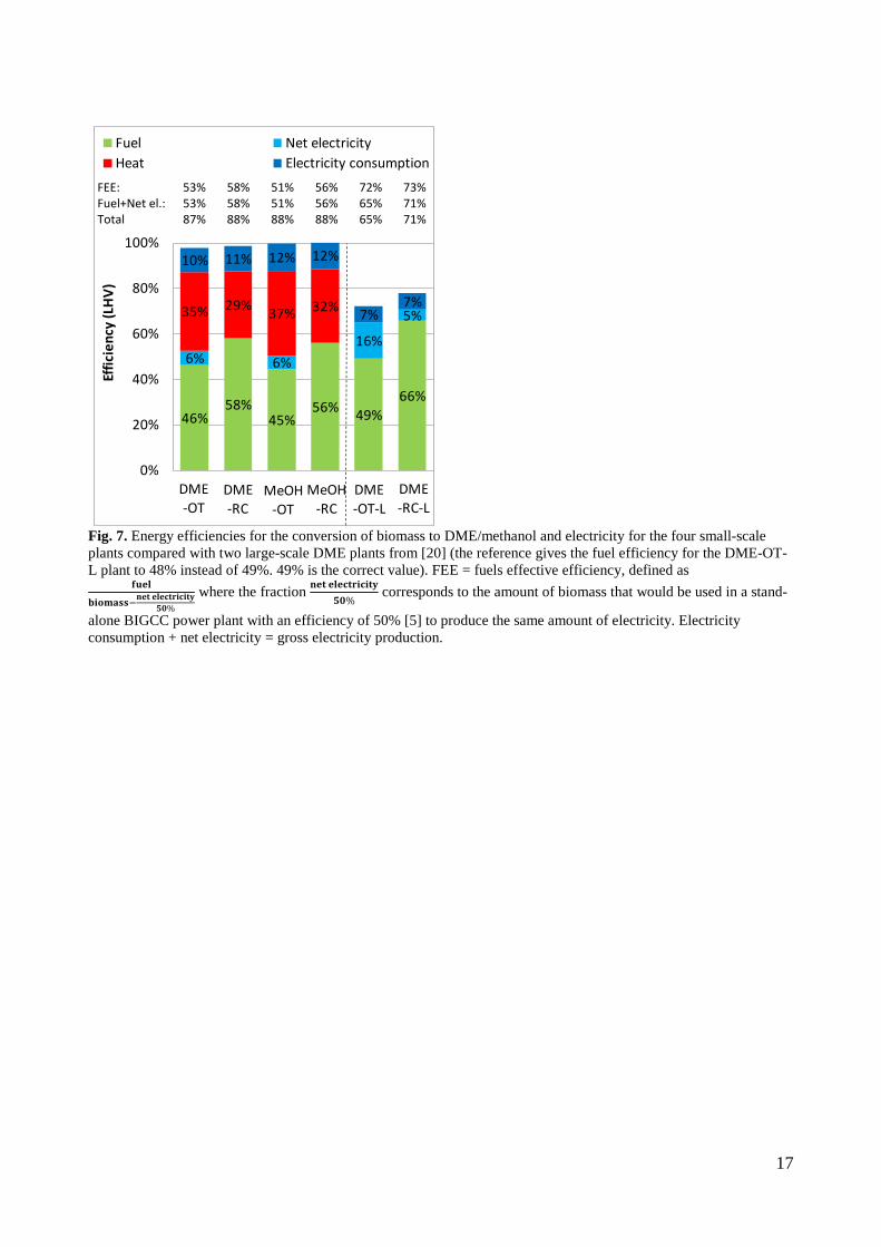
Fig. 7. Energy efficiencies for the conversion of biomass to DME/methanol and electricity for the four small-scale plants compared with two large-scale DME plants from [20] (the reference gives the fuel efficiency for the DME-OT-L plant to 48% instead of 49%. 49% is the correct value). FEE = fuels effective efficiency, defined as
𝐟𝐟𝐟𝐟𝐟𝐟𝐟𝐟
𝐛𝐛𝐛𝐛𝐛𝐛𝐛𝐛𝐛𝐛𝐛𝐛𝐛𝐛−𝐧𝐧𝐟𝐟𝐧𝐧 𝐟𝐟𝐟𝐟𝐟𝐟𝐞𝐞𝐧𝐧𝐞𝐞𝐛𝐛𝐞𝐞𝐛𝐛𝐧𝐧𝐞𝐞𝟓𝟓𝟓𝟓% where the fraction 𝐧𝐧𝐟𝐟𝐧𝐧 𝐟𝐟𝐟𝐟𝐟𝐟𝐞𝐞𝐧𝐧𝐞𝐞𝐛𝐛𝐞𝐞𝐛𝐛𝐧𝐧𝐞𝐞
𝟓𝟓𝟓𝟓% corresponds to the amount of biomass that would be used in a stand-
alone BIGCC power plant with an efficiency of 50% [5] to produce the same amount of electricity. Electricity consumption + net electricity = gross electricity production.
46%58%
45%56% 49%
66%
6% 6%16%
5%35% 29% 37% 32%
10% 11% 12% 12%
7%7%
0%
20%
40%
60%
80%
100%
Effic
ienc
y (L
HV)
Fuel Net electricityHeat Electricity consumption
MeOH-RC
DME-OT
DME-RC
MeOH-OT
DME-RC-L
DME-OT-L
FEE: 53% 58% 51% 56% 72% 73% Fuel+Net el.: 53% 58% 51% 56% 65% 71% Total 87% 88% 88% 88% 65% 71%
17

Fig. 8. Chemical energy streams (LHV, dry) in the small-scale DME plants compared with two large-scale DME plants from [20]. The figure includes conversion heat losses. The conversion heat losses (excluding the torrefaction heat loss) are in the large-scale DME plants used by a steam plant to produce electricity. In the small-scale DME plants, the conversion heat losses are used internally in the gasifier and for steam drying of biomass. The torrefaction process does not occur in the large-scale DME plants, but decentralized. WGS = water gas shift.
DME-OT
46%100% 93%
DMEWood
7%
GasificationSynthesis
38%Engine9%
DME-RC
58%100% 93%
DMEWood
7%
GasificationSynthesis
24%Engine11%
44%100% 90%
DMEWood
DME-OT (large-scale)
Torrefaction
10%
Gasification
73%
WGS
70%
17%
Synthesis
18% Gas turbine8%3%
59%100% 90%
DMEWood
Torrefaction
10%
Gasification
73%
WGS
71%
17%
Synthesis
1% Off-gas boiler
11%2%
DME-RC (large-scale)
18
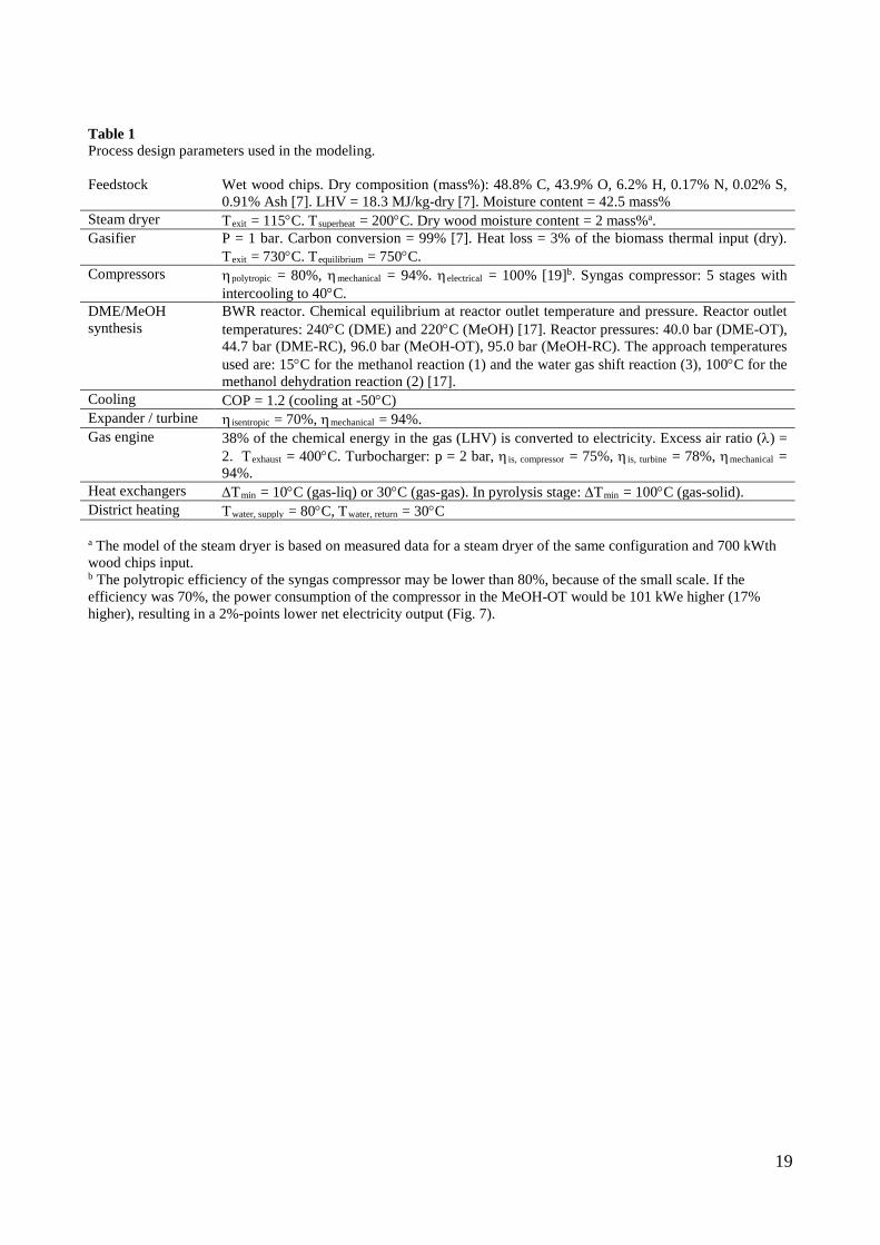
Table 1 Process design parameters used in the modeling. Feedstock Wet wood chips. Dry composition (mass%): 48.8% C, 43.9% O, 6.2% H, 0.17% N, 0.02% S,
0.91% Ash [7]. LHV = 18.3 MJ/kg-dry [7]. Moisture content = 42.5 mass% Steam dryer Texit = 115°C. Tsuperheat = 200°C. Dry wood moisture content = 2 mass%a. Gasifier P = 1 bar. Carbon conversion = 99% [7]. Heat loss = 3% of the biomass thermal input (dry).
Texit = 730°C. Tequilibrium = 750°C. Compressors ηpolytropic = 80%, ηmechanical = 94%. ηelectrical = 100% [19]b. Syngas compressor: 5 stages with
intercooling to 40°C. DME/MeOH synthesis
BWR reactor. Chemical equilibrium at reactor outlet temperature and pressure. Reactor outlet temperatures: 240°C (DME) and 220°C (MeOH) [17]. Reactor pressures: 40.0 bar (DME-OT), 44.7 bar (DME-RC), 96.0 bar (MeOH-OT), 95.0 bar (MeOH-RC). The approach temperatures used are: 15°C for the methanol reaction (1) and the water gas shift reaction (3), 100°C for the methanol dehydration reaction (2) [17].
Cooling COP = 1.2 (cooling at -50°C) Expander / turbine η isentropic = 70%, ηmechanical = 94%. Gas engine 38% of the chemical energy in the gas (LHV) is converted to electricity. Excess air ratio (λ) =
2. Texhaust = 400°C. Turbocharger: p = 2 bar, η is, compressor = 75%, η is, turbine = 78%, ηmechanical = 94%.
Heat exchangers ∆Tmin = 10°C (gas-liq) or 30°C (gas-gas). In pyrolysis stage: ∆Tmin = 100°C (gas-solid). District heating Twater, supply = 80°C, Twater, return = 30°C a The model of the steam dryer is based on measured data for a steam dryer of the same configuration and 700 kWth wood chips input. b The polytropic efficiency of the syngas compressor may be lower than 80%, because of the small scale. If the efficiency was 70%, the power consumption of the compressor in the MeOH-OT would be 101 kWe higher (17% higher), resulting in a 2%-points lower net electricity output (Fig. 7).
19

Table 2 Stream compositions for the DME-OT plant (stream numbers refer to Fig. 3) Gasifier
exit Reactor
inlet Reactor
outleta To
expander To distil-
lation CO2 to engine
Gas to engineb
DMEc
Stream number 9 21 22 30 46d 48 33 49d Mass flow (kg/s) 0.707 0.633 0.633 0.412 0.221 0.136 0.547 0.086 Flow (mole/s) 34.2 30.1 22.8 17.6 5.18 3.14 20.7 2.04 Mole frac (%) H2 30.0 34.1 20.2 26.1 0.20 0.33 22.2 0.00 CO 20.4 23.2 7.3 9.3 0.35 0.58 8.0 0.00 CO2 11.0 12.5 23.8 13.7 58.0 95.7 26.1 0.00 H2O 12.4 0.42 0.84 0.00 3.7 0.00 0.00 9.3 CH4 0.76 0.87 1.1 1.4 0.30 0.49 1.3 0.00 N2 25.1 28.5 37.7 48.4 1.7 2.7 41.4 0.00 Ar 0.30 0.34 0.45 0.56 0.06 0.09 0.49 0.00 CH3OH - - 0.92 0.00 4.1 0.00 0.00 10.3 CH3OCH3 - - 7.6 0.48 31.7 0.05 0.41 80.4 a The syngas conversion in the DME reactor is 64% (55% H2-conversion and 76% CO-conversion). b The energy content in the gas to the engine is 7.8 MJ/m3 (LHV). c The flow of methanol-equivalent is 3.49 mole/s (1 mole of DME is 2 mole methanol-equivalent). d Liquid.
20
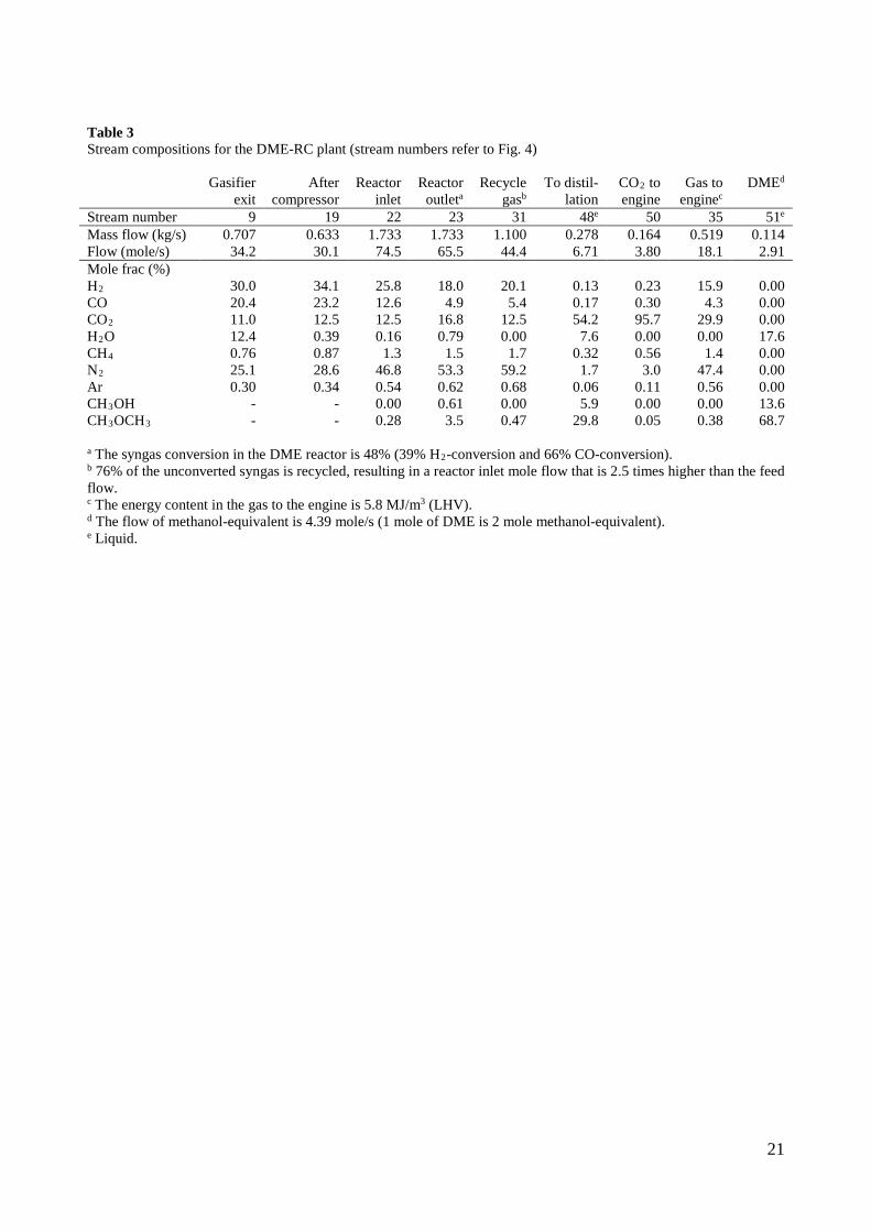
Table 3 Stream compositions for the DME-RC plant (stream numbers refer to Fig. 4) Gasifier
exit After
compressor Reactor
inlet Reactor
outleta Recycle
gasb To distil-
lation CO2 to engine
Gas to enginec
DMEd
Stream number 9 19 22 23 31 48e 50 35 51e Mass flow (kg/s) 0.707 0.633 1.733 1.733 1.100 0.278 0.164 0.519 0.114 Flow (mole/s) 34.2 30.1 74.5 65.5 44.4 6.71 3.80 18.1 2.91 Mole frac (%) H2 30.0 34.1 25.8 18.0 20.1 0.13 0.23 15.9 0.00 CO 20.4 23.2 12.6 4.9 5.4 0.17 0.30 4.3 0.00 CO2 11.0 12.5 12.5 16.8 12.5 54.2 95.7 29.9 0.00 H2O 12.4 0.39 0.16 0.79 0.00 7.6 0.00 0.00 17.6 CH4 0.76 0.87 1.3 1.5 1.7 0.32 0.56 1.4 0.00 N2 25.1 28.6 46.8 53.3 59.2 1.7 3.0 47.4 0.00 Ar 0.30 0.34 0.54 0.62 0.68 0.06 0.11 0.56 0.00 CH3OH - - 0.00 0.61 0.00 5.9 0.00 0.00 13.6 CH3OCH3 - - 0.28 3.5 0.47 29.8 0.05 0.38 68.7 a The syngas conversion in the DME reactor is 48% (39% H2-conversion and 66% CO-conversion). b 76% of the unconverted syngas is recycled, resulting in a reactor inlet mole flow that is 2.5 times higher than the feed flow. c The energy content in the gas to the engine is 5.8 MJ/m3 (LHV). d The flow of methanol-equivalent is 4.39 mole/s (1 mole of DME is 2 mole methanol-equivalent). e Liquid.
21

Table 4 Stream compositions for the MeOH-OT plant (stream numbers refer to Fig. 5) Gasifier
exit Reactor
inlet Reactor
outleta To
expander To distil-
lation CO2 to engine
Gas to engineb
MeOHc
Stream number 7 19 20 25 41d 42 28 43d Mass flow (kg/s) 0.784 0.648 0.648 0.509 0.139 0.026 0.535 0.113 Flow (mole/s) 38.7 31.1 23.7 19.5 4.19 0.63 20.2 3.57 Mole frac (%) H2 29.9 37.1 17.5 21.2 0.15 0.99 20.6 0.00 CO 14.9 18.6 8.8 10.6 0.13 0.85 10.3 0.00 CO2 12.8 15.9 20.9 22.7 12.7 85.4 24.6 0.00 H2O 19.7 0.24 0.32 0.01 1.8 0.00 0.01 2.1 CH4 0.71 0.88 1.2 1.4 0.08 0.53 1.4 0.00 N2 21.7 27.0 35.4 42.9 0.52 3.5 41.6 0.00 Ar 0.26 0.32 0.42 0.51 0.02 0.13 0.49 0.00 CH3OH - - 15.6 0.77 84.6 8.6 1.0 97.9 a The syngas conversion in the methanol reactor is 64% (64% H2-conversion and 64% CO-conversion). b The energy content in the gas to the engine is 7.8 MJ/m3 (LHV). c The flow of methanol is 3.49 mole/s. d Liquid.
22
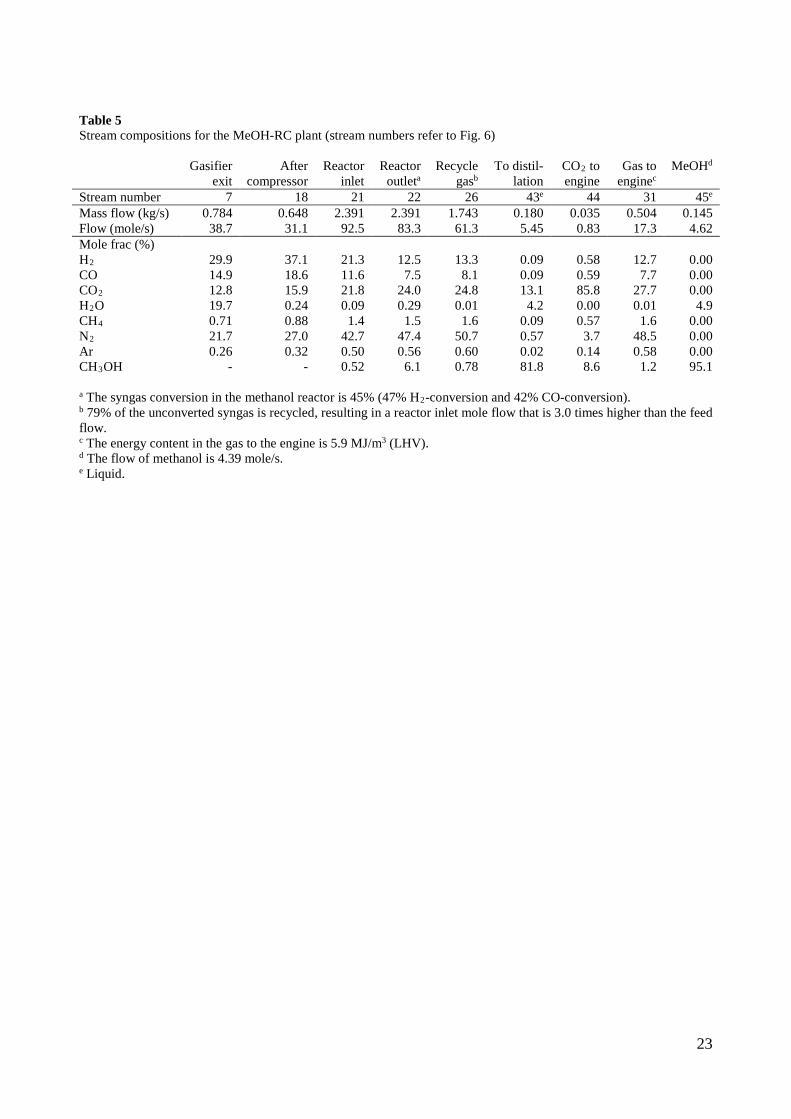
Table 5 Stream compositions for the MeOH-RC plant (stream numbers refer to Fig. 6) Gasifier
exit After
compressor Reactor
inlet Reactor
outleta Recycle
gasb To distil-
lation CO2 to engine
Gas to enginec
MeOHd
Stream number 7 18 21 22 26 43e 44 31 45e Mass flow (kg/s) 0.784 0.648 2.391 2.391 1.743 0.180 0.035 0.504 0.145 Flow (mole/s) 38.7 31.1 92.5 83.3 61.3 5.45 0.83 17.3 4.62 Mole frac (%) H2 29.9 37.1 21.3 12.5 13.3 0.09 0.58 12.7 0.00 CO 14.9 18.6 11.6 7.5 8.1 0.09 0.59 7.7 0.00 CO2 12.8 15.9 21.8 24.0 24.8 13.1 85.8 27.7 0.00 H2O 19.7 0.24 0.09 0.29 0.01 4.2 0.00 0.01 4.9 CH4 0.71 0.88 1.4 1.5 1.6 0.09 0.57 1.6 0.00 N2 21.7 27.0 42.7 47.4 50.7 0.57 3.7 48.5 0.00 Ar 0.26 0.32 0.50 0.56 0.60 0.02 0.14 0.58 0.00 CH3OH - - 0.52 6.1 0.78 81.8 8.6 1.2 95.1 a The syngas conversion in the methanol reactor is 45% (47% H2-conversion and 42% CO-conversion). b 79% of the unconverted syngas is recycled, resulting in a reactor inlet mole flow that is 3.0 times higher than the feed flow. c The energy content in the gas to the engine is 5.9 MJ/m3 (LHV). d The flow of methanol is 4.39 mole/s. e Liquid.
23