Embed Size (px)
Citation preview
NO. E2HA-917ISSUED: OCT.10,2013REVISED:
SERVICE MANUAL
HOSHIZAKICUBE ICE DISPENSER
MODEL DIM-30DE-1
i
CONTENTS PAGE
I. SPECIFICATIONS -------------------------------------------------------------------------------------11. DIMENSIONS/CONNECTIONS ----------------------------------------------------------------1
II. GENERAL INFORMATION -------------------------------------------------------------------------21. CONSTRUCTION ----------------------------------------------------------------------------------2
[a] OVERVIEW --------------------------------------------------------------------------------------2[b] WATER CIRCUIT AND MACHINE COMPARTMENT ---------------------------------3
2. CONTROLLER BOARD --------------------------------------------------------------------------4[a] CONTROLLER BOARD LAYOUT ---------------------------------------------------------5[b] BEFORE CHECKING CONTROLLER BOARD ----------------------------------------6[c] SEQUENCE - LED INDICATORS ON/OFF PATTERN -------------------------------7[d] FAULT DIAGNOSIS ---------------------------------------------------------------------------8[e] CONTROLS AND ADJUSTMENT ------------------------------------------------------- 10
III. OPERATING INSTRUCTIONS ------------------------------------------------------------------ 121. IN CASE OF LOW WATER -------------------------------------------------------------------- 122. PREPARING THE ICE DISPENSER FOR LONG STORAGE ------------------------ 12
IV. MAINTENANCE ------------------------------------------------------------------------------------ 131. SPOUT, ICE STATION, PUSH BUTTON --------------------------------------------------- 132. AIR FILTER ----------------------------------------------------------------------------------------- 133. DRAIN PAN, STORAGE BIN, FRONT PANEL (UPPER) ------------------------------- 144. ICE STATION DRAIN TRAP ------------------------------------------------------------------- 145. WATER VALVE ------------------------------------------------------------------------------------ 15
V. TECHNICAL INFORMATION --------------------------------------------------------------------- 161. WATER CIRCUIT AND REFRIGERANT CIRCUIT --------------------------------------- 162. WIRING DIAGRAM ------------------------------------------------------------------------------ 173. TIMING CHART ----------------------------------------------------------------------------------- 18
[a] NORMAL OPERATION --------------------------------------------------------------------- 18[b] BIN CONTROL -------------------------------------------------------------------------------- 19
4. SEQUENCE --------------------------------------------------------------------------------------- 205. PERFORMANCE DATA ------------------------------------------------------------------------- 22
VI. SERVICE DIAGNOSIS --------------------------------------------------------------------------- 231. NO ICE PRODUCTION ------------------------------------------------------------------------- 232. LOW ICE PRODUCTION ----------------------------------------------------------------------- 253. ABNORMAL ICE ---------------------------------------------------------------------------------- 254. OTHERS -------------------------------------------------------------------------------------------- 26
VII. REMOVAL AND REPLACEMENT------------------------------------------------------------- 271. PANELS --------------------------------------------------------------------------------------------- 27
[a] FRONT PANEL (UPPER) ------------------------------------------------------------------ 27[b] FRONT PANEL (LOWER) ----------------------------------------------------------------- 27[c] TOP PANEL ------------------------------------------------------------------------------------ 27
ii
[d] AIR GUIDE ------------------------------------------------------------------------------------- 27[e] REFRIGERATOR COVERS --------------------------------------------------------------- 28[f] SWITCH BOX ---------------------------------------------------------------------------------- 28
2. SERVICE FOR REFRIGERANT LINES ---------------------------------------------------- 29[a] SERVICE INFORMATION ----------------------------------------------------------------- 29[b] REFRIGERANT RECOVERY ------------------------------------------------------------- 30[c] EVACUATING AND RECHARGE -------------------------------------------------------- 30
3. COMPRESSOR ----------------------------------------------------------------------------------- 314. DRIER ----------------------------------------------------------------------------------------------- 325. EVAPORATOR ------------------------------------------------------------------------------------ 336. HOT GAS VALVE --------------------------------------------------------------------------------- 347. WATER PAN ASSEMBLY ---------------------------------------------------------------------- 358. PUMP MOTOR ------------------------------------------------------------------------------------ 369. WATER VALVE ------------------------------------------------------------------------------------ 36
10. ACTUATOR MOTOR ---------------------------------------------------------------------------- 3711. CAM ARM ------------------------------------------------------------------------------------------ 37
[a] CAM ARM (A) - ACTUATOR MOTOR SIDE ------------------------------------------- 37[b] CAM ARM (B) - REAR SIDE -------------------------------------------------------------- 37
12. ACTUATOR TOGGLE SWITCH -------------------------------------------------------------- 3813. CONTROLLER BOARD ------------------------------------------------------------------------ 40
[a] MODIFICATION ------------------------------------------------------------------------------ 40[b] REPLACEMENT ----------------------------------------------------------------------------- 41
14. THERMISTOR FOR CUBE CONTROL ----------------------------------------------------- 4215. FAN MOTOR -------------------------------------------------------------------------------------- 4316. GEAR MOTOR ------------------------------------------------------------------------------------ 4317. BIN CONTROL SWITCH ----------------------------------------------------------------------- 4418. TRANSFORMER --------------------------------------------------------------------------------- 4519. POWER SUPPLY CORD ----------------------------------------------------------------------- 4520. PUSH BUTTON SWITCH AND PILOT LAMP --------------------------------------------- 46
1
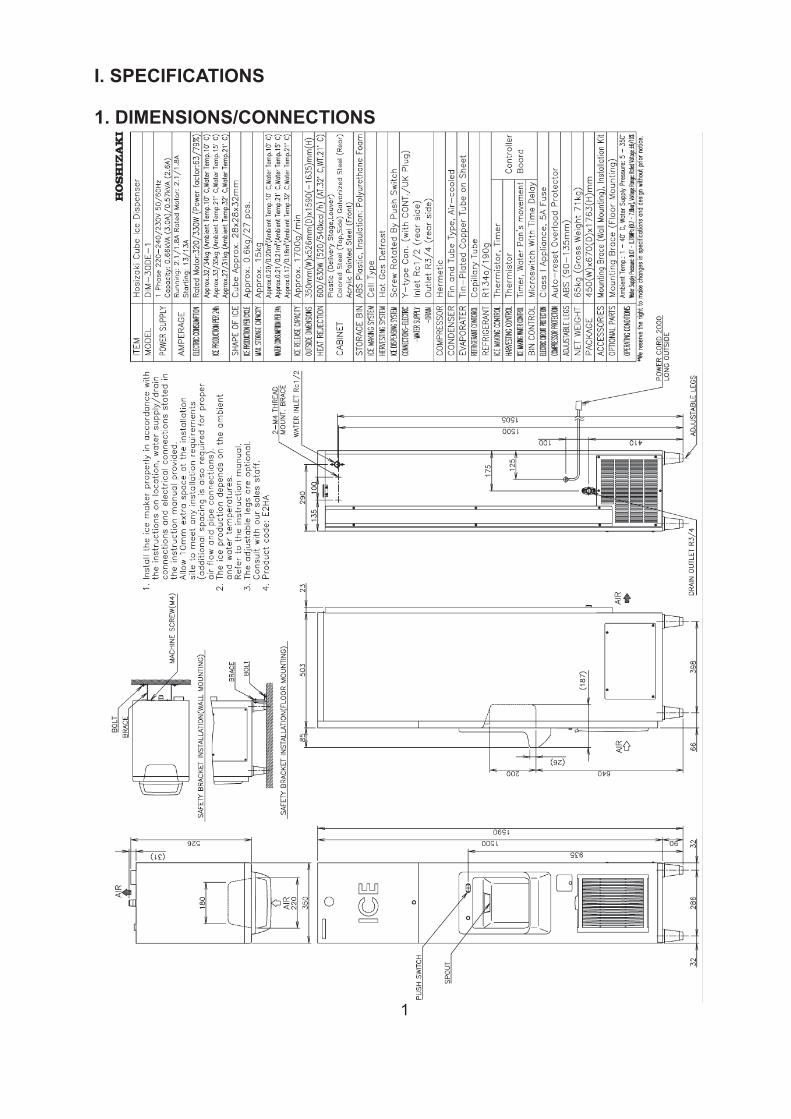
I. SPECIFICATIONS
1. DIMENSIONS/CONNECTIONS
2
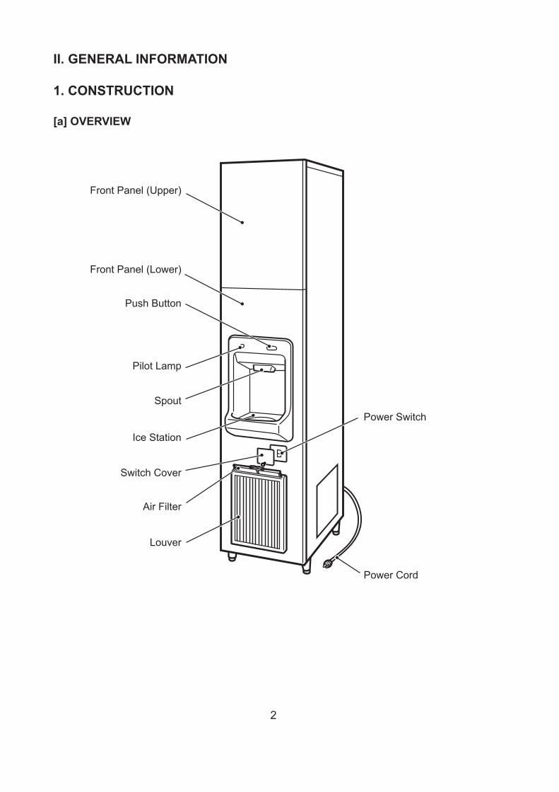
II. GENERAL INFORMATION
1. CONSTRUCTION
[a] OVERVIEW
Power Switch
Power Cord
Front Panel (Upper)
Front Panel (Lower)
Push Button
Pilot Lamp
Spout
Ice Station
Switch Cover
Air Filter
Louver
3
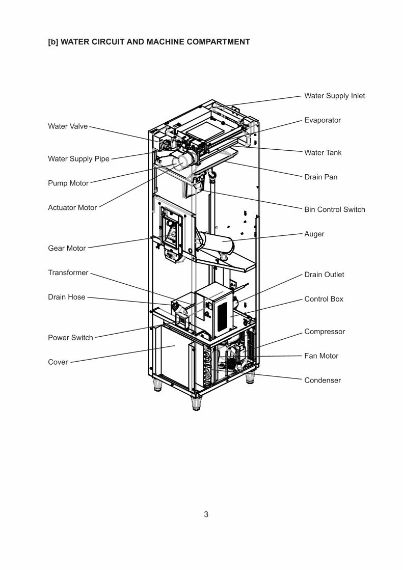
[b] WATER CIRCUIT AND MACHINE COMPARTMENT
Water Valve
Water Supply Pipe
Pump Motor
Actuator Motor
Gear Motor
Transformer
Drain Hose
Power Switch
Cover
Water Supply Inlet
Evaporator
Water Tank
Drain Pan
Bin Control Switch
Auger
Drain Outlet
Control Box
Compressor
Fan Motor
Condenser
4
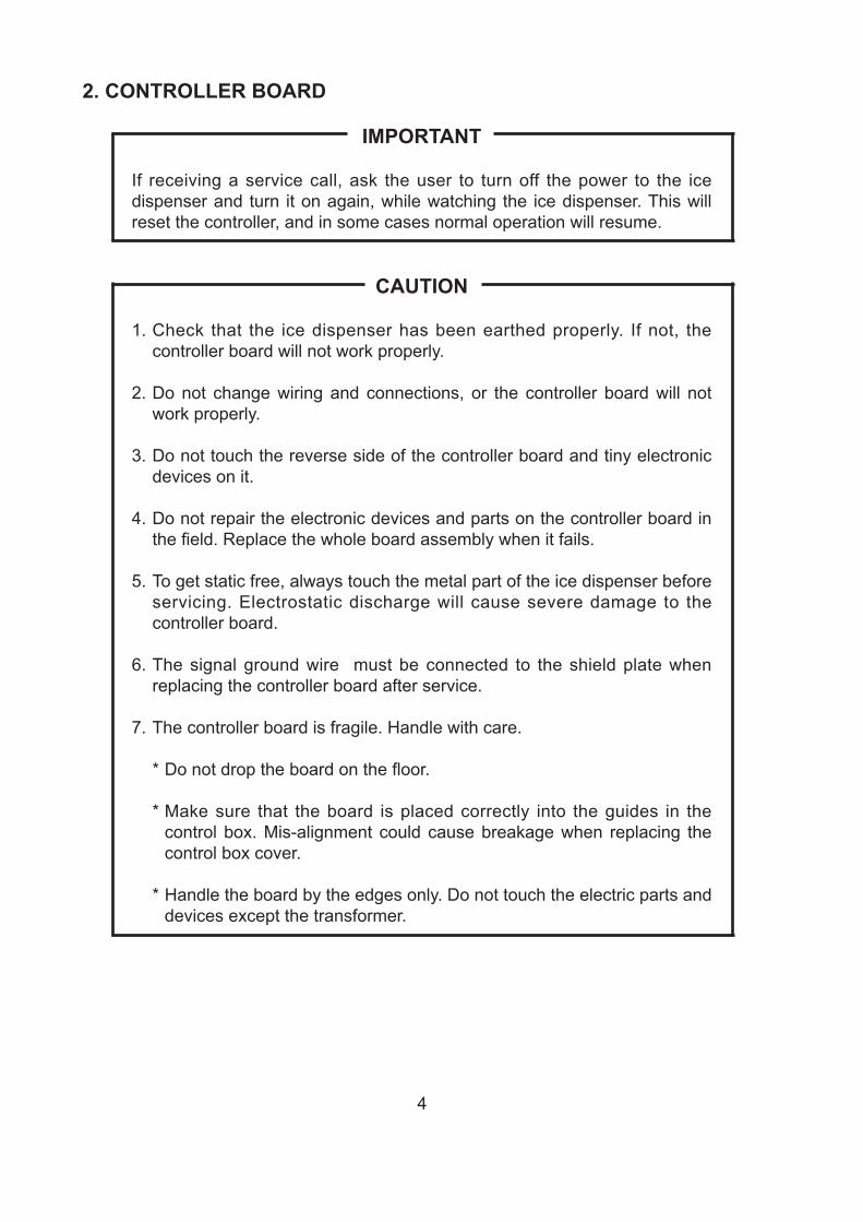
2. CONTROLLER BOARD
IMPORTANT
If receiving a service call, ask the user to turn off the power to the ice dispenser and turn it on again, while watching the ice dispenser. This will reset the controller, and in some cases normal operation will resume.
CAUTION
1. Check that the ice dispenser has been earthed properly. If not, the controller board will not work properly.
2. Do not change wiring and connections, or the controller board will not work properly.
3. Do not touch the reverse side of the controller board and tiny electronic devices on it.
4. Do not repair the electronic devices and parts on the controller board in the field. Replace the whole board assembly when it fails.
5. To get static free, always touch the metal part of the ice dispenser before servicing. Electrostatic discharge will cause severe damage to the controller board.
6. The signal ground wire must be connected to the shield plate when replacing the controller board after service.
7. The controller board is fragile. Handle with care.
* Do not drop the board on the floor.
* Make sure that the board is placed correctly into the guides in the control box. Mis-alignment could cause breakage when replacing the control box cover.
* Handle the board by the edges only. Do not touch the electric parts and devices except the transformer.
5
2
2. INPUT/OUTPUT
[a] INPUT/OUTPUT LAYOUT
The layout of the main inputs and outputs (connectors etc.) of the Controller Board is as shown below.
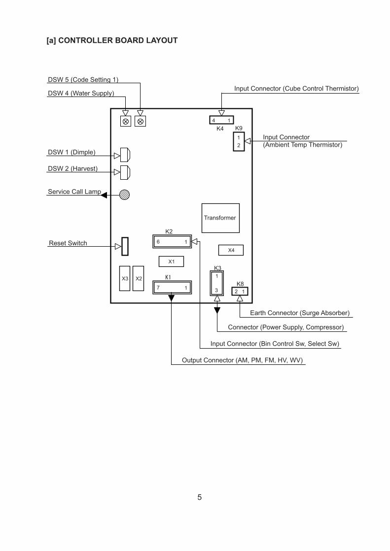
Input Connector (Ambient Temp Thermistor)
Earth Connector (Surge Absorber)
X1K31
3
K1
17
K44 1
K912
K82 1
Transformer
X2
X4
X3
K2
16
Input Connector (Cube Control Thermistor)
Connector (Power Supply, Compressor)
Input Connector (Bin Control Sw, Select Sw)
Output Connector (AM, PM, FM, HV, WV)
Service Call Lamp
DSW 1 (Dimple)
Reset Switch
DSW 2 (Harvest)
DSW 4 (Water Supply)
DSW 5 (Code Setting 1)
[a] CONTROLLER BOARD LAYOUT
6
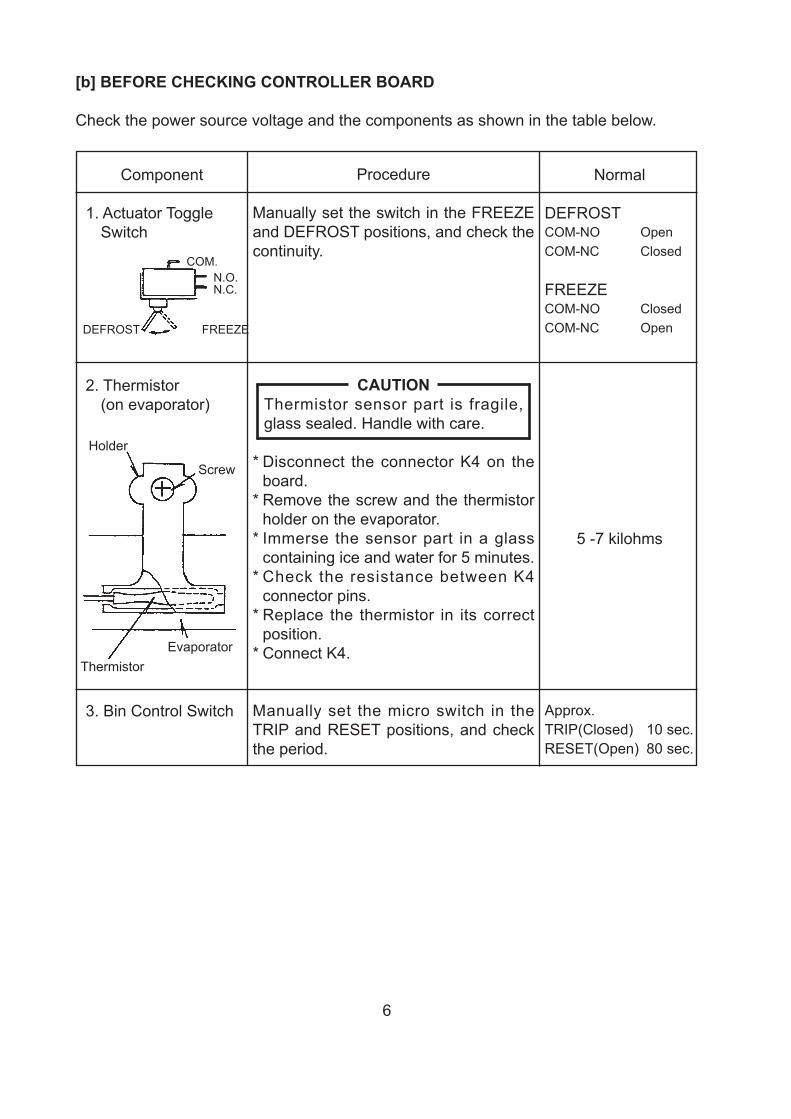
[b] BEFORE CHECKING CONTROLLER BOARD
Check the power source voltage and the components as shown in the table below.
Component
1. Actuator Toggle Switch
2. Thermistor(on evaporator)
3. Bin Control Switch
COM.N.O.N.C.
DEFROST FREEZE
Holder
Screw
ThermistorEvaporator
Procedure
Manually set the switch in the FREEZE and DEFROST positions, and check the continuity.
CAUTIONThermistor sensor part is fragile, glass sealed. Handle with care.
* Disconnect the connector K4 on the board.
* Remove the screw and the thermistor holder on the evaporator.
* Immerse the sensor part in a glass containing ice and water for 5 minutes.
* Check the resistance between K4 connector pins.
* Replace the thermistor in its correct position.
* Connect K4.
Manually set the micro switch in the TRIP and RESET positions, and check the period.
Normal
DEFROSTCOM-NO OpenCOM-NC Closed
FREEZECOM-NO ClosedCOM-NC Open
5 -7 kilohms
Approx.TRIP(Closed) 10 sec.RESET(Open) 80 sec.
712
[d] SEQUENCE
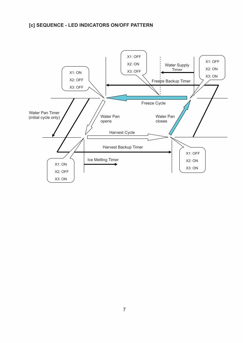
X1: OFF
X2: ON
X3: OFF
Freeze Cycle
Water Pancloses
Harvest Cycle
Freeze Backup Timer
Water Supply Timer
Harvest Backup Timer
Ice Melting Timer
Water Pan Timer (initial cycle only) Water Pan
opens
X1: OFF
X2: ON
X3: ON
X1: OFF
X2: ON
X3: ON
X1: ON
X2: OFF
X3: ON
X1: ON
X2: OFF
X3: OFF
[c] SEQUENCE - LED INDICATORS ON/OFF PATTERN
8
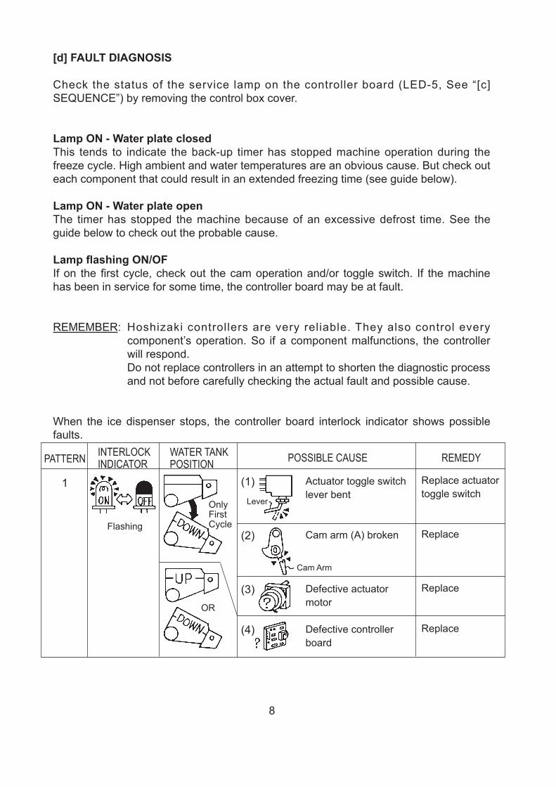
[d] FAULT DIAGNOSIS
Check the status of the service lamp on the controller board (LED-5, See “[c] SEQUENCE”) by removing the control box cover.
Lamp ON - Water plate closedThis tends to indicate the back-up timer has stopped machine operation during the freeze cycle. High ambient and water temperatures are an obvious cause. But check out each component that could result in an extended freezing time (see guide below).
Lamp ON - Water plate openThe timer has stopped the machine because of an excessive defrost time. See the guide below to check out the probable cause.
Lamp flashing ON/OFIf on the first cycle, check out the cam operation and/or toggle switch. If the machine has been in service for some time, the controller board may be at fault.
REMEMBER: Hoshizaki controllers are very reliable. They also control every component’s operation. So if a component malfunctions, the controller will respond.
Do not replace controllers in an attempt to shorten the diagnostic process and not before carefully checking the actual fault and possible cause.
When the ice dispenser stops, the controller board interlock indicator shows possible faults.
PATTERN
1 Actuator toggle switch lever bent
Cam arm (A) broken
Defective actuator motor
Defective controller board
Replace actuator toggle switch
Replace
Replace
Replace
(1)
(2)
(3)
(4)
Only First Cycle
OR
Flashing
Cam Arm
Lever
INTERLOCKINDICATOR
WATER TANKPOSITION POSSIBLE CAUSE REMEDY

9
PATTERN
2
3
4
Clogged air filter and/or condenser
Water leak from water solenoid valve
Gas leak from hot gas solenoid valve
Fan motor stopped
Gas leak
Compressor stopped
Hot gas solenoid valve closed and will not open
Gas leak
Compressor stopped
Actuator toggle switch lever bent
Cam arm (A) broken
Defective actuator motor
Cam pin damaged
Defective cube control thermistor
Clean or replace
Replace
Replace
Replace
Check for leak
Replace comp. starting capacitor
Replace
Check for leak
Replace comp. starting capacitor
Replace actuator toggle switch
Replace
Replace
Replace cam pin and cam arm (A)
Replace
(1)
(2)
(3)
(4)
(5)
(6)
(1)
(2)
(3)
(1)
(2)
(3)
(4)
(5)
Freeze Cycle
Defrost Cycle
Gas Leak0VHot
Leak
0V
Gas
100V
Gas
OR
Cam Arm
Lever
PinActuator Motor
INTERLOCKINDICATOR
WATER TANKPOSITION POSSIBLE CAUSE REMEDY
10
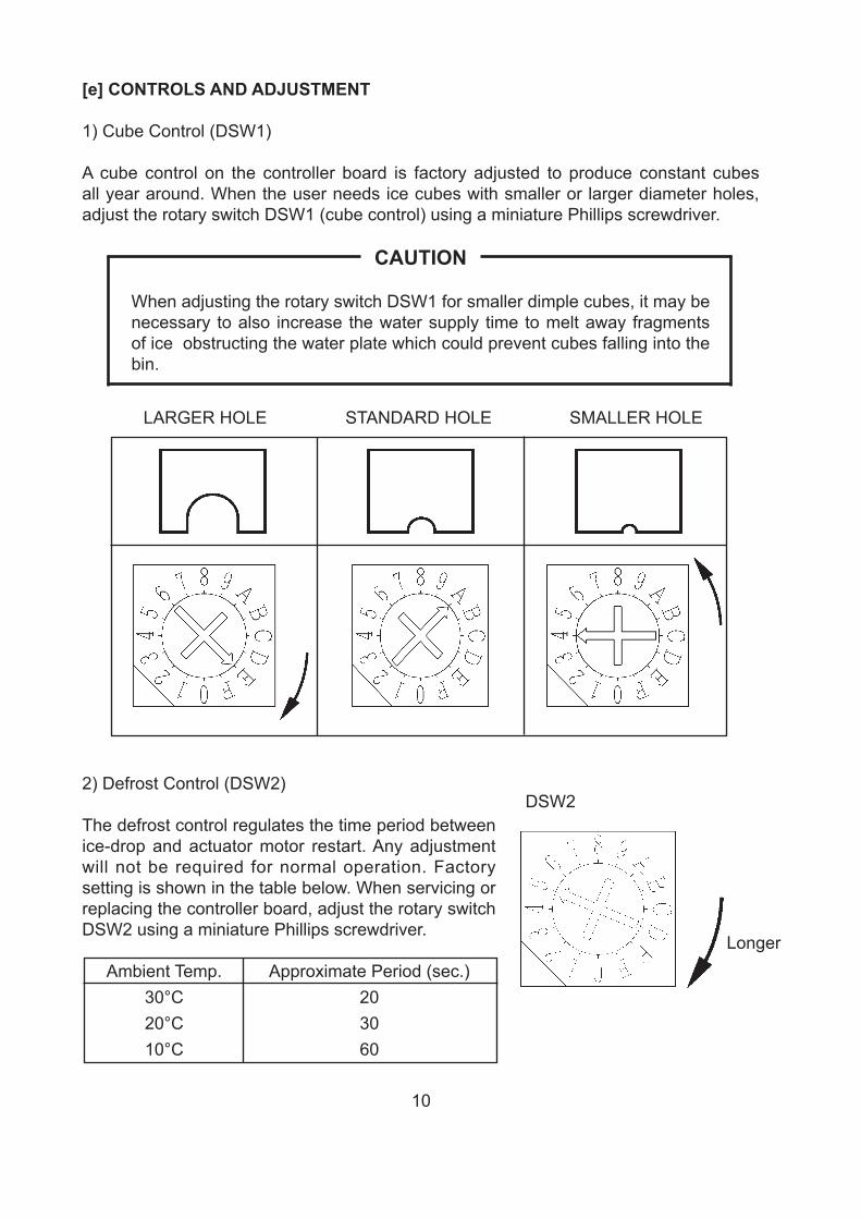
[e] CONTROLS AND ADJUSTMENT
1) Cube Control (DSW1)
A cube control on the controller board is factory adjusted to produce constant cubes all year around. When the user needs ice cubes with smaller or larger diameter holes, adjust the rotary switch DSW1 (cube control) using a miniature Phillips screwdriver.
CAUTION
When adjusting the rotary switch DSW1 for smaller dimple cubes, it may be necessary to also increase the water supply time to melt away fragments of ice obstructing the water plate which could prevent cubes falling into the bin.
LARGER HOLE STANDARD HOLE SMALLER HOLE
2) Defrost Control (DSW2)
The defrost control regulates the time period between ice-drop and actuator motor restart. Any adjustment will not be required for normal operation. Factory setting is shown in the table below. When servicing or replacing the controller board, adjust the rotary switch DSW2 using a miniature Phillips screwdriver.
Ambient Temp. Approximate Period (sec.) 30°C 20 20°C 30 10°C 60
Longer
DSW2
11
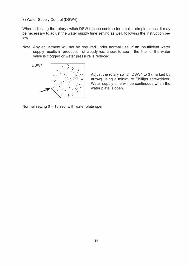
3) Water Supply Control (DSW4)
When adjusting the rotary switch DSW1 (cube control) for smaller dimple cubes, it may be necessary to adjust the water supply time setting as well, following the instruction be-low.
Note: Any adjustment will not be required under normal use. If an insufficient water supply results in production of cloudy ice, check to see if the filter of the water valve is clogged or water pressure is reduced.
Adjust the rotary switch DSW4 to 3 (marked by arrow) using a miniature Phillips screwdriver. Water supply time will be continuous when the water plate is open.
Normal setting 0 = 15 sec. with water plate open
DSW4
12
III. OPERATING INSTRUCTIONS
1. IN CASE OF LOW WATER
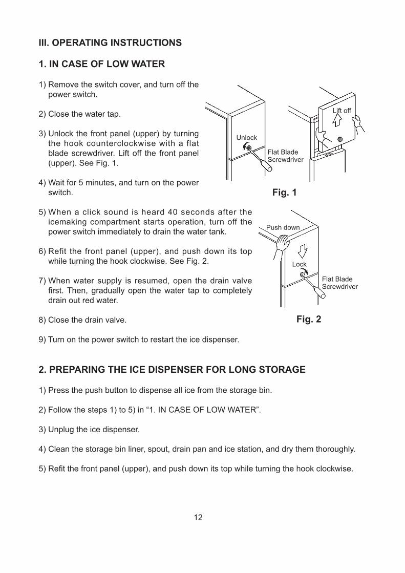
1) Remove the switch cover, and turn off the power switch.
2) Close the water tap.
3) Unlock the front panel (upper) by turning the hook counterclockwise with a flat blade screwdriver. Lift off the front panel (upper). See Fig. 1.
4) Wait for 5 minutes, and turn on the power switch.
5) When a click sound is heard 40 seconds after the icemaking compartment starts operation, turn off the power switch immediately to drain the water tank.
6) Refit the front panel (upper), and push down its top while turning the hook clockwise. See Fig. 2.
7) When water supply is resumed, open the drain valve first. Then, gradually open the water tap to completely drain out red water.
8) Close the drain valve.
9) Turn on the power switch to restart the ice dispenser.
2. PREPARING THE ICE DISPENSER FOR LONG STORAGE
1) Press the push button to dispense all ice from the storage bin.
2) Follow the steps 1) to 5) in “1. IN CASE OF LOW WATER”.
3) Unplug the ice dispenser.
4) Clean the storage bin liner, spout, drain pan and ice station, and dry them thoroughly.
5) Refit the front panel (upper), and push down its top while turning the hook clockwise.
Flat Blade Screwdriver
Unlock
Lift off
Fig. 1
Flat Blade Screwdriver
Lock
Push down
Fig. 2
13
IV. MAINTENANCE
WARNING
1. Before carrying out any cleaning or maintenance operations, unplug the ice dispenser from the electrical supply network.
2. A trained service person should clean and sanitize the ice dispenser water system at least twice a year. The condenser should be checked and cleaned at least once a year.
3. This appliance must not be cleaned by use of a water jet.
1. SPOUT, ICE STATION, PUSH BUTTON
Wipe the exterior and ice station at least once per week with a clean, soft cloth. Use a damp cloth containing a neutral cleaner to wipe off grease or dirt.
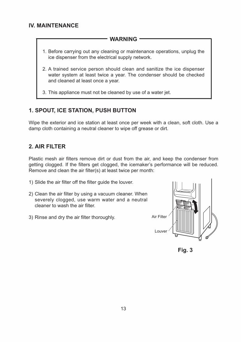
2. AIR FILTER
Plastic mesh air filters remove dirt or dust from the air, and keep the condenser from getting clogged. If the filters get clogged, the icemaker’s performance will be reduced. Remove and clean the air filter(s) at least twice per month:
1) Slide the air filter off the filter guide the louver.
2) Clean the air filter by using a vacuum cleaner. When severely clogged, use warm water and a neutral cleaner to wash the air filter.
3) Rinse and dry the air filter thoroughly.
Fig. 3
Louver
Air Filter
14
Fig. 4
Drain Pan
Bin Control Switch LeadRecess
Fig. 5
Cap
Ice Station
Fig. 6
Tab
Notch
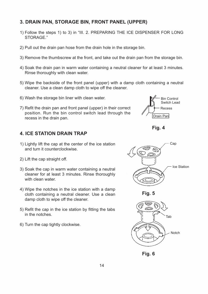
3. DRAIN PAN, STORAGE BIN, FRONT PANEL (UPPER)
1) Follow the steps 1) to 3) in “III. 2. PREPARING THE ICE DISPENSER FOR LONG STORAGE.”
2) Pull out the drain pan hose from the drain hole in the storage bin.
3) Remove the thumbscrew at the front, and take out the drain pan from the storage bin.
4) Soak the drain pan in warm water containing a neutral cleaner for at least 3 minutes. Rinse thoroughly with clean water.
5) Wipe the backside of the front panel (upper) with a damp cloth containing a neutral cleaner. Use a clean damp cloth to wipe off the cleaner.
6) Wash the storage bin liner with clean water.
7) Refit the drain pan and front panel (upper) in their correct position. Run the bin control switch lead through the recess in the drain pan.
4. ICE STATION DRAIN TRAP
1) Lightly lift the cap at the center of the ice station and turn it counterclockwise.
2) Lift the cap straight off.
3) Soak the cap in warm water containing a neutral cleaner for at least 3 minutes. Rinse thoroughly with clean water.
4) Wipe the notches in the ice station with a damp cloth containing a neutral cleaner. Use a clean damp cloth to wipe off the cleaner.
5) Refit the cap in the ice station by fitting the tabs in the notches.
6) Turn the cap tightly clockwise.

15
5. WATER VALVE
1) Unplug the ice dispenser or disconnect the power source.
2) Close the water supply tap.
3) Remove the top panel and front panel (upper).
4) Disconnect the fitting nut from the water valve.
5) Remove the mesh filter from the water valve.
6) Clean the mesh using a brush.
7) Replace the mesh and fitting nut in their correct positions.
8) Open the water supply tap.
9) Plug in the ice dispenser or connect the power source.
10) Check for leaks.
11) Replace the panels in their correct positions.
Fig. 7

16
V. TECHNICAL INFORMATION
1. WATER CIRCUIT AND REFRIGERANT CIRCUIT
Water Valve
Evaporator
Pump Motor
Water Tank
Capillary Tube
Hot Gas ValveDrier
Condenser
Fan Motor
Compressor
Water Circuit
Refrigerant Circuit
Strainer
U Trap
Drain Outlet
Ice Station
Trap
AccumulatorController BoardActuator
Motor
Drain Pan Storage Bin
Bin Control Switch

17
2. WIRING DIAGRAM
18
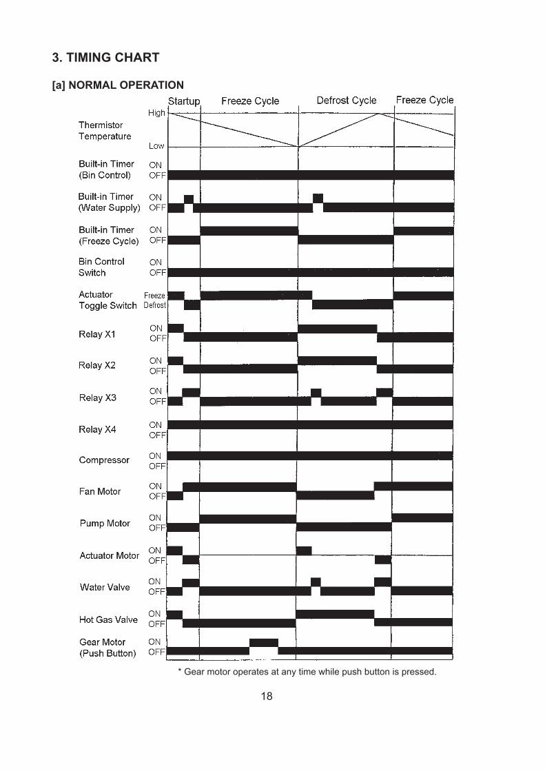
* Gear motor operates at any time while push button is pressed.
3. TIMING CHART
[a] NORMAL OPERATION

19
* Gear motor operates at any time while push button is pressed.
[b] BIN CONTROL

20
4. SEQUENCE
1) When the water supply tap is opened and the unit is energized, the hot gas valve opens to let hot gas flow and the actuator motor starts to open the water pan.
When the cam pushes down the actuator toggle switch lever to the left, the hot gas valve closes and the actuator motor starts to turn in the reverse direction. Meanwhile the water valve opens to supply ice making water and the water pan closes to start a freeze cycle.
The ice making water supplied to the water pan runs through the return hole into the water tank. The actuator toggle switch trips to close the water valve and stop the water supply. When the water in the water tank reaches a specific level (approx. 1.3L), it drains out into the drain pan.
2) The ice making water is pumped up by the pump motor from the bottom of the water tank into the water pan and jets out of the tiny holes in the branch pipes. Ice starts to form gradually from outside to inside in the refrigerated evaporator cells.
When ice has formed completely and the evaporator temperature goes down to a specific level, the thermistor detects the completion of the freeze cycle to stop the pump motor and start the actuator motor in the direction to open the water pan.
3) When the freeze cycle completes, the hot gas valve opens immediately to let hot gas flow and the actuator motor starts to open the water pan.
When the cam pushes down the actuator toggle switch lever to the left, the actuator motor stops. Meanwhile the water valve opens, and the supplied water washes the water pan top surface for approx. 15 seconds and drains out into the drain pan.
The ice formed in the evaporator cells is slightly melt by hot gas and drops by gravity onto the water pan surface, then slides down into the storage bin.
After all the ice cubes have dropped, the thermistor senses the evaporator temperature to start the actuator motor in the direction to close the water pan, while the water valve opens. When the cam goes back to the original position to trip the actuator toggle switch, the actuator motor stops and the pump motor starts for another freeze cycle. The water valve closes to stop the water supply.
Evaporator Pipe
Evaporator Cell
Water Pan AssemblyBranch Pipe
Ret
urn
Hol
eJe
t Hol
eR
etur
n H
ole
Freeze cycle starts Freeze cycle Defrost cycle
Fig. 8
21
4) As the unit repeats the above freeze and defrost cycles, the storage bin is gradually filled with ice. When a certain level is reached, the bin control switch (microswitch to shut off the circuit) detects the ice cubes to shut down the unit. When the storage level decreases, another freeze cycle starts.
The freeze cycle t ime depends on condit ions such as ambient and water temperatures. But the unit is capable of producing 27 pieces of 28 x 28 x 32 mm ice cubes (approx. 0.6 kg) in approx. 25 minutes.
5) When the push button switch is pressed, the gear motor starts the auger to dispense ice from the spout.

22
8
1214
12
10
8
6
4
9
8
7
6
5
8.8
7.1
320
290
1/5 10/10 21/15 32/21 38/32Ambient Temp./Water Temp. (°C)
350
300
250
Suc
tion
Pre
ssur
e (b
ar)
Wat
er C
onsu
mpt
ion
(L/h
)
Ele
ctric
Con
sum
ptio
n (W
)
Standard ice production capacity: 600 g/cycleStandard water valve flow rate: 3.8 L/min(Water pressure: 2 kg/cm2G)Average ice cube hole diameter: 5 ± 1 mm
32 3335
30
25
12
10
8
6
4
2
27
29.5
22.520.0
40
35
30
25
20
15
Ice
Pro
duct
ion
(kg/
d)D
efro
st C
ycle
(min
)
Free
ze C
ycle
Tim
e (m
in)
2.53.5
5. PERFORMANCE DATA
50Hz
1/5 10/10 21/15 32/21 38/32Ambient Temp./Water Temp. (°C)

23
VI. SERVICE DIAGNOSIS 1. NO ICE PRODUCTION
PROBLEM CHECK POSSIBLE CAUSE REMEDY 1. OFF position. 1. Move to ON position. 2. Loose connections. 2. Tighten.
a) Power source
3. Bad contacts. 3. Check for continuity and replace.
1. Loose connection. 1. Tighten. b) Power cord 2. Open circuit - damaged. 2. Repair or replace.
c) Fuse 1. Blown out. 1. Replace. 1. Tripped with bin filled with
ice. 1. Remove ice.
2. Out of position. 2. Place in position.
d) Bin control
3. Fused contacts. 3. Check for continuity and replace.
e) Transformer 1. Coil winding opened. 1. Replace. f) Wiring to
controller board 1. Loose connections or
open. 1. Check for continuity and
repair or replace. g) Thermistor 1. Leads short-circuit or
open and high temperature safety (backup timer) operates.
1. See “II. 2. [b] BEFORE CHECKING CONTROLLER BOARD”.
h) Hot gas solenoid valve
1. Continues to open in freeze cycle and high temperature safety (backup timer) operates.
1. Check for power OFF in freeze cycle and replace.
1. Mesh filter or orifice gets clogged and water supply cycle does not finish.
1. Clean.
2. Coil winding opened. 2. Replace.
i) Water solenoid valve
3. Wiring to water valve. 3. Check for loose connection or open, and replace.
[1] The ice dispenser will not start.
j) Controller board 1. Defective. 1. See “II. 2. CONTROLLER BOARD”.
1. Bad contacts. 1. Check for continuity and replace.
2. Voltage too low. 2. Check for recommended voltage.
a) Overload protector
3. Refrigerant overcharged or undercharged.
3. Recharge.
b) Starter 1. Defective. 1. Replace. c) Start capacitor or
run capacitor 1. Defective. 1. Replace.
1. Bad contacts. 1. Check for continuity and replace.
d) Power relay
2. Coil winding opened. 2. Replace. 1. Wiring to compressor. 1. Check for loose
connection or open, and repair or replace.
[2] Compressor will not start, or operates intermittently.
e) Compressor
2. Defective. 2. Replace.
24
PROBLEM CHECK POSSIBLE CAUSE REMEDY [2] (Continued) f) Air filter,
condenser 1. Clogged. 1. Clean.
[3] Compressor runs, but other components will not start.
a) Control circuit 1. Loose connection or broken wire.
1. Repair or replace.
a) Wiring 1. Loose connection or broken wire.
1. Repair or replace.
b) Actuator toggle switch
1. Defective. 1. Replace.
[4] Fan motor will not run.
c) Thermistor, controller board
1. See “II. 2. CONTROLLER BOARD”.
a) Water solenoid valve
1. Diaphragm does not close.
1. Check for water leaks with ice dispenser OFF.
[5] Water continues to be supplied in freeze cycle.
b) Controller board 1. Defective. 1. See “II. 2. CONTROLLER BOARD”.
a) Water supply line 1. Water pressure too low and water level in water tank too low.
1. Check for recommended pressure.
b) Water solenoid valve
1. Dirty mesh filter or orifice and water level in water tank too low.
1. Clean.
1. Water leaks. 1. Check connections for water leaks, and repair.
c) Water system
2. Clogged. 2. Clean. 1. Motor winding opened. 1. Replace. 2. Bearing worn out. 2. Replace. 3. Wiring to pump motor. 3. Check for loose
connection or open, and replace.
d) Pump motor
4. Defective or bound impeller.
4. Replace and clean.
e) Controller board 1. Defective. 1. See “II. 2. CONTROLLER BOARD”.
f) Actuator toggle switch
1. Defective. 1. Replace.
1. Clogged. 1. Clean.
[6] Water does not circulate.
g) Discharge tube 2. Out of position. 2. Place in position. 1. Undercharged. 1. Check for leaks and
recharge. a) Refrigerant
2. Air or moisture trapped. 2. Replace drier, and recharge.
b) Compressor 1. Defective valve. 1. Replace compressor.
[7] All components run, but no ice is produced.
c) Hot gas solenoid valve
1. Continues to open in freeze cycle.
1. Check and replace.
a) Wiring 1. Loose connection or broken wire.
1. Repair or replace.
b) Actuator toggle switch
1. Defective. 1. Replace.
c) Actuator motor, run capacitor
1. Defective. 1. Replace.
[8] Water pan will not open.
d) Thermistor, controller board
1. See “II. 2. CONTROLLER BOARD”.
25
PROBLEM CHECK POSSIBLE CAUSE REMEDY a) See [8] above. [9] Water pan will
not close. b) Hot gas valve 1. Defective. 1. Replace.
2. LOW ICE PRODUCTION
PROBLEM CHECK POSSIBLE CAUSE REMEDY a) Water supply 1. Low pressure. 1. Check for recommended
pressure. b) Water
temperature 1. Too high. 1. Check for recommended
water temperature. 1. High hardness or contains
impurities. 1. Install a water filter or
scale treatment. c) Water quality
2. Lime is deposited inside cooling water tubing.
2. Clean.
d) Refrigerant charge
1. Overcharged or undercharged.
1. Recharge correctly and check for leaks.
e) Refrigerant circuit 1. Excessive moisture. 1. Replace drier and recharge correctly.
f) Thermistor, controller board
1. See “II. 2. CONTROLLER BOARD”.
[1] Freeze cycle time is too long.
g) Air filter, condenser
1. Clogged. 1. Clean.
a) Evaporator 1. Scaled up. 1. Clean or remove scale. b) Refrigerant
charge 1. Undercharged. 1. Check for leaks and
recharge correctly. c) Hot gas valve 1. Defective. 1. Replace. d) Thermistor,
controller board 1. See “II. 2. CONTROLLER BOARD”.
[2] Takes too long for water pan to close.
e) Fan motor 1. Runs during defrost cycle. 1. Check wiring and actuator toggle switch.
3. ABNORMAL ICE
PROBLEM CHECK POSSIBLE CAUSE REMEDY a) Water supply line 1. Low pressure. 1. Check for recommended
pressure. b) Ambient or water
temperature 1. Too high. 1. Check for recommended
temperatures. c) Air filter,
condenser 1. Clogged. 1. Clean.
d) Water valve 1. Clogged. 1. Clean. e) Pump motor 1. Leaks. 1. Repair or replace. f) Refrigerant
charge 1. Undercharged. 1. Check for leaks and
recharge correctly.
[1] Large-hole cubes.
g) Thermistor, controller board
1. See “II. 2. CONTROLLER BOARD”.
1. Low pressure. 1. Check for recommended pressure.
[2] Cloudy cubes. a) Water supply line
2. Clogged. 2. Check strainer and clean.
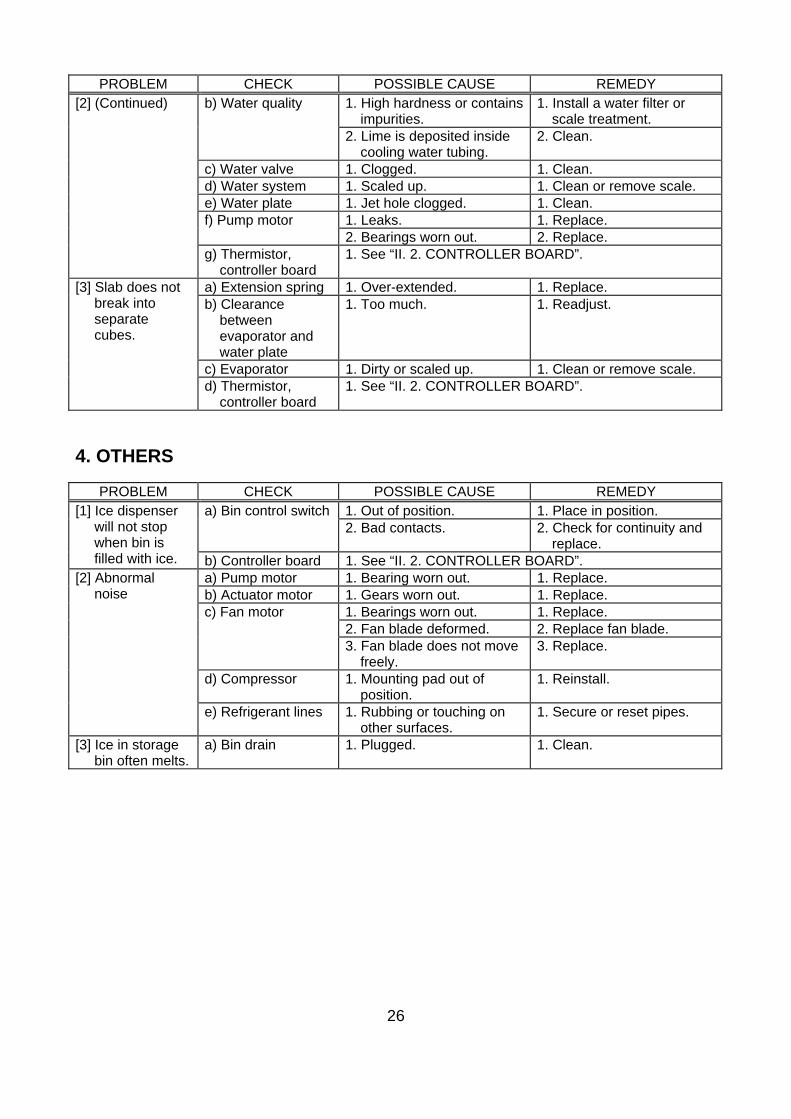
26
PROBLEM CHECK POSSIBLE CAUSE REMEDY 1. High hardness or contains
impurities. 1. Install a water filter or
scale treatment. b) Water quality
2. Lime is deposited inside cooling water tubing.
2. Clean.
c) Water valve 1. Clogged. 1. Clean. d) Water system 1. Scaled up. 1. Clean or remove scale. e) Water plate 1. Jet hole clogged. 1. Clean.
1. Leaks. 1. Replace. f) Pump motor 2. Bearings worn out. 2. Replace.
[2] (Continued)
g) Thermistor, controller board
1. See “II. 2. CONTROLLER BOARD”.
a) Extension spring 1. Over-extended. 1. Replace. b) Clearance
between evaporator and water plate
1. Too much. 1. Readjust.
c) Evaporator 1. Dirty or scaled up. 1. Clean or remove scale.
[3] Slab does not break into separate cubes.
d) Thermistor, controller board
1. See “II. 2. CONTROLLER BOARD”.
4. OTHERS
PROBLEM CHECK POSSIBLE CAUSE REMEDY 1. Out of position. 1. Place in position. a) Bin control switch2. Bad contacts. 2. Check for continuity and
replace.
[1] Ice dispenser will not stop when bin is filled with ice. b) Controller board 1. See “II. 2. CONTROLLER BOARD”.
a) Pump motor 1. Bearing worn out. 1. Replace. b) Actuator motor 1. Gears worn out. 1. Replace.
1. Bearings worn out. 1. Replace. 2. Fan blade deformed. 2. Replace fan blade.
c) Fan motor
3. Fan blade does not move freely.
3. Replace.
d) Compressor 1. Mounting pad out of position.
1. Reinstall.
[2] Abnormal noise
e) Refrigerant lines 1. Rubbing or touching on other surfaces.
1. Secure or reset pipes.
[3] Ice in storage bin often melts.
a) Bin drain 1. Plugged. 1. Clean.
27
VII. REMOVAL AND REPLACEMENT OF COMPONENTS
1. PANELS
[a] FRONT PANEL (UPPER)
1) Unlock the front panel (upper) by turning the hook counterclockwise with a flat blade screwdriver. Lift off the front panel (upper). See Fig. 1.
2) To refit the front panel (upper), push down the top while turning the hook clockwise. See Fig. 2.
[b] FRONT PANEL (LOWER)
1) Remove the louver, and turn off the power switch.
2) Remove the front panel (upper).
3) Remove the two screws securing the top of the front panel (lower).
4) Tilt the top of the front panel (lower) slightly toward you, and lift it off.
5) Disconnect the drain hose from the ice station.
6) Remove the connectors from the front panel (lower).
7) To refit the front panel (lower), reconnect the connectors and drain hose, put the bottom into the unit base, and secure the top with the screws.
[c] TOP PANEL
1) Remove the front panel (upper).
2) Unhook the rear of the top panel, and lift it off.
3) To refit the top panel, check that the insulation panel is securely in place before hooking the backside square hole of the top panel on the rear of the cabinet.
[d] AIR GUIDE
The air guide fitted with a vibration damper on backside is located at the front of the condenser to prevent noise from the machine compartment.
28
1) Remove the four machine screws securing the air guide to the cabinet.
2) To refit the air guide, reverse the above procedure.
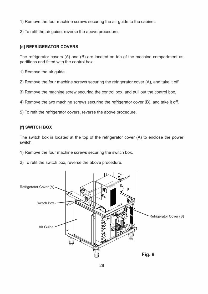
[e] REFRIGERATOR COVERS
The refrigerator covers (A) and (B) are located on top of the machine compartment as partitions and fitted with the control box.
1) Remove the air guide.
2) Remove the four machine screws securing the refrigerator cover (A), and take it off.
3) Remove the machine screw securing the control box, and pull out the control box.
4) Remove the two machine screws securing the refrigerator cover (B), and take it off.
5) To refit the refrigerator covers, reverse the above procedure.
[f] SWITCH BOX
The switch box is located at the top of the refrigerator cover (A) to enclose the power switch.
1) Remove the four machine screws securing the switch box.
2) To refit the switch box, reverse the above procedure.
Fig. 9
Refrigerator Cover (B)
Refrigerator Cover (A)
Switch Box
Air Guide
29
2. SERVICE FOR REFRIGERANT LINES
[a] SERVICE INFORMATION
1) Allowable Compressor Opening Time and Prevention of Lubricant Mixture [R134a]
The compressor must not be opened more than 30 minutes in replacement or service. Do not mix lubricants of different compressors even if both are charged with the same refrigerant, except when they use the same lubricant.
2) Treatment for Refrigerant Leak [R134a]
If a refrigerant leak occurs in the low side of an ice maker, air may be drawn in. Even if the low side pressure is higher than the atmospheric pressure in normal operation, a continuous refrigerant leak will eventually lower the low side pressure below the atmospheric pressure and will cause air suction. Air contains a large amount of moisture, and ester oil easily absorbs a lot of moisture. If an ice maker charged with R134a has possibly drawn in air, the drier must be replaced. Be sure to use a drier designed for R134a.
3) Handling of Handy Flux [R134a]
Repair of the refrigerant circuit needs brazing. It is no problem to use the same handy flux that has been used for the current refrigerants. However, its entrance into the refrigerant circuit should be avoided as much as possible.
4) Oil for Processing of Copper Tubing [R134a]
When processing the copper tubing for service, wipe off oil, if any used, by using alcohol or the like. Do not use too much oil or let it into the tubing, as wax contained in the oil will clog the capillary tubing.
5) Service Parts for R134a
Some parts used for refrigerants other than R134a are similar to those for R134a. But never use any parts unless they are specified for R134a because their endurance against the refrigerant has not been evaluated. Also, for R134a, do not use any parts that have been used for other refrigerants. Otherwise, wax and chlorine remaining on the parts may adversely affect R134a.
6) Replacement Copper Tubing [R134a]
The copper tubes currently in use are suitable for R134a. But do not use them if oily inside. The residual oil in copper tubes should be as little as possible. (Low residual oil type copper tubes are used in the shipped units.)

30
7) Evacuation, Vacuum Pump and Refrigerant Charge [R134a]
Never allow the oil in the vacuum pump to flow backward. The vacuum level and vacuum pump may be the same as those for the current refrigerants. However, the rubber hose and gauge manifold to be used for evacuation and refrigerant charge should be exclusively for R134a.
8) Refrigerant Leak Check
Refrigerant leaks can be detected by charging the unit with a little refrigerant, raising the pressure with nitrogen and using an electronic detector. Do not use air or oxygen instead of nitrogen for this purpose, or rise in pressure as well as in temperature may cause R134a to suddenly react with oxygen and explode. Be sure to use nitrogen to prevent explosion.
[b] REFRIGERANT RECOVERY
The refrigerant must be recovered if required by an applicable law. No refrigerant access valve is provided in the unit. Install a proper access valve on the low-side line (e.g. compressor process pipe). Recover the refrigerant from the access valve, and store it in a proper container. Do not discharge the refrigerant into the atmosphere.When replacing the drier, take the opportunity to also fit a high-side access valve for ease of charging liquid refrigerant.
[c] EVACUATION AND RECHARGE
1) Attach charging hoses, a service manifold and a vacuum pump to the system. If possible, use quick release connectors onto the access valves (especially on the high side).
2) Turn on the vacuum pump.
3) Allow the vacuum pump to pull down to a 760 mmHg vacuum. Evacuating period depends on the pump capacity.
4) Close the low-side and high-side valves on the service manifold.
5) Disconnect the vacuum pump, and attach a refrigerant charging cylinder to accurately weigh in the liquid charge. Remember to purge any air from the charging hose. See the nameplate for the required refrigerant charge.
6) Open the high-side valve on the gauge manifold, and accurately measure in the liquid charge. Close the valve on the charging cylinder before closing the high-side manifold valve. Any remaining liquid in the line can be charged into the low side.
31
Note: Always charge in the liquid stage, as many refrigerants are blends and vapour charging will affect the blend consistency.
7) Turn on the ice dispenser. Release the high-side access connector, and allow pressure in the charging line to slowly enter the low side of the system. Cap off the high-side access valve. When pressure reduces on the low side, disconnect the low side charging line and cap off the access valve.
8) Always cap the access valves to prevent a refrigerant leak.
9) Always thoroughly leak test all joints and valve caps.
10) Avoid charging large quantities of liquid into the low side in case of damage to the compressor.
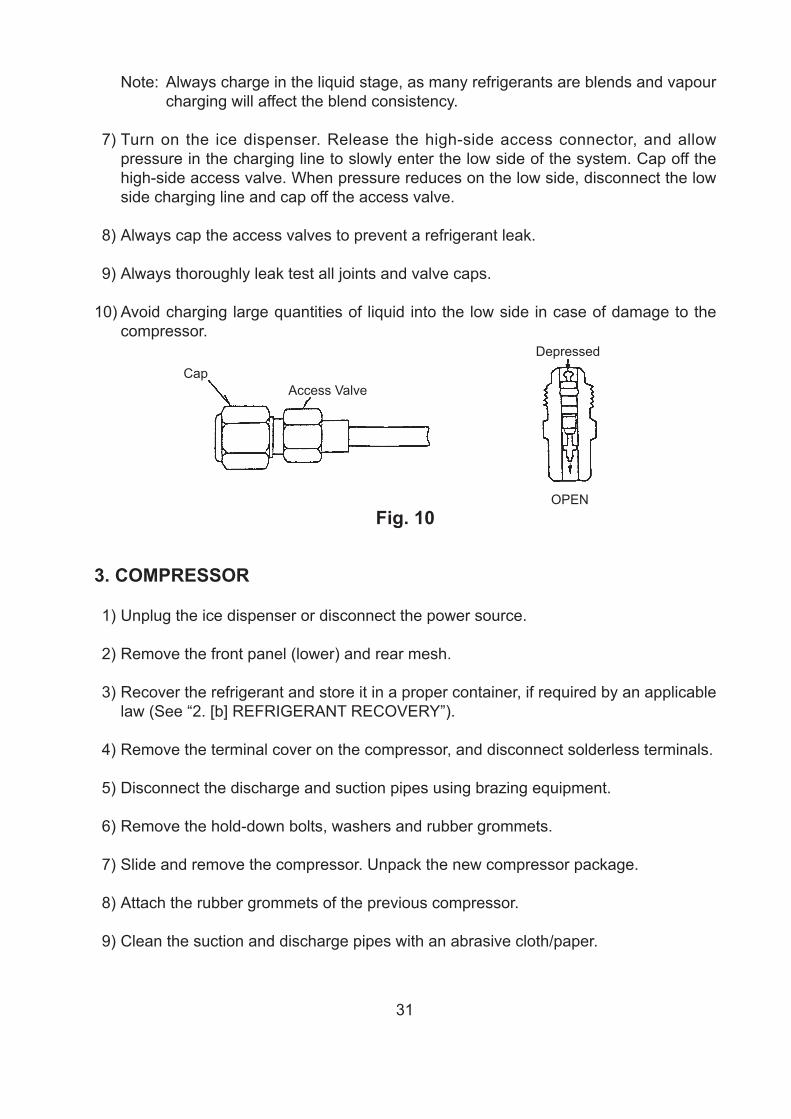
Fig. 10
CapAccess Valve
Depressed
OPEN
3. COMPRESSOR
1) Unplug the ice dispenser or disconnect the power source.
2) Remove the front panel (lower) and rear mesh.
3) Recover the refrigerant and store it in a proper container, if required by an applicable law (See “2. [b] REFRIGERANT RECOVERY”).
4) Remove the terminal cover on the compressor, and disconnect solderless terminals.
5) Disconnect the discharge and suction pipes using brazing equipment.
6) Remove the hold-down bolts, washers and rubber grommets.
7) Slide and remove the compressor. Unpack the new compressor package.
8) Attach the rubber grommets of the previous compressor.
9) Clean the suction and discharge pipes with an abrasive cloth/paper.
32
10) Place the compressor in position, and secure it using the bolts and washers.
11) Remove plugs from the compressor suction and discharge pipes.
12) Braze or solder the access, suction and discharge lines (Do not change this order), with nitrogen gas flowing at a pressure of 0.2 - 0.3 bar.
13) Install the new drier (See “4. DRIER”).
14) Check for leaks using nitrogen gas (10 bar) and soap bubbles.
15) Evacuate the system and charge it with refrigerant (See “2. [c] EVACUATION AND RECHARGE”).
16) Connect the solderless terminals and replace the terminal cover in its correct position.
17) Replace the front panel and rear mesh in their correct positions.
18) Plug in the ice dispenser or connect the power source.
Note: Hoshizaki recommends that compressor starting electrics are always replaced at the same time as the compressor.
4. DRIER
1) Unplug the ice dispenser or disconnect the power source.
2) Remove the rear mesh.
3) Recover the refrigerant and store it in a proper container, if required by an applicable law (See “2. [b] REFRIGERANT RECOVERY”).
4) Remove the drier holder, if any, and pull the drier toward you for easy service.
5) Remove the drier using brazing equipment.
6) Braze or solder the new drier, with the arrow on the drier in the direction of the refrigerant flow. Use nitrogen gas at a pressure of 0.2 - 0.3 bar when brazing tubings. Braze in an access valve using a tee if necessary.
7) Check for leaks using nitrogen gas (10 bar) and soap bubbles.
8) Evacuate the system and charge it with refrigerant (See “2. [c] EVACUATION AND RECHARGE”).
33
9) Replace the rear mesh in its correct position.
10) Plug in the ice dispenser or connect the power source.
Note: Always use a drier of the correct capacity and refrigerant type.
5. EVAPORATOR
IMPORTANT
Always install a new drier every time the sealed refrigeration system is opened. Do not replace the drier until after all other repair or replacement has been made.
1) Unplug the ice dispenser or disconnect the power source.
2) Remove the top, front (upper) and rear mesh panels.
3) Recover the refrigerant and store it in a proper container, if required by an applicable law (See “2. [b] REFRIGERANT RECOVERY”).
4) Remove the water pan assembly, referring to “7. WATER PAN ASSEMBLY.”
5) Disconnect the solder connections on the evaporator using brazing equipment.
6) Remove the four nuts holding the evaporator.
7) Install the new evaporator, and secure it with the bolts, collars (spacers) and nuts.
8) Remove and replace the drier (See “4. DRIER”).
9) Braze pipes, with nitrogen gas flowing at a pressure of 0.2 - 0.3 bar.
10) Check for leaks using nitrogen gas (10 bar) and soap bubbles.
11) Evacuate the system and charge it with refrigerant (See “2. [c] EVACUATION AND RECHARGE”).
12) Replace the panels in their correct positions.
13) Plug in the ice dispenser or connect the power source.
34
6. HOT GAS VALVE
IMPORTANT
Always install a new drier every time the sealed refrigeration system is opened. Do not replace the drier until after all other repair or replacement has been made.
1) Unplug the ice dispenser or disconnect the power source.
2) Remove the rear mesh panel.
3) Recover the refrigerant and store it in a proper container, if required by an applicable law (See “2. [b] REFRIGERANT RECOVERY”).
4) Disconnect the hot gas valve leads.
5) Remove the screw and the solenoid coil.
6) Remove the valve and drier using brazing equipment.
7) Braze the new hot gas valve with nitrogen gas flowing at a pressure of 0.2 - 0.3 bar.
WARNING
Always protect the valve body by using a damp cloth to prevent the valve from overheating. Do not braze with the valve body exceeding 120°C.
8) Install the new drier (See “4. DRIER”).
9) Check for leaks using nitrogen gas (10 bar) and soap bubbles.
10) Evacuate the system and charge it with refrigerant (See “2. [c] EVACUATION AND RECHARGE”).
11) Attach the solenoid coil to the valve body, and secure it with the screw.
12) Connect the leads.
13) Replace the panels in their correct positions.
14) Plug in the ice dispenser or connect the power source.
35
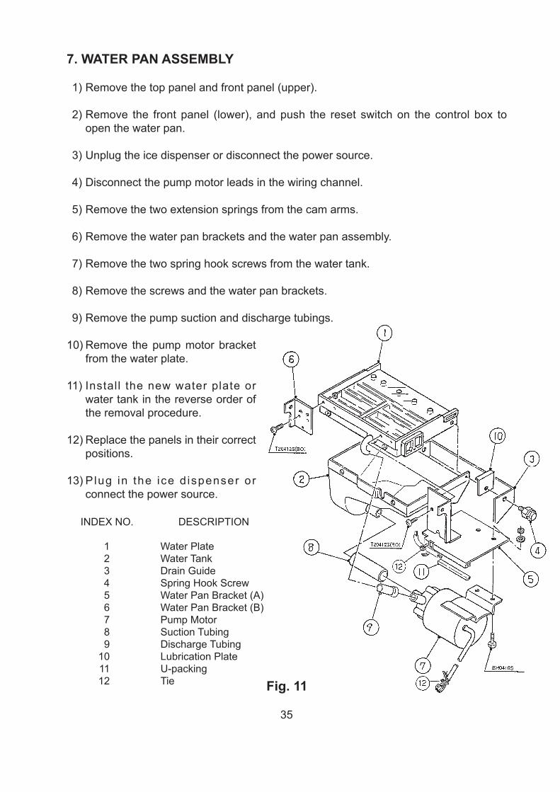
7. WATER PAN ASSEMBLY
1) Remove the top panel and front panel (upper).
2) Remove the front panel (lower), and push the reset switch on the control box to open the water pan.
3) Unplug the ice dispenser or disconnect the power source.
4) Disconnect the pump motor leads in the wiring channel.
5) Remove the two extension springs from the cam arms.
6) Remove the water pan brackets and the water pan assembly.
7) Remove the two spring hook screws from the water tank.
8) Remove the screws and the water pan brackets.
9) Remove the pump suction and discharge tubings.
10) Remove the pump motor bracket from the water plate.
11) Install the new water plate or water tank in the reverse order of the removal procedure.
12) Replace the panels in their correct positions.
13) P lug in the ice d ispenser or connect the power source.
Fig. 11
INDEX NO. DESCRIPTION
1 Water Plate 2 Water Tank 3 Drain Guide 4 Spring Hook Screw 5 Water Pan Bracket (A) 6 Water Pan Bracket (B) 7 Pump Motor 8 Suction Tubing 9 Discharge Tubing 10 Lubrication Plate 11 U-packing 12 Tie
36
8. PUMP MOTOR
1) Unplug the ice dispenser or disconnect the power source.
2) Remove the top panel and front panel (upper).
3) Disconnect the pump motor leads in the wiring channel.
4) Remove screws and the pump motor from the bracket.
5) Disconnect the pump suction and discharge tubings.
6) Disassemble the pump motor and check the motor or parts.
7) Install the new motor or parts in the reverse order of the removal procedure.
8) Plug in the ice dispenser or connect the power source, and check for leaks.
9) Replace the panels in their correct positions.
9. WATER VALVE
1) Close the water supply tap.
2) Unplug the ice dispenser or disconnect the power source.
3) Remove the top panel.
4) Disconnect the receptacle (leads) from the water valve.
5) Remove the valve outlet tubing by releasing the clamp.
6) Remove the inlet hose and water valve.
7) Install the new valve in the reverse order of the removal procedure.
8) Open the water supply tap.
9) Plug in the ice dispenser or connect the power source.
10) Check for leaks.
11) Replace the top panel in its correct position.
Note: When replacing parts, disassemble as shown in Fig. 7 (page 15) and replace the defective parts.
37
10. ACTUATOR MOTOR
1) Remove the top panel and front panel (upper).
2) Remove the front panel (lower), and push the reset switch on the control box to open the water pan.
3) Unplug the ice dispenser or disconnect the power source.
4) Remove the extension spring (actuator motor side) from the cam arm.
5) Disconnect the actuator motor leads in the wiring channel.
6) Remove the actuator motor bracket.
7) Remove the spring pin securing the shaft to the cam arm.
8) Remove the actuator motor.
9) Install the new actuator motor in the reverse order of the removal procedure.
10) Check and adjust so that the cam arm normally moves the actuator toggle switch to the “FREEZE” and “DEFROST” positions (See “II. 2. [b] BEFORE CHECKING CONTROLLER BOARD”).
11) Replace the panels in their correct positions.
12) Plug in the ice dispenser or connect the power source.
11. CAM ARM
[a] CAM ARM (A) - ACTUATOR MOTOR SIDE
Refer to “10. ACTUATOR MOTOR.”
[b] CAM ARM (B) - REAR SIDE
1) Remove the top panel and front panel (upper).
2) Remove the front panel (lower), and push the reset switch on the control box to open the water pan.
3) Unplug the ice dispenser or disconnect the power source.
4) Remove the extension spring from the cam arm (B).

38
5) Remove the split pin from the cam shaft.
6) Remove the cam arm (B).
7) Install the new cam in the reverse order of the removal procedure.
8) Replace the panels in their correct positions.
9) Plug in the ice dispenser or connect the power source.
12. ACTUATOR TOGGLE SWITCH
1) Unplug the ice dispenser or disconnect the power source.
2) Remove the top panel and front panel (upper).
3) Remove the hex nut holding the actuator toggle switch.
4) Cut off the nylon tie holding the vinyl cover bag.
5) Disconnect the receptacle of the leads.
6) Install the new actuator toggle switch in the reverse order of the removal procedure.
Note: Be sure to secure the vinyl cover bag.
7) Replace the panels in their correct positions.
8) Plug in the ice dispenser or connect the power source.
39
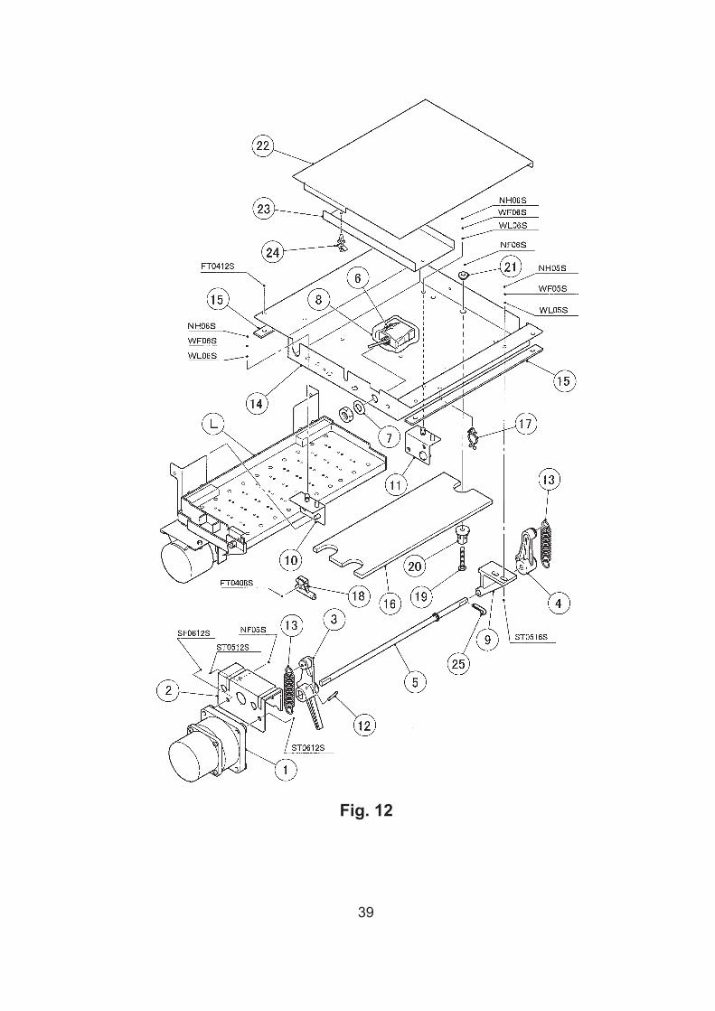
Fig. 12

40
ICEMAKING ASSEMBLY AND CAM MECHANISM
INDEX NO. DESCRIPTION
L Water Pan Assembly 1 Actuator Motor 2 Actuator Motor Bracket 3 Cam Arm (A) 4 Cam Arm (B) 5 Cam Shaft 6 Actuator Toggle Switch 7 Switch Washer 8 Switch Cover 9 Cam Shaft Holder 10 Water Pan Hanger Bracket (A) 11 Water Pan Hanger Bracket (B) 12 Spring Pin 13 Extension Spring 14 Bracket 15 Spacer 16 Insulation 17 Clamp 18 Thermistor Holder 19 Evaporator Mounting Screw 20 Spacer 21 Washer 22 Cover 23 Connector Guide 24 Board Support 25 Split Pin
13. CONTROLLER BOARD
IMPORTANT
A single type controller board is supplied as a service board. Some modifications and adjustment will be required to fit the ice dispenser models. Do not repair any parts and electronic devices on the controller board in the field. Replace the whole board with a new service board.
[a] MODIFICATION
1) Check that the service board package includes:
Controller Board 1 pc. Label 1 pc. Instruction Sheet 1 pc.
41
2) Modify the service board referring to the instruction sheet attached.
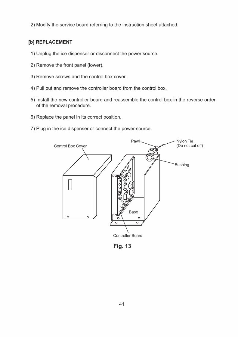
[b] REPLACEMENT
1) Unplug the ice dispenser or disconnect the power source.
2) Remove the front panel (lower).
3) Remove screws and the control box cover.
4) Pull out and remove the controller board from the control box.
5) Install the new controller board and reassemble the control box in the reverse order of the removal procedure.
6) Replace the panel in its correct position.
7) Plug in the ice dispenser or connect the power source.
Fig. 13
Control Box CoverPawl Nylon Tie (Do not cut off)
Bushing
Base
Controller Board

42
Fig. 14
Sealant
Sealant
Holder
Holder
Holder
EvaporatorScrew
* Leads* Thermistor
* Thermistor and leads are FRAGILE. HANDLE WITH CARE.
14. THERMISTOR FOR CUBE CONTROL
1) Unplug the ice dispenser or disconnect the power source.
2) Remove the top panel, front panel and pipe cover (rear).
3) Remove the connector K4 on the control ler board, referr ing to “13. [b] REPLACEMENT.”
4) Unscrew and remove the thermistor holder and thermistor, located on the evaporator (front side).
5) Install the new thermistor in the reverse order of the removal procedure, by using a sealant (high-thermal conduct type). See Fig. 14.
Note: Recommended sealant is KE4560RTV, manufactured by Shin-Etsu Silicones. When other type of sealant used, the cube size and performance will be changed. Do not use silicone sealant as this will insulate the thermistor.
43
15. FAN MOTOR
1) Unplug the ice dispenser or disconnect the power source.
2) Remove the front panel (lower).
3) Remove the control box and air guide.
4) Disconnect the connector of the fan motor.
5) Remove the fan motor bracket and the fan motor.
6) Cut the leads of the fan motor allowing enough lead length to reconnect using closed end connectors.
7) Install the new fan motor in the reverse order of the removal procedure.
8) Replace the panels in their correct positions.
9) Plug in the ice dispenser or connect the power source.
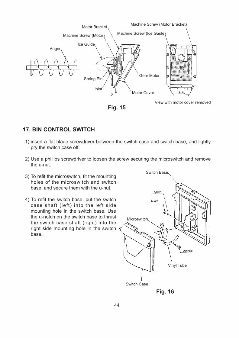
16. GEAR MOTOR
1) Press the push button to dispense all the ice in the storage bin.
2) Remove the front panels (upper) and (lower), and turn off the power switch.
3) Remove the four machine screws securing the motor bracket, and take off the gear motor together with the auger.
4) Take off the motor cover, and remove the three machine screws securing the ice guide.
5) Move the ice guide toward the auger, and remove the spring pin connecting the auger and joint.
6) Remove the four machine screws securing the gear motor, and pull out the gear motor.
7) To refit the gear motor, reverse the above procedure. Check for proper operation.
44
Fig. 15
Auger
Spring Pin
Joint
Gear Motor
Motor Cover
Motor Bracket
Machine Screw (Motor)
Ice Guide
Machine Screw (Motor Bracket)
Machine Screw (Ice Guide)
View with motor cover removed
17. BIN CONTROL SWITCH
1) insert a flat blade screwdriver between the switch case and switch base, and lightly pry the switch case off.
2) Use a phillips screwdriver to loosen the screw securing the microswitch and remove the u-nut.
3) To refit the microswitch, fit the mounting holes of the microswitch and switch base, and secure them with the u-nut.
4) To refit the switch base, put the switch case shaft ( lef t ) in to the lef t s ide mounting hole in the switch base. Use the u-notch on the switch base to thrust the switch case shaft (right) into the right side mounting hole in the switch base.
Fig. 16
Switch Base
Switch Case
Microswitch
Vinyl Tube
45
18. TRANSFORMER
1) Unplug the ice dispenser.
2) Remove the transformer cover and the transformer.
3) Cut the transformer leads at the wire connectors.
4) Install the new transformer.
5) Assemble the removed parts in the reverse order of which they were removed.
6) Plug in the ice dispenser.
19. POWER SUPPLY CORD
1) Unplug the ice dispenser.
2) Remove the front panel (upper) and front panel (lower).
3) Remove the bushing securing the power supply cord.
4) Cut the power supply cord leads at the wire connectors. Remove the earth screw.
5) Install the new power supply cord.
6) Assemble the removed parts in the reverse order of which they were removed.
7) Plug in the ice dispenser.
46
20. PUSH BUTTON SWITCH AND PILOT LAMP
1) Unplug the ice dispenser.
2) Remove the front panel (upper) and front panel (lower).
If the push button switch does not require replacement, skip 3) - 11).
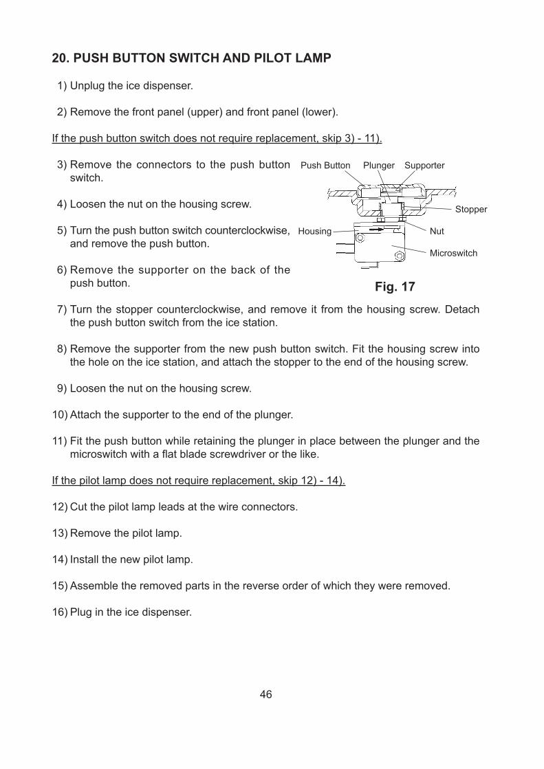
3) Remove the connectors to the push button switch.
4) Loosen the nut on the housing screw.
5) Turn the push button switch counterclockwise, and remove the push button.
6) Remove the supporter on the back of the push button.
7) Turn the stopper counterclockwise, and remove it from the housing screw. Detach the push button switch from the ice station.
8) Remove the supporter from the new push button switch. Fit the housing screw into the hole on the ice station, and attach the stopper to the end of the housing screw.
9) Loosen the nut on the housing screw.
10) Attach the supporter to the end of the plunger.
11) Fit the push button while retaining the plunger in place between the plunger and the microswitch with a flat blade screwdriver or the like.
If the pilot lamp does not require replacement, skip 12) - 14).
12) Cut the pilot lamp leads at the wire connectors.
13) Remove the pilot lamp.
14) Install the new pilot lamp.
15) Assemble the removed parts in the reverse order of which they were removed.
16) Plug in the ice dispenser.
Fig. 17
Push Button Plunger Supporter
Stopper
Housing Nut
Microswitch