Embed Size (px)
Citation preview

Project: JB3-CBS3
Thermal, Telecommunication and Power Systems
for a CubeSat
A Major Qualifying Project
Submitted to the Faculty
of
WORCESTER POLYTECHNIC INSTITUTE
in partial fulfillment of the requirements for the
Degree of Bachelor of Science
in Aerospace Engineering
By
Jennifer Hanley
Brian Joseph
Martha Miller
Samantha Monte
Joshua Trudeau
Racheal Weinrick
April 25, 2013
Prof. John Blandino, Project Advisor

i
Abstract
The objective of this project was to design the power, telecommunication, and thermal
control subsystems for an earth-orbiting CubeSat. This mission payload is an X-ray detector
designed to study solar radiation. Requirements on the spacecraft imposed by the National
Aeronautics and Space Administration (NASA) and California Polytechnic State University (Cal
Poly) were reviewed and organized to provide a reference for future design teams. The power
subsystem defined by previous Worcester Polytechnic Institute (WPI) student projects was re-
evaluated and the power budget finalized. In addition, wiring diagrams were created to show
how the power subsystem hardware interfaces with other spacecraft systems. The
telecommunication subsystem was designed in order to allow communication between the
satellite and ground stations. A ground station plan was established, including a cost budget for
hardware and identification of an existing network which could support the mission objectives.
With this information, a telecommunications link budget was created and expected ground tracks
calculated using Systems Tool Kit (STK) software. To better understand the thermal
requirements for the mission, calculations of spacecraft-sun vectors as a function of time while in
orbit were performed using STK. This data was then used to simulate such effects on the
structure using COMSOL. The report concludes with recommendations for thermal-vacuum
testing and future work with respect to these three subsystems.

ii
Acknowledgements
We would like to thank our advisor for his excellent leadership and guidance throughout our project.
Professor John J. Blandino, Ph.D. Associate Professor, Aerospace Engineering Program Department of Mechanical Engineering, Worcester Polytechnic Institute
We would also like to thank the advisors, Professors Gatsonis and Demetriou respectively for their assistance to the overall CubeSat Mission Design Project.
Professor Nikolaos Gatsonis, Ph.D. Director, Aerospace Engineering Program Department of Mechanical Engineering, Worcester Polytechnic Institute Professor Michael Demetriou, Ph.D. Professor, Aerospace Engineering Program Department of Mechanical Engineering, Worcester Polytechnic Institute
We also appreciate the collaboration with our peers who worked on the other focus groups of the CubeSat Mission Design Project.
Structural Team: Dylan Raymond Billings Ilea Shaneen Graedel Francis Stephen Hoey Peter Kendall Lavallee Justin Michael Torres ADC Team: Assaad T. Farhat Jighjigh Tersoo Ivase Ye Lu Alan Thomas Snapp We would also like to thank the correspondents who have assisted us in solving software simulation problems. Lei Chen, Ph.D. COMSOL, Inc.

iii
Authorship Our project team was divided into three subsystems: Thermal, Telecommunication and
Power. The team of Jennifer Hanley, Martha Miller, and Joshua Trudeau supplied sections
regarding the thermal subsystem. Brian Joseph, Samantha Monte, and Racheal Weinrick created
the telecommunication sections. Brian Joseph, Joshua Trudeau, and Racheal Weinrick were also
the authors of the power sections. However, due to the collaborative nature of the MQP, all
members were involved in the editing and revision of the project.
We certify this final report can be considered a group effort, with multiple partners
collaborating on each section.
_____________________________________________
Jennifer Hanley
_____________________________________________
Brian Joseph
_____________________________________________
Samantha Monte
_____________________________________________
Martha Miller
_____________________________________________
Joshua Trudeau
_____________________________________________
Racheal Weinrick
iv
Table of Contents
Abstract i
Acknowledgements ii
Authorship iii
Table of Contents iv
Table of Figures vii
List of Tables ix
List of Appendices x
Executive Summary xi
1 Introduction 1
1.1 Project Goals and Objectives 1
1.2 Power Subsystem Objectives 1
1.3 Telecommunication Subsystem Objectives 2
1.4 Thermal Subsystem Objectives 2
2 Background 3
2.1 Power Subsystem 3
2.1.1 Mechanical, Power, and Thermal CubeSat MQP 2012 [1] Final Budget 3
2.1.2 Power Subsystem Hardware 4
2.1.3 Power Subsystem Related Interface Control Document (ICD) Requirements 9
2.2 Telecommunication Subsystem 12
2.2.1 Telecommunication Subsystem Related ICD Requirements 12
2.2.2 Hardware 13
2.2.3 Ground stations 17
2.3 Thermal Subsystem 20
2.3.1 Thermal Control Related ICD Requirements 20
2.3.2 Analyses Required 20
2.3.3 Active/Passive Thermal Control Methods 25
3 Methodology 27
3.1 Power Subsystem Distribution 27
3.1.1 Telemetry Communication 29
v
3.1.2 EPS Switch Configuration 30
3.2 Telecommunication Subsystem 31
3.2.1 Implementation of Telecommunication Subsystem Hardware 31
3.2.2 Ground Station Network 33
3.2.3 STK Analysis 39
3.3 Thermal Subsystem 42
3.3.1 Thermal Analysis from External Sources 42
3.3.2 STK Analysis 44
3.3.3 Vacuum Modeling in COMSOL 46
3.3.4 Lab Option in Vacuum Chamber 48
3.3.5 Thermal Control System 49
4 Results 51
4.1 Power Subsystem 51
4.1.1 Power Subsystem Hardware, Monetary and Power Budget 51
4.1.2 Wiring Results 54
4.2 Telecommunication Subsystem 55
4.2.1 Mission Modeling and Timelines 55
4.2.2 Communication Hardware 59
4.3 Thermal Subsystem 60
4.3.1 COMSOL Analysis Results 60
4.3.2 Thermal Analysis from External Sources 65
5 Conclusions and Recommendations 69
5.1 Power Subsystem 69
5.2 Telecommunication Subsystem 69
5.2.1 Hardware Testing Recommendations 69
5.2.2 WPI Ground Station Proposal 71
5.3 Thermal Subsystem 71
5.3.1 Recommendations Based on Vacuum Thermal Analysis 71
5.3.2 Lab Option 72
5.3.3 Thermal Control System 73
Works Cited 74

vi
Appendices 80
Appendix 1: Requirements per Reference Documents 80
Appendix 2: Definition of Key Terms 92
Appendix 3: Normalized Beta Values over 24 Hours at 5 minute Step 95
Appendix 4: Lab Option Hardware List 96
Appendix 5: WPI Ground Station 98
Appendix 6: Other Ground Station Hardware 100
Appendix 7: Complete Hardware Parts List with Images 103
Appendix 8: CubeSat Bus Wiring Diagrams 108
Appendix 9: CubeSat Bus Power Board Pin Assignments 112
Appendix 10: On Board Computer (OBC) [64] 120

vii
Table of Figures Figure 1: Power Subsystem ............................................................................................................ 5 Figure 2: Solar panel output as a function of temperature [5]. ....................................................... 6 Figure 3: Clyde-Space 3U EPS [6]. ................................................................................................ 7 Figure 4: Clyde-Space PDM [7]. .................................................................................................... 8 Figure 5: Location of Deployment Switches [2](2011) ................................................................ 10 Figure 6: Location of Access Port for 3U CubeSat [2] (2011) ..................................................... 11 Figure 7: Telecommunications subsystem .................................................................................... 14 Figure 8: ISIS deployable antenna [9] .......................................................................................... 16 Figure 9: ISIS UHF/VHF transceiver [10].................................................................................... 17 Figure 10: P-POD and CubeSat Environment Tests (Thermal) (2011) [3] .................................. 22 Figure 11: Thermal Vacuum Bakeout Profile [2] (2004) ............................................................. 24 Figure 12: Possible Configuration of Pull Pin and Separation Switches (adapted from [6]) ....... 30 Figure 13: Ground track with ground stations .............................................................................. 35 Figure 14: Access Report .............................................................................................................. 36 Figure 15: Link Budget ................................................................................................................. 37 Figure 16: Access Report for the Four selected Ground Stations ................................................. 38 Figure 17: Ground tracks of the CubeSat plotted using STK. ...................................................... 39 Figure 18: Ground track showing location of satellite connected to two ground stations (Delft and Warsaw). ................................................................................................................................ 41 Figure 21: (Left) 3D cube at time t=0 sec & (Right) 3D cube at time t=172800 sec ................... 44 Figure 22: CubeSat Axes [1]......................................................................................................... 45 Figure 23: CubeSat-Sun Vector .................................................................................................... 46 Figure 24: Aluminum Skeleton for Lab Option (2012) [1] .......................................................... 47 Figure 25: Total expected daily access time as a function of launch date. ................................... 56 Figure 26: Expected daily downlink access at each ground station as a function of launch date. 57 Figure 27: Expected daily uplink access at each ground station as a function of launch date. .... 57 Figure 28: Vacuum Chamber Model ............................................................................................ 61 Figure 29: Temperature vs. Coordinate X, Y, Z ........................................................................... 63 Figure 30: Radiosity vs. Coordinate X ......................................................................................... 63 Figure 31: Radiosity vs. Coordinate Y ......................................................................................... 64 Figure 32: Radiosity vs. Coordinate Z .......................................................................................... 64 Figure 33: Mesh for External Components ................................................................................... 67 Figure 34: Temperature vs. Time over 3 orbits. ........................................................................... 68 Figure 35: Basic setup showing ISIS transceiver © 2012 isispace.nl (Left), bench-top variable signal attenuator © 2012 jfwindustries.com (Middle) and ICOM radio © 2012 icomamerica.com (Right) [10] [33] ............................................................................................................................ 70 Figure 36: Vertical Board Stack (Side Images of boards adapted from [7], [6] and [26]) ......... 108 Figure 37: CubeSat Bus's Pin and Header Labeling ................................................................... 108 Figure 38: Solar Array Wire Labeling (adapted from [6]) ......................................................... 109

viii
Figure 39: SA Connector Location and Labeling (adapted from [6]) ........................................ 109 Figure 40: SA Connector Pin Labeling (adapted from [6]) ........................................................ 110 Figure 41: Gyroscope's Mounting Board Wire Connection Labeling (adapted from [61]) ........ 110 Figure 42: Magnetometer's Mounting Board Wire Connection Labeling (adapted from [62]) .. 111 Figure 43: Coarse Sun Sensor's Wire Labeling (adapted from [21]) .......................................... 111 Figure 44: GPS's Wire Labeling (adapted from [63]) ................................................................. 111

ix
List of Tables Table 1: Final Power Budget from 2012 AE CubeSat MQP [1]. ................................................... 3 Table 2: Preliminary 10 Ground Station Locations ...................................................................... 34 Table 3: Final Ground Station Locations ...................................................................................... 37 Table 4: Lab Option Materials Purchased .................................................................................... 48 Table 5: Operational Temperatures .............................................................................................. 49 Table 6: Updated Power Budget ................................................................................................... 52 Table 7: Power Hardware Costs ................................................................................................... 53 Table 8: Key parameters in data rate calculation and expected data values. ................................ 59 Table 9: CubeSat Bus, Header 1 ................................................................................................. 112 Table 10: CubeSat Bus, Header 2 ............................................................................................... 114 Table 11: Device Connection Information ................................................................................. 117

x
List of Appendices Appendix 1: Requirements per Reference Documents ................................................................. 80 Appendix 2: Definition of Key Terms .......................................................................................... 92 Appendix 3: Normalized Beta Values over 24 Hours at 5 minute Step ....................................... 95 Appendix 4: Lab Option Hardware List ....................................................................................... 96 Appendix 5: WPI Ground Station ................................................................................................. 98 Appendix 6: Other Ground Station Hardware ............................................................................ 100 Appendix 7: Complete Hardware Parts List with Images .......................................................... 103 Appendix 8: CubeSat Bus Wiring Diagrams .............................................................................. 108 Appendix 9: CubeSat Bus Power Board Pin Assignments ......................................................... 112 Appendix 10: On Board Computer (OBC) [64] ......................................................................... 120

xi
Executive Summary The CubeSat Design Project began in 2010; since then the design process is well
underway working toward funding and an eventual launch in the near future. The Mechanical, Power, and Thermal CubeSat Major Qualifying Project (MQP) 2012 [1] worked to create a preliminary hardware selection and created a model in COMSOL Multiphysics (Burlington, Ma.) for internal, external, and “Lab Option” simulations. This year, the project got even closer to reality through hardware finalization and breaking ground in the telecommunication subsystem.
Due to the cost of such a project and other CubeSat missions already in space, there many reference documents specifying requirements for launch and mission operations. A thorough review of documentation and research related to existing CubeSat missions revealed that a CubeSat mission must follow specifications given by the following institutions: California Polytechnic State University (Cal Poly) [2], National Aeronautics Space Association (NASA) [3], and the United States Air Force (USAF) [4]. The necessary requirements were compiled for future design teams’ reference.
Within the power subsystem there was an existing power budget to ensure there will always be enough power supplied to all hardware within the CubeSat. As changes were made to on-board hardware, the budget was updated with the respective required power supply data. As the hardware for all other subsystems became finalized, the requirements for the power supply system became clearer, and therefore helped to finalize the power subsystem hardware. The wiring for power supply was defined in detail and shared with the CubeSat Structural team.
Telecommunications on-board and between the CubeSat and ground station were investigated for the first time in the CubeSat Design process. Ground stations were researched to determine the best hardware and ground station network for a successful CubeSat mission. It was determined that joining the Global Educational Network for Satellite Operations (GENSO) would be an effective way to become part of an established network in a relatively short time. Creating a link and access budget using System Tools Kit (STK) (AGI, Exton, Pa.) was crucial in choosing the ground station hardware. A monetary budget for the on-board and ground station hardware was also created to prepare a Worcester Polytechnic Institute (WPI) Ground Station proposal.
The thermal subsystem maintains the spacecraft temperature within acceptable limits. The group evaluating this subsystem was responsible for conducting thermal analysis for the CubeSat within the space environment and in the vacuum chamber. Spacecraft-sun vectors were calculated using STK and imported into COMSOL for external component analysis to generate more accurate results. Continuing with the Lab Option from last year’s MQP team, a procedure of the vacuum chamber test was written. A model was generated in COMSOL to compare results from the thermal analysis to the vacuum chamber test

1 Introduction
1.1 Project Goals and Objectives
The goal of the CubeSat project is to provide a sufficient definition of the spacecraft and
mission to support a proposal for a CubeSat Mission to fly the SphinX-NG X-ray solar flux
detector. The focus of this team is on three subsystems of the CubeSat: the power subsystem, the
telecommunication subsystem, and the thermal subsystem. The objectives of the project are to
confidently show how each subsystem will work in the CubeSat, and provide the necessary
analysis and hardware recommendations for the actual systems to be created. For the spacecraft
to be eventually approved for launch, the CubeSat must be able to meet all requirements stated
by the involved parties. These include standards for testing set forth by National Aeronautics
Space Association (NASA) [3], California Polytechnic State University (Cal Poly) [2], and
Department of Defense standards [4]. This team was responsible for understanding and creating
procedures for these requirements, so that the CubeSat Mission could be approved.
1.2 Power Subsystem Objectives
Power subsystems are used to produce, condition, store, and distribute power to various
devices throughout the CubeSat. There were two primary objectives for the power subsystem.
The first objective was to build upon last year’s work and have an updated power budget, to
ensure that the payload and all CubeSat subsystems have the power they need at all times [1].
The second objective was to detail the wiring of all the power subsystem circuit boards and the
CubeSat devices (i.e. “power consumers”), to ensure that everything was connected and could
receive power, as well as relay information to the controlling CubeSat On-Board Computer
(OBC).
2
1.3 Telecommunication Subsystem Objectives
The CubeSat requires communication between earth and itself. Telecommunication
subsystems are used to relay commands and data to and from the CubeSat and ground stations on
Earth. To make sure this was possible for the CubeSat, this team was responsible for three
primary objectives. The first was to determine, using Systems Tool Kit (STK), the extent of
ground coverage the CubeSat would have access to through the use of various ground stations.
The second objective was to define a data link budget based upon the extent of ground coverage
as well as the CubeSat telecommunication hardware. The third objective was to identify and
recommend hardware to be used in the CubeSat Mission.
1.4 Thermal Subsystem Objectives
The thermal control subsystem ensures the CubeSat does not exceed the maximum and
minimum operational temperatures of its components. With that in mind, this year’s team was
responsible for two primary objectives. The first objective was to refine last year’s thermal
analysis by using STK to determine the angles at which the sun strikes the CubeSat and then use
those values in COMSOL to produce a more detailed thermal modeling of the CubeSat as it
orbits the Earth [1]. Using this data, an analysis can be performed to determine a recommended
thermal control method. The second objective was to test a model of the CubeSat in the
Worcester Polytechnic Institute (WPI) vacuum chamber for comparison to the COMSOL
analysis in order to verify the findings.

3
2 Background
2.1 Power Subsystem
2.1.1 Mechanical, Power, and Thermal CubeSat MQP 2012 [1] Final Budget
Power is one of the most important considerations when planning a CubeSat mission. If
the power budget was incorrect or the power system shorted out, the entire mission would be
compromised. The 2011-2012 Major Qualifying Project (MQP) team [1]created a power budget
based on the instruments selected and the information available at the end of the project. Table 1
below shows the final power budget proposed by the 2011-2012 teams.
Table 1: Final Power Budget from 2012 AE CubeSat MQP [1].

4
This was a preliminary power budget that does not include all necessary information to
properly estimate available power. Even though the numbers in Table 1 are based on data from
the manufacturer, these numbers will be tested by future groups once the hardware is acquired.
These tests will verify the hardware to make sure they do not deviate from manufacturer values.
For values listed as To Be Determined (TBD), a manufacturers value will be inserted and
verified to make certain there will be enough power for the CubeSat. Once the current values
have been verified and the budget has been updated, the flight will then be broken down into the
different phases of the mission which will each have their own power budgets based on
instrument usage.
2.1.2 Power Subsystem Hardware
Power is a key element of CubeSat design and can be the determining factor in lifetime of
the CubeSat. The goal of the power subsystem is threefold:
1. To generate and/or store power for the CubeSat
2. To condition and distribute power for the CubeSat
3. To protect the CubeSat in the case of a fault
In the majority of CubeSats that have been launched, the first goal is accomplished with
the use of solar arrays in combination with a battery giving the satellite power while in view of
the sun or from albedo radiation and retaining power in the battery for peak loads and while in
eclipse. The second goal is accomplished through the use of power management and distribution
(PMAD) modules. These modules ensure that the power is supplied to users throughout the
CubeSat and that the power is properly conditioned. The final goal is accomplished through the
use of regulators and safeguards within the PMAD modules that monitor current flows to prevent
damage to other components. The PMAD modules should also be able to function if the OBC

5
were to malfunction or need to be rebooted in order for the CubeSat to continuously have power
once it exits the Poly-Picosatellite Orbital Deployer (P-POD). An overview of the power
subsystem is shown by the flowchart in Figure 1.
Figure 1: Power Subsystem
Solar Array
Power generation duties on CubeSats are covered by solar arrays due to the abundant
solar energy available in orbit; there is over four times the energy available to satellites
compared to ground based panels. As such, the panels used on CubeSats are small and light
while still providing plenty of power to users. Many solar panels designed for operation in space
use gallium arsenide cells because of its higher efficiency compared to silicon, and a lightweight
substrate made of fiberglass Printed Circuit Board (PCB), aluminum, carbon fiber or an
alternative composite.

6
The power level generated by the cells is a function of their efficiency, area, cell density,
and temperature. While the physical qualities of the panels are only affected by degradation over
time, temperature of the panels is far from constant and as a result the panels must be optimized
for specific temperatures. Furthermore, as can be seen in Figure 2, solar cells operate more
efficiently at lower temperatures and produce a higher peak voltage, so heat should be dissipated
from the panels as quickly as possible. Note that there is an optimal point for a given temperature
where power is highest. This is the peak power point.
Figure 2: Solar panel output as a function of temperature [5].
The 2011-2012 MQP team chose to use a three panel system for the power generation
needs; the system consists of a front mounted Two Unit (2U) panel and two single-deployed 2U
panels on the sides as shown in Figure 2 [1].
7
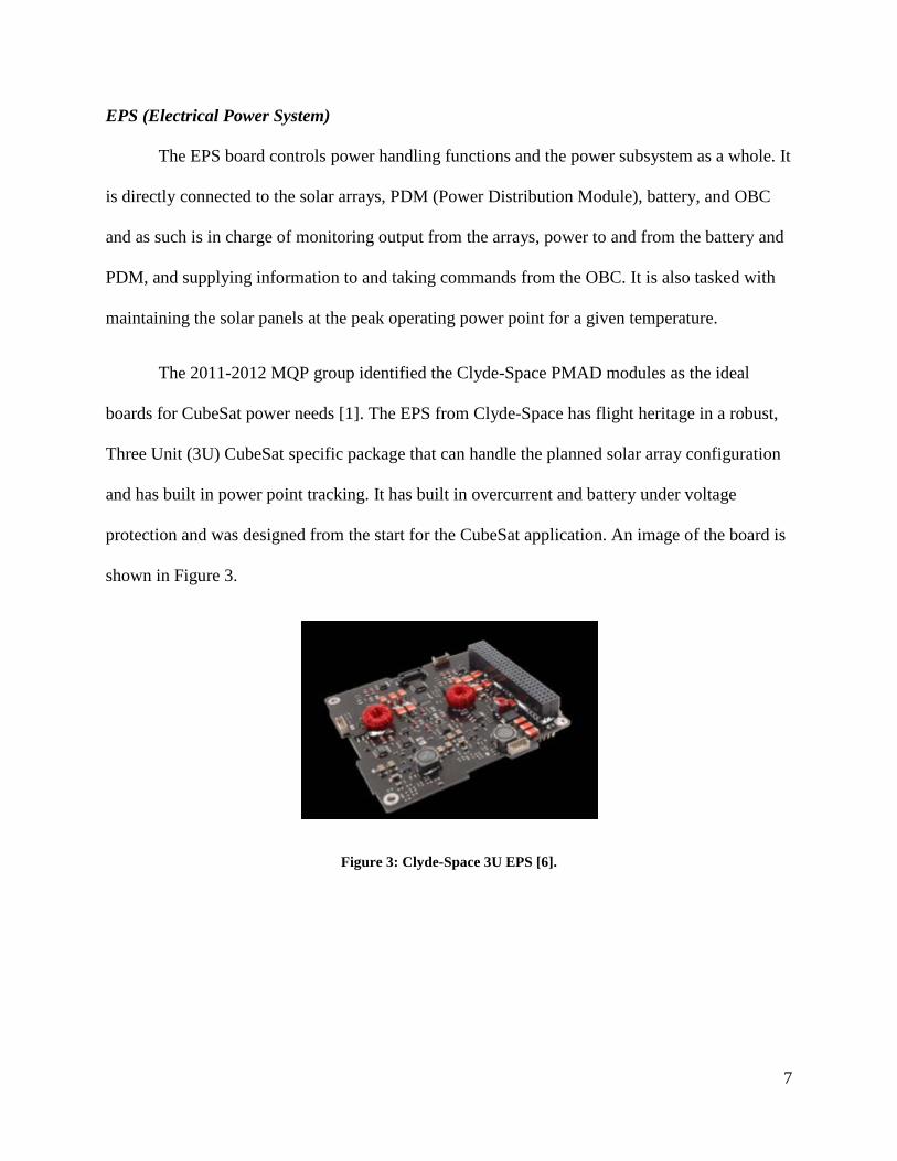
EPS (Electrical Power System)
The EPS board controls power handling functions and the power subsystem as a whole. It
is directly connected to the solar arrays, PDM (Power Distribution Module), battery, and OBC
and as such is in charge of monitoring output from the arrays, power to and from the battery and
PDM, and supplying information to and taking commands from the OBC. It is also tasked with
maintaining the solar panels at the peak operating power point for a given temperature.
The 2011-2012 MQP group identified the Clyde-Space PMAD modules as the ideal
boards for CubeSat power needs [1]. The EPS from Clyde-Space has flight heritage in a robust,
Three Unit (3U) CubeSat specific package that can handle the planned solar array configuration
and has built in power point tracking. It has built in overcurrent and battery under voltage
protection and was designed from the start for the CubeSat application. An image of the board is
shown in Figure 3.
Figure 3: Clyde-Space 3U EPS [6].

8
PDM (Power Distribution Module)
The PDM distributes power to users along specific power busses, which are connectors
supplying power and data to all the electronics in the CubeSat. It includes the ability to switch
different users on and off, along with protection for every circuit. Power is provided by the EPS,
whether the satellite is running on battery power alone, a mix of array and battery power, or the
arrays alone. The PDM also utilizes overcurrent protection on every circuit to protect users. The
Clyde-Space PDM board is shown in Figure 4. It is designed to integrate directly with the EPS
and has the same form-factor.
Figure 4: Clyde-Space PDM [7].
Battery
Batteries supplement the energy output from the solar arrays at peak usage while also
providing power while in eclipse. Lithium ion or lithium polymer cells are commonly used for
their characteristically high energy density compared to alternative cells. Unfortunately, lithium
ion or polymer batteries tend to become unstable near their extreme operating temperatures, so it
is imperative that the batteries are constantly monitored to avoid loss of the batteries or worse.
These batteries can only handle a finite number of charge and discharge cycles before failure,
usually in the range of as few as 50 cycles up to thousands of cycles depending on the battery

9
specification. To maximize battery life it is important to properly budget power so the battery
never exceeds the recommended depth of discharge, which is 20% to 30% for most CubeSat
batteries. While more battery cells could be added for redundancy and to offset power
requirements, it should be noted that batteries incur a high cost in both weight and volume.
Despite these limitations, batteries are necessary on most CubeSat missions and play an
important role in the power system maintaining power in eclipse and supplementing power at
times when need exceeds that produced by the solar panels.
2.1.3 Power Subsystem Related Interface Control Document (ICD) Requirements
The requirements outlined in the document supplied by Cal Poly San Luis Obispo [2]
stipulate that no electronics shall be active during launch. This is to prevent any interference,
either from electrical or RF sources with the launch vehicle and primary payloads. The CubeSat
must also have a Remove Before Flight (RBF) pin. The RBF pin when installed must cut all
power to the CubeSat bus, and must be removed after the CubeSat is integrated with the P-POD.
If a RBF pin is not present, the satellite must launch with its batteries fully discharged. The
CubeSat must also have at least one deployment switch located on the -z face of the CubeSat as
shown in Figure 5. The deployment switch must keep the satellite powered off while it is
actuated. Once the satellite is deployed, the deployment switch will no longer be actuated and
this will start the deployment timer. The deployment timer requirement is a separate requirement
from the deployment switch. It ensures that no mechanical structures or appendages are deployed
until 30 minutes after the satellite is ejected from the P-POD. It also ensures that no
transmissions are generated until 45 minutes after the satellite is ejected from the P-POD. The
deployment switch must also be able to reset the deployment timer if the switch is toggled from
the actuated state and then actuated again. After the CubeSat is loaded into the P-POD, it can

10
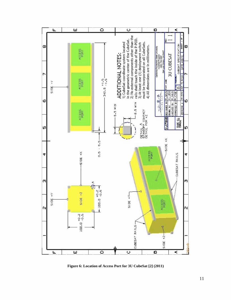
then be charged through access ports located on the P-POD as shown in Figure 6. However, the
total stored energy in the battery after charging must be no more than 100 Watt hours. As the
CubeSat has a battery onboard, the CubeSat must also be capable of receiving a command to
shut down the transmitter.
Figure 5: Location of Deployment Switches [2](2011)
11
Figure 6: Location of Access Port for 3U CubeSat [2] (2011)

12
The CubeSat shall also be self-contained, providing its own power, sequencing and
wiring [3]. The requirement of the CubeSat being able to provide its own sequencing refers to it
being able to carry out its tasks without constant commands from a ground station. The electrical
wiring of the satellite, specifically its insulation, shall also be inspected for flammability prior to
its launch [3]. If the wire insulation is chemically and physically similar to a material found to be
acceptable by NASA-STD-(I)-6001, then the material may be used without testing and justified
on an approved Material Usage Agreement (MUA). After the thermal vacuum bakeout test is
performed, the electrical functionality of the satellite needs to be re-verified [3].
NASA requires the CubeSat also have an End of Mission (EOM) plan [8]. Prior to the
EOM the satellite needs to be pacified for earth orbit or earth reentry. The passivation of the
satellite will entail the removal of all forms of stored energy. It must be depleted to a point where
it would be insufficient to cause a breakup of the satellite. The electrical systems, specifically the
batteries and the charging circuits shall be part of the passivity analysis.
2.2 Telecommunication Subsystem
2.2.1 Telecommunication Subsystem Related ICD Requirements
In recent years, CubeSat launches have become more common. With this increase, the
potential problems that may be encountered have become more clear, but also preventable.
Requirements for sending a CubeSat into space have been established and continuously updated
by a variety of authors. For the 3U CubeSat under study for this project, the required
specifications are given by Cal Poly, NASA, and the USAF. A full list of CubeSat applicable
mandates can be found in Appendix 1. These documents create a profile for the size and shape
of a CubeSat, along with restrictions to prevent any perturbations to the Launch Vehicle (LV) or

13
other satellites already in orbit. There is an orbital verification process which reviews the
mission flight plans in order to prevent collisions and ejection conflicts. Frequency restrictions
during the mission are put in place to prevent radio interference between the LV and other
satellites. A frequency application must be filled out, approved, and a license issued for a
specific frequency to be used for communication between the satellite and ground station. It has
become necessary to have requirements that ensure redundancy in place, so that in the event of
error or failure there are back-up commands in place. Another command prerequisite is to make
sure the CubeSat has the capability for Global Positioning System (GPS) tracking and real-time
on board system updates to assure the hardware is working correctly. Requirements are in place
to assure that all Commercial Off-the-Shelf (COTS) hardware used is in accordance with all the
NASA and Cal Poly standards. There are LV requirements to assure the CubeSat is installed
correctly onto the LV. This means that the CubeSat must meet vibration testing limits, and
assures that the satellite does not interfere physically or electronically with the mission of the
LV. These requirements also demand any testing that will assure the CubeSat’s ejection from
the LV goes smoothly. These tests include, but are not limited to, testing the CubeSat switch to
ensure the power stays off and that the ejection portion of the mission plan will not interfere with
the LV’s mission or the LV physically.
2.2.2 Hardware
The purpose of the telecommunications system in a CubeSat is to provide a link between
the OBC and ground operations. This is necessary for two reasons:
1. To satisfy the mission requirements for retrieving instrument data.
2. To satisfy the mission requirements for telemetry, tracking, and command.

14
A CubeSat is only as good as the information it provides to the organizations sending it
into orbit. Information stored on a CubeSat does no good until it is transmitted to ground stations
by some means. This is achieved through radios operating under Ultra High Frequency (UHF),
Very High Frequency (VHF), or S-band1 specifications which communicate with ground
networks. The full system is composed of two main elements; the transceiver, which is the radio
itself, and an antenna that tunes the radio’s signal. Data handling and compression are also a part
of the telecommunications system. A representation of the system is shown below in Figure 7.
Figure 7: Telecommunications subsystem
The main driving factors in specifying telecommunications components are data rates,
reliability of data delivery, and power consumption. Data rates are driven by instrument data
requirements and are a function of signal sampling rate and bit rates. The reliability of the system
is based on the robustness of the physical components along with correct specification of
frequency bands and compression algorithms. Data is transferred by the use of packets, which
are strings of data including control and user information. Packets received from the CubeSat
should be able to be salvaged if incomplete; otherwise the packet would need to be resent,
1 Frequency ranges for VHF, UHF, and S bands are as follows: VHF = 30-300MHz, UHF = 300-3000MHz, S-Band = 2-4GHz

15
costing precious downlink time. Finally, power consumption plays a key role as the radio is a
comparatively large power draw, at up to 1.5W.
An important aspect of the telecommunications system is the ability of ground stations to
monitor telemetry, track, and command the CubeSat. Various telemetry measurements taken by
the OBC verify that the CubeSat is functioning properly and if not can give clues as to why a
part is malfunctioning. Tracking provides verification of the CubeSat’s position and trajectory by
analyzing the time delay in sent and received packets. Finally, command functions allow the
ground operations to access different modes of the CubeSat or address immediate problems.
Antenna
CubeSat antennas are optimized for small size and low mass while integrating with
available UHF, VHF, or S-band transceivers. Two common antenna designs for CubeSats are
patch antennas which affix to a side of the CubeSat and are little more than a thin, flat PCB with
an imbedded antenna and deployable tape spring antennas which are affixed to a standard base
and spring outwards from recesses in the CubeSat. An example of an ISIS deployable antenna
system being considered for the current proposal can be seen below.

16
Figure 8: ISIS deployable antenna [9]
The common antenna types seeing use on CubeSats in the aforementioned configurations
are monopoles, dipoles, and turnstiles. A monopole takes the form of a single radiating wire with
a low gain and nearly spherical radiation profile. This makes it favorable for systems with low
complexity and little to no pointing ability. The dipole and turnstile antenna types are comprised
of 2 and 4 monopoles, respectively, which boosts antenna gain at the expense of more directional
radiation profiles.
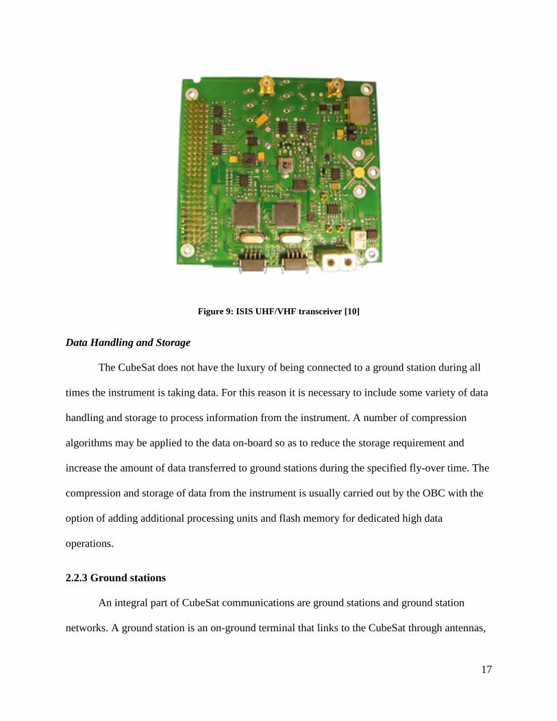
Transceiver
A transceiver is a single board housing both a transmitter and receiver circuit. The
transceiver converts data from the OBC into a form that can be sent to ground stations via a
carrier signal. The most common Transceivers for CubeSats operate in both the UHF and VHF
bands. This allows the use of the VHF band for downlink and UHF band for uplink or vice-
versa.
17
Figure 9: ISIS UHF/VHF transceiver [10]
Data Handling and Storage
The CubeSat does not have the luxury of being connected to a ground station during all
times the instrument is taking data. For this reason it is necessary to include some variety of data
handling and storage to process information from the instrument. A number of compression
algorithms may be applied to the data on-board so as to reduce the storage requirement and
increase the amount of data transferred to ground stations during the specified fly-over time. The
compression and storage of data from the instrument is usually carried out by the OBC with the
option of adding additional processing units and flash memory for dedicated high data
operations.
2.2.3 Ground stations
An integral part of CubeSat communications are ground stations and ground station
networks. A ground station is an on-ground terminal that links to the CubeSat through antennas,
18
transmitter, receiver, and control equipment to transmit and receive messages, track, or control
the satellite [11]. Ground stations are located all around the Earth in a series of networks or
within the atmosphere, such as using other satellites to communicate. There are different uses for
ground stations: telecommunication with satellites, communication with space stations or space
probes, or tracking. The earth stations use radio waves in super high frequency or extremely high
frequency bands, with a frequency band of 3 GHz to 30 GHz for Super High Frequency (SHF)
and 30 GHz to 300 GHz for Extremely High Frequency (EHF) [12].
When the station successfully transmits these radio waves a telecommunications link is
established. A link is the communications channel that connects two or more communicating
devices. There are several different types of telecommunication links: uplink, downlink, forward
link, and reverse link. An uplink is the transmission between the earth terminal and the satellite.
It is the inverse of the downlink, which is the link from the CubeSat to the ground station. A
forward link is the link from a fixed location, such as a base station, to a mobile user. A forward
link will contain an uplink, base station to satellite, and downlink, satellite to mobile user, if a
communications relay satellite is involved. A reverse link is the link from a mobile user to a
fixed base station. In the case of a communications relay satellite, the reverse link will have both
an uplink, mobile station to satellite, and a downlink, satellite to base station [12]. A crosslink is
the link between a satellite and another satellite. These links are part of a larger network within
the ground station, a telecommunications network. This network is created through a collection
of terminals, links, and nodes that all connect to ensure telecommunication between terminals
and ground stations. A unique address is created for each terminal in the network so messages
will be sent correctly. Address space is the collection of these unique addresses in each network.

19
The geometry of the links and the ground station create the telecommunication
architecture. There are different types of architectures, each with their own advantages and
disadvantages. “Store and forward” is an architecture for relaying communications by satellite.
For this, the satellite orbits at a low altitude and receives data that is stored in its memory. The
data is transmitted when the satellite is in view of a receiver ground station. The advantages of
this architecture are that a low-cost launch vehicle and low cost satellite can be used due to the
low altitude and wider antenna beam width which reduces the satellite antenna size and
stabilization requirement. The disadvantage is there is a long message access time and
transmission delay since they are waiting for the satellite to pass into view [13].
Geostationary orbit is used by communication relay satellite systems and meteorological
satellites. The satellite is placed in a near-zero degree inclination orbit at about 36,000 km
altitude. The orbit of the satellite is equal to the period of Earth’s rotation which is one of its
advantages. The cost of a ground station is less because there is no need for antenna pointing
control so it is a stationary network. A stationary network is easier to set up, monitor, control,
and there is no need to switch satellites since the satellite is always in view. The disadvantage is
the lack of coverage above 70 degree latitude and the high launch cost. There is also a delay time
for propagation to and from the orbit which can cause problems [13].
A Molniya orbit is used to cover the northern Polar Regions with the satellites in highly
elliptical orbits. The specification for the orbit is an apogee of 40,000 km (which is over the
North Pole), a perigee of 500 km, and an inclination angle of 63.4 degree. The period of the orbit
is 12 hours and since the orbit is highly elliptical, the satellite spends about 8 hours of each
period over the northern hemisphere. A disadvantage of this geometry is that there is a
continuous change of antenna positioning and switching links between satellites [13].

20
Geostationary orbit with crosslink is an architecture used when a geostationary satellite is
beyond the line of sight of a ground station and a secondary satellite relays data to the ground
station. A relay satellite is better than using two adjacent ground stations because the adjacent
ground station is on foreign territory. Since it is on foreign territory there is more cost and the
transmission is less secure and less survivable. The disadvantage of the relay satellite is it
increases the architecture’s complexity, risk, and cost [13].
2.3 Thermal Subsystem
2.3.1 Thermal Control Related ICD Requirements
A thermal vacuum bakeout test must be performed to ensure acceptable levels of
component outgassing [2]. Outgassing is the release of volatiles (gas or vapor) that has been
dissolved, trapped or absorbed in a material. The thermal vacuum bakeout test entails the
CubeSat being placed in a high vacuum level of a minimum of 10-4 Torr and exposed to either
70 °C for 3 hours or 60 °C for 6 hours. The satellite must also be able to survive the temperatures
of its environment (both during the launch and in space). The launch condition temperatures
range from 1.7 °C to 37.8 °C and the thermal environment temperatures during its powered flight
range from 7.0°C to 55.1°C [2]. The thermal environment the CubeSat will encounter should be
considered for the two extreme cases where the satellite is fully lit by the sun and when the
satellite is in an eclipse.
2.3.2 Analyses Required
The CubeSat needs to survive in the harsh space environment, which depending on the
position of the satellite can be either extremely hot or cold. The thermal control system needs to
keep the temperature within the allowable thermal limits of all components. This is why there is

21
a series of mandatory analyses and tests before CubeSat can be launched. The GSFC-STD-7000
reference document provides a table of requirements that must be met for different levels of
assembly as well as identifying if analysis or testing is necessary [14]. It also outlines the
requirements for each test: providing special considerations, demonstrations, and acceptance
requirements. The table in Appendix 1 from the GSFC-STD-7000 document presents the
vacuum, thermal, and humidity requirements.
According to the table, testing is required for all levels of assembly to meet the Thermal-
Vacuum requirements as listed. For Thermal Balance, testing and analysis is required for
payload or highest level of assembly, a completely assembled space craft [14]. If analysis
verification is provided for subsystems and components, testing is not required at these levels of
assembly. The CubeSat will not have any devices that contain fluids, so Temperature-Humidity
and Leakage analysis and testing will not be required.
There are two vacuum tests that must be performed before launching the CubeSat:
Thermal Vacuum Cycle and Thermal Vacuum Bakeout. According to the table included in the
DNEPR2 Safety Compliance Requirements reference document, the P-POD must go through
both tests whereas the CubeSat must be tested in the Thermal Vacuum Bakeout [14]. For each
test, the CubeSat and P-POD must undergo a protoflight and acceptance test. A list of
requirements per test is in Figure 103. The components are tested at safe levels to ensure they
work.
2 DNEPR is a Russian launch vehicle. It carried 14 CubeSats to be launched into space but failed to launch. [66] 3 Protoflight test levels are the same as qualification levels. They are performed on prototype components at extreme levels, nearly 1.4 times over the operating loads of the components [65]. Acceptance test levels are performed when the CubeSat passes the qualification and protoflight tests [65].

22
Figure 10: P-POD and CubeSat Environment Tests (Thermal) (2011) [3]
Thermal Balance
The purpose of the thermal balance requirement is to verify that the thermal control
system is adequate during its orbit. For the analysis, simulations of extreme hot and cold case
environments during orbit are required. Creating an analytical model of the CubeSat, its
components, and the space environment allows for analysis of the thermal performance of the
spacecraft [14]. A model can also predict the thermal performance of the CubeSat in a vacuum

23
chamber. Although it is not possible to simulate the exact space environment, analysis of the
testing environment in the vacuum chamber is practical. The Mechanical, Power, and Thermal
2011-2012 MQP team used COMSOL as a tool to simulate the CubeSat within the space
environment [1]. In the thermal simulation, factors such as solar and earth fluxes, conductive and
insulated interfaces, ambient temperature, and emissivity of materials should be taken into
account.
For the testing aspect of the Thermal Balance requirement, the duration depends on the
payload, mission, payload operating modes, and time to reach stabilization. Stabilization occurs
when control sensors change less than 0.05° Celsius per hour over a 6 hour period [14]. The
CubeSat passes the Thermal Balance test when the difference between the predicted and
measured temperatures is within the qualifying range4. The test precedes the thermal vacuum test
in order to establish temperature goals for the vacuum test. For instance, the analysis gives a
range of temperatures of the CubeSat throughout its orbit. From there, the Thermal Maximum
Predicted Environment (MPE) can be generated. Thermal MPE is the maximum temperature
from simulation plus 11 degrees Celsius added to account for uncertainty [14]. Knowing this, it
can be much easier to match a profile for the Thermal Vacuum Bakeout and Cycle tests. These
profiles are flexible for components that have more temperature sensitive ranges.
Thermal Vacuum Bakeout
During the Thermal Vacuum Bakeout test, the CubeSat is cleaned and placed in a
vacuum chamber at an initial pressure of 10-4 Torr. Then temperature is then increased from
25°C to 70°C at a rate of no more than 5° Celsius per minute. It must bake for 3 hours to allow
4 The qualifying range is 10 degree increase in maximum and minimum expected flight temperature range. This range is determined from the thermal analysis [14].

24
proper outgassing of components in the CubeSat. Outgassing releases any gases or contaminants
that were once trapped, frozen, or absorbed in the materials. If the CubeSat does not outgas
properly, it could affect the performance of its components.
The bakeout profile depends on the results from the Thermal Balance analysis. For
instance, the Thermal MPE can help choose a profile that is best for the CubeSat. It is important
that thermal bakeout temperatures do not exceed qualification temperatures. From the plot in
Figure 11, there are two profiles, each with a different bakeout temperature and duration. If there
is a reason that the CubeSat cannot test at 70°C, the temperature may be lowered to 60°C, but it
must bake for six hours instead of three.
Figure 11: Thermal Vacuum Bakeout Profile [2] (2004)
Thermal Vacuum Cycle
The Thermal Vacuum Cycle test must be performed on fully assembled CubeSats before
integrating into the P-POD. The DNEPR Safety Compliance Requirements document outlines
25
the procedure for the Thermal Vacuum Cycle test. The Thermal Vacuum Cycle procedure is
listed in Appendix 1.
Based on analysis prior to testing, the temperature of the bakeout can decrease to 60°
Celsius. However, an additional hour is added to the bakeout. When completing both vacuum
tests, the profiles must be the same for consistency. So either the 70 or 60 degree Celsius profile
must be picked for both tests. In the vacuum chamber, the pressure should remain constant and
not exceed 10-4 Torr from the original pressure. If this happens, additional thermal baking is
required until the vacuum chamber pressure is stabilized. In order for the P-POD to pass the
Thermal Vacuum Cycle test, its maximum temperature range must be MPE ± 5°C.
2.3.3 Active/Passive Thermal Control Methods
The thermal control system of a spacecraft regulates the temperature for the entire unit.
This system ensures that the temperature of the spacecraft does not exceed the survivability
limits of any component at any time. It also ensures that the operational temperature for any
component is not exceeded while the component is in use. If the temperature is not controlled, it
can lead to component failure, or even the mission.
The thermal environment in space is extremely cold when there is no direct sunlight,
radiation, or another source of light. When the spacecraft is exposed to radiation or sunlight the
temperatures can climb above the operable or survivable limits. This is dependent on orientation
of the CubeSat, or position in the orbit. However, inside the CubeSat there is a thermal control
system to regulate the temperature, so that it does not depend purely on its orientation.
There are two categories of thermal control systems: active and passive. Active systems
have the capacity to turn on or off to adjust the temperature in a more precise manner, whereas

26
passive systems are fixed in place and heat is transferred through a natural process rather than a
mechanical one. Examples of active systems are heat pumps, louvers, or electric heaters or
coolers, which are commonly used in larger spacecraft such as those transporting humans, or a
very sensitive payload [15]. Passive systems can be in the form of heat pipes, thermal coatings,
blankets, or radiators used in many different spacecraft, especially in smaller, simpler spacecraft,
such as a CubeSat or other small satellites [15]. Passive thermal control will be used for this
CubeSat.
Based on analysis of the model of the CubeSat performed in COMSOL, the use of
thermal coatings and a well-placed radiator will suffice for the majority of the life of the
CubeSat. The P-POD requirements state very specific temperature ranges that the CubeSat must
survive in. In order to meet these requirements, the most careful analysis and testing will need to
be focused on this portion of the mission.

27
3 Methodology
3.1 Power Subsystem Distribution
The electrical boards associated with the CubeSat can be stacked vertically and interface
with each other through an integrated CubeSat bus. The CubeSat bus is a 104 pin connector
interface that consists of two side by side 52 pin headers that each has a part number of ESQ-
126-39-G-D and is as labeled in Figure 35 [7]. Starting from the top, a possible board stack is
layered as follows: the UHF Transceiver, the Attitude Determination and Control (ADC) board,
the battery board, the EPS board, the PDM board and the OBC board. The UHF Transceiver
board regulates the transmitted and received signals. The ADC board regulates the attitude of the
CubeSat. The EPS board converts the power provided by the solar arrays into specific usable
voltages and provides power to the battery for charging. The PDM board distributes the power to
the various components of the CubeSat and the OBC board regulates the entire board stack and
all the devices attached to it.
Electrical power is generated by three solar panels and is routed to the Solar Array (SA)
connectors on the EPS board. The SA connectors have a part number of DF13-6P-1.25DSA (50)
and are as labeled in Figure 37 [6]. Each of the three SA connectors allows a maximum of two
solar panels to be connected to it, enabling a total of six solar panels to be connected to the EPS
board [6]. SA connectors one and two are for a maximum of eight Watt solar arrays, and the
third SA connector is for a maximum of three Watt solar arrays [6]. As the CubeSat Solar Panels
being used each generate more than three Watts, only two of the three SA connectors on the EPS
board are suitable for connecting to the solar arrays. The third SA connector will therefore
remain unconnected. Each SA connector then connects to its own Battery Charge Regulator
(BCR) on the EPS board. The BCR’s charge the battery and have two modes of operation. The

28
Maximum Power Point Tracking (MPPT) mode is enabled when the voltage of the battery falls
below a preset voltage. Once it falls below this voltage the BCR’s operate at the maximum
power of the solar panels to charge the battery. The End of Charge (EoC) mode is enabled when
the voltage of the battery reaches the preset value. Once it reaches the preset voltage, it is held
constant and a current from the solar panels is used to finish charging the battery. The BCR’s are
also responsible for supplying power to two Power Conditioning Modules (PCM’s). The PCM’s
then condition the power into separate 3.3 Volt and 5 Volt power outputs with a deviation of +/-1
percent [6]. The output power of the PCM’s as well as a direct connection to the battery, are then
routed to the PDM board through the CubeSat bus.
The PDM board has 24 switches which can be used to turn different components of the
CubeSat on or off. Switches 1-7 have a max voltage of 3.3 Volts, switches 8-14 have a max
voltage of 5 Volts, and switches 15-19 have a max voltage of 8.3 Volts as they connect directly
to the battery. Switches 20-24 allow for a user specified max voltage, however the user specified
voltage must be applied to pins H2:51 and H2:52 of the CubeSat bus. Each switch also has a
recommended current trip of 0.25 Amps, 0.5 Amps, 1 Amp or 4 Amps. The current trip is a
maximum current that the switch can handle before it trips a circuit breaker. A complete list of
each of the switches maximum voltage and current trip are located in Table 9 and Table 10 of
Appendix 9. Three of the switches (7, 14 and 19) also differ from the other 21 switches as they
can connect three devices to one switch. The power return for all switches must also go to the
ground pins H2:29, H2:30, or H2:32 of the CubeSat bus.
The boards in the stack and the OBC receive power through pins 35 and 36 of the second
header of the CubeSat bus and as a result are not powered on or off through a switch on the PDM
board. Once the pull pin is removed and the deployment switches are no longer actuated the
29
boards in the stack receive power without interruption [6]. The only components that require
switches to power them on or off are the three magnetic torquers, the magnetometer, the GPS,
the payload, and the gyroscope.
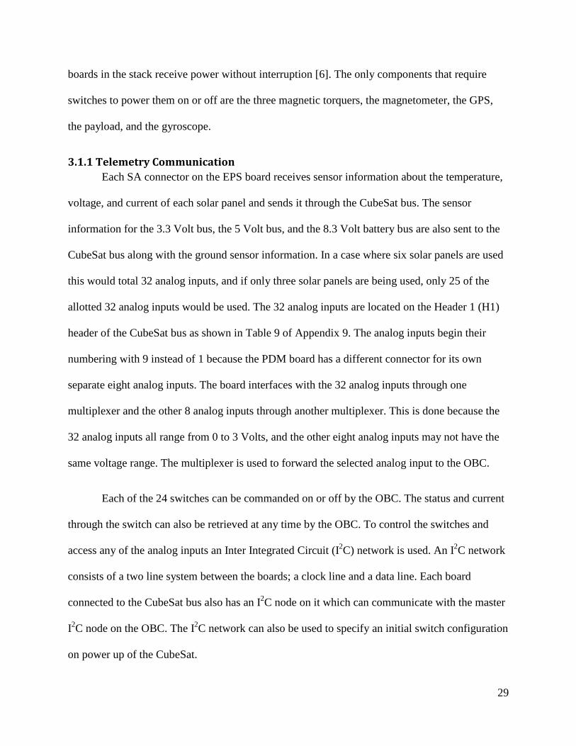
3.1.1 Telemetry Communication Each SA connector on the EPS board receives sensor information about the temperature,
voltage, and current of each solar panel and sends it through the CubeSat bus. The sensor
information for the 3.3 Volt bus, the 5 Volt bus, and the 8.3 Volt battery bus are also sent to the
CubeSat bus along with the ground sensor information. In a case where six solar panels are used
this would total 32 analog inputs, and if only three solar panels are being used, only 25 of the
allotted 32 analog inputs would be used. The 32 analog inputs are located on the Header 1 (H1)
header of the CubeSat bus as shown in Table 9 of Appendix 9. The analog inputs begin their
numbering with 9 instead of 1 because the PDM board has a different connector for its own
separate eight analog inputs. The board interfaces with the 32 analog inputs through one
multiplexer and the other 8 analog inputs through another multiplexer. This is done because the
32 analog inputs all range from 0 to 3 Volts, and the other eight analog inputs may not have the
same voltage range. The multiplexer is used to forward the selected analog input to the OBC.
Each of the 24 switches can be commanded on or off by the OBC. The status and current
through the switch can also be retrieved at any time by the OBC. To control the switches and
access any of the analog inputs an Inter Integrated Circuit (I2C) network is used. An I2C network
consists of a two line system between the boards; a clock line and a data line. Each board
connected to the CubeSat bus also has an I2C node on it which can communicate with the master
I2C node on the OBC. The I2C network can also be used to specify an initial switch configuration
on power up of the CubeSat.

30
The PDM Board is also capable of connecting to five serial-based devices. The Serial
interfaces are designed to act as bridges or buffers between serial based devices and the I2C
network. The components of the CubeSat that would connect to the PDM through a serial
interface are the magnetometer, the GPS and the payload.
3.1.2 EPS Switch Configuration The EPS Board has connection points that connect to the two separation switches and the
pull pin. When the pull pin is inserted in the CubeSat or either of the deployment switches is
actuated all power to the CubeSat is stopped. A possible connection between the CubeSat bus’s
second header pins and the deployment switches and the pull pin is shown in Figure 12 below.
The dummy load prevents damage to the BCR when the solar arrays are attached and the battery
is not connected. This feature is not a requirement and is only intended as a suggested protection
while the pull pin is connected.
Figure 12: Possible Configuration of Pull Pin and Separation Switches (adapted from [6])

31
3.2 Telecommunication Subsystem
3.2.1 Implementation of Telecommunication Subsystem Hardware
For the proposed mission, a strong emphasis will be put on transferring data collected by
the onboard instrument back to ground stations. This requires a telecommunication system
structured around multiple robust, efficient connections with high data transfers. To meet these
requirements, hardware designed for CubeSat communication has been selected to maximize
transmitter output and datarates. This selection will set the baseline for selecting ground stations
to maximize access and in turn the total data that can be transferred.
UHF Primary Downlink and VHF Uplink
The ISIS TRXUV UHF (400-450MHz)/VHF (130-160MHz) Transceiver has been
selected for the primary radio for its reliability and full-duplex (simultaneous transmit and
receive) capability. It is a well rounded platform offering reasonably high data rates of 9600bits/s
in a CubeSat specific package designed to work seamlessly with the other components. It fulfills
all the requirements of a CubeSat transceiver, accomodating telemetry downlink, tracking, and
command uplink.
Modulation is handled by Binary Phase Shift Keying (BPSK), Frequency Shift Keying
(FSK), Audio Frequency Shift Keying (AFSK), or Manchester FSK as specified by the user.
These are simple modulation schemes centered around either phase or frequency shifting to carry
data; in this case a series of binary bits. While there are more powerful modulation techniques to
expand bandwidth or raise efficiency compared to these simple modulations schemes, the
simplicity of the proposed system makes implementation straightforward and makes the system
more robust and flexible.

32
The antenna options for cubesats are limited due to space requirements. Generally
CubeSats use one of four configurations: monopole, dipole, turnstile, and patch antennas. The
antenna system best suited to the mission is the ISIS deployable UHF/VHF antenna system. This
allows the use of one of three configurations: four monopole antennas, two dipole antennas, or
one turnstile. For this mission, the dipole configuration was chosen because of its ability to run
both a UHF transmitter and a VHF receiver from the same unit providing a compact solution.
Along with the semi-omnidirectional profile of the dipoles, which will limit the pointing losses
regardless of orientation, this antenna offers a comprehensive solution to the antenna choice for
the CubeSat.
S-Band Secondary Downlink
To further increase the downlink data rate, a secondary radio operating on the 2.4 GHz S-
band is being considered. The Clyde Space STX5 is a transmitter designed specifically for this
purpose on CubeSats and could significantly enhance the transmission capabilities of the
CubeSat. The S-band allows for data rates up to 2 Mbps6, however it comes at the price of
reliability, power, and cost. There are also fewer ground station options for S-band CubeSats,
although the band is widely used on larger commercial satellites.
Modulation is handled by QPSK (Quadrature Phase Shift Keying), which is partly
responsible for the high data rate. QPSK uses four phases of modulation, as opposed to two for
BPSK, so it can handle twice the data for the same bandwidth and Bit Error Rate(BER). The
downside is the complexity of QPSK and the higher power needed.
5 STX: S-Band Transmitter from ClydeSpace 6 Mbps: Mega Bytes per Second

33
Antenna options for S-band are primarily limited to patch antennas due to the higher
power required for equivalent bandwidth compared to UHF or VHF. Although patch antennas
are simpler and easier to implement than deployable dipoles or similar, they are highly
directional, producing a beamwidth of approximately 65o with significant losses outside of this
range. This proves problematic for this mission proposal since the pointing requirements for the
Cubesat are sun dependent and there is no primarily nadir (Earth facing) side to mount the
antenna. A possible solution is the use of ground stations near the equator where the –Z side of
the satellite would be within the pointing requirements.
3.2.2 Ground Station Network
Ground tracks are the projected path of a satellite’s orbit on the surface of the Earth,
which traces the movement of an imaginary line between the satellite and the center of the Earth.
Also it is considered a set of points that the satellite will pass directly over in the frame of
reference of a ground observer [16]. There are a few parameters that can cause variations in the
ground tracks, such as orbital period and orbital inclination. A satellite with an orbital period of
an integer fraction of a day (24 hours, 12 hours, 8 hours, etc.) will for the most part follow the
same path day to day. The ground tracks will be shifted east or west depending on the longitude
of the ascending node, which vary over time due to perturbations of the orbit. If the period is
slightly larger than an integer fraction of a day the ground track will shift west over time and will
shift east if it’s slightly shorter. Orbital inclination is the angle formed between the plane of an
orbit and the equatorial plane of the Earth. The orbital inclination, i, will range from –i to i for
the geographic latitudes covered by the ground track. The larger the inclination then the further
north and south the satellite’s ground track will pass. An inclination of exactly 90o is said to be in
a polar orbit, it passes over the Earth’s north and south poles.
34
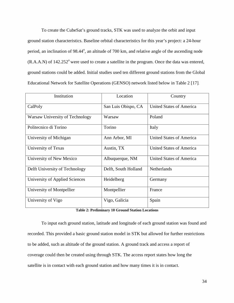
To create the CubeSat’s ground tracks, STK was used to analyze the orbit and input
ground station characteristics. Baseline orbital characteristics for this year’s project: a 24-hour
period, an inclination of 98.44o, an altitude of 700 km, and relative angle of the ascending node
(R.A.A.N) of 142.252o were used to create a satellite in the program. Once the data was entered,
ground stations could be added. Initial studies used ten different ground stations from the Global
Educational Network for Satellite Operations (GENSO) network listed below in Table 2 [17].
Institution Location Country
CalPoly San Luis Obispo, CA United States of America
Warsaw University of Technology Warsaw Poland
Politecnico di Torino Torino Italy
University of Michigan Ann Arbor, MI United States of America
University of Texas Austin, TX United States of America
University of New Mexico Albuquerque, NM United States of America
Delft University of Technology Delft, South Holland Netherlands
University of Applied Sciences Heidelberg Germany
University of Montpellier Montpellier France
University of Vigo Vigo, Galicia Spain
Table 2: Preliminary 10 Ground Station Locations
To input each ground station, latitude and longitude of each ground station was found and
recorded. This provided a basic ground station model in STK but allowed for further restrictions
to be added, such as altitude of the ground station. A ground track and access a report of
coverage could then be created using through STK. The access report states how long the
satellite is in contact with each ground station and how many times it is in contact.

35
Figure 13: Ground track with ground stations

36
Figure 14: Access Report
Figure 13 is a screen shot of the ground tracks over the ground stations. The thin, light
blue line is the ground track that the satellite is on. The thicker, different colored lines are the
portion of the ground tracks during times the satellite is in contract with a ground station. The
different colors correspond with the different ground stations. Figure 14 is a screen shot of the
access report that STK compiles from the information on the satellite orbit and the ground
stations. From this information ground stations were streamlined to only focus on how much data
could be transmitted. The final choices are listed below in Table 3.

37
Institution Location Country
Nicolaus Copernicus Astronomical Center
Warsaw University of Technology
Warsaw, Poland
Delft Command Ground Station (DCGS)
Delft University of Technology
Delft, Netherlands
FASTRAC University of Texas at Austin Austin, Texas Cal Poly Earth Station – N6CP
California Polytechnic State University
San Luis Obispo, California
Table 3: Final Ground Station Locations
The appropriate antenna information was added to each ground station and a second
access report and link report was run. From the link report shown in Figure 15, the amount of
data that will be transmitted during the 24 hour period is given.
Figure 15: Link Budget

38
Figure 16: Access Report for the Four selected Ground Stations
As the access report in Figure 16 shows, the total data in a 24 hour period is 98 Mb. To
increase the possible amount of data transmitted, more research on adding more ground stations
to expand the coverage of the satellite will have to be done. Figure 16also shows the most the
satellite will pass over any given ground station is six times every fifteen orbits. Ground stations
in the area of Asia or at least further away from other ground stations will need to be researched
since there is significant overlap between current ground stations being used.

39
3.2.3 STK Analysis
A critical step in design of a telecommunications system is modelling of the links through
STK an AGI (Analytical Graphics Inc.) software suite designed to model various satellite
systems and missions. This project made use of various communications tools within STK.
Scenario
STK allows users to define orbital and mission based parameters to simulate various
systems and scenarios. Various orbits can be simulated to understand the direct effects of orbital
characteristics on the system. Objects such as satellites, ground stations, targets, and celestial
bodies can be added to the model and constrained to the mission specifications. The satellite
capabilities can be constrained through specification of transmitters, receivers, and antennas to
map the various links. Ground stations are indicated on the earth map with the analysis using the
transmitters, receivers, and antennas specified by the user for each of the sites.
Figure 17 below shows the ground tracks of the CubeSat and locations of the four chosen ground
stations in Warsaw, Delft, Cal Poly, and University of Texas. The access to these stations is
highlighted and color-coded to the specific stations.
Figure 17: Ground tracks of the CubeSat plotted using STK.

40
Limits and Constraints
The satellite itself is constrained by the orbital parameters, which are the baseline orbital
characteristics for this year’s project: a 24-hour period, an inclination of 98.44o, an altitude of
700 km, and R.A.A.N of 142.252o. Optimally, a sun sychronous repeating trace orbit would be
used, but this is beyond control.
The satellite is assumed to have a transmitter operating in the UHF band with the
following characteristics:
• Frequency : 435.5 MHz • Power: 0 dBW (1 Watt) • Data Rate: 9.6 Kb/s • Modulation: FSK • Pointing loss: -1 dB
The assumed antenna on the CubeSat is designed for the UHF band with the following
characteristics.
• Dipole • Length: 0.55 m • Length/Wave Length: 0.799 • Efficiency: 55% • Refraction Model: ITU-R P.834-4 7 • Range limit: 3000 km.
Each of the ground stations incorporated a medium complexity receiver model with the
following constraints:
• Gain 32.8 dB • Line Loss: 4dB • Antenna noise from sun, atmosphere, rain computed by STK • LNA (low noise amplifier) noise figure 1.2 dB • Refraction Model: ITU-R P.834-4 • Min Elevation angle 5 deg. • Doppler Shift: +/- 25 kHz
7 ITU-R P.834-4: Effects of tropospheric refraction on radiowave propagation. International Telecommunications Union. [67]

41
Reports
From the aforementioned modeling constraints, STK can calculate the maximum access
and link conditions for the model. This data is recorded within STK and can be exported in a
number of report formats. The reports providing the needed information to accurately assess the
telecommunication system capability.
The Access Reports consist of the duration and occurance of links between the satellite
transmitter and ground station receivers. This is affected by the orbital parameters and the field-
of-view of the satellite and ground station, especially the effective range of the transmitter and
the minimum elevation of the field-of-view from the ground station. Figure 18 shows the
CubeSat within range of the Delft and Warsaw ground stations. STK calculates the coverage for
both, although when considering the amount of data received, it should be noted that data will be
redundant when two ground stations are connected to the Cubesat simultaneously. However, this
does have the benefit of being able to check the stream of data using two or more sources for
increased accuracy.
Figure 18: Ground track showing location of satellite connected to two ground stations (Delft and Warsaw).
42
Figure 15 is the access report data from a 24 hour period. In this time the CubeSat would
make approximately 15 orbits around the earth, clearly demonstrating that there is marked room
for improvement in coverage.
The link budget supplies vital data of the various link characteristics such as EIRP
(Effective Isotropically Radiated Power), RIP (Received Isotropic Power) and BER. The values
are calculated by STK and can be analyzed to determine further constraints in the simulation and
specify the proper components. The output values can be seen in Figure 16.
3.3 Thermal Subsystem
3.3.1 Thermal Analysis from External Sources
CubeSat Attitude Determination and Control MQP Team 2011-2012 [18]used STK to
find spacecraft-sun vectors for multiple orbits. The spacecraft-sun vector is coordinates of the
satellite from its location to the sun. These values were converted to beta values where the
magnitude of the vectors equal 1. Once the time-dependent beta values were found, the next task
was to import them into COMSOL to begin the next step in the thermal analysis. With these
values the solar flux can be made time dependent. Since the position of the CubeSat is changing
over the course of its orbit, the solar flux will vary with time. The Mechanical, Power, and
Thermal CubeSat Team 2011-2012 defined the magnitude of the solar flux during its orbit by
using a rectangle function [1]. This function is set with a one variable expression with a lower
limit and an upper limit. The team set these limits to 0 to represent no sun and 1 for full exposure
to sunlight. The rectangular function was then imputed into an analytic function where it was
periodically repeated for the time of two orbits. However, the group did not take into account the
position of the satellite with respect to the sun. That is why the beta values are essential for the

43
thermal analysis. It will produce more accurate results in order to create a better thermal
management plan.
To import the spacecraft-sun vectors, an interpolation function was used, as defined
under Global Definitions in COMSOL. An interpolation function can fill in a table or be
imported as .csv or .txt files. A defined interpolation function contains values of 𝑡 and 𝑓(𝑡). For
this model, the 𝑡 represents the time in orbit and 𝑓(𝑡) represents the beta values. A .csv file was
imported for each component of beta. Beta will change over time since the position of the
satellite is changing throughout its orbit. With the beta values defined, an equation was created
for a time dependent solar flux. The solar flux is defined as:
𝑞𝑠𝑢𝑛 = 1367 𝑊𝑚2 𝑛�⃑ = �
𝑛𝑥𝑛𝑦𝑛𝑧� 𝛽 = �
𝛽𝑥𝛽𝑦𝛽𝑧�
𝑸 = 𝒒𝒔𝒖𝒏(𝒏��⃑ ∙ 𝜷��⃑ ) Equation 1
The average flux from the sun is 𝑞𝑠𝑢𝑛 and 𝑛�⃑ is the unit normal vector of each face of the
CubeSat. Q is the total solar flux on the CubeSat. Some preliminary analysis was needed to
ensure Equation 1 worked. First, it was tested on an arbitrary Two-Dimensional (2D) surface of
dimensions 10cm by 10cm in order to see the effects of solar flux over time on the surfaces.
Once the results from the 2D analysis concluded that COMSOL can solve the solar flux
equation, a Three-Dimensional (3D) cube of dimensions 10cm by 10cm by 10cm was modeled.
As shown in Figure 19, there is a significant difference in temperature from the initial to final
time step, 0 to 172800 seconds. With the preliminary analysis complete, the analysis was
implemented onto the final version of the CubeSat Model.
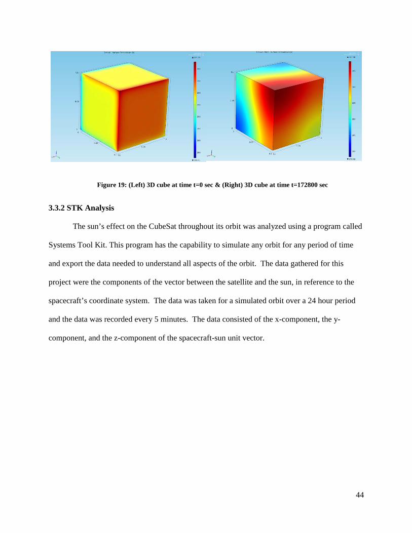
44
Figure 19: (Left) 3D cube at time t=0 sec & (Right) 3D cube at time t=172800 sec
3.3.2 STK Analysis
The sun’s effect on the CubeSat throughout its orbit was analyzed using a program called
Systems Tool Kit. This program has the capability to simulate any orbit for any period of time
and export the data needed to understand all aspects of the orbit. The data gathered for this
project were the components of the vector between the satellite and the sun, in reference to the
spacecraft’s coordinate system. The data was taken for a simulated orbit over a 24 hour period
and the data was recorded every 5 minutes. The data consisted of the x-component, the y-
component, and the z-component of the spacecraft-sun unit vector.
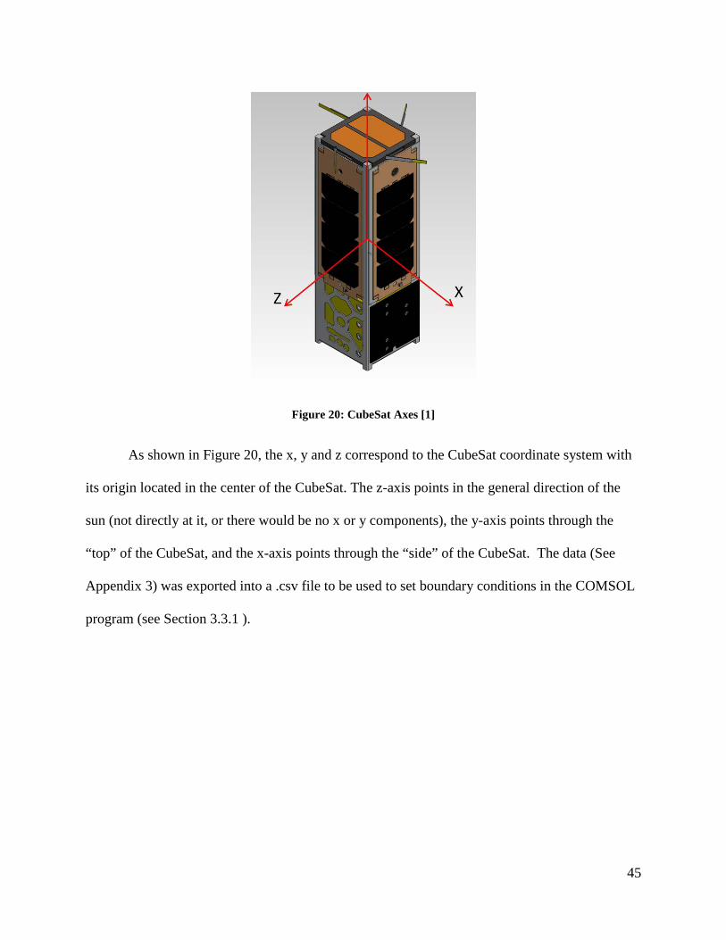
45
Figure 20: CubeSat Axes [1]
As shown in Figure 20, the x, y and z correspond to the CubeSat coordinate system with
its origin located in the center of the CubeSat. The z-axis points in the general direction of the
sun (not directly at it, or there would be no x or y components), the y-axis points through the
“top” of the CubeSat, and the x-axis points through the “side” of the CubeSat. The data (See
Appendix 3) was exported into a .csv file to be used to set boundary conditions in the COMSOL
program (see Section 3.3.1 ).

46
Figure 21: CubeSat-Sun Vector
Figure 21 shows the simulated orbit and the vector from the CubeSat pointing to the sun
(which changes its angle over time). It can be seen here that the orbit path goes behind the earth
on multiple occasions. However the recorded data does not indicate when the CubeSat is behind
the Earth or when it is in direct sunlight. These periods of occultation need to be independently
identified by the user because it will affect the fluctuation of the thermal profile.
3.3.3 Vacuum Modeling in COMSOL
One of the thermal P-POD requirements states that a CubeSat must undergo a Thermal
Vacuum Bakeout test before it is integrated into the P-POD. The Mechanical, Power, and
Thermal CubeSat MQP 2011-2012 team began a lab option to perform a vacuum test using the
vacuum chamber located in the basement of Higgins Laboratories on the WPI campus [1]. For
analysis and testing, they chose the simple aluminum structure that the Mechanical and

47
Structural Subgroup built which is shown in Figure 22. They believed that using this structure
would be much easier to perform thermal analyses and form meshes during COMSOL analyses.
Using what was suggested for future groups, a model was created to be simulated in COMSOL.
Figure 22: Aluminum Skeleton for Lab Option (2012) [1]
Before creating a model for analysis, a layout had to be developed for the Lab Option. In
the chamber, the CubeSat skeleton would be suspended from the aluminum stand, created by the
Mechanical and Structural Subsystem. The stand and the skeleton would be positioned in front of
the cryopump. A halogen lamp will simulate the heat flux from the sun and be positioned on the
other side of the cryopump.
In choosing which heat transfer module to use, the best option was “Heat Transfer with
Surface-to-Surface Radiation.” Two other options had “Radiation in Participating Media” which
implies that there is air or fluid in the system. When the cryopump pumps air out of the chamber,

48
it reaches temperatures close to absolute zero and pressures below 50 mTorrs. Based on this
knowledge, the ambient temperature inside the chamber was set to 30 degrees Kelvin.
During testing, five thermocouples measure the temperature at arbitrary points on the
aluminum CubeSat skeleton. Since the size and weight of the thermocouples are relatively small
in comparison to the other geometries, there is no need to model them in COMSOL. A 1-D plot
group was chosen to view the temperature readings from the thermocouples. In this setting,
edges or points of the skeleton are selected to view the temperature range for each time interval.
These plots allow for comparison of results from the analysis to the lab option test.
3.3.4 Lab Option in Vacuum Chamber
To validate the COMSOL thermal model of the CubeSat structure, an experiment in a
vacuum chamber was prepared. All materials were purchased so but there was not enough time
to run the experiment.
Material Manufacturer Part Number Halogen Lamp and Bulb Workforce 778-980 Aluminum Sheet MSC Industrial Supply Co. 09426057 PCB Mouser Electronics 590-588 Thermocouples Omega 5SRTC-GG-(K)-24-(36) Thermocouple extension wires McMaster-Carr 3870K32 Connectors for the thermocouples to the chamber feedthroughs
McMaster-Carr 3869K48
Chamber electrical feedthrough Kurt J. Lesker Co. EFT0042031 Table 4: Lab Option Materials Purchased
Additional information on each item listed in Table 4 can be found in Appendix 4. The
LabView file that will be used to collect and analyze the data was developed by the CubeSat
MQP 2011-2012 team that first provided suggestions for a vacuum chamber experiment [1].

49
The experimental procedure involves three major steps as follows. Prior to actual testing,
a detailed procedure will need to be prepared for each of these.
1. Mount lamp and CubeSat model so that they are thermally isolated from the chamber walls using monofilament (fishing) line.
2. Place thermocouples in selected locations to measure the thermal profile of the CubeSat. 3. Run vacuum chamber with lamp on and take data both from the sides exposed to the light
and not exposed to the light.
The results of this experiment can be compared to the results of the COMSOL simulation
of the same situation.
3.3.5 Thermal Control System
The thermal control system ensures that the operational temperatures of each component
are not exceeded. The following table shows the operating temperatures for the equipment on
board. The data has been collected from the specifications given by the manufacturers.
Component Operational Temp (°C) Reference OBC -40 85 [19]
ADC board No Data [20] Course Sun Sensor (3
or 5) -40 100 [21] Fine Sun Sensor -25 50 [9]
Gyro -40 105 [22] Magnetic Torquers (3) No Data [23]
Magnetometer -30 85 [24] GPS 0 50 [25]
SphinX NG Instrument Self-regulating thermal abilities - EPS Board -40 85 [6] PDM Board -40 85 [7]
Battery -10 50 [26] Front Solar Panels -40 80 [27] Side Solar Panels -40 80 [28] UHF Transceiver -30 70 [10]
Table 5: Operational Temperatures

50
From Table 5, it is evident that certain components have more limited ranges of operable
temperatures and the minimum temperature at which the entire system can function is 0 °C and
the maximum is at 50 °C. Since the temperature in space can range from -100 °C to 120 °C [29]
this limited range of operational temperatures means that the use of heaters may be necessary.
There will also need to be insulation to prevent overheating while in direct sunlight.

51
4 Results
4.1 Power Subsystem
4.1.1 Power Subsystem Hardware, Monetary and Power Budget
As the details of the project changed, the previously discussed power budget was
updated. As hardware became finalized, power consumption values were established. Table 6
lists the different hardware items and their respective average power consumption values at the
time this report was completed. The table was created in order to ensure that margins of power
will always cover the entire system at any point. Each phase of the orbit will require different
amounts of power supply from each piece of hardware. The solar power supply however, will
fluctuate over the course of the CubeSat’s orbit, as the spacecraft goes into and out of eclipse.
During sunlight periods, the solar panels will re-charge the battery for use during the periods of
time in eclipse. With Table 6 establishing power by mission phase was simple to budget.

52
Table 6: Updated Power Budget
Group Component Company Part Number Peak
Power (W)
Nominal Power
(W)
Quiescent Power
(W)
Current (mA)
Voltage (V)
OBC OBC Tyvak Intrepid 0.300 0.30 0.20
ADC
ADC board Clyde-Space CS-ADCS-INT-01 0.100 0.10 0.10
Course Sun Sensor (5)
ComTech AeroAstro
CubeSat Sun Sensor 0.000 0.00 0.00 <5 3.3/5
Fine Sun Sensor
SSBV Space and Ground
Systems Fine Sun Sensor 0.140 0.14 0.14 7.5(26) 3.3 /
5(5-50)
Gyro Surrey ADXRS450 0.030 0.03 0.03 6.0 3.15 - 5.25
Magnetic Torquers (3)
Zarm Technik AG
MTO 5.1 (Optimized) 0.275 0.275 0.14 55.0 5
Magnetometer Honeywell HMC5883L 0.000 0.000 0.00 0.100 2.16-3.6
GPS
Surrey Satellite
Technology US LLC
SGR-05U 0.800 0.80 0.80 16.0 5
Payload Instrument Sphinx NG - XRAY 8.000 8.00 1.00 TBD TBD
Power
EPS Board Clyde-Space CS-3UEPS2-NB 0.100 < 0.1 < 0.1
over current
protection
3.3/5/ raw
battery
PDM Board Clyde-Space CN-SWT-0035-CS 0.160 0.16 0.16
24 switches
each with own current
telemetry
3.3/5/12/ battery
Battery Clyde-Space CS-SBAT2-30 1.25 Ah 8.2 Front Solar
Panels Clyde-Space SP-L-F2U-0033-CS 5.200 3.35 0 12.26-
7.52 Side Solar
Panels Clyde-Space SP-L-S2U-0031-CS 15.600 6.70 0.00 12.26-
7.53
Telecom UHF Transceiver ISIS Transceiver and
Antenna 2.100 0.20 0.00 TBD 6.5-12.5
Total 12.005 9.705 2.370
Total Available 50.800 40.050 30.000
Margin 38.795 30.345 27.630

53
According to established CubeSat requirements, all power must be off for launch. Once
launched and ejected from the launch vehicle, the battery must power everything until de-
tumbling is complete and the solar panels have been deployed to begin providing power. For this
period, the battery will provide up to 2.4 hours of power to supply the entire CubeSat even in the
event that all hardware were to be on at the same time [2].
The CubeSat hardware must also be completely enclosed in the skeleton. With all of
these requirements, a method of charging the battery must be established. A Universal Serial Bus
(USB) cord and an adapter that can be plugged into the PDM board will allow the battery to be
charged to a full 30 Watt-Hours in order to begin the de-tumble sequence and to deploy the main
power source consisting of the solar panels.
The specifications for the hardware chosen and discussed have been reviewed to insure
that the CubeSat can work efficiently. The final hardware choices are shown above in the power
budget in Table 6. A cost estimate for the hardware can be seen in Table 7.
Component Part Number each number cost EPS Board CS-3UEPS2-NB $ 4,500.001 1 $ 4,500.00 [6] PDM Board CN-SWT-0035-CS $ 7,750.001 1 $ 7,750.00 [7]
Battery CS-SBAT2-30 $ 3,550.001 1 $ 3,550.00 [26] Front Solar Panels SP-L-F2U-0033-CS $ 4,000.001 1 $ 4,000.00 [27] Side Solar Panels SP-L-S2U-0031-CS $ 4,150.001 2 $ 8,300.00 [28]
Total $ 28,100.00
Table 7: Power Hardware Costs
All power hardware chosen for the CubeSat is manufactured by the same company,
Clyde Space. The choice to use only one company for all parts of this subsystem almost
guarantees that the component boards will communicate well between each other.

54
4.1.2 Wiring Results
The CubeSat bus will connect the transceiver, ADC, battery, EPS and PDM boards
together with the possible exception of the OBC as indicated in Figure 34 of Appendix 8. The
location and type of the OBC interfaces are as yet unspecified and need to be determined. As a
result, ribbon cable will probably be needed to connect the board stack and the OBC. The
CubeSat bus has two 52 pin headers which are as labeled in Figure 35 of Appendix 8. The
purpose and connections of each of the pins of the CubeSat bus are also listed in Table 9 and
Table 10 of Appendix 9. The devices that connect to the board stack can then be divided into
three groups. The first group consists of devices that use power and relay information to the
OBC. The second group relays information to the ADC board directly and receives power from
the PDM board with the exception of the four Coarse Sun Sensors. The third group consists of
the magnetic torquers which are actively powered, but do not relay any information to the board
stack. The wire connections to the magnetic torquers via the CubeSat bus are listed in Table 11
of Appendix 9.
The devices in the first group consist of the solar arrays and the Sphinx instrument. Each
of the three solar arrays has three connecting wires as labeled in Figure 36 of Appendix 8. The
solar array wires are connected to the EPS board through the SA connectors labeled in Figure 37
of Appendix 8 and the pin numbering of the SA connectors is as labeled in Figure 38 of
Appendix 8. The connections of the solar array wires to the connector pins are listed in Table 11
of Appendix 9. The payload wiring consists of a wire that will provide power through the PDM
board, a ground wire and a wiring harness that will relay information to the OBC directly. The
connectors for the Sphinx and OBC are unknown at the present time, so the design of the wiring
harness to connect them should be a goal of future work. The power and ground wire

55
connections to the payload instrument are listed in Table 10 of Appendix 9. Although the
connectors to the OBC are unknown, the connection types can be found in Appendix 10. The
devices in the second group consist of the gyroscope, the magnetometer, the four Coarse Sun
Sensors, the CubeSat Sun Sensor, and the GPS. The devices listed should connect directly to the
ADC board from Clyde Space. According to one of their representatives the ADC board can be
built to suit the interface needs of each of the devices. The wires and wire connection points for
the gyroscope, magnetometer, coarse sun sensor, and GPS are labeled in Figure 39, Figure 40,
Figure 41 and Figure 42 of Appendix 8. The location of the CubeSat sun sensor’s wire
connection points are unknown and will have to be identified in future work. However it is
known that the CubeSat sun sensor has four analog wires which will provide information to the
ADC board, aside from the power and ground wires [30]. The connection of the devices to the
ADC board and the CubeSat bus are as indicated in Table 11 of Appendix 9.
4.2 Telecommunication Subsystem
4.2.1 Mission Modeling and Timelines
The STK model allows for precise estimations of both ground station access and link
budgets as described in the methodology. The data from these reports was imported into Excel
files and organized by simulated mission date range and ground station. The plots in Figures 25-
27 were created from this data.

56
Figure 23: Total expected daily access time as a function of launch date.
Figure 23 shows the access time that can be expected over all 5 selected ground stations
for both the uplink and downlink. The data in the figure was generated using data from various
simulations, with different launch dates, in STK. The propagation of the CubeSat’s orbit is the
main determining factor in access time achieved, while weather and other atmospheric effects
contribute to varying path losses. It was expected that the uplink access would be higher than the
downlink access (in simulations, about 20% on average for downlink) due mainly to the
increased transmission power achievable at the ground stations compared to the CubeSat
transmitter. Another factor is the increased distance achievable with VHF compared to UHF at a
given power level. Overall, a mean access of 10609.7 seconds for the downlink and a mean
access of 12076.1 seconds for the uplink can be expected over a 24 hour period. Figure 24and
Figure 25 show the access discussed above divided among the various ground stations.
8000
8500
9000
9500
10000
10500
11000
11500
12000
12500
13000
Nov Dec Jan Feb Mar Apr May Jun Jul
Acce
ss ti
me
per 2
4 Ho
ur P
erio
d (s
econ
ds)
Time of Year (2012-13)
Uplink
Downlink

57
Figure 24: Expected daily downlink access at each ground station as a function of launch date.
Figure 25: Expected daily uplink access at each ground station as a function of launch date.
From the plots, there is a preference towards use of the European ground stations in order
to maximize total access time. This is in part due to the choice of orbit when modeling and may
0
500
1000
1500
2000
2500
3000
3500
Nov Dec Jan Feb Mar Apr May Jun Jul
Acce
ss ti
me
per 2
4 Ho
ur P
erio
d (s
econ
ds)
Time of Year (2012-13)
Calpoly
Delft
University of Texas
Warsaw
WorcesterPolytechnic Institute
0
500
1000
1500
2000
2500
3000
Nov Dec Jan Feb Mar Apr May Jun Jul
Acce
ss ti
me
per 2
4 Ho
ur P
erio
d (s
econ
ds)
Time of Year (2012-13)
Calpoly
Delft
University of Texas
Warsaw
Worcester Polytechnic Institute
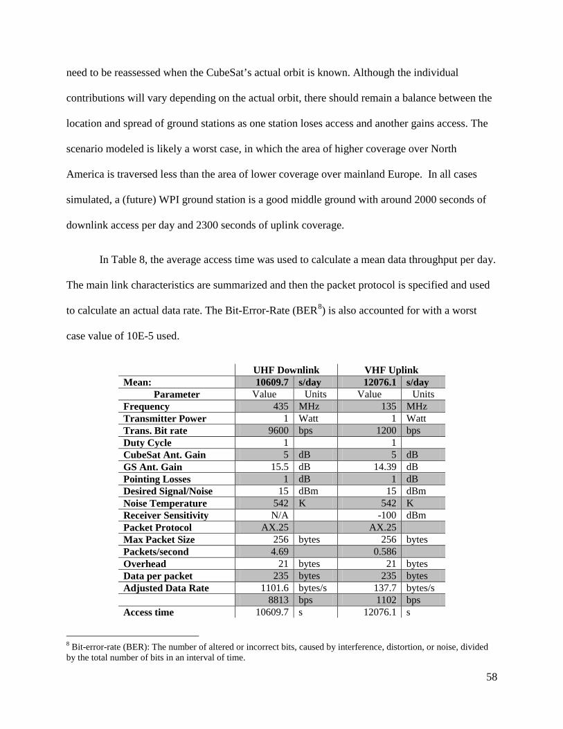
58
need to be reassessed when the CubeSat’s actual orbit is known. Although the individual
contributions will vary depending on the actual orbit, there should remain a balance between the
location and spread of ground stations as one station loses access and another gains access. The
scenario modeled is likely a worst case, in which the area of higher coverage over North
America is traversed less than the area of lower coverage over mainland Europe. In all cases
simulated, a (future) WPI ground station is a good middle ground with around 2000 seconds of
downlink access per day and 2300 seconds of uplink coverage.
In Table 8, the average access time was used to calculate a mean data throughput per day.
The main link characteristics are summarized and then the packet protocol is specified and used
to calculate an actual data rate. The Bit-Error-Rate (BER8) is also accounted for with a worst
case value of 10E-5 used.
UHF Downlink VHF Uplink Mean: 10609.7 s/day 12076.1 s/day
Parameter Value Units Value Units Frequency 435 MHz 135 MHz Transmitter Power 1 Watt 1 Watt Trans. Bit rate 9600 bps 1200 bps Duty Cycle 1 1 CubeSat Ant. Gain 5 dB 5 dB GS Ant. Gain 15.5 dB 14.39 dB Pointing Losses 1 dB 1 dB Desired Signal/Noise 15 dBm 15 dBm Noise Temperature 542 K 542 K Receiver Sensitivity N/A -100 dBm Packet Protocol AX.25 AX.25 Max Packet Size 256 bytes 256 bytes Packets/second 4.69 0.586 Overhead 21 bytes 21 bytes Data per packet 235 bytes 235 bytes Adjusted Data Rate 1101.6 bytes/s 137.7 bytes/s 8813 bps 1102 bps Access time 10609.7 s 12076.1 s
8 Bit-error-rate (BER): The number of altered or incorrect bits, caused by interference, distortion, or noise, divided by the total number of bits in an interval of time.
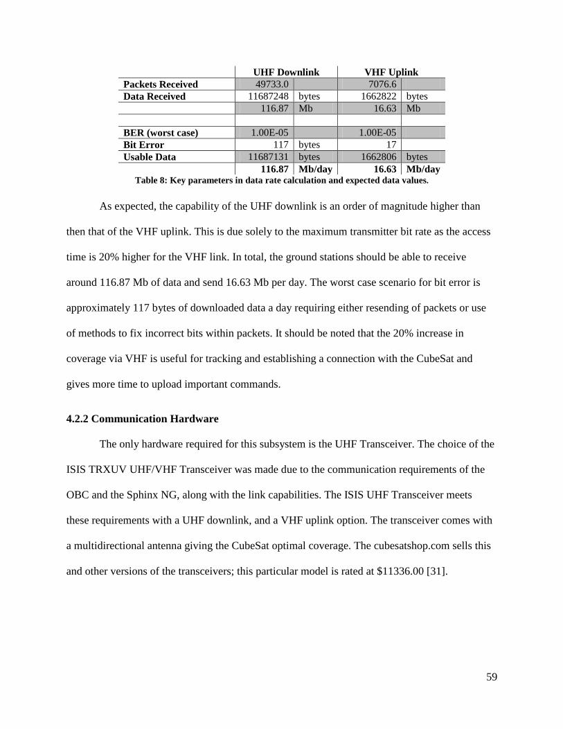
59
UHF Downlink VHF Uplink Packets Received 49733.0 7076.6 Data Received 11687248 bytes 1662822 bytes 116.87 Mb 16.63 Mb BER (worst case) 1.00E-05 1.00E-05 Bit Error 117 bytes 17 Usable Data 11687131 bytes 1662806 bytes 116.87 Mb/day 16.63 Mb/day
Table 8: Key parameters in data rate calculation and expected data values.
As expected, the capability of the UHF downlink is an order of magnitude higher than
then that of the VHF uplink. This is due solely to the maximum transmitter bit rate as the access
time is 20% higher for the VHF link. In total, the ground stations should be able to receive
around 116.87 Mb of data and send 16.63 Mb per day. The worst case scenario for bit error is
approximately 117 bytes of downloaded data a day requiring either resending of packets or use
of methods to fix incorrect bits within packets. It should be noted that the 20% increase in
coverage via VHF is useful for tracking and establishing a connection with the CubeSat and
gives more time to upload important commands.
4.2.2 Communication Hardware
The only hardware required for this subsystem is the UHF Transceiver. The choice of the
ISIS TRXUV UHF/VHF Transceiver was made due to the communication requirements of the
OBC and the Sphinx NG, along with the link capabilities. The ISIS UHF Transceiver meets
these requirements with a UHF downlink, and a VHF uplink option. The transceiver comes with
a multidirectional antenna giving the CubeSat optimal coverage. The cubesatshop.com sells this
and other versions of the transceivers; this particular model is rated at $11336.00 [31].

60
4.3 Thermal Subsystem
4.3.1 COMSOL Analysis Results
When performing simulations, COMSOL solved for the temperature of the surrounding
chamber and the lamp structure. This was undesirable for the model since simulations would
take more time to solve for geometries that were not part of the CubeSat. COMSOL Support was
contacted to see if they could shed some enlightenment to help solve this issue. In their response,
they stated that if the walls of the inner chamber were approximated as far away surfaces, then
the CubeSat structure can be modeled without the vacuum chamber. Since the size of the
skeleton is comparable to the actual chamber, it had to be included in the analysis. Based on this
feedback, simulations were performed to see if adding the chamber to the model would have a
significant effect on the final calculated temperature.
For the purposes of the modeling, simple geometry was used. To reduce the simulation
time, the lamp and vacuum chamber were modeled as surfaces instead of solid shapes. However,
when applying boundary conditions, surfaces (that are not part of a “solid”) cannot be selected
for any of the heat transfer choices such as initial values and heat flux. Because of this, the
chamber was given a relatively thin thickness. To be consistent, the chamber was defined using
dimensions approximating the actual chamber used for testing. The chamber has a 24.625 inch
inner radius and a length of 70.5 inches. For simplicity, the CubeSat was modeled as a 10 by 10
by 30 centimeter rectangular prism. Figure 26 shows the final model for the vacuum chamber
simulation.
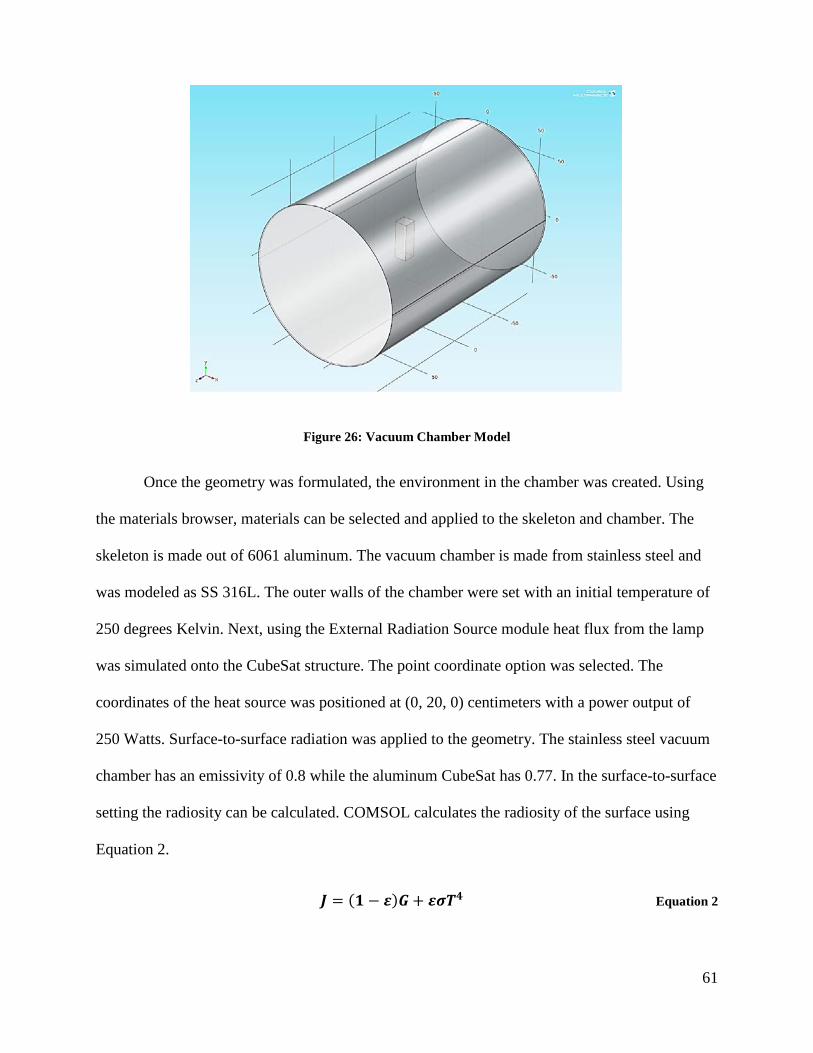
61
Figure 26: Vacuum Chamber Model
Once the geometry was formulated, the environment in the chamber was created. Using
the materials browser, materials can be selected and applied to the skeleton and chamber. The
skeleton is made out of 6061 aluminum. The vacuum chamber is made from stainless steel and
was modeled as SS 316L. The outer walls of the chamber were set with an initial temperature of
250 degrees Kelvin. Next, using the External Radiation Source module heat flux from the lamp
was simulated onto the CubeSat structure. The point coordinate option was selected. The
coordinates of the heat source was positioned at (0, 20, 0) centimeters with a power output of
250 Watts. Surface-to-surface radiation was applied to the geometry. The stainless steel vacuum
chamber has an emissivity of 0.8 while the aluminum CubeSat has 0.77. In the surface-to-surface
setting the radiosity can be calculated. COMSOL calculates the radiosity of the surface using
Equation 2.
𝑱 = (𝟏 − 𝜺)𝑮+ 𝜺𝝈𝑻𝟒 Equation 2

62
G is the unknown incident radiation, T is the initial temperature of the surface, 𝜎 is the
Stefan-Boltzmann constant (5.67 × 10⁻⁸ 𝐽𝑚2𝑠𝐾4
), and 𝜀 is the emissivity of a material. In the
Surface-to-Surface Radiation setting, T and 𝜀 are set as initial values. COMSOL calculates G
values from the geometric surfaces in the model.
After completing the simulation, results from the two studies were compared qualitatively
using two 1D plot groups. The first group graphed the temperature over the X, Y, and Z
coordinates of the CubeSat. Since the CubeSat is fixed at the origin and its dimensions are 10 by
10 by 30 centimeters, the coordinates for the X and Z directions were from -5 to 5 centimeters.
The coordinates in the Y direction is -15 to 15 centimeters. In Figure 27: Temperature vs.
Coordinate X, Y, Z, the dashed lines represent the study where the vacuum chamber is modeled,
and the solid lines are from the study where just the CubeSat was modeled. There is a significant
difference in temperature, about a 4 degree increase in temperature range. The second group
shows the radiosity over the coordinates of the CubeSat. Because the radiosity increased, the
temperature will also increase. Figure 28, Figure 29, and Figure 30 show the radiosity over the
X, Y, and Z coordinates of the CubeSat respectively.

63
Figure 27: Temperature vs. Coordinate X, Y, Z
Figure 28: Radiosity vs. Coordinate X

64
Figure 29: Radiosity vs. Coordinate Y
Figure 30: Radiosity vs. Coordinate Z

65
4.3.2 Thermal Analysis from External Sources
From the preliminary analysis in Section 3.3.1 , COMSOL can easily solve time
dependent solar flux equation. The next step was to take the solar flux equation and apply it to
the model of external components. COMSOL has the ability to import 3-D CAD assemblies to
create the geometry. With the help of the current Mechanical Subsystem MQP team, a simplified
structure of the CubeSat model in SolidWorks was created. The model contains the aluminum
structure from Pumpkin Inc., solar panels and hinges from ClydeSpace, and 1 millimeter thick
aluminum panels to protect the CubeSat.
Once the CAD file was imported, the material boundaries were applied to the
components. The Pumpkin structure and hinges are made of 7071 aluminum. After looking at the
ClydeSpace data sheet, the solar panels are actually made of multi-layered printed circuit board,
not solid copper as the Mechanical, Power, and Thermal CubeSat MQP 2011-2012 team
assumed [1].
To set up the solar flux equation, three interpolated functions were inserted, one for each
beta component. As explained in Section 3.3.1, an interpolated function contains values of 𝑡 and
𝑓(𝑡). Beta values were calculated from STK and then exported into an Excel file. The values
were extracted and three “.txt” files were created. In each file there were two columns. The first
column contained the time values from 0 to 172,800 seconds with an interval of 30 seconds. In
the second column was one component of beta corresponding to each time interval. The three
interpolation functions were renamed “Bx”, “By”, and “Bz.” Next, the solar flux and earth flux
constants were defined using the Global Parameters section in COMSOL. The constant solar flux
is 1367 𝑊𝑚2 and constant earth flux is 245𝑊
𝑚2.

66
Most of the boundary conditions that Mechanical, Power, and Thermal CubeSat MQP
2011-2012 team created were implemented in the model [1]. The heat flux was the major
change. When analyzing the CubeSat in a worst case scenario, multiple walls of the spacecraft
are subjected to the solar flux. If the CubeSat was oriented to have its solar panels facing the sun
at all times i.e. best case scenario, only the front face of the spacecraft would be subjected to the
solar flux. Equation 1 and the earth flux were used to formulate the total heat flux on the
CubeSat in orbit, shown in Equation 3.
𝒒𝒕𝒐𝒕 = 𝒒𝒆𝒂𝒓𝒕𝒉 + 𝒒𝒔𝒖𝒏[𝒏𝒙𝑩𝒙(𝒕) + 𝒏𝒚𝑩𝒚(𝒕) + 𝒏𝒙𝑩𝒛(𝒕)] Equation 3
In Equation 3, 𝑞𝑒𝑎𝑟𝑡ℎ is the constant earth flux and 𝑞𝑠𝑢𝑛 is the constant sun flux defined
in Global Parameters. Bx(t), By(t), and Bz(t) are the interpolated functions that are dependent on
time. The normal unit vectors nx, ny, and nz are for the X, Y, and Z faces of the CubeSat.
As for the remaining boundary conditions, surface-to-ambient radiation was applied to
each material. This setting defines the ambient temperature and surface emissivity.
According to several online references, the emissivity of a typical multilayer printed circuit
board was around 0.85. The emissivity of aluminum stayed the same at 0.77. Ambient
temperature represents an equivalent, blackbody temperature for the surroundings (the vacuum
of space) that the CubeSat is exposed to, or about 30 degrees Kelvin.
Meshing the simplified CubeSat structure was tedious. The main problem with imported
CAD files is the errors COMSOL generates when trying to apply the mesh. The option to use a
physics controlled mesh was not possible for most of the CubeSat structure. When “physics
controlled mesh” is selected, COMSOL automatically applies a mesh to components of the

67
model. There were many narrow edges that required sizing techniques. Figure 31 shows the final
mesh for the CubeSat.
Figure 31: Mesh for External Components
To analyze the temperature range during multiple orbits, the range of time was defined to
be from 0 to 10200 seconds with a 510 second interval (8.5 minutes). This interval was chosen to
minimize the calculation time without sacrificing the time resolution of the results. Because of its
fine mesh, choosing a smaller number for the time interval would result in the simulation taking
hours to run. After running the simulation, to see if there was a temperature trend over multiple
orbits, a line graph was created. All edges were selected and then plotted over time.
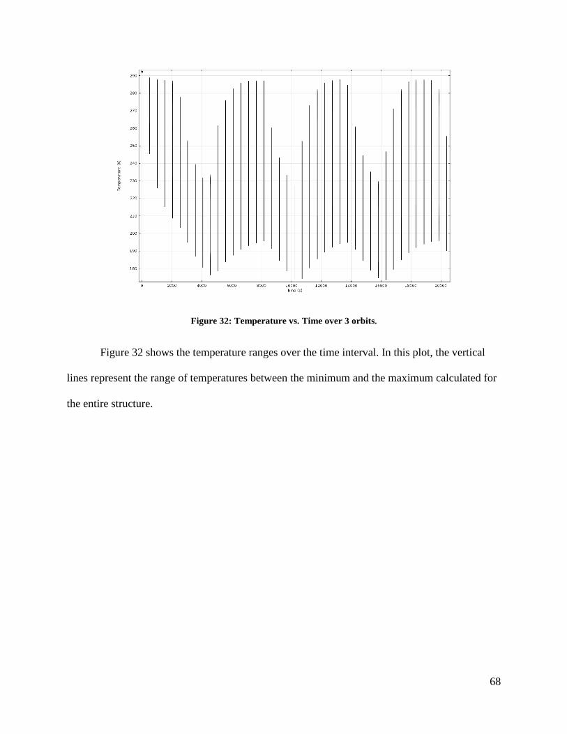
68
Figure 32: Temperature vs. Time over 3 orbits.
Figure 32 shows the temperature ranges over the time interval. In this plot, the vertical
lines represent the range of temperatures between the minimum and the maximum calculated for
the entire structure.

69
5 Conclusions and Recommendations
5.1 Power Subsystem
The next major step in the power subsystem is to establish a power timeline. This
timeline is established by the orbit, hardware use, ADC, and instrument use. As the CubeSat
goes in and out of eclipse, it will create a timeline for battery recharging and power supply. The
users’ power phases will then be established. Each phase will inform when and how much power
is necessary. Once the phases have been established, the OBC, transceiver, instrument, and ADC
timeline within each phase can be created. From these more detailed timelines, an on/off
sequence can be acquired. The power supply cycle will then need to be cross referenced with the
power user’s requirements to create a complete “On/Off” sequence to ensure sufficient power
will be received on time.
5.2 Telecommunication Subsystem
5.2.1 Hardware Testing Recommendations
Testing of the telecommunications system should be conducted when the hardware is
eventually obtained. The major focus of testing should be on verification of the manufacturer’s
specifications, comparison to link models, verification of link integrity, and verification of power
system compatibility [32]. This can be done through the use of link testing in an Radio
Frequency (RF) isolated chamber to limit any external RF interference with the test. The
transceiver should be connected to the ground station radio and terminal via a cable with known
loss and a variable signal attenuator. The signal attenuator is a device that acts as a RF power
dissipater, reducing the signal strength to incur a loss.
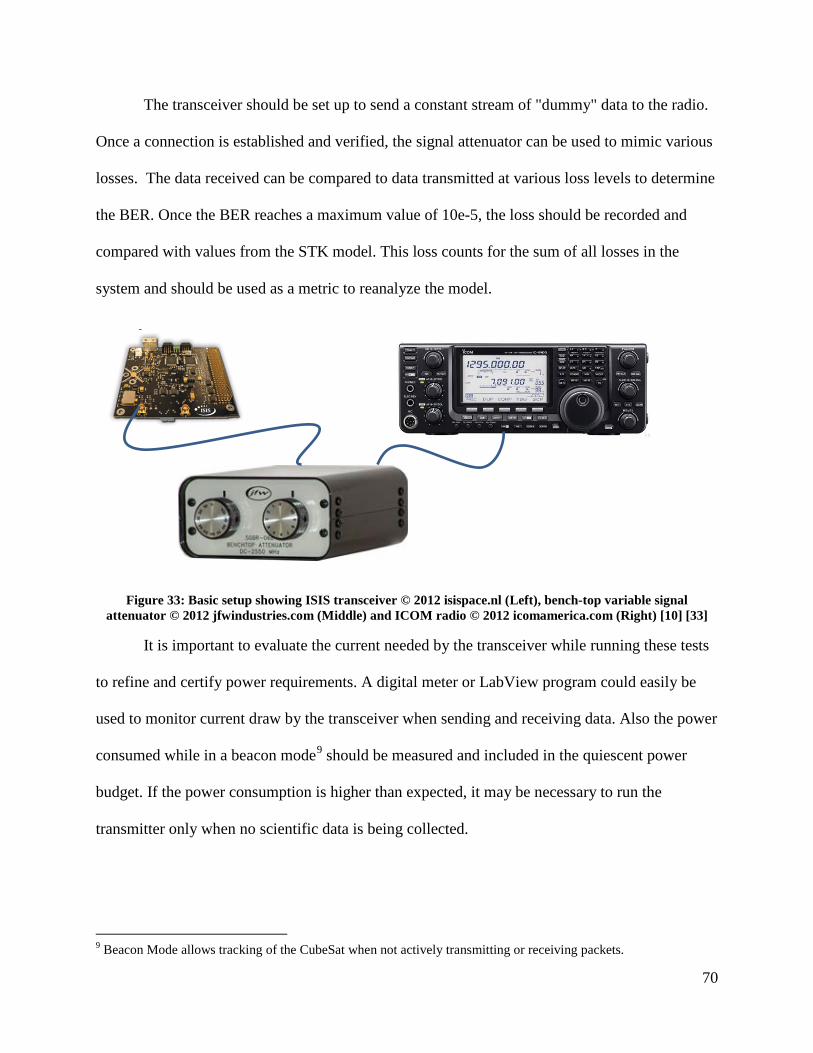
70
The transceiver should be set up to send a constant stream of "dummy" data to the radio.
Once a connection is established and verified, the signal attenuator can be used to mimic various
losses. The data received can be compared to data transmitted at various loss levels to determine
the BER. Once the BER reaches a maximum value of 10e-5, the loss should be recorded and
compared with values from the STK model. This loss counts for the sum of all losses in the
system and should be used as a metric to reanalyze the model.
Figure 33: Basic setup showing ISIS transceiver © 2012 isispace.nl (Left), bench-top variable signal attenuator © 2012 jfwindustries.com (Middle) and ICOM radio © 2012 icomamerica.com (Right) [10] [33]
It is important to evaluate the current needed by the transceiver while running these tests
to refine and certify power requirements. A digital meter or LabView program could easily be
used to monitor current draw by the transceiver when sending and receiving data. Also the power
consumed while in a beacon mode9 should be measured and included in the quiescent power
budget. If the power consumption is higher than expected, it may be necessary to run the
transmitter only when no scientific data is being collected.
9 Beacon Mode allows tracking of the CubeSat when not actively transmitting or receiving packets.
71
5.2.2 WPI Ground Station Proposal
Through research into the requirements from Cal Poly and the other requirement
documents as well as the ground stations in the GENSO network, a finalized list of hardware was
created for both on board the CubeSat and the ground station at WPI. A monetary budget of the
hardware, part number, and price for all telecommunication related hardware has been created;
maximum and minimum cost analyses tables can be found in Appendix 5. The maximum
estimated cost for implementation of a WPI Ground Station is $11,646. The antenna currently
located on top of Atwater Kent has been approved to be relocated to the top of Higgins
Laboratories, to be used for the WPI ground station. Facilities will need to be contacted to begin
the bidding for a company to relocate the antenna from Atwater Kent to Higgins Laboratory. The
room currently reserved for the WPI ground station has been cleared out and is ready for the
necessary equipment.
With a ground station at WPI, the unique address of the frequency may be added to the
GENSO network. Every ground station has its own frequency, for which an application with the
Federal Communications Commission (FCC) needs to be completed. Different current and future
CubeSat mission orbits will be reviewed to see if other satellites will be able to use the WPI
ground station for their telecommunication architecture. This analysis will likely that the WPI
ground station will not only be useful to the WPI CubeSat, but potentially to other satellites in
the GENSO network
5.3 Thermal Subsystem
5.3.1 Recommendations Based on Vacuum Thermal Analysis
Due to time constraints, thermal analysis for the Lab Option could not be completed. The
experiment that was planned would have used an aluminum model of the structure for testing in
72
a vacuum chamber. The aluminum frame should be fitted with panels of aluminum sheets and
copper-clad PCB to simulate the properties of the body of the actual CubeSat and the solar arrays
respectively. A 250 Watt halogen bulb should be used to simulate the sun in the vacuum
chamber. To measure the thermal profile of the model five thermocouples should be placed in
strategic positions, and the data sent to a LabView file through a Data Acquisition (DAQ) box.
A final simulation model for the Lab Option analysis has been created using COMSOL.
One issue with the model was the mesh was too fine. This made the simulation take hours and
even days to run. Future teams should look into making the mesh a bit coarser to allow relatively
quicker simulation times.
The external components thermal model does not incorporate the rear flux on the solar
panels. In the original model the rear flux was controlled by the analytic function. Modeling of
internal components is more complex and requires much more time to analyze. Future teams
should combine the internal and external components into one model. This will ensure an
accurate thermal control management plan.
5.3.2 Lab Option Future teams working on the thermal analysis of the CubeSat model can run the
experiment in the vacuum chamber. The materials have all been procured, and the experiment
can now be set up. They should also consider designing and running more complex experiments.
Such experiments could include turning the lamp on and off to simulate the change between
eclipse and direct sunlight. Experiments could also vary the placement of the thermocouples on
the model to see where high or low temperature spots are.

73
The results of the vacuum chamber testing are expected to indicate that there is a profile
across the skeleton of the CubeSat such that it is warmer on the face pointing at the lamp (heat
source) and is cooler on the “back side”.
Another factor that should be considered is the influence of the material of the CubeSat
on the temperature. The expected observation is that the aluminum surfaces will distribute the
temperature to the rest of the CubeSat model more readily than the copper clad PCB.
The model used in these experiments should be composed of materials with similar
properties to those of the external components of the CubeSat. The material selection thus far
has been working from a very basic assumption that was made for simplicity of data collection
and to reduce the number of thermocouples that need to be placed. Future teams could consider
adding additional internal structure to the model to simulate internal components as well.
5.3.3 Thermal Control System
Once the thermal profile of the CubeSat over its lifetime is finalized, and the final
structure make-up is known, the control system options should be determined. The factors taken
into consideration for the thermal control selection should be primarily concerned with mass and
volume limitations of the CubeSat, the P-POD requirements, and the maximum and minimum
operational and survivable temperature limits. Due to the power restrictions of the CubeSat,
passive thermal control methods are the only realistic option. Future groups will need to look
into thermal coatings, and ensure that they comply with the P-POD requirements. Research on
passive radiators should also be conducted if there is available space to place such control
mechanisms.

74
Works Cited
[1] J. Bauer, M. Carter, K. Kelley, E. Mello, S. Neu, A. Orphanos, T. Shaffer and A. Withrow, "Mechanical, Power, and Thermal Subsystem Design for a CubeSat Mission," Worcester Polytechnic Institute, Worcester, MA, Project JB3-CBS2 2012.
[2] Cal Poly SLO, "Launch Services Program: Program Level Poly-Picosatellite Orbital Delpoyer (PPOD) and CubeSat Requirements Document," National Aeronautics and Space Administration, John F. Kennedy Space Center, Florida, LSP-REQ-317.01 Rev. A 2011.
[3] National Aeronautics and Space Adminstration, "Standard Materials and Processes Requirements for Spacecraft," Launch Services Program, Washington DC, NASA STD-6016 2013.
[4] L. C. P. M. Solie, "Launch Safety Requirements For Air Force Space Comand Organizations," Air Force Space Command, AFSPCMAN91-711 2007.
[5] The Mathworks, Inc., "Mathworks," 2013. [Online]. Available: http://www.mathworks.com/products/demos/shipping/elec/elec_solar_opt_m_02.png. [Accessed 3 March 2013].
[6] Clyde Space, "User Manual: CubeSat 3U Electronic Power System," 27 June 2011. [Online]. Available: www.clyde-space.com. [Accessed 3 March 2013].
[7] Clyde Space, "CubeSat Power Distribution: User Manual," 14 March 2011. [Online]. Available: www.clydespace.com. [Accessed 03 March 2013].
[8] National Aeronautics and Space Administration, "NASA Procedural Requirements for Limiting Orbital Debris (w/ Change 1 - 5/14/09)," NASA, 2009.
[9] CubeSatShop.com, "CubeSat Sun Sensor," ISIS, 2013. [Online]. Available: http://www.cubesatshop.com/index.php?page=shop.product_details&flypage=flypage.tpl&product_id=104&category_id=7&option=com_virtuemart&Itemid=69. [Accessed 3 March 2013].
[10] CubeSatShop.com, "Deployable Antenna System for CubeSats," ISIS, 2013. [Online]. Available: http://www.cubesatshop.com/index.php?page=shop.product_details&category_id=6&flypage=flypage.tpl&product_id=66&option=com_virtuemart&Itemid=70. [Accessed 3 March 2013].

75
[11] F. S. 1037C, "Earth Station," General Services Administration, 1996.
[12] I. T. Union, "ITU Radio Regulations – Article 1, Definitions of Radio Services," retrieved 2009-04-23.
[13] J. Wertz and W. Larson, "Communications Architecture," in Space Mission Analysis and Design (3rd edition), Microcosm Press, 1999, pp. 533-586.
[14] NASA, "General Environmental Verification Standard (GEVS)," 2005, pp. 2.6-1,2,4.
[15] C. D. Brown, Elements of Spacecraft Design, Reston, VA: American Institute of Aeronautics and Astronautics, Inc., 2002.
[16] R. S. D. Fred J. Dietrich, "Communications Architecture," in Spacecraft Mission Analysis and Design 3rd ed. , Microcosm, 1999, pp. 533-586.
[17] Cubesat, "GENSO," 2013. [Online]. Available: http://www.cubesat.org/index.php/collaborate/genso. [Accessed 2012-2013].
[18] E. Dawson, N. Nassiff and D. Velez, "Attitude Determination And Control System Design For A CubeSat Mission," Worcester Polytechnic Institute, Worcester, 2012.
[19] Pumpkin (TM), "CubeSat Kit (TM)," September 2009. [Online]. Available: http://cubesatkit.com/docs/datasheet/DS_CSK_MB_710-00484-D.pdf. [Accessed 3 March 2013].
[20] Clyde Space, "CubeSat ADCS Module," 2013. [Online]. Available: http://www.clyde-space.com/cubesat_shop/adcs/adcs_board/299_cubesat-adcs-module. [Accessed 3 March 2013].
[21] Comtech AeroAstro, "AeroAstro Space Micro," 28 December 2012. [Online]. Available: http://www.spacemicro.com/Comtech_Areoastro/Data_Sheets/Coarse_Sun_Sensors.pdf. [Accessed 3 March 2013].
[22] Analog Devices, Inc., "Analog Devices," Analog Devices, Inc., 2013. [Online]. Available: http://www.analog.com/en/mems-sensors/mems-gyroscopes/adxrs450/products/product.html. [Accessed 3 March 2013].
[23] Zarm Technik AG, "Zarm Technik," 2010. [Online]. Available: http://www.zarm-technik.de/downloadfiles/ZARMTechnikAG_CubeSatTorquers_web2010.pdf. [Accessed 3 March 2013].
[24] Honeywell, "Sparkfun Electronics," [Online]. Available: http://dlnmh9ip6v2uc.cloudfront.net/datasheets/Sensors/Magneto/HMC5883L-FDS.pdf.
76
[Accessed 3 March 2013].
[25] Surrey Satellite Technology US LLC, "SGR-05U-Space GPS Reciever," 2013. [Online]. Available: http://www.sst-us.com/shop/satellite-subsystems/gps/sgr-05u---space-gps-receiver. [Accessed 3 March 2013].
[26] Clyde Space, "User Manual: Standalone 30Wh Battery," 28 April 2010. [Online]. Available: www.clyde-space.com. [Accessed 20 February 2013].
[27] Clyde Space, "2U Front Solar Panel," 2013. [Online]. Available: http://www.clyde-space.com/cubesat_shop/solar_panels/2u_solar_panels/87_2u-front-solar-panel. [Accessed 3 March 2013].
[28] Clyde Space, "2U CubeSat Side Solar Panel," 2013. [Online]. Available: http://www.clyde-space.com/cubesat_shop/solar_panels/2u_solar_panels/79_2u-cubesat-side-solar-panel. [Accessed 3 March 2013].
[29] I. t. S. Initiative, "CubeSat Structure," University of Illinois, [Online]. Available: http://cubesat.ece.illinois.edu/Structure.html. [Accessed 3 March 2013].
[30] SSBV, "CubeSat Sun Sensor," 13 February 2013. [Online]. Available: http://www.ssbv.com/ProductDatasheets/page39/page29/index.html. [Accessed 20 February 2013].
[31] CubeSatShop.com, "Small Ground Station," ISIS, 2013. [Online]. Available: http://www.cubesatshop.com/index.php?page=shop.product_details&flypage=flypage.tpl&product_id=24&category_id=3&option=com_virtuemart&Itemid=72&vmcchk=1&Itemid=72. [Accessed 2012-2013].
[32] T. Bleier and et. al., "QuakeSat Lessons Learned: Notes from the Development of a triple CubeSat," Quakefinder LLC, 2004.
[33] JWF, "JFW Benchtop Rotary Attenuators," JFW, 2013. [Online]. Available: http://www.jfwindustries.com/catalog/Benchtop_Rotary_Attenuators-61-1.html. [Accessed 3 March 2013].
[34] Cal Poly, "DNEPR Safety Compliance Requirements," August 5, 2004, pp. 2-3,10.
[35] H. DEPOT, "Workforce250-Watt Halogen Portable Work Light," Homer TLC Inc., 2011. [Online]. Available: http://www.homedepot.com/p/t/202071327?storeId=10051&langId=-1&catalogId=10053&productId=202071327&R=202071327#.UTPLwjD_mSp. [Accessed 2013].

77
[36] M. I. S. Co., "Aluminum Sheets," MSC Industrial Direct Co., Inc., 2012. [Online]. Available: http://www1.mscdirect.com/cgi/NNSRIT2?PMAKA=09426057&PMPXNO=4463866&cm_re=ItemDetail-_-ResultListing-_-SearchResults. [Accessed 2013].
[37] M. Electonics, "Copper Clad Boards SINGLE SIDED 6X9 COPPER CLAD 1/32in," TTI and Berkshire Hathaway, 2013. [Online]. Available: http://www.mouser.com/ProductDetail/MG-Chemicals/588/?qs=sGAEpiMZZMuwe2fyn7eX6%252bVQtT7NeG%252bLat9KTJDReHE%3d. [Accessed 2013].
[38] OMEGA, "Ready-Made Insulated Thermocouples with Kapton®, PFA, Glass Braid Insulation and Molded Connectors," Omega Engineering Inc., 2013. [Online]. Available: http://www.omega.com/ppt/pptsc.asp?ref=5LSC_5SRTC. [Accessed 2013].
[39] McMaster-Carr, "Thermocouple and RTD Wire & Converters," [Online]. Available: http://www.mcmaster.com/#catalog/119/601/=lq0mjw. [Accessed 2013].
[40] McMaster-Carr, "Thermocouple and RTD Probes & Connectors," [Online]. Available: http://www.mcmaster.com/#catalog/119/600/=lq1zwl. [Accessed 2013].
[41] K. J. Lesker, "Power Feedthroughs - Weldable 500 Volts," Kurt J. Lesker Company, 2013. [Online]. Available: http://www.lesker.com/newweb/feedthroughs/power_feedthroughs.cfm?pgid=500v_weld. [Accessed 2013].
[42] T. S. Tuli, N. G. Orr and D. R. E. Zee, "Low Cost Ground Station Design for Nanosatellite Missions," University of Toronto Institute For Aerospace Studies, 2006. [Online]. Available: http://www.utias-sfl.net/docs/canx2-amsat-2006.pdf. [Accessed 2013].
[43] CubeSatShop.com, "Small Ground Station," ISIS, 2013. [Online]. Available: http://www.cubesatshop.com/index.php?page=shop.product_details&flypage=flypage.tpl&product_id=24&category_id=3&option=com_virtuemart&Itemid=72&vmcchk=1&Itemid=72. [Accessed 2013].
[44] The Department of Aerospace Engineering and Engineering Mechanics, "FASTRAC Mission Plan," The University of Texas at Austin, 2004. [Online]. Available: http://fastrac.ae.utexas.edu/documentation/FASTRAC_missionplan_FCR.pdf. [Accessed 2013].
[45] PolySat, "Ground Station," Mantra & Word Press, 2012. [Online]. Available:

78
http://polysat.calpoly.edu/the-lab/ground-station/. [Accessed 2013].
[46] H. W. Oelze, "Magnetic Torquers for Micro-Satellites," ZARM Technik AG, Bremen, Germany.
[47] F. Chip, "USB to RS422 Serial Converter Cable Datasheet FT_000116," Future Technology Devices International Limited (FTDI), Glasgow UK, 2012.
[48] FTDI, "UM232R USB - Serial UART Development Module Datasheet FT_000051," Future Technology Devices International Ltd, 2002.
[49] "VHF/UHF All Mode Transceiver IC-910H," ICOM, Japan, 2005.
[50] Kantronics, "KPC-9612+ Packet Communicator," Kantronics, Inc, 2011. [Online]. Available: http://www.kantronics.com/products/kpc9612.html. [Accessed 2013].
[51] B. Tracey, "KD5TFD Station: SDR-1000, Software Defined Radio," 8 March 2005. [Online]. Available: http://www.ewjt.com/kd5tfd/station-sdr1000.html. [Accessed 2013].
[52] Velleman, "EXTENDED USB INTERFACE BOARD," Velleman, 2013. [Online]. Available: http://www.velleman.eu/products/view/?country=gb&lang=en&id=364910. [Accessed 2013].
[53] eHam.net, "eHam.net Classifieds Detail," eHam.net, LLC, 2011. [Online]. Available: http://www.eham.net/classifieds/detail/379484. [Accessed 2013].
[54] Texas Towers, "Yaesu G-5500," TexasTowers.com, [Online]. Available: http://www.texastowers.com/g5500.htm. [Accessed 2013].
[55] Rakuten, "Linksys EtherFast BEFSR41 Broadband Router - 1 x 10/100Base-TX WAN, 4 x 10/100Base-TX LAN - BEFSR41-LA," Buy.com Inc., 2013. [Online]. Available: http://www.rakuten.com/prod/linksys-etherfast-befsr41-broadband-router-1-x-10-100base-tx-wan-4-x/10346262.html. [Accessed 2013].
[56] Martin RF Supply, "Bird Model 43P Thruline RF Wattmeter Peak/Avg Kit (New)," [Online]. Available: http://www.chuckmartin.com/category/Bird-43-Wattmeters-2. [Accessed 2013].
[57] "Meters & Test Equipment," Universal Radio Inc., 2012. [Online]. Available: http://www.universal-radio.com/catalog/meters/1739.html. [Accessed 2013].
[58] Ettus Research, "Quick Order," National Instruments , 2013. [Online]. Available:
79
https://www.ettus.com/product/quick_order. [Accessed 2013].
[59] Texas Towers, "Polyphaser IS-50NXC2," TexasTowers.com, [Online]. Available: http://www.texastowers.com/is50nxc2.htm. [Accessed 2013].
[60] DXengineering, "PolyPhaser Rotator Control Line Protectors IS-RCT," Auto Sales Incorperated, 2013. [Online]. Available: http://www.dxengineering.com/parts/ppr-is-rct. [Accessed 2013].
[61] Analog Devices, "Evaluation Board User Guide: UG-245," 17 March 2011. [Online]. Available: http://www.analog.com/static/imported-files/user_guides/UG-245.pdf. [Accessed 20 February 2013].
[62] Sparkfun, "Triple Axis Magnetometer Breakout - HMC5883L," 3 March 2013. [Online]. Available: https://www.sparkfun.com/products/10530. [Accessed 3 March 2013].
[63] Surrey Satellite Technology LTD, "Space GPS Receiver: SGR-05U," 9 November 2012. [Online]. Available: http://www.sstl.co.uk/getattachment/97ae8ccc-024d-4376-a99d-7d3c2266a7f7/SGR-05U-05P. [Accessed 20 February 2013].
[64] Tyvak, "Intrepid Pico-Class CubeSat System Board," [Online]. Available: http://www.tyvak.com/products/Pico/IntrepidSystemBoard_2012July.pdf. [Accessed 20 February 2013].
[65] R. Simmons, "MOLA Analysis Definitions," 20 December 1995. [Online]. Available: http://analyst.gsfc.nasa.gov/ryan/MOLA/definit.html. [Accessed 21 February 2013].
[66] "CubeSat," Wikipedia, 9 April 2013. [Online]. Available: http://en.wikipedia.org/wiki/CubeSat. [Accessed April 2013].
[67] I. R. Assembly, "Recommendation ITU-R P.834-4 Effects of tropospheric refraction on radiowave propagation," International Telecommunication Union, 2003.

80
Appendices
Appendix 1: Requirements per Reference Documents
The following eight lists are each a governing requirements document provided by
institutions that help regulate what can and cannot be flown on a CubeSat. Each has been
thoroughly read through and streamlined to determine what is directly related to the SphinX
CubeSat mission.
CubeSat Design Specification Rev. 12 The CubeSat Program, Cal Poly SLO [2]
2.4.1 FCC requires all CubeSats with batteries must have ability to receive a
transmitter shut down command
2.4.3 RF transmitters > 1mW must wait 30 min minimum after CubeSat deployment
switches are activated from PPOD ejection (2) 6.2.10 says 45 min for
communication sequences to begin
2.4.4 Need to obtain/provide licenses for use of certain frequencies – 2.4.4.1 proof of
frequency coordination from IARU (international amateur radio union) (3) 2.
Inputs for frequency licensing
2.4.5 Orbital decay must be < 25 years after end of mission life
3.4.1 Processing and Ground Operations Thermal Environments
Upon delivery to Cal Poly, the P-POD team will provide a temperature-
controlled environment for the CubeSats while in the Cal Poly facilities.
Temperatures are typically controlled at 75°F ± 10°F. Humidity will also be
monitored. Expected pre-launch environments at the Range are defined as
follows:
Temperature 35°F to 100°F (1.7°C to 37.8°C), Relative Humidity 0% to 100%
3.4.5 Thermal Environment
The CubeSat thermal environments are obtained from integrated thermal
analysis (ITA). The maximum expected temperature range is from 44.7°F to
131.2°F (7.0°C to 55.1°C).
3.4.6 Thermal Vacuum Bakeout

81
CubeSats shall perform a thermal vacuum bakeout at a high vacuum level
(minimum 1x10⁻⁴Torr).
3.4.6.1 Thermal Vacuum Bakeout Profile
The CubeSat shall test to one of the two bakeout profiles outlined in Table
3 and Figure 3, with a temperature ramp rate of no greater than 5°C per minute.
6.2.1. CubeSats shall be designed, and verified to the environments defined in Table 1
– PPOD and CubeSat Test Environments Testing Table and per Figure 1 -
PPOD and CubeSat Qualification and Acceptance Test Flow Diagram
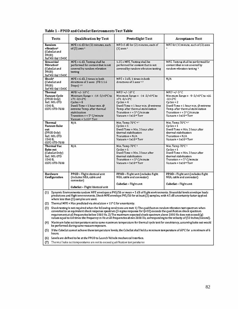
82

83
6.3.7 PPOD door release must be designed to accept redundantly initiated signals
6.4.4 LV shall accommodate PPOD door position indicator in the flight telemetry
stream.
6 .4.5 LV avionics shall provide redundant-separation signals to the PPOD door
actuation device.
6.4.9 LV shall command deployment of the PPOD’s CubeSats.
6 4.10 LV trajectory design shall not result in LV contact with deployed CubeSats
6.4.11 LV shall not deploy the CubeSats in a trajectory that will contact the Primary
Mission or LV
6.3.15 PPOD must have a fixed base frequency > 120 Hz
7. Development of Mission/Ground Operations Plan
a. Identification of pre-launch activities (functional tests, handling, etc.) and
requirements (basic facilities, time needed, etc.)

84
b. Description of spacecraft operations plan post LV-separation (particularly
transmitter initialization and first contact)
DNEPR Safety Compliance Requirements [34]
2. Thermal Vacuum Compliance
Thermal-vacuum bakeouts are critical in assemblies of space flight hardware to ensure the lowest
levels of outgassing. Thermal bakeout of smaller subassemblies and components help reduce
overall bake time and decrease the final levels of outgassing. A minimum vacuum level of 5 x
10-4
Torr must be attained to observe the outgassing of components.
Note: NASA certified materials should always be used in space flight hardware, especially
epoxies and glue. If in doubt about the materials you are using, please contact the CubeSat
Coordinator. Thermal-vacuum bakeout must be performed on fully integrated flight
CubeSats before integration into the P-POD.
2.1 How to Test
2.1.1 Please read and understand all steps before performing any actions.
2.1.2 Clean the external surface of all hardware with lint free wipes and lab grade
isopropyl alcohol before inserting the hardware into the thermal-vacuum chamber.
2.1.3 Place the clean hardware into the thermal-vacuum chamber.
2.1.4 Bring the chamber to a vacuum level of at least 5 x 10⁻⁴
Torr. Outgassing will be
easily observed at higher vacuum levels.
2.1.5 Record the initial pressure level and temperature in the Bakeout Compliance
Checklist attached at the end of this document.
2.1.6 Starting at room temperature, approximately 25°C raise the temperature of the
shroud or heating element to 70°C.
2.1.7 As temperature is increasing, record the pressure level along with the
corresponding temperature every 20 minutes.

85
2.1.8 Wait until the exterior surface of the hardware has reached 70°C. Note: There may
be an initial increase in pressure, this is to be expected.
2.1.9 Let the hardware bake at 70°C for one hour.
2.1.10 Record the temperature and pressure every 10 minutes during this first bake,
making note of any unusual pressure readings.
2.1.11 If you do not wish to bring your flight hardware to 70°C, you may set the upper
temperature extreme to 60°C. However, you must let the hardware bake for two
hours.
2.1.12 Bring the chamber and hardware back to room temperature.
2.1.13 As temperature is decreasing, record the pressure and temperature every 20
minutes.
2.1.14 Keep the shroud and hardware at room temperature for one hour.
2.1.15 Record the pressure and temperature every 20 minutes.
2.1.16 Bring the shroud and hardware back up to 70°C for the final bakeout.
2.1.17 As the temperature increases, record the pressure and temperature every 20
minutes.
2.1.18 Let the hardware bake for one hour at 70°C.
2.1.19 Record the pressure and temperature every 10 minutes.
2.1.20 If you do not wish to bring your flight hardware to 70°C, you may set the upper
temperature extreme to 60°C. However, you must let the hardware bake for two
hours.
This will eliminate most of the outgassing that will occur at this temperature
extreme. The pressure should remain constant and should not exceed + 1 x 10 -4

86
Torr from the original pressure at room temperature. If the pressure does increase,
longer thermal baking is needed until the pressure stabilizes. The shroud and
hardware are now brought back to room temperature.
2.1.21 Thermal bakeout is now complete.
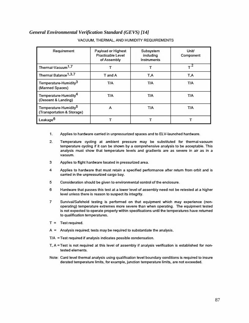
87
General Environmental Verification Standard (GEVS) [14]
88
STANDARD MATERIALS AND PROCESSES REQUIREMENTS FOR SPACECRAFT
National Aeronautics and Space Administration, Washington, DC 20546-0001 [3]
4 .1.1.4 Commercial Off-The-Shelf (COTS) Hardware
a. A procedure shall be established to ensure that all vendor-designed, off-the-
shelf, and vendor-furnished items are covered by the M&P requirements of this
document.
b. The procedure shall include special considerations for off-the-shelf hardware
where detailed M&P information may not be available or it may be impractical
to impose all the detailed requirements specified in this standard.
c. The procedure shall include provisions for ensuring that this hardware is
satisfactory from an overall M&P standpoint.
NASA Procedural Requirements for Limiting Orbital Debris (w/ Change 1 - 5/14/09) (limiting
orbital debris) [8]
3.1.2 The NASA Program/Project Manager, with the NASA Center SMA
organization, shall track and monitor the noncompliances (to this NPR and NSS
1740.14 or NASA-STD 8719.14, as applicable per paragraph P.2.4) with the
design and operations of the spacecraft and orbital launch vehicle stages
beginning at PDR and shall have the tracking reviewed by the Center SMA
organization prior to CDR and launch ( Requirement 57313).
3.3.1.3 When significant capabilities affecting the spacecraft's planned ability to
passivate, maneuver, or reenter at end-of-life change either through graceful
degradation, malfunction, or via command, the EOMP shall be
updated/annotated by the NASA Program/Project Manager ( Requirement
56867).
3.3.2.5 The NASA Program/Project Manager shall ensure that all spacecraft and launch
vehicles designed to be operated in GEO are designed to be able to maneuver at
least 300 km above GEO altitude (closest approach to GEO greater than 300 km
above GEO altitude) ( Requirement 56882).
89
3.4 Conjunction Assessments during Mission Operations (for Earth-Orbiting
Spacecraft)
3.4.1 The NASA Program/Project Manager shall have conjunction assessment
analyses performed routinely for all maneuverable Earth-orbiting spacecraft with
a perigee height of less than 2000 km in altitude or within 200 km of GEO
( Requirement 56891).
3.4.2 Conjunction assessment analyses shall be performed using the USSTRATCOM
high-accuracy catalog as a minimum (Requirement 56892).
3.4.3 The NASA Program/Project Manager shall have a collision risk assessment and
risk mitigation process in place for all maneuverable Earth-orbiting spacecraft
that are performing routine conjunction assessment analyses ( Requirement
56893).
LAUNCH SAFETY REQUIREMENTS FOR AIR FORCE SPACE COMMAND
ORGANIZATIONS [4]
6.1. Flight Safety System Composition. The entire FSS consists of the airborne and
ground FTSs, air- borne and ground tracking systems, and airborne and ground
telemetry data transmission systems. This publication only addresses the
Launch Safety requirements for the ground components of the FSS.
Requirements for the airborne components of the FSS are in AFSPCMAN 91-
710. The ground element of the FSS consists of the TDTS, the RTS, and the
FTS. The RTS includes a RSD system, which displays vehicle flight
performance data that the MFCO uses as the basis for a flight termination
decision. The TDTS provides for the transport of onboard launch vehicle
position and performance data to the RSD and the Range User. The CDS
provides the MFCO the capability to terminate the vehicle’s flight.
6.4. RTS Requirements. An RTS is composed of the hardware, software, and
manpower required to transmit, receive, process, and display selected launch
vehicle data. This data, when qualified as described below, allows a MFCO to
compare actual and nominal flight trajectories, verify performance in
conjunction with vehicle telemetry, and identify violations of destruct criteria.

90
With this information, the MFCO knows when a flight rule has been violated
and flight termination actions are required.
6 .5. TMIG Data as a Metric Tracking Source. TMIG data is a mandatory tracking
source for pro- grams using a launch vehicle inertial guidance system when
validated by the AFSPC range or certified to the RCC Standard 324. The
TMIG data is required at a 10 samples per second update rate from T-0
through the end of Wing Safety responsibility.
6.7.1. An RSD system is required as the primary information display system used by
the MFCO to evaluate launch vehicle flight.
6.7.2. Flight Analysis (a part of the Launch Safety Section of Wing Safety) shall
provide RSD requirements, instructions, and data necessary for display
generation to range personnel responsible for RSD systems operations.
6.7.3. Real-Time Prediction Requirements.
6.7.3.1. PP and IIP solutions shall be provided for display on the RSD at a rate of 10
samples per second or faster.
6.7.3.2. The PP and IIP solutions shall be computed from data supplied by the tracking
sources identified in the RSOR and/or its operational supplement as applicable.
6.7.3.3. PP and IIP computations and displays shall be single failure tolerant.
6.7.3.4. Range specific real-time calculated IIP accuracy requirements are provided in
AFSPC- MAN 91-710 and the SW supplements to AFSPCMAN 91-711.
6.7.3.5. Velocity vs. time, altitude, fast/slow time relative to nominal, plus count time,
dynamic nominal and other data identified in the RSOR shall also be displayed.
6.7.4. Wing unique RSD requirements shall be included in the respective wing
supplement to AFSPCMAN 91-711.
6.7.5. Video Display Requirements.
6.7.5.1. Video monitors with channel switching capability shall be provided to the
MFCO and Senior MFCO positions.
6.7.5.2. Specific video coverage requirements peculiar to a mission shall be
identified in the RSOR for the vehicle or the Ops Sup for the mission.
6.7.6. Telemetry Display Requirements.
91
6.7.6.1. Specific telemetry display requirements shall be documented in the RSOR or Ops
Sup for a mission.
6.10. Telemetry Systems. Real-time information on in-flight vehicle performance and
behavior typically includes but is not limited to, engine chamber pressures, roll
rate, attitude, launch vehicle velocity vs. time, automatic gain control values of
the command destruct receivers, and occurrence of discrete event. Additional
telemetry system requirements are provided in the SW supplements to
AFSPCMAN 91-711 and the program specific RSOR.
7.1.3. Command Capability. AFSPC ranges shall ensure that range managed
instrumentation pro- vides uninterrupted command capability for all systems
that use an FTS or thrust termination system. For systems that use command
receiver decoders, capture from FTS turn-on through flight control end of
mission is required.
7.4.1. The Flight Control communication circuit requirements shall be specified in
the applicable RSOR, Ops Sup, or operations directive (OD).

92
Appendix 2: Definition of Key Terms
• 2D: Two-Dimensional
• 2U: Two Unit
• 3D: Three-Dimensional
• 3U: Three Unit
• ADC: Attitude Determination and Control
• AFSK: Audio Frequency Shift Keying
• AGI: Analytical Graphics Inc.
• Bandwidth: The maximum change in frequency for a continuous set of frequencies.
• BCR: Battery Charge Regulator
• BER: Bit Error Rate - The number of altered or incorrect bits, caused by interference,
distortion, or noise, divided by the total number of bits in an interval of time.
• BPSK: Binary Phase Shift Keying - Form of phase modulation where the signal phase
can be one of 2 possible values.
• C/N: Carrier to noise radio dependent on bandwidth.
• C/No: Carrier to noise ratio independent of bandwidth.
• CAD: Computer-Aided Design
• Cal Poly: California Polytechnic State University
• CDMA: Code Division Multiple Access- Multiple Access technique which uses a PN
code to spread a narrow band signal over a wider band.
• COTS: Commercial Off-The-Shelf
• DAQ: Data Aquisition
• DCGS: Delft Command Ground Station
• DNEPR: Russian launch vehicle. Carried 14 CubeSats but failed to launch.
• Eb/No: Receiver bit energy to noise ratio.
• EHF: Extremely High Frequency
• EIRP: Effective Isotropically Radiated Power- The amount of power that a theoretical
isotropic antenna would emit to produce the peak power density observed in the direction
of maximum antenna gain. Measured as the transmitter power plus the antenna gain
minus line losses.
• EoC: End of Charge

93
• EOM: End of Mission
• EPS: Electrical Power System
• FCC: Federal Communications Commission
• Flux Density: The transmitter’s radiated power over the surface area of a sphere whose
radius equals the distance between the transmitter and receiver.
• FSK: Frequency Shift Keying - Modulation technique in which digital information is
carried by discrete changes in frequency of a carrier wave.
• g/T: Ratio of gain over temperature.
• GENSO: Global Educational Network for Satellite Operations
• GPS: Global Positioning System
• Ground Tracks- projection of the satellite's orbit onto the surface of the Earth
• H1: Header 1
• I2C: Inter Integrated Circuit- Consists of a data line and a clock line, allowing for a
connection of a low speed device to a motherboard or an embedded system.
• ICD: Interface Control Document
• LNA: Low Noise Amplifier- Low gain amplifier optimized to minimize the amount of
noise the amplifier adds to the signal.
• LV: Launch Vehicle
• Mbps: Mega Bytes per Second
• MPE: Maximum Predicted Environment
• MPPT: Maximum Power Point Tracking
• MQP: Major Qualifying Project
• MUA: Material Usage Agreement
• NASA: National Aeronautical Space Association
• OBC: On Board Computer
• PCB: Printed Circuit Board
• PCM: Power Conditioning Modules
• PDM: Power Distribution Module
• PMAD: Power Management and Distribution
• P-POD: Poly-Picosatellite Orbital Deployer
94
• QPSK: Quadrature Phase Shift Keying - Form of Phase Modulation in which the carrier
phase can be one of 4 possible phases. Has the same Bit error rate as BPSK but for 1/2
the bandwidth.
• R.A.A.N : Relative Angle of the Ascending Node
• RBF: Remove Before Flight
• RF: Radio Frequency
• RIP: Received Isotropic Power- The power of a signal at the receiving station relative to
an isotropic antenna. Computed by taking the EIRP and subtracting the free space loss,
atmospheric loss, and pointing loss.
• SA: Solar Array
• S-Band: IEEE standard for radio waves (frequencies that range from 2000 to 4000 MHz)
• SHF: Super High Frequency
• STK: Systems Took Kit
• TBD: To Be Determined
• TVB: Thermal Vacuum Bakeout
• UHF: Ultra High Frequency (frequencies that range from 300 to 3000 MHz)
• USAF: United Stated Air Force
• USB: Universal Serial Bus
• VHF: Very High Frequency (frequencies that range from 30 to 300 MHz)
• WPI: Worcester Polytechnic Institute, Worcester, Massachusetts
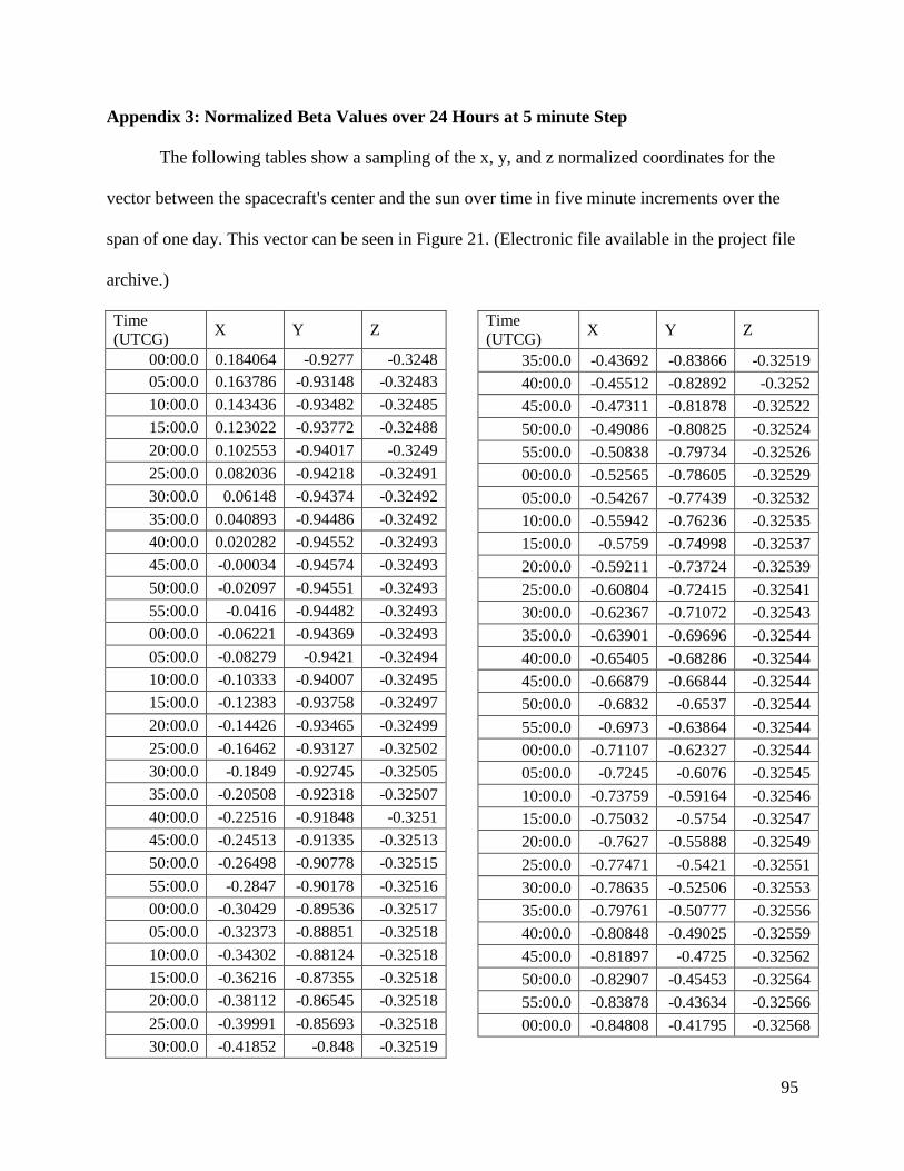
95
Appendix 3: Normalized Beta Values over 24 Hours at 5 minute Step
The following tables show a sampling of the x, y, and z normalized coordinates for the
vector between the spacecraft's center and the sun over time in five minute increments over the
span of one day. This vector can be seen in Figure 21. (Electronic file available in the project file
archive.)
Time (UTCG) X Y Z
00:00.0 0.184064 -0.9277 -0.3248 05:00.0 0.163786 -0.93148 -0.32483 10:00.0 0.143436 -0.93482 -0.32485 15:00.0 0.123022 -0.93772 -0.32488 20:00.0 0.102553 -0.94017 -0.3249 25:00.0 0.082036 -0.94218 -0.32491 30:00.0 0.06148 -0.94374 -0.32492 35:00.0 0.040893 -0.94486 -0.32492 40:00.0 0.020282 -0.94552 -0.32493 45:00.0 -0.00034 -0.94574 -0.32493 50:00.0 -0.02097 -0.94551 -0.32493 55:00.0 -0.0416 -0.94482 -0.32493 00:00.0 -0.06221 -0.94369 -0.32493 05:00.0 -0.08279 -0.9421 -0.32494 10:00.0 -0.10333 -0.94007 -0.32495 15:00.0 -0.12383 -0.93758 -0.32497 20:00.0 -0.14426 -0.93465 -0.32499 25:00.0 -0.16462 -0.93127 -0.32502 30:00.0 -0.1849 -0.92745 -0.32505 35:00.0 -0.20508 -0.92318 -0.32507 40:00.0 -0.22516 -0.91848 -0.3251 45:00.0 -0.24513 -0.91335 -0.32513 50:00.0 -0.26498 -0.90778 -0.32515 55:00.0 -0.2847 -0.90178 -0.32516 00:00.0 -0.30429 -0.89536 -0.32517 05:00.0 -0.32373 -0.88851 -0.32518 10:00.0 -0.34302 -0.88124 -0.32518 15:00.0 -0.36216 -0.87355 -0.32518 20:00.0 -0.38112 -0.86545 -0.32518 25:00.0 -0.39991 -0.85693 -0.32518 30:00.0 -0.41852 -0.848 -0.32519
Time (UTCG) X Y Z
35:00.0 -0.43692 -0.83866 -0.32519 40:00.0 -0.45512 -0.82892 -0.3252 45:00.0 -0.47311 -0.81878 -0.32522 50:00.0 -0.49086 -0.80825 -0.32524 55:00.0 -0.50838 -0.79734 -0.32526 00:00.0 -0.52565 -0.78605 -0.32529 05:00.0 -0.54267 -0.77439 -0.32532 10:00.0 -0.55942 -0.76236 -0.32535 15:00.0 -0.5759 -0.74998 -0.32537 20:00.0 -0.59211 -0.73724 -0.32539 25:00.0 -0.60804 -0.72415 -0.32541 30:00.0 -0.62367 -0.71072 -0.32543 35:00.0 -0.63901 -0.69696 -0.32544 40:00.0 -0.65405 -0.68286 -0.32544 45:00.0 -0.66879 -0.66844 -0.32544 50:00.0 -0.6832 -0.6537 -0.32544 55:00.0 -0.6973 -0.63864 -0.32544 00:00.0 -0.71107 -0.62327 -0.32544 05:00.0 -0.7245 -0.6076 -0.32545 10:00.0 -0.73759 -0.59164 -0.32546 15:00.0 -0.75032 -0.5754 -0.32547 20:00.0 -0.7627 -0.55888 -0.32549 25:00.0 -0.77471 -0.5421 -0.32551 30:00.0 -0.78635 -0.52506 -0.32553 35:00.0 -0.79761 -0.50777 -0.32556 40:00.0 -0.80848 -0.49025 -0.32559 45:00.0 -0.81897 -0.4725 -0.32562 50:00.0 -0.82907 -0.45453 -0.32564 55:00.0 -0.83878 -0.43634 -0.32566 00:00.0 -0.84808 -0.41795 -0.32568

96
Appendix 4: Lab Option Hardware List
The following are images and details for the equipment purchased for the vacuum chamber experiment.
Halogen Lamp & Bulb [35]
Workforce 250-Watt Halogen Portable Work Light Home Depot Model # 778-980, Home Depot Store SKU # 778980 $8.99
Aluminum Sheet [36]
Alloy 3003 Aluminum Sheet Dimensions: Thickness: 0.0252 in Width: 12 in Length: 12 in MSC Industrial Supply Co. MSC #: 09426057 $4.52 PCB [37]
PCBs / Circuit Boards Single-Sided Copper Clad Dimensions: Thickness: 1/32 in Width: 6 in Length: 9 in Distributor: Mouser Electronics Mouser Part #: 590-588 $7.46

97
Thermocouples [38]
Ready-Made Insulated Thermocouples with Kapton®, PFA, Glass Braid Insulation and Molded Connectors Thermocouple, type k, insulate (glass braid), exposed junction AWG Gage: 24 Diameter: 0.020 in Miniature connector Omega Part Number: 5SRTC-GG-(K)-24-(36) $50.00 Extension Wires [39]
24 Gage Solid Thermocouple Wire with FEP Insulation and Jacket, K-type McMaster-Carr Part Number: 3870K32 $1.20/ft. Connectors for the thermocouples to the chamber feedthroughs [40]
Panel-Mount Thermocouple Female Connectors Panel Cutout: 7/8 in. diameter McMaster-Carr Part Number: 3869K48 $10.82
Chamber electrical feedthrough [41]
Power Feedthroughs - Weldable 500 Volts Stainless Steel – 4 pins Kurt J. Lesker Co. Part Number: EFT0042031 $81.50

98
Appendix 5: WPI Ground Station
Below are two cost estimates of all required hardware, excluding the antenna, needed to
create a WPI Ground Station. The difference between Upper and Lower is simply pricing. All
part numbers are the same between the two, Lower is the used version of the parts. The decision
to show two different cost estimates was to establish a range of possible totals for all hardware.
Upper values are all new parts from the manufacturer or commercial sources, while Lower is
used hardware from various different places. In the event that a cheaper used part is unavailable,
the Upper value will be available.
Cost Analysis (Upper) part use cost
ICOM CIV radios IC9100 Radio $3,349.95 Yaesu G5500 rotor $749.95 Yaesu G5500 sep kit $24.00 Rotor Controller GS-232B controller $ 870 ST-1 Rotor Controller $ 45 K9612+ (Kantronics) TNC $ 400 MixW TNC Free K8055 (Velleman) Switch $ 58 SP7000 SSB ELECTRONICS amp $ 412 Ground Station Control Computer comp $ 1300 1 Terabyte External Hard drive comp $ 85 Linux Laptops for SDR Control comp $ 1100 Kantronics 3 plus Modem comp $ 200 Wireless Network Router BEFSR41 comp $ 11 Uninterruptable Power Supply 1000AVR power $ 150 12 Volt Power supply 1692 power $ 345 RF Directional Thruline Watt Meter Mdl. 43 power $ 350 USRP-2 SDR interface $ 650 USRP-1 SDR interface $ 700 USRP daughter board WBX interface $ 450 USRP daughter board TVRX interface $ 200 (2) Coax protectors Polyphaser IS-50NX-C2 Lightning suppressors lightning rod $ 63
(2) Cable protectors Polyphaser IS-RCT Lightning suppressors lightning rod $ 133
$11,646
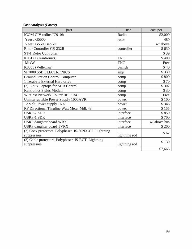
99
Cost Analysis (Lower) part use cost per
ICOM CIV radios IC910h Radio $2,000 Yaesu G5500 rotor 480 Yaesu G5500 sep kit
w/ above
Rotor Controller GS-232B controller $ 630 ST-1 Rotor Controller
$ 39
K9612+ (Kantronics) TNC $ 400 MixW TNC Free K8055 (Velleman) Switch $ 40 SP7000 SSB ELECTRONICS amp $ 330 Ground Station Control Computer comp $ 800 1 Terabyte External Hard drive comp $ 70 (2) Linux Laptops for SDR Control comp $ 302 Kantronics 3 plus Modem comp $ 30 Wireless Network Router BEFSR41 comp Free Uninterruptable Power Supply 1000AVR power $ 100 12 Volt Power supply 1692 power $ 345 RF Directional Thruline Watt Meter Mdl. 43 power $ 155 USRP-2 SDR interface $ 850 USRP-1 SDR interface $ 700 USRP daughter board WBX interface w/ above bus USRP daughter board TVRX interface $ 200 (2) Coax protectors Polyphaser IS-50NX-C2 Lightning suppressors lightning rod $ 62
(2) Cable protectors Polyphaser IS-RCT Lightning suppressors lightning rod $ 130
$7,663

100
Appendix 6: Other Ground Station Hardware The following tables are compilations of the hardware and software being used by each
of the ground stations that have been used in calculating the ground tracks and data link budget.
The information was used to determine antenna information for the data information. The lists
were also used in determining hardware for the proposed WPI Ground Station. By using similar
or the same hardware and software, the ground stations will more easily be able to communicate.
Nicolaus Copernicus Astronomical Center, Warsaw University of Technology, Warsaw, Poland [42].
hardware use two Yagi- Uda antennas for UHF Antenna structure 10 feet Tower 2.08m parabolic dish (Figure 4) with a right-hand circularly polarized feed is used to receive the S-Band Andersen Manufacturing Antenna Two 435MHz 42-element circularly polarized (with polarization switch) Yagi- Uda UHF signal. Antenna single Yagi- Uda antenna VHF Antenna S-Band signal PSM-4900 by Datum Systems. Radio Half-duplex Yaesu FT-897 amateur transceiver UHF link. Radio VHF radio Yaesu FT-847 Radio Rotator AlfaSpid Radio full Azimuth/Elevation design. Rotator Custom designed microcontroller uses a simple 8-bit microcontroller (uC), the ATmega32. Controller A pair of low-cost H-Bridge motor Motor 200MHz ARM Single Board Computer (SBC) by Technological Systems Computer
Linux operating system
SCC PEB20525 Serial Communications Controller Controller Rotator Interface RS-422 interface Interface S-Band Modem Interface Interface Since the TNC control board
S-Band modem (DATUM Systems PS2100 Modem UHF Modem CMX589 synchronous GMSK Modem RS-232 serial ports interface with the UHF radio. Interface “Plan13” algorithm fed by NORAD TLE’s. A set of scripts have been developed that interface with the SpaceTrack website to automatically retrieve new NORAD TLE’s. Software Operator Interface Software created “Nanosatellite Interface Control Environment (NICE)”. NICE was Software The Terminal Interface Program (TIP) created Software

101
Delft Command Ground Station (DCGS), Delft University of Technology, Delft, Netherlands [43]
*The ISIS ground station kit has been designed to be compatible with the Global Educational Network for Satellite Operations (GENSO)
hardware Use 38k4 FSK TNC TNC 12-U 19” rack which allows the ground station to fit in almost any location. Tower VHF Yagi antenna Antenna UHF Yagi antenna Antenna VHF Low Noise Amplifier Amp UHF Low Noise Amplifier Amp 21dBic gain S-band parabolic reflector Antenna Lightning protection system lightning Heavy duty all-weather azimuth – elevation rotator Rotator Terminal Node Controllers (TNC’s) for 1200-9600bd AX.25 AFSK, FSK and BPSK TNC 38k4 FSK Terminal Node Controller (TNC) and high speed modification of ground station transceiver option available TNC Uninterruptible Power Supply Power Industrial rackmount PC with Computer tracking software Software
FASTRAC, University of Texas at Austin, Austin, Texas [44]. hardware use
Windows HyperTerminal software MacDoppler for Cocoa software MixW TNC ONEStop software two UHF/VHF Yagi antenna IC-910H radio ICOM PS-125 radio Astro Dev Helium 100
Hamtronics r100 VHF FM RECIEVER radio MO-96 9600 baud modem kit modem Kantronics KPC-9612+ TNC Hamtronics ta451 modification kit modem modifier Hamtronics r451 modification kit modem modifier Hamtronics crystals
tantalum caps

102
Cal Poly Earth Station – N6CP, California Polytechnic State University, San Luis Obispo, California [45].
hardware use Chipcon CC1000 Software Yaesu FT-847 radio Radio cc1000.c Software Microchip PIC18LF6720 Chip KPC9612+ [23] Interface MixW TNC RF Microdevices RF2117 Chip Yaesu 847 radio Radio 2m and 70cm Yagi Antenna HF antenna. Antenna Tower Rohn JRM23810 non-penetrating roof mount. Tower Yaesu G-5500 rotor system Rotator M-squared 436CP42 antenna is used for 70cm Antenna SSB Electronics preamplifier Amp LMR-400 coax Cable 50 foot run of 5/8″ heliax goes thru Cable 1200 baud can be just straight speaker audio (after the filters) Interface 9600 baud data must be taken before the filters (discriminator-tapped). Interface CAT interface FT-847 Interface DB-9 serial port needs null-modem adapter
standard PC Computer
WindowsXP operating system
MixW TNC COM port drivers
MacDopplerPRO (Dog Park Software) Software two Mac computers (MacOS X) Computer SatPC32 Software · Predict by John A. Magliacane, KD2BD. This is a small terminal-based prediction program that will work on *nix and DOS platforms. It has a very clean and clear interface, and will run over an SSH connection. It will even run on the built-in terminal in MacOS X. Software · Instant Track from AMSAT. This is a DOS-only program. It can run on current machines, but has trouble with the screen. If you have an old DOS computer, drop this on it and practice tracking some satellites. Make sure to read the README documents. Software · Space Track - The official Keplerian Elements source. Requires free registration.
locating software
· AMSAT - Keplerian Elements for all the amateur satellites in 2-line format.
locating software
· Celestrak - Another distributor of elements.
locating software

103
Appendix 7: Complete Hardware Parts List with Images
The table below is a hardware and parts list for the major components required to
implement the CubeSat mission. This includes on-board ADC, Power, and Communication parts,
and the ground station hardware and software.
Group Component Company Part Number Image OBC OBC Tyvak Intrepid
[20] ADC board ClydeSpace CS-ADCS-INT-01
[30] Course Sun Sensor (3 or
5)
ComTech AeroAstro
CubeSat Sun Sensor
[9] Fine Sun Sensor
SSBV Space and Ground
Systems Fine Sun Sensor
Gyro Analog Devices ADXRS450
[22]
ADC
[46] Magnetic Torquers (3)
Zarm Technik AG
MTO 5.0 (Optimized)
[24] Magnetometer Honeywell HMC5883L

104
[25] GPS
Surrey Satellite
Technology US LLC
SGR-05U
Payload Instrument Sphinx NG - XRAY
[6] EPS Board ClydeSpace CS-3UEPS2-NB
[7] PDM Board ClydeSpace CN-SWT-0035-
CS
Power
[26] Battery ClydeSpace CS-SBAT2-30
[47] Battery Charge Cord FTDI Chip FTDI USB-
RS422-WE
[48] Battery
Charge Cord Adapter
Bravekit FTDI UM232R
[27] Front Solar
Panels ClydeSpace SP-L-F2U-0033-CS
[28] Side Solar Panels ClydeSpace SP-L-S2U-0031-
CS

105
[10] UHF Transceiver ISIS Transceiver
Communicati
on UHF
Transceiver ISIS Antenna
[49] IC910 ICOM Radio
Ground Station
MercuryRotor driver. YASU rotor
[50]
K9612+ the two ports (1200 & 9600)
Kantronics
[51] MixW TNC
[52] K8055 (Velleman) Velleman
[53] SP7000 SSB ELECTRONICS

106
[54] Yaesu G-5500 AZ/EL Yaesu Controller
Ground Station Control Computer
Control
Computer
1 Terabyte External Hard
Drive
Linux Laptop (SDR Control)
[55] BEFSR41 Wireless
Network Router
Uninterruptable 1000AVR Power Supply
1692 12 Volt Power supply
1460 1PS 12 Volt Power supply
[56, 57]
RF Directional Thruline Watt Meter Mdl. 43
[58] USRP-B100
[58] USRP-1 SDR

107
[58] WBX USRP daughter board
[58] TVRX USRP daughter board
[59]
(2) Coax protectors Polyphaser IS-50NX-C2
Lightning suppressors
[60]
(2) Cable protectors Polyphaser IS-RCT
Lightning suppressors

108
Appendix 8: CubeSat Bus Wiring Diagrams
This appendix provides a labeling of all the connection points between the CubeSat bus
and the devices attached to the CubeSat. Below are the figures that show the locations of the
headers, the pins of the headers, and the labeling of the wires or connection points of the devices.
Figure 34: Vertical Board Stack (Side Images of boards adapted from [7], [6] and [26])
H2 2 4 6 8 10 12 14 16 18 20 22 24 26 28 30 32 34 36 38 40 42 44 46 48 50 52
1 3 5 7 9 11 13 15 17 19 21 23 25 27 29 31 33 35 37 39 41 43 45 47 49 51 H1 2 4 6 8 10 12 14 16 18 20 22 24 26 28 30 32 34 36 38 40 42 44 46 48 50 52 1 3 5 7 9 11 13 15 17 19 21 23 25 27 29 31 33 35 37 39 41 43 45 47 49 51
Figure 35: CubeSat Bus's Pin and Header Labeling

109
Figure 36: Solar Array Wire Labeling (adapted from [6])
Figure 37: SA Connector Location and Labeling (adapted from [6])

110
Figure 38: SA Connector Pin Labeling (adapted from [6])
Figure 39: Gyroscope's Mounting Board Wire Connection Labeling (adapted from [61])

111
Figure 40: Magnetometer's Mounting Board Wire Connection Labeling (adapted from [62])
Figure 41: Coarse Sun Sensor's Wire Labeling (adapted from [21])
Figure 42: GPS's Wire Labeling (adapted from [63])

112
Appendix 9: CubeSat Bus Power Board Pin Assignments
This appendix details the connections between the 104 pins of the two headers of the
CubeSat bus and devices attached to the CubeSat using the labeling conventions described in
Appendix 8. The first two tables describe the purpose of each pin of each header of the CubeSat
bus and where they connect to. The third table describes the connections between the devices and
either the ADC board or the CubeSat bus.
Table 9: CubeSat Bus, Header 1 SW=Switch AI=Analog Input -=Not Applicable ( )=Originating Board, Device Pin Purpose Maximum
Voltage (V)
Maximum Current (A)
Connection References
1 SW: 19, (PDM)
8.3 4 - [7]
3 SW: 19, (PDM)
8.3 4 - [7]
5 SW: 22, (PDM)
opt+2.5% 4 - [7]
7 AI: GND, (EPS)
3 - board stack connection only [7], [6]
9 AI: GND, (EPS)
3 - board stack connection only [7], [6]
11 AI: GND, (EPS)
3 - board stack connection only [7], [6]
13 - - - - [7], [6] 15 - - - - [7], [6]
17 AI: GND, (EPS)
3 - board stack connection only [7], [6]
19 AI: +Y CURRENT, (EPS, Solar Array)
3 - board stack connection only [7], [6]
21
AI: +Y TEMPERATURE, (EPS, Solar Array)
3 - board stack connection only [7], [6]
23
AI: Y PAIR VOLTAGE, (EPS, Solar Array)
3 - board stack connection only [7], [6]
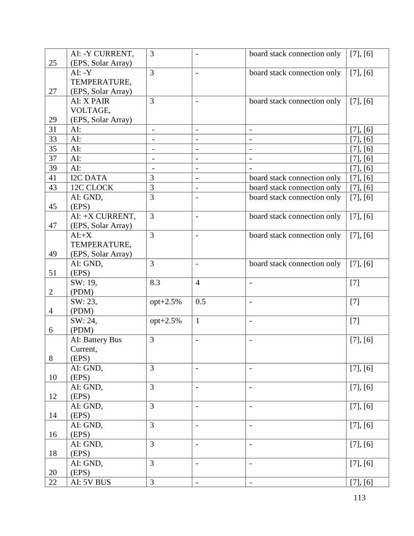
113
25 AI: -Y CURRENT, (EPS, Solar Array)
3 - board stack connection only [7], [6]
27
AI: -Y TEMPERATURE, (EPS, Solar Array)
3 - board stack connection only [7], [6]
29
AI: X PAIR VOLTAGE, (EPS, Solar Array)
3 - board stack connection only [7], [6]
31 AI: - - - [7], [6] 33 AI: - - - [7], [6] 35 AI: - - - [7], [6] 37 AI: - - - [7], [6] 39 AI: - - - [7], [6] 41 I2C DATA 3 - board stack connection only [7], [6] 43 12C CLOCK 3 - board stack connection only [7], [6]
45 AI: GND, (EPS)
3 - board stack connection only [7], [6]
47 AI: +X CURRENT, (EPS, Solar Array)
3 - board stack connection only [7], [6]
49
AI:+X TEMPERATURE, (EPS, Solar Array)
3 - board stack connection only [7], [6]
51 AI: GND, (EPS)
3 - board stack connection only [7], [6]
2 SW: 19, (PDM)
8.3
4 - [7]
4 SW: 23, (PDM)
opt+2.5% 0.5 - [7]
6 SW: 24, (PDM)
opt+2.5% 1 - [7]
8
AI: Battery Bus Current, (EPS)
3 - - [7], [6]
10 AI: GND, (EPS)
3 - - [7], [6]
12 AI: GND, (EPS)
3 - - [7], [6]
14 AI: GND, (EPS)
3 - - [7], [6]
16 AI: GND, (EPS)
3 - - [7], [6]
18 AI: GND, (EPS)
3 - - [7], [6]
20 AI: GND, (EPS)
3 - - [7], [6]
22 AI: 5V BUS 3 - - [7], [6]

114
CURRENT, (EPS)
24
AI: 3.3V BUS CURRENT, (EPS)
3 - - [7], [6]
26 AI: GND, (EPS)
3 - - [7], [6]
28 AI: GND, (EPS)
3 - - [7], [6]
30 AI: (EPS)
- - - [7], [6]
32 AI: (EPS)
- - - [7], [6]
34 RS232RX - - - [7] 36 RS232TX - - - [7] 38 serial RX1 - - - [7] 40 serial TX1 - - - [7] 42 serial RX2 - - - [7] 44 serial TX2 - - - [7] 46 serial RX3 - - - [7] 48 Serial TX3 - - - [7] 50 Serial RX4 - - - [7] 52 Serial TX4 - - - [7]
Table 10: CubeSat Bus, Header 2 SW=Switch AI=Analog Input -=Not Applicable ( )=Originating Board, Device
Pin Purpose Maximum Voltage (V)
Maximum Current (A)
Connection References
1 SW: 1, (PDM)
3.33 0.5 Magnetometer [7], [62]
3 SW: 3, (PDM)
3.33 0.5 - [7]
5 SW: 5, (PDM)
3.33 1 - [7]
7 SW: 7, (PDM)
3.33 4 - [7]
9 SW: 7, (PDM)
3.33 4 - [7]
11 SW: 9, (PDM)
5.05 0.5 - [7]

115
13 SW: 11, (PDM)
5.05 1 Magnetic Torquer 1 [7], [23]
15 SW: 13, (PDM)
5.05 1 Magnetic Torquer 3 [7], [23]
17 SW: 14, (PDM)
5.05 4 - [7]
19 SW: 15, (PDM)
8.3 (BATT) 0.5 - [7]
21 SW: 17, (PDM)
8.3 (BATT) 1 Payload [7]
23 SW: 20, (PDM)
opt + 2.5% - - [7]
25 5V, (EPS)
5V - Board Stack Connection Only
[6]
27 3.3V, (EPS)
3.3V - Board Stack Connection Only
[6]
29 GND, (EPS)
- - Magnetic torque 1-3, CubeSat Sun Sensor
[6], [30], [23]
31 AGND, (EPS)
- - Board Stack Connection Only
[6]
33 Batt POS, (EPS)
- - DO NOT CONNECT [6]
35 PCM IN, (EPS)
- - Deployment Switch 1 & 2: input to PCM’s and PDM (switch on state), Power Flow to Board Stack
[6]
37 Dummy Load, (EPS)
- - Pull pin inserted: off state [6]
39 - - - Unused Connection (Deployment switch 1 & 2: off state)
[6]
41 BCR Out, (EPS)
- - BCR out to Deployment Switches
[6]
43 BCR Out, (EPS)
- - BCR out to Deployment Switches
[6]
45 BATTERY - - Board Stack Connection Only
[6]
47 RS422 RXA - - - [7] 49 RS422 RXB - - - [7] 51 OPTIONAL
V - - - [7]
2 SW: 2, (PDM)
3.33 0.5 - [7]
4 SW: 4, (PDM)
3.33 1 - [7]

116
6 SW: 6, (PDM)
3.33 1 - [7]
8 SW: 7, (PDM)
3.33 4 - [7]
10 SW: 8, (PDM)
5.05 0.5 CubeSat Sun Sensor [7], [30]
12 SW: 10, (PDM)
5.05 0.5 Gyroscope [7], [61]
14 SW: 12, (PDM)
5.05 1 Magnetic Torquer 2 [7], [23]
16 SW: 14, (PDM)
5.05 4 GPS (red 1) [7], [63]
18 SW: 14, (PDM)
5.05 4 GPS (red 2) [7], [63]
20 SW: 16, (PDM)
8.3 (BATT) 0.5 - [7]
22 SW: 18, (PDM)
8.3 (BATT) 1 - [7]
24 SW: 21, (PDM)
opt + 2.5% - - [7]
26 5V - - Board Stack Connection Only
[6]
28 3.3V - - Board Stack Connection Only
[6]
30 GND - - Magnetometer; CSS1-4 [7], [62], [21]
32 GND - - Payload; Gyro [7], [61] 34 Batt POS,
(EPS) - - Pull Pin Removed,
DO NOT CONNECT [6]
36 PCM IN, (EPS)
- - Deployment Switch 1 & 2: input to PCM’s and PDM (switch on state); Power Flow to Board Stack
[6]
38 Dummy Load, (EPS)
- - Pull pin: off state [6]
40 - - - Unused Connection (Deployment switch 1 & 2: off state)
[6]
42 BCR Out, (EPS)
- - BCR out to Deployment Switches
[6]
44 BCR Out, (EPS)
- - BCR Out To Deployment Switches
[6]
46 BATTERY - - Board Stack Connection Only
[6]
48 RS422 TXA - - - [7] 50 RS422 TXB - - - [7]

117
52 OPTIONAL V
- - - [7]
Table 11: Device Connection Information Device Pin
Number; Wire Number; Wire Color
Use, Type of Connection
Connection
References
Magnetic Torquer 1
Red 5.05V - CubeSat bus, header 2, pin 13
[7], [23]
Black Ground - CubeSat bus, header 2, pin 29
[7], [23]
Magnetic Torquer 2
Red 5.05V - CubeSat bus, header 2, pin 14
[7], [23]
Black Ground - CubeSat bus, header 2, pin 29
[7], [23]
Magnetic Torquer 3
Red 5.05V - CubeSat bus, header 2, pin 15
[7], [23]
Black Ground - CubeSat bus, header 2, pin 29
[7], [23]
Coarse Sun Sensor 1
Red Analog Input
AI ADC board, pin and connector TBD
[21]
Black Ground - CubeSat bus, header 2, pin 30
[7], [21]
Coarse Sun Sensor 2
Red Analog Input
AI ADC board, pin and connector TBD
[21]
Black Ground - CubeSat bus, header 2, pin 30
[7], [21]
Coarse Sun Sensor 3
Red Analog Input
AI ADC board, pin and connector TBD
[21]
Black Ground - CubeSat bus, header 2, pin 30
[7], [21]
Coarse Sun Sensor 4
Red Analog Input
AI ADC board, pin and connector TBD
[21]
Black Ground - CubeSat bus, header 2, pin 30
[7], [21]
Solar Array 1 (+Y)
1 Power - EPS Board, SA1 connector, pin 1
[6]
2 Ground - EPS Board, SA1 connector, pin 2
[6]
3 Temperature
- EPS Board, SA1 connector, pin 3
[6]

118
Telemetry Solar Array 2 (-Y)
1 Power - EPS Board, SA1 connector, pin 4
[6]
2 Ground - EPS Board, SA1 connector, pin 5
[6]
3 Temperature Telemetry
- EPS Board, SA1 connector, pin 6
[6]
Solar Array 3 (+X)
1 Power - EPS Board, SA2 connector, pin 1
[6]
2 Ground - EPS Board, SA2 connector, pin 2
[6]
3 Temperature Telemetry
- EPS Board, SA2 connector, pin 3
[6]
Magnetometer 1 GND
- CubeSat bus, header 2, pin 30
[7], [62]
2 3.3V
- CubeSat bus, header 2, pin 1
[7], [62]
3 I2C DATA
I2C ADC board, pin and connector TBD
[62]
4 I2C CLOCK
I2C ADC board, pin and connector TBD
[62]
Gyroscope P1, PDD 5.05V - CubeSat bus, header 2, pin 12
[7], [61]
P1, GND Ground - CubeSat bus, header 2, pin 32
[7], [61]
P1, MISO Master In Slave Out
SPI ADC board, pin and connector TBD
[61]
P1, GND Ground - CubeSat bus, header 2, pin 32
[7], [61]
P1, CS Chip Select SPI ADC board, pin and connector TBD
[61]
P2, GND Ground - CubeSat bus, header 2, pin 32
[7], [61]
P2, CLK SPI CLOCK
SPI ADC board, pin and connector TBD
[61]
P2, GND Ground - CubeSat bus, header 2, pin 32
[7], [61]
P2, MOSI Master Out Slave In
SPI ADC board, pin and connector TBD
[61]
P2, GND Ground - CubeSat bus, header 2, pin 32
[7], [61]
GPS Green 1 TBD UART ADC board, pin and connector TBD
[63]
Green 2 TBD UART ADC board, pin and [63]

119
connector TBD Green 3 TBD UART ADC board, pin and
connector TBD [63]
Green 4 TBD UART ADC board, pin and connector TBD
[63]
Green 5 TBD UART ADC board, pin and connector TBD
[63]
Green 6 TBD UART ADC board, pin and connector TBD
[63]
Green 7 TBD UART ADC board, pin and connector TBD
[63]
Black Ground UART ADC board, pin and connector TBD
[63]
Red 1 5.05V - CubeSat bus, header 2, pin 16
[7], [63]
Red 2 5.05V - CubeSat bus, header 2, pin 18
[7], [63]
CubeSat Sun Sensor
TBD Analog Input
AI ADC board, pin and connector TBD
[30]
TBD Analog Input
AI ADC board, pin and connector TBD
[30]
TBD Analog Input
AI ADC board, pin and connector TBD
[30]
TBD Analog Input
AI ADC board, pin and connector TBD
[30]
TBD 5.05V - CubeSat bus, header 2, pin 10
[7], [30]
TBD GND - CubeSat bus, header 2, pin 29
[7], [30]

120
Appendix 10: On Board Computer (OBC) [64] This appendix shows the interface connections of the OBC. As it is not yet known if the
OBC can connect directly to the vertical board stack, this appendix can be used as a starting
point for future teams to wire the OBC to the vertical board stack.
Intrepid Pico-Class CubeSat System Board