Embed Size (px)
Citation preview

Cubesat Power System Design forHigh Precision, Solar Observation
A project present to The Faculty of the Department of Aerospace Engineering
San Jose State University
in partial fulfillment of the requirements for the degree Master of Science in Aerospace Engineering
By
Daniel T. Hernandez
May 2015
approved by
Dr Marcus Murbach Faculty Advisor

Cubesat Power System Design for HighPrecision, Solar Observation
Daniel T. Hernandez1
San Jose State University, San Jose, CA, 95112
There is much need for improvement upon the current mechanisms of space weatherstudy and monitoring of solar activity. The purpose of this project is to design and build alow cost 3U cubesat, which will have 3-axis stability and continuously point at the sun. Briefintroductions are made on general cubesat systems. State of the art cubesat technology isdiscussed including materials, solar cells, gyroscopes and sun sensors. A literature reviewentails descriptions of relevant cubesat missions. Orbital mechanics theory is discussed inorder to predict the environment of the cubesat. Using specifications from the InternationalSpace Station, orbital parameters for the cubesat are calculated. Maximum power pointtracking with battery bus topology is chosen for power regulation in order to account fortemperature effects on solar cells due to LEO environment. TASC solar cells are chosen forpower generation based on efficiency and flight heritage. The solar panels are sized based onsolar cell area and available 1U panels. Solar cell string configuration is determined to meetpower storage current and voltage limits. Preliminary calculations are made following thespace mission analysis and design model in order to determine adequate power source designchoice. Total output power is calculated to be 13.45W at zero incidence. Final componentsfor cubesat bus and attitude control system must be determined in order to finalize powersystem design and meet power storage discharge requirements.
Nomenclature!" = Total power required from solar array! = Required power during eclipse! = Required power during daylight! = Period spacecraft is in daylight! = Period spacecraft is in eclipse! = Efficiency of solar cells in eclipse! = Efficiency of solar cells in daylight!"# = Beginning of life power!"# = Solar cell output power!"## = Efficiency of solar cell!" = Input power to solar cell! = Inherent degradation
= Incidence angle! = Life degradation
= Degradation of solar cell= Lifetime of mission
!"# = End of life power!" = Area of solar arrayse = Deviation from a circular orbita = Half the distance between closest and furthest point of approachI = Tilt of orbital plane with respect to Equatorial planeΩ = Angle from origin of longitude to direction of ascending nodeν = Angle between satellite and perigee
1 Masters Student, Aerospace Engineering, [email protected], AE 295A.1
American Institute of Aeronautics and Astronautics

= Apparent size of the Earth from the spacecraft.! = Point of closest approach! = Point of furthest approach
! = Coefficient to account for bulge of the Earth
I. Introduction
The basis for this project was influenced by Dr. Nagi Mansour, a heliophysiscist at NASA Ames. There is a need toimprove upon our current methods of space weather study and monitoring of solar activity. Society as a whole is more
dependent and reliant on modern technology and interconnected systems. Space weather events are a systematic risk tosociety as they can cause big disturbances in transport, power and aviation sectors [6]. The sun is frequented with
eruptions and extreme activities. Coronal mass ejections are of particular interest as they are the biggest scale solarphenomenon to occur. It has been observed that earth directed Coronal Mass ejections correlate to and are the main causeof disruptions of the geomagnetic field. CMEs can cause induced currents within long distances power transmission lines,
transformers, pipelines and result in damaged electrical networks, transformermeltdowns and overall economic loss [8].
Cubesats and small satellites alike have continued to become more attractive as a method for scientific study inspace. Their small size and improving functionality opens up more opportunities for cost effective mission design. Itis proposed that a constellation of cubesats would provide as an invaluable source of space weather study. They canprovide a method of in-situ solar wind measurements at distances within 1AU as well as improve upon current CMEand overall solar modeling [9].
While at this point in time, a full design, build and launch of a constellation of satellites is years away and out ofscope for our project, we will focus on launching a cubesat within LEO with the capability of continuouslymonitoring the sun with high precision (less than a tenth of a degree of error). The scientific analysis is theresponsibility of the customer. This mission will not require propulsion and the final structure will ultimately dependupon the scientific instrumentation. This review will focus on system design of cubesats and small satellite missionsdesigned for space weather study or high precision pointing.
A. Cubesat Subsystems1. GeneralA 1U cubesat with a 10x10x10 cm cube weighs 1 kg at most and is a large picot-sat by definition and a 3U
cubesat (30x10x10 cm) is a Nano-sat by definition. Historically, 20% of all satellites launched are small satellites[18]. Small satellites are simpler than large satellites, but have limited capability. Basic objectives of smallsatellites missions are typically simple and less complex. However, as technology has developed, the capabilities ofsmall satellites have increased, while still maintaining a low cost. Typical funding for small satellites require theirdesign and build to be accomplished within 1-3 years [18].
2. PowerThe power subsystem is responsible for providing, storing, distributing and controlling spacecraft’s electrical
power. Photovoltaic arrays are commonly found on spacecraft, mounted on its external structure for energygeneration.
The main design drivers of Table 1. Power system design drivers and impactsthe electrical power system of a
spacecraft include powerMajor Design Drivers Driven By Impactconsumption, power
distribution, eclipse duration Power Consumption Payload Requirements Solar array, batteryand payload duty cycle. Table 1
Power Distribution Spacecraft Design Power electronics, wiringdisplays the system drivers,Eclipse Duration Orbit Batterywhat they’re driven by and their
impacts. Power consumption Bus Voltage Spacecraft Design Power electronics, wiringwill be driven by payload
Payload Duty Cycle Operations Concept Solar array, batteryrequirements and will affect thesolar array sizing and batterychoices. Power distribution will be driven by spacecraft design and will affect the electronic power board design.Eclipse duration will be driven by the spacecraft’s orbit and will affect the battery choice.
2American Institute of Aeronautics and Astronautics

3. ControlsThe attitude control system of a spacecraft is responsible for orienting the spacecraft with respect to an inertial
reference frame by adjusting the pitch, roll and yaw of the spacecraft. Attitude determination and command isessential, as solar panels need to be directed towards sunlight, antennas oriented towards Earth for communications,and proper orientation of scientific instruments. Attitude measurement is achieved through use of sensors andgyroscopes. Attitude correction is achieved through use of thrusters, actuators and torques. Control is implementedthrough embedded software.
Before choosing an adequate attitude control and demand system, system requirements such as payloadrequirements, pointing accuracy, maneuvering rates and frequencies, control system type, disturbance torques, sizeof hardware, attitude determination method, and control law must first be defined. Usage of an active or passivecontrol method must also be determined. Passive attitude control systems, while the most economical, cannotachieve a high enough accuracy for our mission. Passive systems usually involve a hysteresis material and magnetbeing mounted on the cubesats, which orient the cubesats with earth’s magnetic field.
The most common control systems are spin stabilized systems, 3 axis stabilized, momentum bias, and gravitygradient. For the purpose of our mission, high pointing accuracy is required for adequate imaging of the sun. Weneed accuracy within a tenth of a degree [5]. Out of the most common systems, 3 axis stabilized systems are themost accurate. Typical hardware are precision gyroscopes, horizon sensors, sun sensors and star trackers. Theadvantages of 3 axis stabilized systems include having high accuracy, no payload limitations, can adapt to missionchanges and is applicable for large power requirements [3]. However, this system is usually the most expensive andrequires the heaviest weight.
4. Thermal ControlThe purpose of the thermal control subsystem is to ensure that all the spacecraft components remain in their
designed operational temperature limits throughout the duration of the mission. It normally accounts for two to fivepercent of the spacecraft’s weight and cost [3]. In orbit, the spacecraft is exposed to heat from the sun, the earth andheat dissipation from its electrical components. The power system is more coupled with thermal control than anyother system as a result of dissipating electrical energy [3]. Spacecraft structures commonly have large temperaturelimits, however those limits ultimately depend on the spacecraft’s instruments. For our mission, which requires ahigh-resolution camera and is dependent upon a control system with less than a tenth of a degree of accuracy, thethermal control system will require a lot of attention to avoid error from thermal expansion of the optics.
5. CommunicationsThe communications system provides interaction between the ground station and the spacecraft where the
mission payload data and spacecraft status are transmitted. The communication system design is dependent on themission requirements. Common cubesat communication systems are either RF or optical based. The systems differin order of magnitude of the signal wavelengths and size of the required antennas. While RF based systems coverlarger ranges, optical systems have no restrictions of frequency and bandwidths are not vulnerable to jamming.Deciding on the type of communication system will be decided on trade studies dependent on the link range betweenthe ground station and spacecraft orbital position and data rate [13].
II. Literature Review
A. Relevant Missions and TechnologyA critical aspect of our design is the attitude demand and control system. As of now, the best means to achieve
our required pointing accuracy is through use of a sun senor and gyroscope. For small spacecraft, there are coarsesun sensors and fine or medium precision sensors. Fine sun sensors assess analog current from solar cells in order toidentify the direction of the sun. Coarse sun sensors incorporate a photo diode and solar cell. The SS-411 digital isthe most advanced sun sensor for small spacecraft on the market, which can be seen in Table 1 along with the MicroDigital Sun Sensor. The most precise gyroscopes are mechanical and ring laser gyroscopes. After that is fiber opticalgyroscopes and micro electric and mechanical systems gyroscopes are the least precise. Fiber optical gyroscopes aremore commonly used in small spacecraft. A list of the most commonly used gyroscopes can be seen in Table 2.Tables 3 and 4 display different state of the art solar cells and materials that are commonly used for solar cells.
3American Institute of Aeronautics and Astronautics

Table 2. State of the art small spacecraft sun sensors and high precision gyroscopes [11]
TRLTech. Name Description Developer StatusSun Sensors
SS-411 Digital Sun World's best seller micro DSS (Accuracy= .1 Sinclair InterplanetarySensor degrees) (Canada) 9
2-D APS (Active Pixel Sensor) Detector ArrayMicro-DSS DSS (Accuracy =.1 degrees) TNO (Netherlands) 7Gyroscopes
Northrop GrummanSingle axis fiber optical gyro for mini satellites LITEF GmbH
Micro-FORCE-1 (BI=1deg/h) (USA/Germany) 93-axis MEMS gyro using CRS09 for micro
VSGA satellites (BI =3deg/h) AES (Japan) 7Triazial inertial sensor with magnetometer for
ADIS16405BLM nano and pico satellites (BI=25.2deg/h) Analog Devices (USA) 8
Table 3. State of the art cubesat solar cells [11].
Tech Type Description Developer Efficiency TRL Status
Solar CellImproved Triple
SpectroLab (USA) 27% 9 (On Orbit)Junction TASC
Solar CellNext Triple Junction
SpectroLab (USA) 29.50% 9 (On Orbit)(XTJ)
Solar CellBTJ/ZTJ Space Solar
Emcore (USA) 27 – 29% 9 (On Orbit)Cell
Solar CellTriple Junction Solar AzurSpace Solar
28 – 30% 9 (On Orbit)Cell 2G28 / 3G30 (Germany)
Table 4. Solar cell materials [18].
Cell Silicon (Si) Gallium Arsenide (GaAS) Triple Junction GaASTheoretical efficiency 29% 23.50% 40+%Achieved efficiency
25% 21.80% 33.80%(Best Lab)
B. Relevant MissionsAfter an extensive search through online
databases, there are a handful of missions withsimilar objectives and requirements to ours, andof those, even fewer have hardwarespecifications published online. The MinXSS isa 3U Cubesat designed to measure the energydistribution in solar flare activity by theUniversity of Colorado at Boulder [2]. TheMinXss uses XACT, from Blue CanyonTechnologies, which is 3 axis, high precisioncontrol system. The system integrates a startracker with momentum torque rods and a
Table 5. MinXSS specifications [2].
Orbital Parameter Requirement Reference Orbit
Altitude <700 km (Cubesat) 450 km x 600 km
Inclination >35 degrees 50 degrees
Period N/A 95.1 minutes
Eclipse N/A 34.9 minutes
Spacecraft Size 3U 3U
Orbit Average Power >10W 12.5
reaction wheel to achieve accuracy with .007 degrees [2]. While our mission does need high precision, it does notneed a star tracker. This technology is too costly and unnecessary for locating the sun. Our mission requires moreprecision than coarse sensors offer, yet not as much precision as the top sensors provide. Developing or finding a sunsensor half the cost and half the precision is ideal for our mission. Specifications for the MinXSS mission can beseen in the following table.
4American Institute of Aeronautics and Astronautics

Passerone et al. discusses design solutions for a nano-satellite developed at the Politecnico di Torino. This paperdiscussed the cost and reliability constraints using commercial off the shelf technology for a small satellite. Thesatellite contained 5 solar panels, 6 battery packs, 3 cameras with different focal lengths, 5 processors on fullredundancy, and 2 communication modules with different antennas.
The spacecraft must generate its own power throughout the duration of the mission. In Sunlight, at 3 sides of thesatellite will be exposed to sunlight and generating power. When in eclipse, the satellite will completely rely onstored power from the batteries. To meet power constraints, they implemented a low power consumption design.Initially, the goal was to use low power Table 6. Power budget for Politecnico di Torino
satellite [15].commercial technology. When the desiredtechnology was not available, they designed a
Device Duty CyclePeak Power Avg. Powersystem to keep systems in idle state or
PowerMgmt. 100% 20mW 20mWcompletely turned off when not in use.
The main power sources were triple Proc A&B 6% 200mW 12mWjunction GaAs solar panels, with each having Payload 0.50% 3.84W 21m!MPPT based on a switching converter, which
TxRx 2.60% 17.2W 443mWare not vulnerable to latch-up events. SixTotal 496mWbattery packs were used to drive the two
independent buses. The power switchesregulated voltage, selected the proper batteries, scheduled power ups and tracked latch-up events. ProcA uses aMicrochip PIC. Chain B uses a TI MSP430.
A power budget can be seen in the table 6, which displays the peak power percentage, average power, and dutycycle of on-board systems. The solar panels chosen provide around .8 W to give a margin of around .3 W based onthe average power, which is around .5 W.
Viscio et al. discusses a proposed mission design for the purpose of in-situ solar observation and space weathermeasurements at the L1 Lagrange point. The design was based on creating a low cost bus for the cubesat, whichwill efficiently achieve its mission. The cubesat has a 6U design,
where 2U is devoted for solar sails, 2U for scientificTable 7. Cubesat system budget [13].
instrumentation, and 2U for the other subsystems such as
telecommunications, power, attitude determination and control, etc. S/S Mass [g]Power
[W]The scientific instruments include a magnetometer and plasma
Structure 1500 0spectrometer for plasma environment measurements, ion andEPS 500 1neutral mass spectrometer for sampling low mass and ionized
particles in the spacecraft Ram direction [13], radiation micro TCS 300 0dosimeters to investigate space environment, and a NanoCam C1U CDHS 150 0.5to image the Sun. A link budget of the scientific instruments and
AODCS 500 3payload was made and can be seen in table 7.Comms 250 3Our mission however requires no propulsion and no use of solar
sails. While, it was useful to observe the process at which they P/L 1000 3conducted their trade study, they did not provide specifics on power Solar sail 860 0system design. At this time, we cannot truly create such a trade
Total 5060 10.5study since the final payload and scientific instrument is not yetknown.
III. Orbital Mechanics
A. Background
1. Classical orbital elementsIn order to properly describe or design the orbit of a spacecraft, it is required to use the classical orbital elements
described in the table below.

5American Institute of Aeronautics and Astronautics

Table 7. Classical orbital elements [16].
Element Symbol Description
Eccentricity Deviation from a circular orbitHalf the distance between closest and furthest point of
Semi-major axis approach
Inclination Tilt of orbital plane with respect to equatorial planeRight ascension of ascending Angle from origin of longitude to direction of ascendingnode node
Argument of perigee Angle between ascending node and position vector
True anomaly Angle between satellite and perigee
2. Orbital PeriodThe period of the orbit can be defined by the equation:
! = 2 !! (1)!
! !!!
Where is the standard gravitational parameter between the Sun and Earth and equal to about 3.986 ∗ 10 !!
[16].3. Earth centered inertial frameThe Earth centered inertial frame (ECI) is the non-rotating of reference XYZ, the center of the earth as its center
where the Z-axis of the ECI points toward the geographical North Pole [16].
+ − + ( )
= ∙ c + + + ( ) ( ) (2)s + ( )
Where,!(!!!!)
= (3)!!!"#$%
4. Angular radiusThe angular radius of the earth describes the apparent size of the earth from the spacecraft and is seen in
equation 4:
= sin!! !! (4)!
The angular radius is dependent upon the altitude of the spacecraft. As can bee seen in figure 2, the radius isindirectly proportional to the altitude.
6American Institute of Aeronautics and Astronautics

Angular radius [degrees]
Earth anglur radius for various s/c altitudes
76
74
72
70
68
66
64
62
60
58300 400 500 600 700 800 900 1000200
Spacecraft Altitude [km]
Figure 1. Angular radius of earth vs. altitude.
5. EclipseThe time of eclipse is dependent upon the satellites period and angular radius.
and orbital period can be seen in the figure below.= ! ∗ !!
!!
The relation between eclipse time
(5)
Max time of Eclipse [min]
37.2
37
36.8
36.6
36.4
36.2
36
35.8
35.6
35.4
35.288 90 92 94 96 98 100 102 104 106
Satellites period [min]
Figure 2. Max time of eclipse vs. orbital period.
6. Bulge of EarthEarth has an equatorial bulge and is not in fact a sphere. The radius of earth is around 22km larger at the bulge
(or along the equator) than at the poles. However, a spherical model is adequate enough for our calculations. The
7American Institute of Aeronautics and Astronautics

elevation of the sun varies throughout the year. On the first day of spring, elevation is 0°. The elevation varies between ±23°throughout the remainder of the year. The elevation can be seen through the equation:
! =!"!
sin (!!
2 ) (6)!"# !"#
A correlation between the elevation of the sun and time of the year can be seen in figure 3. The elevation variessinusoidally, as the azimuth is dependent on time.
Elevation of Sun [degrees]
25
20
15
10
5
0
−5
−10
−15
−20
−250 50 100 150 200 250 300 350 400
Days since first day of spring
Figure 3. Sun elevation vs. days since spring.
7. PerturbationsThe fundamental equation of relative two-body motion is given by:
= − ! (7)!!
This is a non-linear second order differential equation, which governs motion of two point masses [16].However, in reality a number of additional forces will affect our satellite so we will need to introduce anotherparameter , which is the perturbing vector.
= − !! + (8)
!
Where represents perturbing forces from the Earth, Sun, Moon, atmospheric drag, oceanic tides and Earthreflected solar radiation pressure.
8American Institute of Aeronautics and Astronautics

Figure 4. Perturbing forces on a satellite [17].
After atmospheric drag, the next most dominant cause of perturbation is due to the oblateness of the Earth. Asthe Earth is not perfectly spherical, a force of gravity on a body isn’t directed towards the center of the earth (16).The dimensionless parameter, which quantifies the variation in latitude due to the oblateness of the Earth, is referredto as . For Earth = 1.08263 × 10!!
The bulge affects the right ascension of ascending node and the argument of perigee by the factors:!
!
(9)= −
!
cos!
!!!! !
!!
!
! !
(! ! (10)= − − 2)!
!!!! !!!!
Change in right ascension of descending node
Circular Orbit
10300 km500 km
8 700 km
900 km1100 km
6
4
2
0
−2
−4
−6
−8
−100 20 40 60 80 100 120 140 160 180
Inclination [degrees]
Figure 5. Change in nodal regression with respect to inclination
From the figure above, it can be seen that inclination of 90 degrees results in zero nodal regression. Inclinationchoices can compensate for the earth’s motion around the sun and prevent the satellite from going into eclipse. It canalso be seen that higher altitude orbits are less affected by the earth’s bulge.
9American Institute of Aeronautics and Astronautics

Change in argument of perigee
Circular Orbit
16300 km500 km
14 700 km
900 km1100 km
12
10
8
6
4
2
0
−2
−40 20 40 60 80 100 120 140 160 180
Inclination [degrees]
Figure 6. Change inargument of perigee with respect to inclination.
It can be seen form figure 5 and 6 that the effect of oblateness is increasing as inclination drifts from 90 degrees,where the satellite is closest to the equatorial bulge. Negative numbers for the rate of change in right ascension ofascending node correlate to westward movement and positive numbers refer to eastward movement.
8. Sun Synchronous OrbitsA sun synchronous orbit makes a constant angle with radial from the Sun to the Earth. It requires that orbital
plane rotate in inertial space with angular velocity of the earth in its orbit around the sun [16]. In other words, itrequires a nodal regression of:
= .9856°
At this rate, the satellites motion will compensate for eastward processing at inclinations larger than 90 degrees. .A satellite in a sun synchronous orbit has a constant view of the sun.
Noon-Midnight orbits and Dusk-Dawn orbits are special cases of Sun Synchronous orbits where the satelliteflies over the same part of the earth at noon or midnight or dusk or dawn.
With proper choices of eccentricity, altitude, and inclination, a sun synchronous orbit can be achieved. Sunsynchronous orbits provide optimal solar exposure for satellites, which maximizes energy production and minimizesneed for energy storage.
9. EccentricityThe eccentricity of an orbit describes the shape of the orbit and its deviation from a circular orbit. Eccentricity is
zero for a circular orbit. An elliptical orbit has an eccentricity between zero and one. A parabolic orbit has aneccentricity of one and a hyperbolic orbit has an eccentricity, which is greater than one. The eccentricity can befound by dividing the difference of the perigee and apogee radius by their sum:
=!!!!!
(11)! !!
! !
Table 8. Eccentricity values for different type of orbits.
Orbit Value
Circular 0
Elliptical <1
Parabolic 1
Hyperbolic >1
10American Institute of Aeronautics and Astronautics

10. Semi-major axisThe semi-major axis of an orbit can be described as half the distance between the furthest and closes point of
approach of an orbit [16]. The semi-major axis of an orbit can be shown through the relationship:
=!!!!!
(12)!
B. Orbital Environment Calculations1. ISS LaunchWe are designing our cubesat to be launched from the International Space Station (ISS). Therefore, our cubesat
will have the same orbital parameters as the ISS. This includes the apogee altitude, perigee altitude and inclination.The values of the ISS orbit can be seen in the following table. It can be seen that the perigee altitude and apogeealtitude are very close leading to an almost circular orbit.
Table 9. ISS orbital values.
ISS
Perigee 409 km
Apogee 416 km
Inclination 51.65 degrees
We can then take these values, and use equations 1, 4, 5, 8 and 9 to calculate the parameters of our cubesat’sorbit. In the following table, the calculated values for semi-major axis, eccentricity, period, angular radius and timein eclipse.
Table 10. Calculated orbit values based off of ISS parameters.
Parameter
Semi-major axisEccentricity
Orbital Period
Angular radius
Time in eclipse
Calculated Value
6783.5 km0.0005
5564.4 seconds (92.74 min)
69.92 degrees
2161.3 seconds (36 min, 38% of orbit)
IV. Power Regulation
Due to the dynamic environment in LEO, the temperature is constantly changing. For a self-sustainingspacecraft, the efficiency of the solar cells vary with temperature. There are shifts in the maximum power point ofsolar cells. In order to account for these variations due to temperature, a specific topology must be implemented intothe electrical power system. In 2006, Clyde Space Ltd. presented a report covering the three commonly used powersystems implemented on cubesats; direct energy transfer with battery bus, direct energy transfer with regulated bus,and maximum point tracker with battery bus.
Direct energy transfer with battery bus is the most simple of the three and requires the smallest mass. However,the design requires larger solar arrays resulting in a larger spacecraft mass as it lacks in operational efficiency. Whilethis design requires less mass and volume for the actual bus, it requires more mass and volume of the overallspacecraft. A design flaw in coupling the solar array and battery restricts its optimum performance. The maximumpower point of the solar array’s current and voltage asynchronously increase and decrease with temperature, whichresults in the maximum power output occurring when the battery is completely charged [4].
11American Institute of Aeronautics and Astronautics

Direct energy transfer with regulated busis commonly found on European spacecrafts.
The design introduces a subsequent busregulator, which regulates bus voltage during
sunlight and is best suited for a spacecraftthat experiences extended periods of sunlightand eclipse. This design again suffers from
inefficiencies in LEO, as it doesn’t operate atoptimum potential unless at max temperature
and at its end-of-life. However, this designhas proved to be efficient in GTO or GEO
[4].The maximum power point tracker with Figure 7. Temperature effects on solar cell I-‐V
curve [4].battery steps down the solar array voltage tobus voltage using a control loop. The tracker
Figure 8. Rough design of 3U cubesat and opened solar panels

observes the max power point of the solararray and charges the battery at maximum power conditions. When fully charged, the current from the batterydischarges and limits the voltage supply from the array. The power of the array is maximized in this topography, yetit suffers from a five to ten percent loss of power [4]. This design is most effective with applications that experiencesignificant changes in maximum power point as in LEO, yet are insufficient in GEO applications.
V. Sizing and Configuration
A. TASC Solar cellsSpectrolab TASC (Triangular Advanced Solar Cells) were chosen as the solar cells to be used for power generation of
our cubesat. TASC solar cells are low cost, efficient and provide four times higher voltage comparedto silicon solar cells. In fact, one of the multi-junction solar cells can generate the voltage offive silicon solar cells in series. They are alsotwice as efficient and can produce twice thepower for the same area. A big part of theselection process for the TASC solar cellsinvolved flight heritage. TASC solar cells wereflown on other university cubesats including theTechEdSat cubesats. The datasheet for theTASC solar cells can be found in Appendix A.
B. Solar Panel Sizing1. Cubesat Design SpecificationsThe cubesat standard was defined by Cal
Poly, San Luis Obispo and Stanford Universityto assist universities in designing and buildinglow cost nano-satellites. These standardsenforce restrictions on weight, size, andoperations. There are P-Pod rails used to holdthe cubesat during launch, which restrict the area on the faces of the cubesat. On four longitudinal faces of the cubesat, the area is restricted to 8.3 cm by 10 cm per 1U panel. This allows for 0.0083 ! per 1U panel.
2. Panel DesignAfter selecting the TASC solar cells, the panels need to be sized. With fully deployed solar panels, there is an
available area of nine 1U panels, which would be facing the sun the entire time the cubesat is in sunlight.Designating 1U for the payload of the cubesat leaves 8Us available for solar cell placement. Taking into account thearea of each solar cell and design choices from universities who have used TASC solar cells, it was found that 10pairs of solar cells (or 20 cells) could be fitted per 1U panel. This allows for 160 cells for available 8Us or 80 pairsof solar cells.
12American Institute of Aeronautics and Astronautics

3. Cell ConfigurationThe next step after determining the number of cells is to determine the configuration
that the cells will be connected. This will be based off the input voltage and currentlimits by power storage system. The BP-930 battery input voltage is 7.2V and the inputcurrent is 3.7A. The datasheet can be found in Appendix C.
Every pair of cells connected in series is considered a string. The voltage of a stringcannot exceed the battery voltage. The highest potential voltage, which a single solarcell can reach, is its open circuit voltage or !". The max power voltage of a TSAC cells
is 2.19V. The max current from a TASC cells is 31 mA. With two cells
connected in series, the voltages are added to get the battery input. Based on the dataFigure 9. Solar cell
stringsheet specifications, the input voltage will be around 5.04V using the max voltage. This configuration.is below the battery input voltage. The max current each string will produce is 31mA.For 10 strings on 8 1U panels, the total input current to the batteries will be 2480mA, which is below the batteryinput current requirement. Therefore, the configuration displayed in figure 9 is adequate to not exceed the powerstorage requirements.
VI. Power Production
A. SMAD Model 1. TheoryFollowing the Space Mission analysis and Design model, we can correctly size our power generation to
determine if the allotted area is adequate to supply power for the cubesat bus. We can calculate the total powerrequired of a cubesat solar panel using the equation:
!!!! ! !!!!
!" =
!! !!
(13)!!
Where ! is the required power during eclipse and ! is the
Table 11. Solar cell eclipse and daylightefficiency
required power during daylight. ! and ! are the periods in [Wertz].which the spacecraft is in daylight or eclipse. ! and !
DET PPTrepresent the efficiency of the solar array during daylight andeclipse. The values for the two depend on the method of power
! 0.65 0.6regulation. Efficiency in peak power tracking is lost through! 0.85
0.8converters.
The input power for a solar cell is 1368 / ! [18]. This is the amount of energy received atop the earth’s atmosphere
for a surface, which is directed normal to the sun. The output power of a solar cell can be calculated using:!"#
=!"##
∗!"
At BOL, the power per unit area of the solar can be calculated through the equation:
!"# = !"# ! cos
Where ! is the inherent degradation, or efficiency lost due to manufacturing. A typical value for inherent degradation is 77%. is the incidence angle between the solar intensity vector and the spacecraftsurface normal vector. This angle will vary throughout the orbit and different panels can have different incidence angles.
Whether it is from radiation or from photons trapped in the earth’s magnetic field, solar cells face degradationover time. For a gallium arsenide solar cell, degradation is about 2.75% per year in LEO. The life degradation of asolar cell can be shown through the equation:
! = 1 − ! (16)
Where D is the degradation of the solar cell and L is the lifetime of the mission. The end of life power of a solarcell can be found by multiplying the beginning of life power by the life degradation.
13
(14)
(15)

American Institute of Aeronautics and Astronautics

!"# = !"# ∗ ! (17)
Dividing the total power required of the cubesat solar panel by the end of life power, we can obtain the totalsolar array area needed to supply to the cubesat with power for the duration of the mission:
!" =
!!"
(18)!!"#
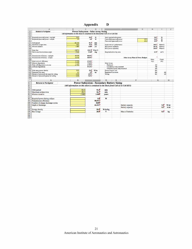
Since we have not yet decided on every component of the cubesat’s different subsystems, we cannot yet obtainan official amount of power needed from the cubesat during daylight or eclipse, nor can we properly determine ifour current configuration is adequate. A model was provided to us by the authors of the SMAD textbook, whichentails an intricate spreadsheet based on the above equations, amongst others, to adequately size the solar generationunit of the power system. A screenshot of the model can be seen in the Appendix D.
2. Preliminary CalculationsTable 12. Assumptions for Preliminary sizing calculations
In order to make preliminarycalculations, assumptions had to be Assumptions Worst Case Zero incidencemade for cell efficiency, inherent Cell efficiency 27% 27%degradation, degradation and
Input power [w/m^2] 1368 1368incidence angles. Two differentInherent degradation 0.77 0.77values of incidence angle were used.
Degradation 2.75% 2.75%The first was at zero incidence andIncidence angle [deg] 23 0the second was to see the effects
using a worst-case scenario oftwenty three degrees. The Table 13. Results for preliminary sizing
calculationsassumption values can beseen in Table 12. The values Zero
Differencefor efficiency were taken Results Worst Case incidencefrom the data sheet of the
Pout [w/m^2] 369.36 369.36 0TASC solar cells in AppendixPBOL [w/m^2] 261.8 284.41 7.95%A. The input power was
taken from the Space Mission LD 0.975 0.975 0Analysis and Design PEOL [w/m^2] 254.6 276.6 7.95%handbook. Inherent Area [m^2] N/A N/Adegradation and degradationwere both taken from theSMAD handbook as well.
The flowing table displays the results of those calculations using the SMAD model. The power output densitywas calculated, beginning of life power density, life degradation and end of life power density for both incidenceangles. Between both angles, there is only an eight percent difference between beginning of life and end of lifepower at zero and worst-case incidence angles.
However, at this point in time, the most important parameter is the required area of the solar cell and it cannot bedetermined. As it was pointed out in the previous section, the total output power of the solar array and required areais dependent upon the required power draw during eclipse and daylight. In order for this information to bedetermined, the final list of components and power budget needs to be decided upon.
B. Available EnergyThe production of energy of the cubesat relies on the area of solar cells, the efficiency of the solar cells, the sun’s
radiation intensity and the incidence angle at which the sunlight strikes the cells.
= ! ∗ ∗ (19)
Where ! is the intensity of solar radiation, is the effective area of the solar cells and is the efficiency of the solar cells.
14American Institute of Aeronautics and Astronautics

1. Angle of incidenceThe angle of incidence, , is the angle at which sunlight strikes a particular surface of the satellite. It is measured
from normal incidence at zero degrees, to perpendicular incidence at 90 degrees. Area is a function of the angle ofincidence.
= ! ∗ cos ( ) (20)
! is the area of solar cells on one side of the satellite. At zero degrees of incidence, the sunlight
Figure 10. Solar radiation, incidenceangle and Figure 11. Effective area vs.
Incidence angle.effective area.
reaches the highest potential effectivearea. As the angle of incidence increasesaway from the perpendicular, a smallereffective area is available.
Figure 12 displays the relationshipbetween effective area of solar cells onone face of the cubesat and the incidenceangle at which the sunlight strikes thesurface. The effective area of the cubesat was chosento be 0.036 !. It can be seen that the effective area isindirectly proportional to the incidence angle. A higherincidence angle results in a lower amount of effectivearea.
2. Preliminary CalculationsUsing the efficiency of the TASC
solar cells, the total available solar cellarea calculated in the solar panel sizingsection, and the solar radiation intensityprovided by SMAD, we can see therelationship between energy produced,incidence angle and effective area. It can
Figure 12. Power production vs. Effective area and incidence angle.
be seen that energy production is directly proportional to the effective area and indirectly proportional to theincidence angle.
The efficiency of the solar cell, , is a nominal value given by manufacturers in data sheets. However, this efficiency is also a functionof incidence angle as well, ( ). For preliminary calculations, it is adequate to assume a nominal efficiency for solar cells. However,more theory is needed in order to obtain transmission coefficients and properly account for rotation of the satellite over time. Themaximum output power at zero incidence and maximum effective area was calculated to be 13.45W.
15American Institute of Aeronautics and Astronautics

VII. Future Work
Final system components for the spacecraft bus need to be decided upon in order adequately size and design thepower generation unit of the cubesat. At this point in time, the final components and design of the attitude controlsystem has yet to be determined as well. Once these choices are made, we will determine if our current design meetsthe battery discharge requirements of the power storage unit as well as properly supply energy to the spacecraft bus.This will be accomplished by using the SMAD model. A larger selection of solar cells will also be investigated.Once the power generation unit is properly sized, the printed circuit board will need to be designed. This will beachieved through use of free, open source CAD software. The solar panels will then be tested to ensure that theymeet the specifications provided by the manufacturer’s datasheets as well as to observe their functionality with therest of the spacecraft bus. The power control board will then be designed in order to properly distribute powerthrough the spacecraft bus.
References[1] Ali, A., Mughal, M.R., Ali, H., "Innovative power management, attitude determination and control tile for
CubeSat standard NanoSatellites," Acta Astronautica, Vol. 96, No. 0, 2014, pp. 116-127.
[2] "BCT." BCT. Blue Canyon Technology, 2013. Web. 26 Feb. 2015. <http://bluecanyontech.com/all_products/cubesats/>.
[3] Brown, C.D., and ebrary, I., "Elements of spacecraft design," AIAA education series, American Institute of Aeronautics and Astronautics, Inc., Reston, Va., 2002, pp. 606.
[4] Clark, C., and Mazarias, L., “Power System Challenges For Small Satellite Missions,” Clyde Space Ltd., 6.01 Kelvon Campus, Scotland, 2006.
[5] Erlank, A., Steyn., “Arcminute Attitude Estimation for CubeSats with a Novel Nano Star Tracker,” International Federation of Automatic Control, Stellenbosch University, South Africa, 2014.
[6] Hapgood, Mike. "Space Weather: Its Impact On Earth and Implications For Business." Lloyd's. RAL Space,2010. Web. 22 Feb. 2015. <http://www.lloyds.com/~/media/lloyds/reports/360/360%20space%20weather/7311_lloyds_360_space%20weather _03.pdf>.
[7] Ian, Poole. "Radio Waves and the Ionosphere." Nature 154.3909 (1944): 413. Staines TW18 2PW, Nov. 1999. Web. 2 Feb. 2015.
[8] Kai-Rang, W., Jun, L., Lian-Guang, L., "A Statistical Study on the Geomagnetically Induced Current EventsDriven by Earth-directed Full-Halo Coronal Mass Ejections," Chinese Astronomy and Astrophysics, Vol. 36, No. 3,2012, pp. 261-281.
[9] Mansour, Nagi, and Jeremie Meurisse. "The Potential of CubeSats for Space Weather Applications." (2014):n. pag. Research Gate. Web. 2 Feb. 2015.<http://www.researchgate.net/profile/Meurisse_Jeremie/publication/266852705_The_potential_of_CubeSats_for_space_weather_applications/links/543d47250cf25d6b1ad74a50.pdf.>.
[10] Navarathinam, N., Lee, R., and Chesser, H., "Characterization of Lithium-Polymer batteries for CubeSat applications," Acta Astronautica, Vol. 68, No. 11–12, 2011, pp. 1752-1760.
[11] "Small Spacecraft Technology State of the Art." Spacecraft 47.2 (2014): 150-58. Nasa.gov. Mission DesignDivision Staff, July 2014. Web. Feb. 2015.<http://www.nasa.gov/sites/default/files/files/Small_Spacecraft_Technology_State_of_the_Art_2014.pdf>.
[12] United States, "Code of federal regulations," National Archives and Records Administration, Washington, D.C., 199u,
16American Institute of Aeronautics and Astronautics

[13] Viscio, M.A., Viola, N., Corpino, S., "Interplanetary CubeSats system for space weather evaluations and technology demonstration," Acta Astronautica, Vol. 104, No. 2, 2014, pp. 516-525.
[14] Xie, Ning. "A Miniaturized Micro-Digital Sun Sensor by Means of Low-Power Low-Noise CMOS Imager."IEEE SENSORS JOURNAL 14.1 (2014): n. pag. IEEE Xplore. IEEE. Web. Feb. 2015.<http://ieeexplore.ieee.org/stamp/stamp.jsp?arnumber=6588567>.
[15] C. Passerone, M. Tranchero, S. Speretta, L. Reyneri, C. Sansoe, D. Del Corso, Design solutions for auniversity Nano-satellite, in: Proceed- ings of the Aerospace Conference, 2008 IEEE, vol. no., 1–8 March 2008, pp.1, 13.
[16] Curtis, H., "Orbital Mechanics for Engineering Students," Aerospace Engineering, Elsevier Science, Burlington, 2009, pp. 740.
[17] Seeber, G., and ebrary, I., "Satellite geodesy," Walter de Gruyter, Berlin; New York, 2003, pp. 589.
[18] Wertz, J.R., and Larson, W.J., "Space mission analysis and design," Space technology library, Kluwer Academic, Dordrecht, Netherlands; Boston, 1991, pp. 811.
[19] CubeSat Design Specification Rev. 12,The CubeSat Program, Cal Poly SLO
17American Institute of Aeronautics and Astronautics

Appendix A
18American Institute of Aeronautics and Astronautics

Appendix B
19American Institute of Aeronautics and Astronautics

Appendix C
20American Institute of Aeronautics and Astronautics
Appendix D
21American Institute of Aeronautics and Astronautics