Embed Size (px)
Citation preview

THERMAL SPRAYED COATINGS (METALLIZATION) PROGRAM
December 12, 2017
North Carolina Department of Transportation Materials and Tests Unit
Structural Materials Group
Version 1.0
1 | P a g e

DOCUMENT CONTROL The THERMAL SPRAYED COATINGS (METALLIZATION) PROGRAM is reviewed during use for adequacy and updated as necessary by the NCDOT Structural Materials and Services Group. Electronic Portable Document Format (PDF) has been selected as the primary distribution format. The official version of the program is available on the NC Department of Transportation Website. Hard Copy Users who choose to print a copy of the manual are responsible for ensuring use of the most current version.
2 | P a g e

REVISION LOG Revision Date Description Approval By
3 | P a g e

Contents DOCUMENT CONTROL ............................................................................................................................................................ 2
REVISION LOG ......................................................................................................................................................................... 3
INTRODUCTION ....................................................................................................................................................................... 5
PURPOSE ............................................................................................................................................................................. 5
SCOPE .................................................................................................................................................................................. 5
GENERAL INFORMATION ........................................................................................................................................................ 5
1.0 PRE-QUALIFICATION ............................................................................................................................................... 6
2.0 REVOCATION OF QUALIFIED STATUS ...................................................................................................................... 7
3.0 NOTIFICATION OF WORK ........................................................................................................................................ 7
4.0 PRE-JOB MEETING ................................................................................................................................................... 7
5.0 SAFETY ..................................................................................................................................................................... 7
6.0 STORAGE AND HANDLING ...................................................................................................................................... 8
7.0 TSC MATERIALS ....................................................................................................................................................... 8
8.0 TSC PROCESS ........................................................................................................................................................... 9
9.0 SPECIFIC COATING APPLICATION .......................................................................................................................... 10
10.0 COATINGS INSPECTION ......................................................................................................................................... 13
11.0 ADHESION STRENGTH ........................................................................................................................................... 15
12.0 CUT TEST ............................................................................................................................................................... 15
13.0 DRY FILM THICKNESS ............................................................................................... Error! Bookmark not defined.
14.0 COATING REPAIR ................................................................................................................................................... 19
15.0 TWELVE-MONTH OBSERVATION PERIOD ............................................................................................................. 19
ATTACHMENT 1 ..................................................................................................................................................................... 20
ATTACHMENT 1.....…………………………………………………………………………………………………………………………………………………….. 19 ATTACHMENT 2……………………………………………………………………………………………………………………………………….………………… 20
4 | P a g e

INTRODUCTION
PURPOSE This program is provided to serve as a guide and source of reference for the NCDOT minimum requirements for shop performed surface preparation, the application of a thermally sprayed metallic coating (metallizing), the application of a seal coat, and touch up repairs.
Thermal sprayed coating (TSC) and sealer are applied to metal surfaces as specified herein when called for on the plans or by other Special Provisions, or when otherwise approved by the Engineer in accordance with the current edition of SSPC-CS 23.00/AWS C2.23/NACE No. 12 Specification. Only Arc Sprayed application methods are used to apply TSC coatings.
SCOPE The Program affects the fabrication facilities, coaters, NCDOT Materials office and consultants who are involved in the verification and other quality assurance inspection and testing of the steel and miscellaneous metal products.
GENERAL INFORMATION Materials shall be metallized and sealed in accordance with this Program, the Contract Special Provisions, latest edition of the current NCDOT Standard Specifications, latest edition of SSPC CS 23.00 and the manufacturer’s recommendations; of these the more stringent shall apply. Materials not meeting these requirements will be considered defective. The Engineer may reject all such materials, whether installed or not. Upon rejection remove non-conforming material from the site of the work or tag such material with the appropriate “HOLD” tag or equivalent as identified in the TSC facility Quality Control Manual until a corrective action plan has been submitted, approved and ready to implement.
1. QUALITY CONTROL INSPECTION PERSONNEL
All quality control (QC) personnel are subject to review and acceptance of the Engineer. The minimum certifications required shall be NACE CIP Level II or higher.
2. INSPECTION INSTRUMENTS
Unless more stringent requirements are specified by the manufacturer or stated in the TSC facility’s Quality Manual, calibration verification of instruments used for inspection is performed by the equipment manufacturer annually. The TSC facility maintains calibration records and certificates in the office for all instruments that require formal calibration. Calibration records shall be available for instruments being used by QC personnel on site. At a minimum, QC personnel shall use calibrated instruments as identified in their QC Manual and the equipment manufacturer’s recommendations as provided to the Department in the Prequalification section of these provisions. They shall conduct the required quality control tests in accordance with these requirements and report the minimum information required by the appropriate ASTM test methods and these provisions. See Table 1 for the required inspections. The minimum test equipment to be utilized in order to comply with Table 1 is listed below:
5 | P a g e

• Sling Psychrometer Bulb Type ASTM E-337 • Surface Temperature Thermometer • Tape Profile Tester - ASTM D-4417 Method C • Surface Condition Standards - SSPC VIS-1 and VIS-3 • Surface Contamination Analysis Kit or (Chloride Level Test Kit) SSPC Technology Guide 15
and/or SSPC TU4 NV2 • Wet Film Thickness Gage - ASTM D-4414 • Dry Film Thickness Gage - ASTM D-7091 and/or SSPC-PA2, Type 2 Electronic Gages • Adhesion Pull Test - ASTM D-4541 (Annex A3 and/or A4 for curved surfaces) • Chisel Test - As specified in this document
At the discretion of the TSC facility, electronic or other digital equipment may be utilized provided it has been pre-approved by the Department. 3. REPORTING
The operator shall provide coating inspection reports to the Department in accordance with the requirements of NCDOT Standard Specifications Section 442-13 and SSPC-CS-23.00.
1.0 PRE-QUALIFICATION
The minimum qualifications for a TSC facility to perform metallizing work for the Department are as follows:
• Shop facilities that are currently certified and in good standing with the American Institute Steel Construction (AISC) /Sophisticated Paint Endorsement (SPE) and/or the Society of Protective Coatings (SSPC) Qualification Procedure Three (QP-3).
• Shop facilities shall have and be in good standing with the SSPC QP-6 program when providing TSC materials for a marine environment. NCDOT defines marine environment as the oceans, seas, bays, estuaries and other major water bodies including their surface interface and interaction with the atmosphere and the land seaward of the mean high water mark, which are located in counties Division 1, 2 and 3 (see Attachment 2).
Shop facilities shall employ a NACE CIP Level III to oversee all QC functions. These personnel shall be responsible for all QC inspection and examination activities and upon completion, review and sign off on the final turnover package to be submitted for the project. Each TSC facility (shop) shall be pre-qualified before they are allowed to apply any metallized coating (regardless of square footage) for NCDOT projects. A list of approved facilities is provided under Facility Type: “Structural Steel Shop Metallizing Facility” at the following link: https://apps.ncdot.gov/vendor/approvedproducts/Producer.aspx
• Enclosed Shop: As per modified AISC/SSPC, an enclosed shop is a permanent facility or building (four continuous walls or partitions to grade or floor with a roof).
• The minimum requirements for shop prequalification are as follows: • Compliance with AISC and/or SSPC certification programs identified above. • 18 months of previous coating application experience on similar structures. • Review and approval of application equipment and coating material information. • Abrasives: Name of product, Manufacturer/Supplier, mesh size, cleanliness report, certification
of conformance to all requirements of SSPC AB1 and/or SSPC AB 3 as supplied by the abrasive supplier. Testing documentation of the recycled work mix as required by SSPC AB-2 prior to first use.
• Blasting and thermal spray equipment: Type and name of the Manufacturer/Supplier, to include voltage, and amperage settings.
• Spray Material: Name of Manufacturer/Supplier, wire size, chemical composition. 6 | P a g e

• Sealer: Name of product and Manufacturer/Supplier. • Review of the Quality Control plan to include QC responsible for oversight and inspection
activities, surface preparation, TSC application procedures, sealer application and coating repair procedure(s).
• Review and approval of material numbering/labeling/identification plan. • Review and approval of TSC supervisor and TSC operator qualification.
These requirements if more stringent, shall apply.
2.0 REVOCATION OF QUALIFIED STATUS Qualification of a shop facility may be revoked for a time as determined by the Engineer. The Engineer is defined in Article 101-3 of the Standard Specifications for Roads and Structures. Criteria for removal are as follows:
• Critical and major deficiencies as defined by the Engineer. • Failure to respond to the Engineer’s request for information. • Failure to correct continued non-conforming quality. A repetitive non-conforming item requires a
corrective action plan to be submitted and approved by the Engineer, implemented and monitored by the TSC facility.
• Failure to maintain the minimum qualifications for a TSC facility outlined in the Pre-Qualification section of this program.
• Failure to repair metallization that has been applied and approved by the TSC facility that exhibits any visible rust that cannot be removed by pressure washing.
3.0 NOTIFICATION OF WORK Prior to starting work, in-state TSC facilities shall provide a minimum of three (3) working days’ notice and out- of-state TSC facilities shall provide a minimum of eight (8) working days’ notice by submitting a notice of beginning work form (Attachment 1). When submitting the form (Attachment 1), the facility shall include work schedule, days per week, hours per day and number of shifts. Typical working hours are considered Monday through Friday (8am- 5pm). If the coater and/or fabricator are at the same location no additional notification is required. If the TSC facility does not perform scheduled work for a period exceeding three (3) consecutive days, additional notification of work as identified above shall be submitted. Any work performed without proper notification as identified above will be performed at the TSC facility’s risk. At the TSC facility’s option, reimbursement of the cost of the Department’s quality assurance inspection to facilitate varying work schedules may be requested. This shall be submitted to the Engineer in writing.
4.0 PRE-JOB MEETING The Department may require a pre-job meeting for specific applications as determined by the Engineer.
5.0 SAFETY Thermal spray coatings may involve the use of hazardous materials, operations, and equipment. This TSC Program does not address all of the potential safety concerns associated with their use. It is the responsibility of the TSC facility to establish appropriate safety and health requirements, and determine any regulatory requirements or limitations prior to use.
7 | P a g e
Personnel involved in the inspection and/or oversight of any TSC application should work directly with the TSC facility’s safety personnel to ensure proper safety protocol is being followed.
6.0 STORAGE AND HANDLING For all TSC components, the TSC facility shall take all necessary precautions to prevent any contamination and/or damage during handling, storage and transportation which include storing in the open air at any time during the TSC process (surface preparation through curing of seal coat). Do not expose the TSC consumables to rain, excessive condensation, long periods of direct sunlight, or temperatures above 110F or below 40F. In addition, the TSC facility shall place a device which records the high, low and current temperatures inside the storage location which houses the TSC consumables. Follow the manufacturer’s storage requirements if more restrictive than the above requirements. Coating material shall arrive at the TSC facility in sealed containers clearly marked with the type, batch and/or lot numbers properly labeled on the container. There shall be no modification of the coating except upon and in accordance with the express written stipulation by an authorized representative of the coating manufacturer and with specific approval of the Engineer. At the Department’s option, the inspector may randomly collect a sample of the coating used on the project if the material has been exposed to extremely high/low temperatures and/or exhibits excessive skinning in the container. For field applications the TSC facility shall take all necessary precautions to protect the TSC products from damage during handling and storage.
7.0 TSC MATERIALS Provide TSC wire in accordance with the metallizing equipment manufacturer’s recommendations. Use the wire alloy specified on the plans and which meets the requirements of AWS C2.25 and/or ASTM B833 Standard whichever is more stringent. The TSC facility shall provide a certified analysis (NCDOT Type 2 Certification) for each lot of wire material received. The TSC facility shall provide the Engineer with a twelve-inch (12”) sample of each lot/batch number of wire used. This sample will be used to verify wire chemistry. Use sealers provided by Coating Manufactures that are listed on the NCDOT Approved Products Listing. A complete list of approved products may be found on the NCDOT Approved Products Listing at: https://apps.dot.state.nc.us/vendor/approvedproducts/. Under Product Group, select “Paints”, under Product Category, select “Sealers” and/or “Epoxy Mastic”. TSC sealers are low-viscosity, clear or colored (pigmented as approved by the Engineer) products formulated to flow over and be absorbed into the natural pores of the TSC. The pigment particle size for colored sealer must be small enough to flow easily into the pore of the TSC, nominally a 5-fineness of grind per ASTM D1210. Sealer coat material manufacturers shall provide recommendations for product thinning, certification that their sealer is compatible with the TSC and service environment. If TSC material is being used in an immersion environment, an approved mastic aluminum or equivalent shall be used. All material coatings applied shall be from the same manufacturer. Before any coatings are applied, the TSC facility shall provide the Engineer a copy of the product data sheet, SDS (formerly MSDS) sheet, manufacturer’s certification and NCDOT HICAMS test report for each type, color and/or batch of coating used on the project.
8 | P a g e

8.0 TSC PROCESS 1. Job Reference Standard
Prior to starting surface preparation the TSC facility shall provide a Job Reference Standard (JRS) in accordance with SSPC CS-23.00. The JRS shall be an accurate representation of the end product. Any changes or modifications in how the JRS was prepared, coated and/or sealed shall require a new JRS. This standard shall be maintained at the facility and accessible to the Department and all appropriate parties. The Department shall be given the opportunity to witness all phases of work necessary in the performance of the JRS.
1. Special Attention Structural members utilizing welded construction shall incorporate seal welding of these connections for any design that may be prone to staining, oxidation and/or rust bleed out after the completion of the TSC process. The TSC facility shall submit a plan to the Engineer prior to beginning work for structural members that are comprised of complex geometries and/or members (sheet piles) that may require additional assembly after the TSC process is complete to address continued staining, oxidation and/or rust bleed out.
2. Blasting Equipment
The compressed air shall be free of water and oil. Adequate separators and traps shall be provided, installed in the coolest part of the system.
For manually-operated blast equipment, the presence of oil and water shall be determined in accordance with ASTM D-4285 at least one (1) time per eight (8) hour shift and following every compressor start-up.
3. Surface Preparation
Surface preparation shall be in accordance with SSPC SP-5 (White Metal Blast) for metallized components going to the following counties:
DIVISION 1 COUNTIES DIVISION 2 COUNTIES DIVISION 3 COUNTIES Northampton, Gates, Bertie,
Martin, Washington, Tyrell, Dare, Hyde, Chowan, Perquimans,
Pasquotank, Camden, Currituck
Lenoir, Greene, Pitt, Beaufort, Craven, Jones, Pamlico, Carteret
Sampson, Duplin, Pender, Onslow, New Hanover, Brunswick
Surface preparation shall be in accordance with SSPC SP-10 (Near White Metal Blast) for the remaining counties in Divisions 4, 5, 6, 7, 8, 9, 10, 11, 12, 13 and 14 unless otherwise specified. Fabrication shall be complete before surface preparation begins. Weldments shall meet the following criteria prior to abrasive blasting:
• Grind all flame cut edges to remove carburization prior to blasting operations • Bevel corners to an approximate 1/16” chamfer if the included angle is less than 90 degrees
Weld or base metal discontinuities that do not meet the requirements of ASTM A6 and/or contract requirements that are discovered after surface preparation shall be repaired in accordance with ASTM A6. Any
9 | P a g e

deposition of weld metal required to correct surface imperfections described in ASTM A6 and/or that does meet the requirements of the contract shall be subject to approval by the Engineer.
If the material is being transported in adverse weather conditions, the TSC facility shall notify the Department. The Engineer may require the TSC facility to test for the presence of chlorides, and, if necessary, clean the material as directed by the Engineer.
QC shall record ambient conditions at the time of final blast cleaning and prior to metallizing. Do not perform blasting operations when the temperature of the steel surfaces is less than 5 degrees above the dew point of the surrounding air or the relative humidity of the air is greater than 85%.
The TSC facility shall not perform acid washes or use cleaning solvents or other chemical treatments on metal surfaces after they have been blast cleaned. The restriction includes, but is not limited to, inhibitive washes and partial TSC applications that are intended to prevent rusting. Any surface(s) on which mist coating, flash coating and/or chemical treatment is applied will be unacceptable and will require the entire part, piece or component to be re-blasted to the original blast cleanliness specification.
The maximum working interval between blasting of the steel surface and the completed TSC (with the exception of the sealer) shall be as follows:
• Eight (8) hours maximum when the relative humidity is < 60% • Seven (7) hours maximum when the relative humidity is < 70% • Six (6) hours maximum when the relative humidity is < 85% • There shall be no TSC application of product when the relative humidity is > 85%
If the working intervals identified above exceed the maximum specified and/or the dew point temperatures cannot be maintained, the surface cleanliness shall be verified by QC and quality assurance. If the surface cleanliness is not in conformance with the Contract Documents, non-conforming areas shall again be abrasive blasted in compliance with the Contract Documents. 4. Surface Profile
The surface profile shall be verified and documented in accordance with ASTM D-4417 and impart a 3.0 mil minimum angular profile. The average of readings obtained at each location (“location average”) shall be within the specified profile range. The inspection frequency for obtaining surface profile readings is as follows:
• A minimum of two surface profile readings per side of beam/girder, pile (H-pile, Sheet pile and/or Pipe pile)
• A minimum of four surface profile readings per 10% of surface area for materials not included above
9.0 SPECIFIC COATING APPLICATION 1. Operator Qualification Prior to coating application, perform bend tests on material prepared by each operator in accordance with SSPC CS 23.00, Appendix A (Bend Test). QC shall monitor, document, identify and maintain bend test coupons for review by Quality Assurance (QA) personnel. Documentation shall address the following:
• Electrical characteristics (current, amperage, voltage, wire feed speed and nozzle to work distance)
• Specified wire alloy 10 | P a g e
• Five coupons per operator for each shift
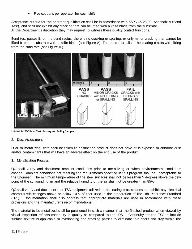
Acceptance criteria for the operator qualification shall be in accordance with SSPC CS 23.00, Appendix A (Bend Test), and shall not exhibit any cracking that can be lifted with a knife blade from the substrate. At the Department’s discretion they may request to witness these quality control functions. Bend test passes if, on the bend radius, there is no cracking or spalling, or only minor cracking that cannot be lifted from the substrate with a knife blade (see Figure A). The bend test fails if the coating cracks with lifting from the substrate (see Figure A.)
Figure A: TSC Bend Test: Passing and Failing Sample 2. Dust Assessment Prior to metallizing, care shall be taken to ensure the product does not have or is exposed to airborne dust and/or contaminants that will have an adverse effect on the end use of the product. 3. Metallization Process QC shall verify and document ambient conditions prior to metallizing or when environmental conditions change. Ambient conditions not meeting the requirements specified in this program shall be unacceptable to the Engineer. The minimum temperature of the steel surfaces shall not be less than 5 degrees above the dew point of the surrounding air and the relative humidity of the air shall not be greater than 85%. QC shall verify and document that TSC equipment utilized in the coating process does not exhibit any electrical characteristic changes above or below 10% of that used in the preparation of the Job Reference Standard (JRS). Documentation shall also address that appropriate materials are used in accordance with these provisions and the manufacturer’s recommendations. The material to be metallized shall be positioned in such a manner that the finished product when viewed by visual inspection reflects continuity in quality as compared to the JRS. Continuity for the TSC to include surface texture is applicable to overlapping and crossing passes to eliminate thin spots and stay within the
11 | P a g e

coating thickness specification. The material, when viewed by direct visual observation and with a 10X magnifier, shall not exhibit any gross porosity or detrimental discontinuities as compared to the JRS. While the Department recognizes that porosity in the aluminum TSC is of concern, special care shall be taken to minimize this anomaly as compared to the JRS. The operator shall pay particular attention to TSC application on bent radius, bolts, edges and welds. The operator shall apply the TSC to these areas maintaining a work angle perpendicular to the bend radius, bolts, edges or welds throughout the application process ensuring 100% coverage of these critical areas. Members with complex geometries shall be evaluated by the TSC facility for proper application and coverage. The operator shall apply a technique that will minimize a gross deviation of work angle that may result in unacceptable surface texture, excessive overspray, loss of coating adhesion, gross porosity and/or detrimental discontinuities as compared to the JRS. If rust bloom, blistering or a degraded coating appears at any time during thermal spraying, stop work and notify the QC for direction. Upon successful completion of the metallization process and prior to sealer application, the dry film thickness (DFT) shall meet the requirements of Table 2 or thickness specified on the plans. 4. Sealer Process QC shall record ambient conditions prior to sealer application or when environmental conditions change. Ambient conditions not meeting the requirements specified in this program shall be unacceptable to the Engineer. The minimum air/steel temperature shall be 40 degrees or higher. The steel temperature shall be a minimum of 5 degrees above the dew point temperature of the surrounding air. The relative humidity of the air shall not be greater than 85%. When noted on the plans or as specified in Table 2, apply the sealer to all metallized surfaces in accordance with the manufacturer’s recommendations and these provisions. The more stringent shall apply. Sealer application shall be applied as soon as possible after the TSC and before visible (10X magnification) oxidation of the TSC occurs. In no case shall the sealer be applied after a period exceeding eight (8) hours. If the sealer is not applied within eight (8) hours, the surface preparation outlined above in this program shall apply. If excessive dry spray or overspray is present on the metallized surface, perform additional conditioning in the form of hand tool cleaning prior to sealer application. If moisture is present in the TSC pores, the steel shall be heated to not more than 250 degrees to remove moisture prior to the sealer application. When possible heat the steel from the reverse side of the TSC to minimize oxidation and contamination of the TSC prior to sealing. (ANSI/AWS C2.18-93R) Sealer application shall be performed by spraying with the exception of small repairs that are less than one square foot. In this case the TSC facility may use a brush or roller. Use enclosures that control atmospheric conditions inside within limits suitable for coating and until the sealer has cured in accordance with the manufacturer’s recommendations sufficiently to re-coat, obtain DFT readings and/or withstand environmental conditions that may result in the sealer coat being contaminated. 12 | P a g e

10.0 COATINGS INSPECTION QC is required to record and maintain inspections that are specified by the contract and in accordance with the current Standard Specifications, ensuring that they are signed by the QC inspector who performed the inspection. The shop facilities NACE CIP Level III shall periodically review and sign QC personnel inspection reports. These records shall be available at the shop for review and submitted to the Quality Assurance representative at the end of each work week or as directed.
At a minimum the quality control forms shall be on company letterhead with logo that provides a daily inspection report form equivalent to the information required on M&T-610. Submit all Dry Film Thickness (DFT) readings on a form equivalent to M&T-611 to include sealer application. Digital versions of these forms can be found on the NCDOT Materials and Tests webpage: https://connect.ncdot.gov/resources/Materials/Pages/ChemicalLaboratory.aspx The quality control inspections as outlined in Table 1 below shall be performed.
13 | P a g e

Table 1 Required
Inspection Test
Standard Location Frequency Specifications
Ambient Conditions
ASTM E-337 At the location where the work is being
performed
Prior to final abrasive blast cleaning, prior to
TSC application, prior to sealer application
and/or as conditions change
ASTM E-337
Abrasive Properties SSPC AB-1, SSPC AB-2
and/or SSPC AB-3
Prior to first use SSPC AB-1 SSPC AB-2 SSPC AB-3
SSPC AB-1 SSPC AB-2 SSPC AB-3
Surface Cleanliness SSPC SP-5 and/or SSPC
SP-10
All TSC surfaces Visual verification of all surfaces
SSPC SP-5- Immersion Service
SSPC SP-10- Atmospheric Service
Job Reference Standard
SSPC CS 23.00
TSC facility One per job Meets all requirements listed
in Table 2 specific to wire alloy.
Operator Bend Test
SSPC CS 23.00
TSC facility Five coupons per operator for each shift.
SSPC CS.23.00
Surface Profile ASTM D-4417 Method C
Random surfaces A minimum of two surface profile readings
per sides of beam/girder, pile (H-pile, Sheet pile and/or
Pipe pile).
A minimum of four surface profile readings per 10% of materials not included above.
3.0 mils minimum
TSC Dry Film Thickness
SSPC PA-2 Each TSC surface Table 2 and Figures 1-4 SSPC PA-2
Sealer Dry Film Thickness
SSPC PA-2 Each TSC surface Table 2 and Figures 1-4 SSPC PA-2
Adhesion ASTM D-4541 Annex A3
and/or A4 for curved
surfaces
Random surfaces Once on the prepared surface, with a
minimum of one test per shift and per lot
99.9 Zinc >500 PSI 85%/15%
Zinc/Aluminum > 700 PSI
99.9 Aluminum >1,000 PSI
Cut Test SSPC CS 23.00
Random surfaces 5 sets per 500 ft2 or a minimum of 1 test per
shift per lot
No peeling or delamination
14 | P a g e

The Department may perform additional quality assurance inspection as deemed necessary by the Engineer to ensure that these contract provisions are being met.
1. Final Visual Inspection Acceptance Criteria
Visual examination using line of sight vision of surface preparation or coating inspection shall be done at an angle not less than 30 degrees and at a distance of no more than 24 inches. Ambient lighting as measured at the inspection surface shall not be less than 50 foot candles. Any surface contamination of the end product as a result of improper storage and/or protection as defined by the Engineer shall be removed by TSC facility prior to final acceptance by the Department.
11.0 ADHESION STRENGTH Prior to applying the sealer coat, the adhesion strength between the thermal spray coating and steel substrate shall be measured in accordance with ASTM D-4541. This is accomplished by applying the dollies on TSC surface prior to applying the sealer coat. After completion of the adhesion testing, affected surfaces shall be repaired. Provide repair procedures that are pre-approved by the Department and address adhesion and cohesion failures in the TSC substrate and/or sealer layer. One test equals 3 dollies in which the TSC facility shall properly taper and touch up all repair areas in accordance with SSPC PA-1, Section 10. If there is a failure associated with any one test an additional test is required. If additional failures occur, the TSC facility shall document the location and type of failure and provide the Department with a corrective action plan for review and approval. Adhesion tests shall be performed at least once on the prepared surface, with a minimum of one test per shift and per lot. A lot shall be defined as follows:
• A lot is one or more articles of the same type and size comprising a single order or a single delivery load, whichever is the smaller, or any number of articles identified as a lot by the TSC facility, when these have been metallized within a single production shift and in the same production area
12.0 CUT TEST Prior to applying the sealer coat, the cut test shall be performed in accordance with SSPC CS 23.00, Appendix B on random surfaces with 5 sets per 500 ft2 or a minimum of 1 test per shift per lot identified above. The cut test is accomplished by using the following minimum equipment or equivalent:
• One three (3) pound hammer with an eight and half inch (8 ½”) long handle • One seven inch (7”) long chisel with a one and one half inch (1 ½”) long shaft • One sixty (60) degree template
1. Testing Procedure
• Set the chisel on the surface to be tested and angle the shaft at approximately 60 degrees
to the surface with the beveled cutting edge to the outside of the angle. • Grasping the hammer at the end of the handle, gently position the hammer head on the
chisel head. • Once the head has been positioned, only the movement of the wrist from flex to extend is
used to deliver the hammer blow to the chisel.
15 | P a g e

• Impact the chisel with one blow at three separate areas 0.5 - 1.0 inches apart in a parallel line.
Observe the impact marks on the coated surface and determine if the test passes or fails based on the following criteria:
• PASS - No coating is disbonded in any of the three impact areas; there is only a 1.5" mark
the width of the cutting edge on the surface. • INCONCLUSIVE - The coating is disbonded or slides in one of the impact areas while the
other impact areas have no disbonded coating. • FAIL- Three marks exhibit disbonding or sliding.
If there is a failure associated with any one test an additional test is required. If additional failures occur, the TSC facility shall document the location and type of failure and provide the Department with a corrective action plan for review and approval.
13.0 DRY FILM THICKNESS
Dry film thickness measurements are mandatory for the QC and quality assurance inspectors on the TSC, sealer coat, barrier coat and/or top coat as applicable. Measurements shall be taken with a Type 2 gage as defined in SSPC PA-2, recorded to the frequency specified in this program and on a form similar to the M&T Form 611. The Type 2 gage needs to be adjusted to account for the profile of the substrate in order to read the thickness directly. Reserve a portion of the substrate after blast cleaning and prior to coating to adjust the gage. Alternatively, an uncoated test panel prepared in accordance with the surface preparation requirements herein may be used in lieu of the actual material subjected to the TSC process. The alternative method allowed above shall include material with similar magnetic properties and geometry as the substrate to be measured. The use of smooth steel substrates, to include calibration standards, are strictly prohibited for the use of gage adjustment. QC and quality assurance shall measure and record the dry film thickness (DFT) for the TSC and seal coat applications for those products identified in Figures 1, 2, 3 and 4 as applicable for that specific product. These requirements are applicable to each individual component and shall be obtained as identified in the appropriate Figures 1 through 4 below. Random locations are defined as equally spaced inspection intervals along the entire length of the member. All spot readings are defined as the average of 3 to 5 individual gage readings obtained within a 1 ½” diameter circle at each random location and must meet the minimum requirement specified. No additional tolerance (as allowed by SSPC PA-2) is permitted. Discard any single unusually high or low gage readings that are not repeated consistently. The average of the acceptable gage readings is the spot measurement. No spot average shall be less than that specified in Table 2 or as specified on the plans. For products not identified in Figures 1, 2, 3 and 4 the DFT inspection shall include each surface area, change in contour, face, leg, flange, edge and side for that member.
a. Sheet Pile Members
• 6 random locations for surface area identified above for members < 45 feet. (Figure 1) • For members greater than 45 feet in length, one additional location shall be required for
each additional 10 feet in length. 16 | P a g e

b. H & Steel Beam Members
• 8 random locations for surface area identified above for members < 45 feet. (Figure 2) • For members greater than 45 feet in length, one additional location shall be required
for each additional 10 feet in length.
c. Pipe Pile Members
• 8 random locations for surface area identified above for members < 45 feet in length and up to and including 24” in diameter. (Figure 3)
• For members greater than 45 feet in length and less than or equal to 24” in diameter, one additional location shall be required for each additional 10 feet in length.
• 12 random locations for surface area identified above for members < 45 feet in length for diameters greater than 24” and up to 48” in diameter. (Figure 4)
• For members greater than 45 feet in length and over 24” in diameter to 48” in diameter, one additional location shall be required for each additional 10 feet in length.
• For members greater than 48” in diameter, consult the Engineer for DFT testing interval.
d. Expansion Joints
• 8 random locations for surface area identified above for members < 45 feet in length
on both faces of the angle leg along the length of the expansion joint. • For members greater than 45 feet in length one additional location shall be required
for each additional 10 feet in length.
e. Bearing Assemblies
• For each bearing assembly, 5 random location areas per bearing face, in addition to measure 3 spot areas on each plate edges when greater than one inch in thickness.
f. Diaphragm/Cross-Frames/X and/or K Frame Assembly
• For each assembly that is < 5 feet in length, 5 random locations that encompass the entire assembly shall be examined. For assemblies greater than 5 feet in length, one additional location shall be required for each additional 12” in length.
When a spot reading is non-conforming, the extent of the non-conforming area will be determined by taking additional spot readings not to exceed a one-foot interval in all directions until acceptable spot averages are obtained. Material that does not meet the minimum DFT shall be demarcated using a non-staining material and documented. The operator shall repair these deficient areas in accordance with their pre-approved procedure.
17 | P a g e

Figure 1
A1
A2 A3
A4 A5
A6
A1
A2
A3
A4
A5
A6
A7
A8
Figure 3 12”-24” Pipe
A1
A8
Figure 2
A7
A2
A6 A4
A5
A3
Figure 4 24”-48” Pipe
A1
A3
A2
A8
A9
A11
A12
A4 A10
A7
A6
A5
18 | P a g e

Table 2
TSC Alloy TSC Aluminum
TSC Application Alloy Seal Coat*
99.9% Aluminum 10-15 mils DFT All other components not listed in Table 2 and that will be used in Divisions
1, 2 & 3
1.5 mils DFT
85% Zinc / 15% Aluminum
10-15 mils DFT Pot Bearings & Optional Disc Bearings
1.5 mils DFT
99.9% Zinc 10-15 mils DFT All other components not listed in Table 2 and that will be used in Divisions 4, 5, 6, 7, 8, 9, 10, 11,
12, 13 & 14
1.5 mils DFT
* Manufacturer’s recommendation shall be reviewed and the more stringent shall apply. The seal coat will be measured above the peaks of the TSC.
14.0 COATING REPAIR Routine repairs are defined as a single localized area measuring one square foot or less. The Engineer shall be consulted for non-localized and/or multiple areas of repair. All repairs that are performed must meet the requirements of this paragraph. The TSC facility shall provide a coating repair procedure to the Engineer prior to starting any surface preparation. The repair procedure shall demonstrate that the proposed work method and equipment used for the repair will meet the quality requirements listed in this program. Repair procedures are subject to the approval of the Engineer. If the thermal spray coating has been damaged and bare substrate metal is observed, the coating shall be repaired, including the local repair application of a new sealer. If the TSC facility did not exhibit reasonable conformance to protect the work during application, storage and/or construction, the Engineer may require a finish coat at no additional cost to the Department. The final acceptances of all repairs, to include aesthetics, will be approved at the Engineer’s discretion. The repair procedure shall meet all provisions of this document.
15.0 TWELVE-MONTH OBSERVATION PERIOD All TSC materials applied under the Thermal Sprayed Coatings (Metallization) Program shall be evaluated twelve (12) months after project acceptance for defective materials and workmanship. All repairs identified by the Engineer shall be made at no additional cost to the Department.
19 | P a g e

ATTACHMENT 1
Notification of Beginning Work Form
Date of Notification Name & Phone Number of Producer/Coater Contact Person
Planned Date to Start Work (see note at bottom of page) Name of Producer/Coating Contractor
Location of Producer/Coating Contractor Project Number
Contract Number County
Bridge Number Shop Job Number
Details of Work to Begin
Completed form should be submitted to the Metals Engineer, Welding Engineer & Coating Engineer (electronically or by mail) at:
Randy Porter Metals Engineer
NCDOT Materials and Tests Unit 1563 Mail Service Center
Raleigh, NC 27699 [email protected]
Eddie Shelar Welding Engineer
NCDOT Materials and Tests Unit 1350 Jammie Court
Winston Salem, NC 27106 [email protected]
Aaron Dacey Coating Engineer
NCDOT Materials and Tests Unit 1563 Mail Service Center
Raleigh, NC 27699 [email protected]
NOTE: According to Article 1072-7(A), the Materials & Tests Unit requires 72 hours (3 days) notice for in-state producers and 192 hours (8 days) notice for producers out-of-state producers.
NORTH CAROLINA DEPARTMENT OF TRANSPORTATION MATERIALS AND TESTS UNIT, STRUCTURAL MATERIALS GROUP
20 | P a g e

ATTACHMENT 2
21 | P a g e