Embed Size (px)
Citation preview

Thermal spray equipment guide
Issue 13 – May 2017
BRO-0002.13 – Thermal Spray Equipment Guide – May 2017 2
Optimum materials…
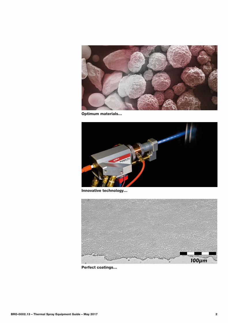
Innovative technology…
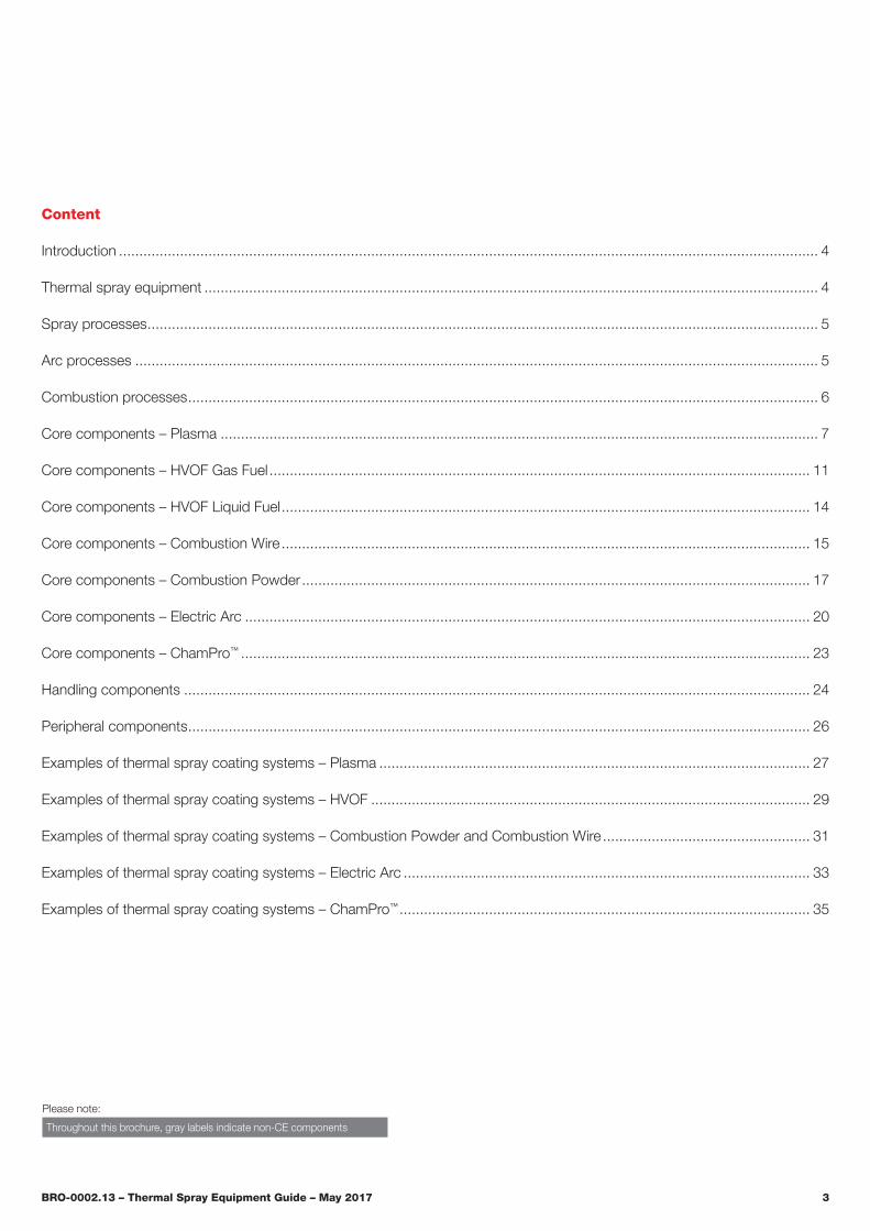
Perfect coatings…
BRO-0002.13 – Thermal Spray Equipment Guide – May 2017 3
Please note:
Throughout this brochure, gray labels indicate non-CE components
Content
Introduction ���������������������������������������������������������������������������������������������������������������������������������������������������������������������������� 4
Thermal spray equipment ������������������������������������������������������������������������������������������������������������������������������������������������������� 4
Spray processes ��������������������������������������������������������������������������������������������������������������������������������������������������������������������� 5
Arc processes ������������������������������������������������������������������������������������������������������������������������������������������������������������������������ 5
Combustion processes ����������������������������������������������������������������������������������������������������������������������������������������������������������� 6
Core components – Plasma ��������������������������������������������������������������������������������������������������������������������������������������������������� 7
Core components – HVOF Gas Fuel ������������������������������������������������������������������������������������������������������������������������������������� 11
Core components – HVOF Liquid Fuel ���������������������������������������������������������������������������������������������������������������������������������� 14
Core components – Combustion Wire ���������������������������������������������������������������������������������������������������������������������������������� 15
Core components – Combustion Powder ����������������������������������������������������������������������������������������������������������������������������� 17
Core components – Electric Arc ������������������������������������������������������������������������������������������������������������������������������������������� 20
Core components – ChamPro™ �������������������������������������������������������������������������������������������������������������������������������������������� 23
Handling components ���������������������������������������������������������������������������������������������������������������������������������������������������������� 24
Peripheral components ��������������������������������������������������������������������������������������������������������������������������������������������������������� 26
Examples of thermal spray coating systems – Plasma ���������������������������������������������������������������������������������������������������������� 27
Examples of thermal spray coating systems – HVOF ������������������������������������������������������������������������������������������������������������ 29
Examples of thermal spray coating systems – Combustion Powder and Combustion Wire ��������������������������������������������������� 31
Examples of thermal spray coating systems – Electric Arc ���������������������������������������������������������������������������������������������������� 33
Examples of thermal spray coating systems – ChamPro™ ����������������������������������������������������������������������������������������������������� 35
BRO-0002.13 – Thermal Spray Equipment Guide – May 2017 4
Thermal spray equipmentOnly Oerlikon Metco can offer equipment solutions for all thermal spray processes. And with such a broad selection, we have just what you need for your application. Proven and reliable, Oerlikon Metco has the largest base of installed equipment around the world.
Our focus is on our customer’s specific need. Through on-site analysis and customer consultation, our Engineering teams design coating application systems that combine ad-vanced technologies with the broadest line of thermal spray coating products available; that includes advanced robotics and microprocessor controls. The result is the most produc-tive and cost-effective solution for virtually any coating appli-cation and budget�
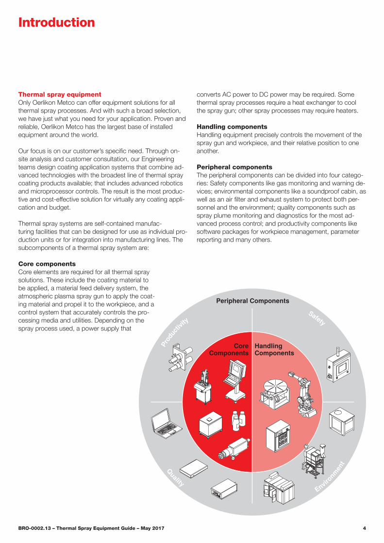
Thermal spray systems are self-contained manufac- turing facilities that can be designed for use as individual pro-duction units or for integration into manufacturing lines. The subcomponents of a thermal spray system are:
Core componentsCore elements are required for all thermal spray solutions. These include the coating material to be applied, a material feed delivery system, the atmospheric plasma spray gun to apply the coat-ing material and propel it to the workpiece, and a control system that accurately controls the pro-cessing media and utilities. Depending on the spray process used, a power supply that
converts AC power to DC power may be required. Some thermal spray processes require a heat exchanger to cool the spray gun; other spray processes may require heaters.
Handling componentsHandling equipment precisely controls the movement of the spray gun and workpiece, and their relative position to one another�
Peripheral componentsThe peripheral components can be divided into four catego-ries: Safety components like gas monitoring and warning de-vices; environmental components like a soundproof cabin, as well as an air filter and exhaust system to protect both per-sonnel and the environment; quality components such as spray plume monitoring and diagnostics for the most ad-vanced process control; and productivity components like software packages for workpiece management, parameter reporting and many others.
Introduction
Prod
uctiv
itySafety
Environmen
t
Quality
Peripheral Components
CoreComponents
HandlingComponents

BRO-0002.13 – Thermal Spray Equipment Guide – May 2017 5
Spray processesOerlikon Metco’s comprehensive portfolio of equipment assures we can deliver systems for every thermal spray application and budget requirement.
Electric arc wire sprayElectric arc wire spray uses two electrically charged feed-stock wires, of opposite polarity, that are brought together at a controlled rate to form an arc. This arc melts the wire feed-stock and an air stream propels the molten material to the substrate. Electric arc wire is commonly used to apply bond coat materials, salvage and restoration coatings and a wide range of corrosion coatings on large structures. As the cool-est of all thermal spray processes, it can be used to coat many substrates, including metals and plastics.
Atmospheric plasma sprayAtmospheric plasma spray is the most versatile of all thermal spray processes. Using an electric arc to ionize flowing pro-cess gases, the hot gas stream can be controlled to melt a very wide range of powder feedstock materials to apply high-quality coatings of metals, metallic alloys, carbides, cer-mets and oxide ceramics. Atmospheric plasma spray coat-ings are used for many different applications, just a few of which include bond coats, corrosion coatings for many
different service environments and temperatures, wear coat-ings, restoration coatings, and thermal barrier materials.
ChamPro™ controlled atmosphere sprayChamPro refers to plasma spray or electric arc wire spray coatings applied in a chamber at low pressure or near vacu-um conditions. ChamPro processes apply superior coatings characterized by high densities or very controlled porosities with extremely low contamination. Systems can be designed for many applications, including the application of refractory metals, thin layers and ceramic structures that cannot be achieved using any other thermal spray process.
Spray Processes
Arc Processes
Electric ArcWire Spray
ChamPro™
Atmospheric Plasma Spray
High VelocityOxy-Fuel Spray
(HVOF)
Combustion Spray
Combustion Powder Spray
Gas FuelHVOF
Combustion Wire Spray
Liquid FuelHVOF
Combustion Processes
Arc processes
Introduction
BRO-0002.13 – Thermal Spray Equipment Guide – May 2017 6
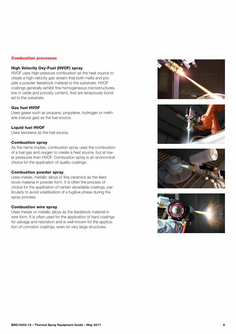
Combustion processes
High Velocity Oxy-Fuel (HVOF) sprayHVOF uses high-pressure combustion as the heat source to create a high-velocity gas stream that both melts and pro-pels a powder feedstock material to the substrate. HVOF coatings generally exhibit fine homogeneous microstructures, low in oxide and porosity content, that are tenaciously bond-ed to the substrate� Gas fuel HVOFUses gases such as propane, propylene, hydrogen or meth-ane (natural gas) as the fuel source.
Liquid fuel HVOF Uses kerosene as the fuel source.
Combustion sprayAs the name implies, combustion spray uses the combustion of a fuel gas and oxygen to create a heat source, but at low-er pressures than HVOF. Combustion spray is an economical choice for the application of quality coatings.
Combustion powder sprayUses metals, metallic alloys or fine ceramics as the feed stock material in powder form. It is often the process of choice for the application of certain abradable coatings, par-ticularly to avoid volatilization of a fugitive phase during the spray process.
Combustion wire sprayUses metals or metallic alloys as the feedstock material in wire form. It is often used for the application of hard coatings for salvage and retoration and is well-known for the applica-tion of corrosion coatings, even on very large structures.

BRO-0002.13 – Thermal Spray Equipment Guide – May 2017 7
SM-F220 SM-F300SM-F210SM-F100 CONNEXSM-F1
Core components – Plasma
Compatibility chart
Thermal spray equipment
Spray Gun
Power output 25 kW 20 kW 15 kW 16 kW 9 kW
Minimum internal diameter
80 mm (3.1 in) 100 mm (4 in) 60 mm (2.4 in) 85 mm (3.3 in) 40 mm (1.6 in)
Plasma gas Ar, H2, He
Connection angle 3 180° 90° / 180° 90° 180° 180°
Spray angle 4 90° / 45° 180° / 90° / 45° 90° / 20° 90° 90°
Spray length 500 mm (19.6 in)
140 / 280 / 560 mm (5.5 / 11 / 22 in)
250 / 450 / 650 mm (9.8 / 17.7 / 25.6 in)
287 mm (11.3 in)
250 / 450 mm (9.8 / 17.7 in)
Controller
JAMBox
Material Feeder
Power Supply
Gas Management Center
1
5
1 Spray length 50 mm (2 in) for external coating applications; limited functionality with UniCoatPro Plasma
2 Not compatible with UniCoatPro Plasma3 Connection angle is the angle between supply hoses and gun axis4 Spray angle is the angle between spray plume and gun axis
5 JAM-1020 used with MultiCoat and PT-type power source JAM-1030 used with MultiCoat and PT3X-type power source
6 Interface box required to operate UniCoatPro Plasma with 5MP and 9MP se-ries feeders; UniCoatPro Plasma provides powder on/off functionality
2
MultiCoatUniCoatPro Plasma
JAM-1020
JAM-1030JAM-1040
Single-120-ATwin-120-ASingle-220-A
Twin-140
Twin-1505MPE
9MP
9MPE
9MPE-CL20
9MP-CL20
PT3X IPS-500 PT3X IPS-1000 PT-Type
GMC Plasma
6 6
2
BRO-0002.13 – Thermal Spray Equipment Guide – May 2017 8
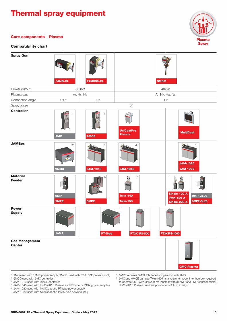
Core components – Plasma
Compatibility chart
1 9MC used with 10MR power supply; 9MCE used with PT-1110E power supply2 9MCD used with 9MC controller 3 JAM-1010 used with 9MCE controller4 JAM-1040 used with UniCoatPro Plasma and PT-type or PT3X power supplies5 JAM-1020 used with MultiCoat and PT-type power supply
JAM-1030 used with MultiCoat and PT3X-type power supply
6 5MPE requires 5MPA Interface for operation with 9MC 7 9MC and 9MCE can use Twin-150 in stand-alone mode; interface box required
to operate 9MP with UniCoatPro Plasma; with all 5MP and 9MP series feeders; UniCoatPro Plasma provides powder on/off functionality
Thermal spray equipment
Spray Gun
Power output 55 kW 40kW
Plasma gas Ar, H2, He Ar, H2, He, N2
Connection angle 180° 90° 90°
Spray angle 0°
Controller
JAMBox
Material Feeder
Power Supply
Gas Management Center
9MC 9MCE MultiCoat
UniCoatPro Plasma
JAM-10109MCD
5MPE
9MP
9MPE
9MP-CL20
9MPE-CL20
Single-120-ATwin-120-ASingle-220-A
JAM-1020
JAM-1030JAM-1040
GMC Plasma
10MR PT-Type PT3X IPS-500 PT3X IPS-1000
11
2 43 5
6
3MBM
Twin-140
Twin-150
F4MB90-XLF4MB-XL
7
BRO-0002.13 – Thermal Spray Equipment Guide – May 2017 9
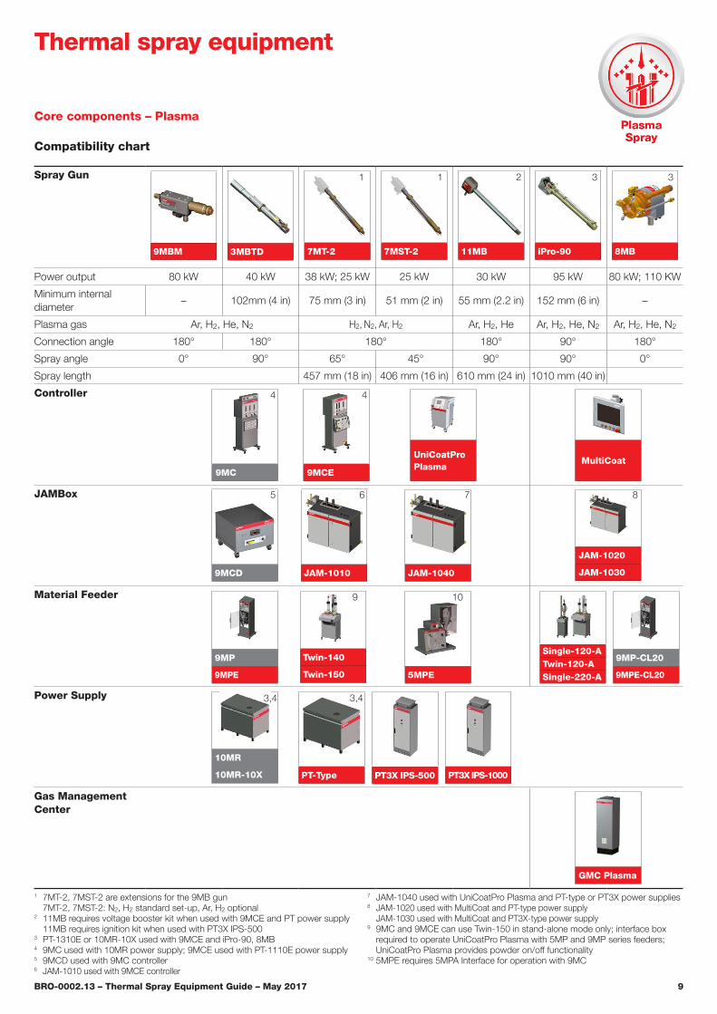
Core components – Plasma
Compatibility chart
Spray Gun
9MBM 3MBTD 7MT-2 7MST-2 11MB iPro-90 8MB
Power output 80 kW 40 kW 38 kW; 25 kW 25 kW 30 kW 95 kW 80 kW; 110 KW
Minimum internal diameter
– 102mm (4 in) 75 mm (3 in) 51 mm (2 in) 55 mm (2.2 in) 152 mm (6 in) –
Plasma gas Ar, H2, He, N2 H2, N2, Ar, H2 Ar, H2, He Ar, H2, He, N2 Ar, H2, He, N2
Connection angle 180° 180° 180° 180° 90° 180°
Spray angle 0° 90° 65° 45° 90° 90° 0°
Spray length 457 mm (18 in) 406 mm (16 in) 610 mm (24 in) 1010 mm (40 in)
Controller
JAMBox
Material Feeder
Power Supply
Gas Management Center
1 7MT-2, 7MST-2 are extensions for the 9MB gun 7MT-2, 7MST-2: N2, H2 standard set-up, Ar, H2 optional
2 11MB requires voltage booster kit when used with 9MCE and PT power supply 11MB requires ignition kit when used with PT3X IPS-500
3 PT-1310E or 10MR-10X used with 9MCE and iPro-90, 8MB4 9MC used with 10MR power supply; 9MCE used with PT-1110E power supply5 9MCD used with 9MC controller6 JAM-1010 used with 9MCE controller
7 JAM-1040 used with UniCoatPro Plasma and PT-type or PT3X power supplies8 JAM-1020 used with MultiCoat and PT-type power supply
JAM-1030 used with MultiCoat and PT3X-type power supply9 9MC and 9MCE can use Twin-150 in stand-alone mode only; interface box
required to operate UniCoatPro Plasma with 5MP and 9MP series feeders; UniCoatPro Plasma provides powder on/off functionality
10 5MPE requires 5MPA Interface for operation with 9MC
Thermal spray equipment
1 1 2
9MC 9MCE
JAM-10109MCD
Twin-140
Twin-150 5MPE
9MP
9MPE
9MP-CL20
9MPE-CL20
JAM-1020
JAM-1030
Single-120-ATwin-120-ASingle-220-A
JAM-1040
PT-Type PT3X IPS-500 PT3X IPS-1000
MultiCoatUniCoatPro Plasma
GMC Plasma
33
4 4
5 6 7 8
9 10
10MR
10MR-10X
3,4 3,4

BRO-0002.13 – Thermal Spray Equipment Guide – May 2017 10
Core components – Plasma
Compatibility chart
Spray Gun(cascading arc)
SinplexPro-90 SinplexPro-180 TriplexPro-210
Power output 60 kW 65 to 100 kW
Plasma gas Ar, H2, He, N2 Ar, H2, He, N2
Connection angle 90° 180° 90°
Spray angle 0° 0° 0°
Controller
JAMBox
Material Feeder
Power Supply
Gas Management Center
1 SinplexPro used with 9MC or 9MCE requires CPI-500 Ignition Control Unit2 9MC used with 10MR power supply; 9MCE used with PT-1110E power supply3 JAM-1010 used with 9MCE controller; CPI-500 required4 JAM-1040 used with UniCoatPro Plasma and PT-type or PT3X power supply
5 JAM-1020 used with MultiCoat and PT-type power source; CPI-500 required JAM-1030 used with MultiCoat and PT3X-type power source only
6 JAM-T630 used with MultiCoat and PT3X-type power source7 9MC and 9MCE can use Twin-150 in stand-alone mode only; interface box
required to operate UniCoatPro Plasma with 5MPE and 9MP series feeders; UniCoatPro Plasma provides powder on/off functionality
Thermal spray equipment
1 1
MultiCoat
UniCoatPro Plasma MultiCoat9MCE9MC
9MCD JAM-1010
JAM-1020
JAM-1030JAM-1040 JAM-T630
Twin-140
Twin-1505MPE
9MP
9MPE
10MR PT-1140 PT3X IPS-500
GMC Plasma
Single-120-ATwin-120-ASingle-220-A
9MP-CL20
9MPE-CL20
PT3X IPS-500/1000
2 2
3 4 5 6
7
PT3X IPS-1000

BRO-0002.13 – Thermal Spray Equipment Guide – May 2017 11
Core components – HVOF Gas Fuel
Compatibility chart
Spray Gun(DiamondJet™)
8ADJH 9ADJH 1050ADJH 2600DJH 2700DJH 2700DJH-NG
8ADJHE 9ADJHE 1050ADJHE 2600DJHE 2700DJHE 2700DJHE-NG
Power output 113 kW
Fuel gases H2Propane, propylene
Propane H2Propane, propylene
Methane (natural gas)
Connection angle 180°
Spray angle 0°
Controller
DJF
JAMBox
–
DJFEW
Material Feeder
5MPE-HP
9MP-DJ
9MPE-DJ
1 The hand-held DiamondJet “E” series guns are CE conformant only when used with safety handle SH / SHA
2 Required for DiamondJet water-cooled guns
Thermal spray equipment
111111
2
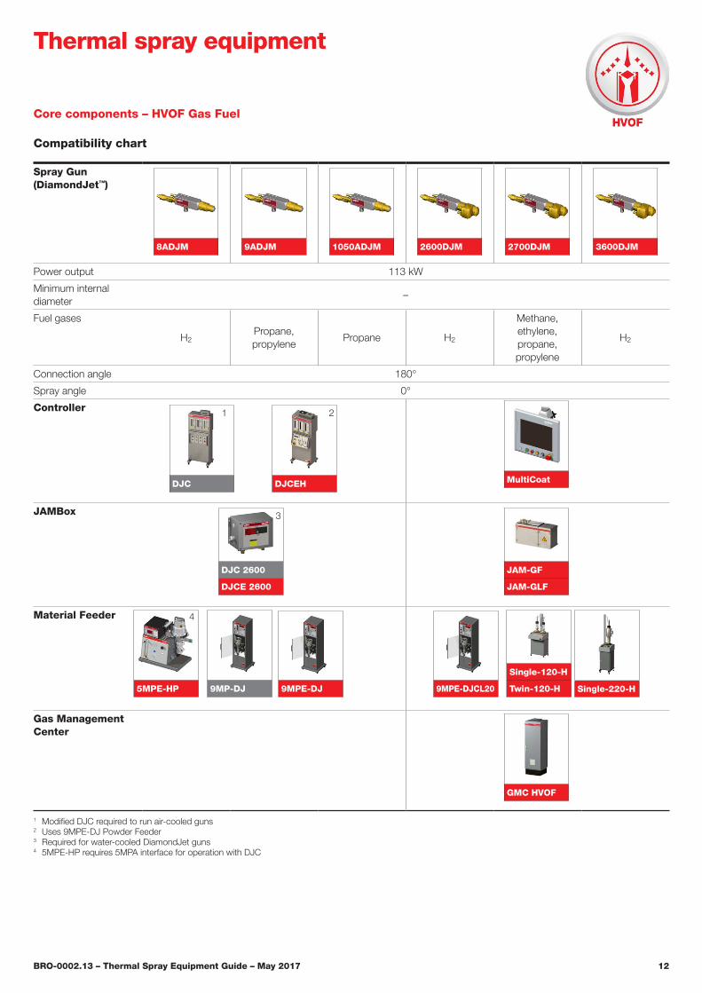
BRO-0002.13 – Thermal Spray Equipment Guide – May 2017 12
Spray Gun(DiamondJet™)
8ADJM 9ADJM 1050ADJM 2600DJM 2700DJM 3600DJM
Power output 113 kW
Minimum internal diameter
–
Fuel gases
H2Propane, propylene
Propane H2
Methane, ethylene, propane, propylene
H2
Connection angle 180°
Spray angle 0°
Controller
JAMBox
Material Feeder
Gas Management Center
DJC
DJC 2600
DJCE 2600
Core components – HVOF Gas Fuel
Compatibility chart
1 Modified DJC required to run air-cooled guns2 Uses 9MPE-DJ Powder Feeder3 Required for water-cooled DiamondJet guns4 5MPE-HP requires 5MPA interface for operation with DJC
Thermal spray equipment
1
3
GMC HVOF
5MPE-HP 9MP-DJ 9MPE-DJ
Single-120-H
Twin-120-H Single-220-H9MPE-DJCL20
DJCEH MultiCoat
JAM-GF
JAM-GLF
4
2
BRO-0002.13 – Thermal Spray Equipment Guide – May 2017 13
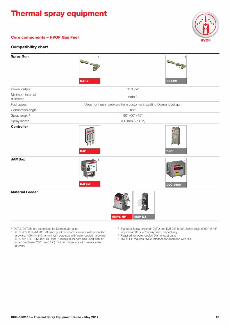
Core components – HVOF Gas Fuel
Compatibility chart
Spray Gun
DJT-2
DJT-2M
Power output 113 kW
Minimum internal diameter
note 2
Fuel gases Uses front gun hardware from customer’s existing DiamondJet gun
Connection angle 180°
Spray angle 3 90° / 60° / 45°
Spray length 700 mm (27.6 in)
Controller
DJF
DJC
JAMBox
DJFEW DJC 2600
Material Feeder
5MPE-HP 9MP-DJ
1 DJT-2, DJT-2M are extensions for DiamondJet guns2 DJT-2 90°/ DJT-2M 90°: 230 mm (9 in) minimum bore size with air-cooled
hardware; 400 mm (16 in) minimum bore size with water-cooled hardware DJT-2 45° / DJT-2M 45°: 180 mm (7 in) minimum bore size used with air-cooled hardware; 280 mm (11 in) minimum bore size with water-cooled hardware
3 Standard Spray angle for DJT-2 and DJT-2M is 90°. Spray angle of 60° or 45° requires a 60° or 45° spray head, respectively
4 Required for water-cooled DiamondJet guns5 5MPE-HP requires 5MPA interface for operation with DJC
Thermal spray equipment
1
5
1
4 4
BRO-0002.13 – Thermal Spray Equipment Guide – May 2017 14
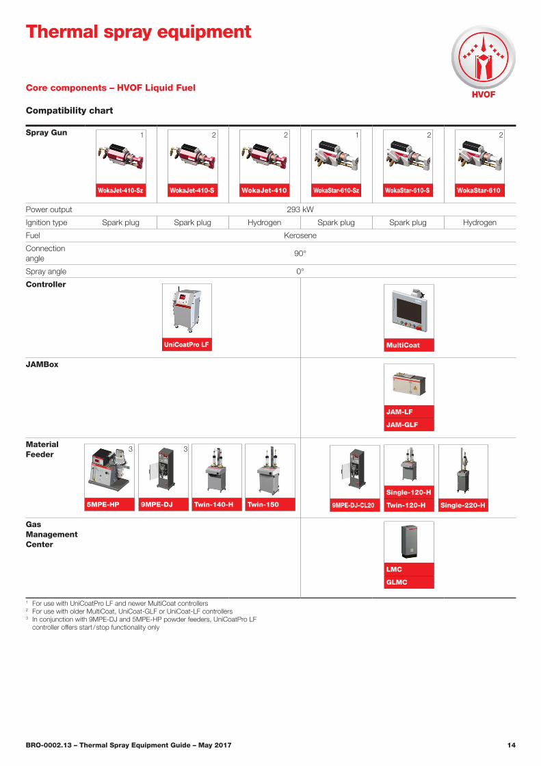
Core components – HVOF Liquid Fuel
Compatibility chart
Spray Gun
WokaJet-410-Sz WokaJet-410-S WokaJet-410 WokaStar-610-Sz WokaStar-610-S WokaStar-610
Power output 293 kW
Ignition type Spark plug Spark plug Hydrogen Spark plug Spark plug Hydrogen
Fuel Kerosene
Connection angle
90°
Spray angle 0°
Controller
JAMBox
Material Feeder
Gas Management Center
1 For use with UniCoatPro LF and newer MultiCoat controllers2 For use with older MultiCoat, UniCoat-GLF or UniCoat-LF controllers3 In conjunction with 9MPE-DJ and 5MPE-HP powder feeders, UniCoatPro LF
controller offers start / stop functionality only
Thermal spray equipment
5
1 2 2 1 2 2
UniCoatPro LF MultiCoat
JAM-LF
JAM-GLF
Twin-150Twin-140-H
Single-120-H
Twin-120-H Single-220-H9MPE-DJ 9MPE-DJ-CL205MPE-HP
3 3
LMC
GLMC
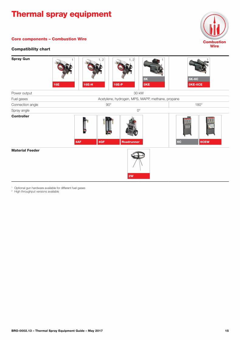
BRO-0002.13 – Thermal Spray Equipment Guide – May 2017 15
Spray Gun
16E 16E-H 16E-P
5K
5KE
5K-6C
5KE-6CE
Power output 30 kW
Fuel gases Acetylene, hydrogen, MPS, MAPP, methane, propane
Connection angle 90° 180°
Spray angle 0°
Controller
4AF
4GF
Roadrunner
6C
6CEW
Material Feeder
2W
Core components – Combustion Wire
Compatibility chart
1 Optional gun hardware available for different fuel gases2 High throughput versions available
Thermal spray equipment
1 1, 2 11, 2 1
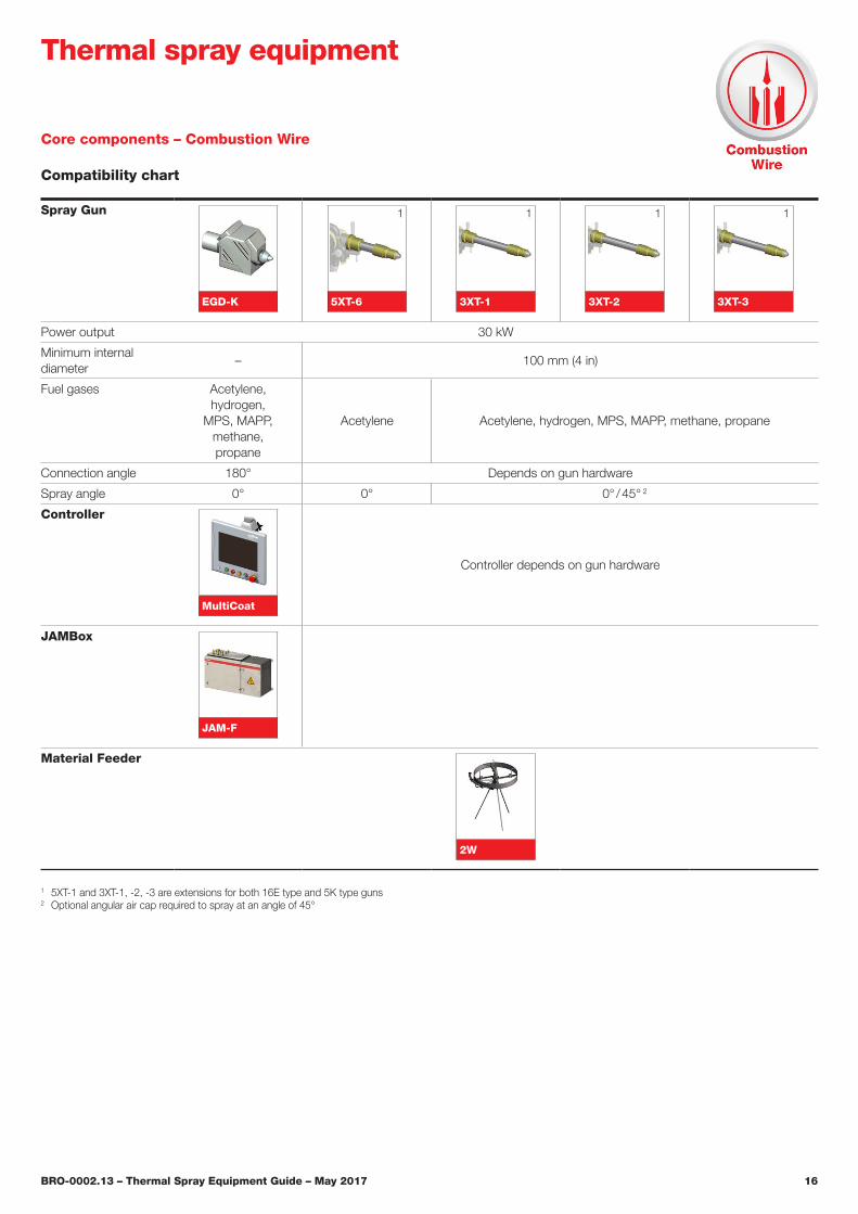
BRO-0002.13 – Thermal Spray Equipment Guide – May 2017 16
Core components – Combustion Wire
Compatibility chart
Thermal spray equipment
Spray Gun
EGD-K 5XT-6 3XT-1 3XT-2 3XT-3
Power output 30 kW
Minimum internal diameter
– 100 mm (4 in)
Fuel gases Acetylene, hydrogen,
MPS, MAPP,methane,propane
Acetylene Acetylene, hydrogen, MPS, MAPP, methane, propane
Connection angle 180° Depends on gun hardware
Spray angle 0° 0° 0° / 45° 2
Controller
MultiCoat
Controller depends on gun hardware
JAMBox
JAM-F
Material Feeder
2W
1 5XT-1 and 3XT-1, -2, -3 are extensions for both 16E type and 5K type guns2 Optional angular air cap required to spray at an angle of 45°
1 1 1 1
BRO-0002.13 – Thermal Spray Equipment Guide – May 2017 17
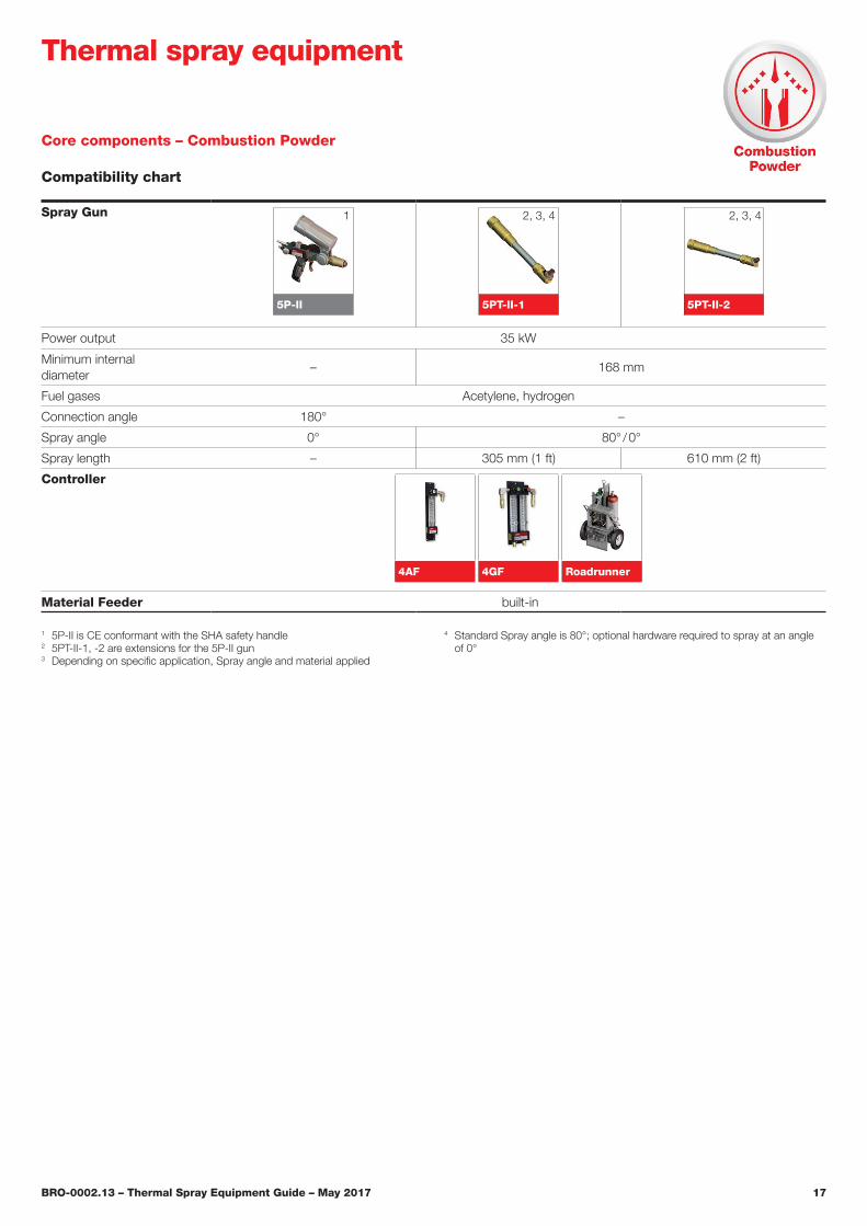
Core components – Combustion Powder
Compatibility chart
Thermal spray equipment
Spray Gun
5P-II 5PT-II-1 5PT-II-2
Power output 35 kW
Minimum internal diameter
– 168 mm
Fuel gases Acetylene, hydrogen
Connection angle 180° –
Spray angle 0° 80° / 0°
Spray length – 305 mm (1 ft) 610 mm (2 ft)
Controller
4AF
4GF
Roadrunner
Material Feeder built-in
1 5P-II is CE conformant with the SHA safety handle2 5PT-II-1, -2 are extensions for the 5P-II gun3 Depending on specific application, Spray angle and material applied
4 Standard Spray angle is 80°; optional hardware required to spray at an angle of 0°
1 2, 3, 4 2, 3, 4
BRO-0002.13 – Thermal Spray Equipment Guide – May 2017 18
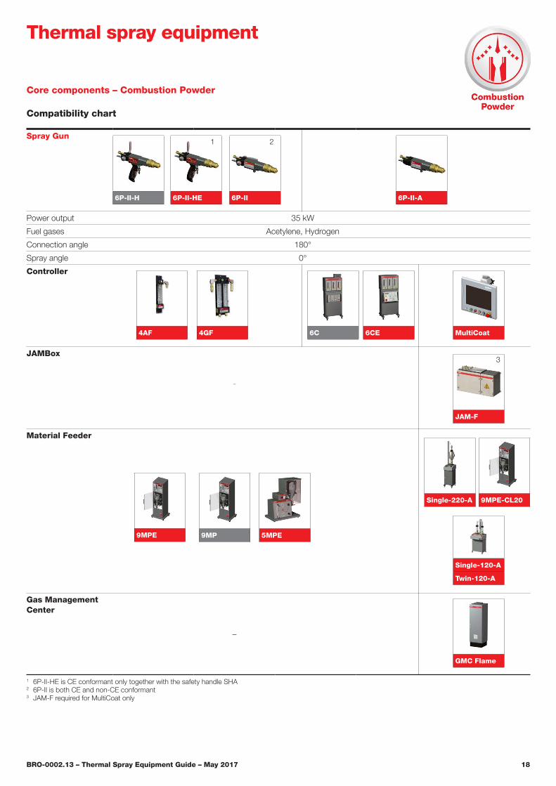
Core components – Combustion Powder
Compatibility chart
Thermal spray equipment
Spray Gun
Power output 35 kW
Fuel gases Acetylene, Hydrogen
Connection angle 180°
Spray angle 0°
Controller
JAMBox
–
Material Feeder
Gas Management Center
–
1 6P-II-HE is CE conformant only together with the safety handle SHA2 6P-II is both CE and non-CE conformant3 JAM-F required for MultiCoat only
4AF 4GF 6C 6CE MultiCoat
JAM-F
3
5MPE
Single-120-A
Twin-120-A
Single-220-A 9MPE-CL20
9MPE 9MP
6P-II-A
GMC Flame
6P-II6P-II-HE6P-II-H
1 2
BRO-0002.13 – Thermal Spray Equipment Guide – May 2017 19
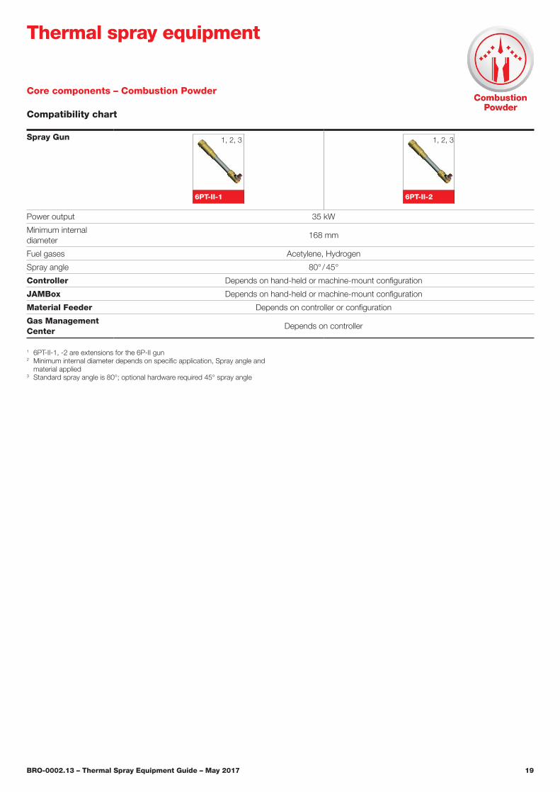
Core components – Combustion Powder
Compatibility chart
Thermal spray equipment
Spray Gun
6PT-II-1 6PT-II-2
Power output 35 kW
Minimum internal diameter
168 mm
Fuel gases Acetylene, Hydrogen
Spray angle 80° / 45°
Controller Depends on hand-held or machine-mount configuration
JAMBox Depends on hand-held or machine-mount configuration
Material Feeder Depends on controller or configuration
Gas Management Center
Depends on controller
1 6PT-II-1, -2 are extensions for the 6P-II gun2 Minimum internal diameter depends on specific application, Spray angle and
material applied3 Standard spray angle is 80°; optional hardware required 45° spray angle
1, 2, 3 1, 2, 3
BRO-0002.13 – Thermal Spray Equipment Guide – May 2017 20
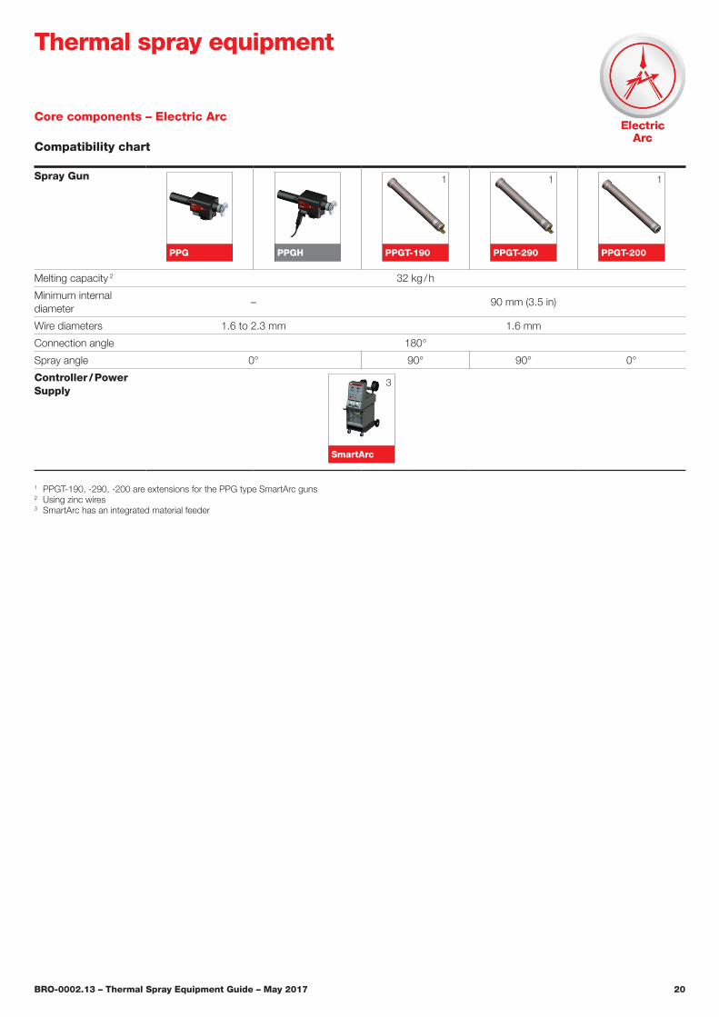
Spray Gun
PPG PPGH PPGT-190 PPGT-290 PPGT-200
Melting capacity 2 32 kg / h
Minimum internal diameter
– 90 mm (3.5 in)
Wire diameters 1.6 to 2.3 mm 1.6 mm
Connection angle 180°
Spray angle 0° 90° 90° 0°
Controller / Power Supply
SmartArc
Core components – Electric Arc
Compatibility chart
Thermal spray equipment
1 PPGT-190, -290, -200 are extensions for the PPG type SmartArc guns2 Using zinc wires3 SmartArc has an integrated material feeder
1
3
1 1
BRO-0002.13 – Thermal Spray Equipment Guide – May 2017 21
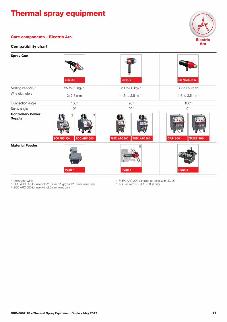
Core components – Electric Arc
Compatibility chart
Thermal spray equipment
Spray Gun
LD / U3 LD / U2 LD / Schub 5
Melting capacity 1 25 to 60 kg / h 20 to 30 kg / h 30 to 35 kg / h
Wire diameters2 / 2.5 mm 1.6 to 2.5 mm 1.6 to 2.5 mm
Connection angle 180° 90° 180°
Spray angle 0° 90° 0°
Controller / Power Supply
ECO ARC 350 ECO ARC 600 FLEXI ARC 200 FLEXI ARC 300 CAP 300 TUBE 300
Material Feeder
Push 4 Push 1 Push 6
1 Using zinc wires2 ECO ARC 350 for use with 2.3 mm (11 ga) and 2.5 mm wires only3 ECO ARC 600 for use with 2.5 mm wires only
4 FLEXI ARC 300 can also be used with LD / U35 For use with FLEXI ARC 300 only
2 3
5
4
BRO-0002.13 – Thermal Spray Equipment Guide – May 2017 22
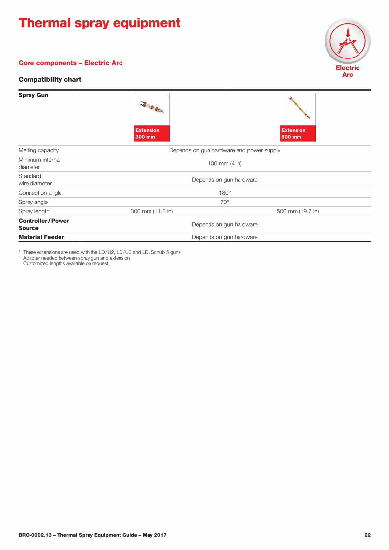
Core components – Electric Arc
Compatibility chart
Thermal spray equipment
Spray Gun
Extension 300 mm
Extension 500 mm
Melting capacity Depends on gun hardware and power supply
Minimum internal diameter
100 mm (4 in)
Standard wire diameter
Depends on gun hardware
Connection angle 180°
Spray angle 70°
Spray length 300 mm (11.8 in) 500 mm (19.7 in)
Controller / Power Source
Depends on gun hardware
Material Feeder Depends on gun hardware
1 These extensions are used with the LD / U2, LD / U3 and LD / Schub 5 guns Adapter needed between spray gun and extension Customized lengths available on request
1
BRO-0002.13 – Thermal Spray Equipment Guide – May 2017 23
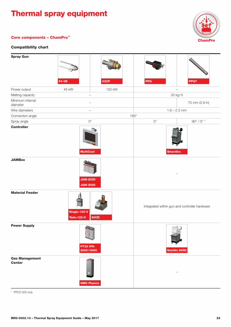
Core components – ChamPro™
Compatibility chart
Thermal spray equipment
Spray Gun
F4-VB 03CP PPG PPGT
Power output 45 kW 120 kW –
Melting capacity – 32 kg / h
Minimum internal diameter
– 70 mm (2.8 in)
Wire diameters – 1.6 – 2.3 mm
Connection angle 180°
Spray angle 0° 0° 90° / 0° 1
Controller
MultiCoat SmartArc
JAMBox
JAM-2030
JAM-3030
–
Material Feeder
Single-120-V
Twin-120-V
60CD
Integrated within gun and controller hardware
Power Supply
PT3X IPS-2000 / 3000 SmartArc 350RU
Gas Management Center
GMC Plasma
–
1 PPGT-200 only
BRO-0002.13 – Thermal Spray Equipment Guide – May 2017 24
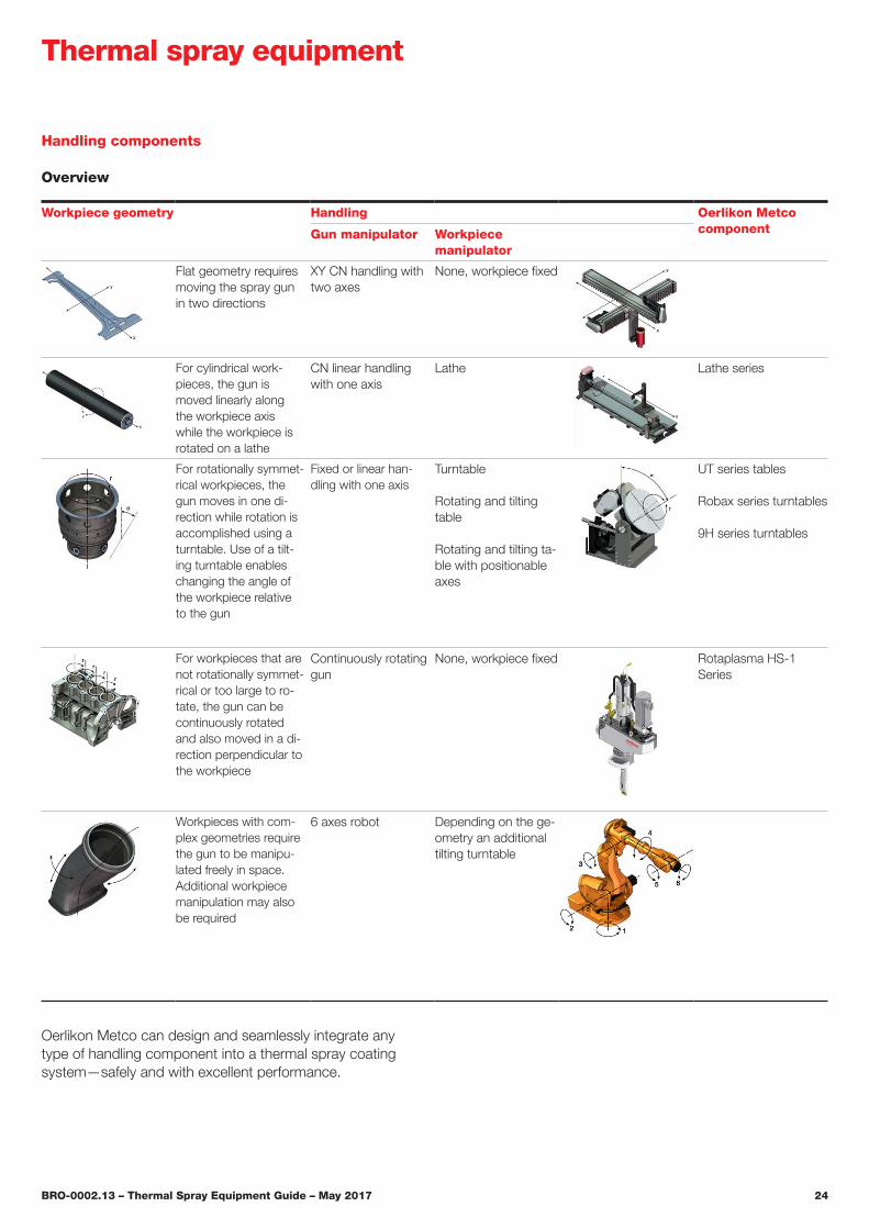
Handling components
Overview
Thermal spray equipment
Workpiece geometry Handling Oerlikon Metco componentGun manipulator Workpiece
manipulator
Flat geometry requires moving the spray gun in two directions
XY CN handling with two axes
None, workpiece fixed
For cylindrical work-pieces, the gun is moved linearly along the workpiece axis while the workpiece is rotated on a lathe
CN linear handling with one axis
Lathe Lathe series
For rotationally symmet-rical workpieces, the gun moves in one di-rection while rotation is accomplished using a turntable. Use of a tilt-ing turntable enables changing the angle of the workpiece relative to the gun
Fixed or linear han-dling with one axis
Turntable
Rotating and tilting table
Rotating and tilting ta-ble with positionable axes
UT series tables
Robax series turntables
9H series turntables
For workpieces that are not rotationally symmet-rical or too large to ro-tate, the gun can be continuously rotated and also moved in a di-rection perpendicular to the workpiece
Continuously rotating gun
None, workpiece fixed Rotaplasma HS-1 Series
Workpieces with com-plex geometries require the gun to be manipu-lated freely in space. Additional workpiece manipulation may also be required
6 axes robot Depending on the ge-ometry an additional tilting turntable
Oerlikon Metco can design and seamlessly integrate any type of handling component into a thermal spray coating system—safely and with excellent performance.
BRO-0002.13 – Thermal Spray Equipment Guide – May 2017 25
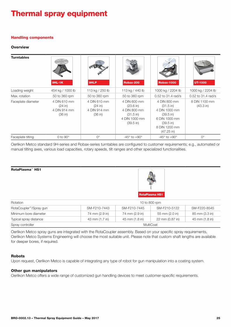
RotaPlasma™ HS1
Rotation 10 to 800 rpm
RotaCoupler™/Spray gun SM-F210-7443 SM-F210-7445 SM-F210-5122 SM-F220-8545
Minimum bore diameter 74 mm (2.9 in) 74 mm (2.9 in) 55 mm (2.0 in) 85 mm (3.3 in)
Typical spray distance 43 mm (1.7 in) 45 mm (1.8 in) 22 mm (0.87 in) 45 mm (1.8 in)
Spray controller MultiCoat
Oerlikon Metco spray guns are integrated with the RotaCoupler assembly. Based on your specific spray requirements, Oerlikon Metco Systems Engineering will choose the most suitable unit. Please note that custom shaft lengths are available for deeper bores, if required.
Turntables
Loading weight 454 kg / 1000 lb 113 kg / 250 lb 113 kg / 440 lb 1000 kg / 2204 lb 1000 kg / 2204 lb
Max� rotation 50 to 360 rpm 50 to 360 rpm 50 to 360 rpm 0�52 to 31�4 rad/s 0�52 to 31�4 rad/s
Faceplate diameter 4 DIN 610 mm (24 in)
4 DIN 914 mm (36 in)
4 DIN 610 mm (24 in)
4 DIN 914 mm (36 in)
4 DIN 600 mm (23�6 in)
4 DIN 800 mm (31�5 in)
4 DIN 1000 mm (39�5 in)
4 DIN 800 mm (31�5 in)
4 DIN 1000 mm (39�5 in)
6 DIN 1000 mm (39�5 in)
8 DIN 1200 mm (47�25 in)
8 DIN 1100 mm (43�3 in)
Faceplate tilting 0 to 90° 0° -45° to +90° -45° to +90° 0°
Oerlikon Metco standard 9H-series and Robax-series turntables are configured to customer requirements; e.g., automated or manual tilting axes, various load capacities, rotary speeds, tilt ranges and other specialized functionalities.
Handling components
Overview
Thermal spray equipment
RotaPlasma HS1
RobotsUpon request, Oerlikon Metco is capable of integrating any type of robot for gun manipulation into a coating system.
Other gun manipulatorsOerlikon Metco offers a wide range of customized gun handling devices to meet customer-specific requirements.
Robax-200 Robax-1000 UT-10009HLP9HL-1K
BRO-0002.13 – Thermal Spray Equipment Guide – May 2017 26
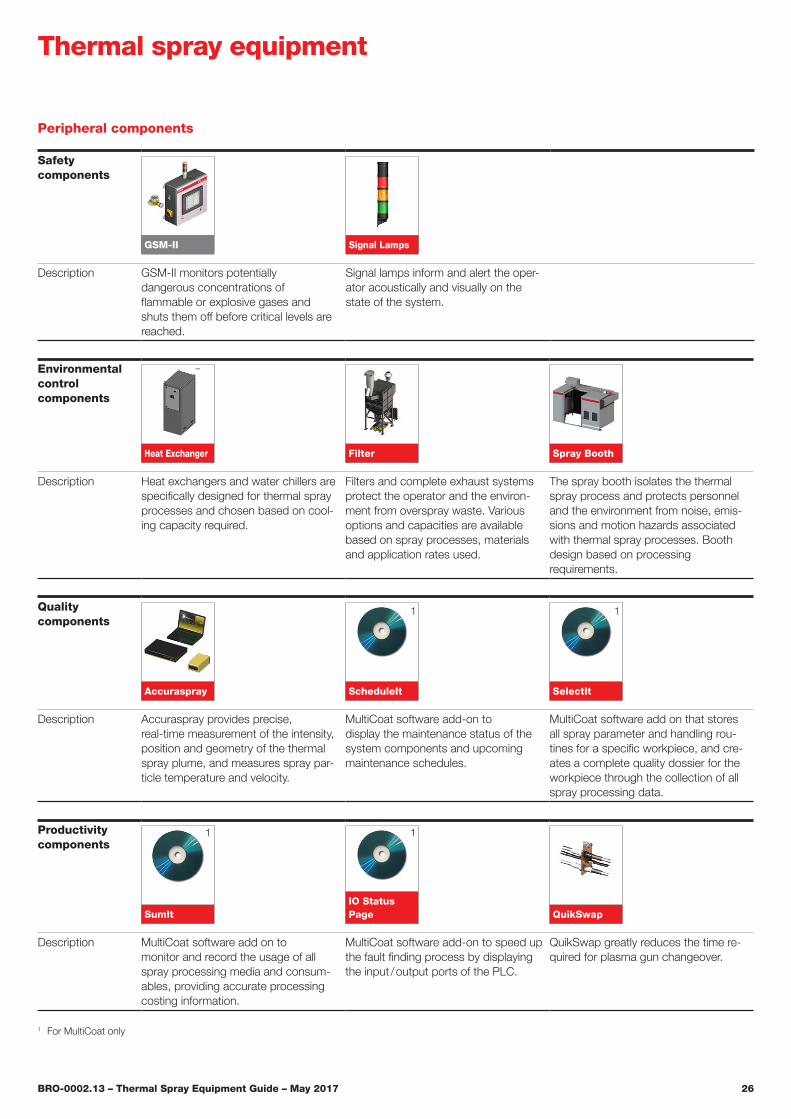
Peripheral components
Thermal spray equipment
Safety components
GSM-II Signal Lamps
Description GSM-II monitors potentially dangerous concentrations of flammable or explosive gases and shuts them off before critical levels are reached�
Signal lamps inform and alert the oper-ator acoustically and visually on the state of the system.
Environmental control components
Heat Exchanger Filter Spray Booth
Description Heat exchangers and water chillers are specifically designed for thermal spray processes and chosen based on cool-ing capacity required.
Filters and complete exhaust systems protect the operator and the environ-ment from overspray waste. Various options and capacities are available based on spray processes, materials and application rates used.
The spray booth isolates the thermal spray process and protects personnel and the environment from noise, emis-sions and motion hazards associated with thermal spray processes. Booth design based on processing requirements.
Quality components
Accuraspray ScheduleIt SelectIt
Description Accuraspray provides precise, real-time measurement of the intensity, position and geometry of the thermal spray plume, and measures spray par-ticle temperature and velocity.
MultiCoat software add-on to display the maintenance status of the system components and upcoming maintenance schedules.
MultiCoat software add on that stores all spray parameter and handling rou-tines for a specific workpiece, and cre-ates a complete quality dossier for the workpiece through the collection of all spray processing data.
Productivity components
SumItIO Status Page QuikSwap
Description MultiCoat software add on to monitor and record the usage of all spray processing media and consum-ables, providing accurate processing costing information.
MultiCoat software add-on to speed up the fault finding process by displaying the input / output ports of the PLC.
QuikSwap greatly reduces the time re-quired for plasma gun changeover.
1 For MultiCoat only
1
1
1
1
BRO-0002.13 – Thermal Spray Equipment Guide – May 2017 27
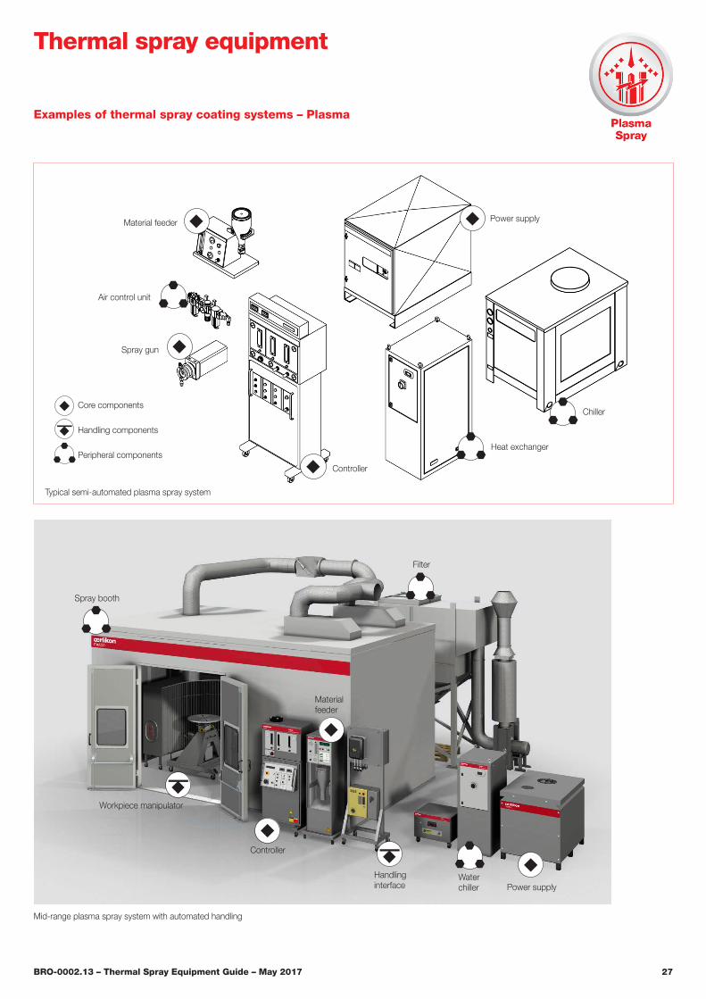
Examples of thermal spray coating systems – Plasma
Thermal spray equipment
Typical semi-automated plasma spray system
Mid-range plasma spray system with automated handling
Filter
Materialfeeder
Handlinginterface
Controller
Spray booth
Power supplyWaterchiller
Workpiece manipulator
Material feeder
Air control unit
Spray gun
Controller
Heat exchanger
Chiller
Power supply
Core components
Handling components
Peripheral components
BRO-0002.13 – Thermal Spray Equipment Guide – May 2017 28
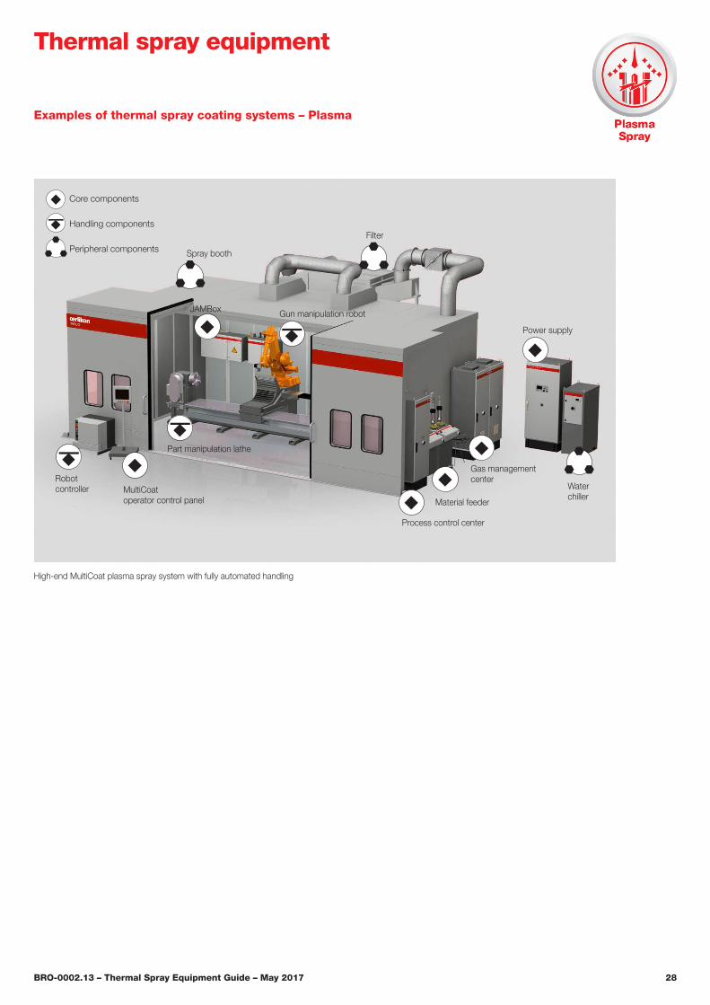
Examples of thermal spray coating systems – Plasma
Thermal spray equipment
Waterchiller
Filter
Material feeder
JAMBox Gun manipulation robot
Part manipulation lathe
MultiCoatoperator control panel
Power supply
Process control center
Spray booth
Robot controller
Gas managementcenter
High-end MultiCoat plasma spray system with fully automated handling
Core components
Handling components
Peripheral components
BRO-0002.13 – Thermal Spray Equipment Guide – May 2017 29
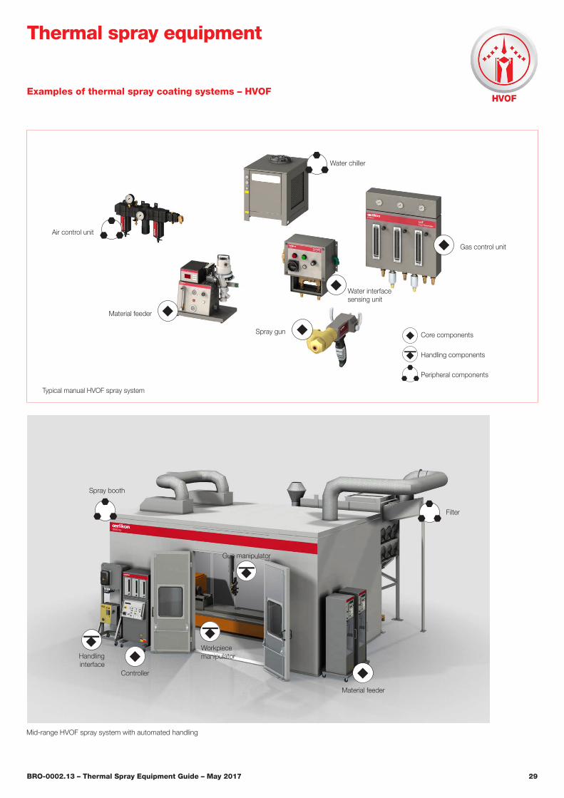
Examples of thermal spray coating systems – HVOF
Thermal spray equipment
Typical manual HVOF spray system
Material feeder
Air control unit
Spray gun
Water interface sensing unit
Gas control unit
Water chiller
Core components
Handling components
Peripheral components
Mid-range HVOF spray system with automated handling
Filter
Material feeder
Handling interface
Controller
Spray booth
Gun manipulator
Workpiecemanipulator
BRO-0002.13 – Thermal Spray Equipment Guide – May 2017 30
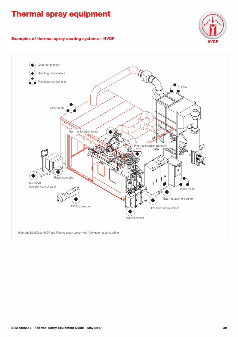
Water chiller
Filter
Material feeder
Gun manipulation robot
Spray booth
HVOF spray gun
Robot controller
Gas management center
Process control center
High-end MultiCoat HVOF and Plasma spray system with fully automated handling
Core components
Handling components
Peripheral components
MultiCoatoperator control panel
Part manipulation turntable
Examples of thermal spray coating systems – HVOF
Thermal spray equipment
BRO-0002.13 – Thermal Spray Equipment Guide – May 2017 31
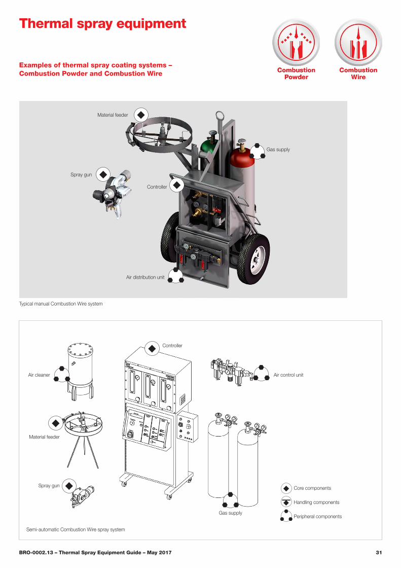
Examples of thermal spray coating systems – Combustion Powder and Combustion Wire
Thermal spray equipment
Typical manual Combustion Wire system
Semi-automatic Combustion Wire spray system
Air distribution unit
Air control unit
Spray gun
Gas supply
Gas supply
Controller
Air cleaner
Material feeder
Controller
Spray gun Core components
Handling components
Peripheral components
Material feeder
BRO-0002.13 – Thermal Spray Equipment Guide – May 2017 32
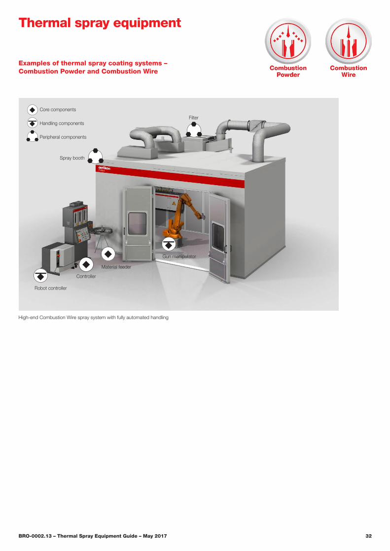
Examples of thermal spray coating systems – Combustion Powder and Combustion Wire
Thermal spray equipment
High-end Combustion Wire spray system with fully automated handling
Filter
Material feeder
Robot controller
Controller
Spray booth
Gun manipulator
Core components
Handling components
Peripheral components
BRO-0002.13 – Thermal Spray Equipment Guide – May 2017 33
Examples of thermal spray coating systems – Electric Arc
Thermal spray equipment
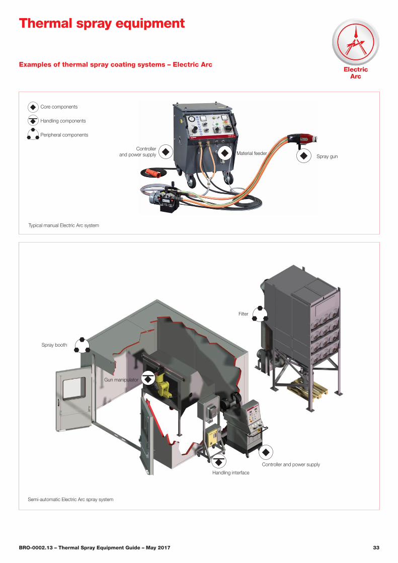
Typical manual Electric Arc system
Semi-automatic Electric Arc spray system
Spray gun
Controllerand power supply
Controller and power supply
Material feeder
Filter
Handling interface
Spray booth
Gun manipulator
Core components
Handling components
Peripheral components

BRO-0002.13 – Thermal Spray Equipment Guide – May 2017 34
Examples of thermal spray coating systems – Electric Arc
Thermal spray equipment
Filter
Gun manipulation robot
Part manipulation turntable
Spray booth
Robot controller
High-end Electric Arc spray system with fully automated handling
Controllerand power supply
Core components
Handling components
Peripheral components
BRO-0002.13 – Thermal Spray Equipment Guide – May 2017 35
Examples of thermal spray coating systems – ChamPro™
Thermal spray equipment
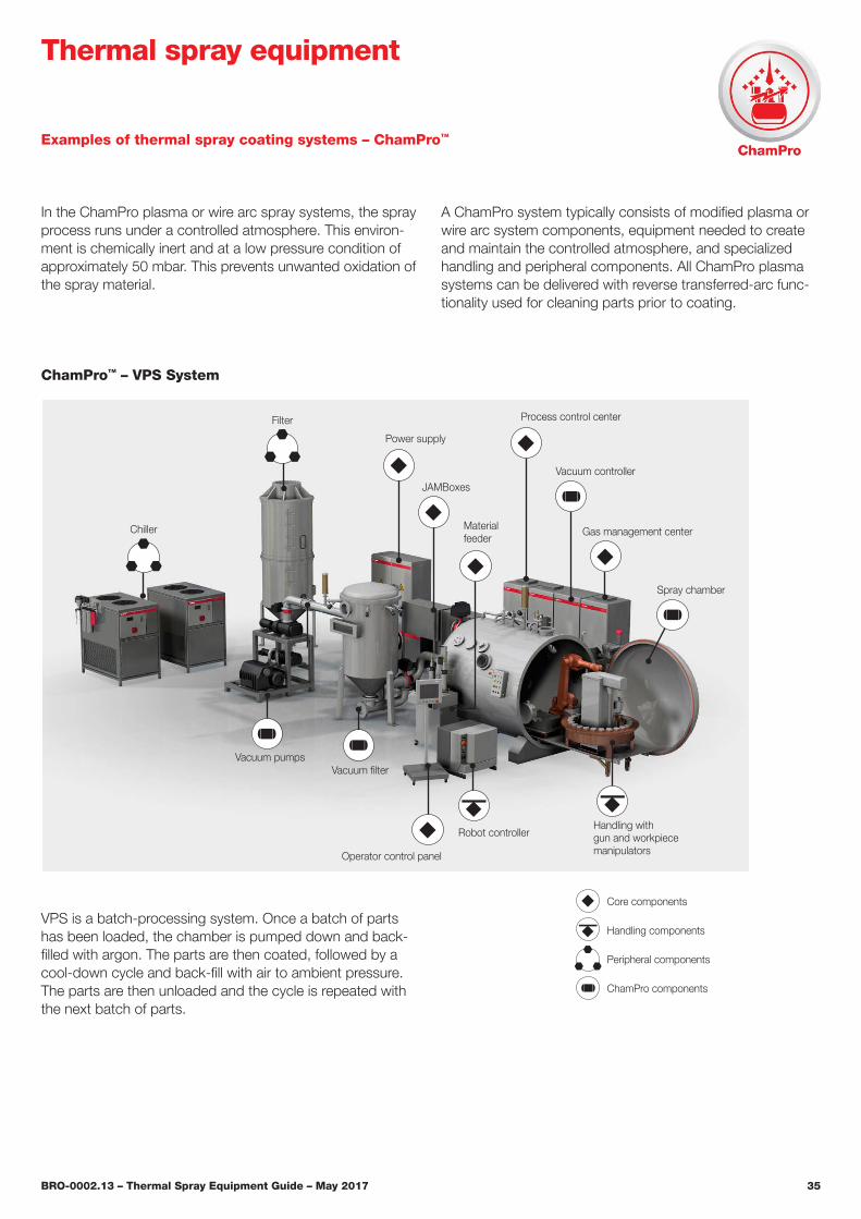
In the ChamPro plasma or wire arc spray systems, the spray process runs under a controlled atmosphere. This environ-ment is chemically inert and at a low pressure condition of approximately 50 mbar. This prevents unwanted oxidation of the spray material.
A ChamPro system typically consists of modified plasma or wire arc system components, equipment needed to create and maintain the controlled atmosphere, and specialized handling and peripheral components. All ChamPro plasma systems can be delivered with reverse transferred-arc func-tionality used for cleaning parts prior to coating.
VPS is a batch-processing system. Once a batch of parts has been loaded, the chamber is pumped down and back-filled with argon. The parts are then coated, followed by a cool-down cycle and back-fill with air to ambient pressure. The parts are then unloaded and the cycle is repeated with the next batch of parts.
Vacuum filter
Filter
Vacuum controller
Materialfeeder
Robot controller
Operator control panel
Handling with gun and workpiece manipulators
Spray chamber
Chiller
Power supply
JAMBoxes
Gas management center
Process control center
Vacuum pumps
Core components
Handling components
Peripheral components
ChamPro components
ChamPro™ – VPS System
BRO-0002.13 – Thermal Spray Equipment Guide – May 2017 36
Thermal spray equipment
Examples of thermal spray coating systems – ChamPro™
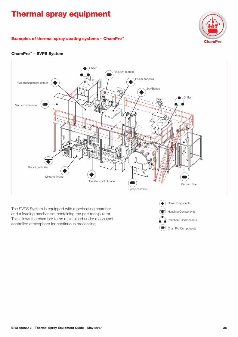
ChamPro™ – SVPS System
The SVPS System is equipped with a preheating chamber and a loading mechanism containing the part manipulator. This allows the chamber to be maintained under a constant, controlled atmosphere for continuous processing.
Vacuum pumps
Vacuum filter
Gas management center
Vacuum controller
Material feeder
Robot controller
Operator control panel
Spray chamber
JAMBoxes
Chiller
Power supplies
Chiller
Core Components
Handling Components
Peripheral Components
ChamPro Components
BRO-0002.13 – Thermal Spray Equipment Guide – May 2017 37
Thermal spray equipment
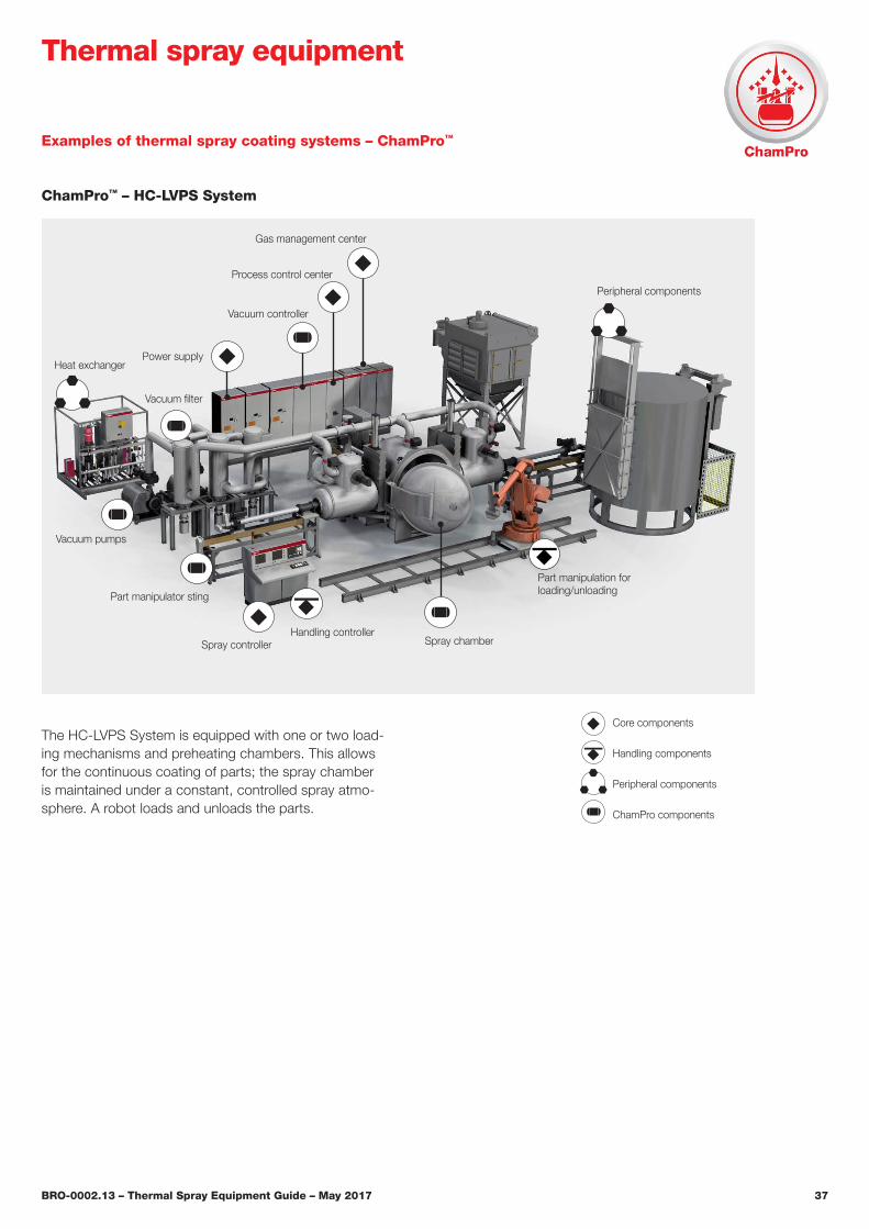
Vacuum pumps
Vacuum filter
Gas management center
Process control center
Vacuum controller
Spray controllerHandling controller
Spray chamber
Part manipulator sting
Heat exchangerPower supply
The HC-LVPS System is equipped with one or two load-ing mechanisms and preheating chambers. This allows for the continuous coating of parts; the spray chamber is maintained under a constant, controlled spray atmo-sphere. A robot loads and unloads the parts.
ChamPro™ – HC-LVPS System
Examples of thermal spray coating systems – ChamPro™
Core components
Handling components
Peripheral components
ChamPro components
Peripheral components
Part manipulation for loading/unloading
BRO-0002.13 – Thermal Spray Equipment Guide – May 2017 38
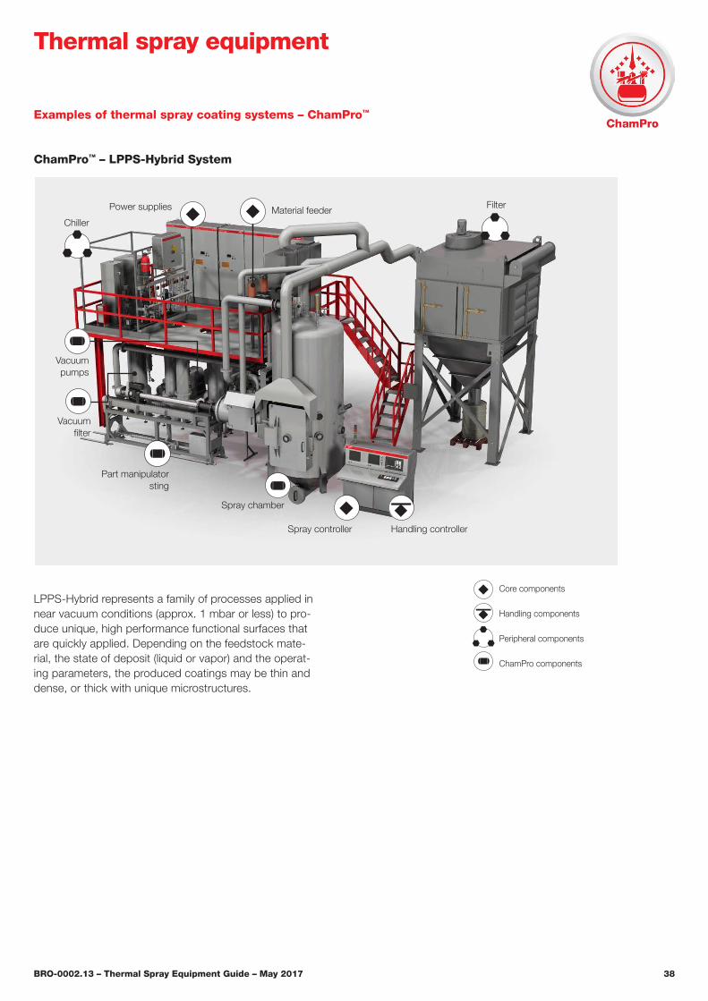
Thermal spray equipment
LPPS-Hybrid represents a family of processes applied in near vacuum conditions (approx. 1 mbar or less) to pro-duce unique, high performance functional surfaces that are quickly applied. Depending on the feedstock mate-rial, the state of deposit (liquid or vapor) and the operat-ing parameters, the produced coatings may be thin and dense, or thick with unique microstructures.
ChamPro™ – LPPS-Hybrid System
Examples of thermal spray coating systems – ChamPro™
Vacuumpumps
Vacuumfilter
FilterMaterial feeder
Spray controller Handling controller
Spray chamber
Power supplies
Chiller
Part manipulatorsting
Core components
Handling components
Peripheral components
ChamPro components

BRO-0002.13 – Thermal Spray Equipment Guide – May 2017 39
Notes
BRO-0002.13 – Thermal Spray Equipment Guide – May 2017 40
About Oerlikon MetcoOerlikon Metco enhances surfaces that bring benefits to customers through a uniquely broad range of surface technologies, equipment, materials, services, specialized machining services and components. The surface techno logies such as Thermal Spray and Laser Cladding improve the performance and increase effi-ciency and reliability. Oerlikon Metco serves industries such as aviation, power gen-eration, automotive, oil & gas, industrial and other specialized markets and oper-ates a dynamically growing network of more than 50 sites in EMEA, Americas and Asia Pacific. Oerlikon Metco, together with Oerlikon Balzers, belongs to the Sur-face Solutions Segment of the Switzerland- based Oerlikon Group.
Information is subject to change without prior notice.
www.oerlikon.com/metco [email protected]
Thermal spray equipmentAdvanced Technology Solutions and Services
Perfect solutions through optimum materials and innovative technologiesOerlikon Metco is a global leader in surface engineering solutions and services offering:
n A broad range of thermal spray, la-ser cladding and other advanced surface technology equipment
n Integrated systems and materials n Specialized coating and surface en-
hancement services n Manufactured components for the
turbine, automotive and other industries
n Customer support services
Oerlikon Metco provides a comprehensive manufacturing, distribution and service network, catering to aviation, power generation, automotive and other strategic growth industries�
To take control of your surface engineering challenges, contact your Oerlikon Metco sales office, visit our web site at www.oerlikon.com/metco or e-mail us at [email protected]�