Embed Size (px)
Citation preview
Thermal Model of Cylindrical Trough Collector
Receiver 1Parvathi Gorantla and
2B. Janarthanan
1Department of Physics, Karpagam Academy of Higher Education,
Eachanari Post, Pollachi Main Road, Coimbatore.
2Department of Physics, Karpagam Academy of Higher Education,
Eachanari Post, Pollachi Main Road, Coimbatore.
Abstract An attempt is made to design, fabricate and analyze a cylindrical trough
solar collector system. An Evacuated Aluminium receiver has been used in
the focal plane of the system to receive the thermal energy and water has been
used as the heat transfer fluid to collect the thermal energy from the present
system. Different heat transfer mechanisms, i.e., the heat transfer mechanism
through convection of the internal receiver, in the circular among the linear
receiver tube and cover glass, from the cover glass tube to the ambience air,
the heat transfer mechanism through glass cover to the linear receiver tube to
cover glass walls, Radiative heat transfer mechanism through Radiation from
the linear receiver tube to glass cover walls and glass cover surfaces to
ambience have been evaluated and interpreted. Thermal modelling for the
proposed system is done and the results are correlated with the empirical
observations intended for validation of the model.
Key Words:Receiver, cylindrical trough solar collector, heat transfer
mechanism.
International Journal of Pure and Applied MathematicsVolume 116 No. 24 2017, 155-171ISSN: 1311-8080 (printed version); ISSN: 1314-3395 (on-line version)url: http://www.ijpam.euSpecial Issue ijpam.eu
155

I. Introductory Part
To solve energy crisis problem caused by the consumption of conventional fuels
and the solution of atmospheric problems associated with using of fossil fuels in
recent years, Renewable energy is the one of the leading alternative solution.
Therefore, vital using of solar energy attracts millions of the specialists for a
sustainable development of the human being and reducing the environmental
needs. Solar energy is the one of most cheapest clean energies of the among all
renewable energy sources, because of its zero pollution, the production of green
energy and great scenery in the utilization of different areas such as solar
electricity generation in both thermal and photovoltaic modes, heating, cooling
and solar heating and also on saline water distillation.
The Cylindrical Trough Solar Collector (CTSC) is made by flexing of reflective
material into Cylindrical shape. A metal receiver is painted with mat black color
and to diminish the thermal losses, the metal receiver tube is enclosed by a glass
tube and placed along the focal plane of the collector. To absorb the direct and
reflected sun’s energy, the system is continuously tracked towards the motion of
the Sun. The absorbed and reflected sun’s energy heats the heat transfer fluid
surrounding through the receiver and transfigures the solar energy into useful
heat. In general, the Solar collector is located in an East West path to trace the
solar radiation from the North - South direction or the Collector position located
in the North-South path to track the Solar radiation from East-West direction.
The tracking mode influences the collector faces towards the Sun throughout
the day. However, a North-South field collector absorbs more energy in
summer and East-West located collector absorbs more energy in the winter
throughout the year. So the sense of direction confides on application and
season.
The performance of parabolic solar collector has been refined furthermore and
tested by Omar Behar et al. [1] and studied that the proposed thermal model for
the system predicted the accurate thermal efficiency than engineering equation
solver with an average indefinite of 0.64% correlated to 1.11% for Engineering
Equation solver. The energetic and exegetic comparison of various gas working
fluids in a parabolic trough collector is studied by Eyangelos Bellos [2] and
from the results it has been found that the expected exergetic efficiency is
achieved by the Helium with an operating inlet temperature of 640K and
0.035Kg/s mass flow rate. The investigation of optical and thermal evaluation
of a parabolic collector having a absorber painted with matt black paint and
enclosed with glass cover is performed by Devander Kumar and Sudhir Kumar
[3] and the peak instantaneous thermal efficiency is 66.78% in the month of
July in the horizontal mode, 65.77% in September
International Journal of Pure and Applied Mathematics Special Issue
156
on tending planes of collector. Numerical investigation of thermal
characteristics of the receiver tube of a parabolic collector on laminar stream is
presented by Zeng-Yao Li et al. [4] and the results of the study revealed that the
heat transfer of laminar force through has convection greater than 10%
reflecting the advanced Grashof number than a threshold value. Parabolic
trough collector attached with heat storage tank with heater coupled to Kalina
cycle system has been developed by Milad Ashouri et al. [5] and concluded that
electricity exergy efficiency is increased by 5.24% by the exegetic
developement potential of 62%. Evaluation of optical and thermal performances
of parabolic trough collector’s solar efficiency has been done using engineering
equation solver by Esmail MA Mokheimer et al. [6] and the study revealed that
the maximum and minimum values of optical efficiencies are 73.5% and 61%.
A thermal mathematical analysis for a parabolic trough solar collector has been
done by Ibrahim Halil Yılmaz and Mehmet Sait Soylemez [7] and solved using
Engineering equation solver. From the results, it has been found that the
increase in wind speed influence the thermal efficiency of receiver tube related
to vacuum and wind speed effect decreases thermal efficiency greater than bulk
temperature of 150 °C. A detailed model of the optical efficiency of a parabolic
solar collector with the vacuum receiver has been developed by Weidong
Huang et al. [8] and the effects of different errors of the receiver such as optic
installation error, positional error, reflectors optical characterstics, the vacuum
tube receiver Transmittance and absorptivity on the performance of the
proposed trough system fabricated. Yacine Marif et al. [9] have proposed the
optical and thermal efficiencies of a parabolic solar collector under the
atmospheric conditions of the Sahara Algerian and by using computer program,
single dimensional implicative finite difference technique with the energy
balance developed has given thermal efficiency of about 69.73-72.24%. Soteris
A. Kalogirou [10] has presented a comprehensive thermal model of a parabolic
trough collector. Heat transfer mechanism of receiver tube heating by Non
Uniform Heat Flux and the turbulent flow development in receiver tube due to
buoyancy force effect has been developed by Zhen Huang et al. [11]. The
effects of thermal boundary conditions of the Uniform and Non Uniform heat
fluxes at different solar angles 0°,30°,60° and 90° and effects of different
parameters such as Reynolds number (Re), Grashof number (Gr), Richardson
number (Ri) on the thermal analysis of the receiver has been reviewed.
Nomenclatures
a accommodation coefficient of air (-)
Ar Receiver area of the collector (m2)
b interaction coefficient at convection heat transfer (-)
C Heat transfer coefficient through convection(W/m2C)
Cp Water specific heat capacity(J/KgC)
Dirt internal receiver tube diameter (m)
Dort External receiver tube diameter (m)
F Collector efficient factor
firt Receiver inner surface friction factor, (-)
g gravitational constant (=9.8m/s)
hf HTF heat transfer coefficient through convection at Tf(W/m°C)
K Thermal Conduction of water (W/m-°C)
Kf Heat Conduction of the HTF at temperature of the fluid (W/m°C)
Kθ incident angle modifier (-)
m Water mass flow rate (kg/s)
International Journal of Pure and Applied Mathematics Special Issue
157
A numerical investigation of entropy production in a parabolic trough receiver
at different concentric ratios, inlet and outlet temperatures and at different flow
rates has been carried out by Aggrey Mwesigye et al. [12] and the entropy
generation increases with the increase of the concentric ratio of receiver by
using the second law of thermodynamics. Jianfeng Lu et al. [13] have
developed non-uniform heat transfer model and theoretical investigation of the
parabolic trough solar collector receiver and revealed that the heat transfer
achievement of parabolic trough solar receiver show better performance than
non uniform model. Rubén Barbero et al. [14] approached the use of an
analytical expression from the heat balance differential equation and found that
a maximum in efficiency depend on the concentration factor. The effect of
modification of the receiver in low form concentrated solar thermal collector
has been investigated experimentally by Qiyuan Li et al. [15] and the proposed
design suited to industrial and commercial heating applications. The Cylindrical
trough solar collector was most promising solar thermal technology used in the
1970s. The surface of the receiver coated with black paint or selective absorber
coatings for maximum absorption and low thermal emission of solar thermal
radiation. The glass tube is used to diminish the convection heat transfer from
the receiver tube of the collector. The present model considered all the modes of
heat transfer mechanisms ie., heat transfer mechanism through out the Receiver
tube by convection, the annular between receiver tube and the cover glass, from
cover glass to ambient; conduction heat transfer mechanism receiver tube and
the walls of cover glass and the radiation heat transfer mechanism receiver tube
to the surface of cover glass and from the glass tube to ambient.
II. Energy Model of Receiver
The energy balance of the proposed system for the temperature components has
been written to predict the collector’s performance. The equations have been
solved for the analytical expressions for the temperature elements and it
confides on the ambient condition and cylindrical collector’s optical properties.
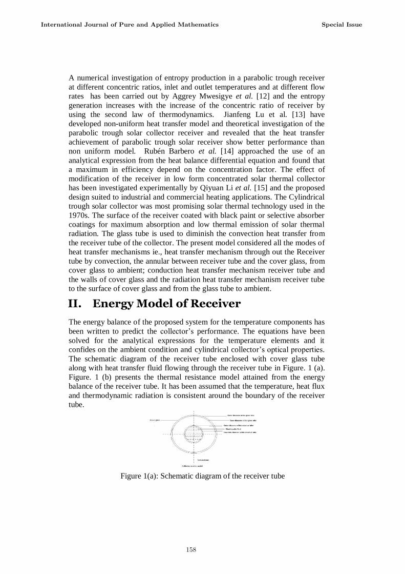
The schematic diagram of the receiver tube enclosed with cover glass tube
along with heat transfer fluid flowing through the receiver tube in Figure. 1 (a).
Figure. 1 (b) presents the thermal resistance model attained from the energy
balance of the receiver tube. It has been assumed that the temperature, heat flux
and thermodynamic radiation is consistent around the boundary of the receiver
tube.
Figure 1(a): Schematic diagram of the receiver tube
International Journal of Pure and Applied Mathematics Special Issue
158
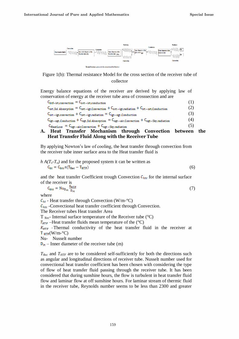
Figure 1(b): Thermal resistance Model for the cross section of the receiver tube of
collector
Energy balance equations of the receiver are derived by applying law of
conservation of energy at the receiver tube area of crosssection and are
(1)
(2)
(3)
(4)
(5)
A. Heat Transfer Mechanism through Convection between the Heat Transfer Fluid Along with the Receiver Tube
By applying Newton’s law of cooling, the heat transfer through convection from
the receiver tube inner surface area to the Heat transfer fluid is
h A(Ts-Tα) and for the proposed system it can be written as
(6)
and the heat transfer Coefficient trough Convection for the internal surface
of the receiver is
(7)
where
- Heat transfer through Convection (W/m-°C)
-Convectional heat transfer coefficient through Convection.
The Receiver tubes Heat transfer Area
T Rec- Internal surface temperature of the Receiver tube (°C)
–Heat transfer fluids mean temperature of the (°C)
–Thermal conductivity of the heat transfer fluid in the receiver at
(W/m-°C)
Nu- Nusselt number
– Inner diameter of the receiver tube (m)
TRec and THTF are to be considered self-sufficiently for both the directions such
as angular and longitudinal directions of receiver tube. Nusselt number used for
convectional heat transfer coefficient has been chosen with considering the type
of flow of heat transfer fluid passing through the receiver tube. It has been
considered that during sunshine hours, the flow is turbulent in heat transfer fluid
flow and laminar flow at off sunshine hours. For laminar stream of thermic fluid
in the receiver tube, Reynolds number seems to be less than 2300 and greater
International Journal of Pure and Applied Mathematics Special Issue
159
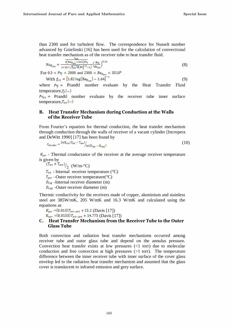
than 2300 used for turbulent flow. The correspondence for Nusselt number
advanced by Gnielinski [16] has been used for the calculation of convectional
heat transfer mechanism as of the receiver tube to heat transfer fluid.
(8)
For
With (9)
where Prandtl number evaluate by the Heat Transfer Fluid
temperature,
Prandtl number evaluate by the receiver tube inner surface
temperature,
B. Heat Transfer Mechanism during Conduction at the Walls of the Receiver Tube
From Fourier’s equation for thermal conduction, the heat transfer mechanism
through conduction through the walls of receiver of a vacant cylinder [Incropera
and DeWitt 1990] [17] has been found by
(10)
- Thermal conductance of the receiver at the average receiver temperature
is given by
(W/m-°C)
- Internal receiver temperature (°C)
–Outer receiver temperature(°C)
-Internal receiver diameter (m)
-Outer receiver diameter (m)
Thermic conductivity for the receivers made of copper, aluminium and stainless
steel are 385W/mK, 205 W/mK and 16.3 W/mK and calculated using the
equations as
= (Davis [17])
= (Davis [17])
C. Heat Transfer Mechanism from the Receiver Tube to the Outer Glass Tube
Both convection and radiation heat transfer mechanisms occurred among
receiver tube and outer glass tube and depend on the annulus pressure.
Convection heat transfer exists at low pressures (<1 torr) due to molecular
conduction and free convection at high pressures (>1 torr). The temperature
difference between the inner receiver tube with inner surface of the cover glass
envelop led to the radiation heat transfer mechanism and assumed that the glass
cover is translucent to infrared emission and grey surface.
International Journal of Pure and Applied Mathematics Special Issue
160
Heat Transfer Mechanism through Convection
The two thermal systems deliberated into the present section are heat transfer
mechanism through convection within receiver tube and the wall of glass
tube(Cirt-igt, conve ), Those are the gratis molecular and natural convectional
mechanisms [18]. These pressure annulus and molecular annulus are tested
separately.
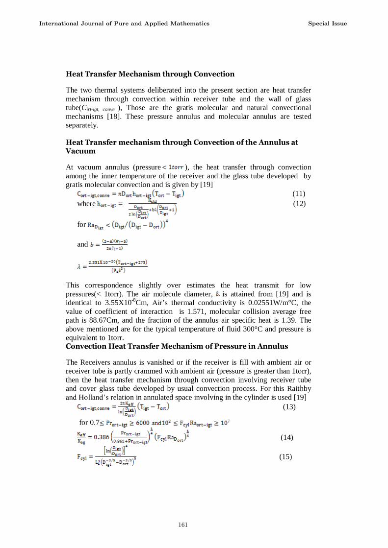
Heat Transfer mechanism through Convection of the Annulus at Vacuum
At vacuum annulus (pressure ), the heat transfer through convection
among the inner temperature of the receiver and the glass tube developed by
gratis molecular convection and is given by [19]
(11)
where (12)
for
and
This correspondence slightly over estimates the heat transmit for low
pressures(< 1torr). The air molecule diameter, is attained from [19] and is
identical to 3.55X10⁻⁸
Cm, Air’s thermal conductivity is 0.02551W/m°C, the
value of coefficient of interaction is 1.571, molecular collision average free
path is 88.67Cm, and the fraction of the annulus air specific heat is 1.39. The
above mentioned are for the typical temperature of fluid 300°C and pressure is
equivalent to 1torr.
Convection Heat Transfer Mechanism of Pressure in Annulus
The Receivers annulus is vanished or if the receiver is fill with ambient air or
receiver tube is partly crammed with ambient air (pressure is greater than 1torr),
then the heat transfer mechanism through convection involving receiver tube
and cover glass tube developed by usual convection process. For this Raithby
and Holland’s relation in annulated space involving in the cylinder is used [19]
(13)
for 0.7
(14)
(15)
International Journal of Pure and Applied Mathematics Special Issue
161
The critical length in the above equations is given by
Where l conduction heat transfer of annulus gas at Tort-igt (W/m°C)
Prandtl number for gas evaluated at
= Reyleigh number calculated at
at this relationship estimates long, straight and concentric cylinder at
standardized temperatures. All physical characteristics are calculated at the
average temperature (Tort+Tigt) /2.
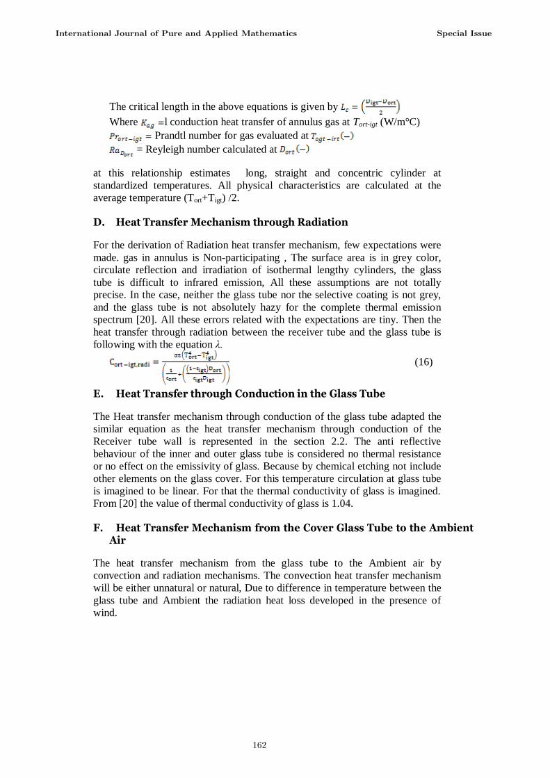
D. Heat Transfer Mechanism through Radiation
For the derivation of Radiation heat transfer mechanism, few expectations were
made. gas in annulus is Non-participating , The surface area is in grey color,
circulate reflection and irradiation of isothermal lengthy cylinders, the glass
tube is difficult to infrared emission, All these assumptions are not totally
precise. In the case, neither the glass tube nor the selective coating is not grey,
and the glass tube is not absolutely hazy for the complete thermal emission
spectrum [20]. All these errors related with the expectations are tiny. Then the
heat transfer through radiation between the receiver tube and the glass tube is
following with the equation λ.
(16)
E. Heat Transfer through Conduction in the Glass Tube
The Heat transfer mechanism through conduction of the glass tube adapted the
similar equation as the heat transfer mechanism through conduction of the
Receiver tube wall is represented in the section 2.2. The anti reflective
behaviour of the inner and outer glass tube is considered no thermal resistance
or no effect on the emissivity of glass. Because by chemical etching not include
other elements on the glass cover. For this temperature circulation at glass tube
is imagined to be linear. For that the thermal conductivity of glass is imagined.
From [20] the value of thermal conductivity of glass is 1.04.
F. Heat Transfer Mechanism from the Cover Glass Tube to the Ambient
Air
The heat transfer mechanism from the glass tube to the Ambient air by
convection and radiation mechanisms. The convection heat transfer mechanism
will be either unnatural or natural, Due to difference in temperature between the
glass tube and Ambient the radiation heat loss developed in the presence of
wind.
International Journal of Pure and Applied Mathematics Special Issue
162
Convectional Heat Transfer
Based on the Nusselt number the heat transfer mechanism through Convection
is influential. On the base of Nusselt number, the type of convective heat
transfer determined. The convection is natural the Nusselt number is less than
2300 or greater than 2300 the convection is forced. From Newton’s law of
cooling the convectional heat transfer from the glass tube to the atmosphere in
the presence of wind.
(17)
(18)
Where = Heat transfer coefficient from convection of air at
(W/m2°C)
Air’s thermal conductivity (W/m°C)
= Mean Nusselt number based on the outer glass tube diameter
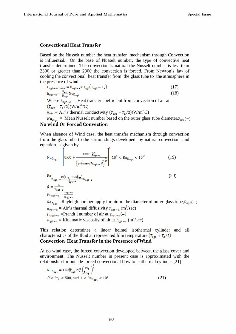
No wind Or Forced Convection
When absence of Wind case, the heat transfer mechanism through convection
from the glass tube to the surroundings developed by natural convection and
equation is given by
(19)
(20)
=Rayleigh number apply for air on the diameter of outer glass tube,
= Air’s thermal diffusivity (m2/sec)
=Prandt l number of air at
Kinematic viscosity of air at (m2/sec)
This relation determines a linear heimel isothermal cylinder and all
characteristics of the fluid at represented film temperature
Convection Heat Transfer in the Presence of Wind
At no wind case, the forced convection developed between the glass cover and
environment. The Nusselt number in present case is approximated with the
relationship for outside forced convectional flow to isothermal cylinder [21]
.7 (21)
International Journal of Pure and Applied Mathematics Special Issue
163
Where C and m are the constants from [23], whereas the value of the constant n
is equivalent to 0.37 for Pr 10 = 0.36 for Pr ˃ 10. All the fluid characteristics
are calculated at temperature Ta, expect Progt calculated at outer glass tube
temperature.
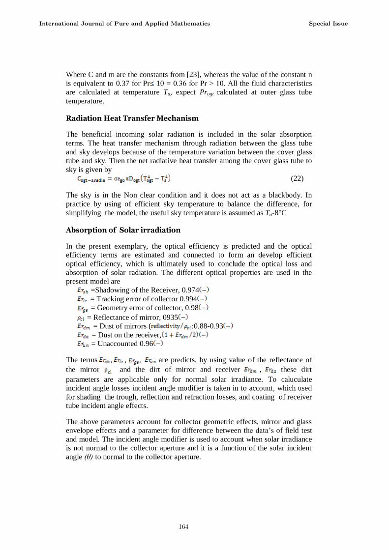
Radiation Heat Transfer Mechanism
The beneficial incoming solar radiation is included in the solar absorption
terms. The heat transfer mechanism through radiation between the glass tube
and sky develops because of the temperature variation between the cover glass
tube and sky. Then the net radiative heat transfer among the cover glass tube to
sky is given by
(22)
The sky is in the Non clear condition and it does not act as a blackbody. In
practice by using of efficient sky temperature to balance the difference, for
simplifying the model, the useful sky temperature is assumed as Ta-8°C
Absorption of Solar irradiation
In the present exemplary, the optical efficiency is predicted and the optical
efficiency terms are estimated and connected to form an develop efficient
optical efficiency, which is ultimately used to conclude the optical loss and
absorption of solar radiation. The different optical properties are used in the
present model are
=Shadowing of the Receiver, 0.974
= Tracking error of collector 0.994
= Geometry error of collector, 0.98
= Reflectance of mirror, 0935
= Dust of mirrors ( :0.88-0.93
= Dust on the receiver,
= Unaccounted 0.96
The terms , , are predicts, by using value of the reflectance of
the mirror and the dirt of mirror and receiver , these dirt
parameters are applicable only for normal solar irradiance. To caluculate
incident angle losses incident angle modifier is taken in to account, which used
for shading the trough, reflection and refraction losses, and coating of receiver
tube incident angle effects.
The above parameters account for collector geometric effects, mirror and glass
envelope effects and a parameter for difference between the data’s of field test
and model. The incident angle modifier is used to account when solar irradiance
is not normal to the collector aperture and it is a function of the solar incident
angle (θ) to normal to the collector aperture.
International Journal of Pure and Applied Mathematics Special Issue
164
(24)
For the calculation of optical losses optical properties of selective coating
absorptance and emittance are appropriated. The glass tube absorptance and
emmitance are constant and independent of type of selective coating. The glass
tube transmittance, metal tube selective coating absorptance and emittance
depends on the coating type. Both the glass tube transmittance and selective
coating absorptance are constants.
Glass envelope transmittance=0.935(-)
Absorptance of selective coating=0.92 (-)
Selective coating emittance=At 100°C the value is 0.06 and 0.15 at 400°C the
value is 0.15(-)
Selective coating emittance, =0.000327(T+273.15)-0.065971
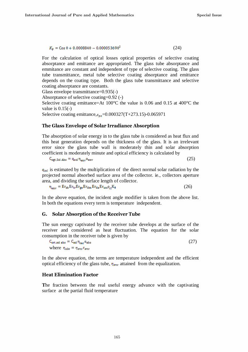
The Glass Envelope of Solar Irradiance Absorption
The absorption of solar energy in to the glass tube is considered as heat flux and
this heat generation depends on the thickness of the glass. It is an irrelevant
error since the glass tube wall is moderately thin and solar absorption
coefficient is moderately minute and optical efficiency is calculated by
(25)
is estimated by the multiplication of the direct normal solar radiation by the
projected normal absorbed surface area of the collector. ie., collectors aperture
area, and dividing the surface length of collector.
(26)
In the above equation, the incident angle modifier is taken from the above list.
In both the equations every term is temperature independent.
G. Solar Absorption of the Receiver Tube
The sun energy captivated by the receiver tube develops at the surface of the
receiver and considered as heat fluctuation. The equation for the solar
consumption in the receiver tube is given by
(27)
where
In the above equation, the terms are temperature independent and the efficient
optical efficiency of the glass tube, attained from the equalization.
Heat Elimination Factor
The fraction between the real useful energy advance with the captivating
surface at the partial fluid temperature
International Journal of Pure and Applied Mathematics Special Issue
165
(28)
is the collector performance factor
(29)
The factor reffers collector heat loss coefficient is the sum of coefficients for
heat transfer mechanism through conduction of the glass cover, convection heat
transfer through convection from the outer receiver tube to the annular and
space to ambient, and the heat transfer mechanism through radiation from outer
receiver tube to the sky.
III. Result and Discussions
Thermal analysis has been carried out for the present Cylindrical trough solar
concentrator system in the Department of Physics, KAHE, Coimbatore, India.
The conduction heat transfer coefficient for the proposed system has been found
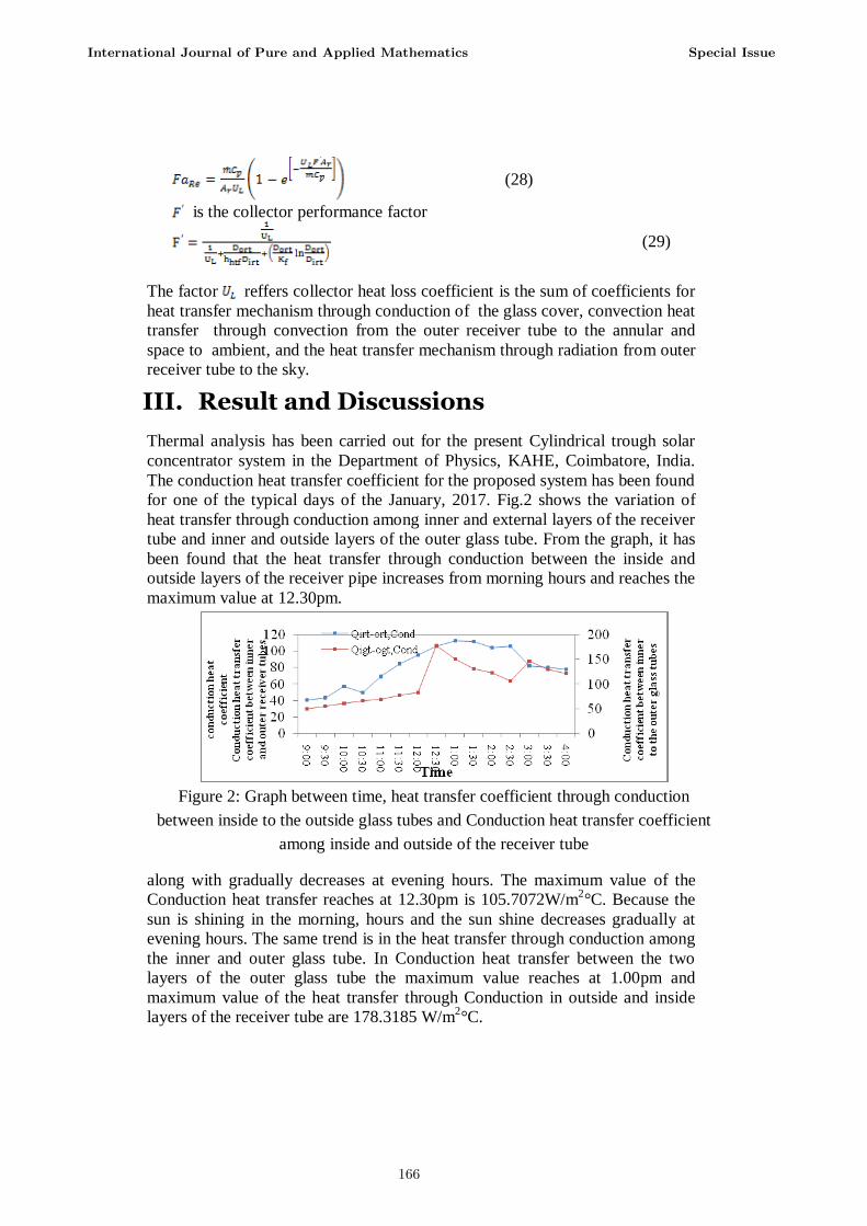
for one of the typical days of the January, 2017. Fig.2 shows the variation of
heat transfer through conduction among inner and external layers of the receiver
tube and inner and outside layers of the outer glass tube. From the graph, it has
been found that the heat transfer through conduction between the inside and
outside layers of the receiver pipe increases from morning hours and reaches the
maximum value at 12.30pm.
Figure 2: Graph between time, heat transfer coefficient through conduction
between inside to the outside glass tubes and Conduction heat transfer coefficient
among inside and outside of the receiver tube
along with gradually decreases at evening hours. The maximum value of the
Conduction heat transfer reaches at 12.30pm is 105.7072W/m2°C. Because the
sun is shining in the morning, hours and the sun shine decreases gradually at
evening hours. The same trend is in the heat transfer through conduction among
the inner and outer glass tube. In Conduction heat transfer between the two
layers of the outer glass tube the maximum value reaches at 1.00pm and
maximum value of the heat transfer through Conduction in outside and inside
layers of the receiver tube are 178.3185 W/m2°C.
International Journal of Pure and Applied Mathematics Special Issue
166
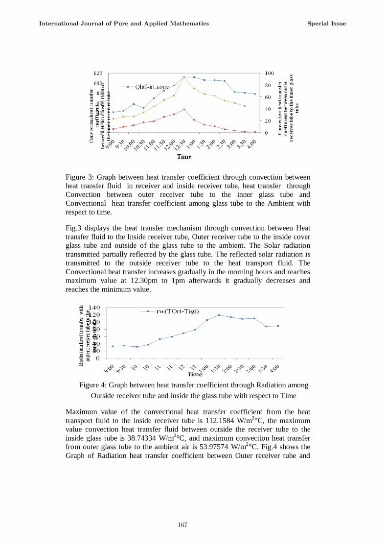
Figure 3: Graph between heat transfer coefficient through convection between
heat transfer fluid in receiver and inside receiver tube, heat transfer through
Convection between outer receiver tube to the inner glass tube and
Convectional heat transfer coefficient among glass tube to the Ambient with
respect to time.
Fig.3 displays the heat transfer mechanism through convection between Heat
transfer fluid to the Inside receiver tube, Outer receiver tube to the inside cover
glass tube and outside of the glass tube to the ambient. The Solar radiation
transmitted partially reflected by the glass tube. The reflected solar radiation is
transmitted to the outside receiver tube to the heat transport fluid. The
Convectional heat transfer increases gradually in the morning hours and reaches
maximum value at 12.30pm to 1pm afterwards it gradually decreases and
reaches the minimum value.
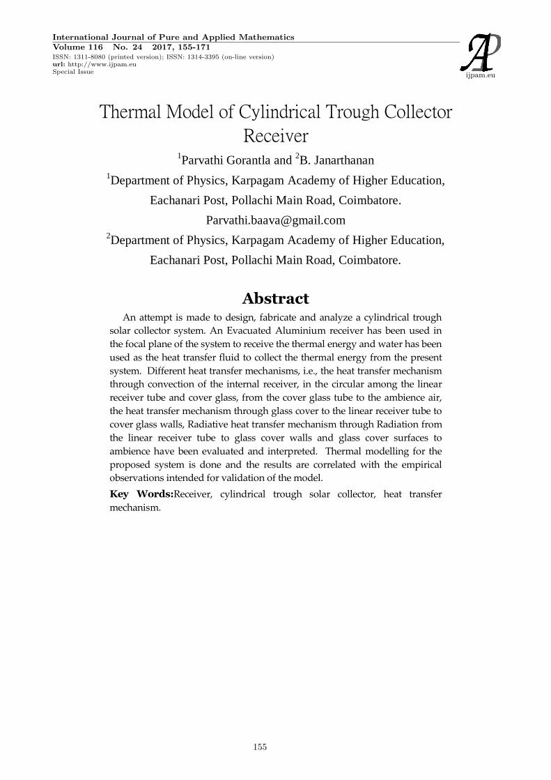
Figure 4: Graph between heat transfer coefficient through Radiation among
Outside receiver tube and inside the glass tube with respect to Time
Maximum value of the convectional heat transfer coefficient from the heat
transport fluid to the inside receiver tube is 112.1584 W/m2°C, the maximum
value convection heat transfer fluid between outside the receiver tube to the
inside glass tube is 38.74334 W/m2°C, and maximum convection heat transfer
from outer glass tube to the ambient air is 53.97574 W/m2°C. Fig.4 shows the
Graph of Radiation heat transfer coefficient between Outer receiver tube and
International Journal of Pure and Applied Mathematics Special Issue
167
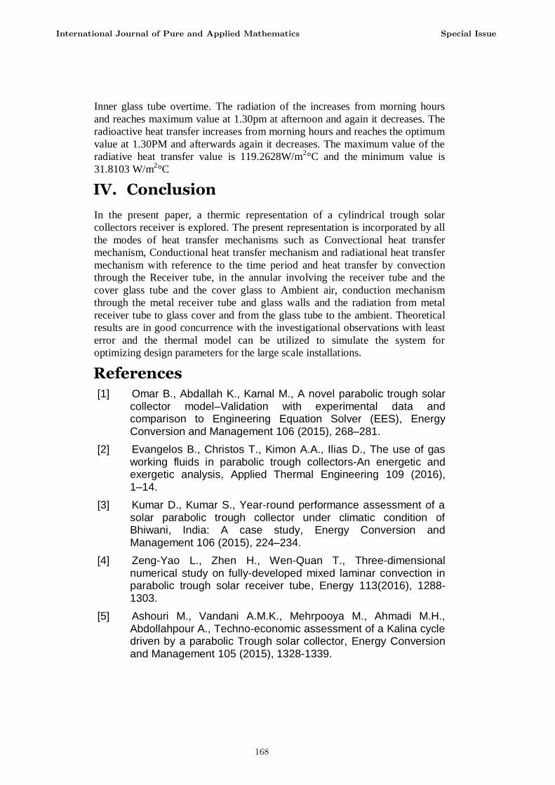
Inner glass tube overtime. The radiation of the increases from morning hours
and reaches maximum value at 1.30pm at afternoon and again it decreases. The
radioactive heat transfer increases from morning hours and reaches the optimum
value at 1.30PM and afterwards again it decreases. The maximum value of the
radiative heat transfer value is 119.2628W/m2°C and the
minimum value is
31.8103 W/m2°C
IV. Conclusion
In the present paper, a thermic representation of a cylindrical trough solar
collectors receiver is explored. The present representation is incorporated by all
the modes of heat transfer mechanisms such as Convectional heat transfer
mechanism, Conductional heat transfer mechanism and radiational heat transfer
mechanism with reference to the time period and heat transfer by convection
through the Receiver tube, in the annular involving the receiver tube and the
cover glass tube and the cover glass to Ambient air, conduction mechanism
through the metal receiver tube and glass walls and the radiation from metal
receiver tube to glass cover and from the glass tube to the ambient. Theoretical
results are in good concurrence with the investigational observations with least
error and the thermal model can be utilized to simulate the system for
optimizing design parameters for the large scale installations.
References
[1] Omar B., Abdallah K., Kamal M., A novel parabolic trough solar collector model–Validation with experimental data and comparison to Engineering Equation Solver (EES), Energy Conversion and Management 106 (2015), 268–281.
[2] Evangelos B., Christos T., Kimon A.A., Ilias D., The use of gas working fluids in parabolic trough collectors-An energetic and exergetic analysis, Applied Thermal Engineering 109 (2016), 1–14.
[3] Kumar D., Kumar S., Year-round performance assessment of a solar parabolic trough collector under climatic condition of Bhiwani, India: A case study, Energy Conversion and Management 106 (2015), 224–234.
[4] Zeng-Yao L., Zhen H., Wen-Quan T., Three-dimensional numerical study on fully-developed mixed laminar convection in parabolic trough solar receiver tube, Energy 113(2016), 1288-1303.
[5] Ashouri M., Vandani A.M.K., Mehrpooya M., Ahmadi M.H., Abdollahpour A., Techno-economic assessment of a Kalina cycle driven by a parabolic Trough solar collector, Energy Conversion and Management 105 (2015), 1328-1339.
International Journal of Pure and Applied Mathematics Special Issue
168
[6] Mokheimer E.M., Dabwan Y.N., Habib M.A., Said S.A., Al-Sulaiman F.A., Techno-economic performance analysis of parabolic trough collector in Dhahran, Saudi Arabia, Energy Conversion and Management 86 (2014), 622-633.
[7] Yılmaz I.H., Soylemez M.S., Thermo-mathematical modeling of parabolic trough collector, Energy Conversion and Management. 88 (2014), 768–784.
[8] Huang W., Hu P., Chen Z., Performance simulation of a parabolic trough solar collector, Solar Energy 86 (2012), 746–755.
[9] Marif Y., Benmoussa H., Bouguettaia H., Belhadj M.M., Zerrouki M., Numerical simulation of solar parabolic trough collector performance in the Algeria Saharan region, Energy Conversion and Management 85 (2014), 521–529.
[10] Huang Z., Li Z.Y., Tao W.Q., Numerical study on combined natural and forced convection in the fully-developed turbulent region for a horizontal circular tube heated by non-uniform heat flux, Applied Energy, 2194-2208.
[11] Xu R., Wiesner T.F., Closed-form modeling of direct steam generation in a parabolic trough solar receiver, Energy 79 (2015), 163-176.
[12] Mwesigye A., Bello-Ochende T., Meyer J.P., Numerical investigation of entropy generation in a parabolic trough receiver at different concentration ratios, Energy 53 (2013), 114-127.
[13] Lu J., Ding J., Yang J., Yang X., Nonuniform heat transfer model and performance of parabolic trough solar receiver, Energy 59 (2013), 666-675
[14] Barbero R., Rovira A., Montes M.J., Val J.M.M., A new approach for the prediction of thermal efficiency in solar receivers, Energy Conversion and Management 123 (2016), 498–511.
[15] Li Q., Zheng C., Mesgari S., Hewkuruppu Y.L., Hjerrild N., Crisostomo F., Rosengarten G., Scott J.A., Taylor R.A., Experimental and numerical investigation of volumetric versus surface solar absorbers for a concentrated solar thermal collector, Solar Energy 136 (2016), 349-364.
[16] Gnielnski V., New equations for heat and mass transfer in turbulent pipe and channel flow, International Chemical Engineering 562 (2) (1976), 359-63.
[17] Davis J.R., Alloy digest, sourcebook, stainless steels. Materials Park, OH: ASM, 2000
International Journal of Pure and Applied Mathematics Special Issue
169
[18] Bejan A., Convection Heat Transfer, Second Edition, New York, NY: John Wiley & Sons, 1995.
[19] Touloukian Y.S, DeWitt D.P., Radiative properties, nonmetalic solids, thermophysical properties of matter, New York: Plenum Publishing, 1972.
[20] Incropera F., DeWitt D., Fundamentals of Heat and Mass Transfer, Third Edition, New York, NY: John Wiley and Sons, 1990.
[21] Incropera F., DeWitt D., Bergman T.L., Lavine A.S., Fundamentals of heat and mass transfer, 6th ed. New York: John Wiley and Sons, 2007.
International Journal of Pure and Applied Mathematics Special Issue
170

171

172